EP3444445A1 - Dispositif de fusible mécanique et procédé de fonctionnement d'un dispositif de fusible mécanique - Google Patents
Dispositif de fusible mécanique et procédé de fonctionnement d'un dispositif de fusible mécanique Download PDFInfo
- Publication number
- EP3444445A1 EP3444445A1 EP18187778.8A EP18187778A EP3444445A1 EP 3444445 A1 EP3444445 A1 EP 3444445A1 EP 18187778 A EP18187778 A EP 18187778A EP 3444445 A1 EP3444445 A1 EP 3444445A1
- Authority
- EP
- European Patent Office
- Prior art keywords
- torque
- connecting parts
- fuse device
- mechanical fuse
- ring gear
- Prior art date
- Legal status (The legal status is an assumption and is not a legal conclusion. Google has not performed a legal analysis and makes no representation as to the accuracy of the status listed.)
- Withdrawn
Links
Images


Classifications
-
- F—MECHANICAL ENGINEERING; LIGHTING; HEATING; WEAPONS; BLASTING
- F01—MACHINES OR ENGINES IN GENERAL; ENGINE PLANTS IN GENERAL; STEAM ENGINES
- F01D—NON-POSITIVE DISPLACEMENT MACHINES OR ENGINES, e.g. STEAM TURBINES
- F01D21/00—Shutting-down of machines or engines, e.g. in emergency; Regulating, controlling, or safety means not otherwise provided for
- F01D21/04—Shutting-down of machines or engines, e.g. in emergency; Regulating, controlling, or safety means not otherwise provided for responsive to undesired position of rotor relative to stator or to breaking-off of a part of the rotor, e.g. indicating such position
- F01D21/045—Shutting-down of machines or engines, e.g. in emergency; Regulating, controlling, or safety means not otherwise provided for responsive to undesired position of rotor relative to stator or to breaking-off of a part of the rotor, e.g. indicating such position special arrangements in stators or in rotors dealing with breaking-off of part of rotor
-
- F—MECHANICAL ENGINEERING; LIGHTING; HEATING; WEAPONS; BLASTING
- F16—ENGINEERING ELEMENTS AND UNITS; GENERAL MEASURES FOR PRODUCING AND MAINTAINING EFFECTIVE FUNCTIONING OF MACHINES OR INSTALLATIONS; THERMAL INSULATION IN GENERAL
- F16D—COUPLINGS FOR TRANSMITTING ROTATION; CLUTCHES; BRAKES
- F16D9/00—Couplings with safety member for disconnecting, e.g. breaking or melting member
- F16D9/06—Couplings with safety member for disconnecting, e.g. breaking or melting member by breaking due to shear stress
-
- F—MECHANICAL ENGINEERING; LIGHTING; HEATING; WEAPONS; BLASTING
- F02—COMBUSTION ENGINES; HOT-GAS OR COMBUSTION-PRODUCT ENGINE PLANTS
- F02C—GAS-TURBINE PLANTS; AIR INTAKES FOR JET-PROPULSION PLANTS; CONTROLLING FUEL SUPPLY IN AIR-BREATHING JET-PROPULSION PLANTS
- F02C3/00—Gas-turbine plants characterised by the use of combustion products as the working fluid
- F02C3/04—Gas-turbine plants characterised by the use of combustion products as the working fluid having a turbine driving a compressor
- F02C3/107—Gas-turbine plants characterised by the use of combustion products as the working fluid having a turbine driving a compressor with two or more rotors connected by power transmission
-
- F—MECHANICAL ENGINEERING; LIGHTING; HEATING; WEAPONS; BLASTING
- F02—COMBUSTION ENGINES; HOT-GAS OR COMBUSTION-PRODUCT ENGINE PLANTS
- F02C—GAS-TURBINE PLANTS; AIR INTAKES FOR JET-PROPULSION PLANTS; CONTROLLING FUEL SUPPLY IN AIR-BREATHING JET-PROPULSION PLANTS
- F02C7/00—Features, components parts, details or accessories, not provided for in, or of interest apart form groups F02C1/00 - F02C6/00; Air intakes for jet-propulsion plants
- F02C7/36—Power transmission arrangements between the different shafts of the gas turbine plant, or between the gas-turbine plant and the power user
-
- F—MECHANICAL ENGINEERING; LIGHTING; HEATING; WEAPONS; BLASTING
- F02—COMBUSTION ENGINES; HOT-GAS OR COMBUSTION-PRODUCT ENGINE PLANTS
- F02K—JET-PROPULSION PLANTS
- F02K3/00—Plants including a gas turbine driving a compressor or a ducted fan
- F02K3/02—Plants including a gas turbine driving a compressor or a ducted fan in which part of the working fluid by-passes the turbine and combustion chamber
- F02K3/04—Plants including a gas turbine driving a compressor or a ducted fan in which part of the working fluid by-passes the turbine and combustion chamber the plant including ducted fans, i.e. fans with high volume, low pressure outputs, for augmenting the jet thrust, e.g. of double-flow type
- F02K3/06—Plants including a gas turbine driving a compressor or a ducted fan in which part of the working fluid by-passes the turbine and combustion chamber the plant including ducted fans, i.e. fans with high volume, low pressure outputs, for augmenting the jet thrust, e.g. of double-flow type with front fan
-
- F—MECHANICAL ENGINEERING; LIGHTING; HEATING; WEAPONS; BLASTING
- F05—INDEXING SCHEMES RELATING TO ENGINES OR PUMPS IN VARIOUS SUBCLASSES OF CLASSES F01-F04
- F05D—INDEXING SCHEME FOR ASPECTS RELATING TO NON-POSITIVE-DISPLACEMENT MACHINES OR ENGINES, GAS-TURBINES OR JET-PROPULSION PLANTS
- F05D2220/00—Application
- F05D2220/30—Application in turbines
- F05D2220/32—Application in turbines in gas turbines
-
- F—MECHANICAL ENGINEERING; LIGHTING; HEATING; WEAPONS; BLASTING
- F05—INDEXING SCHEMES RELATING TO ENGINES OR PUMPS IN VARIOUS SUBCLASSES OF CLASSES F01-F04
- F05D—INDEXING SCHEME FOR ASPECTS RELATING TO NON-POSITIVE-DISPLACEMENT MACHINES OR ENGINES, GAS-TURBINES OR JET-PROPULSION PLANTS
- F05D2260/00—Function
- F05D2260/30—Retaining components in desired mutual position
- F05D2260/31—Retaining bolts or nuts
- F05D2260/311—Retaining bolts or nuts of the frangible or shear type
-
- F—MECHANICAL ENGINEERING; LIGHTING; HEATING; WEAPONS; BLASTING
- F05—INDEXING SCHEMES RELATING TO ENGINES OR PUMPS IN VARIOUS SUBCLASSES OF CLASSES F01-F04
- F05D—INDEXING SCHEME FOR ASPECTS RELATING TO NON-POSITIVE-DISPLACEMENT MACHINES OR ENGINES, GAS-TURBINES OR JET-PROPULSION PLANTS
- F05D2260/00—Function
- F05D2260/40—Transmission of power
- F05D2260/403—Transmission of power through the shape of the drive components
- F05D2260/4031—Transmission of power through the shape of the drive components as in toothed gearing
- F05D2260/40311—Transmission of power through the shape of the drive components as in toothed gearing of the epicyclical, planetary or differential type
Definitions
- the invention relates to a mechanical fuse device with the features of claim 1 and a method for operating a mechanical fuse device with the features of claim 13.
- Geared turbofan aircraft engines sometimes require some means to mitigate damages that might occur after a failure.
- a failure might involve the rotation prevention of at least one part of the drive train.
- Such a failure might be e.g. a shaft breaking, a rotor-casing contact or a bearing seizure. This becomes even more important for high bypass aircraft engines, in which the drag of a locked fan would be considerable. In other cases the deliberate disengagement of engine parts might be required.
- the mechanical fuse device comprises two connection parts in a geared aircraft turbofan engine.
- the two connecting parts are coupled to ring gears of a gearbox in the geared turbofan engine.
- the mechanical fuse device further comprises a means to automatically trigger a position change in at least one of the two connecting parts relative to the respective other connecting part from a first position into a second position.
- This position change can be e.g. a disengagement of the connecting parts.
- the position change takes place in dependence of a torque effective on the connecting parts.
- the torque is effectively transmitted via a ring gear device, in particular a non-nominal torque or a reversal in the direction of the torque.
- the means to automatically trigger the position change in the mechanical fuse device comprise at least one helical gear for changing the position of at least one of the two connecting parts depending on the torque effective on the connecting parts. All the means can have different torque transmission characteristics depending on the torque input (i.e. the absolute value as well as the direction of the torque).
- the means to automatically trigger the position change comprise two parallel helical gear connections, the helical angles forming an apex.
- the axial loads which are present in a gearbox with two helical gears are put to use in triggering the deliberate position change in the connecting parts of the mechanical fuse device.
- the helical gear connection comprises an apex trailing design or an apex leading design.
- the apex is the geometric intersection of the helical angles of two parallel helical gears, i.e. it defines the orientation of the helical gears.
- the axial load works from the inside to the outside.
- the axial load works from the outside to the inside.
- the changing of the position of the connecting parts depends on an axial load transmitted by the helical gear connection.
- the movement of a helical gear creates an axial movement or load. This can be used to deliberately apply some load on the bolt connection.
- the bolt connection is designed to fail under predetermined conditions, such as a torque exceeding a certain threshold value or a torque changing directions.
- the axial loading can also lead to a decreased pressure within the bolted flange. This can result in circumferential slipping. This slipping can be used to fail the bolts as well. In particular a shear neck on the bold can be "cut" through the "sharp" engine part.
- two connecting parts are each connected with one ring gear device, the two connecting parts being connected to each other with at least one bolt connection the at least one bolt connection designed to fail under a predetermined torque, i.e. a predetermined value, or a predetermined torque direction.
- a predetermined torque i.e. a predetermined value, or a predetermined torque direction.
- two separate connecting parts are held together with the bolt connection.
- two connecting parts are each connected with one ring gear device, the two connecting parts being connected to the ring gear devices with bolt connections designed to fail under a predetermined torque or a predetermined torque direction.
- the connecting parts are both located on one device.
- the connecting parts connect the two ring gear devices of the gearbox.
- the torque transmission characteristics of the helical gear connection is asymmetric relative to the torque applied to the helical gear connection. This means that the behavior of the mechanical fuse device depends on the direction of the torque applied.
- first and / or second connecting parts are rigidly connected to the ring gear mount of the gearbox or the first connecting part is in one piece with the ring gear mount of the gearbox or to a support structure of the engine, such as a casing.
- the first and / or second connecting part can, in one embodiment, be coupled to the input shaft and / or the output shaft of the gearbox.
- the mechanical fuse device can be e.g. used to release the ring gear mount decoupling a driven part, in particular a propulsive fan, in the case of a disruptive event (e.g. gearbox seizure).
- a disruptive event e.g. gearbox seizure
- the planetary gearbox is coupled to a propulsive fan of a geared aircraft turbofan engine, the propulsive fan being configured to drive an electrical generator in windmilling operation conditions via the gearbox and the ring gear mount.
- the propulsive fan is not actively driven by the primary power source such as the turbine, the fan should at least freely rotate (windmilling) because otherwise the engine has a large aerodynamic drag.
- the propulsive fan can being configured to be driven by external power source (e.g. an electrical motor, e.g. driven by the ring gear mount which lead to the powering of the propulsive fan) when decoupled through the mechanicals fuse from its primary power source.
- a means automatically triggers automatically a position change (e.g. disengagement) in or of the mechanical fuse device from the first position into a second position of at least one of the two connecting parts relative to the respective other connection part in dependence of a torque effective on at least one of the two connecting parts,
- the torque is effectively transmitted via at least one ring gear device of the gearbox, in particular a non-nominal torque or a reversal in the direction of the torque.
- One embodiment of the method comprises the disengagement of the mechanical fuse device resulting in the decoupling of the gearbox from other parts of the geared aircraft turbo engine.
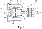
- a geared turbo fan engine is generally indicated at 10, having a principal and rotational axis 11.
- the engine 10 comprises, in axial flow series, an air intake 32, a propulsive fan 13 (could be more than one stage), a gearbox 14, an intermediate pressure compressor 15, a high-pressure compressor 16, a combustion equipment 17, a high-pressure turbine 18, an intermediate-pressure turbine 19 and an exhaust nozzle 20.
- a fan casing 21 generally surrounds the engine 10 and defines the intake 32.
- the geared turbofan engine 10 works in the conventional manner so that air entering the intake 32 is accelerated by the propulsive fan 13 to produce two air flows: a first air flow into the intermediate pressure compressor 15 and a second air flow which passes through a bypass duct 22 to provide the main propulsive thrust.
- the intermediate pressure compressor 15 compresses the airflow directed into it before delivering that air to the high pressure compressor 16 where further compression takes place.
- the compressed air exhausted from the high-pressure compressor 16 is directed into the combustion equipment 17 where it is mixed with fuel and the mixture is combusted.
- the resultant hot combustion products then expand through, and thereby drive the high pressure turbine 18 and intermediate pressure turbine 19 before being exhausted through the nozzle 20 to provide additional propulsive thrust.
- An intermediate pressure shaft also drives the propulsive fan 13 via the gearbox 14.
- the gearbox 14 is a reduction gearbox in that it gears down the rate of rotation of the propulsive fan 13 by comparison with the intermediate pressure compressor 15 and intermediate pressure turbine 19.
- the gearbox 14 in the embodiment shown is an epicyclic planetary gearbox (see also Fig. 5 ) having static ring gear devices 111, 112, rotating and orbiting planet gears 103 supported by a planet carrier 104 and a rotating sun gear 102.
- the ring gear devices 111, 112 comprise each a helical gearing.
- the helical gearing is so oriented that the helical angles form an apex.
- the planetary gears 103 have two matching gears for the helical gear devices 111, 112.
- Fig. 1 has a specific shaft arrangement which is understood not to be limiting.
- the embodiments described in the following can also work with a 2- or 3-shaft arrangement.
- geared turbofan engines 10 are known in the art. With increasing power ratings and / or increasing diameters of the propulsive fans 13, the loads on the geared turbofan engine 10 are increasing. Therefore, it seems advisable to introduce flexible measures to operate rotational parts and e.g. counteract potential failure modes or extreme events such as e.g. a fan blade off, a core blade off, a bird strike, a mainline bearing seizure or a gearbox 14 seizure.
- a first embodiment of a mechanical fuse device 1 is shown.
- the mechanical fuse device 1 is here coupled at one end with the ring gear mount 101 of a geared turbofan engine 10 as shown in Fig. 1 .
- the mechanical fuse device 1 is coupled to ring gears devices 111, 112.
- the connection to the ring gear mount 101 is in particular shown in connection with Fig. 5 .
- the mechanical fuse device 1 comprises two connecting parts 31, 32. Connecting means in this context that the connecting parts 31, 32 under nominal operation conditions connect the ring gear mount devices 111, 112 and the ring gear mount 101.
- Fig. 2 the connected position of the mechanical fuse device 1 is shown, i.e. the situation under nominal operating conditions.
- the connecting parts 31, 32 are positioned fixedly - through a bolt connection 34 - relative to the ring gear mount 101 of the gearbox 14 of the geared turbofan engine 10.
- the ring gear mount 101 is connected to a fixed part 107 of the engine 10, here a front panel.
- Fig. 2 shows this geometric relationship only in a very schematic way.
- the mechanical fuse device 1 comprises means 40 for automatically triggering a position change (e.g. a disengagement) of the mechanical fuse device 1 by bringing at least one of the connecting parts 31, 32 relative to the other connecting parts 32, 31 into a disengagement position in dependence of the effective torque T on the connecting parts 31, 32.
- a position change e.g. a disengagement
- the means 40 for automatically triggering the position change comprise two helical gear connections 42 each coupled to one of the the two ring gears devices 111, 112.
- the bolt connection 34 Under nominal operation conditions, i.e. the torque is within design limits and the direction of the torque is nominal, the bolt connection 34 withstands the axial load generated by the helical gear connections 42.
- Helical gear connections 42 have ridges or teeth that mesh with grooves in a mating piece and transfer to it.
- a helical spine comprises equally spaced grooves forming a about the shaft. The sides may be parallel or involute. This can either minimize stress concentrations for a stationary joint under high load, or allow for rotary and linear motion between the parts.
- Another feature of the helical gear is that it reacts differently to torque T in different directions.
- the helical gear connection generates an axial load which can open or close the mechanical fuse device 1; a helical gear can translate an angular movement into an axial movement.
- the helical angle can be between 15 and 45°.
- the bolt connection 34 will axially fail under a non-nominal torque direction, i.e. if a negative torque T is applied. This means that the helical gear connections 42 will produce an axial load above a predetermined design level under the negative torque T.
- the bolt connection 34 will axially fail under an excessive torque T, i.e. the torque T it exceeding a predetermined design value.
- a second embodiment is shown involving a mechanical fuse device 1 coupled to the ring gear mount 101.
- the connecting parts 31, 32 are part of an essentially Y-shaped part, connecting parts 31, 32 forming the two prongs of the Y coupled to ring gear devices 111, 112 through two bolt connections 34.
- the base 35 of the Y is connected to the ring gear mount 101.
- the means 40 for automatically triggering the position change comprise two helical gear connections 42 coupled to the ring gear devices 111, 112. Under nominal operation conditions, i.e. the torque is within design limits and the direction of the torque is nominal, the bolt connections 34 withstand the axial load generated by the gear connections 42.
- the apex design for the helical gear connection 42 gives rise to two different embodiments.
- the bolt connection 34 will axially fail under a non-nominal torque, i.e. a torque T exceeding a predetermined design value.
- the bolt connection 34 will axially fail under a negative torque, i.e. a torque deviating from the predetermined design direction.
- the functionality of the mechanical fuse device 1 including a preloading of the bolt connection 34 can be seen schematically in Fig. 4 illustrating the transmittable torque T, T' through a mechanical fuse device 1.
- the power which is generated or consumed by a geared turbofan engine 10 with a propulsive fan 13 is plotted on the x-axis.
- Positive power values represent nominal operation, i.e. the turbine is driving the system.
- Negative power values represent a non-nominal case in which the system is driven by the propulsive fan 13 (e.g. windmilling in case of a gearbox failure, no driving through turbine).
- the transmittable torque T, T' is plotted on the y-axis.
- the geared turbofan engine 10 is turbine driven and the torque T is positive, i.e. the operation is nominal.
- the slope of the dashed line indicating the transmittable torque T is smaller than the slope of the line representing the torque the ring gear mount. At the point where the transmittable torque T becomes smaller than the ring gear torque, the clutch in the mechanical fuse begins to slip.
- the sign of the transmittable torque T' is reversed and the mechanical fuse device 1 moves from the first to the second position disengaging the gearbox in the process.
- the propulsive fan 13 now can turn freely in windmilling mode. Thereby, some torque can be transmitted, which can e.g. drive a generator of generating electrical power.
- the torque preloading has the effect that at zero power generation, i.e. with the engine at rest, some preloaded torque is present. This can be seen by the positive offset O and negative offset O' along the y-axis. This implies that for the change in the position of the connecting parts 31, 32 the preloaded torque needs to be overcome before the ring gear mount 101 becomes disengaged.
- the mechanical fuse device 1 disengages.
- FIG. 5 some design context for the placement of the mechanical fuse device 1 is given.
- the view of Fig. 5 is a cross-section through the front of a geared turbofan engine 10 (see e.g. Fig. 1 ).
- the gearbox 14 is having a planetary arrangement.
- the turbine (not shown in Fig. 5 ) is driving the sun gear 102 of the gearbox 14 through a driving shaft 106.
- the torque is transmitted via the planetary gears 103 to the carrier 104 providing the output torque of the gearbox 14 (indicated by the arrow) via an output shaft 108.
- the ring gear mount 101 is static relative to the other part under nominal conditions.
- the embodiments of the mechanical fuse device can be located between the static ring gear mount 101 and a fixed part 107 of the air craft engine. Alternatively it can be located between the sun gear 102 and the sun shaft, i.e the driving shaft 106.
- the two connecting parts 31, 32 are under nominal conditions at rest - static - relative to each other.
- the connecting parts 31, 32 can disengage under non-nominal conditions as described above.
- the embodiments described herein can e.g. be used in connection with a management of the rotatory behavior of the propulsive fan 13.
- the propulsive fan 13 is not required to provide thrust (e.g. windmilling after a gearbox 14 seizure or another failure, descent phase of an airplane).
- the decoupling of the propulsive fan 13 using a mechanical fuse device 1 provides an operation regime in which the propulsive fan 13 can freely rotate. If e.g. the operation requires a reengagement, the mechanical clutch device 1 couples the propulsive fan 1 back to a torque T source, e.g. a turbine stage.
Landscapes
- Engineering & Computer Science (AREA)
- General Engineering & Computer Science (AREA)
- Mechanical Engineering (AREA)
- Chemical & Material Sciences (AREA)
- Combustion & Propulsion (AREA)
- Retarders (AREA)
- General Details Of Gearings (AREA)
Applications Claiming Priority (1)
| Application Number | Priority Date | Filing Date | Title |
|---|---|---|---|
| DE102017214459 | 2017-08-18 |
Publications (1)
| Publication Number | Publication Date |
|---|---|
| EP3444445A1 true EP3444445A1 (fr) | 2019-02-20 |
Family
ID=63254525
Family Applications (1)
| Application Number | Title | Priority Date | Filing Date |
|---|---|---|---|
| EP18187778.8A Withdrawn EP3444445A1 (fr) | 2017-08-18 | 2018-08-07 | Dispositif de fusible mécanique et procédé de fonctionnement d'un dispositif de fusible mécanique |
Country Status (2)
| Country | Link |
|---|---|
| US (1) | US20190055991A1 (fr) |
| EP (1) | EP3444445A1 (fr) |
Cited By (1)
| Publication number | Priority date | Publication date | Assignee | Title |
|---|---|---|---|---|
| US20210270147A1 (en) * | 2020-02-27 | 2021-09-02 | Rolls-Royce Deutschland Ltd & Co Kg | Torque limiting device in a connection between a gearbox and a stationary structure in a gas turbine engine and a gas turbine engine |
Families Citing this family (4)
| Publication number | Priority date | Publication date | Assignee | Title |
|---|---|---|---|---|
| CN111980958B (zh) * | 2019-05-21 | 2021-09-10 | 中国航发商用航空发动机有限责任公司 | 一种熔断系统和航空发动机 |
| FR3108140B1 (fr) * | 2020-03-10 | 2022-05-13 | Safran Aircraft Engines | Module de turbomachine equipe d’un rotor de machine electrique |
| US11002146B1 (en) | 2020-10-26 | 2021-05-11 | Antheon Research, Inc. | Power generation system |
| US11530617B2 (en) | 2020-10-26 | 2022-12-20 | Antheon Research, Inc. | Gas turbine propulsion system |
Citations (3)
| Publication number | Priority date | Publication date | Assignee | Title |
|---|---|---|---|---|
| GB1282400A (en) * | 1971-06-30 | 1972-07-19 | Rolls Royce 1971 Ltd | Shaft connection |
| US20040156669A1 (en) * | 2003-01-17 | 2004-08-12 | Snecma Moteurs | Retaining device for a connection device, decoupling system equipped with such a device |
| US20170108084A1 (en) * | 2015-10-15 | 2017-04-20 | Rolls-Royce Plc | Geared gas turbine engine |
-
2018
- 2018-07-26 US US16/046,364 patent/US20190055991A1/en not_active Abandoned
- 2018-08-07 EP EP18187778.8A patent/EP3444445A1/fr not_active Withdrawn
Patent Citations (3)
| Publication number | Priority date | Publication date | Assignee | Title |
|---|---|---|---|---|
| GB1282400A (en) * | 1971-06-30 | 1972-07-19 | Rolls Royce 1971 Ltd | Shaft connection |
| US20040156669A1 (en) * | 2003-01-17 | 2004-08-12 | Snecma Moteurs | Retaining device for a connection device, decoupling system equipped with such a device |
| US20170108084A1 (en) * | 2015-10-15 | 2017-04-20 | Rolls-Royce Plc | Geared gas turbine engine |
Cited By (2)
| Publication number | Priority date | Publication date | Assignee | Title |
|---|---|---|---|---|
| US20210270147A1 (en) * | 2020-02-27 | 2021-09-02 | Rolls-Royce Deutschland Ltd & Co Kg | Torque limiting device in a connection between a gearbox and a stationary structure in a gas turbine engine and a gas turbine engine |
| US11879383B2 (en) * | 2020-02-27 | 2024-01-23 | Rolls-Royce Deutschland Ltd & Co Kg | Torque limiting device in a connection between a gearbox and a stationary structure in a gas turbine engine and a gas turbine engine |
Also Published As
| Publication number | Publication date |
|---|---|
| US20190055991A1 (en) | 2019-02-21 |
Similar Documents
| Publication | Publication Date | Title |
|---|---|---|
| EP3444445A1 (fr) | Dispositif de fusible mécanique et procédé de fonctionnement d'un dispositif de fusible mécanique | |
| US10954813B2 (en) | Planetary gearbox system and method for operating a planetary gearbox system | |
| US10753409B2 (en) | Mechanical clutch device and method for operating a mechanical clutch device | |
| US8169100B2 (en) | Torque transmission for an aircraft engine | |
| US20180252166A1 (en) | Geared turbofan | |
| EP3361057A2 (fr) | Rotor de turbine ayant de faibles exigences de survitesse | |
| EP3121469A1 (fr) | Ensemble arbre d'entraînement | |
| US20180223740A1 (en) | Multi-spool gas turbine engine | |
| EP2935840B1 (fr) | Support avec liaison amont axiale permettant de relier une boîte de vitesses à un carter de turbomoteur | |
| US10428741B2 (en) | Gas turbine engine with a geared turbofan arrangement | |
| US10669949B2 (en) | Gas turbine engine with a geared turbofan arrangement | |
| EP3611365A1 (fr) | Dispositif d'accouplement d'un arbre de sortie à un engrenage épicycloïdal, procédé d'accouplement d'un arbre de sortie à un engrenage épicycloïdal et moteur à turbine a gaz | |
| EP3327276A1 (fr) | Turbine à gaz | |
| EP3555446B1 (fr) | Démarreur pneumatique pourvu d'un découpleur | |
| US10626925B2 (en) | Gas turbine engine with a geared turbofan arrangement | |
| EP3396115A1 (fr) | Turbine à gaz | |
| CN110529510B (zh) | 气体涡轮引擎联接装置 | |
| US10502144B2 (en) | Gas turbine engine with a geared turbofan arrangement | |
| EP3396144B1 (fr) | Moteur à turbine à gaz doté d'un agencement de turboréacteur à réducteur | |
| US11906017B1 (en) | Drive assembly and method of assembly | |
| EP3705704B1 (fr) | Appareil formant arbre pour un moteur à turbine à gaz |
Legal Events
| Date | Code | Title | Description |
|---|---|---|---|
| PUAI | Public reference made under article 153(3) epc to a published international application that has entered the european phase |
Free format text: ORIGINAL CODE: 0009012 |
|
| AK | Designated contracting states |
Kind code of ref document: A1 Designated state(s): AL AT BE BG CH CY CZ DE DK EE ES FI FR GB GR HR HU IE IS IT LI LT LU LV MC MK MT NL NO PL PT RO RS SE SI SK SM TR |
|
| AX | Request for extension of the european patent |
Extension state: BA ME |
|
| 17P | Request for examination filed |
Effective date: 20190820 |
|
| RBV | Designated contracting states (corrected) |
Designated state(s): AL AT BE BG CH CY CZ DE DK EE ES FI FR GB GR HR HU IE IS IT LI LT LU LV MC MK MT NL NO PL PT RO RS SE SI SK SM TR |
|
| STAA | Information on the status of an ep patent application or granted ep patent |
Free format text: STATUS: THE APPLICATION HAS BEEN WITHDRAWN |
|
| 18W | Application withdrawn |
Effective date: 20200716 |