EP3444389A1 - Interlacing device - Google Patents
Interlacing device Download PDFInfo
- Publication number
- EP3444389A1 EP3444389A1 EP18180367.7A EP18180367A EP3444389A1 EP 3444389 A1 EP3444389 A1 EP 3444389A1 EP 18180367 A EP18180367 A EP 18180367A EP 3444389 A1 EP3444389 A1 EP 3444389A1
- Authority
- EP
- European Patent Office
- Prior art keywords
- yarn
- interlacing
- space
- yarn running
- cover member
- Prior art date
- Legal status (The legal status is an assumption and is not a legal conclusion. Google has not performed a legal analysis and makes no representation as to the accuracy of the status listed.)
- Granted
Links
Images


Classifications
-
- D—TEXTILES; PAPER
- D02—YARNS; MECHANICAL FINISHING OF YARNS OR ROPES; WARPING OR BEAMING
- D02J—FINISHING OR DRESSING OF FILAMENTS, YARNS, THREADS, CORDS, ROPES OR THE LIKE
- D02J1/00—Modifying the structure or properties resulting from a particular structure; Modifying, retaining, or restoring the physical form or cross-sectional shape, e.g. by use of dies or squeeze rollers
- D02J1/08—Interlacing constituent filaments without breakage thereof, e.g. by use of turbulent air streams
Definitions
- the present invention relates to an interlacing device configured to interlace one or more yarns using fluid.
- Patent Literature 1 Japanese Unexamined Patent Publication No. 2016-160550 discloses an interlacing device configured to interlace yarns by ejecting fluid from fluid ejection orifices to yarn running spaces provided in an interlacing portion. Fluid ejected from each fluid ejection orifice to the corresponding yarn running space branches into two fluid flows, which respectively head towards opposite sides in a yarn running direction, and then the two fluid flows are respectively discharged through both ends of the yarn running space. Because the flow of the fluid in the yarn running space has a large effect on the interlacing capability, it is preferable that the yarn running space is closed as tightly as possible except the both ends.
- an interlacing device described in Patent Literature 2 Japanese Unexamined Patent Publication No. 2009-133018 ) includes: a first member in which yarn running spaces are disposed; and a second member configured to take a first position of being separated from the first member and a second position of being in contact with the first member. When the second member is in close contact with the first member, the yarn running spaces are tightly closed.
- an interlacing device described in Patent Literature 3 German Unexamined Patent Publication No. DE 10038855 A1 ) is provided with a movable closure member configured to close a yarn insertion gap.
- an object of the present invention is to improve interlacing capability by a low-cost structure.
- an interlacing device includes an interlacing portion including: a yarn running space which is along a yarn running direction; and a fluid ejection orifice from which fluid is ejected to the yarn running space, the interlacing device being configured to interlace a yarn running through the yarn running space by fluid ejected from the fluid ejection orifice, wherein: the interlacing portion includes a yarn insertion gap through which the yarn is inserted into the yarn running space; and a cover member configured to cover the yarn insertion gap is disposed at a position separated from the yarn running space.
- the cover member configured to cover the yarn insertion gap reduces or minimizes the entry of air into the yarn running space through the yarn insertion gap during an interlacing process, and this makes it possible to improve the interlacing capability.
- the cover member is disposed at a position separated from the yarn running space, and therefore the yarn moving around in the yarn running space during the interlacing process never comes into contact with the cover member. Due to this, there is no particular limitation on the material of the cover member.
- the cover member does not have to undergo processing such as polishing in case of contact with the yarn. This leads to cost reduction of the cover member. Accordingly, in the above aspect of the present invention, it is possible to improve the interlacing capability by a low-cost structure.
- the cover member includes a flat lid portion configured to cover the yarn insertion gap at a position separated from the interlacing portion.
- the yarn is wound around a bobbin downstream of the interlacing device, to form a package.
- the tension of the yarn temporarily becomes zero.
- the reduction of the tension to zero slackens the yarn, and the slack yarn may come out through the yarn insertion gap.
- the lid portion is in contact with the interlacing portion in this situation, the coming-out yarn may be caught between the lid portion and the interlacing portion.
- the lid portion is separated from the interlacing portion, and this prevents the yarn from being caught.
- the cover member further includes yarn restricting portions respectively disposed outward of both end faces of the interlacing portion in the yarn running direction, each yarn restricting portion being provided so as to partially overlap the interlacing portion when viewed from the yarn running direction.
- the lid portion is separated from the interlacing portion prevents the yarn from being caught.
- the yarn may greatly come out through the gap between the lid portion and the interlacing portion.
- the above-mentioned yarn restricting portions are provided to the cover member. With this, the yarn trying to come out of the interlacing portion contacts one or each of the yarn restricting portions, and this reliably prevents the yarn from coming out.
- the yarn running space in a cross section orthogonal to the yarn running direction, has a shape symmetrical with respect to a central axis of the fluid ejection orifice, and the yarn insertion gap is along a direction crossing the central axis of the fluid ejection orifice.
- the interlacing device structured as above, fluid flows symmetrically with respect to the central axis of the fluid ejection orifice in the yarn running space, and the flow of the fluid interlaces the yarn.
- the yarn insertion gap is along a direction crossing the central axis of the fluid ejection orifice, however, air entering into the yarn running space through the yarn insertion gap may break the symmetry of the flow, and this tends to increase the degree of deterioration in the interlacing capability.
- the configuration of the present invention that is, to provide the cover member configured to cover the yarn insertion gap, is particularly effective.
- the cover member is configured to be movable between: a first position at which the cover member covers the yarn insertion gap; and a second position at which an open space is created between the cover member and the interlacing portion and the yarn is insertable into the yarn insertion gap through the open space.
- the yarn is easily insertable into the yarn insertion gap by moving the cover member from the first position to the second position. This enables rapid yarn threading to the interlacing device.
- the yarn running space includes a plurality of yarn running spaces and the fluid ejection orifice includes a plurality of fluid ejection orifices
- the interlacing portion is structured by a plurality of interlacing pieces lined up in an arrangement direction orthogonal to the yarn running direction, the interlacing pieces being shaped to provide the yarn running spaces and the fluid ejection orifices
- the interlacing device is configured to interlace a plurality of yarns running through the yarn running spaces.
- the yarn insertion gap is formed between two adjacent interlacing pieces of the interlacing pieces, which are adjacent to each other in the arrangement direction.
- This arrangement eliminates the necessity of conducting cutting processing or the like to form the yarn insertion gap inside the interlacing piece, and therefore the interlacing pieces can be easily produced.
- each yarn running space is formed by combining a first space of one of the corresponding two interlacing pieces adjacent to each other in the arrangement direction with a second space of the other of the two interlacing pieces.
- the yarns moving around in the yarn running spaces come into contact with inner circumferential surfaces of the yarn running spaces. Because of this, in some cases, the inner circumferential surfaces undergo processing such as polishing to make the surfaces resistant to the contact with the yarns. In such a case, the first space and the second space of the interlacing pieces of the above arrangement are exposed to the outside before the interlacing pieces are lined up so as to be adjacent to one another. This allows the inner circumferential surfaces of the first and second spaces to easily undergo processing such as polishing.
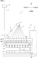
- a spun yarn take-up apparatus 1 is configured to wind synthetic fiber yarns Y spun out from a spinning apparatus 2 onto bobbins B, respectively, to form packages P.
- upward, downward, forward, and rearward directions shown in FIG. 1 will be referred to as upward, downward, forward, and rearward directions of the spun yarn take-up apparatus 1.
- the spun yarn take-up apparatus 1 includes godet rollers 3 and 4, an interlacing device 5, and a winding device 6.
- the spun yarn take-up apparatus 1 is provided below the spinning apparatus 2.
- the spinning apparatus 2 is configured to spin out synthetic fiber yarns Y downwardly through not-shown spinnerets.
- the synthetic fiber yarns Y are, for example, made of synthetic resin such as polyethylene terephthalate.
- the godet rollers 3 and 4 are rotationally driven by unillustrated motors, respectively.
- the yarns Y spun out from the spinning apparatus 2 are sent to the winding device 6 by the godet rollers 3 and 4.
- the interlacing device 5 is provided between the godet rollers 3 and 4.
- the interlacing device 5 is configured to interlace the yarns Y. The details of the interlacing device 5 will be given later.
- the winding device 6 is configured to wind the yarns Y sent from the godet roller 4 onto the bobbins B, respectively, to form packages P.
- the winding device 6 includes members such as a mount 11, a turret 12, two bobbin holders 13, a supporting frame 14, a contact roller 15, and a traverse unit 16.
- the turret 12 has a shape like a disc, and is attached to the mount 11.
- the turret 12 is rotationally driven by a motor which is not illustrated.
- the two long cylindrical bobbin holders 13 are cantilevered by the turret 12.
- the bobbin holders 13 extend in the front-rear direction.
- To each bobbin holder 13, the bobbins B are attached to be lined up along the axis of the bobbin holder 13.
- the two bobbin holders 13 at an upper winding position and a lower retracted position are replaceable by each other as the turret 12 rotates.
- the supporting frame 14 is a frame-shaped member which is long in the front-rear direction. This supporting frame 14 is fixed to the mount 11.
- a roller supporting member 17 which is long in the front-rear direction is attached to a lower part of the supporting frame 14 so as to be vertically movable relative to the supporting frame 14.
- the roller supporting member 17 supports the contact roller 15 in a rotatable manner.
- the contact roller 15 extends in the axial direction of the bobbin holders 13. As this contact roller 15 comes into contact with packages P, a predetermined contact pressure is applied to the packages P, so that the shape of the packages P is adjusted.
- the traverse unit 16 is provided immediately above the contact roller 15 of the roller supporting member 17.
- the traverse unit 16 includes traverse guides 16a lined up in the front-rear direction.
- the traverse guides 16a are driven by a motor (not illustrated) and are configured to reciprocate in the front-rear direction.
- a motor not illustrated
- the yarn Y is traversed in the front-rear direction about a corresponding fulcrum guide 18.
- the yarn Y is wound onto the corresponding bobbin B while being traversed, with the result that a package P is formed.
- the interlacing device 5 is configured to entangle a number of filaments constituting each yarn Y, to interlace the yarn Y.
- the interlacing device 5 includes an interlacing portion 21, two guide members 22, and a base 23.
- the interlacing portion 21 is structured by interlacing pieces 24 lined up in a predetermined arrangement direction so as to be adjacent to one another.
- a plurality of yarn running spaces 25 are disposed.
- Each yarn running space 25 is along a yarn running direction, which is orthogonal to the arrangement direction.
- a direction orthogonal to both the arrangement direction and the yarn running direction is defined as a height direction.
- the guide members 22 are respectively provided on upstream and downstream sides of the interlacing portion 21 with respect to the yarn running direction.
- Each guide member 22 is a comb-shaped guide including guide portions 22a lined up in the arrangement direction.
- the yarns Y are regulated by the guide portions 22a of the two guide members 22 so that the yarns Y run inside the respective yarn running spaces 25.
- the base 23 supports the interlacing portion 21 and the guide members 22.
- the interlacing pieces 24 and the guide members 22, with which the yarns Y come into contact, are made of ceramic.
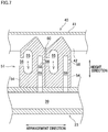
- FIG. 3 is a cross section of the interlacing portion 21. Specifically, FIG. 3 shows the cross section cut orthogonally to the yarn running direction at a middle portion of the interlacing portion 21 in the yarn running direction. For the sake of convenience, FIG. 3 shows only two adjacent interlacing pieces 24. The same applies to FIG. 7 .
- a second-side surface a left surface in FIG.
- each interlacing piece 24 which is on a second side relative to the arrangement direction, there is a second space 27 having a substantially rectangular cross sectional shape.
- the second space 27 extends throughout the interlacing piece 24 in the yarn running direction.
- the first space 26 and the second space 27 are substantially leveled with each other with respect to the height direction. Because of this, bringing two interlacing pieces 24 into contact with each other so as to be adjacent to each other in the arrangement direction causes the first space 26 of one of the interlacing pieces 24 to be combined with the second space 27 of the other of the interlacing pieces 24, to form a yarn running space 25.
- the cross sectional shapes of the first space 26 and the second space 27, and by extension, the cross sectional shape of the yarn running space 25 are not limited to those illustrated in FIG. 3 .
- Each interlacing piece 24 has a fluid ejection orifice 28 from which fluid is ejected to the corresponding yarn running space 25.
- the fluid ejection orifice 28 is positioned at a middle portion of the interlacing piece 24 in the yarn running direction, and is along the arrangement direction.
- a right end portion of the fluid ejection orifice 28 communicates with the yarn running space 25, and a left end portion of the fluid ejection orifice 28 communicates with a fluid supply hole 29.
- the fluid supply hole 29 is disposed in the interlacing piece 24 and is along the height direction.
- the fluid supply hole 29 communicates with a fluid passage 39 disposed in the base 23. Fluid supplied from an unillustrated fluid supply source passes through the fluid passage 39 and each fluid supply hole 29, and then the fluid is ejected to the yarn running space 25 through the fluid ejection orifice 28.
- a first-side surface (right surface in FIG. 3 ) of each interlacing piece 24 includes a leading-end-side portion (upper portion in FIG. 3 ), which is on a leading end side relative to the first space 26, and a base-end-side portion (lower portion in FIG. 3 ), which is on a base end side relative to the first space 26.
- the leading-end-side portion of the first-side surface is positioned slightly on the second side (to the left in FIG. 3 ) relative to the base-end-side portion of the first-side surface. Meanwhile, the second-side surface (left surface in FIG.
- each interlacing piece 24 includes a leading-end-side portion, which is on the leading end side relative to the second space 27, and a base-end-side portion, which is on the base end side relative to the second space 27.
- the leading-end-side portion of the second-side surface is flush with its base-end-side portion. Due to this structure, bringing two interlacing pieces 24 into contact with each other so as to be adjacent to each other in the arrangement direction forms a yarn insertion gap 30 between the two interlacing pieces 24.
- the yarn insertion gap 30 communicates with the yarn running space 25. This allows a yarn Y to be inserted into the yarn running space 25 through the yarn insertion gap 30.
- each interlacing piece 24 has a chevron shape, i.e., becomes narrower toward its leading end.
- fluid is supplied from the not-illustrated fluid supply source to the fluid passage 39.
- fluid compressed air is used, for example.
- the fluid supplied to the fluid passage 39 is ejected to each yarn running space 25 from the corresponding fluid ejection orifice 28 through the corresponding fluid supply hole 29.
- the fluid ejected to the yarn running space 25 creates a swirling flow in the yarn running space 25, and interlaces the yarn Y running through the yarn running space 25.
- the flow of the fluid ejected to the yarn running space 25 branches toward upstream and downstream sides in the yarn running direction, and the branch flows are respectively discharged from both ends of the yarn running space 25.
- each yarn running space 25 orthogonal to the yarn running direction is substantially symmetrical with respect to a central axis C of the corresponding fluid ejection orifice 28. Due to this, the fluid ejected from the fluid ejection orifice 28 creates, in the yarn running space 25, a swirling flow having symmetry with respect to the central axis C, and this preferably interlaces the yarn Y.
- each yarn running space 25 does not have to be shaped so as to be substantially symmetrical with respect to the central axis C of the fluid ejection orifice 28.
- each yarn running space 25 is sealed as tightly as possible except its openings at the both ends.
- each yarn insertion gap 30 is along the height direction crossing (orthogonal to) the central axis C of the fluid ejection orifice 28.
- a cover member 40 configured to cover the yarn insertion gaps 30.
- the cover member 40 is provided so as to cover the entire area of a leading-end-side portion of the interlacing portion 21.
- the cover member 40 includes a lid portion 41 and two yarn restricting portions 42, which are formed unitarily as one piece.
- the lid portion 41 is a flat-plate portion sized to have an area to cover the entire area of the interlacing portion 21.
- the yarn restricting portions 42 are parts bent approximately 90 degrees toward the base end side of the interlacing portion 21 (downward in FIG. 4 ) at both end portions of the lid portion 41 in the yarn running direction, respectively.
- the cover member 40 is provided so that: the lid portion 41 is positioned on the leading end side relative to the interlacing portion 21 with a small gap between them; and the two yarn restricting portions 42 are respectively disposed outward of (on the outer side of) both end faces of the interlacing portion 21 in the yarn running direction with a small gap between each yarn restricting portion 42 and the corresponding end face.
- the cover member 40 is provided so as not to be in contact with the interlacing portion 21, and this prevents damage to the interlacing portion 21.
- the tension of the yarns Y temporarily becomes zero to slacken the yarns Y.
- the slack yarns Y may come out through the yarn insertion gaps 30.
- Such coming-out yarns Y may be caught between the lid portion 41 and the interlacing portion 21 if the lid portion 41 is in contact with the interlacing portion 21.
- the yarns Y are not caught.
- each yarn restricting portion 42 is arranged to partially overlap the interlacing portion 21 when viewed from the yarn running direction.
- the yarns Y trying to come out of the interlacing portion 21 contact an end side of one or each of the yarn restricting portions 42. This reliably prevents the yarns Y from coming out of the interlacing portion 21.
- the thus provided yarn restricting portions 42 also reduce or minimize the entry of air from both end portions of each yarn introducing part 31 in the yarn running direction. It should be noted that during an interlacing process, tension is applied to the yarns Y, and therefore, basically, the yarns Y do not come out through the yarn insertion gaps 30.
- one end portion of the cover member 40 in the arrangement direction is supported by the base 23 so as to rotatable about a pivot axis 43. Due to this arrangement, the cover member 40 is movable between: a first position at which the cover member 40 covers the interlacing portion 21 as illustrated with solid lines in FIG. 6 ; and a second position at which the distance between the cover member 40 and the interlacing portion 21 is greater as illustrated with two-dot chain lines in FIG. 6 .
- a handle 44 is attached to the other end portion of the cover member 40 in the arrangement direction.
- the cover member 40 is configured to be easily movable between the first position and the second position by an operator using the handle 44.
- a sit portion 45 configured to be seated on a seat portion 23a provided on the base 23 is attached to the other end portion of the cover member 40 in the arrangement direction.
- the cover member 40 is at the first position, the sit portion 45 is seated on the seat portion 23a, and the cover member 40 is supported by the seat portion 23a.
- a magnet is provided on either one of the sit portion 45 and the seat portion 23a, and the other is made of magnetic material. This structure ensures that the sit portion 45 is kept seated.
- the above structure is not essential.
- the cover member 40 When the yarns Y are interlaced by the interlacing device 5, the cover member 40 is positioned at the first position. With this, the yarn insertion gaps 30 of the interlacing portion 21 are covered with the cover member 40. As a result, air is less likely to enter into the yarn running spaces 25 through the yarn insertion gaps 30, and this improve the interlacing capability.
- actual tests were conducted using 75 dtex/36 f yarns under the condition of the winding speed of 4900 mpm, to examine the difference in the number of knots per unit length between the situations in the presence and absence of the cover member 40. The results were as follows. The number of knots per unit length was 14.45 knots/m in the situation where the cover member 40 is not provided, while the number of knots increased to 16.58 knots/m in the situation where the cover member 40 is provided.
- the cover member 40 When the yarns Y are threaded onto the interlacing device 5, i.e., when the yarns Y are inserted into the yarn running spaces 25 through the yarn insertion gaps 30, the cover member 40 is moved to the second position. As a result, an open space S is created between the cover member 40 and the interlacing portion 21, and this allows the yarns Y to be inserted into the yarn insertion gaps 30 through the open space S. While in FIG. 6 , the cover member 40 is moved from the first position to the second position by an angle less than 90 degrees, the cover member 40 may be configured to be movable from the first position to the second position by an angle equal to or more than 90 degrees.
- the cover member 40 configured to cover the yarn insertion gaps 30 reduces or minimizes the entry of air into the yarn running spaces 25 through the yarn insertion gaps 30 during the interlacing process, and this makes it possible to improve the capability of interlacing the yarns Y.
- the cover member 40 is disposed at a position separated from the yarn running spaces 25, and therefore the yarns Y moving around in the yarn running spaces 25 during the interlacing process never come into contact with the cover member 40. Because of this, there is less limitation on the cover member 40, for example, the cover member 40 does not have to be made of ceramic. Furthermore, the cover member 40 does not have to undergo processing such as polishing in case of contact with the yarns Y. This leads to cost reduction of the cover member 40. Accordingly, it is possible to improve the interlacing capability by a low-cost structure.
- the cover member 40 includes the flat lid portion 41 configured to cover the yarn insertion gaps 30 at a position separated from the interlacing portion 21.
- the yarns Y are wound around bobbins B downstream of the interlacing device 5, to form packages P.
- the tension of the yarns Y temporarily becomes zero.
- the slack yarns Y may come out through the yarn insertion gaps 30.
- the lid portion 41 is in contact with the interlacing portion 21 in this situation, the coming-out yarns Y may be caught between the lid portion 41 and the interlacing portion 21.
- the lid portion 41 is separated from the interlacing portion 21, and this prevents the yarns Y from being caught.
- the cover member 40 further includes the yarn restricting portions 42 respectively disposed outward of the both end faces of the interlacing portion 21 in the yarn running direction, each yarn restricting portion 42 being provided so as to partially overlap the interlacing portion 21 when viewed from the yarn running direction.
- the above-described arrangement in which the lid portion 41 is separated from the interlacing portion 21 prevents the yarns Y from being caught.
- the yarns Y may greatly come out through the gap between the lid portion 41 and the interlacing portion 21.
- the above-mentioned yarn restricting portions 42 are provided to the cover member 40.
- the yarns Y trying to come out of the interlacing portion 21 contact the yarn restricting portions 42, and this reliably prevents the yarns Y from coming out. Note that such an event can occur only at the time of replacing the bobbins B, and the yarns Y are not always in contact with the yarn restricting portions 42. Because of this, the yarn restricting portions 42 do not have to be made of ceramic.
- each yarn running space 25 has a shape symmetrical with respect to the central axis C of the corresponding fluid ejection orifice 28, and each yarn insertion gap 30 is along a direction crossing the central axis C of the fluid ejection orifice 28.
- fluid flows symmetrically with respect to the central axis C of the fluid ejection orifice 28 in the yarn running space 25, and the flow of the fluid interlaces the yarn Y.
- the configuration of the present embodiment that is, to provide the cover member 40 configured to cover the yarn insertion gaps 30, is particularly effective.
- the cover member 40 is configured to be movable between: the first position at which the cover member 40 covers the yarn insertion gaps 30; and the second position at which the open space S is created between the cover member 40 and the interlacing portion 21 and the yarns Y are insertable into the yarn insertion gaps 30 through the open space S.
- the yarns Y are easily insertable into the yarn insertion gaps 30 by moving the cover member 40 from the first position to the second position. This enables rapid yarn threading to the interlacing device 5.
- the interlacing portion 21 is structured by the plurality of interlacing pieces 24 lined up in the arrangement direction orthogonal to the yarn running direction, the interlacing pieces 24 being shaped to provide the yarn running spaces 25 and the fluid ejection orifices 28; and the device is configured to interlace the yarns Y running through the yarn running spaces 25.
- the interlacing device 5 for multiple yarns Y it is possible to improve the capability of interlacing the multiple yarns Y by providing the cover member 40 configured to cover the entire area of the interlacing portion 21.
- Patent Literature 3 in which the yarn insertion gap is closed by the closure member.
- each yarn insertion gap 30 is formed between the corresponding two interlacing pieces 24 adjacent to each other in the arrangement direction. This arrangement eliminates the necessity of conducting cutting processing or the like to form the yarn insertion gaps 30 inside the interlacing pieces 24, and therefore the interlacing pieces 24 can be easily produced.
- each yarn running space 25 is formed by combining the first space 26 of one of the corresponding two interlacing pieces 24 adjacent to each other in the arrangement direction with the second space 27 of the other of the two interlacing pieces 24.
- the yarns Y moving around in the yarn running spaces 25 come into contact with the inner circumferential surfaces of the yarn running spaces 25. Because of this, in some cases, the inner circumferential surfaces undergo processing such as polishing to make the surfaces resistant to the contact with the yarns Y.
- the first space 26 and the second space 27 of the two interlacing pieces 24 of the above arrangement are exposed to the outside before the interlacing pieces 24 are lined up so as to be adjacent to one another. This allows the inner circumferential surfaces of the first space 26 and second space 27 to easily undergo processing such as polishing.
- the interlacing device 5 is for multiple yarns Y and is configured to interlace multiple yarns Y.
- the interlacing device 5 may be a device for a single yarn, which is configured to interlace a single yarn Y.
- the cover member 40 includes the lid portion 41 and the yarn restricting portions 42.
- the yarn restricting portions 42 do not have to be provided, as long as the cover member 40 is configured so that one or more slack yarns Y do not come out through the yarn insertion gaps 30.
- the cover member 40 does not have to be separated from the interlacing portion 21.
- a part of the cover member 40 may be in contact with the interlacing portion 21 as long as an arrangement is made to prevent one or more yarns Y from being caught between the cover member 40 and the interlacing portion 21.
- the lid portion 41 may be shaped so as to match with the chevron shape of the leading end portions of the interlacing pieces 24.
- the lid portion 41 and the yarn restricting portions 42 may be individual members, instead of formed unitarily as one piece.
- each yarn running space 25 has a shape symmetrical with respect to the central axis C of the corresponding fluid ejection orifice 28, and each yarn insertion gap 30 is along a direction crossing the central axis C of the corresponding fluid ejection orifice 28.
- the shapes of the yarn running spaces 25, fluid ejection orifices 28, and yarn insertion gaps 30, and their relative positional relationship are not limited to those described in the embodiment.
- the cover member 40 is configured to be movable between the first position and the second position. However, the cover member 40 does not have to be configured to be movable.
- the cover member 40 may be detachably attached at least to the interlacing portion 21.
- the cover member 40 may be detachably bolted to the interlacing portion 21, or may be detachably fitted to the interlacing portion 21 with the use of the elasticity of the material of the cover member 40.
- each yarn insertion gap 30 is formed between the corresponding two interlacing pieces 24 adjacent to each other in the arrangement direction.
- each yarn insertion gap 30 may be disposed in corresponding one of the interlacing pieces 24.
- each yarn running space 25 is formed by combining the first space 26 of one of the corresponding two interlacing pieces 24 adjacent to each other in the arrangement direction with the second space 27 of the other of the two interlacing pieces 24.
- the configuration of an interlacing portion 51 shown in FIG. 7 is also possible.
- each yarn running space 55 is disposed in corresponding one of interlacing pieces 54. The following will describe the structure of the interlacing portion 51.
- the interlacing portion 51 is structured by interlacing pieces 54 lined up in the arrangement direction so as to be adjacent to one another.
- each interlacing piece 54 there is a yarn running space 55 passing through the interlacing piece 54 in the yarn running direction.
- the cross sectional shape of the yarn running space 55 is elliptical with its longer axis extending in the height direction. In this regard, however, each yarn running space 55 may have another cross sectional shape.
- the yarn insertion space 56 is positioned at a level of a middle portion of the yarn running space 55 in the height direction.
- a right end portion of the yarn insertion space 56 communicates with the yarn running space 55.
- each interlacing piece 54 there is a fluid ejection orifice 58 from which fluid is ejected to the yarn running space 55 of its adjacent interlacing piece 54 on the right.
- the fluid ejection orifice 58 is positioned at a middle portion of the interlacing piece 54 in the yarn running direction, and is substantially level with the yarn insertion space 56 in the height direction.
- a right end portion of each fluid ejection orifice 58 communicates with the corresponding yarn insertion space 56, and a left end portion of each fluid ejection orifice 58 communicates with a fluid supply hole 59.
- the fluid supply hole 59 is disposed in the interlacing piece 54 and is along the height direction.
- the fluid supply hole 59 communicates with a fluid passage 39 provided in the base 23. Fluid supplied from an unillustrated fluid supply source passes through the fluid passage 39 and each fluid supply hole 59, and then the fluid is ejected to each yarn running space 55 through the corresponding fluid ejection orifice 58 and through the corresponding yarn insertion space 56.
- a left surface of each interlacing piece 54 includes a leading-end-side portion (upper portion in FIG. 7 ), which is on the leading end side relative to its yarn insertion space 56, and a base-end-side portion (lower portion in FIG. 7 ), which is on the base end side relative to the yarn insertion space 56.
- the leading-end-side portion of the left surface is positioned slightly to the right relative to the base-end-side portion of the left surface.
- the right surface of the interlacing piece 24 is a flat surface. Due to this structure, bringing two interlacing pieces 54 into contact with each other so as to be adjacent to each other in the arrangement direction forms a yarn insertion gap 60 between the two interlacing pieces 54.
- the cover member 40 configured to cover the yarn insertion gaps 60 may be provided similarly to the above-described embodiment, and this makes it possible to improve the interlacing capability.
Landscapes
- Physics & Mathematics (AREA)
- Fluid Mechanics (AREA)
- Engineering & Computer Science (AREA)
- Textile Engineering (AREA)
- Yarns And Mechanical Finishing Of Yarns Or Ropes (AREA)
Abstract
Description
- The present invention relates to an interlacing device configured to interlace one or more yarns using fluid.
- There have been known interlacing devices configured to interlace yarns using fluid. For example, Patent Literature 1 (Japanese Unexamined Patent Publication No.
2016-160550 - However, in Patent Literature 1, the interlacing portion has yarn insertion gaps through which yarns are inserted into the yarn running spaces. Air entering into the yarn running spaces through the yarn insertion gaps during an interlacing process may disturb the flow of the fluid in the yarn running spaces, leading to reduction in the interlacing capability. In this regard, an interlacing device described in Patent Literature 2 (Japanese Unexamined Patent Publication No.
2009-133018 DE 10038855 A1 ) is provided with a movable closure member configured to close a yarn insertion gap. - In practice, it is very difficult to bring the first and second members of
Patent Literature 2 into close contact with each other completely. If even a small gap exists, yarns may be caught in the gap, disadvantageously. To eliminate such a gap, contact surfaces of the members have to be mirror surfaces. However, this also brings about disadvantages such as an increase in cost due to mirror polishing, and an increase in probability of occurrence of yarn breakage due to the friction between the mirror surfaces and yarns contacting the surfaces when the yarns are synthetic fiber yarns. Meanwhile, inPatent Literature 3, the closure member faces the yarn running space, and therefore a yarn moving around in the yarn running space during an interlacing process comes into contact with the closure member. Because of this, the closure member has to be made of ceramic, for example, which increases its cost. - In view of the above problems, an object of the present invention is to improve interlacing capability by a low-cost structure.
- In an aspect of the present invention, an interlacing device includes an interlacing portion including: a yarn running space which is along a yarn running direction; and a fluid ejection orifice from which fluid is ejected to the yarn running space, the interlacing device being configured to interlace a yarn running through the yarn running space by fluid ejected from the fluid ejection orifice, wherein: the interlacing portion includes a yarn insertion gap through which the yarn is inserted into the yarn running space; and a cover member configured to cover the yarn insertion gap is disposed at a position separated from the yarn running space.
- In the above aspect of the present invention, the cover member configured to cover the yarn insertion gap reduces or minimizes the entry of air into the yarn running space through the yarn insertion gap during an interlacing process, and this makes it possible to improve the interlacing capability. Moreover, the cover member is disposed at a position separated from the yarn running space, and therefore the yarn moving around in the yarn running space during the interlacing process never comes into contact with the cover member. Due to this, there is no particular limitation on the material of the cover member. Furthermore, the cover member does not have to undergo processing such as polishing in case of contact with the yarn. This leads to cost reduction of the cover member. Accordingly, in the above aspect of the present invention, it is possible to improve the interlacing capability by a low-cost structure.
- In the above aspect of the present invention, it is preferable that the cover member includes a flat lid portion configured to cover the yarn insertion gap at a position separated from the interlacing portion.
- Suppose that the yarn is wound around a bobbin downstream of the interlacing device, to form a package. When the yarn is cut at the time of replacing a full bobbin with an empty bobbin, the tension of the yarn temporarily becomes zero. The reduction of the tension to zero slackens the yarn, and the slack yarn may come out through the yarn insertion gap. If the lid portion is in contact with the interlacing portion in this situation, the coming-out yarn may be caught between the lid portion and the interlacing portion. However, the lid portion is separated from the interlacing portion, and this prevents the yarn from being caught.
- In the above aspect of the present invention, it is preferable that the cover member further includes yarn restricting portions respectively disposed outward of both end faces of the interlacing portion in the yarn running direction, each yarn restricting portion being provided so as to partially overlap the interlacing portion when viewed from the yarn running direction.
- The above-described arrangement in which the lid portion is separated from the interlacing portion prevents the yarn from being caught. However, in this arrangement, the yarn may greatly come out through the gap between the lid portion and the interlacing portion. To deal with this, the above-mentioned yarn restricting portions are provided to the cover member. With this, the yarn trying to come out of the interlacing portion contacts one or each of the yarn restricting portions, and this reliably prevents the yarn from coming out.
- In the above aspect of the present invention, it is preferable that in a cross section orthogonal to the yarn running direction, the yarn running space has a shape symmetrical with respect to a central axis of the fluid ejection orifice, and the yarn insertion gap is along a direction crossing the central axis of the fluid ejection orifice.
- In the interlacing device structured as above, fluid flows symmetrically with respect to the central axis of the fluid ejection orifice in the yarn running space, and the flow of the fluid interlaces the yarn. In the arrangement where the yarn insertion gap is along a direction crossing the central axis of the fluid ejection orifice, however, air entering into the yarn running space through the yarn insertion gap may break the symmetry of the flow, and this tends to increase the degree of deterioration in the interlacing capability. In such a case, the configuration of the present invention, that is, to provide the cover member configured to cover the yarn insertion gap, is particularly effective.
- In the above aspect of the present invention, it is preferable that the cover member is configured to be movable between: a first position at which the cover member covers the yarn insertion gap; and a second position at which an open space is created between the cover member and the interlacing portion and the yarn is insertable into the yarn insertion gap through the open space.
- In the above arrangement, the yarn is easily insertable into the yarn insertion gap by moving the cover member from the first position to the second position. This enables rapid yarn threading to the interlacing device.
- In the above aspect of the present invention, it is preferable that: the yarn running space includes a plurality of yarn running spaces and the fluid ejection orifice includes a plurality of fluid ejection orifices, and the interlacing portion is structured by a plurality of interlacing pieces lined up in an arrangement direction orthogonal to the yarn running direction, the interlacing pieces being shaped to provide the yarn running spaces and the fluid ejection orifices; and the interlacing device is configured to interlace a plurality of yarns running through the yarn running spaces.
- With respect to such an interlacing device for multiple yarns, it is possible to improve the capability of interlacing multiple yarns by providing the cover member configured to cover the entire area of the interlacing portion. For example, reference is made to the above-mentioned
Patent Literature 3, in which the yarn insertion gap is closed by the closure member. If this configuration is applied to the interlacing device for multiple yarns, a plurality of closure members have to be provided, which greatly increases the cost. In this regard, however, in the above aspect of the present invention, it is only required to provide the single cover member, and therefore the cost of the structure is effectively lowered. - In the above aspect of the present invention, it is preferable that the yarn insertion gap is formed between two adjacent interlacing pieces of the interlacing pieces, which are adjacent to each other in the arrangement direction.
- This arrangement eliminates the necessity of conducting cutting processing or the like to form the yarn insertion gap inside the interlacing piece, and therefore the interlacing pieces can be easily produced.
- In the above aspect of the present invention, it is preferable that each yarn running space is formed by combining a first space of one of the corresponding two interlacing pieces adjacent to each other in the arrangement direction with a second space of the other of the two interlacing pieces.
- During the interlacing process, the yarns moving around in the yarn running spaces come into contact with inner circumferential surfaces of the yarn running spaces. Because of this, in some cases, the inner circumferential surfaces undergo processing such as polishing to make the surfaces resistant to the contact with the yarns. In such a case, the first space and the second space of the interlacing pieces of the above arrangement are exposed to the outside before the interlacing pieces are lined up so as to be adjacent to one another. This allows the inner circumferential surfaces of the first and second spaces to easily undergo processing such as polishing.
-
-
FIG. 1 is a side view of an example of a spun yarn take-up apparatus including an interlacing device related to an embodiment of the present invention. -
FIG. 2 is a perspective view of the interlacing device. -
FIG. 3 is a cross section of an interlacing portion. -
FIG. 4 is a perspective view of the interlacing device with a cover member. -
FIG. 5 shows the interlacing portion viewed from a direction V ofFIG. 3 . -
FIG. 6 is a side view illustrating how the cover member moves. -
FIG. 7 is a cross section of an interlacing portion of a modification. - The following will describe an embodiment of an interlacing device related to the present invention. As shown in
FIG. 1 , a spun yarn take-up apparatus 1 is configured to wind synthetic fiber yarns Y spun out from aspinning apparatus 2 onto bobbins B, respectively, to form packages P. In the present embodiment, upward, downward, forward, and rearward directions shown inFIG. 1 will be referred to as upward, downward, forward, and rearward directions of the spun yarn take-up apparatus 1. - The spun yarn take-up apparatus 1 includes
godet rollers device 5, and a windingdevice 6. The spun yarn take-up apparatus 1 is provided below thespinning apparatus 2. Thespinning apparatus 2 is configured to spin out synthetic fiber yarns Y downwardly through not-shown spinnerets. The synthetic fiber yarns Y are, for example, made of synthetic resin such as polyethylene terephthalate. Thegodet rollers spinning apparatus 2 are sent to the windingdevice 6 by thegodet rollers device 5 is provided between thegodet rollers device 5 is configured to interlace the yarns Y. The details of the interlacingdevice 5 will be given later. - The winding
device 6 is configured to wind the yarns Y sent from thegodet roller 4 onto the bobbins B, respectively, to form packages P. The windingdevice 6 includes members such as amount 11, aturret 12, twobobbin holders 13, a supportingframe 14, acontact roller 15, and atraverse unit 16. - The
turret 12 has a shape like a disc, and is attached to themount 11. Theturret 12 is rotationally driven by a motor which is not illustrated. The two longcylindrical bobbin holders 13 are cantilevered by theturret 12. Thebobbin holders 13 extend in the front-rear direction. To eachbobbin holder 13, the bobbins B are attached to be lined up along the axis of thebobbin holder 13. The twobobbin holders 13 at an upper winding position and a lower retracted position are replaceable by each other as theturret 12 rotates. - The supporting
frame 14 is a frame-shaped member which is long in the front-rear direction. This supportingframe 14 is fixed to themount 11. Aroller supporting member 17 which is long in the front-rear direction is attached to a lower part of the supportingframe 14 so as to be vertically movable relative to the supportingframe 14. Theroller supporting member 17 supports thecontact roller 15 in a rotatable manner. Thecontact roller 15 extends in the axial direction of thebobbin holders 13. As thiscontact roller 15 comes into contact with packages P, a predetermined contact pressure is applied to the packages P, so that the shape of the packages P is adjusted. - The
traverse unit 16 is provided immediately above thecontact roller 15 of theroller supporting member 17. Thetraverse unit 16 includes traverse guides 16a lined up in the front-rear direction. The traverse guides 16a are driven by a motor (not illustrated) and are configured to reciprocate in the front-rear direction. As eachtraverse guide 16a holding the corresponding yarn Y reciprocates, the yarn Y is traversed in the front-rear direction about acorresponding fulcrum guide 18. The yarn Y is wound onto the corresponding bobbin B while being traversed, with the result that a package P is formed. - Now, the interlacing
device 5 will be detailed. The interlacingdevice 5 is configured to entangle a number of filaments constituting each yarn Y, to interlace the yarn Y. As shown inFIG. 2 , the interlacingdevice 5 includes an interlacingportion 21, twoguide members 22, and abase 23. The interlacingportion 21 is structured by interlacingpieces 24 lined up in a predetermined arrangement direction so as to be adjacent to one another. In the interlacingportion 21, a plurality ofyarn running spaces 25 are disposed. Eachyarn running space 25 is along a yarn running direction, which is orthogonal to the arrangement direction. In the present embodiment, a direction orthogonal to both the arrangement direction and the yarn running direction is defined as a height direction. - The
guide members 22 are respectively provided on upstream and downstream sides of the interlacingportion 21 with respect to the yarn running direction. Eachguide member 22 is a comb-shaped guide includingguide portions 22a lined up in the arrangement direction. The yarns Y are regulated by theguide portions 22a of the twoguide members 22 so that the yarns Y run inside the respectiveyarn running spaces 25. Thebase 23 supports the interlacingportion 21 and theguide members 22. The interlacingpieces 24 and theguide members 22, with which the yarns Y come into contact, are made of ceramic. -
FIG. 3 is a cross section of the interlacingportion 21. Specifically,FIG. 3 shows the cross section cut orthogonally to the yarn running direction at a middle portion of the interlacingportion 21 in the yarn running direction. For the sake of convenience,FIG. 3 shows only two adjacent interlacingpieces 24. The same applies toFIG. 7 . On a first-side surface (a right surface inFIG. 3 ) of each interlacingpiece 24, which is on a first side relative to the arrangement direction, there is afirst space 26 having a substantially triangular cross sectional shape. Thefirst space 26 extends throughout the interlacingpiece 24 in the yarn running direction. Meanwhile, on a second-side surface (a left surface inFIG. 3 ) of each interlacingpiece 24, which is on a second side relative to the arrangement direction, there is asecond space 27 having a substantially rectangular cross sectional shape. Thesecond space 27 extends throughout the interlacingpiece 24 in the yarn running direction. Thefirst space 26 and thesecond space 27 are substantially leveled with each other with respect to the height direction. Because of this, bringing two interlacingpieces 24 into contact with each other so as to be adjacent to each other in the arrangement direction causes thefirst space 26 of one of the interlacingpieces 24 to be combined with thesecond space 27 of the other of the interlacingpieces 24, to form ayarn running space 25. It should be noted that the cross sectional shapes of thefirst space 26 and thesecond space 27, and by extension, the cross sectional shape of theyarn running space 25 are not limited to those illustrated inFIG. 3 . - Each interlacing
piece 24 has afluid ejection orifice 28 from which fluid is ejected to the correspondingyarn running space 25. Thefluid ejection orifice 28 is positioned at a middle portion of the interlacingpiece 24 in the yarn running direction, and is along the arrangement direction. A right end portion of thefluid ejection orifice 28 communicates with theyarn running space 25, and a left end portion of thefluid ejection orifice 28 communicates with afluid supply hole 29. Thefluid supply hole 29 is disposed in the interlacingpiece 24 and is along the height direction. Thefluid supply hole 29 communicates with afluid passage 39 disposed in thebase 23. Fluid supplied from an unillustrated fluid supply source passes through thefluid passage 39 and eachfluid supply hole 29, and then the fluid is ejected to theyarn running space 25 through thefluid ejection orifice 28. - A first-side surface (right surface in
FIG. 3 ) of each interlacingpiece 24 includes a leading-end-side portion (upper portion inFIG. 3 ), which is on a leading end side relative to thefirst space 26, and a base-end-side portion (lower portion inFIG. 3 ), which is on a base end side relative to thefirst space 26. The leading-end-side portion of the first-side surface is positioned slightly on the second side (to the left inFIG. 3 ) relative to the base-end-side portion of the first-side surface. Meanwhile, the second-side surface (left surface inFIG. 3 ) of each interlacingpiece 24 includes a leading-end-side portion, which is on the leading end side relative to thesecond space 27, and a base-end-side portion, which is on the base end side relative to thesecond space 27. The leading-end-side portion of the second-side surface is flush with its base-end-side portion. Due to this structure, bringing two interlacingpieces 24 into contact with each other so as to be adjacent to each other in the arrangement direction forms ayarn insertion gap 30 between the two interlacingpieces 24. Theyarn insertion gap 30 communicates with theyarn running space 25. This allows a yarn Y to be inserted into theyarn running space 25 through theyarn insertion gap 30. Furthermore, a leading end portion of each interlacingpiece 24 has a chevron shape, i.e., becomes narrower toward its leading end. This creates ayarn introducing part 31 having a cross sectional shape of an inverted triangle between the leading end portions of the two interlacingpieces 24. Inclined surfaces defining theyarn introducing part 31 makes it possible to easily guide the corresponding yarn Y into the correspondingyarn insertion gap 30. - To interlace the yarns Y running through the respective
yarn running spaces 25, fluid is supplied from the not-illustrated fluid supply source to thefluid passage 39. As such fluid, compressed air is used, for example. The fluid supplied to thefluid passage 39 is ejected to eachyarn running space 25 from the correspondingfluid ejection orifice 28 through the correspondingfluid supply hole 29. The fluid ejected to theyarn running space 25 creates a swirling flow in theyarn running space 25, and interlaces the yarn Y running through theyarn running space 25. The flow of the fluid ejected to theyarn running space 25 branches toward upstream and downstream sides in the yarn running direction, and the branch flows are respectively discharged from both ends of theyarn running space 25. - As shown in
FIG. 3 , in the present embodiment, the cross section of eachyarn running space 25 orthogonal to the yarn running direction is substantially symmetrical with respect to a central axis C of the correspondingfluid ejection orifice 28. Due to this, the fluid ejected from thefluid ejection orifice 28 creates, in theyarn running space 25, a swirling flow having symmetry with respect to the central axis C, and this preferably interlaces the yarn Y. Provided however, eachyarn running space 25 does not have to be shaped so as to be substantially symmetrical with respect to the central axis C of thefluid ejection orifice 28. - Now, in the arrangement in which each yarn Y is interlaced by the above-mentioned swirling flow, it is preferable that each
yarn running space 25 is sealed as tightly as possible except its openings at the both ends. However, in the present embodiment, there is theyarn insertion gap 30 through which the yarn Y is inserted into theyarn running space 25, and therefore air enters into theyarn running space 25 through theyarn insertion gap 30. Such entering air may disturb the flow of the fluid in theyarn running space 25, leading to reduction in the interlacing capability. Particularly, in the present embodiment, eachyarn insertion gap 30 is along the height direction crossing (orthogonal to) the central axis C of thefluid ejection orifice 28. In this configuration, there would be a possibility that air entering into eachyarn running space 25 thorough the correspondingyarn insertion gap 30 breaks the symmetry of the fluid flow with respect to the central axis C and significantly reduces the interlacing capability. In the present embodiment, to reduce the entry of air into theyarn running spaces 25 through theyarn insertion gaps 30, there is provided acover member 40 configured to cover theyarn insertion gaps 30. - As shown in
FIG. 4 , thecover member 40 is provided so as to cover the entire area of a leading-end-side portion of the interlacingportion 21. Thecover member 40 includes alid portion 41 and twoyarn restricting portions 42, which are formed unitarily as one piece. Thelid portion 41 is a flat-plate portion sized to have an area to cover the entire area of the interlacingportion 21. Theyarn restricting portions 42 are parts bent approximately 90 degrees toward the base end side of the interlacing portion 21 (downward inFIG. 4 ) at both end portions of thelid portion 41 in the yarn running direction, respectively. - As shown in
FIG. 5 , thecover member 40 is provided so that: thelid portion 41 is positioned on the leading end side relative to the interlacingportion 21 with a small gap between them; and the twoyarn restricting portions 42 are respectively disposed outward of (on the outer side of) both end faces of the interlacingportion 21 in the yarn running direction with a small gap between eachyarn restricting portion 42 and the corresponding end face. As such, thecover member 40 is provided so as not to be in contact with the interlacingportion 21, and this prevents damage to the interlacingportion 21. When cutting the yarns Y at the time of replacing the full bobbins B with empty bobbins B by rotating the turret 12 (seeFIG. 1 ), the tension of the yarns Y temporarily becomes zero to slacken the yarns Y. The slack yarns Y may come out through theyarn insertion gaps 30. Such coming-out yarns Y may be caught between thelid portion 41 and the interlacingportion 21 if thelid portion 41 is in contact with the interlacingportion 21. However, because thelid portion 41 is separated from the interlacingportion 21, the yarns Y are not caught. - However, in the arrangement in which the
lid portion 41 is separated from the interlacingportion 21, there is a possibility that the yarns Y greatly come out through the gap between thelid portion 41 and the interlacingportion 21. To deal with this, in the present embodiment, as shown inFIG. 3 , eachyarn restricting portion 42 is arranged to partially overlap the interlacingportion 21 when viewed from the yarn running direction. In this arrangement, the yarns Y trying to come out of the interlacingportion 21 contact an end side of one or each of theyarn restricting portions 42. This reliably prevents the yarns Y from coming out of the interlacingportion 21. Furthermore, the thus providedyarn restricting portions 42 also reduce or minimize the entry of air from both end portions of eachyarn introducing part 31 in the yarn running direction. It should be noted that during an interlacing process, tension is applied to the yarns Y, and therefore, basically, the yarns Y do not come out through theyarn insertion gaps 30. - As shown in
FIG. 6 , one end portion of thecover member 40 in the arrangement direction is supported by the base 23 so as to rotatable about apivot axis 43. Due to this arrangement, thecover member 40 is movable between: a first position at which thecover member 40 covers the interlacingportion 21 as illustrated with solid lines inFIG. 6 ; and a second position at which the distance between thecover member 40 and the interlacingportion 21 is greater as illustrated with two-dot chain lines inFIG. 6 . Ahandle 44 is attached to the other end portion of thecover member 40 in the arrangement direction. Thecover member 40 is configured to be easily movable between the first position and the second position by an operator using thehandle 44. - Furthermore, a
sit portion 45 configured to be seated on aseat portion 23a provided on thebase 23 is attached to the other end portion of thecover member 40 in the arrangement direction. When thecover member 40 is at the first position, thesit portion 45 is seated on theseat portion 23a, and thecover member 40 is supported by theseat portion 23a. In the present embodiment, a magnet is provided on either one of thesit portion 45 and theseat portion 23a, and the other is made of magnetic material. This structure ensures that thesit portion 45 is kept seated. However, the above structure is not essential. - When the yarns Y are interlaced by the interlacing
device 5, thecover member 40 is positioned at the first position. With this, theyarn insertion gaps 30 of the interlacingportion 21 are covered with thecover member 40. As a result, air is less likely to enter into theyarn running spaces 25 through theyarn insertion gaps 30, and this improve the interlacing capability. In this regard, actual tests were conducted using 75 dtex/36 f yarns under the condition of the winding speed of 4900 mpm, to examine the difference in the number of knots per unit length between the situations in the presence and absence of thecover member 40. The results were as follows. The number of knots per unit length was 14.45 knots/m in the situation where thecover member 40 is not provided, while the number of knots increased to 16.58 knots/m in the situation where thecover member 40 is provided. - When the yarns Y are threaded onto the interlacing
device 5, i.e., when the yarns Y are inserted into theyarn running spaces 25 through theyarn insertion gaps 30, thecover member 40 is moved to the second position. As a result, an open space S is created between thecover member 40 and the interlacingportion 21, and this allows the yarns Y to be inserted into theyarn insertion gaps 30 through the open space S. While inFIG. 6 , thecover member 40 is moved from the first position to the second position by an angle less than 90 degrees, thecover member 40 may be configured to be movable from the first position to the second position by an angle equal to or more than 90 degrees. - In the present embodiment, the
cover member 40 configured to cover theyarn insertion gaps 30 reduces or minimizes the entry of air into theyarn running spaces 25 through theyarn insertion gaps 30 during the interlacing process, and this makes it possible to improve the capability of interlacing the yarns Y. Moreover, in the present embodiment, thecover member 40 is disposed at a position separated from theyarn running spaces 25, and therefore the yarns Y moving around in theyarn running spaces 25 during the interlacing process never come into contact with thecover member 40. Because of this, there is less limitation on thecover member 40, for example, thecover member 40 does not have to be made of ceramic. Furthermore, thecover member 40 does not have to undergo processing such as polishing in case of contact with the yarns Y. This leads to cost reduction of thecover member 40. Accordingly, it is possible to improve the interlacing capability by a low-cost structure. - In the present embodiment, the
cover member 40 includes theflat lid portion 41 configured to cover theyarn insertion gaps 30 at a position separated from the interlacingportion 21. Suppose that the yarns Y are wound around bobbins B downstream of the interlacingdevice 5, to form packages P. When the yarns Y are cut at the time of replacing full bobbins B with empty bobbins B, the tension of the yarns Y temporarily becomes zero. As a result, the slack yarns Y may come out through theyarn insertion gaps 30. If thelid portion 41 is in contact with the interlacingportion 21 in this situation, the coming-out yarns Y may be caught between thelid portion 41 and the interlacingportion 21. However, thelid portion 41 is separated from the interlacingportion 21, and this prevents the yarns Y from being caught. - In the present embodiment, the
cover member 40 further includes theyarn restricting portions 42 respectively disposed outward of the both end faces of the interlacingportion 21 in the yarn running direction, eachyarn restricting portion 42 being provided so as to partially overlap the interlacingportion 21 when viewed from the yarn running direction. The above-described arrangement in which thelid portion 41 is separated from the interlacingportion 21 prevents the yarns Y from being caught. However, in this arrangement, the yarns Y may greatly come out through the gap between thelid portion 41 and the interlacingportion 21. To deal with this, the above-mentionedyarn restricting portions 42 are provided to thecover member 40. With this, the yarns Y trying to come out of the interlacingportion 21 contact theyarn restricting portions 42, and this reliably prevents the yarns Y from coming out. Note that such an event can occur only at the time of replacing the bobbins B, and the yarns Y are not always in contact with theyarn restricting portions 42. Because of this, theyarn restricting portions 42 do not have to be made of ceramic. - In the present embodiment, in a cross section orthogonal to the yarn running direction, each
yarn running space 25 has a shape symmetrical with respect to the central axis C of the correspondingfluid ejection orifice 28, and eachyarn insertion gap 30 is along a direction crossing the central axis C of thefluid ejection orifice 28. In the interlacingdevice 5 structured as above, fluid flows symmetrically with respect to the central axis C of thefluid ejection orifice 28 in theyarn running space 25, and the flow of the fluid interlaces the yarn Y. In the arrangement where theyarn insertion gap 30 is along a direction crossing the central axis C, however, air entering into theyarn running space 25 through theyarn insertion gap 30 may break the symmetry of the flow, and this tends to increase the degree of deterioration in the interlacing capability. In such a case, the configuration of the present embodiment, that is, to provide thecover member 40 configured to cover theyarn insertion gaps 30, is particularly effective. - In the present embodiment, the
cover member 40 is configured to be movable between: the first position at which thecover member 40 covers theyarn insertion gaps 30; and the second position at which the open space S is created between thecover member 40 and the interlacingportion 21 and the yarns Y are insertable into theyarn insertion gaps 30 through the open space S. In the above arrangement, the yarns Y are easily insertable into theyarn insertion gaps 30 by moving thecover member 40 from the first position to the second position. This enables rapid yarn threading to the interlacingdevice 5. - In the present embodiment, the interlacing
portion 21 is structured by the plurality of interlacingpieces 24 lined up in the arrangement direction orthogonal to the yarn running direction, the interlacingpieces 24 being shaped to provide theyarn running spaces 25 and thefluid ejection orifices 28; and the device is configured to interlace the yarns Y running through theyarn running spaces 25. With respect to the interlacingdevice 5 for multiple yarns Y, it is possible to improve the capability of interlacing the multiple yarns Y by providing thecover member 40 configured to cover the entire area of the interlacingportion 21. For example, reference is made to the above-mentionedPatent Literature 3, in which the yarn insertion gap is closed by the closure member. If this configuration is applied to the interlacing device for multiple yarns, a plurality of closure members have to be provided, which greatly increases the cost. In this regard, however, in the present embodiment, it is only required to provide thesingle cover member 40, and therefore the cost of the structure is effectively lowered. - In the present embodiment, each
yarn insertion gap 30 is formed between the corresponding two interlacingpieces 24 adjacent to each other in the arrangement direction. This arrangement eliminates the necessity of conducting cutting processing or the like to form theyarn insertion gaps 30 inside the interlacingpieces 24, and therefore the interlacingpieces 24 can be easily produced. - In the present embodiment, each
yarn running space 25 is formed by combining thefirst space 26 of one of the corresponding two interlacingpieces 24 adjacent to each other in the arrangement direction with thesecond space 27 of the other of the two interlacingpieces 24. During the interlacing process, the yarns Y moving around in theyarn running spaces 25 come into contact with the inner circumferential surfaces of theyarn running spaces 25. Because of this, in some cases, the inner circumferential surfaces undergo processing such as polishing to make the surfaces resistant to the contact with the yarns Y. In such a case, thefirst space 26 and thesecond space 27 of the two interlacingpieces 24 of the above arrangement are exposed to the outside before the interlacingpieces 24 are lined up so as to be adjacent to one another. This allows the inner circumferential surfaces of thefirst space 26 andsecond space 27 to easily undergo processing such as polishing. - The following will describe modifications of the above-described embodiment.
- In the above-described embodiment, the interlacing
device 5 is for multiple yarns Y and is configured to interlace multiple yarns Y. However, the interlacingdevice 5 may be a device for a single yarn, which is configured to interlace a single yarn Y. - In the above-described embodiment, the
cover member 40 includes thelid portion 41 and theyarn restricting portions 42. However, theyarn restricting portions 42 do not have to be provided, as long as thecover member 40 is configured so that one or more slack yarns Y do not come out through theyarn insertion gaps 30. Furthermore, thecover member 40 does not have to be separated from the interlacingportion 21. A part of thecover member 40 may be in contact with the interlacingportion 21 as long as an arrangement is made to prevent one or more yarns Y from being caught between thecover member 40 and the interlacingportion 21. Furthermore, thelid portion 41 may be shaped so as to match with the chevron shape of the leading end portions of the interlacingpieces 24. Still further, thelid portion 41 and theyarn restricting portions 42 may be individual members, instead of formed unitarily as one piece. - In the above-described embodiment, each
yarn running space 25 has a shape symmetrical with respect to the central axis C of the correspondingfluid ejection orifice 28, and eachyarn insertion gap 30 is along a direction crossing the central axis C of the correspondingfluid ejection orifice 28. However, the shapes of theyarn running spaces 25,fluid ejection orifices 28, andyarn insertion gaps 30, and their relative positional relationship are not limited to those described in the embodiment. - In the above-described embodiment, the
cover member 40 is configured to be movable between the first position and the second position. However, thecover member 40 does not have to be configured to be movable. Thecover member 40 may be detachably attached at least to the interlacingportion 21. For example, thecover member 40 may be detachably bolted to the interlacingportion 21, or may be detachably fitted to the interlacingportion 21 with the use of the elasticity of the material of thecover member 40. - In the above-described embodiment, each
yarn insertion gap 30 is formed between the corresponding two interlacingpieces 24 adjacent to each other in the arrangement direction. However, eachyarn insertion gap 30 may be disposed in corresponding one of the interlacingpieces 24. - In the above-described embodiment, each
yarn running space 25 is formed by combining thefirst space 26 of one of the corresponding two interlacingpieces 24 adjacent to each other in the arrangement direction with thesecond space 27 of the other of the two interlacingpieces 24. In this regard, however, the configuration of an interlacingportion 51 shown inFIG. 7 is also possible. In the interlacingportion 51, each yarn running space 55 is disposed in corresponding one of interlacingpieces 54. The following will describe the structure of the interlacingportion 51. - The interlacing
portion 51 is structured by interlacingpieces 54 lined up in the arrangement direction so as to be adjacent to one another. In each interlacingpiece 54, there is a yarn running space 55 passing through the interlacingpiece 54 in the yarn running direction. The cross sectional shape of the yarn running space 55 is elliptical with its longer axis extending in the height direction. In this regard, however, each yarn running space 55 may have another cross sectional shape. To the left of each yarn running space 55, there is a yarn insertion space 56 extending throughout the interlacingpiece 54 in the yarn running direction. The yarn insertion space 56 is positioned at a level of a middle portion of the yarn running space 55 in the height direction. A right end portion of the yarn insertion space 56 communicates with the yarn running space 55. - At a right end portion of each interlacing
piece 54, there is afluid ejection orifice 58 from which fluid is ejected to the yarn running space 55 of itsadjacent interlacing piece 54 on the right. Thefluid ejection orifice 58 is positioned at a middle portion of the interlacingpiece 54 in the yarn running direction, and is substantially level with the yarn insertion space 56 in the height direction. A right end portion of eachfluid ejection orifice 58 communicates with the corresponding yarn insertion space 56, and a left end portion of eachfluid ejection orifice 58 communicates with afluid supply hole 59. Thefluid supply hole 59 is disposed in the interlacingpiece 54 and is along the height direction. Thefluid supply hole 59 communicates with afluid passage 39 provided in thebase 23. Fluid supplied from an unillustrated fluid supply source passes through thefluid passage 39 and eachfluid supply hole 59, and then the fluid is ejected to each yarn running space 55 through the correspondingfluid ejection orifice 58 and through the corresponding yarn insertion space 56. - A left surface of each interlacing
piece 54 includes a leading-end-side portion (upper portion inFIG. 7 ), which is on the leading end side relative to its yarn insertion space 56, and a base-end-side portion (lower portion inFIG. 7 ), which is on the base end side relative to the yarn insertion space 56. The leading-end-side portion of the left surface is positioned slightly to the right relative to the base-end-side portion of the left surface. Meanwhile, the right surface of the interlacingpiece 24 is a flat surface. Due to this structure, bringing two interlacingpieces 54 into contact with each other so as to be adjacent to each other in the arrangement direction forms ayarn insertion gap 60 between the two interlacingpieces 54. Because theyarn insertion gap 60 communicates with the corresponding yarn running space 55 through the corresponding yarn insertion space 56, the yarn Y is insertable into the yarn running space 55 through theyarn insertion gap 60. With respect to the interlacingportion 51 structured as above, thecover member 40 configured to cover theyarn insertion gaps 60 may be provided similarly to the above-described embodiment, and this makes it possible to improve the interlacing capability.
Claims (8)
- An interlacing device comprising
an interlacing portion including: a yarn running space which is along a yarn running direction; and a fluid ejection orifice from which fluid is ejected to the yarn running space, the interlacing device being configured to interlace a yarn running through the yarn running space by fluid ejected from the fluid ejection orifice, wherein:the interlacing portion includes a yarn insertion gap through which the yarn is inserted into the yarn running space; anda cover member configured to cover the yarn insertion gap is disposed at a position separated from the yarn running space. - The interlacing device according to claim 1, wherein the cover member includes a flat lid portion configured to cover the yarn insertion gap at a position separated from the interlacing portion.
- The interlacing device according to claim 2, wherein the cover member further includes yarn restricting portions respectively disposed outward of both end faces of the interlacing portion in the yarn running direction, each yarn restricting portion being provided so as to partially overlap the interlacing portion when viewed from the yarn running direction.
- The interlacing device according to any one of claims 1 to 3, wherein in a cross section orthogonal to the yarn running direction, the yarn running space has a shape symmetrical with respect to a central axis of the fluid ejection orifice, and the yarn insertion gap is along a direction crossing the central axis of the fluid ejection orifice.
- The interlacing device according to any one of claims 1 to 4, wherein the cover member is configured to be movable between: a first position at which the cover member covers the yarn insertion gap; and a second position at which an open space is created between the cover member and the interlacing portion and the yarn is insertable into the yarn insertion gap through the open space.
- The interlacing device according to any one of claims 1 to 5, wherein:
the yarn running space includes a plurality of yarn running spaces and the fluid ejection orifice includes a plurality of fluid ejection orifices, and the interlacing portion is structured by a plurality of interlacing pieces lined up in an arrangement direction orthogonal to the yarn running direction, the interlacing pieces being shaped to provide the yarn running spaces and the fluid ejection orifices; and the interlacing device is configured to interlace a plurality of yarns running through the yarn running spaces. - The interlacing device according to claim 6, wherein the yarn insertion gap is formed between two adjacent interlacing pieces of the interlacing pieces, which are adjacent to each other in the arrangement direction.
- The interlacing device according to claim 6 or 7, wherein each yarn running space is formed by combining a first space of one of the corresponding two interlacing pieces adjacent to each other in the arrangement direction with a second space of the other of the two interlacing pieces.
Applications Claiming Priority (1)
| Application Number | Priority Date | Filing Date | Title |
|---|---|---|---|
| JP2017158024A JP6981808B2 (en) | 2017-08-18 | 2017-08-18 | Confounding device |
Publications (2)
| Publication Number | Publication Date |
|---|---|
| EP3444389A1 true EP3444389A1 (en) | 2019-02-20 |
| EP3444389B1 EP3444389B1 (en) | 2020-10-28 |
Family
ID=62816352
Family Applications (1)
| Application Number | Title | Priority Date | Filing Date |
|---|---|---|---|
| EP18180367.7A Active EP3444389B1 (en) | 2017-08-18 | 2018-06-28 | Interlacing device |
Country Status (3)
| Country | Link |
|---|---|
| EP (1) | EP3444389B1 (en) |
| JP (1) | JP6981808B2 (en) |
| CN (1) | CN109402824B (en) |
Families Citing this family (4)
| Publication number | Priority date | Publication date | Assignee | Title |
|---|---|---|---|---|
| JP7642482B2 (en) * | 2021-08-05 | 2025-03-10 | Tmtマシナリー株式会社 | Yarn processing mechanism and spinning take-up device |
| JP7715567B2 (en) * | 2021-08-05 | 2025-07-30 | Tmtマシナリー株式会社 | Yarn processing mechanism and spinning take-up device |
| CN115233325B (en) * | 2022-09-23 | 2022-12-16 | 江苏恒力化纤股份有限公司 | Method for producing low-broken-yarn-rate profiled fibers by polyester FDY (fully drawn yarn) process |
| JP2025116816A (en) | 2024-01-29 | 2025-08-08 | Tmtマシナリー株式会社 | Interlacing device and spinning take-up machine |
Citations (6)
| Publication number | Priority date | Publication date | Assignee | Title |
|---|---|---|---|---|
| GB1463238A (en) * | 1974-04-26 | 1977-02-02 | Schwarza Chemiefaser | Apparatus for consolidating threads |
| DE10038855A1 (en) | 1999-08-04 | 2001-03-29 | Temco Textilmaschkomponent | Jet body for continuous interlacing of texturized or smooth multifilament yarns has an opening along the body into the yarn channel for the yarns to be laid and closed by a swing jet segment to avoid threading through |
| JP2009133018A (en) | 2007-11-29 | 2009-06-18 | Tmt Machinery Inc | Multi-thread entanglement device |
| CN201530898U (en) * | 2009-10-23 | 2010-07-21 | 陈燕 | Improved structure of cover plate type tangle jet |
| US20100257710A1 (en) * | 2007-07-25 | 2010-10-14 | Stuendl Mathias | Apparatus for treating a multifilament thread |
| JP2016160550A (en) | 2015-03-02 | 2016-09-05 | Tmtマシナリー株式会社 | Interlacing device |
Family Cites Families (6)
| Publication number | Priority date | Publication date | Assignee | Title |
|---|---|---|---|---|
| JPS5838787U (en) * | 1981-09-09 | 1983-03-14 | 帝人株式会社 | Yarn fluid nozzle device |
| JP3096025U (en) * | 2003-02-20 | 2003-08-29 | 富源磁器股▲ふん▼有限公司 | Air injection nozzle |
| JP2007332503A (en) * | 2006-06-15 | 2007-12-27 | Tmt Machinery Inc | Yarn processing device |
| JP4673355B2 (en) * | 2007-10-30 | 2011-04-20 | Tmtマシナリー株式会社 | Confounding device |
| CN103343413A (en) * | 2013-07-15 | 2013-10-09 | 太仓市世博纺织配件有限公司 | Wire stitching machine on textile machine |
| JP2016172938A (en) * | 2015-03-17 | 2016-09-29 | 東レ株式会社 | Interlacing device for yarn and manufacturing method for synthetic fiber using the same |
-
2017
- 2017-08-18 JP JP2017158024A patent/JP6981808B2/en active Active
-
2018
- 2018-06-28 EP EP18180367.7A patent/EP3444389B1/en active Active
- 2018-08-17 CN CN201810938828.XA patent/CN109402824B/en active Active
Patent Citations (7)
| Publication number | Priority date | Publication date | Assignee | Title |
|---|---|---|---|---|
| GB1463238A (en) * | 1974-04-26 | 1977-02-02 | Schwarza Chemiefaser | Apparatus for consolidating threads |
| DE10038855A1 (en) | 1999-08-04 | 2001-03-29 | Temco Textilmaschkomponent | Jet body for continuous interlacing of texturized or smooth multifilament yarns has an opening along the body into the yarn channel for the yarns to be laid and closed by a swing jet segment to avoid threading through |
| US20100257710A1 (en) * | 2007-07-25 | 2010-10-14 | Stuendl Mathias | Apparatus for treating a multifilament thread |
| JP2009133018A (en) | 2007-11-29 | 2009-06-18 | Tmt Machinery Inc | Multi-thread entanglement device |
| CN201530898U (en) * | 2009-10-23 | 2010-07-21 | 陈燕 | Improved structure of cover plate type tangle jet |
| JP2016160550A (en) | 2015-03-02 | 2016-09-05 | Tmtマシナリー株式会社 | Interlacing device |
| EP3064624A1 (en) * | 2015-03-02 | 2016-09-07 | TMT Machinery, Inc. | Interlacing device |
Also Published As
| Publication number | Publication date |
|---|---|
| CN109402824A (en) | 2019-03-01 |
| JP6981808B2 (en) | 2021-12-17 |
| JP2019035169A (en) | 2019-03-07 |
| CN109402824B (en) | 2022-10-11 |
| EP3444389B1 (en) | 2020-10-28 |
Similar Documents
| Publication | Publication Date | Title |
|---|---|---|
| EP3444389B1 (en) | Interlacing device | |
| JP4742125B2 (en) | Multi yarn guide | |
| EP3666701B1 (en) | Yarn production system | |
| EP2186765B1 (en) | Take-up winding facility | |
| EP3967794A1 (en) | Oil recovery apparatus, yarn processing mechanism, and spun yarn take-up apparatus | |
| KR102464606B1 (en) | Oil supply guide and spun yarn take-up device | |
| EP3498898A1 (en) | Interlacing device | |
| EP1546014B1 (en) | Improved high-speed fiber feed assembly | |
| JP6027344B2 (en) | Textile machinery | |
| EP4130352A1 (en) | Yarn processing mechanism and spun yarn take-up apparatus | |
| JP7130365B2 (en) | Yarn guide pulley for a mechanical yarn accumulator located in the traverse triangle area in a textile machine work station producing cross-wound packages | |
| CN105603540B (en) | Networking device | |
| EP3210919A1 (en) | Spun yarn take-up machine | |
| EP4130351A1 (en) | Yarn processing mechanism and spun yarn take-up apparatus | |
| JP7203818B2 (en) | A device for drawing and winding a thread group | |
| EP4691952A1 (en) | Spun yarn take-up machine and package manufacturing method | |
| EP4596767A1 (en) | Interlacing apparatus and spun yarn take-up machine | |
| EP4306693B1 (en) | Textile machine | |
| JP7772901B2 (en) | Spinning production equipment | |
| CN114941193B (en) | Interchange device and wire winding machine | |
| CN118390175A (en) | Spinning production equipment | |
| JPH11247021A (en) | Oiling device | |
| CN118390174A (en) | Spinning production equipment | |
| GB2361249A (en) | Creel | |
| JPS5826770A (en) | Detection of movement of single yarn in high-speed winding of yarn |
Legal Events
| Date | Code | Title | Description |
|---|---|---|---|
| PUAI | Public reference made under article 153(3) epc to a published international application that has entered the european phase |
Free format text: ORIGINAL CODE: 0009012 |
|
| STAA | Information on the status of an ep patent application or granted ep patent |
Free format text: STATUS: THE APPLICATION HAS BEEN PUBLISHED |
|
| AK | Designated contracting states |
Kind code of ref document: A1 Designated state(s): AL AT BE BG CH CY CZ DE DK EE ES FI FR GB GR HR HU IE IS IT LI LT LU LV MC MK MT NL NO PL PT RO RS SE SI SK SM TR |
|
| AX | Request for extension of the european patent |
Extension state: BA ME |
|
| STAA | Information on the status of an ep patent application or granted ep patent |
Free format text: STATUS: REQUEST FOR EXAMINATION WAS MADE |
|
| 17P | Request for examination filed |
Effective date: 20190725 |
|
| RBV | Designated contracting states (corrected) |
Designated state(s): AL AT BE BG CH CY CZ DE DK EE ES FI FR GB GR HR HU IE IS IT LI LT LU LV MC MK MT NL NO PL PT RO RS SE SI SK SM TR |
|
| GRAP | Despatch of communication of intention to grant a patent |
Free format text: ORIGINAL CODE: EPIDOSNIGR1 |
|
| STAA | Information on the status of an ep patent application or granted ep patent |
Free format text: STATUS: GRANT OF PATENT IS INTENDED |
|
| INTG | Intention to grant announced |
Effective date: 20200519 |
|
| GRAS | Grant fee paid |
Free format text: ORIGINAL CODE: EPIDOSNIGR3 |
|
| GRAA | (expected) grant |
Free format text: ORIGINAL CODE: 0009210 |
|
| STAA | Information on the status of an ep patent application or granted ep patent |
Free format text: STATUS: THE PATENT HAS BEEN GRANTED |
|
| AK | Designated contracting states |
Kind code of ref document: B1 Designated state(s): AL AT BE BG CH CY CZ DE DK EE ES FI FR GB GR HR HU IE IS IT LI LT LU LV MC MK MT NL NO PL PT RO RS SE SI SK SM TR |
|
| REG | Reference to a national code |
Ref country code: GB Ref legal event code: FG4D |
|
| REG | Reference to a national code |
Ref country code: CH Ref legal event code: EP |
|
| REG | Reference to a national code |
Ref country code: DE Ref legal event code: R096 Ref document number: 602018009066 Country of ref document: DE |
|
| REG | Reference to a national code |
Ref country code: CH Ref legal event code: NV Representative=s name: VALIPAT S.A. C/O BOVARD SA NEUCHATEL, CH |
|
| REG | Reference to a national code |
Ref country code: AT Ref legal event code: REF Ref document number: 1328320 Country of ref document: AT Kind code of ref document: T Effective date: 20201115 |
|
| REG | Reference to a national code |
Ref country code: IE Ref legal event code: FG4D |
|
| REG | Reference to a national code |
Ref country code: AT Ref legal event code: MK05 Ref document number: 1328320 Country of ref document: AT Kind code of ref document: T Effective date: 20201028 |
|
| REG | Reference to a national code |
Ref country code: NL Ref legal event code: MP Effective date: 20201028 |
|
| PG25 | Lapsed in a contracting state [announced via postgrant information from national office to epo] |
Ref country code: NO Free format text: LAPSE BECAUSE OF FAILURE TO SUBMIT A TRANSLATION OF THE DESCRIPTION OR TO PAY THE FEE WITHIN THE PRESCRIBED TIME-LIMIT Effective date: 20210128 Ref country code: GR Free format text: LAPSE BECAUSE OF FAILURE TO SUBMIT A TRANSLATION OF THE DESCRIPTION OR TO PAY THE FEE WITHIN THE PRESCRIBED TIME-LIMIT Effective date: 20210129 Ref country code: RS Free format text: LAPSE BECAUSE OF FAILURE TO SUBMIT A TRANSLATION OF THE DESCRIPTION OR TO PAY THE FEE WITHIN THE PRESCRIBED TIME-LIMIT Effective date: 20201028 Ref country code: PT Free format text: LAPSE BECAUSE OF FAILURE TO SUBMIT A TRANSLATION OF THE DESCRIPTION OR TO PAY THE FEE WITHIN THE PRESCRIBED TIME-LIMIT Effective date: 20210301 Ref country code: FI Free format text: LAPSE BECAUSE OF FAILURE TO SUBMIT A TRANSLATION OF THE DESCRIPTION OR TO PAY THE FEE WITHIN THE PRESCRIBED TIME-LIMIT Effective date: 20201028 |
|
| REG | Reference to a national code |
Ref country code: LT Ref legal event code: MG4D |
|
| PG25 | Lapsed in a contracting state [announced via postgrant information from national office to epo] |
Ref country code: SE Free format text: LAPSE BECAUSE OF FAILURE TO SUBMIT A TRANSLATION OF THE DESCRIPTION OR TO PAY THE FEE WITHIN THE PRESCRIBED TIME-LIMIT Effective date: 20201028 Ref country code: IS Free format text: LAPSE BECAUSE OF FAILURE TO SUBMIT A TRANSLATION OF THE DESCRIPTION OR TO PAY THE FEE WITHIN THE PRESCRIBED TIME-LIMIT Effective date: 20210228 Ref country code: PL Free format text: LAPSE BECAUSE OF FAILURE TO SUBMIT A TRANSLATION OF THE DESCRIPTION OR TO PAY THE FEE WITHIN THE PRESCRIBED TIME-LIMIT Effective date: 20201028 Ref country code: LV Free format text: LAPSE BECAUSE OF FAILURE TO SUBMIT A TRANSLATION OF THE DESCRIPTION OR TO PAY THE FEE WITHIN THE PRESCRIBED TIME-LIMIT Effective date: 20201028 Ref country code: BG Free format text: LAPSE BECAUSE OF FAILURE TO SUBMIT A TRANSLATION OF THE DESCRIPTION OR TO PAY THE FEE WITHIN THE PRESCRIBED TIME-LIMIT Effective date: 20210128 Ref country code: AT Free format text: LAPSE BECAUSE OF FAILURE TO SUBMIT A TRANSLATION OF THE DESCRIPTION OR TO PAY THE FEE WITHIN THE PRESCRIBED TIME-LIMIT Effective date: 20201028 Ref country code: ES Free format text: LAPSE BECAUSE OF FAILURE TO SUBMIT A TRANSLATION OF THE DESCRIPTION OR TO PAY THE FEE WITHIN THE PRESCRIBED TIME-LIMIT Effective date: 20201028 |
|
| PG25 | Lapsed in a contracting state [announced via postgrant information from national office to epo] |
Ref country code: NL Free format text: LAPSE BECAUSE OF FAILURE TO SUBMIT A TRANSLATION OF THE DESCRIPTION OR TO PAY THE FEE WITHIN THE PRESCRIBED TIME-LIMIT Effective date: 20201028 Ref country code: HR Free format text: LAPSE BECAUSE OF FAILURE TO SUBMIT A TRANSLATION OF THE DESCRIPTION OR TO PAY THE FEE WITHIN THE PRESCRIBED TIME-LIMIT Effective date: 20201028 |
|
| REG | Reference to a national code |
Ref country code: DE Ref legal event code: R097 Ref document number: 602018009066 Country of ref document: DE |
|
| PG25 | Lapsed in a contracting state [announced via postgrant information from national office to epo] |
Ref country code: CZ Free format text: LAPSE BECAUSE OF FAILURE TO SUBMIT A TRANSLATION OF THE DESCRIPTION OR TO PAY THE FEE WITHIN THE PRESCRIBED TIME-LIMIT Effective date: 20201028 Ref country code: EE Free format text: LAPSE BECAUSE OF FAILURE TO SUBMIT A TRANSLATION OF THE DESCRIPTION OR TO PAY THE FEE WITHIN THE PRESCRIBED TIME-LIMIT Effective date: 20201028 Ref country code: SM Free format text: LAPSE BECAUSE OF FAILURE TO SUBMIT A TRANSLATION OF THE DESCRIPTION OR TO PAY THE FEE WITHIN THE PRESCRIBED TIME-LIMIT Effective date: 20201028 Ref country code: LT Free format text: LAPSE BECAUSE OF FAILURE TO SUBMIT A TRANSLATION OF THE DESCRIPTION OR TO PAY THE FEE WITHIN THE PRESCRIBED TIME-LIMIT Effective date: 20201028 Ref country code: SK Free format text: LAPSE BECAUSE OF FAILURE TO SUBMIT A TRANSLATION OF THE DESCRIPTION OR TO PAY THE FEE WITHIN THE PRESCRIBED TIME-LIMIT Effective date: 20201028 Ref country code: RO Free format text: LAPSE BECAUSE OF FAILURE TO SUBMIT A TRANSLATION OF THE DESCRIPTION OR TO PAY THE FEE WITHIN THE PRESCRIBED TIME-LIMIT Effective date: 20201028 |
|
| PG25 | Lapsed in a contracting state [announced via postgrant information from national office to epo] |
Ref country code: DK Free format text: LAPSE BECAUSE OF FAILURE TO SUBMIT A TRANSLATION OF THE DESCRIPTION OR TO PAY THE FEE WITHIN THE PRESCRIBED TIME-LIMIT Effective date: 20201028 |
|
| PLBE | No opposition filed within time limit |
Free format text: ORIGINAL CODE: 0009261 |
|
| STAA | Information on the status of an ep patent application or granted ep patent |
Free format text: STATUS: NO OPPOSITION FILED WITHIN TIME LIMIT |
|
| 26N | No opposition filed |
Effective date: 20210729 |
|
| PG25 | Lapsed in a contracting state [announced via postgrant information from national office to epo] |
Ref country code: IT Free format text: LAPSE BECAUSE OF FAILURE TO SUBMIT A TRANSLATION OF THE DESCRIPTION OR TO PAY THE FEE WITHIN THE PRESCRIBED TIME-LIMIT Effective date: 20201028 Ref country code: AL Free format text: LAPSE BECAUSE OF FAILURE TO SUBMIT A TRANSLATION OF THE DESCRIPTION OR TO PAY THE FEE WITHIN THE PRESCRIBED TIME-LIMIT Effective date: 20201028 |
|
| PG25 | Lapsed in a contracting state [announced via postgrant information from national office to epo] |
Ref country code: SI Free format text: LAPSE BECAUSE OF FAILURE TO SUBMIT A TRANSLATION OF THE DESCRIPTION OR TO PAY THE FEE WITHIN THE PRESCRIBED TIME-LIMIT Effective date: 20201028 |
|
| PG25 | Lapsed in a contracting state [announced via postgrant information from national office to epo] |
Ref country code: MC Free format text: LAPSE BECAUSE OF FAILURE TO SUBMIT A TRANSLATION OF THE DESCRIPTION OR TO PAY THE FEE WITHIN THE PRESCRIBED TIME-LIMIT Effective date: 20201028 |
|
| REG | Reference to a national code |
Ref country code: BE Ref legal event code: MM Effective date: 20210630 |
|
| PG25 | Lapsed in a contracting state [announced via postgrant information from national office to epo] |
Ref country code: LU Free format text: LAPSE BECAUSE OF NON-PAYMENT OF DUE FEES Effective date: 20210628 |
|
| PG25 | Lapsed in a contracting state [announced via postgrant information from national office to epo] |
Ref country code: IE Free format text: LAPSE BECAUSE OF NON-PAYMENT OF DUE FEES Effective date: 20210628 |
|
| PG25 | Lapsed in a contracting state [announced via postgrant information from national office to epo] |
Ref country code: IS Free format text: LAPSE BECAUSE OF FAILURE TO SUBMIT A TRANSLATION OF THE DESCRIPTION OR TO PAY THE FEE WITHIN THE PRESCRIBED TIME-LIMIT Effective date: 20210228 Ref country code: FR Free format text: LAPSE BECAUSE OF NON-PAYMENT OF DUE FEES Effective date: 20210630 |
|
| PG25 | Lapsed in a contracting state [announced via postgrant information from national office to epo] |
Ref country code: BE Free format text: LAPSE BECAUSE OF NON-PAYMENT OF DUE FEES Effective date: 20210630 |
|
| GBPC | Gb: european patent ceased through non-payment of renewal fee |
Effective date: 20220628 |
|
| PG25 | Lapsed in a contracting state [announced via postgrant information from national office to epo] |
Ref country code: GB Free format text: LAPSE BECAUSE OF NON-PAYMENT OF DUE FEES Effective date: 20220628 |
|
| P01 | Opt-out of the competence of the unified patent court (upc) registered |
Effective date: 20230426 |
|
| PG25 | Lapsed in a contracting state [announced via postgrant information from national office to epo] |
Ref country code: CY Free format text: LAPSE BECAUSE OF FAILURE TO SUBMIT A TRANSLATION OF THE DESCRIPTION OR TO PAY THE FEE WITHIN THE PRESCRIBED TIME-LIMIT Effective date: 20201028 |
|
| PG25 | Lapsed in a contracting state [announced via postgrant information from national office to epo] |
Ref country code: HU Free format text: LAPSE BECAUSE OF FAILURE TO SUBMIT A TRANSLATION OF THE DESCRIPTION OR TO PAY THE FEE WITHIN THE PRESCRIBED TIME-LIMIT; INVALID AB INITIO Effective date: 20180628 |
|
| PG25 | Lapsed in a contracting state [announced via postgrant information from national office to epo] |
Ref country code: MK Free format text: LAPSE BECAUSE OF FAILURE TO SUBMIT A TRANSLATION OF THE DESCRIPTION OR TO PAY THE FEE WITHIN THE PRESCRIBED TIME-LIMIT Effective date: 20201028 |
|
| PG25 | Lapsed in a contracting state [announced via postgrant information from national office to epo] |
Ref country code: TR Free format text: LAPSE BECAUSE OF FAILURE TO SUBMIT A TRANSLATION OF THE DESCRIPTION OR TO PAY THE FEE WITHIN THE PRESCRIBED TIME-LIMIT Effective date: 20201028 |
|
| PG25 | Lapsed in a contracting state [announced via postgrant information from national office to epo] |
Ref country code: MT Free format text: LAPSE BECAUSE OF FAILURE TO SUBMIT A TRANSLATION OF THE DESCRIPTION OR TO PAY THE FEE WITHIN THE PRESCRIBED TIME-LIMIT Effective date: 20201028 |
|
| PGFP | Annual fee paid to national office [announced via postgrant information from national office to epo] |
Ref country code: CH Payment date: 20250701 Year of fee payment: 8 |
|
| REG | Reference to a national code |
Ref country code: CH Ref legal event code: U11 Free format text: ST27 STATUS EVENT CODE: U-0-0-U10-U11 (AS PROVIDED BY THE NATIONAL OFFICE) Effective date: 20260701 |
|
| PGFP | Annual fee paid to national office [announced via postgrant information from national office to epo] |
Ref country code: DE Payment date: 20260626 Year of fee payment: 9 |