EP3444144B1 - System and method for linkage adjustment of isofix and backrest of child safety seat - Google Patents
System and method for linkage adjustment of isofix and backrest of child safety seat Download PDFInfo
- Publication number
- EP3444144B1 EP3444144B1 EP17890005.6A EP17890005A EP3444144B1 EP 3444144 B1 EP3444144 B1 EP 3444144B1 EP 17890005 A EP17890005 A EP 17890005A EP 3444144 B1 EP3444144 B1 EP 3444144B1
- Authority
- EP
- European Patent Office
- Prior art keywords
- safety seat
- backrest
- car safety
- monitoring signal
- isofix
- Prior art date
- Legal status (The legal status is an assumption and is not a legal conclusion. Google has not performed a legal analysis and makes no representation as to the accuracy of the status listed.)
- Active
Links
Images






Classifications
-
- B—PERFORMING OPERATIONS; TRANSPORTING
- B60—VEHICLES IN GENERAL
- B60N—SEATS SPECIALLY ADAPTED FOR VEHICLES; VEHICLE PASSENGER ACCOMMODATION NOT OTHERWISE PROVIDED FOR
- B60N2/00—Seats specially adapted for vehicles; Arrangement or mounting of seats in vehicles
- B60N2/005—Arrangement or mounting of seats in vehicles, e.g. dismountable auxiliary seats
- B60N2/01—Arrangement of seats relative to one another
-
- B—PERFORMING OPERATIONS; TRANSPORTING
- B60—VEHICLES IN GENERAL
- B60N—SEATS SPECIALLY ADAPTED FOR VEHICLES; VEHICLE PASSENGER ACCOMMODATION NOT OTHERWISE PROVIDED FOR
- B60N2/00—Seats specially adapted for vehicles; Arrangement or mounting of seats in vehicles
- B60N2/24—Seats specially adapted for vehicles; Arrangement or mounting of seats in vehicles for particular purposes or particular vehicles
- B60N2/26—Seats specially adapted for vehicles; Arrangement or mounting of seats in vehicles for particular purposes or particular vehicles for children
- B60N2/28—Seats readily mountable on, and dismountable from, existing seats or other parts of the vehicle
- B60N2/2875—Seats readily mountable on, and dismountable from, existing seats or other parts of the vehicle inclinable, as a whole or partially
- B60N2/2878—Seats readily mountable on, and dismountable from, existing seats or other parts of the vehicle inclinable, as a whole or partially the back-rest being inclinable
-
- B—PERFORMING OPERATIONS; TRANSPORTING
- B60—VEHICLES IN GENERAL
- B60N—SEATS SPECIALLY ADAPTED FOR VEHICLES; VEHICLE PASSENGER ACCOMMODATION NOT OTHERWISE PROVIDED FOR
- B60N2/00—Seats specially adapted for vehicles; Arrangement or mounting of seats in vehicles
- B60N2/02—Seats specially adapted for vehicles; Arrangement or mounting of seats in vehicles the seat or part thereof being movable, e.g. adjustable
- B60N2/0224—Non-manual adjustments, e.g. with electrical operation
- B60N2/02246—Electric motors therefor
-
- B—PERFORMING OPERATIONS; TRANSPORTING
- B60—VEHICLES IN GENERAL
- B60N—SEATS SPECIALLY ADAPTED FOR VEHICLES; VEHICLE PASSENGER ACCOMMODATION NOT OTHERWISE PROVIDED FOR
- B60N2/00—Seats specially adapted for vehicles; Arrangement or mounting of seats in vehicles
- B60N2/02—Seats specially adapted for vehicles; Arrangement or mounting of seats in vehicles the seat or part thereof being movable, e.g. adjustable
- B60N2/0224—Non-manual adjustments, e.g. with electrical operation
- B60N2/02246—Electric motors therefor
- B60N2/02258—Electric motors therefor characterised by the mounting of the electric motor for adjusting the seat
-
- B—PERFORMING OPERATIONS; TRANSPORTING
- B60—VEHICLES IN GENERAL
- B60N—SEATS SPECIALLY ADAPTED FOR VEHICLES; VEHICLE PASSENGER ACCOMMODATION NOT OTHERWISE PROVIDED FOR
- B60N2/00—Seats specially adapted for vehicles; Arrangement or mounting of seats in vehicles
- B60N2/02—Seats specially adapted for vehicles; Arrangement or mounting of seats in vehicles the seat or part thereof being movable, e.g. adjustable
- B60N2/0224—Non-manual adjustments, e.g. with electrical operation
- B60N2/0244—Non-manual adjustments, e.g. with electrical operation with logic circuits
- B60N2/0268—Non-manual adjustments, e.g. with electrical operation with logic circuits using sensors or detectors for adapting the seat or seat part, e.g. to the position of an occupant
-
- B—PERFORMING OPERATIONS; TRANSPORTING
- B60—VEHICLES IN GENERAL
- B60N—SEATS SPECIALLY ADAPTED FOR VEHICLES; VEHICLE PASSENGER ACCOMMODATION NOT OTHERWISE PROVIDED FOR
- B60N2/00—Seats specially adapted for vehicles; Arrangement or mounting of seats in vehicles
- B60N2/02—Seats specially adapted for vehicles; Arrangement or mounting of seats in vehicles the seat or part thereof being movable, e.g. adjustable
- B60N2/0224—Non-manual adjustments, e.g. with electrical operation
- B60N2/0244—Non-manual adjustments, e.g. with electrical operation with logic circuits
- B60N2/0272—Non-manual adjustments, e.g. with electrical operation with logic circuits using sensors or detectors for detecting the position of seat parts
-
- B—PERFORMING OPERATIONS; TRANSPORTING
- B60—VEHICLES IN GENERAL
- B60N—SEATS SPECIALLY ADAPTED FOR VEHICLES; VEHICLE PASSENGER ACCOMMODATION NOT OTHERWISE PROVIDED FOR
- B60N2/00—Seats specially adapted for vehicles; Arrangement or mounting of seats in vehicles
- B60N2/24—Seats specially adapted for vehicles; Arrangement or mounting of seats in vehicles for particular purposes or particular vehicles
- B60N2/26—Seats specially adapted for vehicles; Arrangement or mounting of seats in vehicles for particular purposes or particular vehicles for children
- B60N2/28—Seats readily mountable on, and dismountable from, existing seats or other parts of the vehicle
- B60N2/2884—Seats readily mountable on, and dismountable from, existing seats or other parts of the vehicle with protection systems against abnormal g-forces
-
- B—PERFORMING OPERATIONS; TRANSPORTING
- B60—VEHICLES IN GENERAL
- B60N—SEATS SPECIALLY ADAPTED FOR VEHICLES; VEHICLE PASSENGER ACCOMMODATION NOT OTHERWISE PROVIDED FOR
- B60N2/00—Seats specially adapted for vehicles; Arrangement or mounting of seats in vehicles
- B60N2/24—Seats specially adapted for vehicles; Arrangement or mounting of seats in vehicles for particular purposes or particular vehicles
- B60N2/26—Seats specially adapted for vehicles; Arrangement or mounting of seats in vehicles for particular purposes or particular vehicles for children
- B60N2/28—Seats readily mountable on, and dismountable from, existing seats or other parts of the vehicle
- B60N2/2887—Fixation to a transversal anchorage bar, e.g. isofix
-
- B—PERFORMING OPERATIONS; TRANSPORTING
- B60—VEHICLES IN GENERAL
- B60N—SEATS SPECIALLY ADAPTED FOR VEHICLES; VEHICLE PASSENGER ACCOMMODATION NOT OTHERWISE PROVIDED FOR
- B60N2/00—Seats specially adapted for vehicles; Arrangement or mounting of seats in vehicles
- B60N2/24—Seats specially adapted for vehicles; Arrangement or mounting of seats in vehicles for particular purposes or particular vehicles
- B60N2/26—Seats specially adapted for vehicles; Arrangement or mounting of seats in vehicles for particular purposes or particular vehicles for children
- B60N2/28—Seats readily mountable on, and dismountable from, existing seats or other parts of the vehicle
- B60N2/2887—Fixation to a transversal anchorage bar, e.g. isofix
- B60N2/2893—Fixation to a transversal anchorage bar, e.g. isofix coupled to the seat sub-frame
-
- H—ELECTRICITY
- H01—ELECTRIC ELEMENTS
- H01M—PROCESSES OR MEANS, e.g. BATTERIES, FOR THE DIRECT CONVERSION OF CHEMICAL ENERGY INTO ELECTRICAL ENERGY
- H01M10/00—Secondary cells; Manufacture thereof
- H01M10/05—Accumulators with non-aqueous electrolyte
- H01M10/052—Li-accumulators
- H01M10/0525—Rocking-chair batteries, i.e. batteries with lithium insertion or intercalation in both electrodes; Lithium-ion batteries
-
- H—ELECTRICITY
- H01—ELECTRIC ELEMENTS
- H01M—PROCESSES OR MEANS, e.g. BATTERIES, FOR THE DIRECT CONVERSION OF CHEMICAL ENERGY INTO ELECTRICAL ENERGY
- H01M4/00—Electrodes
- H01M4/02—Electrodes composed of, or comprising, active material
- H01M4/36—Selection of substances as active materials, active masses, active liquids
- H01M4/362—Composites
-
- H—ELECTRICITY
- H01—ELECTRIC ELEMENTS
- H01M—PROCESSES OR MEANS, e.g. BATTERIES, FOR THE DIRECT CONVERSION OF CHEMICAL ENERGY INTO ELECTRICAL ENERGY
- H01M4/00—Electrodes
- H01M4/02—Electrodes composed of, or comprising, active material
- H01M4/36—Selection of substances as active materials, active masses, active liquids
- H01M4/48—Selection of substances as active materials, active masses, active liquids of inorganic oxides or hydroxides
- H01M4/485—Selection of substances as active materials, active masses, active liquids of inorganic oxides or hydroxides of mixed oxides or hydroxides for inserting or intercalating light metals, e.g. LiTi2O4 or LiTi2OxFy
-
- H—ELECTRICITY
- H01—ELECTRIC ELEMENTS
- H01M—PROCESSES OR MEANS, e.g. BATTERIES, FOR THE DIRECT CONVERSION OF CHEMICAL ENERGY INTO ELECTRICAL ENERGY
- H01M4/00—Electrodes
- H01M4/02—Electrodes composed of, or comprising, active material
- H01M4/62—Selection of inactive substances as ingredients for active masses, e.g. binders, fillers
-
- B—PERFORMING OPERATIONS; TRANSPORTING
- B60—VEHICLES IN GENERAL
- B60N—SEATS SPECIALLY ADAPTED FOR VEHICLES; VEHICLE PASSENGER ACCOMMODATION NOT OTHERWISE PROVIDED FOR
- B60N2/00—Seats specially adapted for vehicles; Arrangement or mounting of seats in vehicles
- B60N2/02—Seats specially adapted for vehicles; Arrangement or mounting of seats in vehicles the seat or part thereof being movable, e.g. adjustable
- B60N2/0224—Non-manual adjustments, e.g. with electrical operation
- B60N2/02246—Electric motors therefor
- B60N2/02253—Electric motors therefor characterised by the transmission between the electric motor and the seat or seat parts
-
- Y—GENERAL TAGGING OF NEW TECHNOLOGICAL DEVELOPMENTS; GENERAL TAGGING OF CROSS-SECTIONAL TECHNOLOGIES SPANNING OVER SEVERAL SECTIONS OF THE IPC; TECHNICAL SUBJECTS COVERED BY FORMER USPC CROSS-REFERENCE ART COLLECTIONS [XRACs] AND DIGESTS
- Y02—TECHNOLOGIES OR APPLICATIONS FOR MITIGATION OR ADAPTATION AGAINST CLIMATE CHANGE
- Y02E—REDUCTION OF GREENHOUSE GAS [GHG] EMISSIONS, RELATED TO ENERGY GENERATION, TRANSMISSION OR DISTRIBUTION
- Y02E60/00—Enabling technologies; Technologies with a potential or indirect contribution to GHG emissions mitigation
- Y02E60/10—Energy storage using batteries
Definitions
- the preferred embodiment(s) as well as examples listed in the description is related to an adjustment system between a child car safety seat and a backrest and, as well as, an adjustment method between a child car safety seat and a backrest.
- Child car safety seat is one type of restraining system onboard for children and has great effect in the prevention of injury of the children from a car accident. Most of the child car safety seat is an isolated accessory device in a car and can only restrain the child's body in the car and protect the child from injury due to drastic movement from a collision.
- Chinese patent application No. 2012102010511 discloses a child car safety seat, self-rescue system and method thereof.
- the child car safety seat is provided with a self-rescue device, a controller, an ID/sensing system and life support system.
- This application focuses only on the onboard life supporting system in the extreme situations.
- Another Chinese patent application No. 2013100276572 provides an integrated car seat height adjustment device and method, which is within the field of safety seat design aiming to reduce opportunity of onboard child injury.
- another Chinese patent application No. 2012105382427 as well as No.
- EP 3 112 209 A1 describes a child safety seat with a device for pretensioning an integrated safety belt harness restraining a child in the seat, used to reduce the maximum values of the decelerations acting on the body of a child seated in a safety seat in a motor vehicle during a frontal or side collision and provided with seat securing means compatible with the ISOFIX system with an anti-rotation device, preferably the ISOFIX top-tether, where the device for pretensioning an integrated safety belt harness includes an activating mechanism and an actuating mechanism pulling the straps of the integrated safety harness, with the activating mechanism being connected by a conductor transmitting electric signals with the actuating mechanism, to which the safety harness straps are attached.
- the primary objective of the preferred embodiment of the present invention is to provide an adjustment system for adjusting relative position between a car safety seat and an onboard backrest, said car safety seat includes a car safety seat isofix device and a backrest, the adjustment system comprises:
- the first driving unit is an isofix motor to drive the car safety seat isofix device
- the second driving unit is an angle adjuster motor which is provided to drive an angle adjuster mounted between the backrest of the car safety seat and a seat of the car safety seat thereof to control movement of the backrest of the car safety seat.
- Still another objective of the preferred embodiment of the present invention is that the controlling unit monitors a current signal from the isofix motor to have the first monitoring signal; and the controlling unit monitors a current signal from the angle adjuster to have the second monitoring signal.
- the car safety seat isofix device includes an installation frame adapted to be connected to the car safety seat via a pushrod such that the pushrod is able to move the installation frame to move along the car safety seat; the first driving unit adapted to be mounted on the car safety seat to move the pushrod.
- Still another objective of the preferred embodiment of the present invention is comprising a pulling sensor mounted between the pushrod and the installation frame to monitor pull change between the pushrod and the installation frame so as to generate the first monitoring signal in response to the pull change; a pressure sensor mounted on the backrest of the car safety seat to monitor pressure change on the backrest so as to generate the second monitoring signal in response to the pressure change.
- Still another objective of the preferred embodiment of the present invention is that a displacement sensor mounted on the pushrod and having a sensing rod integrally formed with the displacement sensor to securely connect to the installation frame for monitoring displacement change of the installation frame so as to generate the first monitoring signal in response to the displacement change; a pressure sensor mounted on the backrest of the car safety seat to monitor pressure change on the backrest so as to generate the second monitoring signal in response to the pressure change.
- Still another objective of the preferred embodiment of the present invention is that one end of the angle adjuster motor is mounted on the backrest of the car safety seat and the other end thereof is provided with a driving wheel which has a hole defined there through to securely receive therein extension of an axle integrally extended from the angle adjuster so that rotation of the driving wheel drives the angle adjuster to move.
- Another objective of the preferred embodiment of the present invention is to provide a method for adjusting relative position between a car safety seat and an onboard backrest, the method comprising the steps of:
- the following description describes different preferred embodiments of how the adjustment system and method thereof between a child car safety seat and a backrest so that the status gathering module on the child car safety seat is able to pick up the child status on a child car safety seat and environment situations inside the car as well as the child's vital characteristics and proceed analysis to remind of the driver or the parent(s) of how the child feels.
- the information picked up is sent to the onboard computer to adjust the onboard environment.
- the adjustment system of the child car safety seat includes a controlling unit 13, a first driving unit14 and a second driving unit 15 both of which are respectively connected to the controlling unit 13.
- ISOFIX stands for international standards organization FIX and is an organization concerning standards for child car seat. ISOFIX focuses on fast and easy connection between the child car seat and the car aiming to reach the goal of any ISOFIX approved child car seat would be able to readily and fast connect to the car to enhance safety.
- the adjustment system of the preferred embodiment of the present invention further includes an installation frame 16 and an isofix connection 161 mounted on top of the installation frame 16.
- the installation frame 16 is slidably mounted on a seat frame 21 via the assistance of a pushrod 162 which may be a mechanical gear unit or a hydraulic cylinder.
- the isofix connection 161 is securely connected to a corresponding onboard connection.
- the first driving unit 14 adopts isofix motor and is mounted to drive the pushrod 162 such that the movement of the pushrod 162 is able to drive the installation frame 16 along with the isofix connection 161 to move forward or backward in regard to the seat frame 21, as shown in Figs. 1 and 3 .
- the second driving unit 15 is provided to drive an angle adjuster 23 mounted at a joint between a backrest and a seat of the child car seat so that angle between the backrest and the seat is changeable.
- the angle adjuster 23 has a first end securely mounted on the backrest 22 and a second end provided with a hole 152 dimensioned and shaped to securely receive therein an axle 231 extending out from the hole 152.
- the hole 152 and the axle 231 are both square in cross section.
- the angle adjuster is mounted on the car safety seat to fulfill the angle adjustment of the backrest.
- the device normally is composed of a backrest connection plate, a seat connection plate, core elements, a handle or an adjusting handle and recoil springs.
- the backrest connection plate and the seat connection plate are integrated into the backrest frame and the seat frame.
- the angle adjustment may be divided into two categories, level adjustment and stepless adjustment.
- the controlling unit 13 (Electronic Control Unit, ECU) monitors signals from the isofix motor to have the first monitoring signal and signals from the angle adjuster to have the second monitoring signal.
- ECU Electronic Control Unit
- the controlling unit 13 After receiving the first monitoring signal and the second monitoring signal, the controlling unit 13 processes the received signals according predetermined protocol to generate operation commands.
- the first driving unit 14 is electrically connected to the controlling unit 13 to control the isofix device to operate according to the operation commands from the controlling unit 13.
- the second driving unit 15 is electrically connected to the controlling unit 13 to control the backrest 22 to operate according to the operation commands from the controlling unit 13.
- controlling unit 13 of the system of the preferred embodiment of the present invention is composed of the following modules, which includes:
- the radio communication module 135 is connected to the onboard computer (ECU) or cloud via internet such that the radio communication module 135 is able to transmit signals to wherever appropriate through WIFI, ZIGBEE, GPRS or others.
- the controlling unit further has an alarm module (not shown).
- the alarm module is connected to the signal processing module 132 to check if parameters contained in the first monitoring signal or the second monitoring signal exceed predetermined range and sends out warning message when exceeded.
- An alarm (honk or warning light or the like) may be mounted on the car safety seat to respond to the warning message and call for assistance from the experts.
- the alarm module is connected to the radio communication module such that the radio communication module is able to send out the warning message from the alarm module along with parameters recorded in the information storage module to the onboard computer or cloud.
- the following embodiments present the fulfillment of the adjustment system of the present invention, which is installed in the car safety seat between the isofix seat and the backrest.
- the isofix motor is activated to drive the pushrod of the isofix motor to push the isofix device to any desired position.
- the controlling unit (ECU) of the car safety seat activates the angle adjuster after receiving the first monitoring signal to drive the backrest.
- the motor of the angle adjuster occurs locked-rotor current which is larger than working current of the angle adjuster motor.
- ECU may detect existence of the locked-rotor current to judge the location of the backrest of the car safety seat.
- the angle adjuster motor is activated and the backrest of the car safety seat is consequently rotated relative to the seat of the car safety seat.
- the current from the angle adjuster motor generates the second monitoring signal which is sent out to the controlling unit.
- the isofix motor is activated to adjust the pushrod's extension length.
- the motor of the angle adjuster occurs locked-rotor current, which is larger than working current of the angle adjuster motor.
- ECU may detect existence of the locked-rotor current to determine whether the extension length of the pushrod reaches the required length.
- a pulling sensor is provided and is connected to the pushrod.
- the pulling sensor 110 mounted between the installation frame and the pushrod is to monitor pulling variations between the pushrod and the installation frame in real time so as to generate the first monitoring signal.
- a pressure sensor 120 is provided and mounted on the backrest of the car safety seat to monitor pressure changes from the backrest of the car safety seat to the onboard backrest to thus generate the second monitoring signal.
- the pulling sensor 17 is mounted between the pushrod 162 and the installation frame 16 and has studs integrally formed on two distal ends thereof to correspond to two threaded bores respectively defined in the pushrod 162 and the installation frame 16 so that the pulling sensor is able to be securely mounted between the pushrod and the installation frame.
- the pushrod is activated to place the installation frame at a random position, as shown in Figs. 6 and 7 . Due to the movement of the installation frame, the pulling sensor 110 is activated and the first monitoring signal is thus generated.
- the angle adjuster 23 is then operated accordingly to adjust the backrest 22 of the car safety seat to move toward the onboard backrest 20.
- the pressure sensor 120 mounted on the backrest 22 of the car safety seat senses the pressure change between the backrest 22 of the car safety seat and the onboard backrest 20, the second monitoring signal is generated and transmitted.
- the ECU receives the second monitoring signal from the pressure sensor 120 and verifies the actual position of the backrest 22 of the car safety seat accordingly. After the position of the backrest of the car safety seat reaches the predetermined position, the ECU sends out a command to stop movement of the angle adjuster 23, as shown in Fig. 8 , to complete adjustment of the backrest 22 by the isofix device.
- the angle adjuster is activated, as shown in Figs. 9-10 .
- the movement of the angle adjuster triggers the transmission of the second monitoring signal from the pressure sensor 120.
- the controlling element (ECU) of the car safety seat receives the second monitoring signal and then activates the isofix motor to operate the pushrod of the isofix device. While the pushrod extends, the backrest 22 gradually leans against the onboard backrest 20. Due to the engagement between the two backrests, the pulling sensor 110 detects the pulling force between the pushrod and the installation frame and then sends out the first monitoring signal.
- the ECU receives the first monitoring signal to judge, according to the raw data contained in the first monitoring signal, whether the pushrod reaches the predetermined length, and then sends out a command to stop operation of the pushrod should the data examined qualify previously determined criteria, as shown in Fig. 11 .
- the isofix motor to the ECU (the controlling element of the car safety seat) to use the current signal from the isofix motor to activate the ECU.
- the activation of the ECU automatically operates the movement of the angle adjuster to proceed angle adjustment to the backrest of the car safety seat.
- the pressure sensor may be mounted on the onboard backrest at a location where the backrest of the car safety seat definitely contacts with.
- a pulling sensor is provided and is connected to the pushrod.
- the pulling sensor 110 mounted between the installation frame and the pushrod is to monitor pulling variations between the pushrod and the installation frame in real time so as to generate the first monitoring signal.
- Apressure sensor 120 is provided and mounted on the backrest of the car safety seat to monitor pressure changes from the backrest of the car safety seat to the onboard backrest to thus generate the second monitoring signal.
- the pulling sensor 17 is mounted between the pushrod 162 and the installation frame 16 and has studs integrally formed on two distal ends thereof to correspond to two threaded bores respectively defined in the pushrod 162 and the installation frame 16 so that the pulling sensor is able to be securely mounted between the pushrod and the installation frame.
- the pushrod is activated to place the installation frame at a random position, as shown in Figs. 6 and 7 . Due to the movement of the installation frame, the pulling sensor 110 is activated and the first monitoring signal is thus generated.
- the angle adjuster 23 is then operated accordingly to adjust the backrest 22 of the car safety seat to move toward the onboard backrest 20.
- the pressure sensor 120 mounted on the backrest 22 of the car safety seat senses the pressure change between the backrest 22 of the car safety seat and the onboard backrest 20, the second monitoring signal is generated and transmitted.
- the ECU receives the second monitoring signal from the pressure sensor 120 and verifies the actual position of the backrest 22 of the car safety seat accordingly. After the position of the backrest of the car safety seat reaches the predetermined position, the ECU sends out a command to stop movement of the angle adjuster 23, as shown in Fig. 8 , to complete adjustment of the backrest 22 by the isofix device.
- the angle adjuster is activated, as shown in Figs. 9-10 .
- the movement of the angle adjuster triggers the transmission of the second monitoring signal from the pressure sensor 120.
- the controlling element (ECU) of the car safety seat receives the second monitoring signal and then activates the isofix motor to operate the pushrod of the isofix device. While the pushrod extends, the backrest 22 gradually leans against the onboard backrest 20. Due to the engagement between the two backrests, the pulling sensor 110 detects the pulling force between the pushrod and the installation frame and then sends out the first monitoring signal.
- the ECU receives the first monitoring signal to judge, according to the raw data contained in the first monitoring signal, whether the pushrod reaches the predetermined length, and then sends out a command to stop operation of the pushrod should the data examined qualify previously determined criteria, as shown in Fig. 11 .
- the isofix motor to the ECU (the controlling element of the car safety seat) to use the current signal from the isofix motor to activate the ECU.
- the activation of the ECU automatically operates the movement of the angle adjuster to proceed angle adjustment to the backrest of the car safety seat.
- the pressure sensor may be mounted on the onboard backrest at a location where the backrest of the car safety seat definitely contacts with.
- a displacement sensor 18 is provided and located on the pushrod 162 of the isofix device.
- the displacement sensor 18 has a sensing rod 181 connected to the installation frame 16 to monitor displacement of the installation so as to generate a first monitoring signal.
- a pressure sensor is provided and mounted on the backrest of the car safety seat to monitor pressure change from the backrest of the car safety seat so as to generate a second monitoring signal.
- the displacement sensor 18 is mounted on the pushrod 162 via a positioning block 19.
- One distal end of the pushrod 162 is mounted on the seat frame and the other distal end of the pushrod 162 is telescopically connected to the installation frame 16.
- the positioning block 19, the pushrod 162 and the displacement sensor 18 are respectively interference fitted.
- the sensing rod 181 of the displacement sensor 18 has a threaded end and the installation frame 16 has a threaded hole such that extension of the threaded end into the threaded hole of the installation frame secures the connection of the sensing rod 181 to the installation frame 16.
- the installation frame 16 When the pushrod 162 is pushes, the installation frame 16 is moved to a random position, which activates the displacement sensor 18 to generate the first monitoring signal.
- the ECU receives the first monitoring signal, the ECU automatically activates the angle adjuster to move the backrest of the car safety seat toward the onboard backrest. After the backrest of the car safety seat gradually leans closely against the onboard backrest, the ECU may determine whether the backrest of the car safety seat reaches the predetermined position according to the data read from the pressure sensor.
- the angle adjuster is activated and the isofix motor is activated by the ECU to adjust the extension length of the pushrod.
- the ECU may determine whether the pushrod reaches the previously determined position via the data from the displacement sensor sensing the displacement of the installation frame.
- the isofix motor to the controlling unit (ECU) of the car safety seat so that the current signal from the activation of the isofix motor triggers the ECU.
- the ECU activates the angle adjuster to proceed adjustment of the backrest of the car safety seat.
- the angle adjuster may be electrically connected to the ECU such that the current signal from the activation of the angle adjuster motor triggers the ECU.
- the ECU activates the isofix device to proceed the adjustment.
- the pressure sensor in this embodiment may be mounted on the onboard backrest at a location where the backrest of the car safety seat is definitely in contact with.
- This application involves the car safety seat adjustment, especially to the related adjustments of the angle of the backrest or the extension of the isofix device of the car safety seat to ensure the close engagement between the backrest of the car safety seat and the onboard backrest.
- the ECU By way of reading the value from the angle adjuster to determine the position of the backrest of the car safety seat or the readings from the pressure sensor to determine whether the backrest of the car safety seat engages with the onboard backrest or not or from the information transmitted from the pulling sensor, the ECU then provide the best support to the child sitting on the car safety seat via positioning the backrest of the backrest of the car safety seat.
- the ECU analyzes the data and then transmits the data to onboard computer, cloud, mobile terminal of emergency response center to ensure that the child sitting on the car safety seat is well protected when encountering brake, sudden brake or accidents of any kind.
- the data received can be used to control the activation of the air-bags all around the car or the explosion range of the air bag on the car safety seat. In emergency situations, the data can also be used to control the position of the front seat or the back seat or even the car windows.
- the extension of the isofix device can be measured by electrical isofix. While adjusting the backrest of the car safety seat to any position via electrical isofix along with the angle adjuster, the backrest of the car safety seat or the angle adjuster can also be rigidly mounted on the onboard seat (the backrest of the car safety seat along with the isofix as well as the onboard car seat can be securely connected and the current signal from the motor of the isofix pushrod can be used to determine whether the connection is appropriate and the extension of the pushrod and the angle of the backrest of the car safety seat satisfies the predetermined criteria such that when encountering an impact, the deformation of the onboard car seat as well as the car safety seat is reduced and the child sitting on the car safety seat is protected.
Landscapes
- Engineering & Computer Science (AREA)
- Aviation & Aerospace Engineering (AREA)
- Transportation (AREA)
- Mechanical Engineering (AREA)
- Child & Adolescent Psychology (AREA)
- General Health & Medical Sciences (AREA)
- Health & Medical Sciences (AREA)
- Chemical & Material Sciences (AREA)
- General Chemical & Material Sciences (AREA)
- Chemical Kinetics & Catalysis (AREA)
- Electrochemistry (AREA)
- Inorganic Chemistry (AREA)
- Materials Engineering (AREA)
- Manufacturing & Machinery (AREA)
- Composite Materials (AREA)
- Seats For Vehicles (AREA)
Description
- This application is based upon PCT Patent Application No.
PCT/CN2017/079694, filed on April 7, 2017 - The preferred embodiment(s) as well as examples listed in the description is related to an adjustment system between a child car safety seat and a backrest and, as well as, an adjustment method between a child car safety seat and a backrest.
- Following the advance of the society, child/children taking a private-owned car is becoming inevitable, which sometimes results in the fact that the passenger, children onboard, becomes the collateral damage from a car accident. Passenger's, especially the child's onboard safety draws everybody's attention.
- Child car safety seat is one type of restraining system onboard for children and has great effect in the prevention of injury of the children from a car accident. Most of the child car safety seat is an isolated accessory device in a car and can only restrain the child's body in the car and protect the child from injury due to drastic movement from a collision.
- In normal driving situations, even without the protection of a safety car seat, children's safety may still be secured under the company of an adult. As a result, a large portion of car users might think since the opportunity of having a car accident is so small that the car safety seat may be neglected and even abandoned. How to promote the use of a car safety seat and advance its safety function becomes an urgent and important issue nowadays.
- Other than the commercially available car safety seats, there are smart car safety seats provided and targeted in the promotion of functions. None of them target in the advance of safety issue. For example, Chinese patent application No.
2012102010511 2013100276572 2012105382427 201410331191X EP 3 112 209 A1 describes a child safety seat with a device for pretensioning an integrated safety belt harness restraining a child in the seat, used to reduce the maximum values of the decelerations acting on the body of a child seated in a safety seat in a motor vehicle during a frontal or side collision and provided with seat securing means compatible with the ISOFIX system with an anti-rotation device, preferably the ISOFIX top-tether, where the device for pretensioning an integrated safety belt harness includes an activating mechanism and an actuating mechanism pulling the straps of the integrated safety harness, with the activating mechanism being connected by a conductor transmitting electric signals with the actuating mechanism, to which the safety harness straps are attached. - The primary objective of the preferred embodiment of the present invention is to provide an adjustment system for adjusting relative position between a car safety seat and an onboard backrest, said car safety seat includes a car safety seat isofix device and a backrest, the adjustment system comprises:
- a controlling unit for receiving a first monitoring signal in relation to the car safety seat isofix device or a second monitoring signal in relation to the backrest of the car safety seat and analyzing the first monitoring signal or the second monitoring signal to consequently generate an operation command;
- a first driving unit in connection to the controlling unit to drive the car safety seat isofix device according to the operation command; or
- a second driving unit in connection to the controlling unit to drive the backrest to move according to the operation command.
- Still another objective of the preferred embodiment of the present invention is that the first driving unit is an isofix motor to drive the car safety seat isofix device, the second driving unit is an angle adjuster motor which is provided to drive an angle adjuster mounted between the backrest of the car safety seat and a seat of the car safety seat thereof to control movement of the backrest of the car safety seat.
- Still another objective of the preferred embodiment of the present invention is that the controlling unit monitors a current signal from the isofix motor to have the first monitoring signal; and
the controlling unit monitors a current signal from the angle adjuster to have the second monitoring signal. - Still another objective of the preferred embodiment of the present invention is that the car safety seat isofix device includes an installation frame adapted to be connected to the car safety seat via a pushrod such that the pushrod is able to move the installation frame to move along the car safety seat;
the first driving unit adapted to be mounted on the car safety seat to move the pushrod. - Still another objective of the preferred embodiment of the present invention is comprising a pulling sensor mounted between the pushrod and the installation frame to monitor pull change between the pushrod and the installation frame so as to generate the first monitoring signal in response to the pull change;
a pressure sensor mounted on the backrest of the car safety seat to monitor pressure change on the backrest so as to generate the second monitoring signal in response to the pressure change. - Still another objective of the preferred embodiment of the present invention is that a displacement sensor mounted on the pushrod and having a sensing rod integrally formed with the displacement sensor to securely connect to the installation frame for monitoring displacement change of the installation frame so as to generate the first monitoring signal in response to the displacement change;
a pressure sensor mounted on the backrest of the car safety seat to monitor pressure change on the backrest so as to generate the second monitoring signal in response to the pressure change. - Still another objective of the preferred embodiment of the present invention is that one end of the angle adjuster motor is mounted on the backrest of the car safety seat and the other end thereof is provided with a driving wheel which has a hole defined there through to securely receive therein extension of an axle integrally extended from the angle adjuster so that rotation of the driving wheel drives the angle adjuster to move.
- Still another objective of the preferred embodiment of the present invention is that the controlling unit comprises:
- a signal receiving module for receiving the first monitoring signal associated with the car safety seat isofix device or the second monitoring signal associated with the backrest;
- a signal processing module connected to the signal receiving module to process signal so as to generate operation commands; and
- a signal output module connected to the signal processing module to output operation commands generated by the signal processing module.
- Still another objective of the preferred embodiment of the present invention is that the controlling unit further has:
- an information storage module connected to the signal processing module for recording the first monitoring signal or the second monitoring signal respectively corresponding to the car safety seat isofix device or the backrest; and
- a radio communication module connected to the information storage module for transmitting the first monitoring signal or the second monitoring signal recorded in the information storage module, the radio communication module being connected to an onboard computer or cloud.
- Another objective of the preferred embodiment of the present invention is to provide a method for adjusting relative position between a car safety seat and an onboard backrest, the method comprising the steps of:
- providing a car safety seat controlling unit for receiving a first monitoring signal in relation to an isofix device of the car safety seat or a second monitoring signal in relation to a backrest and analyzing the received data to generate an operation command;
- providing a first driving unit to drive an isofix device of the car safety seat according to the operation command; or
- providing a second driving unit to drive an angle adjuster mounted on the car safety seat according to the operation command to move a backrest of the car safety seat relative to the onboard backrest.
-
-
Fig. 1 is a schematic view showing the relationship between the seat and the backrest of a child safety seat of the preferred embodiment of the present invention; -
Fig. 2 is a schematic functional blocks of the system of the child safety seat of the preferred embodiment of the present invention; -
Fig. 3 is a partially enlarged perspective view of the system of the child safety seat of the preferred embodiment of the present invention; -
Fig. 4 is a perspective view showing relationship between the second driving unit and the angle adjuster; -
Fig. 5 is a perspective view of the angle adjuster of the preferred embodiment of the present invention; -
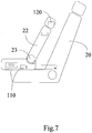
Fig 6 ~8 are schematic views showing the movement of the backrest due to the function of the angle adjuster of the preferred embodiment of the present invention; -
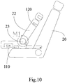
Figs. 9~11 are schematic views showing movement of the backrest due to the function of the angle adjuster of the preferred embodiment of the present invention in a different perspective; -
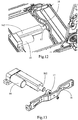
Fig. 12 is a partial perspective view showing the mounting of the pulling sensor of the preferred embodiment of the present invention; -
Fig. 13 is an exploded perspective view of the pulling sensor of the preferred embodiment of the present invention; -
Fig. 14 is a partial perspective view showing the mounting of the displacement sensor of the preferred embodiment of the present invention; and -
Fig. 15 is an exploded perspective view of the displacement sensor of the preferred embodiment of the present invention. - Embodiments, or examples, of the disclosure illustrated in the drawings are now described using specific language. It shall be understood that no limitation of the scope of the disclosure is hereby intended. Any alteration or modification of the described embodiments, and any further applications of principles described in this document, are to be considered as normally occurring to one of ordinary skill in the art to which the disclosure relates. Reference numerals may be repeated throughout the embodiments, but this does not necessarily mean that feature(s) of one embodiment apply to another embodiment, even if they share the same reference numeral. It shall be understood that, although the terms first, second, third, etc. may be used herein to describe various elements, components, regions, layers or sections, these elements, components, regions, layers or sections are not limited by these terms. Rather, these terms are merely used to distinguish one element, component, region, layer or section from another region, layer or section. Thus, a first element, component, region, layer or section discussed below could be termed a second element, component, region, layer or section without departing from the teachings of the present inventive concept. The terminology used herein is for the purpose of describing particular example embodiments only and is not intended to be limited to the present inventive concept. As used herein, the singular forms "a," "an" and "the" are intended to include the plural forms as well, unless the context clearly indicates otherwise. It shall be further understood that the terms "comprises" and "comprising," when used in this specification, point out the presence of stated features, integers, steps, operations, elements, or components, but do not preclude the presence or addition of one or more other features, integers, steps, operations, elements, components, or groups thereof.
- The following description describes different preferred embodiments of how the adjustment system and method thereof between a child car safety seat and a backrest so that the status gathering module on the child car safety seat is able to pick up the child status on a child car safety seat and environment situations inside the car as well as the child's vital characteristics and proceed analysis to remind of the driver or the parent(s) of how the child feels. When necessary, the information picked up is sent to the onboard computer to adjust the onboard environment.
- The following disclosure incorporated with the accompanying drawings discusses further about the preferred embodiment of the present invention.
- First of all, with reference to
Figs. 1∼3 , the adjustment system of the child car safety seat includes a controllingunit 13, a first driving unit14 and asecond driving unit 15 both of which are respectively connected to the controllingunit 13. - ISOFIX stands for international standards organization FIX and is an organization concerning standards for child car seat. ISOFIX focuses on fast and easy connection between the child car seat and the car aiming to reach the goal of any ISOFIX approved child car seat would be able to readily and fast connect to the car to enhance safety.
- According to the above goal, the adjustment system of the preferred embodiment of the present invention further includes an
installation frame 16 and anisofix connection 161 mounted on top of theinstallation frame 16. Theinstallation frame 16 is slidably mounted on aseat frame 21 via the assistance of apushrod 162 which may be a mechanical gear unit or a hydraulic cylinder. Theisofix connection 161 is securely connected to a corresponding onboard connection. - The
first driving unit 14 adopts isofix motor and is mounted to drive thepushrod 162 such that the movement of thepushrod 162 is able to drive theinstallation frame 16 along with theisofix connection 161 to move forward or backward in regard to theseat frame 21, as shown inFigs. 1 and3 . - With reference to
Figs. 4 and5 , thesecond driving unit 15 is provided to drive anangle adjuster 23 mounted at a joint between a backrest and a seat of the child car seat so that angle between the backrest and the seat is changeable. Theangle adjuster 23 has a first end securely mounted on thebackrest 22 and a second end provided with ahole 152 dimensioned and shaped to securely receive therein anaxle 231 extending out from thehole 152. In this embodiment, thehole 152 and theaxle 231 are both square in cross section. Thus, when theaxle 231 is driven to rotate, thebackrest 22 is able to change angle relative to theseat frame 21. - It is noted that the angle adjuster is mounted on the car safety seat to fulfill the angle adjustment of the backrest. The device normally is composed of a backrest connection plate, a seat connection plate, core elements, a handle or an adjusting handle and recoil springs. In some low-cost car safety seat, the backrest connection plate and the seat connection plate are integrated into the backrest frame and the seat frame. The angle adjustment may be divided into two categories, level adjustment and stepless adjustment.
- The controlling unit 13 (Electronic Control Unit, ECU) monitors signals from the isofix motor to have the first monitoring signal and signals from the angle adjuster to have the second monitoring signal.
- After receiving the first monitoring signal and the second monitoring signal, the controlling
unit 13 processes the received signals according predetermined protocol to generate operation commands. - The
first driving unit 14 is electrically connected to the controllingunit 13 to control the isofix device to operate according to the operation commands from the controllingunit 13. - The
second driving unit 15 is electrically connected to the controllingunit 13 to control thebackrest 22 to operate according to the operation commands from the controllingunit 13. - Further, the controlling
unit 13 of the system of the preferred embodiment of the present invention is composed of the following modules, which includes: - a
signal receiving module 131 for receiving the first monitoring signal associated with isofix device and the second monitoring signal associated with the backrest; - a
signal processing module 132 connected to thesignal receiving module 131 to process signal so as to generate operation commands; - a
signal output module 133 connected to thesignal processing module 132 to output operation commands generated by thesignal processing module 132; - an
information storage module 134 connected to thesignal processing module 132 for recording the first monitoring signal and the second monitoring signal respectively corresponding to the isofix device and the backrest when reaching a specific position; and - a
radio communication module 135 connected to theinformation storage module 134 for transmitting the first monitoring signal and the second monitoring signal recorded in theinformation storage module 134. - In which, the
radio communication module 135 is connected to the onboard computer (ECU) or cloud via internet such that theradio communication module 135 is able to transmit signals to wherever appropriate through WIFI, ZIGBEE, GPRS or others. - The controlling unit further has an alarm module (not shown). The alarm module is connected to the
signal processing module 132 to check if parameters contained in the first monitoring signal or the second monitoring signal exceed predetermined range and sends out warning message when exceeded. An alarm (honk or warning light or the like) may be mounted on the car safety seat to respond to the warning message and call for assistance from the experts. Alternatively, the alarm module is connected to the radio communication module such that the radio communication module is able to send out the warning message from the alarm module along with parameters recorded in the information storage module to the onboard computer or cloud. - The following embodiments present the fulfillment of the adjustment system of the present invention, which is installed in the car safety seat between the isofix seat and the backrest.
- The isofix motor is activated to drive the pushrod of the isofix motor to push the isofix device to any desired position. After the isofix motor is activated and an electrical current signal is thus generated and so as the first monitoring signal. The controlling unit (ECU) of the car safety seat activates the angle adjuster after receiving the first monitoring signal to drive the backrest. When the backrest of the car safety seat is closely next to the onboard backrest, the motor of the angle adjuster occurs locked-rotor current which is larger than working current of the angle adjuster motor. ECU may detect existence of the locked-rotor current to judge the location of the backrest of the car safety seat.
- Similarly, the angle adjuster motor is activated and the backrest of the car safety seat is consequently rotated relative to the seat of the car safety seat. In the meantime, the current from the angle adjuster motor generates the second monitoring signal which is sent out to the controlling unit. After the controlling unit (ECU) of the car safety seat receives the second monitoring signal, the isofix motor is activated to adjust the pushrod's extension length. When the backrest of the car safety seat is closely against the onboard backrest, the motor of the angle adjuster occurs locked-rotor current, which is larger than working current of the angle adjuster motor. ECU may detect existence of the locked-rotor current to determine whether the extension length of the pushrod reaches the required length.
- With reference to
Figs 6-11 , a pulling sensor is provided and is connected to the pushrod. The pullingsensor 110 mounted between the installation frame and the pushrod is to monitor pulling variations between the pushrod and the installation frame in real time so as to generate the first monitoring signal. - A
pressure sensor 120 is provided and mounted on the backrest of the car safety seat to monitor pressure changes from the backrest of the car safety seat to the onboard backrest to thus generate the second monitoring signal. - With reference to
Figs. 12 and 13 , the pullingsensor 17 is mounted between thepushrod 162 and theinstallation frame 16 and has studs integrally formed on two distal ends thereof to correspond to two threaded bores respectively defined in thepushrod 162 and theinstallation frame 16 so that the pulling sensor is able to be securely mounted between the pushrod and the installation frame. - With reference to
Figs. 6-8 , the pushrod is activated to place the installation frame at a random position, as shown inFigs. 6 and7 . Due to the movement of the installation frame, the pullingsensor 110 is activated and the first monitoring signal is thus generated. After the ECU receives the first monitoring signal, theangle adjuster 23 is then operated accordingly to adjust thebackrest 22 of the car safety seat to move toward theonboard backrest 20. When thebackrest 22 of the car safety seat is leaning closely against theonboard backrest 22, thepressure sensor 120 mounted on thebackrest 22 of the car safety seat senses the pressure change between thebackrest 22 of the car safety seat and theonboard backrest 20, the second monitoring signal is generated and transmitted. ECU receives the second monitoring signal from thepressure sensor 120 and verifies the actual position of thebackrest 22 of the car safety seat accordingly. After the position of the backrest of the car safety seat reaches the predetermined position, the ECU sends out a command to stop movement of theangle adjuster 23, as shown inFig. 8 , to complete adjustment of thebackrest 22 by the isofix device. - With reference to
Figs. 9-11 , the angle adjuster is activated, as shown inFigs. 9-10 . The movement of the angle adjuster triggers the transmission of the second monitoring signal from thepressure sensor 120. The controlling element (ECU) of the car safety seat receives the second monitoring signal and then activates the isofix motor to operate the pushrod of the isofix device. While the pushrod extends, thebackrest 22 gradually leans against theonboard backrest 20. Due to the engagement between the two backrests, the pullingsensor 110 detects the pulling force between the pushrod and the installation frame and then sends out the first monitoring signal. The ECU receives the first monitoring signal to judge, according to the raw data contained in the first monitoring signal, whether the pushrod reaches the predetermined length, and then sends out a command to stop operation of the pushrod should the data examined qualify previously determined criteria, as shown inFig. 11 . - In a preferred embodiment, it is also possible to connect the isofix motor to the ECU (the controlling element of the car safety seat) to use the current signal from the isofix motor to activate the ECU. The activation of the ECU automatically operates the movement of the angle adjuster to proceed angle adjustment to the backrest of the car safety seat. Similarly, it is possible to electrically connect the angle adjuster motor to the ECU so that the current signal from the angle adjuster motor activates the ECU. Consequently, the isofix motor is operated by the ECU to proceed the following adjustment. The pressure sensor may be mounted on the onboard backrest at a location where the backrest of the car safety seat definitely contacts with.
- With reference to
Figs 6-11 , a pulling sensor is provided and is connected to the pushrod. The pullingsensor 110 mounted between the installation frame and the pushrod is to monitor pulling variations between the pushrod and the installation frame in real time so as to generate the first monitoring signal. -
Apressure sensor 120 is provided and mounted on the backrest of the car safety seat to monitor pressure changes from the backrest of the car safety seat to the onboard backrest to thus generate the second monitoring signal. - With reference to
Figs. 12 and 13 , the pullingsensor 17 is mounted between thepushrod 162 and theinstallation frame 16 and has studs integrally formed on two distal ends thereof to correspond to two threaded bores respectively defined in thepushrod 162 and theinstallation frame 16 so that the pulling sensor is able to be securely mounted between the pushrod and the installation frame. - With reference to
Figs. 6-8 , the pushrod is activated to place the installation frame at a random position, as shown inFigs. 6 and7 . Due to the movement of the installation frame, the pullingsensor 110 is activated and the first monitoring signal is thus generated. After the ECU receives the first monitoring signal, theangle adjuster 23 is then operated accordingly to adjust thebackrest 22 of the car safety seat to move toward theonboard backrest 20. When thebackrest 22 of the car safety seat is leaning closely against theonboard backrest 22, thepressure sensor 120 mounted on thebackrest 22 of the car safety seat senses the pressure change between thebackrest 22 of the car safety seat and theonboard backrest 20, the second monitoring signal is generated and transmitted. ECU receives the second monitoring signal from thepressure sensor 120 and verifies the actual position of thebackrest 22 of the car safety seat accordingly. After the position of the backrest of the car safety seat reaches the predetermined position, the ECU sends out a command to stop movement of theangle adjuster 23, as shown inFig. 8 , to complete adjustment of thebackrest 22 by the isofix device. - With reference to
Figs. 9-11 , the angle adjuster is activated, as shown inFigs. 9-10 . The movement of the angle adjuster triggers the transmission of the second monitoring signal from thepressure sensor 120. The controlling element (ECU) of the car safety seat receives the second monitoring signal and then activates the isofix motor to operate the pushrod of the isofix device. While the pushrod extends, thebackrest 22 gradually leans against theonboard backrest 20. Due to the engagement between the two backrests, the pullingsensor 110 detects the pulling force between the pushrod and the installation frame and then sends out the first monitoring signal. The ECU receives the first monitoring signal to judge, according to the raw data contained in the first monitoring signal, whether the pushrod reaches the predetermined length, and then sends out a command to stop operation of the pushrod should the data examined qualify previously determined criteria, as shown inFig. 11 . - In a preferred embodiment, it is also possible to connect the isofix motor to the ECU (the controlling element of the car safety seat) to use the current signal from the isofix motor to activate the ECU. The activation of the ECU automatically operates the movement of the angle adjuster to proceed angle adjustment to the backrest of the car safety seat. Similarly, it is possible to electrically connect the angle adjuster motor to the ECU so that the current signal from the angle adjuster motor activates the ECU. Consequently, the isofix motor is operated by the ECU to proceed the following adjustment. The pressure sensor may be mounted on the onboard backrest at a location where the backrest of the car safety seat definitely contacts with.
- A
displacement sensor 18 is provided and located on thepushrod 162 of the isofix device. Thedisplacement sensor 18 has asensing rod 181 connected to theinstallation frame 16 to monitor displacement of the installation so as to generate a first monitoring signal. A pressure sensor is provided and mounted on the backrest of the car safety seat to monitor pressure change from the backrest of the car safety seat so as to generate a second monitoring signal. - With reference to
Figs. 14 and 15 , thedisplacement sensor 18 is mounted on thepushrod 162 via apositioning block 19. One distal end of thepushrod 162 is mounted on the seat frame and the other distal end of thepushrod 162 is telescopically connected to theinstallation frame 16. Thepositioning block 19, thepushrod 162 and thedisplacement sensor 18 are respectively interference fitted. Thesensing rod 181 of thedisplacement sensor 18 has a threaded end and theinstallation frame 16 has a threaded hole such that extension of the threaded end into the threaded hole of the installation frame secures the connection of thesensing rod 181 to theinstallation frame 16. - When the
pushrod 162 is pushes, theinstallation frame 16 is moved to a random position, which activates thedisplacement sensor 18 to generate the first monitoring signal. When the ECU receives the first monitoring signal, the ECU automatically activates the angle adjuster to move the backrest of the car safety seat toward the onboard backrest. After the backrest of the car safety seat gradually leans closely against the onboard backrest, the ECU may determine whether the backrest of the car safety seat reaches the predetermined position according to the data read from the pressure sensor. - The angle adjuster is activated and the isofix motor is activated by the ECU to adjust the extension length of the pushrod. When the backrest of the car safety seat is closely connected to the onboard backrest, the ECU may determine whether the pushrod reaches the previously determined position via the data from the displacement sensor sensing the displacement of the installation frame.
- In this embodiment, it is also possible to electrically connect the isofix motor to the controlling unit (ECU) of the car safety seat so that the current signal from the activation of the isofix motor triggers the ECU. The ECU activates the angle adjuster to proceed adjustment of the backrest of the car safety seat. Similarly, the angle adjuster may be electrically connected to the ECU such that the current signal from the activation of the angle adjuster motor triggers the ECU. The ECU activates the isofix device to proceed the adjustment. The pressure sensor in this embodiment may be mounted on the onboard backrest at a location where the backrest of the car safety seat is definitely in contact with.
- This application involves the car safety seat adjustment, especially to the related adjustments of the angle of the backrest or the extension of the isofix device of the car safety seat to ensure the close engagement between the backrest of the car safety seat and the onboard backrest. By way of reading the value from the angle adjuster to determine the position of the backrest of the car safety seat or the readings from the pressure sensor to determine whether the backrest of the car safety seat engages with the onboard backrest or not or from the information transmitted from the pulling sensor, the ECU then provide the best support to the child sitting on the car safety seat via positioning the backrest of the backrest of the car safety seat. The ECU analyzes the data and then transmits the data to onboard computer, cloud, mobile terminal of emergency response center to ensure that the child sitting on the car safety seat is well protected when encountering brake, sudden brake or accidents of any kind. The data received can be used to control the activation of the air-bags all around the car or the explosion range of the air bag on the car safety seat. In emergency situations, the data can also be used to control the position of the front seat or the back seat or even the car windows.
- The extension of the isofix device can be measured by electrical isofix. While adjusting the backrest of the car safety seat to any position via electrical isofix along with the angle adjuster, the backrest of the car safety seat or the angle adjuster can also be rigidly mounted on the onboard seat (the backrest of the car safety seat along with the isofix as well as the onboard car seat can be securely connected and the current signal from the motor of the isofix pushrod can be used to determine whether the connection is appropriate and the extension of the pushrod and the angle of the backrest of the car safety seat satisfies the predetermined criteria such that when encountering an impact, the deformation of the onboard car seat as well as the car safety seat is reduced and the child sitting on the car safety seat is protected.
- From the embodiment, it is appreciated that the adjustment system of the car safety seat is described in detail and the method to achieve the designed purpose comprises the steps of:
- S001:providing a car safety seat controlling unit for receiving a first monitoring signal from an isofix device or a second monitoring signal from a backrest and analyzing the received data to generate an operation command;
- S002: providing a first driving unit to drive the isofix device according to the operation command; or
- S003: providing a second driving unit to drive an angle adjuster mounted on a car safety seat to move a backrest of the car safety seat relative to the onboard backrest.
- It is appreciated that the structure, scale, size...etc. provided in the detailed description as well as in the accompanying drawings are all for explanatory purpose to allow people skilled in the art to read and understand the operation contained therein and do not intend to limit the embodiment(s) in any way. Any alternation, amendment or modification to the structure, scale or size to the embodiment shown above shall still fall within the protection scope sought and defined in the following claim set should any alternation, amendment or modification to the structure, scale or size to the preferred embodiment of the present invention not affect the function as well as the purpose set forth. Meanwhile, the "up", "down", "left", "right", "middle" and "a" are all used for explanatory purpose and do not intend to limit the embodiment(s) in any way. Any alternation, amendment or modification to the above shall still fall within the protection scope sought and defined in the following claim set.
Claims (10)
- An adjustment system for adjusting relative position between a car safety seat and an onboard backrest (20), said car safety seat includes a car safety seat isofix device and a backrest (22), wherein the adjustment system comprises:a controlling unit (13) for receiving a first monitoring signal in relation to the car safety seat isofix device or a second monitoring signal in relation to the backrest (22) of the car safety seat and analyzing the first monitoring signal or the second monitoring signal to consequently generate an operation command;a first driving unit (14) in connection to the controlling unit (13) to drive the car safety seat isofix device according to the operation command; ora second driving unit (15) in connection to the controlling unit (13) to drive the backrest to move according to the operation command.
- The adjustment system as claimed in claim 1, wherein the first driving unit (14) is an isofix motor to drive the car safety seat isofix device, the second driving unit (15) is an angle adjuster motor which is provided to drive an angle adjuster (23) mounted between the backrest (22) of the car safety seat device and a seat of the car safety seat to control movement of the backrest of the car safety seat.
- The adjustment system as claimed in claim 2, wherein the controlling unit (13) monitors a current signal from the isofix motor to have the first monitoring signal; and
the controlling unit monitors a current signal from the angle adjuster (23) to have the second monitoring signal. - The adjustment system as claimed in claim 2, wherein the car safety seat isofix device includes an installation frame (16) adapted to be connected to the car safety seat via a pushrod (162) such that the pushrod (162) is able to move the installation frame (16) to move along the car safety seat;
the first driving unit (14) adapted to be mounted on the car safety seat to move the pushrod (162). - The adjustment system as claimed in claim 4 further comprising a pulling sensor (110) mounted between the pushrod (162) and the installation frame (16) to monitor pull change between the pushrod (162) and the installation frame (16) so as to generate the first monitoring signal in response to the pull change;
a pressure sensor (120) mounted on the backrest (22) of the car safety seat to monitor pressure change on the backrest (22) so as to generate the second monitoring signal in response to the pressure change. - The adjustment system as claimed in claim 4 further comprising:a displacement sensor (18) mounted on the pushrod (162) and having a sensing rod (181) integrally formed with the displacement sensor (18) to securely connect to the installation frame (16) for monitoring displacement change of the installation frame (16) so as to generate the first monitoring signal in response to the displacement change;a pressure sensor (120) mounted on the backrest (22) of the car safety seat to monitor pressure change on the backrest (22) so as to generate the second monitoring signal in response to the pressure change.
- The adjustment system as claimed in claim 2, wherein one end of the angle adjuster motor is mounted on the backrest (22) of the car safety seat and the other end thereof is provided with a driving wheel which has a hole defined there through to securely receive therein extension of an axle integrally extended from the angle adjuster so that rotation of the driving wheel drives the angle adjuster (23) to move.
- The adjustment system as claimed in claim 1, wherein the controlling unit (13) comprises:a signal receiving module (131) for receiving the first monitoring signal associated with the car safety seat isofix device or the second monitoring signal associated with the backrest (22);a signal processing module (132) connected to the signal receiving module (131) to process signal so as to generate operation commands; anda signal output module (133) connected to the signal processing module (132) to output operation commands generated by the signal processing module (132).
- The adjustment system as claimed in claim 8, wherein the controlling unit (13) further has:an information storage module (134) connected to the signal processing module (132) for recording the first monitoring signal or the second monitoring signal respectively corresponding to the car safety seat isofix device or the backrest (22); anda radio communication module (135) connected to the information storage module for transmitting the first monitoring signal or the second monitoring signal recorded in the information storage module (134), the radio communication module (135) being connected to an onboard computer or cloud.
- A method for adjusting relative position between a car safety seat and an onboard backrest (20), wherein the method comprising the steps of:providing a car safety seat controlling unit (13) for receiving a first monitoring signal in relation to an isofix device of the car safety seat or a second monitoring signal in relation to a backrest (22) and analyzing the received data to generate an operation command;providing a first driving unit (14) to drive an isofix device of the car safety seat according to the operation command; orproviding a second driving unit (15) to drive an angle adjuster (23) mounted on the car safety seat according to the operation command to move a backrest (22) of the car safety seat relative to the onboard backrest (20).
Applications Claiming Priority (2)
| Application Number | Priority Date | Filing Date | Title |
|---|---|---|---|
| CN201710010890.8A CN106740310B (en) | 2017-01-06 | 2017-01-06 | System and method for interlocking adjustment of isofix and backrest of child safety seat |
| PCT/CN2017/079694 WO2018126549A1 (en) | 2017-01-06 | 2017-04-07 | System and method for linkage adjustment of isofix and backrest of child safety seat |
Publications (3)
| Publication Number | Publication Date |
|---|---|
| EP3444144A1 EP3444144A1 (en) | 2019-02-20 |
| EP3444144A4 EP3444144A4 (en) | 2020-01-15 |
| EP3444144B1 true EP3444144B1 (en) | 2021-03-31 |
Family
ID=58950071
Family Applications (1)
| Application Number | Title | Priority Date | Filing Date |
|---|---|---|---|
| EP17890005.6A Active EP3444144B1 (en) | 2017-01-06 | 2017-04-07 | System and method for linkage adjustment of isofix and backrest of child safety seat |
Country Status (5)
| Country | Link |
|---|---|
| US (1) | US10717376B2 (en) |
| EP (1) | EP3444144B1 (en) |
| CN (2) | CN106740310B (en) |
| ES (1) | ES2878328T3 (en) |
| WO (1) | WO2018126549A1 (en) |
Families Citing this family (15)
| Publication number | Priority date | Publication date | Assignee | Title |
|---|---|---|---|---|
| US10838396B2 (en) * | 2017-04-18 | 2020-11-17 | Cisco Technology, Inc. | Connecting robotic moving smart building furnishings |
| JP6944338B2 (en) * | 2017-10-20 | 2021-10-06 | 株式会社カーメイト | ISOFIX child seat |
| CN107791906A (en) * | 2017-10-24 | 2018-03-13 | 上海沃雨电子科技有限公司 | Child safety seat skeleton and its method for dismounting ISOFIX |
| CN108225429A (en) * | 2018-01-16 | 2018-06-29 | 黑子信息科技(广东)有限公司 | comfort monitoring method and device |
| CN108725275B (en) * | 2018-05-29 | 2024-04-05 | 上海沃雨电子科技有限公司 | Child safety seat and ISOFIX bidirectional adjusting structure thereof |
| CN109435796A (en) * | 2018-12-18 | 2019-03-08 | 麦克英孚(宁波)婴童用品有限公司 | A kind of automobile child seat quick-mount system and method for rapidly mounting |
| CN111516563B (en) * | 2019-02-01 | 2022-11-04 | 宝钜瑞士股份有限公司 | Child safety seat and its linkage |
| CN110406446B (en) * | 2019-08-14 | 2024-02-06 | 安道拓(重庆)汽车部件有限公司 | Automobile seat with self-adaptive side wings |
| CN113022393A (en) * | 2019-12-25 | 2021-06-25 | 深圳市大富科技股份有限公司 | Child safety seat and automobile |
| CN113119817B (en) * | 2020-01-16 | 2022-07-29 | 长城汽车股份有限公司 | Integrated child seat and automobile seat |
| CN113581029B (en) * | 2021-08-31 | 2023-01-06 | 重庆长安汽车股份有限公司 | Seat frame structure with memory function seat |
| CN113799671B (en) * | 2021-10-29 | 2023-04-07 | 延锋国际座椅系统有限公司 | Control method for electrically adjusting automobile seat armrest |
| CN114486230B (en) * | 2022-04-02 | 2022-07-01 | 常州市金甲虫精密机械科技有限公司 | Torque detection device for automobile seat angle adjuster |
| CN116394809B (en) * | 2023-03-02 | 2025-08-05 | 好孩子儿童用品有限公司 | Child safety seat |
| CN117338320B (en) * | 2023-09-08 | 2024-10-29 | 南方医科大学顺德医院(佛山市顺德区第一人民医院) | Neonatal radiation protection equipment and control method thereof |
Family Cites Families (28)
| Publication number | Priority date | Publication date | Assignee | Title |
|---|---|---|---|---|
| US3404917A (en) * | 1966-06-28 | 1968-10-08 | Reynolds Res & Mfg Corp | Mounting bracket for automobile baby seat |
| IT213923Z2 (en) * | 1988-03-07 | 1990-03-01 | Como | ADJUSTABLE INCLINATION SEAT FOR THE TRANSPORT OF CHILDREN ON CARS. |
| US5524964A (en) * | 1994-11-21 | 1996-06-11 | U.S. Magnet Corporation | Child restraint car seat and bed |
| DE29620067U1 (en) * | 1996-11-12 | 1997-02-13 | Kiddy GmbH Auto-Kindersitze, 07356 Thimmendorf | Child safety seat |
| JP4211182B2 (en) * | 2000-02-15 | 2009-01-21 | トヨタ自動車株式会社 | Child seat device for vehicle |
| WO2004089685A1 (en) * | 2003-04-14 | 2004-10-21 | Nissan Technical Centre Europe Ltd. | Vehicle seat assembly |
| PT1477358E (en) * | 2003-05-14 | 2007-12-03 | Jane Sa | An infant seat with armrest for motorcars |
| EP2008257A2 (en) * | 2006-03-30 | 2008-12-31 | Asher S. Saban | Protecting children and passengers with respect to a vehicle |
| DE102007022463A1 (en) * | 2007-05-09 | 2008-11-13 | Takata-Petri Ag | measuring system |
| WO2010025571A1 (en) * | 2008-09-05 | 2010-03-11 | Magna Marque International Inc. | Adjuster and hinge for child booster seat |
| JP5441444B2 (en) * | 2009-03-02 | 2014-03-12 | 株式会社カーメイト | Child seat for vehicle |
| DE102011076702A1 (en) * | 2011-05-30 | 2012-12-06 | TAKATA Aktiengesellschaft | Child seat for a motor vehicle |
| US9751433B2 (en) * | 2011-10-06 | 2017-09-05 | Thorley Industries Llc | Child restraint system with user interface |
| IL220323A (en) * | 2012-06-12 | 2015-03-31 | Celine Herut | Vehicular seat |
| CN202863196U (en) * | 2012-10-08 | 2013-04-10 | 好孩子儿童用品有限公司 | Locking device of kid car safety seat |
| CN203449975U (en) * | 2013-06-26 | 2014-02-26 | 江苏百佳斯特汽车制品有限公司 | Safety seat |
| CN203698014U (en) * | 2014-01-02 | 2014-07-09 | 宁波妈咪宝婴童用品制造有限公司 | Unlocking mechanism for backrest of child safety seat |
| CN204340758U (en) * | 2014-11-25 | 2015-05-20 | 苍安国 | A kind of automobile children safety chair |
| CN204870626U (en) * | 2015-05-26 | 2015-12-16 | 上海童璨婴童用品有限公司 | 0 -1 -2 -3 group takes children's safety seat of ISOFIX interface |
| EP3112209B1 (en) * | 2015-07-03 | 2017-05-17 | Przemyslowy Instytut Motoryzacji | Child safety seat with a device for pretensioning integrated safety belts restraining a child in the seat |
| CN204978314U (en) * | 2015-08-12 | 2016-01-20 | 上海初德电气有限公司 | Car seat's ISOFIX electric telescopic device |
| CN205059330U (en) * | 2015-10-29 | 2016-03-02 | 上海童璨婴童用品有限公司 | 0 -1 -2 -3 group takes safe seat of ISOFIX interface |
| WO2017077014A1 (en) * | 2015-11-06 | 2017-05-11 | Iee International Electronics & Engineering S.A. | Optimized electrode shape for capacitive occupant classification system |
| CN107284311B (en) * | 2016-03-30 | 2020-06-23 | 上海沃雨电子科技有限公司 | Folding electric child safety seat |
| CN107264348B (en) * | 2016-04-07 | 2020-03-31 | 上海沃雨电子科技有限公司 | Folding manual child safety seat |
| CN205523805U (en) * | 2016-05-03 | 2016-08-31 | 崔巍 | Safe seat with ISOfix connects |
| CN105946638A (en) * | 2016-05-25 | 2016-09-21 | 清华大学苏州汽车研究院(相城) | ISOFIX regulating device for child safety seat and child safety seat |
| CN206598749U (en) * | 2017-01-06 | 2017-10-31 | 上海沃雨电子科技有限公司 | The system that child safety seat isofix is adjusted with back-rest linked |
-
2017
- 2017-01-06 CN CN201710010890.8A patent/CN106740310B/en active Active
- 2017-01-06 CN CN201811025985.8A patent/CN109130977B/en active Active
- 2017-04-07 WO PCT/CN2017/079694 patent/WO2018126549A1/en not_active Ceased
- 2017-04-07 US US16/301,239 patent/US10717376B2/en active Active
- 2017-04-07 EP EP17890005.6A patent/EP3444144B1/en active Active
- 2017-04-07 ES ES17890005T patent/ES2878328T3/en active Active
Non-Patent Citations (1)
| Title |
|---|
| None * |
Also Published As
| Publication number | Publication date |
|---|---|
| CN106740310B (en) | 2019-06-28 |
| CN109130977A (en) | 2019-01-04 |
| EP3444144A4 (en) | 2020-01-15 |
| WO2018126549A1 (en) | 2018-07-12 |
| ES2878328T3 (en) | 2021-11-18 |
| US20190160980A1 (en) | 2019-05-30 |
| CN109130977B (en) | 2020-12-01 |
| CN106740310A (en) | 2017-05-31 |
| EP3444144A1 (en) | 2019-02-20 |
| US10717376B2 (en) | 2020-07-21 |
Similar Documents
| Publication | Publication Date | Title |
|---|---|---|
| US10717376B2 (en) | Adjustment system and method thereof between a child car safety seat and a backrest | |
| US6758495B2 (en) | Method and safety restraint device for restraining an occupant on a vehicle seat | |
| CN103619677B (en) | Motor vehicle with driver assistance unit | |
| EP2138345B1 (en) | Power seat drive device | |
| KR20090083910A (en) | Driver assistance system with driver presence monitoring | |
| US8024089B2 (en) | Device for a child seat | |
| CN1692028A (en) | Device for adjusting at least one vehicle seat | |
| WO2022072656A1 (en) | Force sensing seat belt sensor assembly | |
| EP1712427A4 (en) | Occupant restraint apparatus and occupant restraint system | |
| CN108032856A (en) | It is a kind of to lead passively integrated multistage belt with pre-load device control system and its method | |
| KR101361661B1 (en) | Integrated intelligent safe system for vehicles | |
| KR20200136000A (en) | Hazardous activity detection system while driving based on the position control of both hands holding the steering wheel | |
| US11091120B2 (en) | Vehicle seatbelt arrangement | |
| CN115649100A (en) | Airbag control method based on multi-source data and vehicle controller | |
| CN103358947A (en) | Vehicle | |
| CN206598749U (en) | The system that child safety seat isofix is adjusted with back-rest linked | |
| CN110562189A (en) | An active pretensioning seat belt system for a hydrogen vehicle | |
| EP2839997B1 (en) | Arrangement for control of vehicle seat belt alert arrangement, a seat, a vehicle, a method and use of the arrangement | |
| US20230052692A1 (en) | Method for a safety belt system, safety belt system for a vehicle, and vehicle with a safety belt system | |
| JP2005193898A (en) | System and method for adjustment of steering wheel | |
| CN214874695U (en) | Active protection device for child restraint system based on AEB system | |
| JP2008504168A (en) | Automotive safety devices | |
| CN100376430C (en) | Device for controlling a retracting mechanism | |
| US20060187067A1 (en) | Instantaneous sleep activated alarm | |
| CN121154404A (en) | Massage control method and massage control equipment for actively pre-judging collision |
Legal Events
| Date | Code | Title | Description |
|---|---|---|---|
| STAA | Information on the status of an ep patent application or granted ep patent |
Free format text: STATUS: THE INTERNATIONAL PUBLICATION HAS BEEN MADE |
|
| PUAI | Public reference made under article 153(3) epc to a published international application that has entered the european phase |
Free format text: ORIGINAL CODE: 0009012 |
|
| STAA | Information on the status of an ep patent application or granted ep patent |
Free format text: STATUS: REQUEST FOR EXAMINATION WAS MADE |
|
| 17P | Request for examination filed |
Effective date: 20181115 |
|
| AK | Designated contracting states |
Kind code of ref document: A1 Designated state(s): AL AT BE BG CH CY CZ DE DK EE ES FI FR GB GR HR HU IE IS IT LI LT LU LV MC MK MT NL NO PL PT RO RS SE SI SK SM TR |
|
| AX | Request for extension of the european patent |
Extension state: BA ME |
|
| A4 | Supplementary search report drawn up and despatched |
Effective date: 20191216 |
|
| RIC1 | Information provided on ipc code assigned before grant |
Ipc: B60N 2/26 20060101ALI20191210BHEP Ipc: B60N 2/02 20060101ALI20191210BHEP Ipc: B60N 2/28 20060101AFI20191210BHEP |
|
| DAV | Request for validation of the european patent (deleted) | ||
| DAX | Request for extension of the european patent (deleted) | ||
| RIC1 | Information provided on ipc code assigned before grant |
Ipc: B60N 2/26 20060101ALI20200424BHEP Ipc: B60N 2/02 20060101ALI20200424BHEP Ipc: B60N 2/28 20060101AFI20200424BHEP |
|
| STAA | Information on the status of an ep patent application or granted ep patent |
Free format text: STATUS: EXAMINATION IS IN PROGRESS |
|
| 17Q | First examination report despatched |
Effective date: 20200730 |
|
| REG | Reference to a national code |
Ref country code: DE Ref legal event code: R079 Ref document number: 602017035950 Country of ref document: DE Free format text: PREVIOUS MAIN CLASS: B60N0002280000 Ipc: B60N0002010000 |
|
| GRAP | Despatch of communication of intention to grant a patent |
Free format text: ORIGINAL CODE: EPIDOSNIGR1 |
|
| STAA | Information on the status of an ep patent application or granted ep patent |
Free format text: STATUS: GRANT OF PATENT IS INTENDED |
|
| RIC1 | Information provided on ipc code assigned before grant |
Ipc: B60N 2/01 20060101AFI20201215BHEP Ipc: B60N 2/02 20060101ALI20201215BHEP Ipc: B60N 2/28 20060101ALI20201215BHEP |
|
| INTG | Intention to grant announced |
Effective date: 20210120 |
|
| GRAS | Grant fee paid |
Free format text: ORIGINAL CODE: EPIDOSNIGR3 |
|
| GRAA | (expected) grant |
Free format text: ORIGINAL CODE: 0009210 |
|
| STAA | Information on the status of an ep patent application or granted ep patent |
Free format text: STATUS: THE PATENT HAS BEEN GRANTED |
|
| AK | Designated contracting states |
Kind code of ref document: B1 Designated state(s): AL AT BE BG CH CY CZ DE DK EE ES FI FR GB GR HR HU IE IS IT LI LT LU LV MC MK MT NL NO PL PT RO RS SE SI SK SM TR |
|
| REG | Reference to a national code |
Ref country code: GB Ref legal event code: FG4D Ref country code: CH Ref legal event code: EP |
|
| REG | Reference to a national code |
Ref country code: AT Ref legal event code: REF Ref document number: 1376566 Country of ref document: AT Kind code of ref document: T Effective date: 20210415 |
|
| REG | Reference to a national code |
Ref country code: DE Ref legal event code: R096 Ref document number: 602017035950 Country of ref document: DE |
|
| REG | Reference to a national code |
Ref country code: IE Ref legal event code: FG4D |
|
| REG | Reference to a national code |
Ref country code: LT Ref legal event code: MG9D |
|
| PG25 | Lapsed in a contracting state [announced via postgrant information from national office to epo] |
Ref country code: HR Free format text: LAPSE BECAUSE OF FAILURE TO SUBMIT A TRANSLATION OF THE DESCRIPTION OR TO PAY THE FEE WITHIN THE PRESCRIBED TIME-LIMIT Effective date: 20210331 Ref country code: FI Free format text: LAPSE BECAUSE OF FAILURE TO SUBMIT A TRANSLATION OF THE DESCRIPTION OR TO PAY THE FEE WITHIN THE PRESCRIBED TIME-LIMIT Effective date: 20210331 Ref country code: NO Free format text: LAPSE BECAUSE OF FAILURE TO SUBMIT A TRANSLATION OF THE DESCRIPTION OR TO PAY THE FEE WITHIN THE PRESCRIBED TIME-LIMIT Effective date: 20210630 Ref country code: BG Free format text: LAPSE BECAUSE OF FAILURE TO SUBMIT A TRANSLATION OF THE DESCRIPTION OR TO PAY THE FEE WITHIN THE PRESCRIBED TIME-LIMIT Effective date: 20210630 |
|
| PG25 | Lapsed in a contracting state [announced via postgrant information from national office to epo] |
Ref country code: RS Free format text: LAPSE BECAUSE OF FAILURE TO SUBMIT A TRANSLATION OF THE DESCRIPTION OR TO PAY THE FEE WITHIN THE PRESCRIBED TIME-LIMIT Effective date: 20210331 Ref country code: LV Free format text: LAPSE BECAUSE OF FAILURE TO SUBMIT A TRANSLATION OF THE DESCRIPTION OR TO PAY THE FEE WITHIN THE PRESCRIBED TIME-LIMIT Effective date: 20210331 Ref country code: SE Free format text: LAPSE BECAUSE OF FAILURE TO SUBMIT A TRANSLATION OF THE DESCRIPTION OR TO PAY THE FEE WITHIN THE PRESCRIBED TIME-LIMIT Effective date: 20210331 |
|
| REG | Reference to a national code |
Ref country code: NL Ref legal event code: MP Effective date: 20210331 |
|
| REG | Reference to a national code |
Ref country code: AT Ref legal event code: MK05 Ref document number: 1376566 Country of ref document: AT Kind code of ref document: T Effective date: 20210331 |
|
| PG25 | Lapsed in a contracting state [announced via postgrant information from national office to epo] |
Ref country code: AT Free format text: LAPSE BECAUSE OF FAILURE TO SUBMIT A TRANSLATION OF THE DESCRIPTION OR TO PAY THE FEE WITHIN THE PRESCRIBED TIME-LIMIT Effective date: 20210331 Ref country code: SM Free format text: LAPSE BECAUSE OF FAILURE TO SUBMIT A TRANSLATION OF THE DESCRIPTION OR TO PAY THE FEE WITHIN THE PRESCRIBED TIME-LIMIT Effective date: 20210331 Ref country code: NL Free format text: LAPSE BECAUSE OF FAILURE TO SUBMIT A TRANSLATION OF THE DESCRIPTION OR TO PAY THE FEE WITHIN THE PRESCRIBED TIME-LIMIT Effective date: 20210331 Ref country code: EE Free format text: LAPSE BECAUSE OF FAILURE TO SUBMIT A TRANSLATION OF THE DESCRIPTION OR TO PAY THE FEE WITHIN THE PRESCRIBED TIME-LIMIT Effective date: 20210331 Ref country code: CZ Free format text: LAPSE BECAUSE OF FAILURE TO SUBMIT A TRANSLATION OF THE DESCRIPTION OR TO PAY THE FEE WITHIN THE PRESCRIBED TIME-LIMIT Effective date: 20210331 Ref country code: LT Free format text: LAPSE BECAUSE OF FAILURE TO SUBMIT A TRANSLATION OF THE DESCRIPTION OR TO PAY THE FEE WITHIN THE PRESCRIBED TIME-LIMIT Effective date: 20210331 |
|
| REG | Reference to a national code |
Ref country code: ES Ref legal event code: FG2A Ref document number: 2878328 Country of ref document: ES Kind code of ref document: T3 Effective date: 20211118 |
|
| PG25 | Lapsed in a contracting state [announced via postgrant information from national office to epo] |
Ref country code: PL Free format text: LAPSE BECAUSE OF FAILURE TO SUBMIT A TRANSLATION OF THE DESCRIPTION OR TO PAY THE FEE WITHIN THE PRESCRIBED TIME-LIMIT Effective date: 20210331 Ref country code: PT Free format text: LAPSE BECAUSE OF FAILURE TO SUBMIT A TRANSLATION OF THE DESCRIPTION OR TO PAY THE FEE WITHIN THE PRESCRIBED TIME-LIMIT Effective date: 20210802 Ref country code: RO Free format text: LAPSE BECAUSE OF FAILURE TO SUBMIT A TRANSLATION OF THE DESCRIPTION OR TO PAY THE FEE WITHIN THE PRESCRIBED TIME-LIMIT Effective date: 20210331 Ref country code: SK Free format text: LAPSE BECAUSE OF FAILURE TO SUBMIT A TRANSLATION OF THE DESCRIPTION OR TO PAY THE FEE WITHIN THE PRESCRIBED TIME-LIMIT Effective date: 20210331 Ref country code: IS Free format text: LAPSE BECAUSE OF FAILURE TO SUBMIT A TRANSLATION OF THE DESCRIPTION OR TO PAY THE FEE WITHIN THE PRESCRIBED TIME-LIMIT Effective date: 20210731 |
|
| PG25 | Lapsed in a contracting state [announced via postgrant information from national office to epo] |
Ref country code: LU Free format text: LAPSE BECAUSE OF NON-PAYMENT OF DUE FEES Effective date: 20210407 |
|
| REG | Reference to a national code |
Ref country code: DE Ref legal event code: R097 Ref document number: 602017035950 Country of ref document: DE |
|
| PG25 | Lapsed in a contracting state [announced via postgrant information from national office to epo] |
Ref country code: DK Free format text: LAPSE BECAUSE OF FAILURE TO SUBMIT A TRANSLATION OF THE DESCRIPTION OR TO PAY THE FEE WITHIN THE PRESCRIBED TIME-LIMIT Effective date: 20210331 Ref country code: CH Free format text: LAPSE BECAUSE OF NON-PAYMENT OF DUE FEES Effective date: 20210430 Ref country code: AL Free format text: LAPSE BECAUSE OF FAILURE TO SUBMIT A TRANSLATION OF THE DESCRIPTION OR TO PAY THE FEE WITHIN THE PRESCRIBED TIME-LIMIT Effective date: 20210331 Ref country code: LI Free format text: LAPSE BECAUSE OF NON-PAYMENT OF DUE FEES Effective date: 20210430 Ref country code: MC Free format text: LAPSE BECAUSE OF FAILURE TO SUBMIT A TRANSLATION OF THE DESCRIPTION OR TO PAY THE FEE WITHIN THE PRESCRIBED TIME-LIMIT Effective date: 20210331 |
|
| PLBE | No opposition filed within time limit |
Free format text: ORIGINAL CODE: 0009261 |
|
| STAA | Information on the status of an ep patent application or granted ep patent |
Free format text: STATUS: NO OPPOSITION FILED WITHIN TIME LIMIT |
|
| 26N | No opposition filed |
Effective date: 20220104 |
|
| PG25 | Lapsed in a contracting state [announced via postgrant information from national office to epo] |
Ref country code: IE Free format text: LAPSE BECAUSE OF NON-PAYMENT OF DUE FEES Effective date: 20210407 |
|
| PG25 | Lapsed in a contracting state [announced via postgrant information from national office to epo] |
Ref country code: IS Free format text: LAPSE BECAUSE OF FAILURE TO SUBMIT A TRANSLATION OF THE DESCRIPTION OR TO PAY THE FEE WITHIN THE PRESCRIBED TIME-LIMIT Effective date: 20210731 |
|
| PG25 | Lapsed in a contracting state [announced via postgrant information from national office to epo] |
Ref country code: IT Free format text: LAPSE BECAUSE OF NON-PAYMENT OF DUE FEES Effective date: 20220407 |
|
| PG25 | Lapsed in a contracting state [announced via postgrant information from national office to epo] |
Ref country code: CY Free format text: LAPSE BECAUSE OF FAILURE TO SUBMIT A TRANSLATION OF THE DESCRIPTION OR TO PAY THE FEE WITHIN THE PRESCRIBED TIME-LIMIT Effective date: 20210331 |
|
| PG25 | Lapsed in a contracting state [announced via postgrant information from national office to epo] |
Ref country code: HU Free format text: LAPSE BECAUSE OF FAILURE TO SUBMIT A TRANSLATION OF THE DESCRIPTION OR TO PAY THE FEE WITHIN THE PRESCRIBED TIME-LIMIT; INVALID AB INITIO Effective date: 20170407 Ref country code: GR Free format text: LAPSE BECAUSE OF FAILURE TO SUBMIT A TRANSLATION OF THE DESCRIPTION OR TO PAY THE FEE WITHIN THE PRESCRIBED TIME-LIMIT Effective date: 20210331 |
|
| PGFP | Annual fee paid to national office [announced via postgrant information from national office to epo] |
Ref country code: IT Payment date: 20230411 Year of fee payment: 7 Ref country code: FR Payment date: 20230425 Year of fee payment: 7 Ref country code: ES Payment date: 20230504 Year of fee payment: 7 |
|
| PGFP | Annual fee paid to national office [announced via postgrant information from national office to epo] |
Ref country code: BE Payment date: 20230424 Year of fee payment: 7 |
|
| PGFP | Annual fee paid to national office [announced via postgrant information from national office to epo] |
Ref country code: GB Payment date: 20230424 Year of fee payment: 7 |
|
| PG25 | Lapsed in a contracting state [announced via postgrant information from national office to epo] |
Ref country code: MK Free format text: LAPSE BECAUSE OF FAILURE TO SUBMIT A TRANSLATION OF THE DESCRIPTION OR TO PAY THE FEE WITHIN THE PRESCRIBED TIME-LIMIT Effective date: 20210331 |
|
| PG25 | Lapsed in a contracting state [announced via postgrant information from national office to epo] |
Ref country code: TR Free format text: LAPSE BECAUSE OF FAILURE TO SUBMIT A TRANSLATION OF THE DESCRIPTION OR TO PAY THE FEE WITHIN THE PRESCRIBED TIME-LIMIT Effective date: 20210331 |
|
| PG25 | Lapsed in a contracting state [announced via postgrant information from national office to epo] |
Ref country code: MT Free format text: LAPSE BECAUSE OF FAILURE TO SUBMIT A TRANSLATION OF THE DESCRIPTION OR TO PAY THE FEE WITHIN THE PRESCRIBED TIME-LIMIT Effective date: 20210331 |
|
| GBPC | Gb: european patent ceased through non-payment of renewal fee |
Effective date: 20240407 |
|
| REG | Reference to a national code |
Ref country code: BE Ref legal event code: MM Effective date: 20240430 |
|
| PG25 | Lapsed in a contracting state [announced via postgrant information from national office to epo] |
Ref country code: BE Free format text: LAPSE BECAUSE OF NON-PAYMENT OF DUE FEES Effective date: 20240430 |
|
| PG25 | Lapsed in a contracting state [announced via postgrant information from national office to epo] |
Ref country code: GB Free format text: LAPSE BECAUSE OF NON-PAYMENT OF DUE FEES Effective date: 20240407 |
|
| PG25 | Lapsed in a contracting state [announced via postgrant information from national office to epo] |
Ref country code: FR Free format text: LAPSE BECAUSE OF NON-PAYMENT OF DUE FEES Effective date: 20240430 |
|
| PG25 | Lapsed in a contracting state [announced via postgrant information from national office to epo] |
Ref country code: GB Free format text: LAPSE BECAUSE OF NON-PAYMENT OF DUE FEES Effective date: 20240407 Ref country code: FR Free format text: LAPSE BECAUSE OF NON-PAYMENT OF DUE FEES Effective date: 20240430 Ref country code: BE Free format text: LAPSE BECAUSE OF NON-PAYMENT OF DUE FEES Effective date: 20240430 |
|
| REG | Reference to a national code |
Ref country code: ES Ref legal event code: FD2A Effective date: 20250528 |
|
| PGFP | Annual fee paid to national office [announced via postgrant information from national office to epo] |
Ref country code: DE Payment date: 20250411 Year of fee payment: 9 |
|
| PG25 | Lapsed in a contracting state [announced via postgrant information from national office to epo] |
Ref country code: ES Free format text: LAPSE BECAUSE OF NON-PAYMENT OF DUE FEES Effective date: 20240408 |