EP3444141B1 - Method and apparatus for safety control of electric moving vehicle - Google Patents
Method and apparatus for safety control of electric moving vehicle Download PDFInfo
- Publication number
- EP3444141B1 EP3444141B1 EP18188649.0A EP18188649A EP3444141B1 EP 3444141 B1 EP3444141 B1 EP 3444141B1 EP 18188649 A EP18188649 A EP 18188649A EP 3444141 B1 EP3444141 B1 EP 3444141B1
- Authority
- EP
- European Patent Office
- Prior art keywords
- electric motor
- moving vehicle
- electric
- force
- safety control
- Prior art date
- Legal status (The legal status is an assumption and is not a legal conclusion. Google has not performed a legal analysis and makes no representation as to the accuracy of the status listed.)
- Active
Links
Images





Classifications
-
- B—PERFORMING OPERATIONS; TRANSPORTING
- B60—VEHICLES IN GENERAL
- B60L—PROPULSION OF ELECTRICALLY-PROPELLED VEHICLES; SUPPLYING ELECTRIC POWER FOR AUXILIARY EQUIPMENT OF ELECTRICALLY-PROPELLED VEHICLES; ELECTRODYNAMIC BRAKE SYSTEMS FOR VEHICLES IN GENERAL; MAGNETIC SUSPENSION OR LEVITATION FOR VEHICLES; MONITORING OPERATING VARIABLES OF ELECTRICALLY-PROPELLED VEHICLES; ELECTRIC SAFETY DEVICES FOR ELECTRICALLY-PROPELLED VEHICLES
- B60L3/00—Electric devices on electrically-propelled vehicles for safety purposes; Monitoring operating variables, e.g. speed, deceleration or energy consumption
- B60L3/0007—Measures or means for preventing or attenuating collisions
- B60L3/0015—Prevention of collisions
-
- B—PERFORMING OPERATIONS; TRANSPORTING
- B60—VEHICLES IN GENERAL
- B60L—PROPULSION OF ELECTRICALLY-PROPELLED VEHICLES; SUPPLYING ELECTRIC POWER FOR AUXILIARY EQUIPMENT OF ELECTRICALLY-PROPELLED VEHICLES; ELECTRODYNAMIC BRAKE SYSTEMS FOR VEHICLES IN GENERAL; MAGNETIC SUSPENSION OR LEVITATION FOR VEHICLES; MONITORING OPERATING VARIABLES OF ELECTRICALLY-PROPELLED VEHICLES; ELECTRIC SAFETY DEVICES FOR ELECTRICALLY-PROPELLED VEHICLES
- B60L15/00—Methods, circuits, or devices for controlling the traction-motor speed of electrically-propelled vehicles
- B60L15/20—Methods, circuits, or devices for controlling the traction-motor speed of electrically-propelled vehicles for control of the vehicle or its driving motor to achieve a desired performance, e.g. speed, torque, programmed variation of speed
- B60L15/2009—Methods, circuits, or devices for controlling the traction-motor speed of electrically-propelled vehicles for control of the vehicle or its driving motor to achieve a desired performance, e.g. speed, torque, programmed variation of speed for braking
-
- B—PERFORMING OPERATIONS; TRANSPORTING
- B62—LAND VEHICLES FOR TRAVELLING OTHERWISE THAN ON RAILS
- B62B—HAND-PROPELLED VEHICLES, e.g. HAND CARTS OR PERAMBULATORS; SLEDGES
- B62B5/00—Accessories or details specially adapted for hand carts
- B62B5/0026—Propulsion aids
- B62B5/0069—Control
-
- B—PERFORMING OPERATIONS; TRANSPORTING
- B60—VEHICLES IN GENERAL
- B60L—PROPULSION OF ELECTRICALLY-PROPELLED VEHICLES; SUPPLYING ELECTRIC POWER FOR AUXILIARY EQUIPMENT OF ELECTRICALLY-PROPELLED VEHICLES; ELECTRODYNAMIC BRAKE SYSTEMS FOR VEHICLES IN GENERAL; MAGNETIC SUSPENSION OR LEVITATION FOR VEHICLES; MONITORING OPERATING VARIABLES OF ELECTRICALLY-PROPELLED VEHICLES; ELECTRIC SAFETY DEVICES FOR ELECTRICALLY-PROPELLED VEHICLES
- B60L15/00—Methods, circuits, or devices for controlling the traction-motor speed of electrically-propelled vehicles
- B60L15/20—Methods, circuits, or devices for controlling the traction-motor speed of electrically-propelled vehicles for control of the vehicle or its driving motor to achieve a desired performance, e.g. speed, torque, programmed variation of speed
- B60L15/2009—Methods, circuits, or devices for controlling the traction-motor speed of electrically-propelled vehicles for control of the vehicle or its driving motor to achieve a desired performance, e.g. speed, torque, programmed variation of speed for braking
- B60L15/2018—Methods, circuits, or devices for controlling the traction-motor speed of electrically-propelled vehicles for control of the vehicle or its driving motor to achieve a desired performance, e.g. speed, torque, programmed variation of speed for braking for braking on a slope
-
- B—PERFORMING OPERATIONS; TRANSPORTING
- B62—LAND VEHICLES FOR TRAVELLING OTHERWISE THAN ON RAILS
- B62B—HAND-PROPELLED VEHICLES, e.g. HAND CARTS OR PERAMBULATORS; SLEDGES
- B62B3/00—Hand carts having more than one axis carrying transport wheels; Steering devices therefor; Equipment therefor
- B62B3/001—Steering devices
-
- B—PERFORMING OPERATIONS; TRANSPORTING
- B62—LAND VEHICLES FOR TRAVELLING OTHERWISE THAN ON RAILS
- B62B—HAND-PROPELLED VEHICLES, e.g. HAND CARTS OR PERAMBULATORS; SLEDGES
- B62B5/00—Accessories or details specially adapted for hand carts
- B62B5/0026—Propulsion aids
- B62B5/0033—Electric motors
- B62B5/0036—Arrangements of motors
-
- B—PERFORMING OPERATIONS; TRANSPORTING
- B62—LAND VEHICLES FOR TRAVELLING OTHERWISE THAN ON RAILS
- B62B—HAND-PROPELLED VEHICLES, e.g. HAND CARTS OR PERAMBULATORS; SLEDGES
- B62B5/00—Accessories or details specially adapted for hand carts
- B62B5/0026—Propulsion aids
- B62B5/0069—Control
- B62B5/0073—Measuring a force
-
- B—PERFORMING OPERATIONS; TRANSPORTING
- B62—LAND VEHICLES FOR TRAVELLING OTHERWISE THAN ON RAILS
- B62B—HAND-PROPELLED VEHICLES, e.g. HAND CARTS OR PERAMBULATORS; SLEDGES
- B62B5/00—Accessories or details specially adapted for hand carts
- B62B5/04—Braking mechanisms; Locking devices against movement
-
- B—PERFORMING OPERATIONS; TRANSPORTING
- B62—LAND VEHICLES FOR TRAVELLING OTHERWISE THAN ON RAILS
- B62B—HAND-PROPELLED VEHICLES, e.g. HAND CARTS OR PERAMBULATORS; SLEDGES
- B62B5/00—Accessories or details specially adapted for hand carts
- B62B5/04—Braking mechanisms; Locking devices against movement
- B62B5/0404—Braking mechanisms; Locking devices against movement automatic
-
- B—PERFORMING OPERATIONS; TRANSPORTING
- B62—LAND VEHICLES FOR TRAVELLING OTHERWISE THAN ON RAILS
- B62B—HAND-PROPELLED VEHICLES, e.g. HAND CARTS OR PERAMBULATORS; SLEDGES
- B62B5/00—Accessories or details specially adapted for hand carts
- B62B5/04—Braking mechanisms; Locking devices against movement
- B62B5/0404—Braking mechanisms; Locking devices against movement automatic
- B62B5/0414—Braking mechanisms; Locking devices against movement automatic dead man's brakes
-
- B—PERFORMING OPERATIONS; TRANSPORTING
- B60—VEHICLES IN GENERAL
- B60L—PROPULSION OF ELECTRICALLY-PROPELLED VEHICLES; SUPPLYING ELECTRIC POWER FOR AUXILIARY EQUIPMENT OF ELECTRICALLY-PROPELLED VEHICLES; ELECTRODYNAMIC BRAKE SYSTEMS FOR VEHICLES IN GENERAL; MAGNETIC SUSPENSION OR LEVITATION FOR VEHICLES; MONITORING OPERATING VARIABLES OF ELECTRICALLY-PROPELLED VEHICLES; ELECTRIC SAFETY DEVICES FOR ELECTRICALLY-PROPELLED VEHICLES
- B60L2200/00—Type of vehicles
- B60L2200/30—Trolleys
-
- B—PERFORMING OPERATIONS; TRANSPORTING
- B60—VEHICLES IN GENERAL
- B60L—PROPULSION OF ELECTRICALLY-PROPELLED VEHICLES; SUPPLYING ELECTRIC POWER FOR AUXILIARY EQUIPMENT OF ELECTRICALLY-PROPELLED VEHICLES; ELECTRODYNAMIC BRAKE SYSTEMS FOR VEHICLES IN GENERAL; MAGNETIC SUSPENSION OR LEVITATION FOR VEHICLES; MONITORING OPERATING VARIABLES OF ELECTRICALLY-PROPELLED VEHICLES; ELECTRIC SAFETY DEVICES FOR ELECTRICALLY-PROPELLED VEHICLES
- B60L2200/00—Type of vehicles
- B60L2200/36—Vehicles designed to transport cargo, e.g. trucks
-
- B—PERFORMING OPERATIONS; TRANSPORTING
- B60—VEHICLES IN GENERAL
- B60L—PROPULSION OF ELECTRICALLY-PROPELLED VEHICLES; SUPPLYING ELECTRIC POWER FOR AUXILIARY EQUIPMENT OF ELECTRICALLY-PROPELLED VEHICLES; ELECTRODYNAMIC BRAKE SYSTEMS FOR VEHICLES IN GENERAL; MAGNETIC SUSPENSION OR LEVITATION FOR VEHICLES; MONITORING OPERATING VARIABLES OF ELECTRICALLY-PROPELLED VEHICLES; ELECTRIC SAFETY DEVICES FOR ELECTRICALLY-PROPELLED VEHICLES
- B60L2200/00—Type of vehicles
- B60L2200/40—Working vehicles
-
- B—PERFORMING OPERATIONS; TRANSPORTING
- B60—VEHICLES IN GENERAL
- B60L—PROPULSION OF ELECTRICALLY-PROPELLED VEHICLES; SUPPLYING ELECTRIC POWER FOR AUXILIARY EQUIPMENT OF ELECTRICALLY-PROPELLED VEHICLES; ELECTRODYNAMIC BRAKE SYSTEMS FOR VEHICLES IN GENERAL; MAGNETIC SUSPENSION OR LEVITATION FOR VEHICLES; MONITORING OPERATING VARIABLES OF ELECTRICALLY-PROPELLED VEHICLES; ELECTRIC SAFETY DEVICES FOR ELECTRICALLY-PROPELLED VEHICLES
- B60L2220/00—Electrical machine types; Structures or applications thereof
- B60L2220/40—Electrical machine applications
- B60L2220/46—Wheel motors, i.e. motor connected to only one wheel
-
- B—PERFORMING OPERATIONS; TRANSPORTING
- B60—VEHICLES IN GENERAL
- B60L—PROPULSION OF ELECTRICALLY-PROPELLED VEHICLES; SUPPLYING ELECTRIC POWER FOR AUXILIARY EQUIPMENT OF ELECTRICALLY-PROPELLED VEHICLES; ELECTRODYNAMIC BRAKE SYSTEMS FOR VEHICLES IN GENERAL; MAGNETIC SUSPENSION OR LEVITATION FOR VEHICLES; MONITORING OPERATING VARIABLES OF ELECTRICALLY-PROPELLED VEHICLES; ELECTRIC SAFETY DEVICES FOR ELECTRICALLY-PROPELLED VEHICLES
- B60L2240/00—Control parameters of input or output; Target parameters
- B60L2240/60—Navigation input
- B60L2240/64—Road conditions
- B60L2240/642—Slope of road
-
- B—PERFORMING OPERATIONS; TRANSPORTING
- B60—VEHICLES IN GENERAL
- B60L—PROPULSION OF ELECTRICALLY-PROPELLED VEHICLES; SUPPLYING ELECTRIC POWER FOR AUXILIARY EQUIPMENT OF ELECTRICALLY-PROPELLED VEHICLES; ELECTRODYNAMIC BRAKE SYSTEMS FOR VEHICLES IN GENERAL; MAGNETIC SUSPENSION OR LEVITATION FOR VEHICLES; MONITORING OPERATING VARIABLES OF ELECTRICALLY-PROPELLED VEHICLES; ELECTRIC SAFETY DEVICES FOR ELECTRICALLY-PROPELLED VEHICLES
- B60L2250/00—Driver interactions
- B60L2250/22—Driver interactions by presence detection
-
- B—PERFORMING OPERATIONS; TRANSPORTING
- B60—VEHICLES IN GENERAL
- B60L—PROPULSION OF ELECTRICALLY-PROPELLED VEHICLES; SUPPLYING ELECTRIC POWER FOR AUXILIARY EQUIPMENT OF ELECTRICALLY-PROPELLED VEHICLES; ELECTRODYNAMIC BRAKE SYSTEMS FOR VEHICLES IN GENERAL; MAGNETIC SUSPENSION OR LEVITATION FOR VEHICLES; MONITORING OPERATING VARIABLES OF ELECTRICALLY-PROPELLED VEHICLES; ELECTRIC SAFETY DEVICES FOR ELECTRICALLY-PROPELLED VEHICLES
- B60L2260/00—Operating Modes
- B60L2260/20—Drive modes; Transition between modes
- B60L2260/22—Standstill, e.g. zero speed
-
- B—PERFORMING OPERATIONS; TRANSPORTING
- B62—LAND VEHICLES FOR TRAVELLING OTHERWISE THAN ON RAILS
- B62B—HAND-PROPELLED VEHICLES, e.g. HAND CARTS OR PERAMBULATORS; SLEDGES
- B62B5/00—Accessories or details specially adapted for hand carts
- B62B5/0026—Propulsion aids
- B62B5/0033—Electric motors
- B62B5/0053—Arrangements of batteries
-
- H—ELECTRICITY
- H02—GENERATION; CONVERSION OR DISTRIBUTION OF ELECTRIC POWER
- H02P—CONTROL OR REGULATION OF ELECTRIC MOTORS, ELECTRIC GENERATORS OR DYNAMO-ELECTRIC CONVERTERS; CONTROLLING TRANSFORMERS, REACTORS OR CHOKE COILS
- H02P3/00—Arrangements for stopping or slowing electric motors, generators, or dynamo-electric converters
- H02P3/06—Arrangements for stopping or slowing electric motors, generators, or dynamo-electric converters for stopping or slowing an individual dynamo-electric motor or dynamo-electric converter
- H02P3/18—Arrangements for stopping or slowing electric motors, generators, or dynamo-electric converters for stopping or slowing an individual dynamo-electric motor or dynamo-electric converter for stopping or slowing an AC motor
-
- Y—GENERAL TAGGING OF NEW TECHNOLOGICAL DEVELOPMENTS; GENERAL TAGGING OF CROSS-SECTIONAL TECHNOLOGIES SPANNING OVER SEVERAL SECTIONS OF THE IPC; TECHNICAL SUBJECTS COVERED BY FORMER USPC CROSS-REFERENCE ART COLLECTIONS [XRACs] AND DIGESTS
- Y02—TECHNOLOGIES OR APPLICATIONS FOR MITIGATION OR ADAPTATION AGAINST CLIMATE CHANGE
- Y02P—CLIMATE CHANGE MITIGATION TECHNOLOGIES IN THE PRODUCTION OR PROCESSING OF GOODS
- Y02P90/00—Enabling technologies with a potential contribution to greenhouse gas [GHG] emissions mitigation
- Y02P90/60—Electric or hybrid propulsion means for production processes
-
- Y—GENERAL TAGGING OF NEW TECHNOLOGICAL DEVELOPMENTS; GENERAL TAGGING OF CROSS-SECTIONAL TECHNOLOGIES SPANNING OVER SEVERAL SECTIONS OF THE IPC; TECHNICAL SUBJECTS COVERED BY FORMER USPC CROSS-REFERENCE ART COLLECTIONS [XRACs] AND DIGESTS
- Y02—TECHNOLOGIES OR APPLICATIONS FOR MITIGATION OR ADAPTATION AGAINST CLIMATE CHANGE
- Y02T—CLIMATE CHANGE MITIGATION TECHNOLOGIES RELATED TO TRANSPORTATION
- Y02T10/00—Road transport of goods or passengers
- Y02T10/60—Other road transportation technologies with climate change mitigation effect
- Y02T10/64—Electric machine technologies in electromobility
-
- Y—GENERAL TAGGING OF NEW TECHNOLOGICAL DEVELOPMENTS; GENERAL TAGGING OF CROSS-SECTIONAL TECHNOLOGIES SPANNING OVER SEVERAL SECTIONS OF THE IPC; TECHNICAL SUBJECTS COVERED BY FORMER USPC CROSS-REFERENCE ART COLLECTIONS [XRACs] AND DIGESTS
- Y02—TECHNOLOGIES OR APPLICATIONS FOR MITIGATION OR ADAPTATION AGAINST CLIMATE CHANGE
- Y02T—CLIMATE CHANGE MITIGATION TECHNOLOGIES RELATED TO TRANSPORTATION
- Y02T10/00—Road transport of goods or passengers
- Y02T10/60—Other road transportation technologies with climate change mitigation effect
- Y02T10/72—Electric energy management in electromobility
-
- Y—GENERAL TAGGING OF NEW TECHNOLOGICAL DEVELOPMENTS; GENERAL TAGGING OF CROSS-SECTIONAL TECHNOLOGIES SPANNING OVER SEVERAL SECTIONS OF THE IPC; TECHNICAL SUBJECTS COVERED BY FORMER USPC CROSS-REFERENCE ART COLLECTIONS [XRACs] AND DIGESTS
- Y02—TECHNOLOGIES OR APPLICATIONS FOR MITIGATION OR ADAPTATION AGAINST CLIMATE CHANGE
- Y02T—CLIMATE CHANGE MITIGATION TECHNOLOGIES RELATED TO TRANSPORTATION
- Y02T90/00—Enabling technologies or technologies with a potential or indirect contribution to GHG emissions mitigation
- Y02T90/10—Technologies relating to charging of electric vehicles
- Y02T90/16—Information or communication technologies improving the operation of electric vehicles
Definitions
- example embodiments relate to a technology for stopping driving of a moving vehicle.
- EP3153147A1 describes an electric vehicle and control method thereof;
- WO2016/158558A1 describes a walking assistance vehicle and program for control of walking assistance vehicle;
- US 2014 0246261 A1 describes an electric assist cart
- moving vehicles are used to carry goods for various purposes in various fields, such as, for example, shopping malls, home delivery services, and industrial sites.
- Korean Utility Model Registration NO. 20-0440927 registered on July 2, 2008 , discloses a structure of a transportation vehicle used to move, for example, packing boxes at a short distance in a warehouse or a distribution center.
- Korean patent application NO. 20140136636A describes an apparatus and method for controlling a shopping cart.
- At least one example embodiment provides a safety control method and apparatus that may enhance an energy efficiency of a moving vehicle for stopping driving of the moving vehicle if a user manipulation is absent, that is, if the user is not manipulating the moving vehicle.
- a safety control method of an electric moving vehicle including determining whether a user manipulation is present based on presence or absence of a user input on the electric moving vehicle; and braking an electric motor that drives a wheel of the electric moving vehicle using a softlock scheme of short-circuiting an electrode of the electric motor, instead of applying power to the electric motor, in response to the user manipulation determined to be absent.
- the softlock scheme may use a short brake phenomenon that a brake with a predetermined force is applied using a counter electromotive force occurring in response to short-circuiting the electrode of the electric motor.
- the braking includes applying the softlock scheme to the electric motor in response to the user manipulation determined to be absent.
- the braking may further include applying a hardlock scheme of supplying power required for braking to the electric motor and forcibly braking the electric motor in response to a movement of the electric moving vehicle determined to be present in a state in which the user manipulation is absent while applying the softlock scheme.
- the braking may include determining whether the electric moving vehicle is located on a flatland or a slope based on a gradient of the electric moving vehicle in response to the user manipulation determined to be absent; applying the softlock scheme to the electric motor in response to the electric moving vehicle determined to be located on the flatland; and applying a hardlock scheme of applying power required for braking to the electric motor and forcibly braking the electric motor in response to the electric moving vehicle determined to be located on the slope.
- the hardlock scheme may control a moving speed of the electric motor to reach zero by configuring a feedback loop.
- the determining may include determining whether the user manipulation is present by measuring an amount of force applied to the electric moving vehicle.
- the electric moving vehicle is configured as a moving transportation structure on which a user is boarded.
- a safety control apparatus of an electric moving vehicle including a manipulation detector configured to determine whether a user manipulation is present based on presence or absence of a user input on the electric moving vehicle; and a controller configured to brake an electric motor that drives a wheel of the electric moving vehicle using a softlock scheme of short-circuiting an electrode of the electric motor, instead of applying power to the electric motor, in response to the user manipulation determined to be absent.
- Example embodiments will be described in detail with reference to the accompanying drawings.
- Example embodiments may be embodied in various different forms, and should not be construed as being limited to only the illustrated embodiments. Rather, the illustrated embodiments are provided as examples so that this disclosure will be thorough and complete, and will fully convey the concepts of this disclosure to those skilled in the art. Accordingly, known processes, elements, and techniques, may not be described with respect to some example embodiments. Unless otherwise noted, like reference characters denote like elements throughout the attached drawings and written description, and thus descriptions will not be repeated.
- first,” “second,” “third,” etc. may be used herein to describe various elements, components, regions, layers, and/or sections, these elements, components, regions, layers, and/or sections, should not be limited by these terms. These terms are only used to distinguish one element, component, region, layer, or section, from another region, layer, or section. Thus, a first element, component, region, layer, or section, discussed below may be termed a second element, component, region, layer, or section, without departing from the scope of this disclosure.
- the example embodiments relate to a safety control method and apparatus that may enhance an energy efficiency of an electric moving vehicle.
- the example embodiments disclosed herein may achieve many advantages in terms of an energy efficiency and cost saving, etc., of an electric moving vehicle.
- the term "electric moving vehicle” used herein may inclusively indicate a transportation device of goods and a transportation device in a structure on which a person, for example, a user is boarded. If the electric moving device is for boarding a person, the electric moving device may include, for example, an electric wheelchair, an electric moving bed, an electric stroller, and an electric wagon.
- the example embodiments will be described using the transportation device of goods as a representative example, however, are not limited thereto.
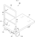
- FIG. 1 is a perspective view of an electric moving vehicle according to an example embodiment
- FIG. 2 is a diagram illustrating a configuration of an electric moving vehicle according to an example embodiment.
- FIGS. 1 and 2 an electric moving vehicle 100 according to an example embodiment is described with reference to FIGS. 1 and 2 .
- the electric moving vehicle 100 is configured to load goods to be transported and move the loaded goods, and includes a single pair of driving wheels including a left driving wheel 111a and a right driving wheel 11 1b provided on the left and the right, respectively, and a single pair of electric motors including a left electric motor 112a and a right electric motor 112b configured to drive the left driving wheel 111a and the right driving wheel 11 1b, respectively, and a body configured as a deckboard 115 configured to load goods to be transported.
- the electric moving vehicle 100 further includes a grip 130 provided at one side of the body, a single pair of force detection sensors including a left force detection sensor 121 and a right force detection sensor 122 provided between a lower portion of left and right ends of the grip 130 and an upper portion of the deckboard 115 and configured to detect a force transferred from the user to the body through the grip 130, and a controller 140 configured to control driving of the left electric motor 112a and the right electric motor 112b based on the force transferred to the body.
- a grip 130 provided at one side of the body
- a single pair of force detection sensors including a left force detection sensor 121 and a right force detection sensor 122 provided between a lower portion of left and right ends of the grip 130 and an upper portion of the deckboard 115 and configured to detect a force transferred from the user to the body through the grip 130
- a controller 140 configured to control driving of the left electric motor 112a and the right electric motor 112b based on the force transferred to the body.
- the electric moving vehicle 100 may basically include a chargeable battery.
- the battery may supply power required for the electric moving vehicle 100, including driving of the left electric motor 112a and the right electric motor 112b under control of the controller 140.
- the electric moving vehicle 100 may move desired goods to a desired location conveniently in such a manner that the goods to be transported are loaded on the deckboard 115 of the body and the left driving wheel 111a and the right driving wheel 111b are driven by the left electric motor 112a and the right electric motor 112b, respectively.
- the grip 130 holdable by the user is provided on one side of the body. Accordingly, the user may apply a force in a direction in which the goods are to be transported with holding the grip 130 of the electric moving vehicle 100.
- the force detection sensors including the left and right force detection sensors 121 and 122 are provided between the left and right ends of the grip 130.
- each of the left force detection sensor 121 and the right force detection sensor 122 detects the force applied by the user to the grip 130 and transferred to the body.
- the left and right force detection sensors 121 and 122 may include a loadcell.
- a variety of sensors capable of measuring a force such as a strain gauge, may be used.
- the left force detection sensor 121 and the right force detection sensor 122 are provided on the left and the right, respectively, at one upper side of the deckboard 115 on which goods to be transported are to be loaded. Accordingly, the left and right force detection sensors 121 and 122 accurately and effectively detect the force applied by the user to the grip 130 and transferred to the body.
- a single pair of force detection sensors including the left force detection sensor 121 and the right force detection sensor 122 are provided between the left and right ends of the grip 130 and the deckboard 115 instead of being provided at an upper end of the grip 13, such that the user may control the electric moving vehicle 100 based on not a fixed location of the grip 130 but a location convenient for the user.
- the single pair of force detection sensors includes the left force detection sensor 121 configured to detect a force transferred to the left end of the grip 130 and the right force detection sensor 122 configured to detect a force transferred to the right end of the grip 130 from the force applied by the user.
- the single pair of force detection sensors including the left and right force detection sensors 121 and 122 is present in a path through which the force applied by the user is transferred, and may detect the force applied by the user.
- the electric moving vehicle 100 may detect the force applied by the user, which enables the user to easily operate the electric moving vehicle 100.
- FIG. 3 illustrates an example of a process of transferring a force applied by a user in an electric moving vehicle according to an example embodiment.
- a portion of the force applied by the user may be applied to the left, for example, direction (D), of the body through the left end of the grip 130 and the left force detection sensor 121 (direction (B)).
- a portion of the force applied by the user may be applied to the right, for example, direction (E), of the body through the right end of the grip 130 and the right force detection sensor 122 (direction (C)).
- the electric moving vehicle 100 may amplify a magnitude of the force transferred to the body and may control operations of the left and right electric motors 112a and 112b to drive the electric moving vehicle 100. Accordingly, although heavy goods are loaded, the user may easily control the electric moving vehicle 100 to move the loaded goods to a desired location.
- the electric moving vehicle 100 includes the controller 140 configured to control driving of the left and right electric motors 112a and 112b based on sensing data generated at the left and right force detection sensors 121 and 122.
- the controller 140 may be provided to the body. However, it is only an example and thus, without being limited thereto, the controller 140 may be provided to, for example, the grip 130. In addition, the controller 140 may be provided at any locations at which the controller 140 may appropriately operate.
- the controller 140 may amplify a magnitude of the force transferred to the body and control the electric motors 112a and 112b.
- a brushless DC (BLDC) motor may be used for an electric motor, such as the left electric motor 112a and the right electric motor 112b in the electric moving vehicle 100.
- any motors that enable the controller 140 to control the electric moving vehicle 100 to appropriately operate may be applied.
- the controller 140 controls current applied to the left and right electric motors 112a and 112b based on sensing data generated at the left and right force detection sensors 121 and 122, the user may intuitively and easily control the electric moving vehicle 100 to move.
- the controller 140 performs a current control in controlling driving of the left and right electric motors 112a and 112b, torque, that is, a rotational force, of the left and right electric motors 112a and 112b may occur to be proportional to the current applied to the left and right electric motors 112a and 112b. Accordingly, the user may easily control the electric moving vehicle 100 to move even using a small amount of force.
- the controller 140 may use a pulse width modulation (PWM) signal having various duties to control the current applied to the left and right electric motors 112a and 112b. That is, the controller 140 of the electric moving vehicle 100 may effectively control the current applied to the left and right electric motors 112a and 112b using the PWM signal.
- PWM pulse width modulation
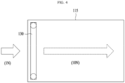
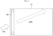
- FIGS. 4 through 6 illustrate examples of a process of driving an electric moving vehicle based on a force applied by a user in then electric moving vehicle according to an example embodiment.
- the force applied by the user may be divided into half and a half of the force may be applied to the left of the body through the left end of the grip 130 and the left force detection sensor 121. Also, another half of the force may be applied to the right of the body through the right end of the grip 130 and the right force detection sensor 122.
- each of the left force detection sensor 121 and the right force detection sensor 122 may detect a force of 0.5N.
- the controller 140 may amplify a magnitude of the force transferred to the body, that is, amplify the force of 1N to 10 N, while maintaining a driving direction of the electric moving vehicle 100 based on the force, for example, 0.5N, detected at each of the left force detection sensor 121 and the right force detection sensor 122, and may control current that is applied to the left electric motor 112a and the right electric motor 112b. Accordingly, the same magnitude of current may be applied to each of the left electric motor 112a and the right electric motor 112b.
- each of the left force detection sensor 121 and the right force detection sensor 122 may detect a force of 0.25N. Accordingly, the controller 140 may amplify a magnitude of the force transferred to the body, that is, amplify the force of 0.5N to 5N, while maintaining a driving direction of the electric moving vehicle 100 based on the force, for example, 0.25N, detected at each of the left force detection sensor 121 and the right force detection sensor 122, and may control current that is applied to the left electric motor 112a and the right electric motor 112b.
- the force applied by the user may be amplified using various methods, for example, a method of changing an amplification ratio based on an input force and a method of driving the electric moving vehicle 100 based on a preset magnitude of force, instead of applying a preset amplification ratio.
- the controller 140 may amplify a magnitude of the force applied by the user and transferred to the body while maintaining a driving direction of the electric moving vehicle 100 by the force, and may control operations of the left and right electric motors 112a and 112b. Accordingly, the user may steer the electric moving vehicle 100 in a desired direction or may control the electric moving vehicle 100 to move in an intended direction.
- the force applied by the user may be divided at a predetermined ratio based on a corresponding direction and a portion of the force may be applied to the left of the body through the left end of the grip 130 and the left force detection sensor 121 and a remaining thereof may be applied to the right of the body through the right end of the grip 130 and the right force detection sensor 122.
- the controller 140 may control current that is to be applied to the left electric motor 112a and the right electric motor 112b based on the force detected at the left force detection sensor 121 and the right force detection sensor 122, respectively.
- the controller 140 may control the current of the left electric motor 112a and the right electric motor 112b to amplify the force of a[N] so that a force of 10a[N] may be generated at the left driving wheel 111a and to amplify the force of b[N] so that a force of 10b[N] may be generated at the right driving wheel 111b.
- the controller 140 may amplify a magnitude of force finally applied by the user and transferred to the body to become 10N while maintaining a driving direction of the electric moving vehicle 100 by the force applied by the user and transferred to the body. Accordingly, the user may steer the electric moving vehicle 100 in a desired direction or may control the electric moving vehicle 100 to move in an intended direction.
- the aforementioned electric moving vehicle 100 is provided as an example only. Any type of moving vehicles operating with a battery may be included in an application target of the example embodiment.
- FIG. 7 is a diagram illustrating a configuration of components includable in a safety control apparatus according to an example embodiment.
- FIG. 7 illustrates a safety control apparatus 700 for automatic braking of the electric moving vehicle.
- the safety control apparatus 700 is a configuration included in the electric moving vehicle.
- the safety control apparatus 700 may include a manipulation detector 120, a slope detector 150, a controller 140, an electric motor 110, and a braking device 160.
- the slope detector 150 may be selectively included in or excluded from the safety control apparatus 700.
- the manipulation detector 120 detects whether a user manipulation is present based on presence or absence of a user input on the electric moving vehicle.
- the manipulation detector 120 may include a loadcell, a strain gauge, and the like, and may determine whether the user manipulation is present, that is, may detect presence or absence of the user manipulation based on the presence or absence of the user input by measuring an amount of force applied to the electric moving vehicle using such a sensor.
- the manipulation detector 120 may correspond to the left/right force detection sensor 121, 122 of FIGS. 1 and 2 .
- the manipulation detector 120 may be configured as a component separate from the left/right force detection sensor 121, 122.
- the manipulation detector 120 may be configured by providing a touch sensor on a grip of the electric moving vehicle and may detect the presence or the absence of the user manipulation according to the presence or the absence of the user input based on touch sensing data associated with the grip.
- the slope detector 150 may determine whether the electric moving vehicle is located on a slope.
- the slope detector 150 may include an inertial sensor, and may use various sensors, for example, an acceleration sensor, a gravity sensor, a gyroscope, and a geomagnetic sensor, capable of detecting a change in a gradient of a vehicle body.
- the slope detector 150 may determine whether the electric moving vehicle is located on a flatland or the slope by detecting a gradient from a reference axis corresponding to a direction of gravity.
- the controller 140 of FIG. 7 corresponds to the controller 140 of FIGS. 1 and 2 and the electric motor 110 corresponds to the left/right electric motor 112a, 112b of FIGS. 1 and 2 .
- the controller 140 controls driving of the electric motor 110 based on a force transferred by the user to the electric moving vehicle. In particular, the controller 140 controls braking for the electric motor 110 when the user manipulation for the electric moving vehicle is absent.
- the controller 140 may perform the processor functionality of performing basic arithmetic operations, logic operations, and input/output operations, and may be configured to process instructions of a computer program.
- the instructions may be provided to the controller 140 by way of a memory included as a component of the electric moving vehicle, for example, the electric moving vehicle 100 of FIGS. 1 and 2 .
- the controller 140 may be configured to execute an instruction received according to a program code stored in a storage medium such as the memory.
- the braking device 160 refers to a device that stops driving of the electric motor 110, and may apply a softlock or a hardlock on the electric motor 110 under control of the controller 140.
- the softlock refers to a first level of braking that applies a weak brake in a state in which power consumption is not required and the hardlock refers to a second level of braking that applies a brake with a strong force through power consumption.
- the softlock applies the brake by short-circuiting a driving circuit of the electric motor 110 without supplying power to the electric motor 110. For example, in the case of using a BLDC motor for the electric motor 110, if three electrodes (UVW 3 wires) of the BLDC motor are short-circuited, a counter electromotive force occurs.
- a short brake phenomenon (refer to "http://forums.parallax.com/discussion/157445/how-would-you-short-3-wires-of-a-bldc-motor-together") that spinning of wheels, for example, the left/right driving wheel 111a, 111b of FIGS. 1 and 2 , connected to the motor stops by a predetermined force may occur.
- the hardlock may stop spinning of the wheels, for example, the left/right driving wheel 111a, 111b of FIGS. 1 and 2 , connected to the electric motor 110 with a forcible force by supplying power to the electric motor 110.
- the braking device 160 may control a moving speed of the electric motor 110 through energy consumption to reach zero by configuring a feedback loop.
- the braking device 160 for the hardlock may include a braking member in which a braking drum and a braking liner couple with each other.
- the braking drum may be provided on a power transmission shaft connected to the electric motor 110 that provides power for driving the wheels of the electric moving vehicle and the braking liner may be configured to make a contact or no contact with the braking drum. It is provided as an example only. Any braking mechanisms of stopping wheels of the electric moving vehicle with a forcible force by supplying power to the electric motor 110 may be applied.
- the safety control apparatus 700 may include a number of components greater than those of FIG. 7 .
- the safety control apparatus 700 may further include an I/O device.
- an input device may include a device, such as a keyboard and a mouse
- an output device may include a device, such as a display.
- the I/O device may be a device for interface with a device in which an input function and an output function are integrated, such as a touchscreen.
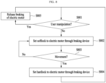
- FIG. 8 is a flowchart illustrating an example of a safety control method of an electric moving vehicle performed by a safety control apparatus according to an example embodiment.
- the safety control method of FIG. 8 may be performed by the controller 140 of the safety control apparatus of FIG. 7 .
- the controller 140 determines whether a user manipulation for an electric moving vehicle is present for example through the manipulation detector 120. That is, the controller 140 determines whether a user is currently manipulating the electric moving vehicle with holding a grip of the electric moving vehicle.
- the controller 140 initially sets a softlock to the electric motor 110 through the braking device 160.
- the braking device 160 applies a brake on the electric moving vehicle with a force by a short brake phenomenon of the electric motor 110 by short-circuiting a driving circuit of the electric motor 110, instead of supplying current to the electric motor 110.
- the controller 140 may determine whether a movement of the electric moving vehicle is present after the softlock is set.
- the controller 140 may determine whether the electric moving vehicle is still moving based on a movement of wheels or a change in a location of the electric moving vehicle in a state in which the user manipulation is continuously absent while applying the softlock.
- the controller 140 may set a hardlock to the electric motor 110 through the braking device 160.
- the braking device 160 may apply a brake by supplying power required for braking to the electric motor 110 and by configuring a feedback loop so that a moving speed of the electric motor 110 becomes zero, or may stop driving of wheels connected to the electric motor 110 with a forcible force through driving of a braking member.
- the controller 140 may release braking of the electric motor 110 by releasing the softlock or the hardlock through the braking device 160.
- the safety control apparatus may apply an automatic braking if the user is not manipulating the electric moving vehicle. That is, the safety control apparatus may apply a brake by initially applying a softlock and then, applying a hardlock if the electric moving vehicle moves even after the softlock is applied.
- FIG. 9 is a flowchart illustrating another example of a safety control method of an electric moving vehicle performed by a safety control apparatus according to an illustrative example not part of the claimed invention.
- the safety control method of FIG. 9 may be performed by the controller 140 of the safety control apparatus of FIG. 7 .
- the controller 140 may determine whether a user manipulation for an electric moving vehicle is present through the manipulation detector 120. That is, the controller 140 may determine whether a user is currently manipulating the electric moving vehicle with holding a grip of the electric moving vehicle.
- the controller 140 may determine whether the electric moving vehicle is located on a slope through the slope detector 150. The controller 140 may determine whether the electric moving vehicle is located on a flatland or the slope in a situation in which the user is not manipulating the electric moving vehicle.
- the controller 140 may set a softlock to the electric motor 110 through the braking device 160.
- the braking device 160 may apply a brake on the electric moving vehicle with a force by a short brake phenomenon of the electric motor 110 by short-circuiting a driving circuit of the electric motor 110, instead of supplying current to the electric motor 110.
- the controller 140 may set a hardlock to the electric motor 110 through the braking device 160.
- the braking device 160 may apply a brake by supplying power required for braking to the electric motor 110 and by configuring a feedback loop so that a moving speed of the electric motor 110 becomes zero, or may stop driving of wheels connected to the electric motor 110 with a forcible force through driving of a braking member.
- the safety control apparatus may distinguish a flatland situation from a slope situation when the user is not manipulating the electric moving vehicle and may apply a brake by applying a softlock in the case of the flatland situation and by applying a hardlock in the case of the slope situation.
- the safety control apparatus may apply an automatic braking on the electric moving vehicle when the user is not manipulating the electric moving vehicle.
- the safety control apparatus may employ a sequential braking scheme of initially applying the softlock without distinguishing the flatland situation and the slope situation, and then applying the hardlock if the electric moving vehicle still moves, or a selective braking scheme of distinguishing the flatland situation and the slope situation, and applying the softlock in the case of the flatland situation and applying the hardlock in the case of the slope situation. If the braking is possible even with the softlock, for example, in the case of the flatland situation, there is no need to supply power for braking. Accordingly, it is possible to reduce an amount of power consumed by the electric moving vehicle.
- the systems or apparatuses described herein may be implemented using hardware components, software components, and/or a combination thereof.
- the apparatuses and the components described herein may be implemented using one or more general-purpose or special purpose computers, such as, for example, a processor, a controller, an arithmetic logic unit (ALU), a digital signal processor, a microcomputer, a field programmable gate array (FPGA), a programmable logic unit (PLU), a microprocessor, or any other device capable of responding to and executing instructions in a defined manner.
- the processing device may run an operating system (OS) and one or more software applications that run on the OS.
- the processing device also may access, store, manipulate, process, and create data in response to execution of the software.
- OS operating system
- the processing device also may access, store, manipulate, process, and create data in response to execution of the software.
- a processing device may include multiple processing elements and/or multiple types of processing elements.
- a processing device may include multiple processors or a processor and a controller.
- different processing configurations are possible, such as parallel processors.
- the software may include a computer program, a piece of code, an instruction, or some combination thereof, for independently or collectively instructing or configuring the processing device to operate as desired.
- Software and data may be embodied permanently or temporarily in any type of machine, component, physical or virtual equipment, computer storage medium or device, or in a propagated signal wave capable of providing instructions or data to or being interpreted by the processing device.
- the software also may be distributed over network coupled computer systems so that the software is stored and executed in a distributed fashion.
- the software and data may be stored by one or more computer readable storage mediums.
- the methods according to the above-described example embodiments may be recorded in non-transitory computer-readable media including program instructions to implement various operations of the above-described example embodiments.
- the media may also include, alone or in combination with the program instructions, data files, data structures, and the like.
- the program instructions recorded on the media may be those specially designed and constructed for the purposes of example embodiments, or they may be of the kind well-known and available to those having skill in the computer software arts.
- non-transitory computer-readable media examples include magnetic media such as hard disks, floppy disks, and magnetic tapes; optical media such as CD-ROM discs, and DVDs; magneto-optical media such as floptical disks; and hardware devices that are specially configured to store and perform program instructions, such as read-only memory (ROM), random access memory (RAM), flash memory, and the like.
- program instructions include both machine code, such as produced by a compiler, and files containing higher level code that may be executed by the computer using an interpreter.
- the above-described devices may be configured to act as one or more software modules in order to perform the operations of the above-described example embodiments, or vice versa.
Landscapes
- Engineering & Computer Science (AREA)
- Transportation (AREA)
- Mechanical Engineering (AREA)
- Chemical & Material Sciences (AREA)
- Combustion & Propulsion (AREA)
- Power Engineering (AREA)
- Life Sciences & Earth Sciences (AREA)
- Sustainable Development (AREA)
- Sustainable Energy (AREA)
- Electric Propulsion And Braking For Vehicles (AREA)
- Handcart (AREA)
Description
- The following description of example embodiments relates to a technology for stopping driving of a moving vehicle.
- As background,
EP3153147A1 describes an electric vehicle and control method thereof;WO2016/158558A1 describes a walking assistance vehicle and program for control of walking assistance vehicle;US 2014 0246261 A1 describes an electric assist cart - Currently, moving vehicles are used to carry goods for various purposes in various fields, such as, for example, shopping malls, home delivery services, and industrial sites.
- For example,
Korean Utility Model Registration NO. 20-0440927 registered on July 2, 2008 Korean patent application NO. 20140136636A - When heavy goods are loaded on a moving vehicle, a user needs to use a considerable amount of force to move the moving vehicle. Further, it becomes more difficulty for the user to control the moving vehicle to move in a desired direction by appropriately operating the loaded moving vehicle and the user may need to experience a significant difficulty in transporting the goods.
- Accordingly, attempts have been made to provide a method of providing a motor to a moving vehicle and driving the motor to move the moving vehicle.
- The scope of this patent is defined by the independent claims.
- At least one example embodiment provides a safety control method and apparatus that may enhance an energy efficiency of a moving vehicle for stopping driving of the moving vehicle if a user manipulation is absent, that is, if the user is not manipulating the moving vehicle.
- According to an aspect of at least one example embodiment, there is provided a safety control method of an electric moving vehicle, the safety control method including determining whether a user manipulation is present based on presence or absence of a user input on the electric moving vehicle; and braking an electric motor that drives a wheel of the electric moving vehicle using a softlock scheme of short-circuiting an electrode of the electric motor, instead of applying power to the electric motor, in response to the user manipulation determined to be absent.
- The softlock scheme may use a short brake phenomenon that a brake with a predetermined force is applied using a counter electromotive force occurring in response to short-circuiting the electrode of the electric motor.
- The braking includes applying the softlock scheme to the electric motor in response to the user manipulation determined to be absent.. The braking may further include applying a hardlock scheme of supplying power required for braking to the electric motor and forcibly braking the electric motor in response to a movement of the electric moving vehicle determined to be present in a state in which the user manipulation is absent while applying the softlock scheme.
- The braking may include determining whether the electric moving vehicle is located on a flatland or a slope based on a gradient of the electric moving vehicle in response to the user manipulation determined to be absent; applying the softlock scheme to the electric motor in response to the electric moving vehicle determined to be located on the flatland; and applying a hardlock scheme of applying power required for braking to the electric motor and forcibly braking the electric motor in response to the electric moving vehicle determined to be located on the slope.
- The hardlock scheme may control a moving speed of the electric motor to reach zero by configuring a feedback loop.
- The determining may include determining whether the user manipulation is present by measuring an amount of force applied to the electric moving vehicle.
- The electric moving vehicle is configured as a moving transportation structure on which a user is boarded.
- According to an aspect of at least one example embodiment, there is provided a safety control apparatus of an electric moving vehicle, the safety control apparatus including a manipulation detector configured to determine whether a user manipulation is present based on presence or absence of a user input on the electric moving vehicle; and a controller configured to brake an electric motor that drives a wheel of the electric moving vehicle using a softlock scheme of short-circuiting an electrode of the electric motor, instead of applying power to the electric motor, in response to the user manipulation determined to be absent.
- According to some example embodiments, it is possible to enhance an energy efficiency of an electric moving vehicle by effectively controlling an amount of power consumed by a brake for stopping driving of the electric moving vehicle if a user manipulation is absent, that is, if the user is not manipulating the electric moving vehicle.
- Further areas of applicability will become apparent from the description provided herein. The description and specific examples in this summary are intended for purposes of illustration only and are not intended to limit the scope of the present disclosure.
- These and/or other aspects, features, and advantages of the invention will become apparent and more readily appreciated from the following description of embodiments, taken in conjunction with the accompanying drawings of which:
-
FIG. 1 is a perspective view of an electric moving vehicle according to an example embodiment; -
FIG. 2 is a diagram illustrating a configuration of an electric moving vehicle according to an example embodiment; -
FIG. 3 illustrates an example of a process of transferring a force applied by a user in an electric moving vehicle according to an example embodiment; -
FIGS. 4 through 6 illustrate examples of a process of driving an electric moving vehicle based on a force applied by a user in the electric moving vehicle according to an example embodiment; -
FIG. 7 is a diagram illustrating a configuration of components includable in a safety control apparatus according to an example embodiment; -
FIG. 8 is a flowchart illustrating an example of a safety control method of an electric moving vehicle performed by a safety control apparatus according to an example embodiment; and -
FIG. 9 is a flowchart illustrating another example of a safety control method of an electric moving vehicle performed by a safety control apparatus according to an example embodiment. - One or more example embodiments will be described in detail with reference to the accompanying drawings. Example embodiments, however, may be embodied in various different forms, and should not be construed as being limited to only the illustrated embodiments. Rather, the illustrated embodiments are provided as examples so that this disclosure will be thorough and complete, and will fully convey the concepts of this disclosure to those skilled in the art. Accordingly, known processes, elements, and techniques, may not be described with respect to some example embodiments. Unless otherwise noted, like reference characters denote like elements throughout the attached drawings and written description, and thus descriptions will not be repeated.
- Although the terms "first," "second," "third," etc., may be used herein to describe various elements, components, regions, layers, and/or sections, these elements, components, regions, layers, and/or sections, should not be limited by these terms. These terms are only used to distinguish one element, component, region, layer, or section, from another region, layer, or section. Thus, a first element, component, region, layer, or section, discussed below may be termed a second element, component, region, layer, or section, without departing from the scope of this disclosure.
- As used herein, the singular forms "a," "an," and "the," are intended to include the plural forms as well, unless the context clearly indicates otherwise. It will be further understood that the terms "comprises" and/or "comprising," when used in this specification, specify the presence of stated features, integers, steps, operations, elements, and/or components, but do not preclude the presence or addition of one or more other features, integers, steps, operations, elements, components, and/or groups, thereof. As used herein, the term "and/or" includes any and all combinations of one or more of the associated listed items.
- Unless otherwise defined, all terms (including technical and scientific terms) used herein have the same meaning as commonly understood by one of ordinary skill in the art to which example embodiments belong. Terms, such as those defined in commonly used dictionaries, should be interpreted as having a meaning that is consistent with their meaning in the context of the relevant art and/or this disclosure, and should not be interpreted in an idealized or overly formal sense unless expressly so defined herein.
- Hereinafter, example embodiments will be described with reference to the accompanying drawings.
- The example embodiments relate to a safety control method and apparatus that may enhance an energy efficiency of an electric moving vehicle.
- The example embodiments disclosed herein may achieve many advantages in terms of an energy efficiency and cost saving, etc., of an electric moving vehicle.
- The term "electric moving vehicle" used herein may inclusively indicate a transportation device of goods and a transportation device in a structure on which a person, for example, a user is boarded. If the electric moving device is for boarding a person, the electric moving device may include, for example, an electric wheelchair, an electric moving bed, an electric stroller, and an electric wagon. Hereinafter, the example embodiments will be described using the transportation device of goods as a representative example, however, are not limited thereto.
-
FIG. 1 is a perspective view of an electric moving vehicle according to an example embodiment, andFIG. 2 is a diagram illustrating a configuration of an electric moving vehicle according to an example embodiment. - Hereinafter, an electric moving
vehicle 100 according to an example embodiment is described with reference toFIGS. 1 and2 . - Referring to
FIGS. 1 and2 , the electric movingvehicle 100 is configured to load goods to be transported and move the loaded goods, and includes a single pair of driving wheels including a leftdriving wheel 111a and a right driving wheel 11 1b provided on the left and the right, respectively, and a single pair of electric motors including a leftelectric motor 112a and a rightelectric motor 112b configured to drive the leftdriving wheel 111a and the right driving wheel 11 1b, respectively, and a body configured as adeckboard 115 configured to load goods to be transported. - The electric moving
vehicle 100 further includes agrip 130 provided at one side of the body, a single pair of force detection sensors including a leftforce detection sensor 121 and a rightforce detection sensor 122 provided between a lower portion of left and right ends of thegrip 130 and an upper portion of thedeckboard 115 and configured to detect a force transferred from the user to the body through thegrip 130, and acontroller 140 configured to control driving of the leftelectric motor 112a and the rightelectric motor 112b based on the force transferred to the body. - Although not illustrated in detail, the electric moving
vehicle 100 may basically include a chargeable battery. Here, the battery may supply power required for the electric movingvehicle 100, including driving of the leftelectric motor 112a and the rightelectric motor 112b under control of thecontroller 140. - According to the above configuration, the electric moving
vehicle 100 may move desired goods to a desired location conveniently in such a manner that the goods to be transported are loaded on thedeckboard 115 of the body and the leftdriving wheel 111a and the right drivingwheel 111b are driven by the leftelectric motor 112a and the rightelectric motor 112b, respectively. - In the electric moving
vehicle 100, thegrip 130 holdable by the user is provided on one side of the body. Accordingly, the user may apply a force in a direction in which the goods are to be transported with holding thegrip 130 of the electric movingvehicle 100. - In the electric moving
vehicle 100, the force detection sensors including the left and rightforce detection sensors grip 130. Here, each of the leftforce detection sensor 121 and the rightforce detection sensor 122 detects the force applied by the user to thegrip 130 and transferred to the body. Here, the left and rightforce detection sensors - Referring to
FIG. 1 , the leftforce detection sensor 121 and the rightforce detection sensor 122 are provided on the left and the right, respectively, at one upper side of thedeckboard 115 on which goods to be transported are to be loaded. Accordingly, the left and rightforce detection sensors grip 130 and transferred to the body. - In the aforementioned
electric moving vehicle 100, a single pair of force detection sensors including the leftforce detection sensor 121 and the rightforce detection sensor 122 are provided between the left and right ends of thegrip 130 and thedeckboard 115 instead of being provided at an upper end of the grip 13, such that the user may control the electric movingvehicle 100 based on not a fixed location of thegrip 130 but a location convenient for the user. - In detail, the single pair of force detection sensors includes the left
force detection sensor 121 configured to detect a force transferred to the left end of thegrip 130 and the rightforce detection sensor 122 configured to detect a force transferred to the right end of thegrip 130 from the force applied by the user. Accordingly, in the electric movingvehicle 100, the single pair of force detection sensors including the left and rightforce detection sensors vehicle 100 may detect the force applied by the user, which enables the user to easily operate the electric movingvehicle 100. -
FIG. 3 illustrates an example of a process of transferring a force applied by a user in an electric moving vehicle according to an example embodiment. - Hereinafter, operations of the left and right
force detection sensors FIG. 3 . - Referring to
FIG. 3 , if the user applies a force in a direction, for example, direction (A), in which loaded goods are to be transported with holding thegrip 130 using a single hand or both hands, a portion of the force applied by the user may be applied to the left, for example, direction (D), of the body through the left end of thegrip 130 and the left force detection sensor 121 (direction (B)). Also, a portion of the force applied by the user may be applied to the right, for example, direction (E), of the body through the right end of thegrip 130 and the right force detection sensor 122 (direction (C)). - According to an example embodiment, while maintaining a driving direction of the electric moving
vehicle 100 by a force applied by the user to thegrip 130 and transferred to the body, the electric movingvehicle 100 may amplify a magnitude of the force transferred to the body and may control operations of the left and rightelectric motors vehicle 100. Accordingly, although heavy goods are loaded, the user may easily control the electric movingvehicle 100 to move the loaded goods to a desired location. - The electric moving
vehicle 100 includes thecontroller 140 configured to control driving of the left and rightelectric motors force detection sensors controller 140 may be provided to the body. However, it is only an example and thus, without being limited thereto, thecontroller 140 may be provided to, for example, thegrip 130. In addition, thecontroller 140 may be provided at any locations at which thecontroller 140 may appropriately operate. - While maintaining a driving direction of the electric moving
vehicle 100 by a force applied by the user to thegrip 130 and transferred to the body, thecontroller 140 may amplify a magnitude of the force transferred to the body and control theelectric motors electric motor 112a and the rightelectric motor 112b in the electric movingvehicle 100. In addition, any motors that enable thecontroller 140 to control the electric movingvehicle 100 to appropriately operate may be applied. - Since the
controller 140 controls current applied to the left and rightelectric motors force detection sensors vehicle 100 to move. Here, if thecontroller 140 performs a current control in controlling driving of the left and rightelectric motors electric motors electric motors vehicle 100 to move even using a small amount of force. Thecontroller 140 may use a pulse width modulation (PWM) signal having various duties to control the current applied to the left and rightelectric motors controller 140 of the electric movingvehicle 100 may effectively control the current applied to the left and rightelectric motors -
FIGS. 4 through 6 illustrate examples of a process of driving an electric moving vehicle based on a force applied by a user in then electric moving vehicle according to an example embodiment. - Referring to
FIG. 4 , if the user vertically applies a force to thegrip 130 to make the electric movingvehicle 100 move forward, for example, if the user applies a force of 1N, the force applied by the user may be divided into half and a half of the force may be applied to the left of the body through the left end of thegrip 130 and the leftforce detection sensor 121. Also, another half of the force may be applied to the right of the body through the right end of thegrip 130 and the rightforce detection sensor 122. Here, each of the leftforce detection sensor 121 and the rightforce detection sensor 122 may detect a force of 0.5N. Accordingly, thecontroller 140 may amplify a magnitude of the force transferred to the body, that is, amplify the force of 1N to 10 N, while maintaining a driving direction of the electric movingvehicle 100 based on the force, for example, 0.5N, detected at each of the leftforce detection sensor 121 and the rightforce detection sensor 122, and may control current that is applied to the leftelectric motor 112a and the rightelectric motor 112b. Accordingly, the same magnitude of current may be applied to each of the leftelectric motor 112a and the rightelectric motor 112b. - Referring to
FIG. 5 , if the user applies a force to thegrip 130 in a pulling direction to make the electric movingvehicle 100 slowly move backward, for example, if the user applies a force of 0.5N, each of the leftforce detection sensor 121 and the rightforce detection sensor 122 may detect a force of 0.25N. Accordingly, thecontroller 140 may amplify a magnitude of the force transferred to the body, that is, amplify the force of 0.5N to 5N, while maintaining a driving direction of the electric movingvehicle 100 based on the force, for example, 0.25N, detected at each of the leftforce detection sensor 121 and the rightforce detection sensor 122, and may control current that is applied to the leftelectric motor 112a and the rightelectric motor 112b. - According to an example embodiment, in the case of driving the electric moving
vehicle 100 by amplifying a force applied by the user, the force applied by the user may be amplified using various methods, for example, a method of changing an amplification ratio based on an input force and a method of driving the electric movingvehicle 100 based on a preset magnitude of force, instead of applying a preset amplification ratio. - Further, referring to
FIG. 6 , in the electric movingvehicle 100 according to an example embodiment, although the user applies a force in a direction inclined relative to a forward/backward direction, thecontroller 140 may amplify a magnitude of the force applied by the user and transferred to the body while maintaining a driving direction of the electric movingvehicle 100 by the force, and may control operations of the left and rightelectric motors vehicle 100 in a desired direction or may control the electric movingvehicle 100 to move in an intended direction. - In detail, referring to
FIG. 6 , if the user applies a force to thegrip 130 in a desired direction, for example, applies a force of 1N, the force applied by the user may be divided at a predetermined ratio based on a corresponding direction and a portion of the force may be applied to the left of the body through the left end of thegrip 130 and the leftforce detection sensor 121 and a remaining thereof may be applied to the right of the body through the right end of thegrip 130 and the rightforce detection sensor 122. Here, if the leftforce detection sensor 121 detects a force of a[N] and the rightforce detection sensor 122 detects a force of b[N], thecontroller 140 may control current that is to be applied to the leftelectric motor 112a and the rightelectric motor 112b based on the force detected at the leftforce detection sensor 121 and the rightforce detection sensor 122, respectively. - For example, the
controller 140 may control the current of the leftelectric motor 112a and the rightelectric motor 112b to amplify the force of a[N] so that a force of 10a[N] may be generated at theleft driving wheel 111a and to amplify the force of b[N] so that a force of 10b[N] may be generated at theright driving wheel 111b. Thecontroller 140 may amplify a magnitude of force finally applied by the user and transferred to the body to become 10N while maintaining a driving direction of the electric movingvehicle 100 by the force applied by the user and transferred to the body. Accordingly, the user may steer the electric movingvehicle 100 in a desired direction or may control the electric movingvehicle 100 to move in an intended direction. - The aforementioned
electric moving vehicle 100 is provided as an example only. Any type of moving vehicles operating with a battery may be included in an application target of the example embodiment. - Hereinafter, a method and apparatus for safety control of an electric moving vehicle according to example embodiments will be further described.
-
FIG. 7 is a diagram illustrating a configuration of components includable in a safety control apparatus according to an example embodiment. - An electric moving vehicle requires an automatic braking in response to a location control or a speed control when a person, for example, a user is not operating an electric moving vehicle.
FIG. 7 illustrates asafety control apparatus 700 for automatic braking of the electric moving vehicle. Here, thesafety control apparatus 700 is a configuration included in the electric moving vehicle. - Referring to
FIG. 7 , thesafety control apparatus 700 may include amanipulation detector 120, aslope detector 150, acontroller 140, anelectric motor 110, and abraking device 160. Depending on example embodiments, theslope detector 150 may be selectively included in or excluded from thesafety control apparatus 700. - The
manipulation detector 120 detects whether a user manipulation is present based on presence or absence of a user input on the electric moving vehicle. For example, themanipulation detector 120 may include a loadcell, a strain gauge, and the like, and may determine whether the user manipulation is present, that is, may detect presence or absence of the user manipulation based on the presence or absence of the user input by measuring an amount of force applied to the electric moving vehicle using such a sensor. Here, themanipulation detector 120 may correspond to the left/rightforce detection sensor FIGS. 1 and2 . As another example, themanipulation detector 120 may be configured as a component separate from the left/rightforce detection sensor manipulation detector 120 may be configured by providing a touch sensor on a grip of the electric moving vehicle and may detect the presence or the absence of the user manipulation according to the presence or the absence of the user input based on touch sensing data associated with the grip. - The
slope detector 150 may determine whether the electric moving vehicle is located on a slope. Here, theslope detector 150 may include an inertial sensor, and may use various sensors, for example, an acceleration sensor, a gravity sensor, a gyroscope, and a geomagnetic sensor, capable of detecting a change in a gradient of a vehicle body. Theslope detector 150 may determine whether the electric moving vehicle is located on a flatland or the slope by detecting a gradient from a reference axis corresponding to a direction of gravity. - The
controller 140 ofFIG. 7 corresponds to thecontroller 140 ofFIGS. 1 and2 and theelectric motor 110 corresponds to the left/rightelectric motor FIGS. 1 and2 . Thecontroller 140 controls driving of theelectric motor 110 based on a force transferred by the user to the electric moving vehicle. In particular, thecontroller 140 controls braking for theelectric motor 110 when the user manipulation for the electric moving vehicle is absent. - Here, the
controller 140 may perform the processor functionality of performing basic arithmetic operations, logic operations, and input/output operations, and may be configured to process instructions of a computer program. The instructions may be provided to thecontroller 140 by way of a memory included as a component of the electric moving vehicle, for example, the electric movingvehicle 100 ofFIGS. 1 and2 . For example, thecontroller 140 may be configured to execute an instruction received according to a program code stored in a storage medium such as the memory. - The
braking device 160 refers to a device that stops driving of theelectric motor 110, and may apply a softlock or a hardlock on theelectric motor 110 under control of thecontroller 140. Here, the softlock refers to a first level of braking that applies a weak brake in a state in which power consumption is not required and the hardlock refers to a second level of braking that applies a brake with a strong force through power consumption. The softlock applies the brake by short-circuiting a driving circuit of theelectric motor 110 without supplying power to theelectric motor 110. For example, in the case of using a BLDC motor for theelectric motor 110, if three electrodes (UVW 3 wires) of the BLDC motor are short-circuited, a counter electromotive force occurs. Accordingly, a short brake phenomenon (refer to "http://forums.parallax.com/discussion/157445/how-would-you-short-3-wires-of-a-bldc-motor-together") that spinning of wheels, for example, the left/right driving wheel FIGS. 1 and2 , connected to the motor stops by a predetermined force may occur. The hardlock may stop spinning of the wheels, for example, the left/right driving wheel FIGS. 1 and2 , connected to theelectric motor 110 with a forcible force by supplying power to theelectric motor 110. For example, thebraking device 160 may control a moving speed of theelectric motor 110 through energy consumption to reach zero by configuring a feedback loop. As another example, thebraking device 160 for the hardlock may include a braking member in which a braking drum and a braking liner couple with each other. Here, the braking drum may be provided on a power transmission shaft connected to theelectric motor 110 that provides power for driving the wheels of the electric moving vehicle and the braking liner may be configured to make a contact or no contact with the braking drum. It is provided as an example only. Any braking mechanisms of stopping wheels of the electric moving vehicle with a forcible force by supplying power to theelectric motor 110 may be applied. - According to other example embodiments, the
safety control apparatus 700 may include a number of components greater than those ofFIG. 7 . Thesafety control apparatus 700 may further include an I/O device. For example, an input device may include a device, such as a keyboard and a mouse, and an output device may include a device, such as a display. As another example, the I/O device may be a device for interface with a device in which an input function and an output function are integrated, such as a touchscreen. However, there is no need to clearly illustrate many conventional components. -
FIG. 8 is a flowchart illustrating an example of a safety control method of an electric moving vehicle performed by a safety control apparatus according to an example embodiment. The safety control method ofFIG. 8 may be performed by thecontroller 140 of the safety control apparatus ofFIG. 7 . - Referring to
FIG. 8 , in operation S801, thecontroller 140 determines whether a user manipulation for an electric moving vehicle is present for example through themanipulation detector 120. That is, thecontroller 140 determines whether a user is currently manipulating the electric moving vehicle with holding a grip of the electric moving vehicle. - In operation S802, if the user is not manipulating the electric moving vehicle, the
controller 140 initially sets a softlock to theelectric motor 110 through thebraking device 160. Here, thebraking device 160 applies a brake on the electric moving vehicle with a force by a short brake phenomenon of theelectric motor 110 by short-circuiting a driving circuit of theelectric motor 110, instead of supplying current to theelectric motor 110. - In operation S803, the
controller 140 may determine whether a movement of the electric moving vehicle is present after the softlock is set. Thecontroller 140 may determine whether the electric moving vehicle is still moving based on a movement of wheels or a change in a location of the electric moving vehicle in a state in which the user manipulation is continuously absent while applying the softlock. - In operation S804, if the electric moving vehicle moves even after the softlock is set, the
controller 140 may set a hardlock to theelectric motor 110 through thebraking device 160. Here, thebraking device 160 may apply a brake by supplying power required for braking to theelectric motor 110 and by configuring a feedback loop so that a moving speed of theelectric motor 110 becomes zero, or may stop driving of wheels connected to theelectric motor 110 with a forcible force through driving of a braking member. - In operation S805, if the user manipulation is present, that is, if the user is manipulating the electric moving vehicle, the
controller 140 may release braking of theelectric motor 110 by releasing the softlock or the hardlock through thebraking device 160. - As described above, according to example embodiments, the safety control apparatus may apply an automatic braking if the user is not manipulating the electric moving vehicle. That is, the safety control apparatus may apply a brake by initially applying a softlock and then, applying a hardlock if the electric moving vehicle moves even after the softlock is applied.
-
FIG. 9 is a flowchart illustrating another example of a safety control method of an electric moving vehicle performed by a safety control apparatus according to an illustrative example not part of the claimed invention. - The safety control method of
FIG. 9 may be performed by thecontroller 140 of the safety control apparatus ofFIG. 7 . - Referring to
FIG. 9 , in operation S901, thecontroller 140 may determine whether a user manipulation for an electric moving vehicle is present through themanipulation detector 120. That is, thecontroller 140 may determine whether a user is currently manipulating the electric moving vehicle with holding a grip of the electric moving vehicle. - In operation S902, if the user is not manipulating the electric moving vehicle, the
controller 140 may determine whether the electric moving vehicle is located on a slope through theslope detector 150. Thecontroller 140 may determine whether the electric moving vehicle is located on a flatland or the slope in a situation in which the user is not manipulating the electric moving vehicle. - In operation S903, if the electric moving vehicle is determined to be located on the flatland, the
controller 140 may set a softlock to theelectric motor 110 through thebraking device 160. Here, thebraking device 160 may apply a brake on the electric moving vehicle with a force by a short brake phenomenon of theelectric motor 110 by short-circuiting a driving circuit of theelectric motor 110, instead of supplying current to theelectric motor 110. - In operation S904, if the electric moving vehicle is determined to be located on the slope, the
controller 140 may set a hardlock to theelectric motor 110 through thebraking device 160. Here, thebraking device 160 may apply a brake by supplying power required for braking to theelectric motor 110 and by configuring a feedback loop so that a moving speed of theelectric motor 110 becomes zero, or may stop driving of wheels connected to theelectric motor 110 with a forcible force through driving of a braking member. - In operation S905, if the user manipulation is present, that is, if the user is manipulating the electric moving vehicle, the
controller 140 may release braking of theelectric motor 110 by releasing the softlock or the hardlock through thebraking device 160. - As described above, according to illustrative examples not part of the claimed invention, the safety control apparatus may distinguish a flatland situation from a slope situation when the user is not manipulating the electric moving vehicle and may apply a brake by applying a softlock in the case of the flatland situation and by applying a hardlock in the case of the slope situation.
- In detail, the safety control apparatus may apply an automatic braking on the electric moving vehicle when the user is not manipulating the electric moving vehicle. Here, the safety control apparatus may employ a sequential braking scheme of initially applying the softlock without distinguishing the flatland situation and the slope situation, and then applying the hardlock if the electric moving vehicle still moves, or a selective braking scheme of distinguishing the flatland situation and the slope situation, and applying the softlock in the case of the flatland situation and applying the hardlock in the case of the slope situation. If the braking is possible even with the softlock, for example, in the case of the flatland situation, there is no need to supply power for braking. Accordingly, it is possible to reduce an amount of power consumed by the electric moving vehicle.
- According to example embodiments, it is possible to enhance an energy efficiency of an electric moving vehicle by effectively controlling an amount of power consumed by a brake for stopping driving of the electric moving vehicle if a user manipulation is absent.
- The systems or apparatuses described herein may be implemented using hardware components, software components, and/or a combination thereof. For example, the apparatuses and the components described herein may be implemented using one or more general-purpose or special purpose computers, such as, for example, a processor, a controller, an arithmetic logic unit (ALU), a digital signal processor, a microcomputer, a field programmable gate array (FPGA), a programmable logic unit (PLU), a microprocessor, or any other device capable of responding to and executing instructions in a defined manner. The processing device may run an operating system (OS) and one or more software applications that run on the OS. The processing device also may access, store, manipulate, process, and create data in response to execution of the software. For purpose of simplicity, the description of a processing device is used as singular; however, one skilled in the art will be appreciated that a processing device may include multiple processing elements and/or multiple types of processing elements. For example, a processing device may include multiple processors or a processor and a controller. In addition, different processing configurations are possible, such as parallel processors.
- The software may include a computer program, a piece of code, an instruction, or some combination thereof, for independently or collectively instructing or configuring the processing device to operate as desired. Software and data may be embodied permanently or temporarily in any type of machine, component, physical or virtual equipment, computer storage medium or device, or in a propagated signal wave capable of providing instructions or data to or being interpreted by the processing device. The software also may be distributed over network coupled computer systems so that the software is stored and executed in a distributed fashion. In particular, the software and data may be stored by one or more computer readable storage mediums.
- The methods according to the above-described example embodiments may be recorded in non-transitory computer-readable media including program instructions to implement various operations of the above-described example embodiments. The media may also include, alone or in combination with the program instructions, data files, data structures, and the like. The program instructions recorded on the media may be those specially designed and constructed for the purposes of example embodiments, or they may be of the kind well-known and available to those having skill in the computer software arts. Examples of non-transitory computer-readable media include magnetic media such as hard disks, floppy disks, and magnetic tapes; optical media such as CD-ROM discs, and DVDs; magneto-optical media such as floptical disks; and hardware devices that are specially configured to store and perform program instructions, such as read-only memory (ROM), random access memory (RAM), flash memory, and the like. Examples of program instructions include both machine code, such as produced by a compiler, and files containing higher level code that may be executed by the computer using an interpreter. The above-described devices may be configured to act as one or more software modules in order to perform the operations of the above-described example embodiments, or vice versa.
- A number of embodiments and illustrative examples not part of the claimed invention have been described above. Nevertheless, it should be understood that various modifications may be made to the embodiments. For example, suitable results may be achieved if the described techniques are performed in a different order and/or if components in a described system, architecture, device, or circuit are combined in a different manner and/or replaced or supplemented by other components or their equivalents. The scope is determined by the appended claims.
Claims (15)
- A safety control method of an electric moving vehicle configured to load goods to be transported or configured as a moving transportation structure on which a person
is boarded, the safety control method comprising:detecting a force transferred from a user to a body of the vehicle through a grip (130) holdable by the user, wherein the body is configured as a deckboard, wherein the grip (130) is provided at one side of the body, wherein the force is detected by a pair of force detection sensors including a left force detection sensor (121) and a right force detection sensor (122) provided between a lower portion of left and right ends of the grip (130) and an upper portion of the deckboard (115);determining whether a user manipulation is present or absent based on presence or absence of a user input on the electric moving vehicle, wherein the presence or absence of user input is determined by measuring the detected force or using a touch sensor on the grip of the electric moving vehicle;in response to the user manipulation determined to be present,controlling a left electric motor (112a) driving a left driving wheel (111a) based on a force detected by the left force detection sensor (121) andcontrolling a right electric motor (112b) driving a right driving wheel (111b) based on a force detected by the right force detection sensor (122); andbraking the electric moving vehicle in response to the user manipulation determined to be absent, wherein the braking comprises applying a softlock scheme to at least one of the left electric motor (112a) and the right electric motor (112b), consisting in short-circuiting an electrode of the electric motor without applying power to the electric motor in response to the user manipulation determined to be absent. - The safety control method of claim 1, wherein the softlock scheme uses a short brake phenomenon that a brake with a predetermined force is applied using a counter electromotive force occurring in response to short-circuiting the electrode of the electric motor.
- The safety control method of claim 1, wherein the braking comprises:initially applying a softlock scheme to the electric motor in response to the user manipulation determined to be absent; andapplying a hardlock scheme of supplying power required for braking to the electric motor and forcibly braking the electric motor in response to a movement of the electric moving vehicle determined to be present in a state in which the user manipulation is absent while applying the softlock scheme.
- The safety control method of any of the preceding claims, wherein the braking comprises:determining whether the electric moving vehicle is located on a flatland or a slope based on a gradient of the electric moving vehicle in response to the user manipulation determined to be absent;applying the softlock scheme to the electric motor in response to the electric moving vehicle determined to be located on the flatland; andapplying a hardlock scheme of applying power required for braking to the electric motor and forcibly braking the electric motor in response to the electric moving vehicle determined to be located on the slope.
- The safety control method of claim 3 or 4, wherein the hardlock scheme controls a moving speed of the respective electric motor through energy consumption to reach zero by a feedback loop in the power applied to the electric motor.
- The safety control method of any of the preceding claims, wherein the force detection sensors include a loadcell or strain gauge
- The safety control method of any of the preceding claims, wherein the lower portions of the left and right ends of the grip (130) including the force detection sensors (121,122) extend down to the deckboard (115).
- A safety control apparatus of an electric moving vehicle, the safety control apparatus comprising:a grip (130) holdable by a user provided at one side of the body of the vehicle;a body configured as a deckboard (115) for goods to be transported or for boarding a person;a pair of force detection sensors including a left (121) and a right force detection sensor (122) provided between a lower portion of left and right ends of the grip (130) and an upper portion of the deckboard (115) of the vehicle for loading goods;a left electric motor (112a) configured to drive a left driving wheel (111a);a right electric motor (112b) configured to drive a right driving wheel (111b); anda controller (140) configured to drive the left driving wheel (111a) based on a force detected by the left force detection sensor (121), to drive the right driving wheel (111b) based on a force detected by the right force detection sensor (122), and to brake the electric moving vehicle in response to user input determined to be absent, wherein the presence or absence of user input is determined by measuring the detected force or using a touch sensor on the grip of the electric moving vehicle, wherein the braking comprises applying a softlock scheme to at least one of the left electric motor (112a) and the right electric motor (112b), consisting in short-circuiting an electrode of the electric motor without applying power to the electric motor in response to the user manipulation determined to be absent.
- The safety control apparatus of claim 8, wherein the softlock scheme uses a short brake phenomenon that a brake with a predetermined force is applied using a counter electromotive force occurring in response to short-circuiting the electrode of the electric motor.
- The safety control apparatus of claim 8, wherein the controller is configured toinitially apply a softlock scheme to the electric motor in response to the user manipulation determined to be absent, andapplying a hardlock scheme of supplying power required for braking to the electric motor and forcibly braking the electric motor in response to a movement of the electric moving vehicle determined to be present in a state in which the user manipulation is absent while applying the softlock scheme.
- The safety control apparatus of any of claims 8-10, further comprising:a slope detector configured to determine whether the electric moving vehicle is located on a flatland or a slope based on a gradient of the electric moving vehicle in response to the user manipulation determined to be absent,wherein the controller is configured toapply the softlock scheme to the electric motor in response to the electric moving vehicle determined to be located on the flatland, andapply a hardlock scheme of applying the power required for braking to the electric motor and forcibly braking the electric motor in response to the electric moving vehicle determined to be located on the slope.
- The safety control apparatus of claim 10 or 11, wherein the hardlock scheme controls a moving speed of the electric motor through energy consumption to reach zero by a feedback loop in the power applied to the electric motor.
- The safety control apparatus of any of claims 8 - 12, wherein the force detection sensors include a loadcell or strain gauge.
- The safety control apparatus of claims 13, wherein lower portions of the left and right ends of the grip (130) including the force detection sensors (121,122) extend down to the deckboard (115).
- A non-transitory computer-readable media storing instructions that, when executed by the apparatus according to any of claims 8-14, cause the apparatus to perform the method according to any of claims 1-7.
Applications Claiming Priority (1)
| Application Number | Priority Date | Filing Date | Title |
|---|---|---|---|
| KR1020170102896A KR101939144B1 (en) | 2017-08-14 | 2017-08-14 | Method and apparatus for safety control of electric moving vehicle |
Publications (2)
| Publication Number | Publication Date |
|---|---|
| EP3444141A1 EP3444141A1 (en) | 2019-02-20 |
| EP3444141B1 true EP3444141B1 (en) | 2023-12-13 |
Family
ID=60810196
Family Applications (1)
| Application Number | Title | Priority Date | Filing Date |
|---|---|---|---|
| EP18188649.0A Active EP3444141B1 (en) | 2017-08-14 | 2018-08-13 | Method and apparatus for safety control of electric moving vehicle |
Country Status (5)
| Country | Link |
|---|---|
| US (1) | US11571973B2 (en) |
| EP (1) | EP3444141B1 (en) |
| KR (1) | KR101939144B1 (en) |
| CN (1) | CN111094105B (en) |
| WO (1) | WO2019035537A1 (en) |
Families Citing this family (12)
| Publication number | Priority date | Publication date | Assignee | Title |
|---|---|---|---|---|
| US11555576B2 (en) | 2014-12-24 | 2023-01-17 | Veltek Associates, Inc. | Stationary transfer platform and cleaning device for supply transport device |
| USD809730S1 (en) | 2015-12-22 | 2018-02-06 | Veltek Associates, Inc. | Cart |
| KR102142145B1 (en) * | 2019-03-26 | 2020-08-06 | 유근민 | Electirc baby carriagel |
| EP3999398A1 (en) | 2019-07-16 | 2022-05-25 | CYBEX GmbH | Pram |
| US12539905B2 (en) * | 2019-09-18 | 2026-02-03 | Cybex Gmbh | Stroller or stroller frame having a motor and having a control unit for supporting the drive with force sensor calibration, method for controlling the motor, and computer-readable storage medium |
| US11535465B2 (en) * | 2019-09-25 | 2022-12-27 | Jeffrey Lawrence Kinzler | Urban intermodal freight system for cities with mass transit rail infrastructure |
| KR102448856B1 (en) | 2020-12-29 | 2022-09-30 | 동서대학교 산학협력단 | Carrier and trolley management system that can track indoor location |
| JP7720176B2 (en) * | 2021-06-16 | 2025-08-07 | 株式会社マキタ | Electric transport vehicle |
| CN114642503A (en) * | 2022-03-10 | 2022-06-21 | 杭州唯精医疗机器人有限公司 | Medical instrument movement control system and method |
| US11904924B1 (en) * | 2022-07-27 | 2024-02-20 | Logistics And Supply Chain Multitech R & D Centre Limited | Motorised trolley |
| EP4321433A3 (en) * | 2022-08-11 | 2024-04-03 | B/E Aerospace, Inc. | Aircraft catering systems, methods, and devices |
| EP4652085A1 (en) * | 2023-01-17 | 2025-11-26 | Definitive Technology Group, LLC | Powered warehouse carts and methods of using the same |
Citations (1)
| Publication number | Priority date | Publication date | Assignee | Title |
|---|---|---|---|---|
| US20140246261A1 (en) * | 2011-10-13 | 2014-09-04 | Kayaba Industry Co., Ltd. | Electric assist cart |
Family Cites Families (16)
| Publication number | Priority date | Publication date | Assignee | Title |
|---|---|---|---|---|
| KR200303416Y1 (en) | 2002-11-02 | 2003-02-07 | 이의식 | Electromotive a baby carriage |
| JP2004284555A (en) * | 2003-03-25 | 2004-10-14 | Hoshizaki Electric Co Ltd | Carrying vehicle |
| JP2004359008A (en) * | 2003-06-02 | 2004-12-24 | Sony Corp | Carrying vehicle and controlling method thereof |
| US7870917B2 (en) * | 2004-10-25 | 2011-01-18 | Sanyo Electric Co., Ltd. | Drive device for electrically movable vehicles and electric wheelchair having same |
| KR200440927Y1 (en) | 2007-09-05 | 2008-07-09 | 고영호 | Box transport trolley |
| JP5798878B2 (en) * | 2011-10-13 | 2015-10-21 | カヤバ工業株式会社 | Transport cart |
| DE102013100088A1 (en) * | 2013-01-07 | 2014-07-10 | Rolf Strothmann | For movement by muscle power provided device, in particular vehicle |
| JP2014221086A (en) * | 2013-05-13 | 2014-11-27 | 船井電機株式会社 | Walking assist vehicle |
| KR101502975B1 (en) | 2013-05-21 | 2015-03-16 | 한국생산기술연구원 | Apparatus and mehtod for controlling cart |
| JP2015047943A (en) * | 2013-08-30 | 2015-03-16 | 船井電機株式会社 | Manual propulsion vehicle |
| JP6059279B2 (en) * | 2015-03-27 | 2017-01-11 | シャープ株式会社 | Program for controlling walking assistance vehicles and walking assistance vehicles |
| JP6812189B2 (en) * | 2015-10-05 | 2021-01-13 | ナブテスコ株式会社 | Electric vehicle and its control method |
| CN205044793U (en) * | 2015-10-19 | 2016-02-24 | 金乡县金地电力有限责任公司 | High pressure earth connection transport vechicle |
| CN105865801A (en) * | 2016-04-05 | 2016-08-17 | 无锡锐祺通讯技术有限公司 | Electric vehicle parameter automatic configuration and test system and automatic configuration and test method |
| JP6463818B2 (en) * | 2016-10-28 | 2019-02-06 | ネイバー コーポレーションNAVER Corporation | Electric mobile trolley |
| JP7389966B2 (en) * | 2019-11-22 | 2023-12-01 | スズキ株式会社 | walking aid vehicle |
-
2017
- 2017-08-14 KR KR1020170102896A patent/KR101939144B1/en active Active
-
2018
- 2018-05-28 WO PCT/KR2018/006022 patent/WO2019035537A1/en not_active Ceased
- 2018-05-28 CN CN201880050989.3A patent/CN111094105B/en active Active
- 2018-08-13 EP EP18188649.0A patent/EP3444141B1/en active Active
-
2020
- 2020-02-14 US US16/791,625 patent/US11571973B2/en active Active
Patent Citations (1)
| Publication number | Priority date | Publication date | Assignee | Title |
|---|---|---|---|---|
| US20140246261A1 (en) * | 2011-10-13 | 2014-09-04 | Kayaba Industry Co., Ltd. | Electric assist cart |
Also Published As
| Publication number | Publication date |
|---|---|
| US11571973B2 (en) | 2023-02-07 |
| US20200180439A1 (en) | 2020-06-11 |
| WO2019035537A1 (en) | 2019-02-21 |
| KR101939144B1 (en) | 2019-01-17 |
| EP3444141A1 (en) | 2019-02-20 |
| CN111094105B (en) | 2023-01-24 |
| CN111094105A (en) | 2020-05-01 |
| KR20170128159A (en) | 2017-11-22 |
Similar Documents
| Publication | Publication Date | Title |
|---|---|---|
| EP3444141A1 (en) | Method and apparatus for safety control of electric moving vehicle | |
| US10906573B2 (en) | Electrically driven moving vehicle | |
| EP3444142B1 (en) | Method and apparatus for load sensor calibration of electric moving vehicle | |
| JP5712103B2 (en) | Electric assist cart | |
| KR101797050B1 (en) | Electrically driven moving vehicle | |
| CN108349515A (en) | Self-propelled cart component | |
| US20200262460A1 (en) | Robot operating in power-assist mode and method for moving the same | |
| JP5719606B2 (en) | Electric assist cart and electric assist unit for cart | |
| WO2004106139A1 (en) | Transportation motor vehicle and method of controlling the same | |
| US20210229721A1 (en) | Cart and method for operating the same | |
| JP6909205B2 (en) | Operation handle | |
| KR101797053B1 (en) | Electrically driven moving vehicle | |
| JP2022504833A (en) | Wheel assembly for trolleys with mechanical brakes to enable safety | |
| JP6425072B2 (en) | Transfer aid device, cart and computer program | |
| JPH11171038A (en) | Conveying device | |
| KR101883646B1 (en) | Electrically driven moving vehicle | |
| KR101883644B1 (en) | Electrically driven moving vehicle | |
| JP6502102B2 (en) | Power assist cart | |
| JP2002037120A (en) | Omnidirectional moving type truck | |
| JP6617861B2 (en) | Automated guided vehicle | |
| JP2007290519A (en) | Axle rotational force amplifying device of hand truck constituting force detection (torque sensing) and electric-driven assist by one component | |
| KR20170001090U (en) | Electric Cart | |
| KR20190113102A (en) | Motorized moving object and method for controlling the same | |
| EP1809528A4 (en) | Vehicles and control systems thereof with adjustable steering axes | |
| JP2021041891A (en) | Brake auxiliary device and electric vehicle |
Legal Events
| Date | Code | Title | Description |
|---|---|---|---|
| PUAI | Public reference made under article 153(3) epc to a published international application that has entered the european phase |
Free format text: ORIGINAL CODE: 0009012 |
|
| STAA | Information on the status of an ep patent application or granted ep patent |
Free format text: STATUS: REQUEST FOR EXAMINATION WAS MADE |
|
| 17P | Request for examination filed |
Effective date: 20180813 |
|
| AK | Designated contracting states |
Kind code of ref document: A1 Designated state(s): AL AT BE BG CH CY CZ DE DK EE ES FI FR GB GR HR HU IE IS IT LI LT LU LV MC MK MT NL NO PL PT RO RS SE SI SK SM TR |
|
| AX | Request for extension of the european patent |
Extension state: BA ME |
|
| STAA | Information on the status of an ep patent application or granted ep patent |
Free format text: STATUS: EXAMINATION IS IN PROGRESS |
|
| 17Q | First examination report despatched |
Effective date: 20210304 |
|
| RAP3 | Party data changed (applicant data changed or rights of an application transferred) |
Owner name: NAVER LABS CORPORATION |
|
| RIN1 | Information on inventor provided before grant (corrected) |
Inventor name: SEOK, SANGOK Inventor name: SEO, JOONHO Inventor name: YU, DONGHUN Inventor name: CHUNG, JINWON |
|
| GRAJ | Information related to disapproval of communication of intention to grant by the applicant or resumption of examination proceedings by the epo deleted |
Free format text: ORIGINAL CODE: EPIDOSDIGR1 |
|
| GRAP | Despatch of communication of intention to grant a patent |
Free format text: ORIGINAL CODE: EPIDOSNIGR1 |
|
| GRAP | Despatch of communication of intention to grant a patent |
Free format text: ORIGINAL CODE: EPIDOSNIGR1 |
|
| STAA | Information on the status of an ep patent application or granted ep patent |
Free format text: STATUS: GRANT OF PATENT IS INTENDED |
|
| INTG | Intention to grant announced |
Effective date: 20230713 |
|
| GRAS | Grant fee paid |
Free format text: ORIGINAL CODE: EPIDOSNIGR3 |
|
| GRAA | (expected) grant |
Free format text: ORIGINAL CODE: 0009210 |
|
| STAA | Information on the status of an ep patent application or granted ep patent |
Free format text: STATUS: THE PATENT HAS BEEN GRANTED |
|
| AK | Designated contracting states |
Kind code of ref document: B1 Designated state(s): AL AT BE BG CH CY CZ DE DK EE ES FI FR GB GR HR HU IE IS IT LI LT LU LV MC MK MT NL NO PL PT RO RS SE SI SK SM TR |
|
| REG | Reference to a national code |
Ref country code: GB Ref legal event code: FG4D |
|
| REG | Reference to a national code |
Ref country code: CH Ref legal event code: EP |
|
| REG | Reference to a national code |
Ref country code: DE Ref legal event code: R096 Ref document number: 602018062498 Country of ref document: DE |
|
| REG | Reference to a national code |
Ref country code: IE Ref legal event code: FG4D |
|
| REG | Reference to a national code |
Ref country code: NL Ref legal event code: FP |
|
| PG25 | Lapsed in a contracting state [announced via postgrant information from national office to epo] |
Ref country code: GR Free format text: LAPSE BECAUSE OF FAILURE TO SUBMIT A TRANSLATION OF THE DESCRIPTION OR TO PAY THE FEE WITHIN THE PRESCRIBED TIME-LIMIT Effective date: 20240314 |
|
| REG | Reference to a national code |
Ref country code: LT Ref legal event code: MG9D |
|
| PG25 | Lapsed in a contracting state [announced via postgrant information from national office to epo] |
Ref country code: LT Free format text: LAPSE BECAUSE OF FAILURE TO SUBMIT A TRANSLATION OF THE DESCRIPTION OR TO PAY THE FEE WITHIN THE PRESCRIBED TIME-LIMIT Effective date: 20231213 |
|
| PG25 | Lapsed in a contracting state [announced via postgrant information from national office to epo] |
Ref country code: ES Free format text: LAPSE BECAUSE OF FAILURE TO SUBMIT A TRANSLATION OF THE DESCRIPTION OR TO PAY THE FEE WITHIN THE PRESCRIBED TIME-LIMIT Effective date: 20231213 |
|
| PG25 | Lapsed in a contracting state [announced via postgrant information from national office to epo] |
Ref country code: LT Free format text: LAPSE BECAUSE OF FAILURE TO SUBMIT A TRANSLATION OF THE DESCRIPTION OR TO PAY THE FEE WITHIN THE PRESCRIBED TIME-LIMIT Effective date: 20231213 Ref country code: GR Free format text: LAPSE BECAUSE OF FAILURE TO SUBMIT A TRANSLATION OF THE DESCRIPTION OR TO PAY THE FEE WITHIN THE PRESCRIBED TIME-LIMIT Effective date: 20240314 Ref country code: ES Free format text: LAPSE BECAUSE OF FAILURE TO SUBMIT A TRANSLATION OF THE DESCRIPTION OR TO PAY THE FEE WITHIN THE PRESCRIBED TIME-LIMIT Effective date: 20231213 Ref country code: BG Free format text: LAPSE BECAUSE OF FAILURE TO SUBMIT A TRANSLATION OF THE DESCRIPTION OR TO PAY THE FEE WITHIN THE PRESCRIBED TIME-LIMIT Effective date: 20240313 |
|
| REG | Reference to a national code |
Ref country code: AT Ref legal event code: MK05 Ref document number: 1640192 Country of ref document: AT Kind code of ref document: T Effective date: 20231213 |
|
| PG25 | Lapsed in a contracting state [announced via postgrant information from national office to epo] |
Ref country code: SE Free format text: LAPSE BECAUSE OF FAILURE TO SUBMIT A TRANSLATION OF THE DESCRIPTION OR TO PAY THE FEE WITHIN THE PRESCRIBED TIME-LIMIT Effective date: 20231213 Ref country code: RS Free format text: LAPSE BECAUSE OF FAILURE TO SUBMIT A TRANSLATION OF THE DESCRIPTION OR TO PAY THE FEE WITHIN THE PRESCRIBED TIME-LIMIT Effective date: 20231213 Ref country code: NO Free format text: LAPSE BECAUSE OF FAILURE TO SUBMIT A TRANSLATION OF THE DESCRIPTION OR TO PAY THE FEE WITHIN THE PRESCRIBED TIME-LIMIT Effective date: 20240313 Ref country code: LV Free format text: LAPSE BECAUSE OF FAILURE TO SUBMIT A TRANSLATION OF THE DESCRIPTION OR TO PAY THE FEE WITHIN THE PRESCRIBED TIME-LIMIT Effective date: 20231213 Ref country code: HR Free format text: LAPSE BECAUSE OF FAILURE TO SUBMIT A TRANSLATION OF THE DESCRIPTION OR TO PAY THE FEE WITHIN THE PRESCRIBED TIME-LIMIT Effective date: 20231213 |
|
| PG25 | Lapsed in a contracting state [announced via postgrant information from national office to epo] |
Ref country code: IS Free format text: LAPSE BECAUSE OF FAILURE TO SUBMIT A TRANSLATION OF THE DESCRIPTION OR TO PAY THE FEE WITHIN THE PRESCRIBED TIME-LIMIT Effective date: 20240413 |
|
| PG25 | Lapsed in a contracting state [announced via postgrant information from national office to epo] |
Ref country code: CZ Free format text: LAPSE BECAUSE OF FAILURE TO SUBMIT A TRANSLATION OF THE DESCRIPTION OR TO PAY THE FEE WITHIN THE PRESCRIBED TIME-LIMIT Effective date: 20231213 Ref country code: AT Free format text: LAPSE BECAUSE OF FAILURE TO SUBMIT A TRANSLATION OF THE DESCRIPTION OR TO PAY THE FEE WITHIN THE PRESCRIBED TIME-LIMIT Effective date: 20231213 |
|
| PG25 | Lapsed in a contracting state [announced via postgrant information from national office to epo] |
Ref country code: SK Free format text: LAPSE BECAUSE OF FAILURE TO SUBMIT A TRANSLATION OF THE DESCRIPTION OR TO PAY THE FEE WITHIN THE PRESCRIBED TIME-LIMIT Effective date: 20231213 |
|
| PG25 | Lapsed in a contracting state [announced via postgrant information from national office to epo] |
Ref country code: SM Free format text: LAPSE BECAUSE OF FAILURE TO SUBMIT A TRANSLATION OF THE DESCRIPTION OR TO PAY THE FEE WITHIN THE PRESCRIBED TIME-LIMIT Effective date: 20231213 Ref country code: SK Free format text: LAPSE BECAUSE OF FAILURE TO SUBMIT A TRANSLATION OF THE DESCRIPTION OR TO PAY THE FEE WITHIN THE PRESCRIBED TIME-LIMIT Effective date: 20231213 Ref country code: RO Free format text: LAPSE BECAUSE OF FAILURE TO SUBMIT A TRANSLATION OF THE DESCRIPTION OR TO PAY THE FEE WITHIN THE PRESCRIBED TIME-LIMIT Effective date: 20231213 Ref country code: IT Free format text: LAPSE BECAUSE OF FAILURE TO SUBMIT A TRANSLATION OF THE DESCRIPTION OR TO PAY THE FEE WITHIN THE PRESCRIBED TIME-LIMIT Effective date: 20231213 Ref country code: IS Free format text: LAPSE BECAUSE OF FAILURE TO SUBMIT A TRANSLATION OF THE DESCRIPTION OR TO PAY THE FEE WITHIN THE PRESCRIBED TIME-LIMIT Effective date: 20240413 Ref country code: EE Free format text: LAPSE BECAUSE OF FAILURE TO SUBMIT A TRANSLATION OF THE DESCRIPTION OR TO PAY THE FEE WITHIN THE PRESCRIBED TIME-LIMIT Effective date: 20231213 Ref country code: CZ Free format text: LAPSE BECAUSE OF FAILURE TO SUBMIT A TRANSLATION OF THE DESCRIPTION OR TO PAY THE FEE WITHIN THE PRESCRIBED TIME-LIMIT Effective date: 20231213 Ref country code: AT Free format text: LAPSE BECAUSE OF FAILURE TO SUBMIT A TRANSLATION OF THE DESCRIPTION OR TO PAY THE FEE WITHIN THE PRESCRIBED TIME-LIMIT Effective date: 20231213 |
|
| PG25 | Lapsed in a contracting state [announced via postgrant information from national office to epo] |
Ref country code: PL Free format text: LAPSE BECAUSE OF FAILURE TO SUBMIT A TRANSLATION OF THE DESCRIPTION OR TO PAY THE FEE WITHIN THE PRESCRIBED TIME-LIMIT Effective date: 20231213 Ref country code: PT Free format text: LAPSE BECAUSE OF FAILURE TO SUBMIT A TRANSLATION OF THE DESCRIPTION OR TO PAY THE FEE WITHIN THE PRESCRIBED TIME-LIMIT Effective date: 20240415 |
|
| PG25 | Lapsed in a contracting state [announced via postgrant information from national office to epo] |
Ref country code: PT Free format text: LAPSE BECAUSE OF FAILURE TO SUBMIT A TRANSLATION OF THE DESCRIPTION OR TO PAY THE FEE WITHIN THE PRESCRIBED TIME-LIMIT Effective date: 20240415 Ref country code: PL Free format text: LAPSE BECAUSE OF FAILURE TO SUBMIT A TRANSLATION OF THE DESCRIPTION OR TO PAY THE FEE WITHIN THE PRESCRIBED TIME-LIMIT Effective date: 20231213 |
|
| REG | Reference to a national code |
Ref country code: NL Ref legal event code: PD Owner name: NAVER CORPORATION; KR Free format text: DETAILS ASSIGNMENT: CHANGE OF OWNER(S), ASSIGNMENT; FORMER OWNER NAME: NAVER LABS CORPORATION Effective date: 20240906 |
|
| REG | Reference to a national code |
Ref country code: DE Ref legal event code: R097 Ref document number: 602018062498 Country of ref document: DE |
|
| REG | Reference to a national code |
Ref country code: DE Ref legal event code: R081 Ref document number: 602018062498 Country of ref document: DE Owner name: NAVER CORP., SEONGNAM-SI, KR Free format text: FORMER OWNER: NAVER LABS CORPORATION, SEONGNAM-SI, GYEONGGI-DO, KR |
|
| PG25 | Lapsed in a contracting state [announced via postgrant information from national office to epo] |
Ref country code: DK Free format text: LAPSE BECAUSE OF FAILURE TO SUBMIT A TRANSLATION OF THE DESCRIPTION OR TO PAY THE FEE WITHIN THE PRESCRIBED TIME-LIMIT Effective date: 20231213 |
|
| PLBE | No opposition filed within time limit |
Free format text: ORIGINAL CODE: 0009261 |
|
| STAA | Information on the status of an ep patent application or granted ep patent |
Free format text: STATUS: NO OPPOSITION FILED WITHIN TIME LIMIT |
|
| PG25 | Lapsed in a contracting state [announced via postgrant information from national office to epo] |
Ref country code: SI Free format text: LAPSE BECAUSE OF FAILURE TO SUBMIT A TRANSLATION OF THE DESCRIPTION OR TO PAY THE FEE WITHIN THE PRESCRIBED TIME-LIMIT Effective date: 20231213 |
|
| PG25 | Lapsed in a contracting state [announced via postgrant information from national office to epo] |
Ref country code: SI Free format text: LAPSE BECAUSE OF FAILURE TO SUBMIT A TRANSLATION OF THE DESCRIPTION OR TO PAY THE FEE WITHIN THE PRESCRIBED TIME-LIMIT Effective date: 20231213 Ref country code: DK Free format text: LAPSE BECAUSE OF FAILURE TO SUBMIT A TRANSLATION OF THE DESCRIPTION OR TO PAY THE FEE WITHIN THE PRESCRIBED TIME-LIMIT Effective date: 20231213 |
|
| 26N | No opposition filed |
Effective date: 20240916 |
|
| REG | Reference to a national code |
Ref country code: CH Ref legal event code: PL |
|
| PG25 | Lapsed in a contracting state [announced via postgrant information from national office to epo] |
Ref country code: LU Free format text: LAPSE BECAUSE OF NON-PAYMENT OF DUE FEES Effective date: 20240813 |
|
| GBPC | Gb: european patent ceased through non-payment of renewal fee |
Effective date: 20240813 |
|
| PG25 | Lapsed in a contracting state [announced via postgrant information from national office to epo] |
Ref country code: MC Free format text: LAPSE BECAUSE OF FAILURE TO SUBMIT A TRANSLATION OF THE DESCRIPTION OR TO PAY THE FEE WITHIN THE PRESCRIBED TIME-LIMIT Effective date: 20231213 Ref country code: CH Free format text: LAPSE BECAUSE OF NON-PAYMENT OF DUE FEES Effective date: 20240831 |
|
| REG | Reference to a national code |
Ref country code: BE Ref legal event code: MM Effective date: 20240831 |
|
| PG25 | Lapsed in a contracting state [announced via postgrant information from national office to epo] |
Ref country code: GB Free format text: LAPSE BECAUSE OF NON-PAYMENT OF DUE FEES Effective date: 20240813 |
|
| PG25 | Lapsed in a contracting state [announced via postgrant information from national office to epo] |
Ref country code: BE Free format text: LAPSE BECAUSE OF NON-PAYMENT OF DUE FEES Effective date: 20240831 |
|
| PG25 | Lapsed in a contracting state [announced via postgrant information from national office to epo] |
Ref country code: IE Free format text: LAPSE BECAUSE OF NON-PAYMENT OF DUE FEES Effective date: 20240813 |
|
| PGFP | Annual fee paid to national office [announced via postgrant information from national office to epo] |
Ref country code: NL Payment date: 20250708 Year of fee payment: 8 |
|
| PG25 | Lapsed in a contracting state [announced via postgrant information from national office to epo] |
Ref country code: FI Free format text: LAPSE BECAUSE OF FAILURE TO SUBMIT A TRANSLATION OF THE DESCRIPTION OR TO PAY THE FEE WITHIN THE PRESCRIBED TIME-LIMIT Effective date: 20231213 |
|
| PGFP | Annual fee paid to national office [announced via postgrant information from national office to epo] |
Ref country code: DE Payment date: 20250707 Year of fee payment: 8 |
|
| PGFP | Annual fee paid to national office [announced via postgrant information from national office to epo] |
Ref country code: FR Payment date: 20250715 Year of fee payment: 8 |
|
| PG25 | Lapsed in a contracting state [announced via postgrant information from national office to epo] |
Ref country code: CY Free format text: LAPSE BECAUSE OF FAILURE TO SUBMIT A TRANSLATION OF THE DESCRIPTION OR TO PAY THE FEE WITHIN THE PRESCRIBED TIME-LIMIT; INVALID AB INITIO Effective date: 20180813 |
|
| PG25 | Lapsed in a contracting state [announced via postgrant information from national office to epo] |
Ref country code: HU Free format text: LAPSE BECAUSE OF FAILURE TO SUBMIT A TRANSLATION OF THE DESCRIPTION OR TO PAY THE FEE WITHIN THE PRESCRIBED TIME-LIMIT; INVALID AB INITIO Effective date: 20180813 |