EP3443999A1 - Syringe barrel, method for manufacturing same, and pre-filled syringe - Google Patents
Syringe barrel, method for manufacturing same, and pre-filled syringe Download PDFInfo
- Publication number
- EP3443999A1 EP3443999A1 EP17782131.1A EP17782131A EP3443999A1 EP 3443999 A1 EP3443999 A1 EP 3443999A1 EP 17782131 A EP17782131 A EP 17782131A EP 3443999 A1 EP3443999 A1 EP 3443999A1
- Authority
- EP
- European Patent Office
- Prior art keywords
- cap
- cylindrical wall
- peripheral surface
- barrel
- nozzle portion
- Prior art date
- Legal status (The legal status is an assumption and is not a legal conclusion. Google has not performed a legal analysis and makes no representation as to the accuracy of the status listed.)
- Granted
Links
Images





Classifications
-
- A—HUMAN NECESSITIES
- A61—MEDICAL OR VETERINARY SCIENCE; HYGIENE
- A61M—DEVICES FOR INTRODUCING MEDIA INTO, OR ONTO, THE BODY; DEVICES FOR TRANSDUCING BODY MEDIA OR FOR TAKING MEDIA FROM THE BODY; DEVICES FOR PRODUCING OR ENDING SLEEP OR STUPOR
- A61M5/00—Devices for bringing media into the body in a subcutaneous, intra-vascular or intramuscular way; Accessories therefor, e.g. filling or cleaning devices, arm-rests
- A61M5/178—Syringes
- A61M5/28—Syringe ampoules or carpules, i.e. ampoules or carpules provided with a needle
-
- A—HUMAN NECESSITIES
- A61—MEDICAL OR VETERINARY SCIENCE; HYGIENE
- A61M—DEVICES FOR INTRODUCING MEDIA INTO, OR ONTO, THE BODY; DEVICES FOR TRANSDUCING BODY MEDIA OR FOR TAKING MEDIA FROM THE BODY; DEVICES FOR PRODUCING OR ENDING SLEEP OR STUPOR
- A61M39/00—Tubes, tube connectors, tube couplings, valves, access sites or the like, specially adapted for medical use
- A61M39/20—Closure caps or plugs for connectors or open ends of tubes
-
- A—HUMAN NECESSITIES
- A61—MEDICAL OR VETERINARY SCIENCE; HYGIENE
- A61M—DEVICES FOR INTRODUCING MEDIA INTO, OR ONTO, THE BODY; DEVICES FOR TRANSDUCING BODY MEDIA OR FOR TAKING MEDIA FROM THE BODY; DEVICES FOR PRODUCING OR ENDING SLEEP OR STUPOR
- A61M5/00—Devices for bringing media into the body in a subcutaneous, intra-vascular or intramuscular way; Accessories therefor, e.g. filling or cleaning devices, arm-rests
- A61M5/178—Syringes
- A61M5/31—Details
-
- A—HUMAN NECESSITIES
- A61—MEDICAL OR VETERINARY SCIENCE; HYGIENE
- A61M—DEVICES FOR INTRODUCING MEDIA INTO, OR ONTO, THE BODY; DEVICES FOR TRANSDUCING BODY MEDIA OR FOR TAKING MEDIA FROM THE BODY; DEVICES FOR PRODUCING OR ENDING SLEEP OR STUPOR
- A61M5/00—Devices for bringing media into the body in a subcutaneous, intra-vascular or intramuscular way; Accessories therefor, e.g. filling or cleaning devices, arm-rests
- A61M5/178—Syringes
- A61M5/31—Details
- A61M5/3129—Syringe barrels
- A61M5/3134—Syringe barrels characterised by constructional features of the distal end, i.e. end closest to the tip of the needle cannula
-
- A—HUMAN NECESSITIES
- A61—MEDICAL OR VETERINARY SCIENCE; HYGIENE
- A61M—DEVICES FOR INTRODUCING MEDIA INTO, OR ONTO, THE BODY; DEVICES FOR TRANSDUCING BODY MEDIA OR FOR TAKING MEDIA FROM THE BODY; DEVICES FOR PRODUCING OR ENDING SLEEP OR STUPOR
- A61M5/00—Devices for bringing media into the body in a subcutaneous, intra-vascular or intramuscular way; Accessories therefor, e.g. filling or cleaning devices, arm-rests
- A61M5/50—Devices for bringing media into the body in a subcutaneous, intra-vascular or intramuscular way; Accessories therefor, e.g. filling or cleaning devices, arm-rests having means for preventing re-use, or for indicating if defective, used, tampered with or unsterile
- A61M5/5086—Devices for bringing media into the body in a subcutaneous, intra-vascular or intramuscular way; Accessories therefor, e.g. filling or cleaning devices, arm-rests having means for preventing re-use, or for indicating if defective, used, tampered with or unsterile for indicating if defective, used, tampered with or unsterile
-
- A—HUMAN NECESSITIES
- A61—MEDICAL OR VETERINARY SCIENCE; HYGIENE
- A61M—DEVICES FOR INTRODUCING MEDIA INTO, OR ONTO, THE BODY; DEVICES FOR TRANSDUCING BODY MEDIA OR FOR TAKING MEDIA FROM THE BODY; DEVICES FOR PRODUCING OR ENDING SLEEP OR STUPOR
- A61M5/00—Devices for bringing media into the body in a subcutaneous, intra-vascular or intramuscular way; Accessories therefor, e.g. filling or cleaning devices, arm-rests
- A61M5/178—Syringes
- A61M5/31—Details
- A61M2005/3103—Leak prevention means for distal end of syringes, i.e. syringe end for mounting a needle
- A61M2005/3104—Caps for syringes without needle
-
- A—HUMAN NECESSITIES
- A61—MEDICAL OR VETERINARY SCIENCE; HYGIENE
- A61M—DEVICES FOR INTRODUCING MEDIA INTO, OR ONTO, THE BODY; DEVICES FOR TRANSDUCING BODY MEDIA OR FOR TAKING MEDIA FROM THE BODY; DEVICES FOR PRODUCING OR ENDING SLEEP OR STUPOR
- A61M5/00—Devices for bringing media into the body in a subcutaneous, intra-vascular or intramuscular way; Accessories therefor, e.g. filling or cleaning devices, arm-rests
- A61M5/178—Syringes
- A61M5/31—Details
- A61M2005/3103—Leak prevention means for distal end of syringes, i.e. syringe end for mounting a needle
- A61M2005/3107—Leak prevention means for distal end of syringes, i.e. syringe end for mounting a needle for needles
-
- A—HUMAN NECESSITIES
- A61—MEDICAL OR VETERINARY SCIENCE; HYGIENE
- A61M—DEVICES FOR INTRODUCING MEDIA INTO, OR ONTO, THE BODY; DEVICES FOR TRANSDUCING BODY MEDIA OR FOR TAKING MEDIA FROM THE BODY; DEVICES FOR PRODUCING OR ENDING SLEEP OR STUPOR
- A61M5/00—Devices for bringing media into the body in a subcutaneous, intra-vascular or intramuscular way; Accessories therefor, e.g. filling or cleaning devices, arm-rests
- A61M5/178—Syringes
- A61M5/31—Details
- A61M2005/3117—Means preventing contamination of the medicament compartment of a syringe
- A61M2005/3118—Means preventing contamination of the medicament compartment of a syringe via the distal end of a syringe, i.e. syringe end for mounting a needle cannula
- A61M2005/312—Means preventing contamination of the medicament compartment of a syringe via the distal end of a syringe, i.e. syringe end for mounting a needle cannula comprising sealing means, e.g. severable caps, to be removed prior to injection by, e.g. tearing or twisting
-
- A—HUMAN NECESSITIES
- A61—MEDICAL OR VETERINARY SCIENCE; HYGIENE
- A61M—DEVICES FOR INTRODUCING MEDIA INTO, OR ONTO, THE BODY; DEVICES FOR TRANSDUCING BODY MEDIA OR FOR TAKING MEDIA FROM THE BODY; DEVICES FOR PRODUCING OR ENDING SLEEP OR STUPOR
- A61M2205/00—General characteristics of the apparatus
- A61M2205/33—Controlling, regulating or measuring
- A61M2205/3306—Optical measuring means
-
- A—HUMAN NECESSITIES
- A61—MEDICAL OR VETERINARY SCIENCE; HYGIENE
- A61M—DEVICES FOR INTRODUCING MEDIA INTO, OR ONTO, THE BODY; DEVICES FOR TRANSDUCING BODY MEDIA OR FOR TAKING MEDIA FROM THE BODY; DEVICES FOR PRODUCING OR ENDING SLEEP OR STUPOR
- A61M2207/00—Methods of manufacture, assembly or production
-
- A—HUMAN NECESSITIES
- A61—MEDICAL OR VETERINARY SCIENCE; HYGIENE
- A61M—DEVICES FOR INTRODUCING MEDIA INTO, OR ONTO, THE BODY; DEVICES FOR TRANSDUCING BODY MEDIA OR FOR TAKING MEDIA FROM THE BODY; DEVICES FOR PRODUCING OR ENDING SLEEP OR STUPOR
- A61M5/00—Devices for bringing media into the body in a subcutaneous, intra-vascular or intramuscular way; Accessories therefor, e.g. filling or cleaning devices, arm-rests
- A61M5/178—Syringes
- A61M5/31—Details
- A61M5/32—Needles; Details of needles pertaining to their connection with syringe or hub; Accessories for bringing the needle into, or holding the needle on, the body; Devices for protection of needles
- A61M5/3202—Devices for protection of the needle before use, e.g. caps
Definitions
- the present invention relates to a syringe barrel, a syringe barrel manufacturing method, and a pre-filled syringe.
- a cap to close a nozzle portion liquid tight is mounted to a distal end of a barrel in order to prevent leakage of a liquid inside the syringe from a syringe distal end opening prior to use of the syringe, particularly during transportation (refer to, for example, JP 2736245 B2 ).
- the cap disclosed in JP 2736245 B2 includes an inner cap formed of an elastic material and a hard outer cap fixed around the inner cap, with an outer screw provided on the outer cap being configured to be engaged with an inner screw provided at a Luer collar fixed at a distal end portion of a syringe barrel, so as to cause the inner cap to seal the distal end portion of the syringe barrel liquid tight.
- the present invention has been made in consideration of such problems, and aims to provide a syringe barrel, a syringe barrel manufacturing method, and a pre-filled syringe, capable of preventing leakage of a liquid to the outside of a cap even in a case where the cap slightly moves in the distal direction with respect to a barrel body.
- a syringe barrel of the present invention includes: a barrel body including a nozzle portion at a distal end thereof, a cap removably mounted to the nozzle portion and configured to seal a distal end opening of the nozzle portion, in which the cap comprising: an inner cap formed of an elastic material and configured to be in liquid tight close contact with the nozzle portion in a mounted state in which the cap is mounted to the nozzle portion; and a cylindrical outer cap formed of a material having higher hardness than the inner cap and fixed around the inner cap, the inner cap comprises: a base portion; and a cylindrical wall extending from the base portion in a proximal direction and surrounding the nozzle portion, the cylindrical wall is configured to be sandwiched in a compressed state between an outer peripheral surface of the nozzle portion and an inner peripheral surface of the outer cap in a state in which the base portion is in close contact with a distal end surface of the nozzle portion and in a state in which the base portion is apart from the distal end surface of the
- the cylindrical wall of the inner cap formed of an elastic material is compressed between the outer peripheral surface of the nozzle portion and the inner peripheral surface of the outer cap even in a case where the cap slightly moves in the distal direction from the state of close contact with the distal end surface of the nozzle portion.
- This configuration allows close contact between the outer peripheral surface of the nozzle portion and the inner peripheral surface of the cylindrical wall, forming a liquid tight seal at a close contact portion. Accordingly, it is possible to effectively prevent leakage of the liquid in the barrel body to the outside of the cap.
- an axial length of a compressed portion which a portion of the cylindrical wall compressed between the nozzle portion and the outer cap in a state in which the base portion is in close contact with the distal end surface of the nozzle portion, may be 0.5 mm or more.
- This configuration appropriately increases a length of a liquid tight seal due to the close contact between the cylindrical wall and the nozzle portion, making it possible to suitably prevent leakage of a drug solution to the outside of the cap. Furthermore, for example, it is possible to reliably prevent liquid leakage in a pre-filled syringe determined to be a non-defective product in a case where a loosening length threshold for determining acceptance in the cap mounting inspection is 0.5 mm.
- the compressed portion may include an enlarged diameter portion protruding outward in a radial direction more than the other portions of the cylindrical wall.
- This configuration can easily increase a close contact area (liquid tight seal area) between the cylindrical wall and the nozzle portion.
- the inner peripheral surface of the cylindrical wall may have a shape substantially corresponding to the outer peripheral surface of the nozzle portion.
- the axial length of the close contact portion between the cylindrical wall and the nozzle portion is longer than the axial length of the enlarged diameter portion, making it easier to increase the close contact area between the cylindrical wall and the nozzle portion (liquid tight seal area).
- the axial length of the compressed portion may be shorter than the axial length of the cylindrical wall.
- the compressed portion may be disposed at a distal end portion of the cylindrical wall.
- This configuration forms a liquid tight seal at the distal end portion of the outer peripheral surface of the nozzle portion, making it possible to further effectively prevent liquid leakage to the outside of the cap.
- a compressibility of the compressed portion which a portion of the cylindrical wall compressed between the nozzle portion and the outer cap in the mounted state, may be in a range of 5% to 50%.
- a diameter of the distal end opening of the nozzle portion may be 1.5 mm or more.
- the present invention is particularly useful in that liquid leakage can be effectively prevented by the presence of the compressed portion even in a case where the diameter of the distal end opening of the nozzle portion is as relatively large as 1.5 mm or more.
- the barrel body includes: a lock adapter disposed on an outer side of the nozzle portion; and an annular recess disposed between the nozzle portion and the lock adapter and recessed in a proximal direction
- the outer cap includes a proximal end cylindrical portion covering the cylindrical wall
- the proximal end cylindrical portion of the outer cap includes an engaging portion on an inner peripheral surface of the proximal end cylindrical portion, the engaging portion being configured to engage with the cylindrical wall, wherein, in the mounted state, the cylindrical wall of the inner cap and the proximal end cylindrical portion of the outer cap are inserted into the annular recess, and the inner peripheral surface of the cylindrical wall is in close contact with the outer peripheral surface of the nozzle portion, and when the cap in the mounted state is removed from the barrel body, engagement between the engaging portion and the cylindrical wall allows a moving force of the outer cap to move with respect to the lock adapter to be transmitted directly to the cylindrical wall.
- the engaging portion is an engaging protrusion that protrudes inward in a radial direction from the inner peripheral surface of the proximal end cylindrical portion of the outer cap
- the cylindrical wall includes a engaged portion that is configured to be engaged with the engaging protrusion, and when the cap in the mounted state is removed from the barrel body, engagement of the engaging protrusion with the engaged portion from a proximal end thereof allows the moving force to be transmitted directly to the cylindrical wall.
- This configuration enables acquisition of a further satisfactory engaging force, making it possible to further reliably move the inner cap together with the movement of the outer cap when the cap is removed from the barrel body.
- the engaged portion may be a proximal end surface of the cylindrical wall.
- the proximal end surface of the cylindrical wall is pressed in the distal direction by the engaging portion when the cap is removed from the barrel body, making it possible to move the entire cylindrical wall integrally with the outer cap.
- the proximal end surface of the cylindrical wall can be utilized as it is as the engaged portion, making it possible to avoid structural complication of the cylindrical wall due to the presence of the engaged portion.
- the engaged portion may be an engaged protrusion that protrudes outward in the radial direction from the outer peripheral surface of the cylindrical wall.
- This configuration enables acquisition of a further satisfactory engaging force, making it possible to further reliably move the inner cap together with the movement of the outer cap when the cap is removed from the barrel body.
- the lock adapter includes a female screw portion on an inner peripheral surface of the lock adapter
- the outer cap includes a male screw portion that is disposed on the outer peripheral surface of the proximal end cylindrical portion, the male screw portion being configured to be screwed together with the female screw portion, the female screw portion and the male screw portion are screwed with each other in the mounted state
- the engaging portion is a plurality of engaging ribs extending along an axis of the proximal end cylindrical portion
- the cylindrical wall includes a engaged portion that is disposed on the outer peripheral surface of the cylindrical wall, the engaged portion being configured to be engaged with the plurality of engaging ribs, and when the outer cap is rotated with respect to the lock adapter to remove the cap in the mounted state from the barrel body, engagement between the plurality of engaging ribs and the engaged portion allows the moving force of the outer cap to rotationally move with respect to the lock adapter to be transmitted directly to the cylindrical wall.
- This configuration causes the cylindrical wall of the inner cap to rotate simultaneously with the outer cap when the cap is removed from the barrel body, making it possible to further reliably move the inner cap together with the movement of the outer cap.
- the barrel body may be formed of a cyclic olefin polymer or a cyclic olefin copolymer.
- the inner cap is likely to be pseudo fixed to the nozzle portion. Accordingly, the present invention is capable of restraining expansion of the cylindrical wall at the time of opening the cap is particularly useful.
- the inner cap may be formed from butyl rubber.
- the inner cap is further likely to be pseudo fixed to the nozzle portion. Accordingly, the present invention is capable of restraining expansion of the cylindrical wall at the time of opening the cap is particularly useful.
- Sterilization treatment involving a thermal load onto the syringe barrel may be applied on the syringe barrel in the mounted state.
- the inner cap With application of sterilization treatment involving a thermal load, the inner cap is further likely to be pseudo fixed to the nozzle portion. Accordingly, the present invention is capable of restraining expansion of the cylindrical wall at the time of opening the cap is particularly useful.
- the pre-filled syringe of the present invention includes: any one of the syringe barrels described above; a gasket slidably inserted in the barrel body; a plunger coupled or couplable to the gasket, and a drug solution filled in a liquid chamber formed by the barrel body and the gasket.
- a syringe barrel manufacturing method including: an assembling step of mounting the cap to the barrel body to assemble a barrel assembly; a photographing step of photographing a reference portion of the barrel body and a reference portion of the cap as one image using a camera; and a determination step of determining that the barrel assembly is a non-defective product if a distance between the reference portion of the barrel body and the reference portion of the cap is a predetermined value or less in the image photographed by the camera, in which an axial length of a compressed portion, which is a portion of the cylindrical wall compressed between the nozzle portion and the outer cap in a state in which the base portion is in close contact with the distal end surface of the nozzle portion, is the predetermined value or more.
- a pre-filled syringe 10 includes, as main components: a barrel body 12 formed of a hollow body provided with a nozzle portion 20; a cap 14 for sealing the nozzle portion 20 of the barrel body 12; a gasket 16 slidably inserted in the barrel body 12; and a drug solution M filled in a liquid chamber 17 formed by the barrel body 12 and the gasket 16.
- the barrel body 12 and the cap 14 constitute a syringe barrel 15.
- the barrel body 12 includes: a body portion 18 having a substantially cylindrical shape and including a proximal end opening 19 formed at a proximal end; a nozzle portion 20 (refer to Fig. 2 ) provided at a distal end of the barrel portion 18; a lock adapter 22 provided on an outer side of the nozzle portion 20; and a flange 24 protruding outward in a radial direction from the distal end of the body portion 18.
- the body portion 18, the nozzle portion 20, the lock adapter 22, and the flange 24 are integrally formed.
- the gasket 16 is inserted through the barrel body 12 via the proximal end opening 19.
- the proximal side of the barrel body 12 is sealed liquid tight with the gasket 16, and the drug solution M is sealed within the barrel body 12.
- the gasket 16 is formed of an elastic material such as a rubber material.
- the gasket 16 allows its outer peripheral portion to be in liquid tight contact with the inner peripheral surface of the barrel body 12, and is slidably disposed in the barrel body 12.
- the gasket 16 is coupled with a distal end portion of the plunger 26. Operation of pressing the plunger 26 in the distal direction performed by the user causes the gasket 16 to slide in the distal direction inside the barrel body 12. Note that the plunger 26 may be coupled to the gasket 16 at the time of administration of the drug solution M to a patient.
- the nozzle portion 20 is diametrically reduced from the center on the distal end of the barrel body 12 with respect to the barrel body 12 and extends in the distal direction.
- the nozzle portion 20 includes a tapered outer peripheral surface 20a having outer diameter reducing toward the distal direction. That is, the outer peripheral surface 20a of the nozzle portion 20 constitutes a Luer taper.
- the nozzle portion 20 includes a liquid path 28 communicating with the liquid chamber 17 in the barrel body 12 and penetrating in the axial direction. The distal end of the liquid path 28 forms a distal end opening 21 of the nozzle portion 20.
- a needle unit (not illustrated) detachably provided on the nozzle portion 20.
- the needle unit includes: a needle body having a needle point; and a needle hub having a protrusion fixed to the proximal end portion of the needle body and protruding outward.
- the nozzle portion 20 can be taper-fitted to an inner peripheral portion of the needle hub.
- the cap 14 is unplugged (removed from the barrel 20 and the lock adapter 22), and instead the needle hub of the needle unit is connected to the nozzle portion 20 and the lock adapter 22.
- the lock adapter 22 in the illustrated example is formed in a substantially hollow circular shape extending in the distal direction from the distal end of the body portion 18 and surrounding the nozzle portion 20.
- the above-described nozzle portion 20 protrudes more toward the distal direction than the lock adapter 22, forming an annular recess 30 recessed in the proximal direction between the lock adapter 22 and the nozzle portion 20.
- the inner peripheral surface of the lock adapter 22 includes a female screw portion 32.
- the female screw portion 32 is removably engaged with a male screw portion 38 (described below) of the cap 14. In a state where the cap 14 is removed from the barrel body 12, the female screw portion 32 is engageable with a protrusion provided on the needle hub of the above-described needle unit.
- lock adapter 22 of the illustrated example is integrally formed at the distal end portion of the body portion 18 as a portion of the barrel body 12, the lock adapter 22 may be integrally formed at the proximal end portion of the nozzle portion 20. Alternatively, the lock adapter 22 may be configured as a separate component from the body portion 18 and the nozzle portion 20, and may be a member fixed to the barrel body 12 or the nozzle portion 20.
- constituent material of the barrel body 12 examples include various resins such as polypropylene, polyethylene, polystyrene, polyamide, polycarbonate, polyvinyl chloride, poly- (4-methylpentene-1), acrylic resin, acrylonitrile-butadiene-styrene copolymer, polyester such as polyethylene terephthalate, and cyclic olefin polymer.
- resins such as polypropylene, polyethylene, polystyrene, polyamide, polycarbonate, polyvinyl chloride, poly- (4-methylpentene-1), acrylic resin, acrylonitrile-butadiene-styrene copolymer, polyester such as polyethylene terephthalate, and cyclic olefin polymer.
- the cap 14 is removably mounted to the nozzle portion 20, and seals the distal end opening 21 of the nozzle portion 20.
- the illustrated cap 14 is detachably provided on the nozzle portion 20.
- the cap 14 includes: an inner cap 34 for sealing the distal end opening 21; and a hollow cylindrical outer cap 36 for supporting the inner cap 34.
- the inner cap 34 is formed of an elastic material.
- mounted state a state before use
- the inner cap 34 is in liquid tight close contact with the nozzle portion 20 so as to restrain leakage of the drug solution M to the outside of the cap 14.
- the inner cap 34 is in close contact over a full circumference with each of the outer peripheral surface 20a and the distal end surface 20b of the nozzle portion 20.
- Examples of the elastic material of the inner cap 34 include various rubber materials such as natural rubber, butyl rubber, isoprene rubber, butadiene rubber, styrenebutadiene rubber, and silicone rubber, or various types of thermoplastic elastomer such as polyurethane type, polyester type, polyamide type, olefin type, and styrene type, or a mixture of these.
- the outer cap 36 is fixed to the outer periphery of the inner cap 34.
- the male screw portion 38 to be releasably screwed to the female screw portion 32 of the lock adapter 22 is formed on the proximal end outer peripheral portion of the outer cap 36.
- the outer cap 36 is screwed to the lock adapter 22 up to a position where the proximal end surface of the stopper 40 and the distal end surface of the lock adapter 22 are in contact with each other. Accordingly, in the process of assembling the syringe barrel 15, checking the presence or absence and the size of a gap between the stopper 40 and the lock adapter 22 leads to checking whether the cap 14 is satisfactorily mounted to the barrel body 12. While the stopper 40 in the illustrated example is formed in an annular shape over a full circumference in the circumferential direction of the outer cap 36, it is allowable to provide a plurality of the stoppers 40 at intervals in the circumferential direction.
- the inner cap 34 includes a base portion 42 located on more toward the distal side than the nozzle portion 20 in the mounted state; and a cylindrical wall 44 extending from the base portion 42 in the proximal direction.
- the base portion 42 and the cylindrical wall 44 forms a recess 46 recessed in the distal direction.
- the base portion 42 constitutes a distal side portion of the inner cap 34.
- the outer peripheral portion of the base portion 42 includes an annular groove 48 recessed inward in the radial direction, and an annular protrusion 50 provided on the inner peripheral portion of the outer cap 36 is engaged with the annular groove 48.
- This configuration inhibits a relative movement in the axial direction between the inner cap 34 and the outer cap 36.
- the proximal end surface 43 (the bottom portion of the recess 46) of the base portion 42 is brought into close contact over a full circumference with the distal end surface 20b of the nozzle portion 20 and slightly squeezed in the distal direction by the distal end surface 20b.
- the cylindrical wall 44 is formed in a hollow cylindrical shape. In the mounted state of the cap 14, the cylindrical wall 44 surrounds the nozzle portion 20. Moreover, the cylindrical wall 44 is sandwiched in a compressed state between the outer peripheral surface 20a of the nozzle portion 20 and the inner peripheral surface 37 of the outer cap 36 in a state where the base portion 42 is in close contact with the distal end surface 20b of the nozzle portion 20 ( Fig. 3 ) and in a state where the base portion 42 is apart from the distal end surface 20b of the nozzle portion 20 by a predetermined distance ( Fig. 4 ).
- the cylindrical wall 44 includes a compressed portion 52 compressed in the radial direction (wall thickness direction of the cylindrical wall 44) between the outer peripheral surface 20a of the nozzle portion 20 and the inner peripheral surface 37 of the outer cap 36. Accordingly, the inner peripheral surface of the compressed portion 52 and the outer peripheral surface 20a of the nozzle portion 20 are in close contact over a full circumference with each other.
- the compressed portion 52 includes an enlarged diameter portion 54 (refer to also Fig.
- An outer peripheral surface 54a of the enlarged diameter portion 54 has a constant outer diameter along the axial direction and is in close contact with the inner peripheral surface of the outer cap 36 over the entire axial length.
- the outer peripheral portion of the cylindrical wall 44 includes: a distal side tapered portion 56 continuing to the distal end of the enlarged diameter portion 54 and decreasing an outer diameter toward the distal direction; and a proximal side tapered portion 58 continuing to the proximal end of the enlarged diameter portion 54 and decreasing an outer diameter in the proximal direction.
- the compressed portion 52 is only required to be sandwiched between the nozzle portion 20 and the inner peripheral surface 37 of the outer cap 36 so as to be able to form a high-intensity close contact portion having a higher degree of contact than other portions. Therefore, the compressed portion 52 may include, instead of the enlarged diameter portion 54, a reduced diameter portion protruding inward in a radial direction more than the other portions of the cylindrical wall 44 and provided on the inner peripheral portion of the cylindrical wall 44.
- An axial length L (length from the distal end to the proximal end of the outer peripheral surface 54a in close contact with the inner peripheral surface 37 of the outer cap 36) of the compressed portion 52 (enlarged diameter portion 54 or the reduced diameter portion) is 0.5 mm or more, for example, and preferably 1.0 mm or more.
- the axial length L of the compressed portion 52 set within the above range, it is possible to appropriately increase the length of the liquid tight seal (close contact region between the compressed portion 52 and the outer peripheral surface 20a), making it possible to suitably prevent leakage of the drug solution M to the outside of the cap 14.
- the axial length L is 0.5 mm or more.
- a cap mounting inspection may be performed to determine whether the cap 14 is satisfactorily mounted to the barrel body 12.
- This inspection defines a state ( Fig. 3 ) in which the cap 14 is firmly mounted as a reference and makes determination of a non-defective product in a case where the cap 14 is loose at a predetermined length (for example, 0.5 mm) or less in the distal direction with respect to the reference, or makes determination of a non-non-defective product in a case where the cap is loose beyond the predetermined length.
- a predetermined length for example, 0.5 mm
- the manufacturing method of the syringe barrel 15 including such a cap mounting inspection includes an assembling step, a photographing step, and a determination step as follows.
- the cap 14 is mounted to the barrel body 12 to assemble the barrel assembly (syringe barrel 15).
- the photographing step is performed.
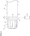
- a reference portion of the barrel body 12 and a reference portion of the cap 14 are photographed by a camera 59 as one image (still image) as illustrated in Fig. 5 .
- the reference portion of the barrel body 12 is the distal end of the lock adapter 22, while the reference portion of the cap 14 is the proximal end of the stopper 40 of the outer cap 36.
- a portion other than the distal end of the lock adapter 22 in the barrel body 12 may be set as a reference portion and a portion other than the proximal end of the stopper 40 in the outer cap 36 may be set as the reference portion.
- the determination step determines the barrel assembly as a non-defective product in a case where a distance W between the reference portion of the barrel body 12 and the reference portion of the cap 14 is a predetermined value or less (for example, 0.5 mm or less) in the image photographed by the camera 59.
- This determination is automatically made by a determination apparatus (computer) having an image processing function.
- the determination apparatus specifies the reference portion of the barrel body 12 and the reference portion of the cap 14 from the obtained image, for example using pattern matching, for example, and measures the distance between the reference portions. Then, the determination apparatus determines whether the barrel assembly is conforming or non-conforming on the basis of the obtained distance.
- the axial length L (refer to Fig. 3 ) of the compressed portion 52 described above is the predetermined value or more.
- the axial length L of the compressed portion 52 is shorter than the axial length of the cylindrical wall 44. This makes it possible to restrain difficulty in opening the cap 14 due to an increase in opening torque of the cap 14 (torque required for turning the cap 14 to open). From such a viewpoint, the axial length L of the compressed portion 52 is set to, for example, 5 mm or less, preferably 3 mm or less, and more preferably 2 mm or less. The axial length L of the compressed portion 52 may be the same as the axial length of the cylindrical wall 44 unless emphasis is placed on the opening torque of the cap 14.
- the compressed portion 52 is provided at the distal end portion of the cylindrical wall 44.
- This configuration forms a liquid tight seal at the distal end portion of the outer peripheral surface 20a of the nozzle portion 20, making it possible to further effectively prevent leakage of the drug solution M to the outside of the cap 14.
- the compressed portion 52 may be provided in the proximal side region of the cylindrical wall 44.
- the compressibility of the compressed portion 52 is in a range of, for example, 5% to 50%, preferably 10% to 20%.
- the compressibility of the compressed portion 52 represents a ratio of the amount of strain to the thickness of the compressed portion 52 in the natural state (state where the compressed portion 52 is not sandwiched between the nozzle portion 20 and the outer cap 36).
- the amount of strain is ⁇
- the thickness of the compressed portion 52 in the natural state is T0
- the thickness of the compressed portion 52 in the compressed state is T1
- ⁇ T0 - T1 holds.
- the syringe barrel 15 pre-filled syringe 10
- the cylindrical wall 44 of the inner cap 34 formed of an elastic material is compressed between the outer peripheral surface 20a of the nozzle portion 20 and the inner peripheral surface 37 of the outer cap 36.
- This configuration allows close contact between the outer peripheral surface 20a of the nozzle portion 20 and the inner peripheral surface 45 of the cylindrical wall 44, forming a liquid tight seal at a close contact portion. This restrains leakage of the drug solution M in the barrel body 12 to the outside of the cap 14.
- the axial length L of the compressed portion 52 is 0.5 mm or more, it is possible to appropriately increase the length of the liquid tight seal formed by the close contact between the cylindrical wall 44 and the nozzle portion 20.
- This configuration makes it possible to suitably prevent the leakage of the drug solution M to the outside of the cap 14. Furthermore, for it is possible to reliably prevent liquid leakage in a pre-filled syringe 10 determined to be a non-defective product in a case where a loosening length threshold for determining acceptance in the cap mounting inspection is 0.5 mm.
- the compressed portion 52 includes the enlarged diameter portion 54 protruding outward in the radial direction more than the other portion of the cylindrical wall 44, making it easier to increase the close contact area between the cylindrical wall 44 and the nozzle portion 20 (liquid tight seal area).
- the inner peripheral surface 45 of the cylindrical wall 44 has a shape substantially corresponding to the outer peripheral surface 20a of the nozzle portion 20. With this configuration, the axial length of the close contact portion between the cylindrical wall 44 and the nozzle portion 20 is longer than the axial length of the enlarged diameter portion 54, making it further easier to increase the close contact area between the cylindrical wall 44 and the nozzle portion 20 (liquid tight seal area).
- the shape substantially corresponding to the outer peripheral surface 20a of the nozzle portion 20 represents a shape that allows most of the inner peripheral surface 45 of the cylindrical wall 44 to be in contact with the outer peripheral surface 20a of the nozzle portion 20.
- the axial length L of the compressed portion 52 is shorter than the axial length of the cylindrical wall 44, making it possible to effectively restrain an increase in the opening torque of the cap 14 due to the presence of the compressed portion 52.
- the compressed portion 52 is provided at the distal end portion of the cylindrical wall 44, leading to formation of liquid tight seal at the distal end portion of the outer peripheral surface 20a of the nozzle portion 20. This makes is possible to further effectively prevent the liquid leakage to the outside of the cap 14.
- the present invention is particularly useful in that liquid leakage can be effectively prevented even when the diameter of the distal end opening 21 of the nozzle portion 20 is as relatively large as 1.5 mm or more. That is, with relatively large diameter of the distal end opening 21 of the nozzle portion 20, a large pressure is applied to the inner cap 34 even in a state where the cap 14 is tightly closed (state where the inner cap 34 and the distal end surface 20b of the nozzle portion 20 are in close contact with each other). Therefore, when the diameter of a distal end opening of a nozzle portion is relatively large (for example, when the diameter is 1.5 mm or more) with a conventional cap without the compressed portion 52, the liquid leakage is likely to occur. In contrast, according to the present invention, liquid leakage can be effectively prevented by the presence of the compressed portion 52 even when the diameter of the distal end opening 21 of the nozzle portion 20 is as relatively large as 1.5 mm or more.
- the compressed portion 52a may be formed by pressing the cylindrical wall 44 by an annular protrusion 60 provided on the inner peripheral surface 37 of the outer cap 36.
- the inner peripheral surface 37 of the outer cap 36 includes the annular protrusion 60 that protrudes inward in the radial direction and presses the cylindrical wall 44.
- the annular protrusion 60 presses the distal end portion of the cylindrical wall 44 inward in the radial direction.
- the compressed portion 52a is a portion of the cylindrical wall 44, sandwiched in a compressed state between the inner peripheral surface of the annular protrusion 60 and the outer peripheral surface 20a of the nozzle portion 20.
- the outer peripheral portion of the inner cap 34 illustrated in Fig. 6 includes an annular groove 62 recessed inward in the radial direction, and the annular protrusion 60 is engaged with the annular groove 62.
- This configuration inhibits a relative movement in the axial direction between the inner cap 34 and the outer cap 36.
- the annular protrusion 60 also serves as a means for inhibiting axial relative movement of the inner cap 34 and the outer cap 36, and a means for pressing the cylindrical wall 44 inward in the radial direction.
- a cap 14a of a pre-filled syringe 10a according to a second embodiment of the present invention illustrated in Fig. 7 includes: the inner cap 34 (same as the inner cap 34 illustrated in Fig. 2 or the like) for sealing the distal end opening 21; and a hollow cylindrical outer cap 36a for supporting the inner cap 34.
- the barrel body 12 and the cap 14a constitute a syringe barrel 15a.
- the outer cap 36a includes: a proximal end cylindrical portion 70 covering the cylindrical wall 44; and a distal end cylindrical portion 72 provided on more toward the distal side than the proximal end cylindrical portion 70 and covering the base portion 42 of the inner cap 34.
- the proximal end cylindrical portion 70 includes an engaging portion 74 engageable with the cylindrical wall 44 and provided on an inner peripheral surface 70a of the proximal end cylindrical portion 70.
- the cylindrical wall 44 of the inner cap 34 and the proximal end cylindrical portion 70 of the outer cap 36a are inserted into the annular groove 48, and the inner peripheral surface of the cylindrical wall 44 is in close contact with the outer peripheral surface 20a of the nozzle portion 20.
- the engaging portion 74 may be or need not be in contact with the cylindrical wall 44.
- the engaging portion 74 is an engaging protrusion 74a protruding inward in the radial direction from the inner peripheral surface 70a of the proximal end cylindrical portion 70 of the outer cap 36a.
- the engaging protrusions 74a extend in the circumferential direction and is provided in plurality at intervals in the circumferential direction.
- two engaging protrusions 74a are provided at positions facing each other on the inner peripheral surface 70a of the proximal end cylindrical portion 70.
- the cylindrical wall 44 includes an engaged portion 76 engageable with the engaging protrusion 74a.
- the engaged portion 76 is a proximal end surface 44a of the cylindrical wall 44.
- the inner peripheral surface 72a of the distal end cylindrical portion 72 of the outer cap 36a includes two arcuate protrusions 78 protruding from the inner peripheral surface 72a inward in the radial direction and engaging with the annular groove 48 of the inner cap 34 at intervals in the circumferential direction.
- the arcuate protrusion 78 is a protrusion extending in an arc shape in the circumferential direction and provided in place of the above-described annular protrusion 50 ( Fig. 3 ).
- the two engaging protrusions 74a and the two arcuate protrusions 78 are disposed 90° shifted with each other in the circumferential direction so as not to form an undercut at the time of injection molding.
- Pseudo fixation is a state where two members adhere to each other and a predetermined level of force or more is required to release the adhesion.
- the cylindrical wall 44 of the inner cap 34 expands and causes the cap 14a to be removed after full expansion of the cylindrical wall 44, leading to spouting out of the drug solution M from the inside of the barrel body 12.
- Spouting out of the drug solution M might decrease the liquid amount and cause the drug solution M to be attached to the surroundings.
- the engagement between the engaging portion 74 and the cylindrical wall 44 allows the moving force of the outer cap 36a in moving toward the lock adapter 22 to be transmitted directly to the cylindrical wall 44. That is, when the cylindrical wall 44 expands at the time of opening the cap 14a to move with the outer cap 36a alone, the engaging protrusion 74a of the outer cap 36a is caught on the inner cap 34.
- the engaging portion 74 is the engaging protrusion 74a protruding inward in the radial direction from the inner peripheral surface 70a of the proximal end cylindrical portion 70 of the outer cap 36a, and the cylindrical wall 44 includes the engaged portion 76 to be engaged with the engaging protrusion 74a.
- engagement of the engaging protrusion 74a with the engaged portion 76 from the proximal side allows the moving force to be transmitted directly to the cylindrical wall 44. This configuration enables acquisition of a further satisfactory engaging force, making it possible to further reliably move the inner cap 34 together with the movement of the outer cap 36a when the cap 14a is removed from the barrel body 12.
- the engaged portion 76 is the proximal end surface 44a of the cylindrical wall 44.
- the proximal end surface 44a of the cylindrical wall 44 is pressed in the distal direction by the engaging portion 74 when the cap 14a is removed from the barrel body 12, making it possible to move the entire cylindrical wall 44 integrally with the outer cap 36a.
- the proximal end surface 44a of the cylindrical wall 44 can be utilized as it is as the engaged portion 76, making it possible to avoid complication of the structure of the cylindrical wall 44 due to the presence of the engaged portion 76.
- the barrel body 12 is formed of a cyclic olefin polymer or a cyclic olefin copolymer.
- the inner cap 34 is likely to be pseudo fixed to the nozzle portion 20. Accordingly, the present invention capable of restraining expansion of the cylindrical wall 44 at the time of opening the cap 14a is particularly useful.
- the inner cap 34 formed from butyl rubber, the inner cap 34 is further likely to be pseudo fixed to the nozzle portion 20, making the present invention further useful.
- Sterilization treatment for example, high pressure steam sterilization
- a thermal load onto the syringe barrel 15a has been applied on the syringe barrel 15a in the mounted state.
- sterilization treatment involving a thermal load
- the inner cap 34 is further likely to be pseudo fixed to the nozzle portion 20. Accordingly, the present invention capable of restraining expansion of the cylindrical wall 44 at the time of opening the cap 14a is particularly useful.
- a cap 14b of a pre-filled syringe 10b according to a third embodiment of the present invention illustrated in Fig. 9 includes: the inner cap 34 (same as the inner cap 34 illustrated in Fig. 2 or the like) for sealing the distal end opening 21; and a hollow cylindrical outer cap 36b for supporting the inner cap 34.
- the barrel body 12 and the cap 14b constitute a syringe barrel 15b.
- the proximal end cylindrical portion 70 of the outer cap 36b includes an engaging portion 80 engageable with the cylindrical wall 44 and provided on the inner peripheral surface 70a of the proximal end cylindrical portion 70.
- the engaging portion 80 is an engaging protrusion 80a protruding inward in the radial direction from the inner peripheral surface 70a of the proximal end cylindrical portion 70 of the outer cap 36a.
- the engaging protrusion 80a is an annular protrusion extending over the entire circumference in the circumferential direction.
- the cylindrical wall 44 includes an engaged portion 82 engageable with the engaging protrusion 80a.
- the engaged portion 82 is an engaged protrusion 82a protruding outward in the radial direction from the outer peripheral surface of the cylindrical wall 44 and is provided on more toward the distal side than the engaging protrusion 74a.
- the enlarged diameter portion 54 constitutes the engaged protrusion 82a.
- the engaged protrusion 82a may be provided on more proximal side than the enlarged diameter portion 54, separately from the enlarged diameter portion 54.
- the engaging portion 80 is provided on more toward the proximal side than the position illustrated in Fig. 9 .
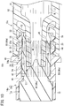
- a cap 14c of a pre-filled syringe 10c according to a fourth embodiment of the present invention illustrated in Fig. 10 includes: the inner cap 34 (same as the inner cap 34 illustrated in Fig. 2 or the like) for sealing the distal end opening 21; and a hollow cylindrical outer cap 36c for supporting the inner cap 34.
- the barrel body 12 and the cap 14c constitute a syringe barrel 15c.
- the proximal end cylindrical portion 70 of the outer cap 36c includes an engaging portion 86 engageable with the cylindrical wall 44 and provided on the inner peripheral surface 70a of the proximal end cylindrical portion 70.
- the engaging portion 86 is a plurality of engaging ribs 86a extending along the axis of the proximal end cylindrical portion 70. As illustrated in Fig. 11 , the plurality of engaging ribs 86a is arranged at intervals in the circumferential direction.
- the cylindrical wall 44 includes an engaged portion 90 engaged with the plurality of engaging ribs 86a, on the outer peripheral surface of the cylindrical wall 44.
- the plurality of engaging ribs 86a bites into the engaged portion 90.
- the enlarged diameter portion 54 constitutes the engaged portion 90.
- the engaged portion 90 may be provided on more proximal side than the enlarged diameter portion 54, separately from the enlarged diameter portion 54.
- An engaged rib meshed with the engaged rib 86a may be provided on the outer peripheral surface of the cylindrical wall 44. In this case, the engaged rib extends along the axis of the cylindrical wall 44 and is provided in plurality at intervals in the circumferential direction.
Landscapes
- Health & Medical Sciences (AREA)
- Heart & Thoracic Surgery (AREA)
- Hematology (AREA)
- Engineering & Computer Science (AREA)
- Anesthesiology (AREA)
- Biomedical Technology (AREA)
- Life Sciences & Earth Sciences (AREA)
- Animal Behavior & Ethology (AREA)
- General Health & Medical Sciences (AREA)
- Public Health (AREA)
- Veterinary Medicine (AREA)
- Vascular Medicine (AREA)
- Pulmonology (AREA)
- Infusion, Injection, And Reservoir Apparatuses (AREA)
Abstract
Description
- The present invention relates to a syringe barrel, a syringe barrel manufacturing method, and a pre-filled syringe.
- In a conventional pre-filled syringe filled with a liquid beforehand, a cap to close a nozzle portion liquid tight is mounted to a distal end of a barrel in order to prevent leakage of a liquid inside the syringe from a syringe distal end opening prior to use of the syringe, particularly during transportation (refer to, for example,
JP 2736245 B2 - The cap disclosed in
JP 2736245 B2 - In the case of the cap disclosed in
JP 2736245 B2 - The present invention has been made in consideration of such problems, and aims to provide a syringe barrel, a syringe barrel manufacturing method, and a pre-filled syringe, capable of preventing leakage of a liquid to the outside of a cap even in a case where the cap slightly moves in the distal direction with respect to a barrel body.
- To achieve the above object, a syringe barrel of the present invention includes: a barrel body including a nozzle portion at a distal end thereof, a cap removably mounted to the nozzle portion and configured to seal a distal end opening of the nozzle portion, in which the cap comprising: an inner cap formed of an elastic material and configured to be in liquid tight close contact with the nozzle portion in a mounted state in which the cap is mounted to the nozzle portion; and a cylindrical outer cap formed of a material having higher hardness than the inner cap and fixed around the inner cap, the inner cap comprises: a base portion; and a cylindrical wall extending from the base portion in a proximal direction and surrounding the nozzle portion, the cylindrical wall is configured to be sandwiched in a compressed state between an outer peripheral surface of the nozzle portion and an inner peripheral surface of the outer cap in a state in which the base portion is in close contact with a distal end surface of the nozzle portion and in a state in which the base portion is apart from the distal end surface of the nozzle portion by a predetermined distance, such that the cylindrical wall is in liquid tight close contact over a full circumference with the outer peripheral surface of the nozzle portion.
- According to the syringe barrel of the present invention having the above configuration, the cylindrical wall of the inner cap formed of an elastic material is compressed between the outer peripheral surface of the nozzle portion and the inner peripheral surface of the outer cap even in a case where the cap slightly moves in the distal direction from the state of close contact with the distal end surface of the nozzle portion. This configuration allows close contact between the outer peripheral surface of the nozzle portion and the inner peripheral surface of the cylindrical wall, forming a liquid tight seal at a close contact portion. Accordingly, it is possible to effectively prevent leakage of the liquid in the barrel body to the outside of the cap.
- In the syringe barrel described above, an axial length of a compressed portion, which a portion of the cylindrical wall compressed between the nozzle portion and the outer cap in a state in which the base portion is in close contact with the distal end surface of the nozzle portion, may be 0.5 mm or more.
- This configuration appropriately increases a length of a liquid tight seal due to the close contact between the cylindrical wall and the nozzle portion, making it possible to suitably prevent leakage of a drug solution to the outside of the cap. Furthermore, for example, it is possible to reliably prevent liquid leakage in a pre-filled syringe determined to be a non-defective product in a case where a loosening length threshold for determining acceptance in the cap mounting inspection is 0.5 mm.
- In the syringe barrel described above, the compressed portion may include an enlarged diameter portion protruding outward in a radial direction more than the other portions of the cylindrical wall.
- This configuration can easily increase a close contact area (liquid tight seal area) between the cylindrical wall and the nozzle portion.
- In the syringe barrel described above, the inner peripheral surface of the cylindrical wall may have a shape substantially corresponding to the outer peripheral surface of the nozzle portion.
- With this configuration, the axial length of the close contact portion between the cylindrical wall and the nozzle portion is longer than the axial length of the enlarged diameter portion, making it easier to increase the close contact area between the cylindrical wall and the nozzle portion (liquid tight seal area).
- In the syringe barrel described above, the axial length of the compressed portion may be shorter than the axial length of the cylindrical wall.
- With this configuration, it is possible to effectively restrain an increase in a cap opening torque (torque needed to turn the cap for opening the cap) due to the presence of the compressed portion.
- In the syringe barrel described above, the compressed portion may be disposed at a distal end portion of the cylindrical wall.
- This configuration forms a liquid tight seal at the distal end portion of the outer peripheral surface of the nozzle portion, making it possible to further effectively prevent liquid leakage to the outside of the cap.
- In the syringe barrel described above, a compressibility of the compressed portion, which a portion of the cylindrical wall compressed between the nozzle portion and the outer cap in the mounted state, may be in a range of 5% to 50%.
- With this configuration, it is possible to effectively prevent an excessive increase in the opening torque of the cap while holding satisfactory pressure resistance.
- In the syringe barrel described above, a diameter of the distal end opening of the nozzle portion may be 1.5 mm or more.
- With a relatively large diameter of the distal end opening of the nozzle portion, a large pressure would be applied to the inner cap even in a state where the cap is tightly closed (state where the inner cap and the distal end surface of the nozzle portion are in close contact with each other), leading to a high probability of liquid leakage in the absence of the compressed portion. The present invention is particularly useful in that liquid leakage can be effectively prevented by the presence of the compressed portion even in a case where the diameter of the distal end opening of the nozzle portion is as relatively large as 1.5 mm or more.
- It is allowable to have a configuration in which the barrel body includes: a lock adapter disposed on an outer side of the nozzle portion; and an annular recess disposed between the nozzle portion and the lock adapter and recessed in a proximal direction, the outer cap includes a proximal end cylindrical portion covering the cylindrical wall, the proximal end cylindrical portion of the outer cap includes an engaging portion on an inner peripheral surface of the proximal end cylindrical portion, the engaging portion being configured to engage with the cylindrical wall, wherein, in the mounted state, the cylindrical wall of the inner cap and the proximal end cylindrical portion of the outer cap are inserted into the annular recess, and the inner peripheral surface of the cylindrical wall is in close contact with the outer peripheral surface of the nozzle portion, and when the cap in the mounted state is removed from the barrel body, engagement between the engaging portion and the cylindrical wall allows a moving force of the outer cap to move with respect to the lock adapter to be transmitted directly to the cylindrical wall.
- According to this configuration, it is possible to move the inner cap together with the movement of the outer cap at removal of the cap from the barrel body even in a case where the inner peripheral surface of the cylindrical wall of the inner cap is pseudo fixed (adhered) to the outer peripheral surface of the nozzle portion, making it possible to restrain expansion of the cylindrical wall. This makes is possible to prevent the drug solution from spouting out at the time of opening the cap.
- It is allowable to have a configuration in which the engaging portion is an engaging protrusion that protrudes inward in a radial direction from the inner peripheral surface of the proximal end cylindrical portion of the outer cap, and the cylindrical wall includes a engaged portion that is configured to be engaged with the engaging protrusion, and when the cap in the mounted state is removed from the barrel body, engagement of the engaging protrusion with the engaged portion from a proximal end thereof allows the moving force to be transmitted directly to the cylindrical wall.
- This configuration enables acquisition of a further satisfactory engaging force, making it possible to further reliably move the inner cap together with the movement of the outer cap when the cap is removed from the barrel body.
- The engaged portion may be a proximal end surface of the cylindrical wall.
- With this configuration, the proximal end surface of the cylindrical wall is pressed in the distal direction by the engaging portion when the cap is removed from the barrel body, making it possible to move the entire cylindrical wall integrally with the outer cap. In addition, the proximal end surface of the cylindrical wall can be utilized as it is as the engaged portion, making it possible to avoid structural complication of the cylindrical wall due to the presence of the engaged portion.
- The engaged portion may be an engaged protrusion that protrudes outward in the radial direction from the outer peripheral surface of the cylindrical wall.
- This configuration enables acquisition of a further satisfactory engaging force, making it possible to further reliably move the inner cap together with the movement of the outer cap when the cap is removed from the barrel body.
- It is allowable to have a configuration in which the lock adapter includes a female screw portion on an inner peripheral surface of the lock adapter, the outer cap includes a male screw portion that is disposed on the outer peripheral surface of the proximal end cylindrical portion, the male screw portion being configured to be screwed together with the female screw portion, the female screw portion and the male screw portion are screwed with each other in the mounted state, the engaging portion is a plurality of engaging ribs extending along an axis of the proximal end cylindrical portion, the cylindrical wall includes a engaged portion that is disposed on the outer peripheral surface of the cylindrical wall, the engaged portion being configured to be engaged with the plurality of engaging ribs, and when the outer cap is rotated with respect to the lock adapter to remove the cap in the mounted state from the barrel body, engagement between the plurality of engaging ribs and the engaged portion allows the moving force of the outer cap to rotationally move with respect to the lock adapter to be transmitted directly to the cylindrical wall.
- This configuration causes the cylindrical wall of the inner cap to rotate simultaneously with the outer cap when the cap is removed from the barrel body, making it possible to further reliably move the inner cap together with the movement of the outer cap.
- The barrel body may be formed of a cyclic olefin polymer or a cyclic olefin copolymer.
- With the barrel body formed of a cyclic olefin polymer or a cyclic olefin copolymer, the inner cap is likely to be pseudo fixed to the nozzle portion. Accordingly, the present invention is capable of restraining expansion of the cylindrical wall at the time of opening the cap is particularly useful.
- The inner cap may be formed from butyl rubber.
- With the barrel body formed from butyl rubber, the inner cap is further likely to be pseudo fixed to the nozzle portion. Accordingly, the present invention is capable of restraining expansion of the cylindrical wall at the time of opening the cap is particularly useful.
- Sterilization treatment involving a thermal load onto the syringe barrel may be applied on the syringe barrel in the mounted state.
- With application of sterilization treatment involving a thermal load, the inner cap is further likely to be pseudo fixed to the nozzle portion. Accordingly, the present invention is capable of restraining expansion of the cylindrical wall at the time of opening the cap is particularly useful.
- Furthermore, the pre-filled syringe of the present invention includes: any one of the syringe barrels described above; a gasket slidably inserted in the barrel body; a plunger coupled or couplable to the gasket, and a drug solution filled in a liquid chamber formed by the barrel body and the gasket.
- A syringe barrel manufacturing method according to the present invention including: an assembling step of mounting the cap to the barrel body to assemble a barrel assembly; a photographing step of photographing a reference portion of the barrel body and a reference portion of the cap as one image using a camera; and a determination step of determining that the barrel assembly is a non-defective product if a distance between the reference portion of the barrel body and the reference portion of the cap is a predetermined value or less in the image photographed by the camera, in which an axial length of a compressed portion, which is a portion of the cylindrical wall compressed between the nozzle portion and the outer cap in a state in which the base portion is in close contact with the distal end surface of the nozzle portion, is the predetermined value or more.
- With the syringe barrel and the syringe barrel manufacturing method, and the pre-filled syringe of the present invention, it is possible to prevent the leakage of a liquid to the outside of the cap even in a case where the cap slightly moves in the distal direction with respect to the barrel body.
-
-
Fig. 1 is a perspective view of a pre-filled syringe according to a first embodiment of the present invention. -
Fig. 2 is an exploded perspective view of a distal end portion of the pre-filled syringe illustrated inFig. 1 . -
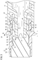
Fig. 3 is a cross sectional view of a distal end portion of the pre-filled syringe illustrated inFig. 1 . -
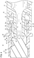
Fig. 4 is a cross sectional view illustrating a state where a cap has slightly moved in a distal direction from the state ofFig. 3 with respect to a nozzle portion. -
Fig. 5 is a diagram illustrating a photographing step in a syringe barrel manufacturing method. -
Fig. 6 is a cross sectional view of a distal end portion of a pre-filled syringe according to a modification. -
Fig. 7 is a cross sectional view of a distal end portion of a pre-filled syringe according to a second embodiment of the present invention. -
Fig. 8 is a cross sectional view of the distal end portion of the pre-filled syringe according to the second embodiment of the present invention, taken at an angle different from that inFig. 7 . -
Fig. 9 is a cross sectional view of a distal end portion of a pre-filled syringe according to a third embodiment of the present invention. -
Fig. 10 is a cross sectional view of a distal end portion of a pre-filled syringe according to a fourth embodiment of the present invention. -
Fig. 11 is a perspective view of an outer cap of the pre-filled syringe illustrated inFig. 10 . - Preferred embodiments of a syringe barrel, a syringe barrel manufacturing method, and a pre-filled syringe according to the present invention will be described below with reference to the accompanying drawings.
- A
pre-filled syringe 10 according to a first embodiment illustrated inFig. 1 includes, as main components: abarrel body 12 formed of a hollow body provided with anozzle portion 20; acap 14 for sealing thenozzle portion 20 of thebarrel body 12; agasket 16 slidably inserted in thebarrel body 12; and a drug solution M filled in aliquid chamber 17 formed by thebarrel body 12 and thegasket 16. Thebarrel body 12 and thecap 14 constitute asyringe barrel 15. - The
barrel body 12 includes: abody portion 18 having a substantially cylindrical shape and including a proximal end opening 19 formed at a proximal end; a nozzle portion 20 (refer toFig. 2 ) provided at a distal end of thebarrel portion 18; alock adapter 22 provided on an outer side of thenozzle portion 20; and aflange 24 protruding outward in a radial direction from the distal end of thebody portion 18. In thebarrel body 12 in the illustrated example, thebody portion 18, thenozzle portion 20, thelock adapter 22, and theflange 24 are integrally formed. - The
gasket 16 is inserted through thebarrel body 12 via theproximal end opening 19. The proximal side of thebarrel body 12 is sealed liquid tight with thegasket 16, and the drug solution M is sealed within thebarrel body 12. - The
gasket 16 is formed of an elastic material such as a rubber material. Thegasket 16 allows its outer peripheral portion to be in liquid tight contact with the inner peripheral surface of thebarrel body 12, and is slidably disposed in thebarrel body 12. Thegasket 16 is coupled with a distal end portion of theplunger 26. Operation of pressing theplunger 26 in the distal direction performed by the user causes thegasket 16 to slide in the distal direction inside thebarrel body 12. Note that theplunger 26 may be coupled to thegasket 16 at the time of administration of the drug solution M to a patient. - As illustrated in
Fig. 2 , thenozzle portion 20 is diametrically reduced from the center on the distal end of thebarrel body 12 with respect to thebarrel body 12 and extends in the distal direction. Thenozzle portion 20 includes a tapered outerperipheral surface 20a having outer diameter reducing toward the distal direction. That is, the outerperipheral surface 20a of thenozzle portion 20 constitutes a Luer taper. As illustrated inFig. 3 , thenozzle portion 20 includes aliquid path 28 communicating with theliquid chamber 17 in thebarrel body 12 and penetrating in the axial direction. The distal end of theliquid path 28 forms a distal end opening 21 of thenozzle portion 20. - In a state where the
cap 14 is removed from thenozzle portion 20, a needle unit (not illustrated) detachably provided on thenozzle portion 20. The needle unit includes: a needle body having a needle point; and a needle hub having a protrusion fixed to the proximal end portion of the needle body and protruding outward. Thenozzle portion 20 can be taper-fitted to an inner peripheral portion of the needle hub. In use of thepre-filled syringe 10, thecap 14 is unplugged (removed from thebarrel 20 and the lock adapter 22), and instead the needle hub of the needle unit is connected to thenozzle portion 20 and thelock adapter 22. - The
lock adapter 22 in the illustrated example is formed in a substantially hollow circular shape extending in the distal direction from the distal end of thebody portion 18 and surrounding thenozzle portion 20. The above-describednozzle portion 20 protrudes more toward the distal direction than thelock adapter 22, forming anannular recess 30 recessed in the proximal direction between thelock adapter 22 and thenozzle portion 20. The inner peripheral surface of thelock adapter 22 includes afemale screw portion 32. Thefemale screw portion 32 is removably engaged with a male screw portion 38 (described below) of thecap 14. In a state where thecap 14 is removed from thebarrel body 12, thefemale screw portion 32 is engageable with a protrusion provided on the needle hub of the above-described needle unit. - While the
lock adapter 22 of the illustrated example is integrally formed at the distal end portion of thebody portion 18 as a portion of thebarrel body 12, thelock adapter 22 may be integrally formed at the proximal end portion of thenozzle portion 20. Alternatively, thelock adapter 22 may be configured as a separate component from thebody portion 18 and thenozzle portion 20, and may be a member fixed to thebarrel body 12 or thenozzle portion 20. - Examples of the constituent material of the
barrel body 12 include various resins such as polypropylene, polyethylene, polystyrene, polyamide, polycarbonate, polyvinyl chloride, poly- (4-methylpentene-1), acrylic resin, acrylonitrile-butadiene-styrene copolymer, polyester such as polyethylene terephthalate, and cyclic olefin polymer. - The
cap 14 is removably mounted to thenozzle portion 20, and seals the distal end opening 21 of thenozzle portion 20. The illustratedcap 14 is detachably provided on thenozzle portion 20. As illustrated inFigs. 2 to 4 , thecap 14 includes: aninner cap 34 for sealing thedistal end opening 21; and a hollow cylindricalouter cap 36 for supporting theinner cap 34. - The
inner cap 34 is formed of an elastic material. In a state before use (hereinafter also referred to as "mounted state") where thecap 14 is mounted to thenozzle portion 20, theinner cap 34 is in liquid tight close contact with thenozzle portion 20 so as to restrain leakage of the drug solution M to the outside of thecap 14. InFig. 3 , theinner cap 34 is in close contact over a full circumference with each of the outerperipheral surface 20a and thedistal end surface 20b of thenozzle portion 20. - Examples of the elastic material of the
inner cap 34 include various rubber materials such as natural rubber, butyl rubber, isoprene rubber, butadiene rubber, styrenebutadiene rubber, and silicone rubber, or various types of thermoplastic elastomer such as polyurethane type, polyester type, polyamide type, olefin type, and styrene type, or a mixture of these. - As illustrated in
Figs. 3 and4 , theouter cap 36 is fixed to the outer periphery of theinner cap 34. Themale screw portion 38 to be releasably screwed to thefemale screw portion 32 of thelock adapter 22 is formed on the proximal end outer peripheral portion of theouter cap 36. On more toward the distal side than themale screw portion 38 on the outer peripheral portion of theouter cap 36, there is provided astopper 40 protruding outward in the radial direction. - In a state where the
cap 14 is firmly (completely) mounted to thenozzle portion 20 and thelock adapter 22, theouter cap 36 is screwed to thelock adapter 22 up to a position where the proximal end surface of thestopper 40 and the distal end surface of thelock adapter 22 are in contact with each other. Accordingly, in the process of assembling thesyringe barrel 15, checking the presence or absence and the size of a gap between thestopper 40 and thelock adapter 22 leads to checking whether thecap 14 is satisfactorily mounted to thebarrel body 12. While thestopper 40 in the illustrated example is formed in an annular shape over a full circumference in the circumferential direction of theouter cap 36, it is allowable to provide a plurality of thestoppers 40 at intervals in the circumferential direction. - Next, a configuration of the
inner cap 34 will be described in more detail. Theinner cap 34 includes abase portion 42 located on more toward the distal side than thenozzle portion 20 in the mounted state; and acylindrical wall 44 extending from thebase portion 42 in the proximal direction. Thebase portion 42 and thecylindrical wall 44 forms arecess 46 recessed in the distal direction. Thebase portion 42 constitutes a distal side portion of theinner cap 34. - The outer peripheral portion of the
base portion 42 includes anannular groove 48 recessed inward in the radial direction, and anannular protrusion 50 provided on the inner peripheral portion of theouter cap 36 is engaged with theannular groove 48. This configuration inhibits a relative movement in the axial direction between theinner cap 34 and theouter cap 36. InFig. 3 , the proximal end surface 43 (the bottom portion of the recess 46) of thebase portion 42 is brought into close contact over a full circumference with thedistal end surface 20b of thenozzle portion 20 and slightly squeezed in the distal direction by thedistal end surface 20b. - The
cylindrical wall 44 is formed in a hollow cylindrical shape. In the mounted state of thecap 14, thecylindrical wall 44 surrounds thenozzle portion 20. Moreover, thecylindrical wall 44 is sandwiched in a compressed state between the outerperipheral surface 20a of thenozzle portion 20 and the innerperipheral surface 37 of theouter cap 36 in a state where thebase portion 42 is in close contact with thedistal end surface 20b of the nozzle portion 20 (Fig. 3 ) and in a state where thebase portion 42 is apart from thedistal end surface 20b of thenozzle portion 20 by a predetermined distance (Fig. 4 ). - This brings the inner
peripheral surface 45 of thecylindrical wall 44 into close contact over a full circumference with the outerperipheral surface 20a of thenozzle portion 20, so as to form a liquid tight seal at this close contact portion in the state illustrated inFigs. 3 and4 . This restrains leakage of the drug solution M to the outside of thecap 14 even in a case where thecap 14 slightly moves in the distal direction from the state ofFig. 3 and where theproximal end surface 43 of thebase portion 42 is apart from thedistal end surface 20b of thenozzle portion 20 as illustrated inFig. 4 . - Specifically, the
cylindrical wall 44 includes a compressedportion 52 compressed in the radial direction (wall thickness direction of the cylindrical wall 44) between the outerperipheral surface 20a of thenozzle portion 20 and the innerperipheral surface 37 of theouter cap 36. Accordingly, the inner peripheral surface of the compressedportion 52 and the outerperipheral surface 20a of thenozzle portion 20 are in close contact over a full circumference with each other. In the present embodiment, the compressedportion 52 includes an enlarged diameter portion 54 (refer to alsoFig. 2 ) protruding outward in the radial direction rather than the other portion of thecylindrical wall 44, and is sandwiched between thenozzle portion 20 and the innerperipheral surface 37 of theouter cap 36, so as to form a high-intensity close contact portion a having higher degree of contact than other portions. - An outer
peripheral surface 54a of theenlarged diameter portion 54 has a constant outer diameter along the axial direction and is in close contact with the inner peripheral surface of theouter cap 36 over the entire axial length. The outer peripheral portion of thecylindrical wall 44 includes: a distal side taperedportion 56 continuing to the distal end of theenlarged diameter portion 54 and decreasing an outer diameter toward the distal direction; and a proximal side taperedportion 58 continuing to the proximal end of theenlarged diameter portion 54 and decreasing an outer diameter in the proximal direction. Note that the compressedportion 52 is only required to be sandwiched between thenozzle portion 20 and the innerperipheral surface 37 of theouter cap 36 so as to be able to form a high-intensity close contact portion having a higher degree of contact than other portions. Therefore, the compressedportion 52 may include, instead of theenlarged diameter portion 54, a reduced diameter portion protruding inward in a radial direction more than the other portions of thecylindrical wall 44 and provided on the inner peripheral portion of thecylindrical wall 44. - An axial length L (length from the distal end to the proximal end of the outer
peripheral surface 54a in close contact with the innerperipheral surface 37 of the outer cap 36) of the compressed portion 52 (enlarged diameter portion 54 or the reduced diameter portion) is 0.5 mm or more, for example, and preferably 1.0 mm or more. With the axial length L of the compressedportion 52 set within the above range, it is possible to appropriately increase the length of the liquid tight seal (close contact region between thecompressed portion 52 and the outerperipheral surface 20a), making it possible to suitably prevent leakage of the drug solution M to the outside of thecap 14. In the present embodiment, the axial length L is 0.5 mm or more. - In an assembling step of the
syringe barrel 15, a cap mounting inspection may be performed to determine whether thecap 14 is satisfactorily mounted to thebarrel body 12. This inspection defines a state (Fig. 3 ) in which thecap 14 is firmly mounted as a reference and makes determination of a non-defective product in a case where thecap 14 is loose at a predetermined length (for example, 0.5 mm) or less in the distal direction with respect to the reference, or makes determination of a non-non-defective product in a case where the cap is loose beyond the predetermined length. With the axial length L of the compressedportion 52 set to be longer than the loosening length determined to be non-conforming, it is possible to reliably prevent liquid leakage in thepre-filled syringe 10 using thesyringe barrel 15 determined to be conforming. - Specifically, the manufacturing method of the
syringe barrel 15 including such a cap mounting inspection includes an assembling step, a photographing step, and a determination step as follows. - In the assembling step, the
cap 14 is mounted to thebarrel body 12 to assemble the barrel assembly (syringe barrel 15). - After completion of the assembling step, next, the photographing step is performed. In the photographing step, a reference portion of the
barrel body 12 and a reference portion of thecap 14 are photographed by acamera 59 as one image (still image) as illustrated inFig. 5 . InFig. 5 , the reference portion of thebarrel body 12 is the distal end of thelock adapter 22, while the reference portion of thecap 14 is the proximal end of thestopper 40 of theouter cap 36. A portion other than the distal end of thelock adapter 22 in thebarrel body 12 may be set as a reference portion and a portion other than the proximal end of thestopper 40 in theouter cap 36 may be set as the reference portion. - After completion of the photographing step, a determination step is performed. The determination step determines the barrel assembly as a non-defective product in a case where a distance W between the reference portion of the
barrel body 12 and the reference portion of thecap 14 is a predetermined value or less (for example, 0.5 mm or less) in the image photographed by thecamera 59. This determination is automatically made by a determination apparatus (computer) having an image processing function. The determination apparatus specifies the reference portion of thebarrel body 12 and the reference portion of thecap 14 from the obtained image, for example using pattern matching, for example, and measures the distance between the reference portions. Then, the determination apparatus determines whether the barrel assembly is conforming or non-conforming on the basis of the obtained distance. The axial length L (refer toFig. 3 ) of the compressedportion 52 described above is the predetermined value or more. - In the present embodiment, the axial length L of the compressed
portion 52 is shorter than the axial length of thecylindrical wall 44. This makes it possible to restrain difficulty in opening thecap 14 due to an increase in opening torque of the cap 14 (torque required for turning thecap 14 to open). From such a viewpoint, the axial length L of the compressedportion 52 is set to, for example, 5 mm or less, preferably 3 mm or less, and more preferably 2 mm or less. The axial length L of the compressedportion 52 may be the same as the axial length of thecylindrical wall 44 unless emphasis is placed on the opening torque of thecap 14. - Furthermore, in the present embodiment, the compressed
portion 52 is provided at the distal end portion of thecylindrical wall 44. This configuration forms a liquid tight seal at the distal end portion of the outerperipheral surface 20a of thenozzle portion 20, making it possible to further effectively prevent leakage of the drug solution M to the outside of thecap 14. The compressedportion 52 may be provided in the proximal side region of thecylindrical wall 44. - In the mounted state of the
cap 14, the compressibility of the compressedportion 52 is in a range of, for example, 5% to 50%, preferably 10% to 20%. Here, the compressibility of the compressedportion 52 represents a ratio of the amount of strain to the thickness of the compressedportion 52 in the natural state (state where the compressedportion 52 is not sandwiched between thenozzle portion 20 and the outer cap 36). When the amount of strain is δ, the thickness of the compressedportion 52 in the natural state is T0, and the thickness of the compressedportion 52 in the compressed state is T1, δ = T0 - T1 holds. - With the compressibility of less than 5%, the degree of contact between the
cylindrical wall 44 and thenozzle portion 20 might become weak, leading to a failure in obtaining desired pressure resistance performance. On the other hand, the compressibility exceeding 50% might excessively increase the opening torque of thecap 14, making it difficult to open thecap 14. With setting of the compressibility in a range of 5% to 50%, it is possible to effectively prevent the cap opening torque of thecap 14 from becoming excessively large while maintaining satisfactory pressure resistance performance. - As described above, according to the syringe barrel 15 (pre-filled syringe 10), it is possible to effectively prevent leakage of the drug solution M even in a case where the
cap 14 slightly has moved in the distal direction from the state where thecap 14 is in close contact with thedistal end surface 20b of thenozzle portion 20 and where theproximal end surface 43 of thebase portion 42 of theinner cap 34 is slightly apart from thedistal end surface 20b of thenozzle portion 20. That is, even in a case where theproximal end surface 43 of thebase portion 42 of theinner cap 34 is slightly apart from thedistal end surface 20b of thenozzle portion 20 as illustrated inFig. 4 , thecylindrical wall 44 of theinner cap 34 formed of an elastic material is compressed between the outerperipheral surface 20a of thenozzle portion 20 and the innerperipheral surface 37 of theouter cap 36. This configuration allows close contact between the outerperipheral surface 20a of thenozzle portion 20 and the innerperipheral surface 45 of thecylindrical wall 44, forming a liquid tight seal at a close contact portion. This restrains leakage of the drug solution M in thebarrel body 12 to the outside of thecap 14. - In the present embodiment, since the axial length L of the compressed
portion 52 is 0.5 mm or more, it is possible to appropriately increase the length of the liquid tight seal formed by the close contact between thecylindrical wall 44 and thenozzle portion 20. This configuration makes it possible to suitably prevent the leakage of the drug solution M to the outside of thecap 14. Furthermore, for it is possible to reliably prevent liquid leakage in apre-filled syringe 10 determined to be a non-defective product in a case where a loosening length threshold for determining acceptance in the cap mounting inspection is 0.5 mm. - In the present embodiment, the compressed
portion 52 includes theenlarged diameter portion 54 protruding outward in the radial direction more than the other portion of thecylindrical wall 44, making it easier to increase the close contact area between thecylindrical wall 44 and the nozzle portion 20 (liquid tight seal area). In addition, the innerperipheral surface 45 of thecylindrical wall 44 has a shape substantially corresponding to the outerperipheral surface 20a of thenozzle portion 20. With this configuration, the axial length of the close contact portion between thecylindrical wall 44 and thenozzle portion 20 is longer than the axial length of theenlarged diameter portion 54, making it further easier to increase the close contact area between thecylindrical wall 44 and the nozzle portion 20 (liquid tight seal area). The shape substantially corresponding to the outerperipheral surface 20a of thenozzle portion 20 represents a shape that allows most of the innerperipheral surface 45 of thecylindrical wall 44 to be in contact with the outerperipheral surface 20a of thenozzle portion 20. - In the present embodiment, the axial length L of the compressed
portion 52 is shorter than the axial length of thecylindrical wall 44, making it possible to effectively restrain an increase in the opening torque of thecap 14 due to the presence of the compressedportion 52. - In the present embodiment, the compressed
portion 52 is provided at the distal end portion of thecylindrical wall 44, leading to formation of liquid tight seal at the distal end portion of the outerperipheral surface 20a of thenozzle portion 20. This makes is possible to further effectively prevent the liquid leakage to the outside of thecap 14. - With the compressibility of the compressed
portion 52 in a range of 5% to 50% in the present embodiment, it is possible to effectively prevent the cap opening torque of thecap 14 from becoming excessively large while maintaining satisfactory pressure resistance performance. - The present invention is particularly useful in that liquid leakage can be effectively prevented even when the diameter of the distal end opening 21 of the
nozzle portion 20 is as relatively large as 1.5 mm or more. That is, with relatively large diameter of the distal end opening 21 of thenozzle portion 20, a large pressure is applied to theinner cap 34 even in a state where thecap 14 is tightly closed (state where theinner cap 34 and thedistal end surface 20b of thenozzle portion 20 are in close contact with each other). Therefore, when the diameter of a distal end opening of a nozzle portion is relatively large (for example, when the diameter is 1.5 mm or more) with a conventional cap without the compressedportion 52, the liquid leakage is likely to occur. In contrast, according to the present invention, liquid leakage can be effectively prevented by the presence of the compressedportion 52 even when the diameter of the distal end opening 21 of thenozzle portion 20 is as relatively large as 1.5 mm or more. - While the above embodiment is an example in which the
enlarged diameter portion 54 is provided on the outer peripheral surface of thecylindrical wall 44, or the reduced diameter portion is provided on the inner peripheral surface of thecylindrical wall 44, whereby the compressedportion 52 compressed in the radial direction is formed between the outerperipheral surface 20a of thenozzle portion 20 and the innerperipheral surface 37 of theouter cap 36. Alternatively, as illustrated inFig. 6 , thecompressed portion 52a may be formed by pressing thecylindrical wall 44 by anannular protrusion 60 provided on the innerperipheral surface 37 of theouter cap 36. - Specifically, in
Fig. 6 , the innerperipheral surface 37 of theouter cap 36 includes theannular protrusion 60 that protrudes inward in the radial direction and presses thecylindrical wall 44. Theannular protrusion 60 presses the distal end portion of thecylindrical wall 44 inward in the radial direction. Thecompressed portion 52a is a portion of thecylindrical wall 44, sandwiched in a compressed state between the inner peripheral surface of theannular protrusion 60 and the outerperipheral surface 20a of thenozzle portion 20. - In a state illustrated in
Fig. 6 (state where theproximal end surface 43 of thebase portion 42 is in close contact with thedistal end surface 20b of the nozzle portion 20) and a state where thebase portion 42 is apart from thedistal end surface 20b of thenozzle portion 20 by a predetermined distance (state similar toFig. 4 ), the inner peripheral surface of thecompressed portion 52a is in close contact over a full circumference with the outerperipheral surface 20a of thenozzle portion 20, and a liquid tight seal is formed at this close contact portion. This restrains leakage of the drug solution M to the outside of thecap 14 even in a case where thecap 14 slightly moves in the distal direction from the state ofFig. 6 and where theproximal end surface 43 of thebase portion 42 is apart from thedistal end surface 20b of thenozzle portion 20. Therefore, even with the configuration illustrated inFig. 6 , similar operational effects as the configuration illustrated inFig. 3 can be obtained. - The outer peripheral portion of the
inner cap 34 illustrated inFig. 6 includes anannular groove 62 recessed inward in the radial direction, and theannular protrusion 60 is engaged with theannular groove 62. This configuration inhibits a relative movement in the axial direction between theinner cap 34 and theouter cap 36. In this manner, theannular protrusion 60 also serves as a means for inhibiting axial relative movement of theinner cap 34 and theouter cap 36, and a means for pressing thecylindrical wall 44 inward in the radial direction. - A
cap 14a of apre-filled syringe 10a according to a second embodiment of the present invention illustrated inFig. 7 includes: the inner cap 34 (same as theinner cap 34 illustrated inFig. 2 or the like) for sealing thedistal end opening 21; and a hollow cylindricalouter cap 36a for supporting theinner cap 34. Thebarrel body 12 and thecap 14a constitute asyringe barrel 15a. - The
outer cap 36a includes: a proximal endcylindrical portion 70 covering thecylindrical wall 44; and a distal endcylindrical portion 72 provided on more toward the distal side than the proximal endcylindrical portion 70 and covering thebase portion 42 of theinner cap 34. The proximal endcylindrical portion 70 includes an engagingportion 74 engageable with thecylindrical wall 44 and provided on an innerperipheral surface 70a of the proximal endcylindrical portion 70. In the mounted state where thecap 14a is mounted to thenozzle portion 20, thecylindrical wall 44 of theinner cap 34 and the proximal endcylindrical portion 70 of theouter cap 36a are inserted into theannular groove 48, and the inner peripheral surface of thecylindrical wall 44 is in close contact with the outerperipheral surface 20a of thenozzle portion 20. In an unopened state of thecap 14a, the engagingportion 74 may be or need not be in contact with thecylindrical wall 44. - The engaging
portion 74 is anengaging protrusion 74a protruding inward in the radial direction from the innerperipheral surface 70a of the proximal endcylindrical portion 70 of theouter cap 36a. The engagingprotrusions 74a extend in the circumferential direction and is provided in plurality at intervals in the circumferential direction. In the second embodiment, two engagingprotrusions 74a are provided at positions facing each other on the innerperipheral surface 70a of the proximal endcylindrical portion 70. Thecylindrical wall 44 includes an engagedportion 76 engageable with the engagingprotrusion 74a. The engagedportion 76 is aproximal end surface 44a of thecylindrical wall 44. - As illustrated in
Fig. 8 , that is, in across section 90° axially shifted from thepre-filled syringe 10a illustrated inFig. 7 , the innerperipheral surface 72a of the distal endcylindrical portion 72 of theouter cap 36a includes twoarcuate protrusions 78 protruding from the innerperipheral surface 72a inward in the radial direction and engaging with theannular groove 48 of theinner cap 34 at intervals in the circumferential direction. Thearcuate protrusion 78 is a protrusion extending in an arc shape in the circumferential direction and provided in place of the above-described annular protrusion 50 (Fig. 3 ). The twoengaging protrusions 74a and the twoarcuate protrusions 78 are disposed 90° shifted with each other in the circumferential direction so as not to form an undercut at the time of injection molding. - Meanwhile, there is a case, in the above-described pre-filled syringe 10 (
Fig. 3 ), where the degree of contact between the outerperipheral surface 20a of thenozzle portion 20 and the inner peripheral surface of theinner cap 34 might become too high, leading to an occurrence of a pseudo fixed (adhered) state between the innerperipheral surface 20a of thenozzle portion 20 and the inner peripheral surface of theinner cap 34. Pseudo fixation (adhesion) is a state where two members adhere to each other and a predetermined level of force or more is required to release the adhesion. In this case, in removing thecap 14a in the mounted state from thebarrel body 12, thecylindrical wall 44 of theinner cap 34 expands and causes thecap 14a to be removed after full expansion of thecylindrical wall 44, leading to spouting out of the drug solution M from the inside of thebarrel body 12. Spouting out of the drug solution M might decrease the liquid amount and cause the drug solution M to be attached to the surroundings. - In contrast, according to the
pre-filled syringe 10a, when thecap 14a in the mounted state is removed from thebarrel body 12, the engagement between the engagingportion 74 and thecylindrical wall 44 allows the moving force of theouter cap 36a in moving toward thelock adapter 22 to be transmitted directly to thecylindrical wall 44. That is, when thecylindrical wall 44 expands at the time of opening thecap 14a to move with theouter cap 36a alone, the engagingprotrusion 74a of theouter cap 36a is caught on theinner cap 34. - According to this configuration, it is possible to move the
inner cap 34 together with the movement of theouter cap 36a at removal of thecap 14a from thebarrel body 12 even when the inner peripheral surface of thecylindrical wall 44 of theinner cap 34 is pseudo fixed (adhered) to the outerperipheral surface 20a of thenozzle portion 20, making it possible to restrain (prevent) expansion of thecylindrical wall 44. This makes is possible to prevent the drug solution M from spouting out at the time of opening thecap 14a. - Particularly, in the
pre-filled syringe 10a, the engagingportion 74 is the engagingprotrusion 74a protruding inward in the radial direction from the innerperipheral surface 70a of the proximal endcylindrical portion 70 of theouter cap 36a, and thecylindrical wall 44 includes the engagedportion 76 to be engaged with the engagingprotrusion 74a. At removal of thecap 14a in the mounted state from thebarrel body 12, engagement of the engagingprotrusion 74a with the engagedportion 76 from the proximal side allows the moving force to be transmitted directly to thecylindrical wall 44. This configuration enables acquisition of a further satisfactory engaging force, making it possible to further reliably move theinner cap 34 together with the movement of theouter cap 36a when thecap 14a is removed from thebarrel body 12. - In the
pre-filled syringe 10a, the engagedportion 76 is theproximal end surface 44a of thecylindrical wall 44. With this configuration, theproximal end surface 44a of thecylindrical wall 44 is pressed in the distal direction by the engagingportion 74 when thecap 14a is removed from thebarrel body 12, making it possible to move the entirecylindrical wall 44 integrally with theouter cap 36a. In addition, theproximal end surface 44a of thecylindrical wall 44 can be utilized as it is as the engagedportion 76, making it possible to avoid complication of the structure of thecylindrical wall 44 due to the presence of the engagedportion 76. - The
barrel body 12 is formed of a cyclic olefin polymer or a cyclic olefin copolymer. With thebarrel body 12 formed of a cyclic olefin polymer or a cyclic olefin copolymer, theinner cap 34 is likely to be pseudo fixed to thenozzle portion 20. Accordingly, the present invention capable of restraining expansion of thecylindrical wall 44 at the time of opening thecap 14a is particularly useful. With theinner cap 34 formed from butyl rubber, theinner cap 34 is further likely to be pseudo fixed to thenozzle portion 20, making the present invention further useful. - Sterilization treatment (for example, high pressure steam sterilization) involving a thermal load onto the
syringe barrel 15a has been applied on thesyringe barrel 15a in the mounted state. With application of sterilization treatment involving a thermal load, theinner cap 34 is further likely to be pseudo fixed to thenozzle portion 20. Accordingly, the present invention capable of restraining expansion of thecylindrical wall 44 at the time of opening thecap 14a is particularly useful. - A
cap 14b of apre-filled syringe 10b according to a third embodiment of the present invention illustrated inFig. 9 includes: the inner cap 34 (same as theinner cap 34 illustrated inFig. 2 or the like) for sealing thedistal end opening 21; and a hollow cylindricalouter cap 36b for supporting theinner cap 34. Thebarrel body 12 and thecap 14b constitute asyringe barrel 15b. - The proximal end
cylindrical portion 70 of theouter cap 36b includes an engagingportion 80 engageable with thecylindrical wall 44 and provided on the innerperipheral surface 70a of the proximal endcylindrical portion 70. The engagingportion 80 is anengaging protrusion 80a protruding inward in the radial direction from the innerperipheral surface 70a of the proximal endcylindrical portion 70 of theouter cap 36a. The engagingprotrusion 80a is an annular protrusion extending over the entire circumference in the circumferential direction. - The
cylindrical wall 44 includes an engagedportion 82 engageable with the engagingprotrusion 80a. The engagedportion 82 is an engagedprotrusion 82a protruding outward in the radial direction from the outer peripheral surface of thecylindrical wall 44 and is provided on more toward the distal side than the engagingprotrusion 74a. - In
Fig. 9 , theenlarged diameter portion 54 constitutes the engagedprotrusion 82a. Note that the engagedprotrusion 82a may be provided on more proximal side than theenlarged diameter portion 54, separately from theenlarged diameter portion 54. When the engagedprotrusion 82a is provided separately from theenlarged diameter portion 54, the engaging portion 80 (engagingprotrusion 80a) is provided on more toward the proximal side than the position illustrated inFig. 9 . - According to the
pre-filled syringe 10b, when thecap 14b in the mounted state is removed from thebarrel body 12, engagement between the engagingprotrusion 80a and the engagedprotrusion 82a allows the moving force of theouter cap 36b in moving toward thelock adapter 22 to be transmitted directly to thecylindrical wall 44. That is, when thecylindrical wall 44 expands at the time of opening thecap 14b to move with theouter cap 36b alone, the engagingprotrusion 80a of theouter cap 36b is caught on the engagedprotrusion 82a of the inner cap 34 (cylindrical wall 44). This can minimize the expansion of thecylindrical wall 44, making it possible to prevent the drug solution M from spouting out at the time of opening thecap 14b. - A
cap 14c of apre-filled syringe 10c according to a fourth embodiment of the present invention illustrated inFig. 10 includes: the inner cap 34 (same as theinner cap 34 illustrated inFig. 2 or the like) for sealing thedistal end opening 21; and a hollow cylindricalouter cap 36c for supporting theinner cap 34. Thebarrel body 12 and thecap 14c constitute asyringe barrel 15c. - The proximal end
cylindrical portion 70 of theouter cap 36c includes an engagingportion 86 engageable with thecylindrical wall 44 and provided on the innerperipheral surface 70a of the proximal endcylindrical portion 70. The engagingportion 86 is a plurality of engagingribs 86a extending along the axis of the proximal endcylindrical portion 70. As illustrated inFig. 11 , the plurality of engagingribs 86a is arranged at intervals in the circumferential direction. - In
Fig. 10 , thecylindrical wall 44 includes an engagedportion 90 engaged with the plurality of engagingribs 86a, on the outer peripheral surface of thecylindrical wall 44. The plurality of engagingribs 86a bites into the engagedportion 90. InFig. 10 , theenlarged diameter portion 54 constitutes the engagedportion 90. Note that the engagedportion 90 may be provided on more proximal side than theenlarged diameter portion 54, separately from theenlarged diameter portion 54. An engaged rib meshed with the engagedrib 86a may be provided on the outer peripheral surface of thecylindrical wall 44. In this case, the engaged rib extends along the axis of thecylindrical wall 44 and is provided in plurality at intervals in the circumferential direction. - According to the
pre-filled syringe 10c, when theouter cap 36c is rotated with respect to thelock adapter 22 to remove thecap 14c in the mounted state from thebarrel body 12, engagement of the plurality of engagingribs 86a with the engaged portion 90 (outer peripheral surface of the cylindrical wall 44) allows the moving force of theouter cap 36c in rotationally moving with respect to thelock adapter 22 to be transmitted directly to thecylindrical wall 44. This rotates thecylindrical wall 44 of theinner cap 34 simultaneously with theouter cap 36c when thecap 14c is removed from thebarrel body 12. Accordingly, moving thecylindrical wall 44 along with the movement of theouter cap 36c makes it possible to prevent expansion of thecylindrical wall 44. This makes is possible to prevent the drug solution M from spouting out at the time of opening thecap 14c. - The present invention is not limited to the above-described embodiment, and various modifications are possible without departing from the scope and spirit of the present invention.
- Unlike the above-described embodiment, in a pre-filled syringe (syringe barrel) according to a reference example, there is no need to allow the
cylindrical wall 44 to be sandwiched, in the compressed state, between the outerperipheral surface 20a of thenozzle portion 20 and the inner peripheral surface of the outer cap in the state where thebase portion 42 is in close contact with thedistal end surface 20b of thenozzle portion 20 and the state where thebase portion 42 is in a state of being apart from thedistal end surface 20b of thenozzle portion 20 by a predetermined distance (that is, the compressedportion 52 may be omitted). Even in this case, it is still possible to prevent the drug solution M from spouting out at the time of opening the plug in a case where there is provided the above configuration (Fig. 7 to Fig. 10 ) in which engagement between the engaging portion and thecylindrical wall 44 allows the moving force of the outer cap in moving toward thelock adapter 22 to be transmitted directly to thecylindrical wall 44 when the cap in the mounted state is removed from thebarrel body 12.
Claims (18)
- A syringe barrel (15, 15a to 15c) comprising:a barrel body (12) including a nozzle portion (20) at a distal end thereof; anda cap (14, 14a to 14c) removably mounted to the nozzle portion (20) and configured to seal a distal end opening of the nozzle portion (20),wherein the cap (14, 14a to 14c) comprises:an inner cap (34) formed of an elastic material and configured to come in liquid tight close contact with the nozzle portion (20) in a mounted state in which the cap (14, 14a to 14c) is mounted to the nozzle portion (20), anda cylindrical outer cap (36, 36a to 36c) formed of a material having higher hardness than the inner cap (34) and fixed around the inner cap (34),wherein the inner cap (34) comprises:a base portion (42); anda cylindrical wall (44) extending from the base portion (42) in a proximal direction and surrounding the nozzle portion (20), andwherein the cylindrical wall (44) is configured to be sandwiched in a compressed state between an outer peripheral surface of the nozzle portion (20) and an inner peripheral surface of the outer cap (36, 36a to 36c) in a state in which the base portion (42) is in close contact with a distal end surface of the nozzle portion (20) and in a state in which the base portion (42) is apart from the distal end surface of the nozzle portion (20) by a predetermined distance, such that the cylindrical wall (44) is in liquid tight close contact over a full circumference with the outer peripheral surface of the nozzle portion (20) .
- The syringe barrel (15, 15a to 15c) according to claim 1,
wherein an axial length of a compressed portion (52), which is a portion of the cylindrical wall portion (44) compressed between the barrel front end (20) and the outer cap (36, 36a to 36c) in a state in which the base portion (42) is in close contact with the distal end surface of the barrel front end (20), is 0.5 mm or more. - The syringe barrel (15, 15a to 15c) according to claim 2,
wherein the compressed portion (52) includes an enlarged diameter portion (54) protruding outward in a radial direction more than other portions of the cylindrical wall (44). - The syringe barrel (15, 15a to 15c) according to claim 3,
wherein the inner peripheral surface of the cylindrical wall (44) has a shape substantially corresponding to the outer peripheral surface of the nozzle portion (20). - The syringe barrel (15, 15a to 15c) according to any one of claims 2 to 4,
wherein the axial length of the compressed portion (52) is shorter than an axial length of the cylindrical wall (44). - The syringe barrel (15, 15a to 15c) according to claim 5,
wherein the compressed portion (52) is disposed at a distal end portion of the cylindrical wall (44). - The syringe barrel (15, 15a to 15c) according to claim 1,
wherein a compressibility of a compressed portion (52), which is a portion of the cylindrical wall (44) compressed between the nozzle portion (20) and the outer cap (36, 36a to 36c) in the mounted state, is in a range of 5% to 50%. - The syringe barrel (15, 15a to 15c) according to any one of claims 1 to 7,
wherein a diameter of the distal end opening of the nozzle portion (20) is 1.5 mm or more. - The syringe barrel (15a to 15c) according to any one of claims 1 to 8,
wherein the barrel body (12) includes: a lock adapter (22) disposed on an outer side of the nozzle portion (20); and an annular recess (30) disposed between the nozzle portion (20) and the lock adapter (22) and recessed in a proximal direction,
wherein the outer cap (36a to 36c) includes a proximal end cylindrical portion (70) covering the cylindrical wall (44),
wherein the proximal end cylindrical portion (70) of the outer cap (36a to 36c) includes an engaging portion (74, 80, 86) on an inner peripheral surface of the proximal end cylindrical portion (70), the engaging portion being configured to engage with the cylindrical wall (44),
wherein, in the mounted state, the cylindrical wall (44) of the inner cap (34) and the proximal end cylindrical portion (70) of the outer cap (36a to 36c) are inserted into the annular recess (30), and the inner peripheral surface of the cylindrical wall (44) is in close contact with the outer peripheral surface of the nozzle portion (20), and
wherein, when the cap (14a to 14c) in the mounted state is removed from the barrel body (12), engagement between the engaging portion (74, 80, 86) and the cylindrical wall (44) allows a moving force of the outer cap (36a to 36c) in moving with respect to the lock adapter (22) to be transmitted directly to the cylindrical wall (44) . - The syringe barrel (15a, 15b) according to claim 9,
wherein the engaging portion (74, 80) is an engaging protrusion (74a, 80a) that protrudes inward in a radial direction from the inner peripheral surface of the proximal end cylindrical portion (70) of the outer cap (36a, 36b),
wherein the cylindrical wall (44) includes an engaged portion (76, 82) that is configured to engage with the engaging protrusion (74a, 80a), and
wherein, when the cap (14a, 14b) in the mounted state is removed from the barrel body (12), engagement of the engaging protrusion (74a, 80a) with the engaged portion (76, 82) from a proximal end thereof allows the moving force to be transmitted directly to the cylindrical wall (44) . - The syringe barrel (15a) according to claim 10,
wherein the engaged portion (76) is a proximal end surface (44a) of the cylindrical wall (44). - The syringe barrel (15b) according to claim 10,
wherein the engaged portion (82) is an engaged protrusion (82a) that protrudes outward in the radial direction from the outer peripheral surface of the cylindrical wall (44). - The syringe barrel (15c) according to claim 9,
wherein the lock adapter (22) includes a female screw portion (32) on an inner peripheral surface of the lock adapter (22),
wherein the outer cap (36c) includes a male screw portion (38) that is disposed on the outer peripheral surface of the proximal end cylindrical portion (70), the male screw portion being configured to be screwed together with the female screw portion (32),
wherein the female screw portion (32) and the male screw portion (38) are screwed with each other in the mounted state,
wherein the engaging portion (86) is a plurality of engaging ribs (86a) extending along an axis of the proximal end cylindrical portion (70),
wherein the cylindrical wall (44) includes an engaged portion (90) that is disposed on the outer peripheral surface of the cylindrical wall (44), the engaged portion being configured to be engaged with the plurality of engaging ribs (86a), and
wherein, when the outer cap (36c) is rotated with respect to the lock adapter (22) to remove the cap (14c) in the mounted state from the barrel body (12), engagement between the plurality of engaging ribs (86a) and the engaged portion (90) allows the moving force of the outer cap (36c) in rotationally moving with respect to the lock adapter (22) to be transmitted directly to the cylindrical wall (44). - The syringe barrel (15a to 15c) according to any one of claims 9 to 13,
wherein the barrel body (12) is formed of one of a cyclic olefin polymer and a cyclic olefin copolymer. - The syringe barrel (15a to 15c) according to claim 14,
wherein the inner cap (34) is formed of butyl rubber. - The syringe barrel (15a to 15c) according to any one of claims 9 to 15,
wherein sterilization treatment involving a thermal load onto the syringe barrel (15a to 15c) has been applied on the syringe barrel (15a to 15c) in the mounted state. - A pre-filled syringe (10, 10a to 10c) comprising:the syringe barrels (15, 15a to 15c) according to any one of claims 1 to 16;a gasket (16) slidably inserted in the barrel body (12) ;a plunger coupled to or couplable to the gasket (16); anda drug solution (M) filled in a liquid chamber formed by the barrel body (12) and the gasket (16).
- A method for manufacturing the syringe barrel (15, 15a to 15c) according to any one of claims 1 to 16, the method comprising:an assembling step of mounting the cap (14, 14a to 14c) to the barrel body (12) to assemble a barrel assembly;a photographing step of photographing a reference portion of the barrel body (12) and a reference portion of the cap (14, 14a to 14c) as one image using a camera (59); anda determination step of determining that the barrel assembly is a non-defective product if a distance between the reference portion of the barrel body (12) and the reference portion of the cap (14, 14a to 14c) is a predetermined value or less in the image photographed by the camera (59),wherein an axial length of a compressed portion (52), which is a portion of the cylindrical wall (44) compressed between the nozzle portion (20) and the outer cap (36, 36a to 36c) in a state in which the base portion (42) is in close contact with the distal end surface of the nozzle portion (20), is the predetermined value or more.
Applications Claiming Priority (2)
| Application Number | Priority Date | Filing Date | Title |
|---|---|---|---|
| JP2016082159 | 2016-04-15 | ||
| PCT/JP2017/006946 WO2017179313A1 (en) | 2016-04-15 | 2017-02-23 | Syringe barrel, method for manufacturing same, and pre-filled syringe |
Publications (3)
| Publication Number | Publication Date |
|---|---|
| EP3443999A1 true EP3443999A1 (en) | 2019-02-20 |
| EP3443999A4 EP3443999A4 (en) | 2019-10-23 |
| EP3443999B1 EP3443999B1 (en) | 2025-08-20 |
Family
ID=60042081
Family Applications (1)
| Application Number | Title | Priority Date | Filing Date |
|---|---|---|---|
| EP17782131.1A Active EP3443999B1 (en) | 2016-04-15 | 2017-02-23 | Syringe barrel, method for manufacturing same, and pre-filled syringe |
Country Status (6)
| Country | Link |
|---|---|
| US (1) | US11554220B2 (en) |
| EP (1) | EP3443999B1 (en) |
| JP (1) | JP6776341B2 (en) |
| CN (1) | CN108883233B (en) |
| AU (4) | AU2017250849A1 (en) |
| WO (1) | WO2017179313A1 (en) |
Families Citing this family (12)
| Publication number | Priority date | Publication date | Assignee | Title |
|---|---|---|---|---|
| JP7322061B2 (en) * | 2018-11-15 | 2023-08-07 | テルモ株式会社 | Syringe cap, syringe assembly and prefilled syringe |
| SG11202105068YA (en) * | 2018-11-16 | 2021-06-29 | Kortuc Inc | Syringe suitable for hydrogen peroxide solution, and kit |
| JP7454910B2 (en) * | 2019-01-21 | 2024-03-25 | ニプロ株式会社 | Syringe cap assembly |
| USD926971S1 (en) * | 2019-02-04 | 2021-08-03 | Portal Instruments, Inc. | Injector cartridge |
| USD926970S1 (en) * | 2019-02-04 | 2021-08-03 | Portal Instruments, Inc. | Injector cartridge |
| CN113164730A (en) * | 2019-03-08 | 2021-07-23 | 泰尔茂株式会社 | Medical instrument |
| WO2020194397A1 (en) * | 2019-03-22 | 2020-10-01 | テルモ株式会社 | Syringe cap, syringe assembly, and prefilled syringe |
| EP3919102B1 (en) * | 2019-03-26 | 2024-11-06 | TERUMO Kabushiki Kaisha | Syringe cap, syringe assembly, and prefilled syringe |
| WO2020194644A1 (en) * | 2019-03-28 | 2020-10-01 | テルモ株式会社 | Syringe cap, syringe assembly, and prefilled syringe |
| EP4316550B1 (en) * | 2022-08-04 | 2026-03-25 | Becton Dickinson France | Tip cap assembly for an injection system |
| CN119894556A (en) * | 2022-09-19 | 2025-04-25 | 贝克顿迪金森法国公司 | Tip cap for medical injection device |
| EP4344717A1 (en) * | 2022-09-28 | 2024-04-03 | Becton, Dickinson and Company | Sealing cap for a syringe tip |
Family Cites Families (15)
| Publication number | Priority date | Publication date | Assignee | Title |
|---|---|---|---|---|
| US5624402A (en) | 1994-12-12 | 1997-04-29 | Becton, Dickinson And Company | Syringe tip cap |
| US6604561B2 (en) * | 2000-02-11 | 2003-08-12 | Medical Instill Technologies, Inc. | Medicament vial having a heat-sealable cap, and apparatus and method for filling the vial |
| JP2005230458A (en) * | 2004-02-23 | 2005-09-02 | Terumo Corp | Injector for pre-filled syringe, pre-filled syringe, and method for inspecting cap fitting state in pre-filled syringe |
| JP4759232B2 (en) * | 2004-07-02 | 2011-08-31 | テルモ株式会社 | Method for manufacturing packaged prefilled syringe |
| JP5618440B2 (en) | 2008-08-25 | 2014-11-05 | 電気化学工業株式会社 | Syringe |
| JP5970374B2 (en) * | 2009-07-15 | 2016-08-17 | ベクトン・ディキンソン・アンド・カンパニーBecton, Dickinson And Company | Injection device having a sealed luer attachment |
| BR112012006186B8 (en) * | 2010-03-03 | 2021-06-22 | Terumo Corp | syringe |
| CN101879339B (en) * | 2010-07-12 | 2011-10-12 | 上海康德莱企业发展集团医疗器械有限公司 | Needleless dosing positive pressure connector |
| DE102010061061A1 (en) * | 2010-12-07 | 2012-06-14 | Alfred Von Schuckmann | syringe cap |
| EP2489385A1 (en) * | 2011-02-18 | 2012-08-22 | Sanofi-Aventis Deutschland GmbH | Auto-injector |
| DE102011120637A1 (en) * | 2011-12-09 | 2013-06-13 | Schott Schweiz Ag | Closure, in particular syringe closure for the sealing closing of a distal opening of a syringe body |
| ES2599508T3 (en) * | 2012-09-26 | 2017-02-02 | Transcoject Gmbh | Prefilled syringe |
| EP2982401B1 (en) * | 2013-04-05 | 2020-03-25 | Terumo Kabushiki Kaisha | Drug injection syringe |
| CN104132038B (en) * | 2013-04-30 | 2018-03-27 | 麦迪莫普医疗工程有限公司 | The method of telescopic component and the flexible screw element of assembling |
| WO2014190225A1 (en) * | 2013-05-24 | 2014-11-27 | Sio2 Medical Products, Inc | Syringe assembly and barrel for use in such an assembly |
-
2017
- 2017-02-23 EP EP17782131.1A patent/EP3443999B1/en active Active
- 2017-02-23 WO PCT/JP2017/006946 patent/WO2017179313A1/en not_active Ceased
- 2017-02-23 AU AU2017250849A patent/AU2017250849A1/en not_active Abandoned
- 2017-02-23 JP JP2018511914A patent/JP6776341B2/en active Active
- 2017-02-23 CN CN201780022160.8A patent/CN108883233B/en active Active
-
2018
- 2018-10-12 US US16/159,079 patent/US11554220B2/en active Active
-
2020
- 2020-03-04 AU AU2020201583A patent/AU2020201583A1/en not_active Abandoned
-
2021
- 2021-08-16 AU AU2021215305A patent/AU2021215305A1/en not_active Abandoned
-
2023
- 2023-07-04 AU AU2023204285A patent/AU2023204285B2/en active Active
Also Published As
| Publication number | Publication date |
|---|---|
| US20190046736A1 (en) | 2019-02-14 |
| JP6776341B2 (en) | 2020-10-28 |
| EP3443999B1 (en) | 2025-08-20 |
| EP3443999A4 (en) | 2019-10-23 |
| AU2020201583A1 (en) | 2020-03-19 |
| CN108883233A (en) | 2018-11-23 |
| US11554220B2 (en) | 2023-01-17 |
| AU2023204285A1 (en) | 2023-07-27 |
| AU2021215305A1 (en) | 2021-09-02 |
| JPWO2017179313A1 (en) | 2019-02-21 |
| AU2023204285B2 (en) | 2025-09-11 |
| AU2017250849A1 (en) | 2018-11-22 |
| WO2017179313A1 (en) | 2017-10-19 |
| CN108883233B (en) | 2021-10-01 |
Similar Documents
| Publication | Publication Date | Title |
|---|---|---|
| EP3443999B1 (en) | Syringe barrel, method for manufacturing same, and pre-filled syringe | |
| US11045606B2 (en) | Syringe and prefilled syringe | |
| CN204017006U (en) | Adapter, medicament delivery device and comprise adapter and the assembly of adapter | |
| US9101720B2 (en) | Prefilled syringe | |
| US10016563B2 (en) | Barrel for syringe and pre-filled syringe | |
| JP5048472B2 (en) | Syringes and prefilled syringes | |
| EP3484575B1 (en) | Tip cap assembly, medical injection system and process for producing a medical injection system | |
| US10426703B2 (en) | Vial adapters | |
| US10137250B2 (en) | Syringe and prefilled syringe | |
| JP5896669B2 (en) | Plunger for syringe, syringe and prefilled syringe | |
| JP6268397B2 (en) | Cap for syringe | |
| JP5784438B2 (en) | Prefilled syringe | |
| JP5489548B2 (en) | Prefilled syringe | |
| JP2011072670A (en) | Prefilled syringe | |
| JP2016187530A (en) | Syringe plunger, syringe, and prefilled syringe |
Legal Events
| Date | Code | Title | Description |
|---|---|---|---|
| STAA | Information on the status of an ep patent application or granted ep patent |
Free format text: STATUS: THE INTERNATIONAL PUBLICATION HAS BEEN MADE |
|
| PUAI | Public reference made under article 153(3) epc to a published international application that has entered the european phase |
Free format text: ORIGINAL CODE: 0009012 |
|
| STAA | Information on the status of an ep patent application or granted ep patent |
Free format text: STATUS: REQUEST FOR EXAMINATION WAS MADE |
|
| 17P | Request for examination filed |
Effective date: 20181114 |
|
| AK | Designated contracting states |
Kind code of ref document: A1 Designated state(s): AL AT BE BG CH CY CZ DE DK EE ES FI FR GB GR HR HU IE IS IT LI LT LU LV MC MK MT NL NO PL PT RO RS SE SI SK SM TR |
|
| AX | Request for extension of the european patent |
Extension state: BA ME |
|
| DAV | Request for validation of the european patent (deleted) | ||
| DAX | Request for extension of the european patent (deleted) | ||
| A4 | Supplementary search report drawn up and despatched |
Effective date: 20190925 |
|
| RIC1 | Information provided on ipc code assigned before grant |
Ipc: A61M 5/28 20060101ALI20190919BHEP Ipc: A61M 5/50 20060101ALI20190919BHEP Ipc: A61M 5/31 20060101AFI20190919BHEP Ipc: A61M 39/20 20060101ALI20190919BHEP |
|
| STAA | Information on the status of an ep patent application or granted ep patent |
Free format text: STATUS: EXAMINATION IS IN PROGRESS |
|
| 17Q | First examination report despatched |
Effective date: 20230130 |
|
| GRAP | Despatch of communication of intention to grant a patent |
Free format text: ORIGINAL CODE: EPIDOSNIGR1 |
|
| STAA | Information on the status of an ep patent application or granted ep patent |
Free format text: STATUS: GRANT OF PATENT IS INTENDED |
|
| INTG | Intention to grant announced |
Effective date: 20250416 |
|
| GRAS | Grant fee paid |
Free format text: ORIGINAL CODE: EPIDOSNIGR3 |
|
| GRAA | (expected) grant |
Free format text: ORIGINAL CODE: 0009210 |
|
| STAA | Information on the status of an ep patent application or granted ep patent |
Free format text: STATUS: THE PATENT HAS BEEN GRANTED |
|
| AK | Designated contracting states |
Kind code of ref document: B1 Designated state(s): AL AT BE BG CH CY CZ DE DK EE ES FI FR GB GR HR HU IE IS IT LI LT LU LV MC MK MT NL NO PL PT RO RS SE SI SK SM TR |
|
| REG | Reference to a national code |
Ref country code: GB Ref legal event code: FG4D |
|
| REG | Reference to a national code |
Ref country code: CH Ref legal event code: EP |
|
| REG | Reference to a national code |
Ref country code: IE Ref legal event code: FG4D |
|
| REG | Reference to a national code |
Ref country code: DE Ref legal event code: R096 Ref document number: 602017091332 Country of ref document: DE |
|
| REG | Reference to a national code |
Ref country code: NL Ref legal event code: MP Effective date: 20250820 |
|
| PG25 | Lapsed in a contracting state [announced via postgrant information from national office to epo] |
Ref country code: IS Free format text: LAPSE BECAUSE OF FAILURE TO SUBMIT A TRANSLATION OF THE DESCRIPTION OR TO PAY THE FEE WITHIN THE PRESCRIBED TIME-LIMIT Effective date: 20251220 |
|
| PG25 | Lapsed in a contracting state [announced via postgrant information from national office to epo] |
Ref country code: NO Free format text: LAPSE BECAUSE OF FAILURE TO SUBMIT A TRANSLATION OF THE DESCRIPTION OR TO PAY THE FEE WITHIN THE PRESCRIBED TIME-LIMIT Effective date: 20251120 |
|
| REG | Reference to a national code |
Ref country code: LT Ref legal event code: MG9D |
|
| PG25 | Lapsed in a contracting state [announced via postgrant information from national office to epo] |
Ref country code: PT Free format text: LAPSE BECAUSE OF FAILURE TO SUBMIT A TRANSLATION OF THE DESCRIPTION OR TO PAY THE FEE WITHIN THE PRESCRIBED TIME-LIMIT Effective date: 20251222 |
|
| PG25 | Lapsed in a contracting state [announced via postgrant information from national office to epo] |
Ref country code: FI Free format text: LAPSE BECAUSE OF FAILURE TO SUBMIT A TRANSLATION OF THE DESCRIPTION OR TO PAY THE FEE WITHIN THE PRESCRIBED TIME-LIMIT Effective date: 20250820 |
|
| PG25 | Lapsed in a contracting state [announced via postgrant information from national office to epo] |
Ref country code: NL Free format text: LAPSE BECAUSE OF FAILURE TO SUBMIT A TRANSLATION OF THE DESCRIPTION OR TO PAY THE FEE WITHIN THE PRESCRIBED TIME-LIMIT Effective date: 20250820 Ref country code: HR Free format text: LAPSE BECAUSE OF FAILURE TO SUBMIT A TRANSLATION OF THE DESCRIPTION OR TO PAY THE FEE WITHIN THE PRESCRIBED TIME-LIMIT Effective date: 20250820 |
|
| PGFP | Annual fee paid to national office [announced via postgrant information from national office to epo] |
Ref country code: FR Payment date: 20251231 Year of fee payment: 10 |
|
| PG25 | Lapsed in a contracting state [announced via postgrant information from national office to epo] |
Ref country code: GR Free format text: LAPSE BECAUSE OF FAILURE TO SUBMIT A TRANSLATION OF THE DESCRIPTION OR TO PAY THE FEE WITHIN THE PRESCRIBED TIME-LIMIT Effective date: 20251121 |
|
| PG25 | Lapsed in a contracting state [announced via postgrant information from national office to epo] |
Ref country code: SE Free format text: LAPSE BECAUSE OF FAILURE TO SUBMIT A TRANSLATION OF THE DESCRIPTION OR TO PAY THE FEE WITHIN THE PRESCRIBED TIME-LIMIT Effective date: 20250820 |
|
| PG25 | Lapsed in a contracting state [announced via postgrant information from national office to epo] |
Ref country code: LV Free format text: LAPSE BECAUSE OF FAILURE TO SUBMIT A TRANSLATION OF THE DESCRIPTION OR TO PAY THE FEE WITHIN THE PRESCRIBED TIME-LIMIT Effective date: 20250820 |
|
| PG25 | Lapsed in a contracting state [announced via postgrant information from national office to epo] |
Ref country code: BG Free format text: LAPSE BECAUSE OF FAILURE TO SUBMIT A TRANSLATION OF THE DESCRIPTION OR TO PAY THE FEE WITHIN THE PRESCRIBED TIME-LIMIT Effective date: 20250820 Ref country code: PL Free format text: LAPSE BECAUSE OF FAILURE TO SUBMIT A TRANSLATION OF THE DESCRIPTION OR TO PAY THE FEE WITHIN THE PRESCRIBED TIME-LIMIT Effective date: 20250820 |
|
| PG25 | Lapsed in a contracting state [announced via postgrant information from national office to epo] |
Ref country code: RS Free format text: LAPSE BECAUSE OF FAILURE TO SUBMIT A TRANSLATION OF THE DESCRIPTION OR TO PAY THE FEE WITHIN THE PRESCRIBED TIME-LIMIT Effective date: 20251120 |
|
| PG25 | Lapsed in a contracting state [announced via postgrant information from national office to epo] |
Ref country code: ES Free format text: LAPSE BECAUSE OF FAILURE TO SUBMIT A TRANSLATION OF THE DESCRIPTION OR TO PAY THE FEE WITHIN THE PRESCRIBED TIME-LIMIT Effective date: 20250820 |
|
| REG | Reference to a national code |
Ref country code: AT Ref legal event code: MK05 Ref document number: 1826649 Country of ref document: AT Kind code of ref document: T Effective date: 20250820 |
|
| PG25 | Lapsed in a contracting state [announced via postgrant information from national office to epo] |
Ref country code: SM Free format text: LAPSE BECAUSE OF FAILURE TO SUBMIT A TRANSLATION OF THE DESCRIPTION OR TO PAY THE FEE WITHIN THE PRESCRIBED TIME-LIMIT Effective date: 20250820 |
|
| PGFP | Annual fee paid to national office [announced via postgrant information from national office to epo] |
Ref country code: GB Payment date: 20260106 Year of fee payment: 10 |
|
| PG25 | Lapsed in a contracting state [announced via postgrant information from national office to epo] |
Ref country code: DK Free format text: LAPSE BECAUSE OF FAILURE TO SUBMIT A TRANSLATION OF THE DESCRIPTION OR TO PAY THE FEE WITHIN THE PRESCRIBED TIME-LIMIT Effective date: 20250820 |
|
| PGFP | Annual fee paid to national office [announced via postgrant information from national office to epo] |
Ref country code: DE Payment date: 20260102 Year of fee payment: 10 |
|
| PG25 | Lapsed in a contracting state [announced via postgrant information from national office to epo] |
Ref country code: AT Free format text: LAPSE BECAUSE OF FAILURE TO SUBMIT A TRANSLATION OF THE DESCRIPTION OR TO PAY THE FEE WITHIN THE PRESCRIBED TIME-LIMIT Effective date: 20250820 |
|
| PG25 | Lapsed in a contracting state [announced via postgrant information from national office to epo] |
Ref country code: IT Free format text: LAPSE BECAUSE OF FAILURE TO SUBMIT A TRANSLATION OF THE DESCRIPTION OR TO PAY THE FEE WITHIN THE PRESCRIBED TIME-LIMIT Effective date: 20250820 |
|
| PG25 | Lapsed in a contracting state [announced via postgrant information from national office to epo] |
Ref country code: CZ Free format text: LAPSE BECAUSE OF FAILURE TO SUBMIT A TRANSLATION OF THE DESCRIPTION OR TO PAY THE FEE WITHIN THE PRESCRIBED TIME-LIMIT Effective date: 20250820 |
|
| PG25 | Lapsed in a contracting state [announced via postgrant information from national office to epo] |
Ref country code: EE Free format text: LAPSE BECAUSE OF FAILURE TO SUBMIT A TRANSLATION OF THE DESCRIPTION OR TO PAY THE FEE WITHIN THE PRESCRIBED TIME-LIMIT Effective date: 20250820 Ref country code: SK Free format text: LAPSE BECAUSE OF FAILURE TO SUBMIT A TRANSLATION OF THE DESCRIPTION OR TO PAY THE FEE WITHIN THE PRESCRIBED TIME-LIMIT Effective date: 20250820 |