EP3443921B1 - A medical imaging system - Google Patents
A medical imaging system Download PDFInfo
- Publication number
- EP3443921B1 EP3443921B1 EP17186740.1A EP17186740A EP3443921B1 EP 3443921 B1 EP3443921 B1 EP 3443921B1 EP 17186740 A EP17186740 A EP 17186740A EP 3443921 B1 EP3443921 B1 EP 3443921B1
- Authority
- EP
- European Patent Office
- Prior art keywords
- ablation
- imaging system
- medical imaging
- target
- ablation needle
- Prior art date
- Legal status (The legal status is an assumption and is not a legal conclusion. Google has not performed a legal analysis and makes no representation as to the accuracy of the status listed.)
- Active
Links
- 238000002059 diagnostic imaging Methods 0.000 title claims description 27
- 238000002679 ablation Methods 0.000 claims description 109
- 238000000034 method Methods 0.000 claims description 41
- 239000000523 sample Substances 0.000 claims description 12
- 239000000758 substrate Substances 0.000 claims description 7
- 239000003550 marker Substances 0.000 claims description 6
- 238000007789 sealing Methods 0.000 claims description 3
- 210000000481 breast Anatomy 0.000 description 34
- 210000001519 tissue Anatomy 0.000 description 23
- 230000008878 coupling Effects 0.000 description 10
- 238000010168 coupling process Methods 0.000 description 10
- 238000005859 coupling reaction Methods 0.000 description 10
- 206010028980 Neoplasm Diseases 0.000 description 8
- 239000012530 fluid Substances 0.000 description 8
- 238000010438 heat treatment Methods 0.000 description 8
- 238000003384 imaging method Methods 0.000 description 7
- 239000011159 matrix material Substances 0.000 description 7
- 238000001574 biopsy Methods 0.000 description 6
- 238000012544 monitoring process Methods 0.000 description 6
- 238000007674 radiofrequency ablation Methods 0.000 description 6
- 239000000463 material Substances 0.000 description 5
- 230000005855 radiation Effects 0.000 description 5
- XLYOFNOQVPJJNP-UHFFFAOYSA-N water Substances O XLYOFNOQVPJJNP-UHFFFAOYSA-N 0.000 description 5
- 230000000295 complement effect Effects 0.000 description 4
- 210000004027 cell Anatomy 0.000 description 3
- 230000000694 effects Effects 0.000 description 3
- 230000003902 lesion Effects 0.000 description 3
- 210000000056 organ Anatomy 0.000 description 3
- 238000004891 communication Methods 0.000 description 2
- 210000004072 lung Anatomy 0.000 description 2
- 230000003211 malignant effect Effects 0.000 description 2
- 230000007170 pathology Effects 0.000 description 2
- 238000012545 processing Methods 0.000 description 2
- 239000007787 solid Substances 0.000 description 2
- 238000011282 treatment Methods 0.000 description 2
- 239000004696 Poly ether ether ketone Substances 0.000 description 1
- 229910000831 Steel Inorganic materials 0.000 description 1
- 238000011298 ablation treatment Methods 0.000 description 1
- 230000005856 abnormality Effects 0.000 description 1
- 239000006096 absorbing agent Substances 0.000 description 1
- 230000004913 activation Effects 0.000 description 1
- 210000000577 adipose tissue Anatomy 0.000 description 1
- JUPQTSLXMOCDHR-UHFFFAOYSA-N benzene-1,4-diol;bis(4-fluorophenyl)methanone Chemical compound OC1=CC=C(O)C=C1.C1=CC(F)=CC=C1C(=O)C1=CC=C(F)C=C1 JUPQTSLXMOCDHR-UHFFFAOYSA-N 0.000 description 1
- 229920000249 biocompatible polymer Polymers 0.000 description 1
- 230000005540 biological transmission Effects 0.000 description 1
- 239000000919 ceramic Substances 0.000 description 1
- 210000001072 colon Anatomy 0.000 description 1
- 239000004020 conductor Substances 0.000 description 1
- 238000012790 confirmation Methods 0.000 description 1
- 230000006378 damage Effects 0.000 description 1
- 238000010586 diagram Methods 0.000 description 1
- 239000003989 dielectric material Substances 0.000 description 1
- 229920005669 high impact polystyrene Polymers 0.000 description 1
- 239000004797 high-impact polystyrene Substances 0.000 description 1
- 238000003780 insertion Methods 0.000 description 1
- 230000037431 insertion Effects 0.000 description 1
- 210000004185 liver Anatomy 0.000 description 1
- 210000001165 lymph node Anatomy 0.000 description 1
- 238000002595 magnetic resonance imaging Methods 0.000 description 1
- 238000009607 mammography Methods 0.000 description 1
- 238000013507 mapping Methods 0.000 description 1
- 230000017074 necrotic cell death Effects 0.000 description 1
- 238000010899 nucleation Methods 0.000 description 1
- 210000001672 ovary Anatomy 0.000 description 1
- 210000000496 pancreas Anatomy 0.000 description 1
- 230000002093 peripheral effect Effects 0.000 description 1
- 229920002530 polyetherether ketone Polymers 0.000 description 1
- 229920000139 polyethylene terephthalate Polymers 0.000 description 1
- 239000005020 polyethylene terephthalate Substances 0.000 description 1
- 229920000642 polymer Polymers 0.000 description 1
- 210000002307 prostate Anatomy 0.000 description 1
- 238000002271 resection Methods 0.000 description 1
- 238000005070 sampling Methods 0.000 description 1
- 238000011272 standard treatment Methods 0.000 description 1
- 239000010959 steel Substances 0.000 description 1
- 238000001356 surgical procedure Methods 0.000 description 1
- 210000001685 thyroid gland Anatomy 0.000 description 1
- 238000002604 ultrasonography Methods 0.000 description 1
- 229910000859 α-Fe Inorganic materials 0.000 description 1
Images


Classifications
-
- A—HUMAN NECESSITIES
- A61—MEDICAL OR VETERINARY SCIENCE; HYGIENE
- A61B—DIAGNOSIS; SURGERY; IDENTIFICATION
- A61B18/00—Surgical instruments, devices or methods for transferring non-mechanical forms of energy to or from the body
- A61B18/04—Surgical instruments, devices or methods for transferring non-mechanical forms of energy to or from the body by heating
- A61B18/12—Surgical instruments, devices or methods for transferring non-mechanical forms of energy to or from the body by heating by passing a current through the tissue to be heated, e.g. high-frequency current
- A61B18/14—Probes or electrodes therefor
- A61B18/1477—Needle-like probes
-
- A—HUMAN NECESSITIES
- A61—MEDICAL OR VETERINARY SCIENCE; HYGIENE
- A61B—DIAGNOSIS; SURGERY; IDENTIFICATION
- A61B18/00—Surgical instruments, devices or methods for transferring non-mechanical forms of energy to or from the body
- A61B18/18—Surgical instruments, devices or methods for transferring non-mechanical forms of energy to or from the body by applying electromagnetic radiation, e.g. microwaves
- A61B18/1815—Surgical instruments, devices or methods for transferring non-mechanical forms of energy to or from the body by applying electromagnetic radiation, e.g. microwaves using microwaves
-
- A—HUMAN NECESSITIES
- A61—MEDICAL OR VETERINARY SCIENCE; HYGIENE
- A61B—DIAGNOSIS; SURGERY; IDENTIFICATION
- A61B34/00—Computer-aided surgery; Manipulators or robots specially adapted for use in surgery
- A61B34/20—Surgical navigation systems; Devices for tracking or guiding surgical instruments, e.g. for frameless stereotaxis
-
- A—HUMAN NECESSITIES
- A61—MEDICAL OR VETERINARY SCIENCE; HYGIENE
- A61B—DIAGNOSIS; SURGERY; IDENTIFICATION
- A61B34/00—Computer-aided surgery; Manipulators or robots specially adapted for use in surgery
- A61B34/30—Surgical robots
-
- A—HUMAN NECESSITIES
- A61—MEDICAL OR VETERINARY SCIENCE; HYGIENE
- A61B—DIAGNOSIS; SURGERY; IDENTIFICATION
- A61B5/00—Measuring for diagnostic purposes; Identification of persons
- A61B5/70—Means for positioning the patient in relation to the detecting, measuring or recording means
- A61B5/708—Breast positioning means
-
- A—HUMAN NECESSITIES
- A61—MEDICAL OR VETERINARY SCIENCE; HYGIENE
- A61B—DIAGNOSIS; SURGERY; IDENTIFICATION
- A61B90/00—Instruments, implements or accessories specially adapted for surgery or diagnosis and not covered by any of the groups A61B1/00 - A61B50/00, e.g. for luxation treatment or for protecting wound edges
- A61B90/50—Supports for surgical instruments, e.g. articulated arms
-
- A—HUMAN NECESSITIES
- A61—MEDICAL OR VETERINARY SCIENCE; HYGIENE
- A61B—DIAGNOSIS; SURGERY; IDENTIFICATION
- A61B18/00—Surgical instruments, devices or methods for transferring non-mechanical forms of energy to or from the body
- A61B2018/00315—Surgical instruments, devices or methods for transferring non-mechanical forms of energy to or from the body for treatment of particular body parts
- A61B2018/00333—Breast
-
- A—HUMAN NECESSITIES
- A61—MEDICAL OR VETERINARY SCIENCE; HYGIENE
- A61B—DIAGNOSIS; SURGERY; IDENTIFICATION
- A61B18/00—Surgical instruments, devices or methods for transferring non-mechanical forms of energy to or from the body
- A61B2018/00571—Surgical instruments, devices or methods for transferring non-mechanical forms of energy to or from the body for achieving a particular surgical effect
- A61B2018/00577—Ablation
-
- A—HUMAN NECESSITIES
- A61—MEDICAL OR VETERINARY SCIENCE; HYGIENE
- A61B—DIAGNOSIS; SURGERY; IDENTIFICATION
- A61B18/00—Surgical instruments, devices or methods for transferring non-mechanical forms of energy to or from the body
- A61B2018/00636—Sensing and controlling the application of energy
- A61B2018/00773—Sensed parameters
- A61B2018/00779—Power or energy
- A61B2018/00785—Reflected power
-
- A—HUMAN NECESSITIES
- A61—MEDICAL OR VETERINARY SCIENCE; HYGIENE
- A61B—DIAGNOSIS; SURGERY; IDENTIFICATION
- A61B18/00—Surgical instruments, devices or methods for transferring non-mechanical forms of energy to or from the body
- A61B2018/00636—Sensing and controlling the application of energy
- A61B2018/00773—Sensed parameters
- A61B2018/00791—Temperature
-
- A—HUMAN NECESSITIES
- A61—MEDICAL OR VETERINARY SCIENCE; HYGIENE
- A61B—DIAGNOSIS; SURGERY; IDENTIFICATION
- A61B18/00—Surgical instruments, devices or methods for transferring non-mechanical forms of energy to or from the body
- A61B2018/00636—Sensing and controlling the application of energy
- A61B2018/00904—Automatic detection of target tissue
-
- A—HUMAN NECESSITIES
- A61—MEDICAL OR VETERINARY SCIENCE; HYGIENE
- A61B—DIAGNOSIS; SURGERY; IDENTIFICATION
- A61B18/00—Surgical instruments, devices or methods for transferring non-mechanical forms of energy to or from the body
- A61B18/04—Surgical instruments, devices or methods for transferring non-mechanical forms of energy to or from the body by heating
- A61B18/12—Surgical instruments, devices or methods for transferring non-mechanical forms of energy to or from the body by heating by passing a current through the tissue to be heated, e.g. high-frequency current
- A61B18/14—Probes or electrodes therefor
- A61B2018/1495—Electrodes being detachable from a support structure
-
- A—HUMAN NECESSITIES
- A61—MEDICAL OR VETERINARY SCIENCE; HYGIENE
- A61B—DIAGNOSIS; SURGERY; IDENTIFICATION
- A61B18/00—Surgical instruments, devices or methods for transferring non-mechanical forms of energy to or from the body
- A61B18/18—Surgical instruments, devices or methods for transferring non-mechanical forms of energy to or from the body by applying electromagnetic radiation, e.g. microwaves
- A61B18/1815—Surgical instruments, devices or methods for transferring non-mechanical forms of energy to or from the body by applying electromagnetic radiation, e.g. microwaves using microwaves
- A61B2018/1869—Surgical instruments, devices or methods for transferring non-mechanical forms of energy to or from the body by applying electromagnetic radiation, e.g. microwaves using microwaves with an instrument interstitially inserted into the body, e.g. needles
-
- A—HUMAN NECESSITIES
- A61—MEDICAL OR VETERINARY SCIENCE; HYGIENE
- A61B—DIAGNOSIS; SURGERY; IDENTIFICATION
- A61B34/00—Computer-aided surgery; Manipulators or robots specially adapted for use in surgery
- A61B34/20—Surgical navigation systems; Devices for tracking or guiding surgical instruments, e.g. for frameless stereotaxis
- A61B2034/2046—Tracking techniques
- A61B2034/2051—Electromagnetic tracking systems
-
- A—HUMAN NECESSITIES
- A61—MEDICAL OR VETERINARY SCIENCE; HYGIENE
- A61B—DIAGNOSIS; SURGERY; IDENTIFICATION
- A61B90/00—Instruments, implements or accessories specially adapted for surgery or diagnosis and not covered by any of the groups A61B1/00 - A61B50/00, e.g. for luxation treatment or for protecting wound edges
- A61B90/39—Markers, e.g. radio-opaque or breast lesions markers
- A61B2090/397—Markers, e.g. radio-opaque or breast lesions markers electromagnetic other than visible, e.g. microwave
-
- A—HUMAN NECESSITIES
- A61—MEDICAL OR VETERINARY SCIENCE; HYGIENE
- A61B—DIAGNOSIS; SURGERY; IDENTIFICATION
- A61B5/00—Measuring for diagnostic purposes; Identification of persons
- A61B5/0002—Remote monitoring of patients using telemetry, e.g. transmission of vital signals via a communication network
- A61B5/0015—Remote monitoring of patients using telemetry, e.g. transmission of vital signals via a communication network characterised by features of the telemetry system
- A61B5/002—Monitoring the patient using a local or closed circuit, e.g. in a room or building
-
- A—HUMAN NECESSITIES
- A61—MEDICAL OR VETERINARY SCIENCE; HYGIENE
- A61B—DIAGNOSIS; SURGERY; IDENTIFICATION
- A61B5/00—Measuring for diagnostic purposes; Identification of persons
- A61B5/05—Detecting, measuring or recording for diagnosis by means of electric currents or magnetic fields; Measuring using microwaves or radio waves
- A61B5/0507—Detecting, measuring or recording for diagnosis by means of electric currents or magnetic fields; Measuring using microwaves or radio waves using microwaves or terahertz waves
Definitions
- the invention relates to a medical imaging system and method and particularly, although not exclusively, to an apparatus and method which incorporates guidance of a an ablation probe to a target.
- imaging techniques are known for examining the human body. Such imaging techniques may be used to interrogate tissues and organs in order to identify abnormalities, such as tumours or lesions. For example, X-ray (mammography), microwave imaging, ultrasound, MRI are all common imaging modalities. Such techniques are commonly used to examine breast tissue, but may also be used in other areas of the body, such as the liver, pancreas, prostate, thyroid, lungs, ovaries and lymph nodes.
- a target such as a tumour
- a suitable procedure such as surgical resection has been the standard treatment of primary solid tumours localized to organs such as the lung, colon, and breast.
- needle ablation techniques such as radiofrequency ablation (RFA) and microwave ablation (MWA) provide a minimally invasive, nonsurgical alternative.
- RFID radiofrequency ablation
- MWA microwave ablation
- RFA uses a needle electrode to deliver radiofrequency current to the target which causes localized heating sufficient to achieve necrosis of malignant tissue, with only minimal destruction of the surrounding healthy cells.
- RFA relies on electrical conduction through the tissue: RF current is able to pass through tissue because of the abundance of ionic fluid present. However, tissue is not a perfect conductor and RF current causes resistive heating (the Joule effect). Direct RF heating occurs within a few millimeters of the applicator (electrode), but a large portion of the final ablation zone is created when thermal conduction pushes heat into more peripheral areas around the electrode.
- MWA uses a needle antenna or antennae to deliver microwave electromagnetic (EM) energy to the target.
- EM microwave electromagnetic
- MWA occurs as a result of dielectric heating of tissue.
- Dielectric heating occurs when an alternating EM field is applied to an imperfect dielectric material.
- tissue heating occurs because the EM field forces water molecules in the tissue to oscillate.
- the bound water molecules tend to oscillate out of phase with the applied fields, so some of the EM energy is absorbed and converted to heat.
- the best EM absorbers contain a high percentage of water (e.g., most solid organs) while less heating occurs in tissues with low water content (e.g., fat).
- US 2007/0197891 and US 2008/0027313 describe known invasive medical devices, and in particular to known catheters, each of which may be deployed within the body of a patient under the control of a magnetic-based navigation system.
- the invention seeks to provide a system which improves the treatment of a target within a body part.
- a medical imaging system comprising: a microwave antenna array comprising a transmitting antenna and a plurality of receiving antennae, wherein the transmitting antenna is configured to transmit microwave signals so as to illuminate a body part of a patient and the receiving antennae are configured to receive the microwave signals following scattering within the body part; a processor configured to process the scattered microwave signals and generate an output indicative of the internal structure of the body part to identify a target within the body part; and an ablation probe comprising an ablation needle movable relative to the microwave antenna array.
- the microwave antenna array is formed on a substrate and the substrate comprises one or more openings configured to receive the ablation needle to provide access to the body part.
- the receiving antennae are further configured to receive microwave signals scattered or emitted by the ablation needle and the processor is further configured to monitor a position of the ablation needle as it is guided to the target within the body part.
- the processor may be further configured to guide the ablation needle to the target within the body part.
- the openings may be conical.
- the openings may be provided with sealing gaskets.
- the openings may comprise one or more slots.
- the substrate may comprise a plurality of said openings and the processor may be configured to select one of the plurality of openings for introducing the ablation needle.
- the ablation probe may be mounted on an articulated arm configured to maneuver the ablation probe relative to the antenna array.
- the articulated arm may be a robotic arm.
- the ablation needle may be configured to emit microwave signals which are received by the receiving antennae.
- the ablation needle may comprise a coaxial feed line which transmits the microwave signals.
- the ablation needle may comprise a microwave marker at its tip.
- the processor may be configured to perform a first data acquisition and analysis operation when identifying the target and to perform a second data acquisition and analysis operation when guiding the ablation needle, the second data acquisition and analysis operation being faster than the first data acquisition and analysis operation.
- the processor may be further configured to monitor the target during an ablation procedure performed by the ablation probe.
- the receiving antennae of the microwave antenna array may receive a signal emitted by the ablation needle.
- the processor may be further configured to determine a temperature or temperature profile of the target based on permittivity and/or conductivity values measured from the scattered microwave signals during an ablation procedure.
- a medical imaging method comprising: illuminating a body part of a patient with microwave signals emitted by a transmitting antenna of an microwave antenna array; receiving the microwave signals following scattering within the body part at a plurality of receiving antennae of the microwave antenna array; processing the scattered microwave signals to generate an output indicative of the internal structure of the body part; identifying a target within the body part from the output; guiding an ablation needle of an ablation probe to the target within the body part by monitoring microwave signals scattered or emitted by the ablation needle using the receiving antennae; and performing an ablation procedure using the ablation probe in which a signal is emitted from the ablation needle so as to heat the target.
- the method may further comprise: monitoring the target during the ablation procedure.
- Monitoring the target may comprise receiving at the receiving antennae of the microwave antenna array a signal emitted by the ablation needle during the ablation procedure.
- Monitoring the target may comprise determining permittivity and/or conductivity values for the target from the scattered microwave signals received during the ablation procedure; and determining a temperature or temperature profile of the target based on the measured permittivity and/or conductivity.
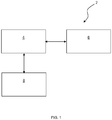
- FIG. 1 shows a medical imaging system 2 according to an embodiment of the invention.
- the medical imaging system generally comprises a processor 4, a microwave antenna array 6 in communication with the processor 4, and an ablation system 8 in communication with the processor 4.
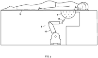
- the microwave antenna array 6 may form part of a table 10 on which a patient lies in a prone position.
- the ablation system 8 is connected to the table 10 or otherwise located in a fixed or known position relative to the table 10.
- the ablation system 8 comprises an articulated arm 12 which carries an ablation needle 14 (which may comprise one or more individual needles).
- the articulated arm 12 allows the ablation needle 14 to be maneuvered relative to the antenna array 6.
- the ablation system 8 may be a radiofrequency ablation (RFA) system which uses a needle electrode or a microwave ablation (MWA) system which uses a needle antenna.
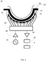
- the antenna array 6 comprises a plurality N of antennae 16 which are arranged over the surface of, or within, a shell substrate 18.
- the shell 18 has a curved profile as shown.
- the shell 18 is part or hemi-spherical and is configured to approximate the shape of a breast.
- the antennae 16 are arranged over the shell 18 such that they all point to a common focal point.
- the antennae 16 are each electrically connected to a switching matrix 20.
- the switching matrix 20 is in turn connected to both a transmit path and a receive path.
- the transmit path comprises a signal generator 22 coupled to an amplifier 24.
- the receive path comprises an amplifier 26 coupled to a detector 28 and the processor 4.
- the switching matrix 20 selectively couples each of the antennae 16 to either the transmit path or the receive path.
- the antenna array 6 is operated in a multi-static fashion. Specifically, the switching matrix 20 is controlled so as to connect one of the antennae 16 to the transmit path and the remaining antennae 16 to the receive path.
- the signal generator 22 generates a stepped frequency continuous wave (CW) signal which is amplified by the amplifier 24 and then transmitted by the antenna 16 connected to the transmit path.
- the stepped frequency continuous wave signal is a sequential series of pulses of continuous wave energy, where each pulse has its frequency stepped up across a range of frequencies, typically within the 3-8 GHz range.
- the other antennae 16 receive the transmitted signal and the received signal is detected and then recorded by the processor 4.
- FIG. 4 shows a flowchart of a data acquisition method.
- the acquisition process may be repeated with the antenna array 6 translated (i.e. rotated about its rotational axis). This may allow fixed errors to be cancelled from the detected signals.
- the shell 18 receives a cup 30.
- the cup 30 has a complementary shape to the shell 18 such that if fits snugly within the shell 18.
- the outside of the cup 30 and the inside of the shell 18 may have threaded portions to enable a threaded engagement between the cup 30 and the shell 18.
- the threaded engagement between the cup 30 and the shell 18 may be used to translate the antenna array 6 relative to the breast 36, as described previously.
- a layer of coupling fluid may be inserted in the gap 31 between the shell 18 and the cup 30 so as to improve the coupling between the antennae 16 and the cup 30 in order to minimise signal loss and thus improve transmission of the microwave signal.
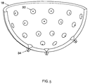
- the shell 18 comprises a plurality of apertures 32 which are distributed across the surface of the shell 18.
- Each aperture 32 extends through the thickness of the shell 18 and tapers such that the aperture 32 is wider at the inner surface of the shell 18 than at the outer surface.
- the apertures 32 are therefore frustoconical.
- Each aperture 32 is provided with a sealing nozzle or gasket 34.
- the gaskets 34 are provided in order to prevent the coupling fluid from leaking through the apertures 32.
- the cup 30 also comprises a set of corresponding apertures in order to provide access from the exterior of the shell 18 through to the interior of the cup 30.
- a patient lies on the table 10 in a prone position such that their breast 36 sits in the cup 30.
- a layer of coupling fluid may also be provided in the gap 35 between the cup 30 and the breast 36 in order to improve coupling between the antennae 16 and the breast 36.
- one or more inserts may be placed inside the cup 30 so as to enable a better fit between the internal surface of the cup 30 and the breast 36.
- a plurality of such inserts may be provided, each having different shapes and sizes, to enable the system to be better adapted to breasts of different shapes and sizes.
- the inserts may be made from the same material as the cup (e.g. ceramic).
- the antenna 16 connected to the transmit path illuminates the breast 36 with the microwave signal.
- the signal is scattered by the breast tissue and the scattered signal is received at each of the non-transmitting antennae 16 where it is detected and recorded. This process is repeated for each antenna 16, as described previously with reference to the data acquisition method shown in Figure 4 .
- the processor 4 may record the relative difference between the measured phase and amplitude of the transmitted signal as compared to the phase and amplitude of the scattered signal, recorded as a complex number (having real and imaginary parts).
- the signal detected at each antenna 16 will generally comprise three components: a component arising from mutual coupling between the transmitting and receiving antennas 16; a component arising from radiation which reflects off the skin of the breast 36; and a component arising from radiation which reflects off structures within the breast (such as tumours).
- Tumours can generate identifiable reflections as they exhibit much higher dielectric properties than adipose tissues due to their significant water content.
- the mutual and skin reflection components may be removed or at least mitigated from the data set in order to improve the detectability of reflections resulting from the presence of tumours within the breast.
- the acquired data set may be used by the processor 4 to construct an image of the internal structure of the breast 36.
- Data reconstruction may be performed using Phased Array (frequency domain), Delay and Sum (DAS - time domain) techniques or any other suitable technique. From this, the processor 4 is able to identify (possibly, with additional user input or confirmation) a region of interest (if present) in which a possible tumour or other pathology may exist. The presence of a tumour or other pathology may be confirmed by taking a biopsy from the region of interest.
- the ablation system 8 may be used to treat the target.
- the processor 4 may guide the articulated arm 12 so as to locate the ablation needle 14 in the desired position and orientation for accessing the target.
- the articulated arm 12 may be a robotic arm such that it can manipulate the ablation needle 14 to the required position and orientation based on coordinates provided by the processor 4.
- the articulated arm 12 may be actuated by a user but provide feedback via appropriate sensors to the user or processor 4 of its current position so that it can be brought into the proper position and orientation.
- the articulated arm 12 may be dispensed with and the ablation needle 14 itself provide feedback via sensors on its current position and orientation to the processor 4 or user.
- the shell 18 comprises a plurality of apertures 32 which provide access to the breast 36 for the ablation needle 14.
- the processor 4 may determine the most appropriate aperture 32 for performing the ablation procedure. In particular, the processor 4 may determine the closest aperture 32 to the target. As described previously, the apertures 32 are frustoconical such that the ablation needle 14 can be introduced through the aperture 32 at a range of angles.
- the ablation needle 14 With the ablation needle 14 guided to the appropriate position and orientation for accessing the target, the ablation needle 14 can be inserted into the breast 36 and directed to the target.
- the antenna array 6 can be used to confirm that the needle is coincident with the target by again illuminating the breast 36 with microwave signals and detecting scattered signals from the ablation needle 14.
- the processor 4 may confirm that the ablation needle 14 is appropriately positioned prior to activation by updating the image.
- the image of the breast 36 (or only the relevant portion) may be updated as the ablation needle 14 passes into the breast 36 towards and into the target.
- the processor 4 may adjust the signal processing performed such that it is optimised for speed and mapping a known object in space.
- the data acquisition and analysis performed by the processor during the guidance of the ablation needle 14 may be faster than during imaging for the purpose of initially identifying the region of interest.
- the ablation system 8 is activated so as to perform the ablation procedure (via a suitable signal generator and other electronics) in accordance with known practices and systems in order to heat the target so as to denature or kill cancerous cells.
- the parameters of the ablation procedure are controlled to ensure that the heating is localized to the target. If additional targets are present then the ablation needle 14 may again be guided to the next target either directly or following withdrawal of the ablation needle 14 from the breast.
- the processor 4 and microwave antenna array 6 may be used to monitor the ablation procedure as it is being performed and to provide feedback to the clinician.
- the effect on the target may be measured directly by imaging the breast at a different frequency from the frequency of the ablation signal.
- the microwave antenna array 6 may detect the microwave radiation from the needle itself which is spatially resolved.
- the processor 4 can therefore provide feedback on the propagation of the microwave radiation within the target and beyond.
- the parameters can therefore be controlled to ensure that the entire target (and no more) is ablated.
- the microwave radiation also gives information about the impedance match between the needle antenna and the surrounding tissue, allowing the needle antenna impedance to be better adjusted to optimise coupling of energy from the antenna to the surrounding tissue.
- the target may continue to be imaged after the ablation procedure has been completed (e.g. immediately after or after a period of several days or weeks) so that the efficacy of the procedure can be understood.
- Such monitoring may be used to plan further treatment, such as further ablation procedures.
- the data provided by the processor 4 and the microwave antenna array 6 provides a measure of the local conductivity and/or permittivity of the tissue being imaged. It has been found that conductivity and permittivity vary with temperature. Monitoring of the conductivity and/or permittivity of the target during the ablation procedure therefore provides information regarding the temperature of the target (or the surrounding tissue). A temperature profile of the target or a single average temperature for the entire region may be obtained from the data. The parameters (including the duration of the procedure) can be accurately controlled based on this temperature information to ensure that the tissue within the target reaches the required ablation temperature, but does not significantly exceed this in order to avoid propagation to surrounding tissue.
- Ablation needles are typically made of steel which generally provides a strong microwave scattering signal and can therefore be reliably located.
- the ablation needle 14 may bend as it passes through tissue, and/or the scattering signal may be modified by surrounding tissue. To allow for either of these more complex cases, the ablation needle 14 may be modified so that it is more easily identifiable.
- the ablation needle 14 may be provided with a marker which is more easily discriminated by microwave radar in order to determine needle tip location and overall orientation more accurately.
- the marker should have a distinctive radar signature that can be characterised rapidly for guidance purposes.
- the marker may include:
- the ablation needle 14 may be able to deposit such a marker at the site of the target in order to allow the site to be identified more easily in subsequent procedures, such as further ablation treatment or surgery.
- the ablation needle 14 itself may radiate the microwave signal, rather than scattering signals generated by the antennae 16.
- the ablation needle 14 may have an integrated coaxial feed line which supplies the signal to the tip of the needle.
- the ablation system 8 is a MWA system
- the ablation needle 14 may radiate the microwave signal at the same frequency as that of microwave ablation or at another frequency.
- the needle antenna 14 may have an integrated coaxial feed line which supplies the signal to the tip of the needle or may employ the same coaxial feed line used in MWA itself.
- the ablation needle 14 may comprise an integrated microwave source.
- the antennae 16 of the antenna array 6 therefore all (or a subset of the antennae 16) act to receive the signal emitted by the ablation needle 14.
- Using the ablation needle 14 as the signal source avoids having to sequentially connect each of the antennae 16 to the transmit path and thus allows the scan time to be drastically reduced, potentially allowing real time operation.
- the ablation needle 14 has been described as being automatically guided to the target, it may instead be manually guided, with its location being tracked inside the body part and displayed on a model of the body part along with the target's location so that it can be guided towards the target.
- a vector which extends from the end of the ablation needle may be projected onto the image to show the trajectory of the needle and to help the clinician guide the needle towards the target.
- the image may be repeatedly updated as the needle moves towards the target.
- the shell 18 has been described as having a plurality of frustoconical apertures 32 for providing access to the breast, other arrangements may be used.
- the shell 18 may have a plurality of circumferential slots. The angular spacing of the slots corresponds to the available angular rotation of the antenna array 6. Each slot, under rotation, gives access to a volume of tissue which typically overlaps to some degree with adjacent slots in order to offer some options in needle placement.
- Figure 6 shows an alternative embodiment of a shell 118 which may be used where the antenna array 6 is able to rotate through 180°.
- the shell 118 comprises a single slot 132 which passes through the axis of rotation from each side of the shell 118 (or two diametrically opposed slots with a discontinuity at the axis of rotation).
- the shell 118 is rotatable through 180° such that the slot 132 is able to allow the ablation needle 14 to access the entire breast 36.
- the shell 118 is used with a cup 130 and, if required, an insert 138.
- the cup 130 has a complementary shape to the shell 118 such that if fits snugly within the shell 118 and, in turn, the insert 138 has a complementary shape to the cup 130 such that if fits snugly within the cup 130.
- the cup 130 is provided with a slot 140 which corresponds to the slot 132 of the shell 118.
- the insert 138 is provided with a slot 142 which corresponds to the slot 132 of the shell 118.
- the cup 130 and, if used, the insert 138 are disposed within the shell 118 such that the slots 132, 140, 142 of the shell 118, cup 130 and insert 138 are all aligned with one another.
- the slots 132, 140, 142 therefore provide access to the breast 36 from the exterior of the shell 118.
- the cup 130 and insert 138 are connected to the shell 118 so as to prevent relative rotation and thus to maintain the alignment of the slots 132, 140, 142.
- the cup and insert may be provided with locating tabs which prevent rotation relative to the shell 118.
- a layer of coupling fluid may be inserted in the gap between the shell 118 and the cup 130 and also in the gap between the cup 130 and the insert 138.
- the slots 132, 140, 142 may be fitted with a gasket to prevent the escape of coupling fluid.
- a disposable tray 144 is used.
- the tray 144 is made from a biocompatible polymer, such as PEEK, HIPS, PET.
- the tray comprises a central section 146 which is curved to conform to the underlying cup 130 or insert 138.
- the central section 146 may be part or hemi-spherical.
- Disposable trays may be provided in different sizes that correspond to the internal dimensions of each available insert (and cup) respectively so that a low-compliance fit to the underlying surface is achieved.
- a planar rim 148 extends from the central section 146.
- the material thickness over the central section 146 may be less than that of the planar rim 148.
- the planar rim 148 may therefore provide structural rigidity to the disposable tray 144, while the thin central section 146 ensures that the dielectric properties of the matching interface between the cup/inserts and patient is not disturbed.
- the disposable tray 144 is held stationary against the breast 36 while the shell 118, cup 130 and insert 138 are rotated to properly align the slots 132, 140, 142 with the desired location over the breast 36 from which to perform the ablation procedure.
- the disposable tray 144 may be provided with location tabs 150 or the like which engage with complementary features on a stationary housing (not shown) of the antenna array 6.
- the disposable tray 144 is therefore fixed in position and prevented from rotating with the shell 118 and the intermediate component(s).
- the disposable tray 144 provides little resistance to the rotation of the shell 118 and so the patient does not feel the shell 118 being moved into position.
- the disposable tray 144 lies over the aligned slots 132, 140, 142 and so obstructs the ablation needle 14.
- the material of the disposable tray 144 is suitably thin than it can be punctured by the needle.
- the ablation needle 14 punctures the tray 144 and breast tissue at a sufficiently high speed and force to minimise the breast tissue shrinking away from the surface of the tray 144. This therefore ensures that the ablation needle 14 is guided accurately to the target.
- the material of the disposable tray 144 may have low-shear characteristics such that when it is punctured by the ablation needle 14, the fracturing characteristic of the polymer can be controlled.
- a drainage arrangement may be included to ensure that any coupling fluid that flows out of the slots in the array is channelled away from the main electro-mechanical components of the system.
- the system described herein is capable of both providing a clinical breast microwave image showing a suspicious lesion and also locating and guiding an ablation needle to the lesion in order to perform an ablation procedure.
- the patient may potentially remain in position throughout the procedure such that the breast retains registration throughout.
- the system provides significant benefits over previously known systems and techniques.
- the system provides precise positioning of the ablation needle with respect to the acquired image, so that the clinician has a high degree of confidence that the proposed trajectory of the needle will intersect the target. This reduces the number of needle insertions/withdrawals and the risk of seeding malignant cells along multiple needle tracks.
- the target may be identified by performing a biopsy of a region of interest.
- the guidance of the biopsy may be achieved in a similar manner to that used for the ablation procedure.
- the ablation needle may be replaced by a biopsy needle during this procedure or a separate biopsy probe provided as part of the system.
- the processor 4 need not display, or indeed, generate, an image of the internal structure of the breast in order to identify a region of interest.
- the region of interest may instead be determined based on the raw data.
- the cup of the antenna array may be dispensed with or integrated into the shell in which the antennae are located.
- the system may employ multiple transmit and receive paths, such that data can be recorded from multiple antennas simultaneously, and may even comprise a number of transmit and receive paths corresponding to the number of antennas, such that data can be recorded from all antennas simultaneously.
- the switching matrix could be removed thus allowing each antenna to be connected to a transmitting/receiving device.
- more than one antenna may be operated at a time in a frequency multiplexed operation. Multiplexed operation may have significant advantages where high speed tracking of the needle is required.
Description
- The invention relates to a medical imaging system and method and particularly, although not exclusively, to an apparatus and method which incorporates guidance of a an ablation probe to a target.
- Various medical imaging techniques are known for examining the human body. Such imaging techniques may be used to interrogate tissues and organs in order to identify abnormalities, such as tumours or lesions. For example, X-ray (mammography), microwave imaging, ultrasound, MRI are all common imaging modalities. Such techniques are commonly used to examine breast tissue, but may also be used in other areas of the body, such as the liver, pancreas, prostate, thyroid, lungs, ovaries and lymph nodes.
- Once identified, a target, such as a tumour, can be treated using a suitable procedure. Typically, surgical resection has been the standard treatment of primary solid tumours localized to organs such as the lung, colon, and breast. However, needle ablation techniques such as radiofrequency ablation (RFA) and microwave ablation (MWA) provide a minimally invasive, nonsurgical alternative.
- RFA uses a needle electrode to deliver radiofrequency current to the target which causes localized heating sufficient to achieve necrosis of malignant tissue, with only minimal destruction of the surrounding healthy cells.
- RFA relies on electrical conduction through the tissue: RF current is able to pass through tissue because of the abundance of ionic fluid present. However, tissue is not a perfect conductor and RF current causes resistive heating (the Joule effect). Direct RF heating occurs within a few millimeters of the applicator (electrode), but a large portion of the final ablation zone is created when thermal conduction pushes heat into more peripheral areas around the electrode.
- MWA uses a needle antenna or antennae to deliver microwave electromagnetic (EM) energy to the target.
- MWA occurs as a result of dielectric heating of tissue. Dielectric heating occurs when an alternating EM field is applied to an imperfect dielectric material. In tissue, heating occurs because the EM field forces water molecules in the tissue to oscillate. The bound water molecules tend to oscillate out of phase with the applied fields, so some of the EM energy is absorbed and converted to heat. The best EM absorbers contain a high percentage of water (e.g., most solid organs) while less heating occurs in tissues with low water content (e.g., fat).
-
US 2007/0197891 andUS 2008/0027313 describe known invasive medical devices, and in particular to known catheters, each of which may be deployed within the body of a patient under the control of a magnetic-based navigation system. - The invention seeks to provide a system which improves the treatment of a target within a body part.
- In accordance with an aspect of the invention, there is provided a medical imaging system comprising: a microwave antenna array comprising a transmitting antenna and a plurality of receiving antennae, wherein the transmitting antenna is configured to transmit microwave signals so as to illuminate a body part of a patient and the receiving antennae are configured to receive the microwave signals following scattering within the body part; a processor configured to process the scattered microwave signals and generate an output indicative of the internal structure of the body part to identify a target within the body part; and an ablation probe comprising an ablation needle movable relative to the microwave antenna array. The microwave antenna array is formed on a substrate and the substrate comprises one or more openings configured to receive the ablation needle to provide access to the body part. The receiving antennae are further configured to receive microwave signals scattered or emitted by the ablation needle and the processor is further configured to monitor a position of the ablation needle as it is guided to the target within the body part.
- The processor may be further configured to guide the ablation needle to the target within the body part.
- The openings may be conical.
- The openings may be provided with sealing gaskets.
- The openings may comprise one or more slots.
- The substrate may comprise a plurality of said openings and the processor may be configured to select one of the plurality of openings for introducing the ablation needle.
- The ablation probe may be mounted on an articulated arm configured to maneuver the ablation probe relative to the antenna array.
- The articulated arm may be a robotic arm.
- The ablation needle may be configured to emit microwave signals which are received by the receiving antennae.
- The ablation needle may comprise a coaxial feed line which transmits the microwave signals.
- The ablation needle may comprise a microwave marker at its tip.
- The processor may be configured to perform a first data acquisition and analysis operation when identifying the target and to perform a second data acquisition and analysis operation when guiding the ablation needle, the second data acquisition and analysis operation being faster than the first data acquisition and analysis operation.
- The processor may be further configured to monitor the target during an ablation procedure performed by the ablation probe.
- The receiving antennae of the microwave antenna array may receive a signal emitted by the ablation needle.
- The processor may be further configured to determine a temperature or temperature profile of the target based on permittivity and/or conductivity values measured from the scattered microwave signals during an ablation procedure.
- In accordance with an aspect not falling within the scope of the present invention as claimed there is provided a medical imaging method comprising: illuminating a body part of a patient with microwave signals emitted by a transmitting antenna of an microwave antenna array; receiving the microwave signals following scattering within the body part at a plurality of receiving antennae of the microwave antenna array; processing the scattered microwave signals to generate an output indicative of the internal structure of the body part; identifying a target within the body part from the output; guiding an ablation needle of an ablation probe to the target within the body part by monitoring microwave signals scattered or emitted by the ablation needle using the receiving antennae; and performing an ablation procedure using the ablation probe in which a signal is emitted from the ablation needle so as to heat the target.
- The method may further comprise: monitoring the target during the ablation procedure.
- Monitoring the target may comprise receiving at the receiving antennae of the microwave antenna array a signal emitted by the ablation needle during the ablation procedure.
- Monitoring the target may comprise determining permittivity and/or conductivity values for the target from the scattered microwave signals received during the ablation procedure; and determining a temperature or temperature profile of the target based on the measured permittivity and/or conductivity.
- For a better understanding of the invention, and to show more clearly how it may be carried into effect, reference will now be made, by way of example, to the accompanying drawings, in which:-
-
Figure 1 is a system diagram of a medical imaging system according to an embodiment of the invention; -
Figure 2 is a schematic side view of an example implementation of the medical imaging system; -
Figure 3 is a schematic view of imaging portion of the medical imaging system; -
Figure 4 is a flowchart depicting a sampling method; -
Figure 5 is perspective cross-sectional view of an antenna shell of the medical imaging system; -
Figure 6 is a perspective view of an alternative antenna shell used in the medical imaging system; and -
Figure 7 is an exploded view of an assembly comprising the antenna shell ofFigure 6 . -
Figure 1 shows amedical imaging system 2 according to an embodiment of the invention. The medical imaging system generally comprises aprocessor 4, amicrowave antenna array 6 in communication with theprocessor 4, and anablation system 8 in communication with theprocessor 4. - As shown in
Figure 2 , themicrowave antenna array 6 may form part of a table 10 on which a patient lies in a prone position. Theablation system 8 is connected to the table 10 or otherwise located in a fixed or known position relative to the table 10. Theablation system 8 comprises anarticulated arm 12 which carries an ablation needle 14 (which may comprise one or more individual needles). The articulatedarm 12 allows theablation needle 14 to be maneuvered relative to theantenna array 6. - The
ablation system 8 may be a radiofrequency ablation (RFA) system which uses a needle electrode or a microwave ablation (MWA) system which uses a needle antenna. As shown inFigure 3 , theantenna array 6 comprises a plurality N ofantennae 16 which are arranged over the surface of, or within, ashell substrate 18. Theshell 18 has a curved profile as shown. In particular, theshell 18 is part or hemi-spherical and is configured to approximate the shape of a breast. Theantennae 16 are arranged over theshell 18 such that they all point to a common focal point. - The
antennae 16 are each electrically connected to aswitching matrix 20. Theswitching matrix 20 is in turn connected to both a transmit path and a receive path. The transmit path comprises asignal generator 22 coupled to anamplifier 24. The receive path comprises anamplifier 26 coupled to adetector 28 and theprocessor 4. - The
switching matrix 20 selectively couples each of theantennae 16 to either the transmit path or the receive path. - The
antenna array 6 is operated in a multi-static fashion. Specifically, the switchingmatrix 20 is controlled so as to connect one of theantennae 16 to the transmit path and the remainingantennae 16 to the receive path. Thesignal generator 22 generates a stepped frequency continuous wave (CW) signal which is amplified by theamplifier 24 and then transmitted by theantenna 16 connected to the transmit path. The stepped frequency continuous wave signal is a sequential series of pulses of continuous wave energy, where each pulse has its frequency stepped up across a range of frequencies, typically within the 3-8 GHz range. Theother antennae 16 receive the transmitted signal and the received signal is detected and then recorded by theprocessor 4. -
Figure 4 shows a flowchart of a data acquisition method. As shown, the switchingmatrix 20 connects an antenna m of the N antennae to the transmit path. All other antennae 16 (n = 1...N, n≠m) are connected to the receive path and detect the transmitted signal (possibly in a time-sharing arrangement). If mtN, the switchingmatrix 20 steps to the next antenna 16 (m = m + 1) to be connected to the transmit path. This is repeated until all antennae 16 have been connected to the transmit path. The acquisition process may be repeated with theantenna array 6 translated (i.e. rotated about its rotational axis). This may allow fixed errors to be cancelled from the detected signals. - Referring again to
Figure 3 , theshell 18 receives acup 30. Thecup 30 has a complementary shape to theshell 18 such that if fits snugly within theshell 18. - The outside of the
cup 30 and the inside of theshell 18 may have threaded portions to enable a threaded engagement between thecup 30 and theshell 18. The threaded engagement between thecup 30 and theshell 18 may be used to translate theantenna array 6 relative to the breast 36, as described previously. - A layer of coupling fluid (dielectric constant controlled fluid) may be inserted in the
gap 31 between theshell 18 and thecup 30 so as to improve the coupling between theantennae 16 and thecup 30 in order to minimise signal loss and thus improve transmission of the microwave signal. - As shown in
Figure 5 , theshell 18 comprises a plurality ofapertures 32 which are distributed across the surface of theshell 18. Eachaperture 32 extends through the thickness of theshell 18 and tapers such that theaperture 32 is wider at the inner surface of theshell 18 than at the outer surface. Theapertures 32 are therefore frustoconical. Eachaperture 32 is provided with a sealing nozzle orgasket 34. Thegaskets 34 are provided in order to prevent the coupling fluid from leaking through theapertures 32. Thecup 30 also comprises a set of corresponding apertures in order to provide access from the exterior of theshell 18 through to the interior of thecup 30. - In use, a patient lies on the table 10 in a prone position such that their breast 36 sits in the
cup 30. A layer of coupling fluid may also be provided in thegap 35 between thecup 30 and the breast 36 in order to improve coupling between theantennae 16 and the breast 36. - Although not shown, one or more inserts may be placed inside the
cup 30 so as to enable a better fit between the internal surface of thecup 30 and the breast 36. For example, a plurality of such inserts may be provided, each having different shapes and sizes, to enable the system to be better adapted to breasts of different shapes and sizes. The inserts may be made from the same material as the cup (e.g. ceramic). - The
antenna 16 connected to the transmit path illuminates the breast 36 with the microwave signal. The signal is scattered by the breast tissue and the scattered signal is received at each of thenon-transmitting antennae 16 where it is detected and recorded. This process is repeated for eachantenna 16, as described previously with reference to the data acquisition method shown inFigure 4 . - The
processor 4 may record the relative difference between the measured phase and amplitude of the transmitted signal as compared to the phase and amplitude of the scattered signal, recorded as a complex number (having real and imaginary parts). - The signal detected at each
antenna 16 will generally comprise three components: a component arising from mutual coupling between the transmitting and receivingantennas 16; a component arising from radiation which reflects off the skin of the breast 36; and a component arising from radiation which reflects off structures within the breast (such as tumours). Tumours can generate identifiable reflections as they exhibit much higher dielectric properties than adipose tissues due to their significant water content. The mutual and skin reflection components may be removed or at least mitigated from the data set in order to improve the detectability of reflections resulting from the presence of tumours within the breast. - The acquired data set may be used by the
processor 4 to construct an image of the internal structure of the breast 36. Data reconstruction may be performed using Phased Array (frequency domain), Delay and Sum (DAS - time domain) techniques or any other suitable technique. From this, theprocessor 4 is able to identify (possibly, with additional user input or confirmation) a region of interest (if present) in which a possible tumour or other pathology may exist. The presence of a tumour or other pathology may be confirmed by taking a biopsy from the region of interest. - Once the processor 4 (and any subsequent biopsy or other analysis) has identified a target, the
ablation system 8 may be used to treat the target. In particular, theprocessor 4 may guide the articulatedarm 12 so as to locate theablation needle 14 in the desired position and orientation for accessing the target. The articulatedarm 12 may be a robotic arm such that it can manipulate theablation needle 14 to the required position and orientation based on coordinates provided by theprocessor 4. Alternatively, the articulatedarm 12 may be actuated by a user but provide feedback via appropriate sensors to the user orprocessor 4 of its current position so that it can be brought into the proper position and orientation. As a further alternative, the articulatedarm 12 may be dispensed with and theablation needle 14 itself provide feedback via sensors on its current position and orientation to theprocessor 4 or user. - As described previously, the
shell 18 comprises a plurality ofapertures 32 which provide access to the breast 36 for theablation needle 14. - The
processor 4 may determine the mostappropriate aperture 32 for performing the ablation procedure. In particular, theprocessor 4 may determine theclosest aperture 32 to the target. As described previously, theapertures 32 are frustoconical such that theablation needle 14 can be introduced through theaperture 32 at a range of angles. - With the
ablation needle 14 guided to the appropriate position and orientation for accessing the target, theablation needle 14 can be inserted into the breast 36 and directed to the target. Theantenna array 6 can be used to confirm that the needle is coincident with the target by again illuminating the breast 36 with microwave signals and detecting scattered signals from theablation needle 14. Specifically, theprocessor 4 may confirm that theablation needle 14 is appropriately positioned prior to activation by updating the image. The image of the breast 36 (or only the relevant portion) may be updated as theablation needle 14 passes into the breast 36 towards and into the target. - During the guidance of the
ablation needle 14, theprocessor 4 may adjust the signal processing performed such that it is optimised for speed and mapping a known object in space. The data acquisition and analysis performed by the processor during the guidance of theablation needle 14 may be faster than during imaging for the purpose of initially identifying the region of interest. - With the
ablation needle 14 positioned at or within the target region, theablation system 8 is activated so as to perform the ablation procedure (via a suitable signal generator and other electronics) in accordance with known practices and systems in order to heat the target so as to denature or kill cancerous cells. The parameters of the ablation procedure are controlled to ensure that the heating is localized to the target. If additional targets are present then theablation needle 14 may again be guided to the next target either directly or following withdrawal of theablation needle 14 from the breast. - The
processor 4 andmicrowave antenna array 6 may be used to monitor the ablation procedure as it is being performed and to provide feedback to the clinician. In particular, the effect on the target may be measured directly by imaging the breast at a different frequency from the frequency of the ablation signal. - Alternatively or in addition, where the
ablation system 8 is a MWA system, themicrowave antenna array 6 may detect the microwave radiation from the needle itself which is spatially resolved. Theprocessor 4 can therefore provide feedback on the propagation of the microwave radiation within the target and beyond. The parameters can therefore be controlled to ensure that the entire target (and no more) is ablated. The microwave radiation also gives information about the impedance match between the needle antenna and the surrounding tissue, allowing the needle antenna impedance to be better adjusted to optimise coupling of energy from the antenna to the surrounding tissue. - The target may continue to be imaged after the ablation procedure has been completed (e.g. immediately after or after a period of several days or weeks) so that the efficacy of the procedure can be understood. Such monitoring may be used to plan further treatment, such as further ablation procedures.
- The data provided by the
processor 4 and themicrowave antenna array 6 provides a measure of the local conductivity and/or permittivity of the tissue being imaged. It has been found that conductivity and permittivity vary with temperature. Monitoring of the conductivity and/or permittivity of the target during the ablation procedure therefore provides information regarding the temperature of the target (or the surrounding tissue). A temperature profile of the target or a single average temperature for the entire region may be obtained from the data. The parameters (including the duration of the procedure) can be accurately controlled based on this temperature information to ensure that the tissue within the target reaches the required ablation temperature, but does not significantly exceed this in order to avoid propagation to surrounding tissue. - Ablation needles are typically made of steel which generally provides a strong microwave scattering signal and can therefore be reliably located. However, the
ablation needle 14 may bend as it passes through tissue, and/or the scattering signal may be modified by surrounding tissue. To allow for either of these more complex cases, theablation needle 14 may be modified so that it is more easily identifiable. In particular, theablation needle 14 may be provided with a marker which is more easily discriminated by microwave radar in order to determine needle tip location and overall orientation more accurately. - Microwave markers will typically have one or more of the following characteristics:
- Enhanced overall microwave scattering amplitude over surrounding tissue
- Microwave scattering that is a strong function of frequency - the continuous wave radar is well suited to measure scattering as a function of frequency
- Scattering anisotropy - the
hemispherical antenna array 6 is able to characterize scattering over a wide solid angle. - The marker should have a distinctive radar signature that can be characterised rapidly for guidance purposes. For example, the marker may include:
- Radio frequency identification tags
- Microwave metamaterials
- Ferromagnetically or ferrimagnetically resonant materials within the UWB band, such as ferrites.
- The
ablation needle 14 may be able to deposit such a marker at the site of the target in order to allow the site to be identified more easily in subsequent procedures, such as further ablation treatment or surgery. - Alternatively, the
ablation needle 14 itself may radiate the microwave signal, rather than scattering signals generated by theantennae 16. For example, theablation needle 14 may have an integrated coaxial feed line which supplies the signal to the tip of the needle. Where theablation system 8 is a MWA system, theablation needle 14 may radiate the microwave signal at the same frequency as that of microwave ablation or at another frequency. In this case, theneedle antenna 14 may have an integrated coaxial feed line which supplies the signal to the tip of the needle or may employ the same coaxial feed line used in MWA itself. - Alternatively, the
ablation needle 14 may comprise an integrated microwave source. - The
antennae 16 of theantenna array 6 therefore all (or a subset of the antennae 16) act to receive the signal emitted by theablation needle 14. Using theablation needle 14 as the signal source avoids having to sequentially connect each of theantennae 16 to the transmit path and thus allows the scan time to be drastically reduced, potentially allowing real time operation. - Although the
ablation needle 14 has been described as being automatically guided to the target, it may instead be manually guided, with its location being tracked inside the body part and displayed on a model of the body part along with the target's location so that it can be guided towards the target. A vector which extends from the end of the ablation needle may be projected onto the image to show the trajectory of the needle and to help the clinician guide the needle towards the target. The image may be repeatedly updated as the needle moves towards the target. - Although the
shell 18 has been described as having a plurality offrustoconical apertures 32 for providing access to the breast, other arrangements may be used. In particular, theshell 18 may have a plurality of circumferential slots. The angular spacing of the slots corresponds to the available angular rotation of theantenna array 6. Each slot, under rotation, gives access to a volume of tissue which typically overlaps to some degree with adjacent slots in order to offer some options in needle placement. - In particular,
Figure 6 shows an alternative embodiment of ashell 118 which may be used where theantenna array 6 is able to rotate through 180°. Theshell 118 comprises asingle slot 132 which passes through the axis of rotation from each side of the shell 118 (or two diametrically opposed slots with a discontinuity at the axis of rotation). Theshell 118 is rotatable through 180° such that theslot 132 is able to allow theablation needle 14 to access the entire breast 36. - As shown in
Figure 7 , theshell 118 is used with acup 130 and, if required, aninsert 138. Thecup 130 has a complementary shape to theshell 118 such that if fits snugly within theshell 118 and, in turn, theinsert 138 has a complementary shape to thecup 130 such that if fits snugly within thecup 130. - The
cup 130 is provided with aslot 140 which corresponds to theslot 132 of theshell 118. Similarly, theinsert 138 is provided with aslot 142 which corresponds to theslot 132 of theshell 118. Thecup 130 and, if used, theinsert 138 are disposed within theshell 118 such that theslots shell 118,cup 130 and insert 138 are all aligned with one another. Theslots shell 118. Thecup 130 and insert 138 are connected to theshell 118 so as to prevent relative rotation and thus to maintain the alignment of theslots shell 118. - As described with respect to the previous embodiment, a layer of coupling fluid may be inserted in the gap between the
shell 118 and thecup 130 and also in the gap between thecup 130 and theinsert 138. Theslots - To allow the
shell 118 to rotate relative to the breast 36, adisposable tray 144 is used. Thetray 144 is made from a biocompatible polymer, such as PEEK, HIPS, PET. The tray comprises acentral section 146 which is curved to conform to theunderlying cup 130 or insert 138. In particular, thecentral section 146 may be part or hemi-spherical. Disposable trays may be provided in different sizes that correspond to the internal dimensions of each available insert (and cup) respectively so that a low-compliance fit to the underlying surface is achieved. Aplanar rim 148 extends from thecentral section 146. The material thickness over thecentral section 146 may be less than that of theplanar rim 148. Theplanar rim 148 may therefore provide structural rigidity to thedisposable tray 144, while the thincentral section 146 ensures that the dielectric properties of the matching interface between the cup/inserts and patient is not disturbed. - The
disposable tray 144 is held stationary against the breast 36 while theshell 118,cup 130 and insert 138 are rotated to properly align theslots disposable tray 144 may be provided withlocation tabs 150 or the like which engage with complementary features on a stationary housing (not shown) of theantenna array 6. Thedisposable tray 144 is therefore fixed in position and prevented from rotating with theshell 118 and the intermediate component(s). Thedisposable tray 144 provides little resistance to the rotation of theshell 118 and so the patient does not feel theshell 118 being moved into position. - It will be appreciated that the
disposable tray 144 lies over the alignedslots ablation needle 14. However, the material of thedisposable tray 144 is suitably thin than it can be punctured by the needle. Theablation needle 14 punctures thetray 144 and breast tissue at a sufficiently high speed and force to minimise the breast tissue shrinking away from the surface of thetray 144. This therefore ensures that theablation needle 14 is guided accurately to the target. Further, at least over thecentral section 146, the material of thedisposable tray 144 may have low-shear characteristics such that when it is punctured by theablation needle 14, the fracturing characteristic of the polymer can be controlled. - A drainage arrangement may be included to ensure that any coupling fluid that flows out of the slots in the array is channelled away from the main electro-mechanical components of the system.
- The system described herein is capable of both providing a clinical breast microwave image showing a suspicious lesion and also locating and guiding an ablation needle to the lesion in order to perform an ablation procedure.
- As the guidance of the ablation needle is performed by the same system which identifies the target, the patient may potentially remain in position throughout the procedure such that the breast retains registration throughout.
- The system provides significant benefits over previously known systems and techniques. In particular, the system provides precise positioning of the ablation needle with respect to the acquired image, so that the clinician has a high degree of confidence that the proposed trajectory of the needle will intersect the target. This reduces the number of needle insertions/withdrawals and the risk of seeding malignant cells along multiple needle tracks.
- As described previously, the target may be identified by performing a biopsy of a region of interest. The guidance of the biopsy may be achieved in a similar manner to that used for the ablation procedure. In fact, the ablation needle may be replaced by a biopsy needle during this procedure or a separate biopsy probe provided as part of the system.
- Although the system has been described with reference to the imaging of a breast, it will be appreciated that it may be adapted for other areas of the body.
- It will be appreciated that the
processor 4 need not display, or indeed, generate, an image of the internal structure of the breast in order to identify a region of interest. The region of interest may instead be determined based on the raw data. - In other arrangements, the cup of the antenna array may be dispensed with or integrated into the shell in which the antennae are located.
- The system may employ multiple transmit and receive paths, such that data can be recorded from multiple antennas simultaneously, and may even comprise a number of transmit and receive paths corresponding to the number of antennas, such that data can be recorded from all antennas simultaneously. In an alternative topology, the switching matrix could be removed thus allowing each antenna to be connected to a transmitting/receiving device.
- Alternatively, more than one antenna may be operated at a time in a frequency multiplexed operation. Multiplexed operation may have significant advantages where high speed tracking of the needle is required.
- To avoid unnecessary duplication of effort and repetition of text in the specification, certain features are described in relation to only one or several aspects or embodiments of the invention. However, it is to be understood that, where it is technically possible, features described in relation to any aspect or embodiment of the invention may also be used with any other aspect or embodiment of the invention.
- The invention is not limited to the embodiments described herein, and may be modified or adapted without departing from the scope of the present invention.
Claims (15)
- A medical imaging system (2) comprising:a microwave antenna array (6) comprising a transmitting antenna and a plurality of receiving antennae, wherein the transmitting antenna is configured to transmit microwave signals so as to illuminate a body part of a patient and the receiving antennae are configured to receive the microwave signals following scattering within the body part;a processor (4) configured to process the scattered microwave signals and generate an output indicative of the internal structure of the body part to identify a target within the body part;an ablation probe (8) comprising an ablation needle (14) movable relative to the microwave antenna array;wherein the microwave antenna array is formed on a substrate (18), and the substrate (18) comprises one or more openings (32) configured to receive the ablation needle (14) to provide access to the body part; andwherein the receiving antennae are further configured to receive microwave signals scattered or emitted by the ablation needle (14) and the processor (4) is further configured to monitor a position of the ablation needle (14) as it is guided to the target within the body part.
- A medical imaging system as claimed in claim 1, wherein the processor (4) is further configured to guide the ablation needle (14) to the target within the body part.
- A medical imaging system (2) as claimed in claim 1 or 2, wherein the openings (32) are conical.
- A medical imaging system (2) as claimed in claim 1, 2 or 3, wherein the openings (32) are provided with sealing gaskets.
- A medical imaging system (2) as claimed in any preceding claim, wherein the openings (32) comprise one or more slots.
- A medical imaging system (2) as claimed in any preceding claim, wherein the substrate comprises a plurality of said openings (32) and wherein the processor (4) is configured to select one of the plurality of openings (32) for introducing the ablation needle (14).
- A medical imaging system (2) as claimed in any preceding claim, wherein the ablation probe is mounted on an articulated arm configured to maneuver the ablation probe relative to the antenna array (6).
- A medical imaging system (2) as claimed in claim 7, wherein the articulated arm is a robotic arm.
- A medical imaging system (2) as claimed in any preceding claim, wherein the ablation needle (14) is configured to emit microwave signals which are received by the receiving antennae.
- A medical imaging system (2) as claimed in claim 9, wherein the ablation needle (14) comprises a coaxial feed line which transmits the microwave signals.
- A medical imaging system (2) as claimed in any preceding claim, wherein the ablation needle (14) comprises a microwave marker at its tip.
- A medical imaging system (2) as claimed in any preceding claim, wherein the processor (4) is configured to perform a first data acquisition and analysis operation when identifying the target and to perform a second data acquisition and analysis operation when guiding the ablation needle (14), the second data acquisition and analysis operation being faster than the first data acquisition and analysis operation.
- A medical imaging system (2) as claimed in any preceding claim, wherein the processor (4) is further configured to monitor the target during an ablation procedure performed by the ablation probe.
- A medical imaging system (2) as claimed in claim 13, wherein the receiving antennae of the microwave antenna array (6) receive a signal emitted by the ablation needle (14).
- A medical imaging system (2) as claimed in claim 13 or 14, wherein the processor (4) is further configured to determine a temperature or temperature profile of the target based on permittivity and/or conductivity values measured from the scattered microwave signals during an ablation procedure.
Priority Applications (5)
| Application Number | Priority Date | Filing Date | Title |
|---|---|---|---|
| EP17186740.1A EP3443921B1 (en) | 2017-08-17 | 2017-08-17 | A medical imaging system |
| EP20184609.4A EP3738538A1 (en) | 2017-08-17 | 2017-08-17 | Medical imaging system |
| PCT/EP2018/072281 WO2019034758A1 (en) | 2017-08-17 | 2018-08-16 | A medical imaging system and method |
| US16/638,593 US11510728B2 (en) | 2017-08-17 | 2018-08-16 | Medical imaging system and method |
| JP2020508050A JP2020531079A (en) | 2017-08-17 | 2018-08-16 | Medical imaging systems and methods |
Applications Claiming Priority (1)
| Application Number | Priority Date | Filing Date | Title |
|---|---|---|---|
| EP17186740.1A EP3443921B1 (en) | 2017-08-17 | 2017-08-17 | A medical imaging system |
Related Child Applications (2)
| Application Number | Title | Priority Date | Filing Date |
|---|---|---|---|
| EP20184609.4A Division-Into EP3738538A1 (en) | 2017-08-17 | 2017-08-17 | Medical imaging system |
| EP20184609.4A Division EP3738538A1 (en) | 2017-08-17 | 2017-08-17 | Medical imaging system |
Publications (2)
| Publication Number | Publication Date |
|---|---|
| EP3443921A1 EP3443921A1 (en) | 2019-02-20 |
| EP3443921B1 true EP3443921B1 (en) | 2020-09-30 |
Family
ID=59649624
Family Applications (2)
| Application Number | Title | Priority Date | Filing Date |
|---|---|---|---|
| EP17186740.1A Active EP3443921B1 (en) | 2017-08-17 | 2017-08-17 | A medical imaging system |
| EP20184609.4A Withdrawn EP3738538A1 (en) | 2017-08-17 | 2017-08-17 | Medical imaging system |
Family Applications After (1)
| Application Number | Title | Priority Date | Filing Date |
|---|---|---|---|
| EP20184609.4A Withdrawn EP3738538A1 (en) | 2017-08-17 | 2017-08-17 | Medical imaging system |
Country Status (4)
| Country | Link |
|---|---|
| US (1) | US11510728B2 (en) |
| EP (2) | EP3443921B1 (en) |
| JP (1) | JP2020531079A (en) |
| WO (1) | WO2019034758A1 (en) |
Families Citing this family (3)
| Publication number | Priority date | Publication date | Assignee | Title |
|---|---|---|---|---|
| EP3443898B1 (en) * | 2017-08-17 | 2019-12-18 | Micrima Limited | A medical imaging system |
| GB201903540D0 (en) * | 2019-03-15 | 2019-05-01 | Emblation Ltd | Energy delivery system and method |
| CN113558758A (en) * | 2020-04-29 | 2021-10-29 | 孙映辉 | Physical targeting thermotherapy system for tumor treatment and control method thereof |
Family Cites Families (23)
| Publication number | Priority date | Publication date | Assignee | Title |
|---|---|---|---|---|
| FI58719C (en) * | 1979-06-01 | 1981-04-10 | Instrumentarium Oy | DIAGNOSTISERINGSANORDNING FOER BROESTKANCER |
| US5829437A (en) * | 1994-07-01 | 1998-11-03 | Interstitial, Inc. | Microwave method and system to detect and locate cancers in heterogenous tissues |
| US6026173A (en) * | 1997-07-05 | 2000-02-15 | Svenson; Robert H. | Electromagnetic imaging and therapeutic (EMIT) systems |
| US6306132B1 (en) * | 1999-06-17 | 2001-10-23 | Vivant Medical | Modular biopsy and microwave ablation needle delivery apparatus adapted to in situ assembly and method of use |
| JP4652605B2 (en) | 2001-04-05 | 2011-03-16 | ジーイー・メディカル・システムズ・グローバル・テクノロジー・カンパニー・エルエルシー | Shooting aid |
| US6546279B1 (en) * | 2001-10-12 | 2003-04-08 | University Of Florida | Computer controlled guidance of a biopsy needle |
| JP4068399B2 (en) * | 2002-06-03 | 2008-03-26 | アルフレッサファーマ株式会社 | Microwave surgical electrode device |
| US20040143150A1 (en) * | 2002-08-07 | 2004-07-22 | Barzell Winston E. | Template grid system |
| US7828744B2 (en) * | 2003-04-23 | 2010-11-09 | Boston Scientific Scimed, Inc. | Method and assembly for breast immobilization |
| ATE544409T1 (en) * | 2003-06-18 | 2012-02-15 | Koninkl Philips Electronics Nv | REMOTE NEEDLE GUIDE FOR CT FLUOROSCOPY |
| US7280863B2 (en) * | 2003-10-20 | 2007-10-09 | Magnetecs, Inc. | System and method for radar-assisted catheter guidance and control |
| US7266407B2 (en) * | 2003-11-17 | 2007-09-04 | University Of Florida Research Foundation, Inc. | Multi-frequency microwave-induced thermoacoustic imaging of biological tissue |
| US7869854B2 (en) * | 2006-02-23 | 2011-01-11 | Magnetecs, Inc. | Apparatus for magnetically deployable catheter with MOSFET sensor and method for mapping and ablation |
| CA2701132A1 (en) * | 2007-10-08 | 2009-04-16 | Renishaw (Ireland) Limited | Apparatus for stereotactic neurosurgery |
| PL3228272T3 (en) * | 2009-07-28 | 2019-09-30 | Neuwave Medical, Inc. | Ablation system |
| US8430871B2 (en) * | 2009-10-28 | 2013-04-30 | Covidien Lp | System and method for monitoring ablation size |
| US8717430B2 (en) * | 2010-04-26 | 2014-05-06 | Medtronic Navigation, Inc. | System and method for radio-frequency imaging, registration, and localization |
| WO2013173369A2 (en) * | 2012-05-14 | 2013-11-21 | Delphinus Medical Technologies, Inc. | System and method for performing an image-guided biopsy |
| JP6164828B2 (en) * | 2012-12-11 | 2017-07-19 | 株式会社 オリエントマイクロウェーブ | Surgical device position detection system and transmitting antenna |
| WO2014126540A1 (en) * | 2013-02-15 | 2014-08-21 | Mitos Medikal Teknolojiler Sanayi Ve Ticaret Anonim Sirketi | Breast cancer imaging device through microwave surface impedance |
| US10743909B2 (en) * | 2014-04-03 | 2020-08-18 | Corbin Clinical Resources, Llc | Transperineal prostate biopsy device, systems, and methods of use |
| US20160051221A1 (en) * | 2014-08-25 | 2016-02-25 | Covidien Lp | System and Method for Planning, Monitoring, and Confirming Treatment |
| GB2540995A (en) * | 2015-08-04 | 2017-02-08 | Micrima Ltd | Methods, apparatus and computer-readable medium for assessing fit in a system for measuring the internal structure of an object |
-
2017
- 2017-08-17 EP EP17186740.1A patent/EP3443921B1/en active Active
- 2017-08-17 EP EP20184609.4A patent/EP3738538A1/en not_active Withdrawn
-
2018
- 2018-08-16 JP JP2020508050A patent/JP2020531079A/en active Pending
- 2018-08-16 US US16/638,593 patent/US11510728B2/en active Active
- 2018-08-16 WO PCT/EP2018/072281 patent/WO2019034758A1/en active Application Filing
Non-Patent Citations (1)
| Title |
|---|
| None * |
Also Published As
| Publication number | Publication date |
|---|---|
| US11510728B2 (en) | 2022-11-29 |
| EP3738538A1 (en) | 2020-11-18 |
| US20210161587A1 (en) | 2021-06-03 |
| EP3443921A1 (en) | 2019-02-20 |
| JP2020531079A (en) | 2020-11-05 |
| WO2019034758A1 (en) | 2019-02-21 |
Similar Documents
| Publication | Publication Date | Title |
|---|---|---|
| CN106606374B (en) | Planning system and navigation system for ablation procedures | |
| AU2015306770B2 (en) | System and method for planning, monitoring, and confirming treatment | |
| US6582426B2 (en) | Needle kit and method for microwave ablation, track coagulation, and biopsy | |
| US9370392B2 (en) | Heat-sensitive optical probes | |
| JP2020163217A (en) | Apparatus, systems, and methods for localizing markers or tissue structures within a body | |
| EP2359902B1 (en) | System for performing an electrosurgical procedure using an ablation device with an integrated imaging device | |
| US9439712B2 (en) | Heat-distribution indicators, thermal zone indicators, electrosurgical systems including same and methods of directing energy to tissue using same | |
| CN107550568B (en) | Treatment planning system | |
| US11510728B2 (en) | Medical imaging system and method | |
| EP2684534A1 (en) | Heat-distribution indicators and electrosurgical systems including same | |
| EP2452647A1 (en) | Apparatus, system and method for performing an electrosurgical procedure | |
| JP2004520865A (en) | Apparatus for tumor detection and treatment using localized impedance measurements | |
| US11457831B2 (en) | Medical imaging system and method | |
| WO2021034744A1 (en) | Ablation monitoring system and method | |
| EP3174487A1 (en) | Systems and methods for in situ quantification of a thermal environment | |
| WO2017139278A1 (en) | Systems and methods for determining the status of a fluid-cooled microwave ablation system | |
| EP3443898B1 (en) | A medical imaging system |
Legal Events
| Date | Code | Title | Description |
|---|---|---|---|
| PUAI | Public reference made under article 153(3) epc to a published international application that has entered the european phase |
Free format text: ORIGINAL CODE: 0009012 |
|
| STAA | Information on the status of an ep patent application or granted ep patent |
Free format text: STATUS: THE APPLICATION HAS BEEN PUBLISHED |
|
| AK | Designated contracting states |
Kind code of ref document: A1 Designated state(s): AL AT BE BG CH CY CZ DE DK EE ES FI FR GB GR HR HU IE IS IT LI LT LU LV MC MK MT NL NO PL PT RO RS SE SI SK SM TR |
|
| AX | Request for extension of the european patent |
Extension state: BA ME |
|
| STAA | Information on the status of an ep patent application or granted ep patent |
Free format text: STATUS: REQUEST FOR EXAMINATION WAS MADE |
|
| 17P | Request for examination filed |
Effective date: 20190815 |
|
| RBV | Designated contracting states (corrected) |
Designated state(s): AL AT BE BG CH CY CZ DE DK EE ES FI FR GB GR HR HU IE IS IT LI LT LU LV MC MK MT NL NO PL PT RO RS SE SI SK SM TR |
|
| GRAP | Despatch of communication of intention to grant a patent |
Free format text: ORIGINAL CODE: EPIDOSNIGR1 |
|
| STAA | Information on the status of an ep patent application or granted ep patent |
Free format text: STATUS: GRANT OF PATENT IS INTENDED |
|
| INTG | Intention to grant announced |
Effective date: 20200324 |
|
| GRAS | Grant fee paid |
Free format text: ORIGINAL CODE: EPIDOSNIGR3 |
|
| GRAA | (expected) grant |
Free format text: ORIGINAL CODE: 0009210 |
|
| STAA | Information on the status of an ep patent application or granted ep patent |
Free format text: STATUS: THE PATENT HAS BEEN GRANTED |
|
| AK | Designated contracting states |
Kind code of ref document: B1 Designated state(s): AL AT BE BG CH CY CZ DE DK EE ES FI FR GB GR HR HU IE IS IT LI LT LU LV MC MK MT NL NO PL PT RO RS SE SI SK SM TR |
|
| REG | Reference to a national code |
Ref country code: CH Ref legal event code: EP Ref country code: GB Ref legal event code: FG4D |
|
| REG | Reference to a national code |
Ref country code: AT Ref legal event code: REF Ref document number: 1317966 Country of ref document: AT Kind code of ref document: T Effective date: 20201015 |
|
| REG | Reference to a national code |
Ref country code: DE Ref legal event code: R096 Ref document number: 602017024481 Country of ref document: DE |
|
| REG | Reference to a national code |
Ref country code: IE Ref legal event code: FG4D |
|
| REG | Reference to a national code |
Ref country code: DE Ref legal event code: R082 Ref document number: 602017024481 Country of ref document: DE Representative=s name: HL KEMPNER PATENTANWAELTE, SOLICITORS (ENGLAND, DE Ref country code: DE Ref legal event code: R082 Ref document number: 602017024481 Country of ref document: DE Representative=s name: HL KEMPNER PATENTANWALT, RECHTSANWALT, SOLICIT, DE |
|
| PG25 | Lapsed in a contracting state [announced via postgrant information from national office to epo] |
Ref country code: FI Free format text: LAPSE BECAUSE OF FAILURE TO SUBMIT A TRANSLATION OF THE DESCRIPTION OR TO PAY THE FEE WITHIN THE PRESCRIBED TIME-LIMIT Effective date: 20200930 Ref country code: SE Free format text: LAPSE BECAUSE OF FAILURE TO SUBMIT A TRANSLATION OF THE DESCRIPTION OR TO PAY THE FEE WITHIN THE PRESCRIBED TIME-LIMIT Effective date: 20200930 Ref country code: BG Free format text: LAPSE BECAUSE OF FAILURE TO SUBMIT A TRANSLATION OF THE DESCRIPTION OR TO PAY THE FEE WITHIN THE PRESCRIBED TIME-LIMIT Effective date: 20201230 Ref country code: GR Free format text: LAPSE BECAUSE OF FAILURE TO SUBMIT A TRANSLATION OF THE DESCRIPTION OR TO PAY THE FEE WITHIN THE PRESCRIBED TIME-LIMIT Effective date: 20201231 Ref country code: NO Free format text: LAPSE BECAUSE OF FAILURE TO SUBMIT A TRANSLATION OF THE DESCRIPTION OR TO PAY THE FEE WITHIN THE PRESCRIBED TIME-LIMIT Effective date: 20201230 Ref country code: HR Free format text: LAPSE BECAUSE OF FAILURE TO SUBMIT A TRANSLATION OF THE DESCRIPTION OR TO PAY THE FEE WITHIN THE PRESCRIBED TIME-LIMIT Effective date: 20200930 |
|
| REG | Reference to a national code |
Ref country code: AT Ref legal event code: MK05 Ref document number: 1317966 Country of ref document: AT Kind code of ref document: T Effective date: 20200930 |
|
| PG25 | Lapsed in a contracting state [announced via postgrant information from national office to epo] |
Ref country code: LV Free format text: LAPSE BECAUSE OF FAILURE TO SUBMIT A TRANSLATION OF THE DESCRIPTION OR TO PAY THE FEE WITHIN THE PRESCRIBED TIME-LIMIT Effective date: 20200930 Ref country code: RS Free format text: LAPSE BECAUSE OF FAILURE TO SUBMIT A TRANSLATION OF THE DESCRIPTION OR TO PAY THE FEE WITHIN THE PRESCRIBED TIME-LIMIT Effective date: 20200930 |
|
| REG | Reference to a national code |
Ref country code: NL Ref legal event code: MP Effective date: 20200930 |
|
| REG | Reference to a national code |
Ref country code: LT Ref legal event code: MG4D |
|
| PG25 | Lapsed in a contracting state [announced via postgrant information from national office to epo] |
Ref country code: CZ Free format text: LAPSE BECAUSE OF FAILURE TO SUBMIT A TRANSLATION OF THE DESCRIPTION OR TO PAY THE FEE WITHIN THE PRESCRIBED TIME-LIMIT Effective date: 20200930 Ref country code: PT Free format text: LAPSE BECAUSE OF FAILURE TO SUBMIT A TRANSLATION OF THE DESCRIPTION OR TO PAY THE FEE WITHIN THE PRESCRIBED TIME-LIMIT Effective date: 20210201 Ref country code: RO Free format text: LAPSE BECAUSE OF FAILURE TO SUBMIT A TRANSLATION OF THE DESCRIPTION OR TO PAY THE FEE WITHIN THE PRESCRIBED TIME-LIMIT Effective date: 20200930 Ref country code: LT Free format text: LAPSE BECAUSE OF FAILURE TO SUBMIT A TRANSLATION OF THE DESCRIPTION OR TO PAY THE FEE WITHIN THE PRESCRIBED TIME-LIMIT Effective date: 20200930 Ref country code: EE Free format text: LAPSE BECAUSE OF FAILURE TO SUBMIT A TRANSLATION OF THE DESCRIPTION OR TO PAY THE FEE WITHIN THE PRESCRIBED TIME-LIMIT Effective date: 20200930 Ref country code: SM Free format text: LAPSE BECAUSE OF FAILURE TO SUBMIT A TRANSLATION OF THE DESCRIPTION OR TO PAY THE FEE WITHIN THE PRESCRIBED TIME-LIMIT Effective date: 20200930 |
|
| PG25 | Lapsed in a contracting state [announced via postgrant information from national office to epo] |
Ref country code: ES Free format text: LAPSE BECAUSE OF FAILURE TO SUBMIT A TRANSLATION OF THE DESCRIPTION OR TO PAY THE FEE WITHIN THE PRESCRIBED TIME-LIMIT Effective date: 20200930 Ref country code: AT Free format text: LAPSE BECAUSE OF FAILURE TO SUBMIT A TRANSLATION OF THE DESCRIPTION OR TO PAY THE FEE WITHIN THE PRESCRIBED TIME-LIMIT Effective date: 20200930 Ref country code: AL Free format text: LAPSE BECAUSE OF FAILURE TO SUBMIT A TRANSLATION OF THE DESCRIPTION OR TO PAY THE FEE WITHIN THE PRESCRIBED TIME-LIMIT Effective date: 20200930 Ref country code: IS Free format text: LAPSE BECAUSE OF FAILURE TO SUBMIT A TRANSLATION OF THE DESCRIPTION OR TO PAY THE FEE WITHIN THE PRESCRIBED TIME-LIMIT Effective date: 20210130 Ref country code: PL Free format text: LAPSE BECAUSE OF FAILURE TO SUBMIT A TRANSLATION OF THE DESCRIPTION OR TO PAY THE FEE WITHIN THE PRESCRIBED TIME-LIMIT Effective date: 20200930 |
|
| PG25 | Lapsed in a contracting state [announced via postgrant information from national office to epo] |
Ref country code: NL Free format text: LAPSE BECAUSE OF FAILURE TO SUBMIT A TRANSLATION OF THE DESCRIPTION OR TO PAY THE FEE WITHIN THE PRESCRIBED TIME-LIMIT Effective date: 20200930 Ref country code: SK Free format text: LAPSE BECAUSE OF FAILURE TO SUBMIT A TRANSLATION OF THE DESCRIPTION OR TO PAY THE FEE WITHIN THE PRESCRIBED TIME-LIMIT Effective date: 20200930 |
|
| REG | Reference to a national code |
Ref country code: DE Ref legal event code: R097 Ref document number: 602017024481 Country of ref document: DE |
|
| PLBE | No opposition filed within time limit |
Free format text: ORIGINAL CODE: 0009261 |
|
| STAA | Information on the status of an ep patent application or granted ep patent |
Free format text: STATUS: NO OPPOSITION FILED WITHIN TIME LIMIT |
|
| PG25 | Lapsed in a contracting state [announced via postgrant information from national office to epo] |
Ref country code: DK Free format text: LAPSE BECAUSE OF FAILURE TO SUBMIT A TRANSLATION OF THE DESCRIPTION OR TO PAY THE FEE WITHIN THE PRESCRIBED TIME-LIMIT Effective date: 20200930 |
|
| 26N | No opposition filed |
Effective date: 20210701 |
|
| PG25 | Lapsed in a contracting state [announced via postgrant information from national office to epo] |
Ref country code: SI Free format text: LAPSE BECAUSE OF FAILURE TO SUBMIT A TRANSLATION OF THE DESCRIPTION OR TO PAY THE FEE WITHIN THE PRESCRIBED TIME-LIMIT Effective date: 20200930 |
|
| REG | Reference to a national code |
Ref country code: CH Ref legal event code: PL |
|
| PG25 | Lapsed in a contracting state [announced via postgrant information from national office to epo] |
Ref country code: MC Free format text: LAPSE BECAUSE OF FAILURE TO SUBMIT A TRANSLATION OF THE DESCRIPTION OR TO PAY THE FEE WITHIN THE PRESCRIBED TIME-LIMIT Effective date: 20200930 |
|
| REG | Reference to a national code |
Ref country code: BE Ref legal event code: MM Effective date: 20210831 |
|
| PG25 | Lapsed in a contracting state [announced via postgrant information from national office to epo] |
Ref country code: LI Free format text: LAPSE BECAUSE OF NON-PAYMENT OF DUE FEES Effective date: 20210831 Ref country code: CH Free format text: LAPSE BECAUSE OF NON-PAYMENT OF DUE FEES Effective date: 20210831 |
|
| PG25 | Lapsed in a contracting state [announced via postgrant information from national office to epo] |
Ref country code: IS Free format text: LAPSE BECAUSE OF FAILURE TO SUBMIT A TRANSLATION OF THE DESCRIPTION OR TO PAY THE FEE WITHIN THE PRESCRIBED TIME-LIMIT Effective date: 20210130 Ref country code: LU Free format text: LAPSE BECAUSE OF NON-PAYMENT OF DUE FEES Effective date: 20210817 |
|
| PG25 | Lapsed in a contracting state [announced via postgrant information from national office to epo] |
Ref country code: IE Free format text: LAPSE BECAUSE OF NON-PAYMENT OF DUE FEES Effective date: 20210817 Ref country code: BE Free format text: LAPSE BECAUSE OF NON-PAYMENT OF DUE FEES Effective date: 20210831 |
|
| PG25 | Lapsed in a contracting state [announced via postgrant information from national office to epo] |
Ref country code: CY Free format text: LAPSE BECAUSE OF FAILURE TO SUBMIT A TRANSLATION OF THE DESCRIPTION OR TO PAY THE FEE WITHIN THE PRESCRIBED TIME-LIMIT Effective date: 20200930 |
|
| PG25 | Lapsed in a contracting state [announced via postgrant information from national office to epo] |
Ref country code: HU Free format text: LAPSE BECAUSE OF FAILURE TO SUBMIT A TRANSLATION OF THE DESCRIPTION OR TO PAY THE FEE WITHIN THE PRESCRIBED TIME-LIMIT; INVALID AB INITIO Effective date: 20170817 |
|
| PGFP | Annual fee paid to national office [announced via postgrant information from national office to epo] |
Ref country code: IT Payment date: 20230811 Year of fee payment: 7 Ref country code: GB Payment date: 20230822 Year of fee payment: 7 |
|
| PGFP | Annual fee paid to national office [announced via postgrant information from national office to epo] |
Ref country code: FR Payment date: 20230811 Year of fee payment: 7 Ref country code: DE Payment date: 20230821 Year of fee payment: 7 |