EP3443897A1 - Automatic air management system - Google Patents
Automatic air management system Download PDFInfo
- Publication number
- EP3443897A1 EP3443897A1 EP18183645.3A EP18183645A EP3443897A1 EP 3443897 A1 EP3443897 A1 EP 3443897A1 EP 18183645 A EP18183645 A EP 18183645A EP 3443897 A1 EP3443897 A1 EP 3443897A1
- Authority
- EP
- European Patent Office
- Prior art keywords
- air
- pressure
- valve
- catheter
- management system
- Prior art date
- Legal status (The legal status is an assumption and is not a legal conclusion. Google has not performed a legal analysis and makes no representation as to the accuracy of the status listed.)
- Withdrawn
Links
Images


Classifications
-
- A—HUMAN NECESSITIES
- A61—MEDICAL OR VETERINARY SCIENCE; HYGIENE
- A61B—DIAGNOSIS; SURGERY; IDENTIFICATION
- A61B5/00—Measuring for diagnostic purposes; Identification of persons
- A61B5/03—Detecting, measuring or recording fluid pressure within the body other than blood pressure, e.g. cerebral pressure; Measuring pressure in body tissues or organs
- A61B5/036—Detecting, measuring or recording fluid pressure within the body other than blood pressure, e.g. cerebral pressure; Measuring pressure in body tissues or organs by means introduced into body tracts
-
- A—HUMAN NECESSITIES
- A61—MEDICAL OR VETERINARY SCIENCE; HYGIENE
- A61B—DIAGNOSIS; SURGERY; IDENTIFICATION
- A61B5/00—Measuring for diagnostic purposes; Identification of persons
- A61B5/03—Detecting, measuring or recording fluid pressure within the body other than blood pressure, e.g. cerebral pressure; Measuring pressure in body tissues or organs
- A61B5/031—Intracranial pressure
-
- A—HUMAN NECESSITIES
- A61—MEDICAL OR VETERINARY SCIENCE; HYGIENE
- A61B—DIAGNOSIS; SURGERY; IDENTIFICATION
- A61B5/00—Measuring for diagnostic purposes; Identification of persons
- A61B5/68—Arrangements of detecting, measuring or recording means, e.g. sensors, in relation to patient
- A61B5/6846—Arrangements of detecting, measuring or recording means, e.g. sensors, in relation to patient specially adapted to be brought in contact with an internal body part, i.e. invasive
- A61B5/6847—Arrangements of detecting, measuring or recording means, e.g. sensors, in relation to patient specially adapted to be brought in contact with an internal body part, i.e. invasive mounted on an invasive device
- A61B5/6852—Catheters
-
- A—HUMAN NECESSITIES
- A61—MEDICAL OR VETERINARY SCIENCE; HYGIENE
- A61M—DEVICES FOR INTRODUCING MEDIA INTO, OR ONTO, THE BODY; DEVICES FOR TRANSDUCING BODY MEDIA OR FOR TAKING MEDIA FROM THE BODY; DEVICES FOR PRODUCING OR ENDING SLEEP OR STUPOR
- A61M25/00—Catheters; Hollow probes
- A61M25/0097—Catheters; Hollow probes characterised by the hub
-
- A—HUMAN NECESSITIES
- A61—MEDICAL OR VETERINARY SCIENCE; HYGIENE
- A61M—DEVICES FOR INTRODUCING MEDIA INTO, OR ONTO, THE BODY; DEVICES FOR TRANSDUCING BODY MEDIA OR FOR TAKING MEDIA FROM THE BODY; DEVICES FOR PRODUCING OR ENDING SLEEP OR STUPOR
- A61M25/00—Catheters; Hollow probes
- A61M2025/0001—Catheters; Hollow probes for pressure measurement
- A61M2025/0002—Catheters; Hollow probes for pressure measurement with a pressure sensor at the distal end
-
- A—HUMAN NECESSITIES
- A61—MEDICAL OR VETERINARY SCIENCE; HYGIENE
- A61M—DEVICES FOR INTRODUCING MEDIA INTO, OR ONTO, THE BODY; DEVICES FOR TRANSDUCING BODY MEDIA OR FOR TAKING MEDIA FROM THE BODY; DEVICES FOR PRODUCING OR ENDING SLEEP OR STUPOR
- A61M2205/00—General characteristics of the apparatus
- A61M2205/33—Controlling, regulating or measuring
- A61M2205/3331—Pressure; Flow
- A61M2205/3337—Controlling, regulating pressure or flow by means of a valve by-passing a pump
-
- A—HUMAN NECESSITIES
- A61—MEDICAL OR VETERINARY SCIENCE; HYGIENE
- A61M—DEVICES FOR INTRODUCING MEDIA INTO, OR ONTO, THE BODY; DEVICES FOR TRANSDUCING BODY MEDIA OR FOR TAKING MEDIA FROM THE BODY; DEVICES FOR PRODUCING OR ENDING SLEEP OR STUPOR
- A61M2210/00—Anatomical parts of the body
- A61M2210/06—Head
- A61M2210/0687—Skull, cranium
Definitions
- air-based pressure monitoring catheters are used in a number of medical applications to monitor pressure at various locations within a mammalian body.
- air-based pressure monitoring catheters may be inserted into the skull of a patient thereby permitting the external monitoring of intra-cranial pressure.
- these air-based pressure monitoring catheters comprise a catheter having an air lumen formed therein which communicates with a bladder positioned at or near its distal end.
- the catheter includes a connector located at or near its proximal end which may be connected to an external pressure transducer.
- P 1 V 1 P 2 V 2
- the media surrounding the bladder must be capable of movement to accommodate the variations in bladder volume as pressure changes.
- Air management systems such as those seen in U.S. Pub. No. 2007/0208270 , U.S. Pat. No. 6,447,462 , U.S. Pat. No. 8,876,729 , and U.S. Pat. No. 8,360,988 which are all herein incorporated by reference, allow a user to adjust the amount of air in a system. For example, these systems allow a user to vent the air passage of the catheter to the open environment, then charge the passage with an amount of air. This allows a proper, known volume of air to be located in the system, thereby allowing the system to accurately calculate pressure within a patient's body.
- One embodiment is generally directed to a powered or automatic air management system for measuring pressure from an air pressure catheter located within a patient.
- prior art air management systems such as those in U.S. Pat. No. 8,360,988 , require a user to manually charge the pressure system with a known volume of air (i.e., by moving a piston by hand)
- the present embodiment includes powered pumps to automatically adjust the air volume to a desired level.
- prior systems include the system's pressure transducer, manual pumps, and other components in a single enclosure
- the present embodiment includes a pressure transducer assembly that is located at the bed of the patient and a separate pump assembly that is fixed to an IV pole away from the patient and connected to a pressure monitor to display the pressure readings. By locating the pressure transducer to a location relatively close to the connection point of the catheter, more accurate pressure readings can be achieved. Additionally, the weight of the pump mechanism is located on the IV pole, allowing the components near the patient to be relatively lightweight.
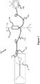
- the present invention is generally directed to a powered or automatic air management system 100, as seen in Figure 1 , for measuring pressure from an air pressure catheter 101 located within a patient 10. While prior art air management systems, such as those in U.S. Pat. No. 8,360,988 , require a user to manually charge the pressure system with a known volume of air (i.e., by moving a piston by hand), the present embodiment includes powered pumps to automatically adjust the air volume to a desired level.
- the present embodiment includes a pressure transducer assembly 102 that is located at the bed of the patient and a separate pump assembly 104 that is fixed to an IV pole 12 that is away from the patient (e.g., 6 feet) and connected to a pressure monitor 106 (e.g., 10 feet maximum from the patient) to display the pressure readings.
- a pressure transducer assembly 102 that is located at the bed of the patient and a separate pump assembly 104 that is fixed to an IV pole 12 that is away from the patient (e.g., 6 feet) and connected to a pressure monitor 106 (e.g., 10 feet maximum from the patient) to display the pressure readings.
- the present automatic air management system 100 can be used in connection with measuring pressure at any location within a human body, it is especially useful for measuring intracranial pressure (ICP), which is often measured in connection with treatment of traumatic brain injury.
- ICP intracranial pressure
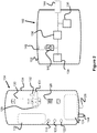
- the pump assembly 104 and the pressure transducer assembly 102 are illustrated in Figure 2 (general overview) and Figure 3 (schematic view of the system's air passage).
- the air passage of the system is represented by the connecting lines in Figure 3 , of which various components are connected.
- the pump assembly 104 includes two solenoid pumps 128 and 130 (e.g., 50 ⁇ L pumps) connected to the passage, as well as a pump assembly valve 131 and a filter 132.
- the valve 131 opens or closes the passage from opening to the atmosphere through the filter 132, while the pumps 128 and 130 are connected to the air passage on the opposite side of the valve 131.
- the air passage further connects to the pump connector socket 126, which contains pneumatic and electrical connections that connect to the transducer assembly cable 110.
- Cables 110A are an electrical conduit that provide power from the pump assembly 104 to the pressure transducer assembly 102
- Cables 110B transmit the pressure signal from the pressure transducer 136 to the pump assembly 104
- cables 110C provide power from the pump assembly 104 to the valve 138
- pneumatic conduit 110D provides a pneumatic connection from the pump assembly 104 to the pressure transducer assembly 102.
- the transducer assembly cable 110 connects to the transducer assembly 102 via connector 134.
- the air passage initially splits off to connect to a check valve 140 that vents to atmosphere via filter 142.
- the passage also connects to a valve 138 that opens or closes the air passage at that location.
- the air passage connects to a pressure transducer 136 and to the catheter connector 144.
- the air catheter 101 connects to the connector 144, allowing the air passage to connect to the air passage and air bladder within the catheter 101.
- the operation of the components of both the pressure transducer assembly 102 and the pump assembly 104 are preferably controller by a control assembly, which are preferably components on a printed circuit board 112.
- the printed circuit board 112 may include a microprocessor that executes firmware and/or software stored in a memory that, when executed, performs the functions described in this specification.
- the circuit board 112 may also be connected to "zero monitor" button 118 to allow a user to zero out the pressure signal to the monitor 106, a "prime system” button 120 that allows a user to inject the desired amount of air into the system, and a “stop” button 24 that allows a user to stop the pump assembly 104. While not shown in Figures 2 and 3 , an alarm LED and an "alarm pause" button can also be included, which indicate a problem with the system and provide a mechanism to stop the alarm, respectively, in such a situation.
- the circuit board 112 is connected to monitor connector socket 144 that connects with the pressure monitor cord 108 so as to communicate with the monitor 106 (e.g., via one of the electrical conduits 108A or 108B in Fig. 5 ), to a battery 124 via connector 116 to power the system, to the solenoid pumps 128 and 130, the valves 138, and to the transducer 136, to control pressure within the system and provide pressure measurement, respectively.
- the patient monitor excitation on these conduits wakes up the system 100 for operation and sends voltage to the pressure transducer assembly 102 and receives the pressure signal from the transducer assembly 102.
- the automatic air management system 100 and the catheter 101 must have, not only a known amount of air, but an amount that does not over or under inflate the air bladder of the catheter 101. For example, if the system is over inflated, the resulting pressure readings will be greater than the pressure external to the catheter within the patient's body (e.g., intracranial pressure). If the system is under inflated, the pressure within the catheter 101 will read less than that within the patient's body, especially with high pressures in the patient.
- the pressure within the system 100 is maintained via three main pump cycles.
- the first is the evacuation cycle in which the valve 138 is opened and the solenoid pumps 128 and 130 displace volume within the air passage (e.g., by 100 ⁇ L), thereby pulling residual air from the air passage of the catheter 101.
- the valve 138 is then closed, sealing off the air passage within the catheter 101.
- the second cycle is the injection cycle, in which the valve 138 is again opened and the solenoid pumps 128 and 130 are again actuated to displace volume within the air passage (e.g., by 100 ⁇ L), thereby pulling more residual air from the air passage of the catheter 101. This lowers the pressure within the air passage to a negative pressure equal to the crack pressure of the check valve 140 (e.g., 4kPa).
- the solenoid pumps 128 and 130 again displace volume so as to decrease the system volume (e.g., by 100 ⁇ L), thereby increasing the amount of air in the catheter 101.
- the third cycle is the air optimization cycle, in which a decision point occurs. If the pressure is above a predetermined level (e.g., 40-60mmHg or greater), the valve 138 closes. If the pressure is less than a predetermined level (e.g., 40-60mmHg or less), one of the solenoid pumps 128 or 130 displaces volume (e.g., by 50 ⁇ L), increasing the system volume, and removing air from the system. The valve 138 then closes and there pressure transducer 136 begins monitoring the pressure.
- a predetermined level e.g. 40-60mmHg or greater
- having two solenoid pumps 128 and 130 allows more granularity when inflating and deflating the air bladder of the catheter 101. This can allows the system to better compensate for dilating in low pressure environments or high pressure environments without adding or extracting excessive volumes of air. Hence, the optimal amount of air can be present within the bladder of the catheter 101 at any pressure.
- the software executed by the microprocessor can detect connection and disconnection of the catheter 101 from the pressure transducer assembly 102. For example, if the transducer 136 detects a positive pressure spike, the catheter may have been recently connected. If the transducer 136 detects a negative pressure spike, the catheter may have been disconnected. This detection may also result in an indicator on either the pump assembly 104 or the transducer assembly 102 indicating either state to the user (e.g., via a changing color or flashing of an LED). Alternately, the catheter detection can be achieved by an optical sensor, mechanical switch, or an electromechanical sensor (e.g., a Halls-effect sensor).
- FIGS 6A-23 illustrate various aspects of another embodiment of an automatic air management system 180 that is generally similar to the previously described embodiment 100.
- the pump assembly 104 includes a user interface 146, a monitor connector 144, and a transducer assembly connector 126. This pump assembly 104 can be fixed to and removed from an I.V. pole 12.
- Figure 6B illustrates an enlarged view of the user interface 146 that indicates and performs various functions and aspects of the system 180.
- a "Zero Monitor” LED indicator and button causes the pump to zero out the monitor 106 prior to use, ensuring an accurate pressure will be displayed.
- a "Connect Catheter” LED indicator indicates whether the catheter 101 is connected to the pressure transducer assembly 102. This connection status can be sensed via a pressure measurement (e.g., the pressure is equal to the outside atmosphere) or via a mechanical mechanism on the transducer assembly 102 (e.g., a button or switch).
- a "Prime System” LED indicator and button allows the user to activate the pump assembly 104 to inject the desired amount of air into the air passage and catheter 101, so that pressure measurement can take place.
- a battery indicator is also shown, indicating an estimated battery level (e.g., via a plurality of vertical LEDs).
- an "Alarm” LED indicator and “Alarm Pause” button indicate to the user that problem exists with the system, such as the pressure measurement is out of normal range or that the battery is critically low, and that such an alarm can be temporarily paused.
- a “Stop” button stops operation of the pump assembly 104.
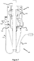
- Figures 7 and 8 illustrate a back and top view of the pump assembly 104, including two pivoting clamp members 150 that engage the I.V. pole, locking the pump assembly 104 in place.
- the back area of the pump assembly 104 and each of the clamp members 150 are curved so as to accommodate the diameter of the pole 12.
- the clamp members 150 can be biased to a closed state (e.g., with springs as seen in Figure 10 ) and/or can be lockable in position to prevent the pump assembly 104 from falling off.
- the clamp members 150 preferably have a relatively soft, elastomer layer that faces the IV pole 12, thereby increasing the friction with the pole.
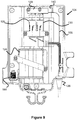
- Figure 9 illustrates a side view of the interior of the pump assembly 104 and Figure 10 illustrates an exploded view of the assembly 104.
- the components of the pump assembly 104 are all contained within a front enclosure 104A and a back enclosure 104B.
- the circuit board 112 abuts the front enclosure 104A and preferably includes the button mechanisms and LEDs that are seen on the front user interface 146.
- the battery enclosure 124 that contains one or more batteries to power the pump assembly 104.
- a pair of wires that connect to the circuit board 112, providing it power.
- solenoid pumps 128 and 130 e.g., 50 ⁇ L or 65 ⁇ L pumps
- the ports of the pumps 128, 130 both connect to a first internal manifold passage that connects to both the main air passage of the system (i.e., the passage connecting to the catheter 101) and to the output filter 142.
- a valve 160 opens or closes this first internal manifold passage to the filter 142 and therefore to the atmosphere within the pump assembly 104, thereby allowing the pumps to selectively discharge air to the atmosphere.
- the pump manifold also includes a second internal manifold passage that is connected to an air intake passage to the transducer assembly 102 (described later in this specification) and to the input filter 140, which allows air to flow from the pump assembly 104 to the transducer assembly 102.
- the circuit board 112 is connected via wires to the pumps 128, 130 to allow for their actuation, to the transducer assembly connector 144 to provide power and receive the transducer data, and to monitor connector 126 to provide pressure data to the monitor.
- Figure 13 illustrates an example air pressure catheter 101 having an air bladder 101A, a catheter tube 101B with an internal air passage, and a connector assembly 101C that connects with the connector assembly 152 of the transducer assembly 102.
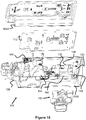
- Figures 14-19 illustrates various aspects of the pressure transducer assembly 102.
- the assembly 102 includes an indicator 160 which includes one or more LEDs that indicate if the catheter 101 is properly connected.
- the connector assembly 152 includes a biased latching mechanism 152B that maintains the catheter's connector assembly 101C in a locked configuration.
- a removable protective cover 152A is located over the latch 152B, thereby protecting from accidental disconnection of the catheter 101. Additional details of the connection mechanism can be found in U.S. Pat. No. 14/643,997 , the contents of which are incorporated herein by reference.
- the air passage of the catheter 101 continues through the passage 154 of the manifold 156, downwards, then up into a bottom port of the pressure transducer 158.
- the diameter of the passage 154 is small, such as 0.0020", to help minimize the amount of the air passage volume and therefore provide optimal air volume within the catheter bladder at different external pressures and thereby offering more accurate pressure readings.
- the passage within the transducer 158 then further connects with solenoid valve 162, which either closes off the tranducer's passage during operation, or opens up the passage during priming.
- the solenoid valve 162 is then connected to a manifold passage 156A within the manifold 156, best seen in Figure 19 .
- the passage 156A has two ports 156B and a check valve 166. One of the ports 156B is connected to the solenoid valve 162, while the other is connected to the pneumatic conduit in the cable 110 that leads to the pump assembly 104. In this respect, the passage 156A provides communication with the main air passage and the check valve 166.
- the check valve 166 When the check valve 166 is caused to be opened (e.g., at a predetermined negative pressure), it takes in air from within area 164. Area 164 is in communication with intake passage 168, which connects to the second passage in the pump manifold 129, which ultimately leads to the input filter 140. Hence, the area 164 is in communication with the atmosphere, allowing the check valve 166 to intake air.
- a plurality of electrical wires are also connected within the transducer assembly 102 for powering the valve 162, powering and communicating with the transducer 158, and powering the indicator 160.
- Figure 20 illustrates another view of the pressure transducer assembly 102 and cable 110.
- Figure 21 illustrates another view of the monitor cable 108.
- Figure 22 illustrates a flow chart for priming the previously discussed system 180.
- step 200 the system vents to atmosphere.
- valve 162 and valve 160 are both opened, allowing the entire main air passage to equalize with the atmospheric pressure.
- step 202 evacuation occurs. First, valve 160 is closed (valve 162 remains open). Next, solenoid pumps 128, 130 are activated so as to increase the overall volume in the system (i.e., suck out some of the air from the main air passage). Finally, valve 162 is closed, isolating the passage 154 and the passage within the catheter 101.
- step 204 recharging occurs.
- valve 160 is opened and the pumps 128, 130 are activated so as to decrease the overall volume, pushing air out via fileter142. Valve 160 is then closed to seal off the main air passage.
- step 206 evacuation occurs again.
- valve 160 is closed (valve 162 remains open).
- solenoid pumps 128, 130 are activated so as to increase the overall volume in the system (i.e., suck out some of the air from the main air passage).
- valve 162 is closed, isolating the passage 154 and the passage within the catheter 101. If the negative air pressure in the main air pressure passage exceeds the crack pressure of the check valve 166 (such as a pressure between 40-60mmHg), the check valve 166 will open, taking in air from area 164, until the air pressure within the main air passage reaches that crack pressure and the valve 166 closes. At this time, the pump assembly 104 monitors the pressure in the main air passage to determine if it indeed reached the desired level of the crack pressure of the valve. If not, the evacuation step is performed again.
- valve 160 is opened (valve 162 remains closed) while only solenoid pump 128 is activated so as to increase the overall volume in the main air passage.
- valve 160 is closed, closing off communication with the input filter 142.
- step 210 a single pump injection is performed.
- valve 162 is opened, allowing access to passage 154 and to the air passage of the catheter 101.
- the pump 128 is activated so as to decrease the volume in the main air passage, thereby injecting additional air into the system.
- the valve 162 is closed, isolating the transducer 158, the passage 154, and the passage within the catheter 101.
- the volume of air and pressure in the passage is known.
- the pressure within the patient e.g., within the cranium of the patient
Abstract
Description
- This application claims priority to
U.S. Provisional Application Serial No. 62/009,874 filed June 9, 2014 - Presently, biologically compatible air-based pressure monitoring catheters are used in a number of medical applications to monitor pressure at various locations within a mammalian body. For example, air-based pressure monitoring catheters may be inserted into the skull of a patient thereby permitting the external monitoring of intra-cranial pressure.
- Currently, a number of air-based pressure monitoring catheters have been developed. Generally, these air-based pressure monitoring catheters comprise a catheter having an air lumen formed therein which communicates with a bladder positioned at or near its distal end. In addition, the catheter includes a connector located at or near its proximal end which may be connected to an external pressure transducer. During use, the volume of the bladder attached to the catheter changes as pressure varies in accordance with Boyle's Law (P1V1=P2V2). As a result, the pressure of the gas within the catheter becomes equal to that of the environment surrounding the bladder. The media surrounding the bladder must be capable of movement to accommodate the variations in bladder volume as pressure changes.
- The use of air-based pressure monitoring catheters in low or negatively pressurized environments has proven problematic. When the proximal connector is open to atmospheric pressure in the process of periodically replacing air lost by diffusion through the bladder, the external pressure extant in the body site monitored on a bladder will expel residual air from the bladder. If the pressure is low or negative, a significant amount of residual air may remain in the bladder. The amount of air injected is intended to be sufficient to keep the bladder in an active state. If this volume is added to the residual air in a bladder that has not been completely collapsed by the environment around it, the sum of the residual air and injected air exceed the intrinsic volume of a fully shaped bladder. Should this happen, a positive pressure is established in the bladder. The bladder is now unable to read pressure below the internal pressure created.
- Air management systems such as those seen in
U.S. Pub. No. 2007/0208270 ,U.S. Pat. No. 6,447,462 ,U.S. Pat. No. 8,876,729 , andU.S. Pat. No. 8,360,988 which are all herein incorporated by reference, allow a user to adjust the amount of air in a system. For example, these systems allow a user to vent the air passage of the catheter to the open environment, then charge the passage with an amount of air. This allows a proper, known volume of air to be located in the system, thereby allowing the system to accurately calculate pressure within a patient's body. - One embodiment is generally directed to a powered or automatic air management system for measuring pressure from an air pressure catheter located within a patient. While prior art air management systems, such as those in
U.S. Pat. No. 8,360,988 , require a user to manually charge the pressure system with a known volume of air (i.e., by moving a piston by hand), the present embodiment includes powered pumps to automatically adjust the air volume to a desired level. Additionally, while prior systems include the system's pressure transducer, manual pumps, and other components in a single enclosure, the present embodiment includes a pressure transducer assembly that is located at the bed of the patient and a separate pump assembly that is fixed to an IV pole away from the patient and connected to a pressure monitor to display the pressure readings. By locating the pressure transducer to a location relatively close to the connection point of the catheter, more accurate pressure readings can be achieved. Additionally, the weight of the pump mechanism is located on the IV pole, allowing the components near the patient to be relatively lightweight. - These and other aspects, features and advantages of which embodiments of the invention are capable of will be apparent and elucidated from the following description of embodiments of the present invention, reference being made to the accompanying drawings, in which:
-
Fig. 1 is an overview of an automatic air management system for pressure measurement with an air catheter. -
Figs. 2 and3 illustrate a pump assembly and a pressure transducer assembly of the system ofFig. 1 . -
Fig. 4 illustrates a cross section of a pressure transducer assembly cable. -
Fig. 5 illustrates a cross section of a pressure monitor cable. -
Fig. 6A-8 illustrate various aspects of an exterior of another embodiment of a pump assembly. -
Figs. 9 and10 illustrate an interior of the pump assembly ofFig. 6A . -
Figs. 11 and 12 illustrate a pump manifold and pumps fromFig. 9 . -
Fig. 13 illustrates an air catheter. -
Figs. 14 and 15 illustrate an outside view of a pressure transducer assembly. -
Figs. 16-19 illustrate various views of an interior of the pressure transducer assembly ofFig. 14 . -
Fig. 20 illustrates a pressure transducer assembly and pressure transducer assembly cable. -
Fig. 21 illustrates a pressure monitor cable. -
Fig. 22 illustrates a flow chart describing the process of priming the system with a specific amount of air. - Specific embodiments of the invention will now be described with reference to the accompanying drawings. This invention may, however, be embodied in many different forms and should not be construed as limited to the embodiments set forth herein; rather, these embodiments are provided so that this disclosure will be thorough and complete, and will fully convey the scope of the invention to those skilled in the art. The terminology used in the detailed description of the embodiments illustrated in the accompanying drawings is not intended to be limiting of the invention. In the drawings, like numbers refer to like elements.
- The present invention is generally directed to a powered or automatic
air management system 100, as seen inFigure 1 , for measuring pressure from anair pressure catheter 101 located within apatient 10. While prior art air management systems, such as those inU.S. Pat. No. 8,360,988 , require a user to manually charge the pressure system with a known volume of air (i.e., by moving a piston by hand), the present embodiment includes powered pumps to automatically adjust the air volume to a desired level. Additionally, while prior systems include the system's pressure transducer, manual pumps, and other components in a single enclosure, the present embodiment includes apressure transducer assembly 102 that is located at the bed of the patient and aseparate pump assembly 104 that is fixed to an IVpole 12 that is away from the patient (e.g., 6 feet) and connected to a pressure monitor 106 (e.g., 10 feet maximum from the patient) to display the pressure readings. By locating the pressure transducer to a location relatively close to the connection point of the catheter, more accurate pressure readings can be achieved. - It should be noted that the present automatic
air management system 100 can be used in connection with measuring pressure at any location within a human body, it is especially useful for measuring intracranial pressure (ICP), which is often measured in connection with treatment of traumatic brain injury. - One embodiment of the
pump assembly 104 and thepressure transducer assembly 102 are illustrated inFigure 2 (general overview) andFigure 3 (schematic view of the system's air passage). The air passage of the system is represented by the connecting lines inFigure 3 , of which various components are connected. Thepump assembly 104 includes twosolenoid pumps 128 and 130 (e.g., 50µL pumps) connected to the passage, as well as apump assembly valve 131 and afilter 132. Thevalve 131 opens or closes the passage from opening to the atmosphere through thefilter 132, while thepumps valve 131. - The air passage further connects to the
pump connector socket 126, which contains pneumatic and electrical connections that connect to thetransducer assembly cable 110. One specific example of the layout of thetransducer assembly cable 110 can be seen inFigure 4 .Cables 110A are an electrical conduit that provide power from thepump assembly 104 to thepressure transducer assembly 102,Cables 110B transmit the pressure signal from thepressure transducer 136 to thepump assembly 104,cables 110C provide power from thepump assembly 104 to thevalve 138, andpneumatic conduit 110D provides a pneumatic connection from thepump assembly 104 to thepressure transducer assembly 102. - The
transducer assembly cable 110 connects to thetransducer assembly 102 viaconnector 134. As seen inFigure 2 and3 , the air passage initially splits off to connect to acheck valve 140 that vents to atmosphere viafilter 142. The passage also connects to avalve 138 that opens or closes the air passage at that location. On the other side of thevalve 138, the air passage connects to apressure transducer 136 and to thecatheter connector 144. Finally theair catheter 101 connects to theconnector 144, allowing the air passage to connect to the air passage and air bladder within thecatheter 101. - The operation of the components of both the
pressure transducer assembly 102 and thepump assembly 104 are preferably controller by a control assembly, which are preferably components on a printedcircuit board 112. For example, the printedcircuit board 112 may include a microprocessor that executes firmware and/or software stored in a memory that, when executed, performs the functions described in this specification. Thecircuit board 112 may also be connected to "zero monitor"button 118 to allow a user to zero out the pressure signal to themonitor 106, a "prime system"button 120 that allows a user to inject the desired amount of air into the system, and a "stop" button 24 that allows a user to stop thepump assembly 104. While not shown inFigures 2 and3 , an alarm LED and an "alarm pause" button can also be included, which indicate a problem with the system and provide a mechanism to stop the alarm, respectively, in such a situation. - Further, the
circuit board 112 is connected to monitorconnector socket 144 that connects with thepressure monitor cord 108 so as to communicate with the monitor 106 (e.g., via one of theelectrical conduits Fig. 5 ), to abattery 124 via connector 116 to power the system, to the solenoid pumps 128 and 130, thevalves 138, and to thetransducer 136, to control pressure within the system and provide pressure measurement, respectively. With regard to theelectrical conduits system 100 for operation and sends voltage to thepressure transducer assembly 102 and receives the pressure signal from thetransducer assembly 102. - It should be noted that the automatic
air management system 100 and thecatheter 101 must have, not only a known amount of air, but an amount that does not over or under inflate the air bladder of thecatheter 101. For example, if the system is over inflated, the resulting pressure readings will be greater than the pressure external to the catheter within the patient's body (e.g., intracranial pressure). If the system is under inflated, the pressure within thecatheter 101 will read less than that within the patient's body, especially with high pressures in the patient. - In the present embodiment, the pressure within the
system 100 is maintained via three main pump cycles. The first is the evacuation cycle in which thevalve 138 is opened and the solenoid pumps 128 and 130 displace volume within the air passage (e.g., by 100 µL), thereby pulling residual air from the air passage of thecatheter 101. Thevalve 138 is then closed, sealing off the air passage within thecatheter 101. - The second cycle is the injection cycle, in which the
valve 138 is again opened and the solenoid pumps 128 and 130 are again actuated to displace volume within the air passage (e.g., by 100 µL), thereby pulling more residual air from the air passage of thecatheter 101. This lowers the pressure within the air passage to a negative pressure equal to the crack pressure of the check valve 140 (e.g., 4kPa). Next, the solenoid pumps 128 and 130 again displace volume so as to decrease the system volume (e.g., by 100 µL), thereby increasing the amount of air in thecatheter 101. - The third cycle is the air optimization cycle, in which a decision point occurs. If the pressure is above a predetermined level (e.g., 40-60mmHg or greater), the
valve 138 closes. If the pressure is less than a predetermined level (e.g., 40-60mmHg or less), one of the solenoid pumps 128 or 130 displaces volume (e.g., by 50 µL), increasing the system volume, and removing air from the system. Thevalve 138 then closes and therepressure transducer 136 begins monitoring the pressure. - As seen with regard to the air optimization cycle described above, having two
solenoid pumps catheter 101. This can allows the system to better compensate for dilating in low pressure environments or high pressure environments without adding or extracting excessive volumes of air. Hence, the optimal amount of air can be present within the bladder of thecatheter 101 at any pressure. - In another aspect of the present invention, the software executed by the microprocessor can detect connection and disconnection of the
catheter 101 from thepressure transducer assembly 102. For example, if thetransducer 136 detects a positive pressure spike, the catheter may have been recently connected. If thetransducer 136 detects a negative pressure spike, the catheter may have been disconnected. This detection may also result in an indicator on either thepump assembly 104 or thetransducer assembly 102 indicating either state to the user (e.g., via a changing color or flashing of an LED). Alternately, the catheter detection can be achieved by an optical sensor, mechanical switch, or an electromechanical sensor (e.g., a Halls-effect sensor). -
Figures 6A-23 illustrate various aspects of another embodiment of an automaticair management system 180 that is generally similar to the previously describedembodiment 100. Turning first toFigure 6A and6B , thepump assembly 104 includes auser interface 146, amonitor connector 144, and atransducer assembly connector 126. Thispump assembly 104 can be fixed to and removed from an I.V.pole 12. -
Figure 6B illustrates an enlarged view of theuser interface 146 that indicates and performs various functions and aspects of thesystem 180. Specifically, a "Zero Monitor" LED indicator and button causes the pump to zero out themonitor 106 prior to use, ensuring an accurate pressure will be displayed. Next, a "Connect Catheter" LED indicator indicates whether thecatheter 101 is connected to thepressure transducer assembly 102. This connection status can be sensed via a pressure measurement (e.g., the pressure is equal to the outside atmosphere) or via a mechanical mechanism on the transducer assembly 102 (e.g., a button or switch). A "Prime System" LED indicator and button allows the user to activate thepump assembly 104 to inject the desired amount of air into the air passage andcatheter 101, so that pressure measurement can take place. A battery indicator is also shown, indicating an estimated battery level (e.g., via a plurality of vertical LEDs). Next, an "Alarm" LED indicator and "Alarm Pause" button indicate to the user that problem exists with the system, such as the pressure measurement is out of normal range or that the battery is critically low, and that such an alarm can be temporarily paused. Finally, a "Stop" button stops operation of thepump assembly 104. -
Figures 7 and8 illustrate a back and top view of thepump assembly 104, including two pivotingclamp members 150 that engage the I.V. pole, locking thepump assembly 104 in place. Preferably, the back area of thepump assembly 104 and each of theclamp members 150 are curved so as to accommodate the diameter of thepole 12. Theclamp members 150 can be biased to a closed state (e.g., with springs as seen inFigure 10 ) and/or can be lockable in position to prevent thepump assembly 104 from falling off. Theclamp members 150 preferably have a relatively soft, elastomer layer that faces theIV pole 12, thereby increasing the friction with the pole. -
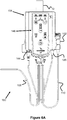
Figure 9 illustrates a side view of the interior of thepump assembly 104 andFigure 10 illustrates an exploded view of theassembly 104. The components of thepump assembly 104 are all contained within afront enclosure 104A and aback enclosure 104B. Thecircuit board 112 abuts thefront enclosure 104A and preferably includes the button mechanisms and LEDs that are seen on thefront user interface 146. - Beneath the
circuit board 112, at the lower portion of thepump assembly 104 is thebattery enclosure 124 that contains one or more batteries to power thepump assembly 104. Near the lower end of theenclosure 124 is a pair of wires that connect to thecircuit board 112, providing it power. - Beneath the
circuit board 112, at the upper portion of thepump assembly 104 aresolenoid pumps 128 and 130 (e.g., 50 µL or 65 µL pumps), which are connected to apump manifold 129.Figures 11 and 12 illustrate these components in greater detail. The ports of thepumps output filter 142. Avalve 160 opens or closes this first internal manifold passage to thefilter 142 and therefore to the atmosphere within thepump assembly 104, thereby allowing the pumps to selectively discharge air to the atmosphere. The pump manifold also includes a second internal manifold passage that is connected to an air intake passage to the transducer assembly 102 (described later in this specification) and to theinput filter 140, which allows air to flow from thepump assembly 104 to thetransducer assembly 102. - As best seen in
Figure 10 , thecircuit board 112 is connected via wires to thepumps transducer assembly connector 144 to provide power and receive the transducer data, and to monitorconnector 126 to provide pressure data to the monitor. -
Figure 13 illustrates an exampleair pressure catheter 101 having anair bladder 101A, acatheter tube 101B with an internal air passage, and aconnector assembly 101C that connects with theconnector assembly 152 of thetransducer assembly 102. -
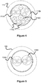
Figures 14-19 illustrates various aspects of thepressure transducer assembly 102. As seen inFigure 15 , theassembly 102 includes anindicator 160 which includes one or more LEDs that indicate if thecatheter 101 is properly connected. As seen best inFigures 16 and 17 , theconnector assembly 152 includes abiased latching mechanism 152B that maintains the catheter'sconnector assembly 101C in a locked configuration. A removableprotective cover 152A is located over thelatch 152B, thereby protecting from accidental disconnection of thecatheter 101. Additional details of the connection mechanism can be found inU.S. Pat. No. 14/643,997 - As best seen in
Figures 16-18 , the air passage of thecatheter 101 continues through thepassage 154 of the manifold 156, downwards, then up into a bottom port of thepressure transducer 158. Preferably, the diameter of thepassage 154 is small, such as 0.0020", to help minimize the amount of the air passage volume and therefore provide optimal air volume within the catheter bladder at different external pressures and thereby offering more accurate pressure readings. - The passage within the
transducer 158 then further connects withsolenoid valve 162, which either closes off the tranducer's passage during operation, or opens up the passage during priming. Thesolenoid valve 162 is then connected to amanifold passage 156A within themanifold 156, best seen inFigure 19 . Thepassage 156A has twoports 156B and acheck valve 166. One of theports 156B is connected to thesolenoid valve 162, while the other is connected to the pneumatic conduit in thecable 110 that leads to thepump assembly 104. In this respect, thepassage 156A provides communication with the main air passage and thecheck valve 166. - When the
check valve 166 is caused to be opened (e.g., at a predetermined negative pressure), it takes in air from withinarea 164.Area 164 is in communication withintake passage 168, which connects to the second passage in thepump manifold 129, which ultimately leads to theinput filter 140. Hence, thearea 164 is in communication with the atmosphere, allowing thecheck valve 166 to intake air. - As best seen in
Figure 18 , in addition to the main air passage and the air intake passage, a plurality of electrical wires are also connected within thetransducer assembly 102 for powering thevalve 162, powering and communicating with thetransducer 158, and powering theindicator 160. -
Figure 20 illustrates another view of thepressure transducer assembly 102 andcable 110.Figure 21 illustrates another view of themonitor cable 108. -
Figure 22 illustrates a flow chart for priming the previously discussedsystem 180. Instep 200, the system vents to atmosphere. Specifically,valve 162 andvalve 160 are both opened, allowing the entire main air passage to equalize with the atmospheric pressure. - In
step 202, evacuation occurs. First,valve 160 is closed (valve 162 remains open). Next, solenoid pumps 128, 130 are activated so as to increase the overall volume in the system (i.e., suck out some of the air from the main air passage). Finally,valve 162 is closed, isolating thepassage 154 and the passage within thecatheter 101. - In
step 204, recharging occurs. First,valve 160 is opened and thepumps Valve 160 is then closed to seal off the main air passage. - In
step 206, evacuation occurs again. First,valve 160 is closed (valve 162 remains open). Next, solenoid pumps 128, 130 are activated so as to increase the overall volume in the system (i.e., suck out some of the air from the main air passage). Finally,valve 162 is closed, isolating thepassage 154 and the passage within thecatheter 101. If the negative air pressure in the main air pressure passage exceeds the crack pressure of the check valve 166 (such as a pressure between 40-60mmHg), thecheck valve 166 will open, taking in air fromarea 164, until the air pressure within the main air passage reaches that crack pressure and thevalve 166 closes. At this time, thepump assembly 104 monitors the pressure in the main air passage to determine if it indeed reached the desired level of the crack pressure of the valve. If not, the evacuation step is performed again. - Once the desired pressure has been achieved (i.e., the crack pressure of check valve 166), a partial system volume to
atmosphere step 208 is performed.Valve 160 is opened (valve 162 remains closed) whileonly solenoid pump 128 is activated so as to increase the overall volume in the main air passage. Next,valve 160 is closed, closing off communication with theinput filter 142. - In
step 210, a single pump injection is performed. First,valve 162 is opened, allowing access topassage 154 and to the air passage of thecatheter 101. Next, thepump 128 is activated so as to decrease the volume in the main air passage, thereby injecting additional air into the system. - Finally, in the
run mode step 212, thevalve 162 is closed, isolating thetransducer 158, thepassage 154, and the passage within thecatheter 101. At this time, the volume of air and pressure in the passage is known. As the pressure within the patient (e.g., within the cranium of the patient) pushes on theflexible bladder 101A of thecatheter 101, the pressure within the patient can also be calculated according to Boyle's Law (P1V1=P2V2). - Although the invention has been described in terms of particular embodiments and applications, one of ordinary skill in the art, in light of this teaching, can generate additional embodiments and modifications without departing from the spirit of or exceeding the scope of the claimed invention. Accordingly, it is to be understood that the drawings and descriptions herein are proffered by way of example to facilitate comprehension of the invention and should not be construed to limit the scope thereof.
-
- 1. An automatic air pressure management system for monitoring pressure within a patient with an air catheter, comprising:
- a pump assembly enclosure comprising an air pump mechanism; a control assembly; and a pressure monitor connector;
- a pressure transducer assembly enclosure comprising a pressure transducer and an air catheter connection mechanism that releasably connects to an air catheter; and,
- a pressure transducer assembly cable connecting said pump assembly enclosure with said pressure transducer assembly enclosure.
- 2. The automatic air pressure management system of
embodiment 1, further comprising a first valve located within said pressure transducer assembly enclosure; said first valve selectively blocking pneumatic communication with said pump assembly. - 3. The automatic air pressure management system of
embodiment 1, further comprising a first valve located in said pump assembly enclosure; said first valve selectively blocking pneumatic communication with the atmosphere. - 4. The automatic air pressure management system of
embodiment 1, further comprising a check valve located in said pressure transducer assembly enclosure and allowing air to enter an air catheter above a predetermined negative pressure within said air catheter. - 5. The automatic air pressure management system of
embodiment 1, further comprising a clamp mechanism locate on said pump assembly enclosure and configured to clamp onto an I.V. pole. - 6. The automatic air pressure management system of
embodiment 1, wherein air pump mechanism comprises two separately activated pumps. - 7. The automatic air pressure management system of
embodiment 1, wherein said control assembly includes software configured to cause said pump assembly enclosure to:- vent to the atmosphere;
- evacuate an air passage of said automatic air pressure management system;
- recharge an air passage of said automatic air pressure management system; and,
- perform a single pump injection of said automatic air pressure management system.
- 8. An automatic air pressure management system for monitoring pressure within a patient with an air catheter, comprising:
- a pump assembly enclosure comprising an air pump mechanism; and a control assembly;
- a pressure transducer assembly enclosure comprising a pressure transducer and an air catheter connection mechanism that releasably connects to an air catheter; and,
- a pressure transducer assembly cable connecting said pump assembly enclosure with said pressure transducer assembly enclosure;
- wherein an air passage is created between said pump assembly enclosure, said pressure transducer assembly cable, and said pressure transducer assembly enclosure.
- 9. The automatic air pressure management system of embodiment 8, further comprising a first valve located within said pressure transducer assembly enclosure that selectively closes said air passage.
- 10. The automatic air pressure management system of embodiment 9, further comprising a second valve located in said pump assembly enclosure; said second valve selectively blocking pneumatic communication with the atmosphere.
- 11. The automatic air pressure management system of
embodiment 10, further comprising a check valve located in said pressure transducer assembly enclosure and allowing air to enter said air passage above a predetermined negative pressure within said air passage. - 12. The automatic air pressure management system of embodiment 11, wherein said air pump mechanism is in communication with said air passage and wherein said air pump mechanism are two separately activated pumps.
- 13. The automatic air pressure management system of
embodiment 12, wherein said control assembly includes software configured to cause said pump assembly enclosure to:- vent to the atmosphere;
- evacuate an air passage of said automatic air pressure management system;
- recharge an air passage of said automatic air pressure management system; and,
- perform a single pump injection of said automatic air pressure management system.
- 14. The automatic air pressure management system of embodiment 13, further comprising a clamp mechanism locate on said pump assembly enclosure and configured to clamp onto an I.V. pole.
- 15. The automatic air pressure management system of 14, further comprises an air intake passage extending between said pump assembly enclosure, through said pressure transducer assembly cable, to said pressure transducer assembly enclosure, and in communication with said check valve.
- 16. An automatic air pressure management system for monitoring pressure within a patient with an air catheter, comprising:
- a pump assembly enclosure comprising an air pump mechanism; and a control assembly;
- a pressure transducer assembly enclosure comprising a pressure transducer and an air catheter connection mechanism that releasably connects to an air catheter;
- a pressure transducer assembly cable connecting said pump assembly enclosure with said pressure transducer assembly enclosure;
- an air passage extending between said pump assembly enclosure, said pressure transducer assembly cable, and said pressure transducer assembly enclosure, so as to allow selective pneumatic communication between said air pump mechanism and an air catheter when attached to said air catheter connection mechanism.
- 17. The automatic air pressure management system of embodiment 16, further comprising a first valve located within said pressure transducer assembly enclosure; said first valve selectively blocking pneumatic communication through said air passage with said pump assembly.
- 18. The automatic air pressure management system of embodiment 16, further comprising a first valve located in said pump assembly enclosure; said first valve selectively blocking pneumatic communication with the atmosphere.
- 19. The automatic air pressure management system of embodiment 16, further comprising a check valve located in said pressure transducer assembly enclosure and allowing air to enter said air passage when a pressure within said air passage is greater than a crack pressure of said check valve.
Claims (8)
- An automatic air pressure management system for monitoring pressure within a patient with an air catheter, comprising:an air pump mechanism configured to pump air (128, 130);a control assembly (112);a pressure transducer (136);a first valve (131, 160) opening to the atmosphere outside of said automatic air pressure management system;an air catheter connection mechanism (144) that releasably connects to an air catheter;a common air passage in communication with said air pump mechanism, said pressure transducer, said first valve, and said air catheter connection mechanism; and,a second valve (132, 162) selectively isolating said pressure transducer and said air catheter connection mechanism from said air pump mechanism and said first valve within said common air passage;characterized in that:said control assembly is configured to:activate said pump mechanism to evacuate air from said common air passage with said first valve being closed and said second valve being open;close said second valve so as to isolate said pressure transducer and said air catheter connection mechanism;open said first valve to inject air into said common air passage;close said first valve; and,open said second valve to inject air to an air catheter attached to said air catheter connection mechanism to achieve a predetermined pressure.
- The automatic air pressure management system of claim 1, wherein said air pump mechanism, said control assembly, and said first valve are located in a pump assembly enclosure, and wherein said pressure transducer, said air catheter connection mechanism, and said second valve are located in a pressure transducer assembly enclosure.
- The automatic air pressure management system of claim 1, wherein said air pump mechanism further comprises a first pump and a second pump.
- The automatic air pressure management system of claim 1, wherein said control assembly is further configured to measure an air pressure with said pressure transducer.
- The automatic air pressure management system of claim 2, further comprising a pressure transducer assembly cable connecting said pump assembly enclosure with said pressure transducer assembly enclosure.
- The automatic air pressure management system of claim 1, wherein said control assembly is further configured to vent said common air passage, evacuate air from said common air passage by activating said pump mechanism, and open said first valve to allow air into said common air passage.
- The automatic air pressure management system of claim 1, further comprising a monitor connection socket (144) that is connectable with a pressure monitor cord (108) to a pressure monitor.
- The automatic air pressure management system of claim 1, further comprising a check valve connected to said common air passage and allowing air to enter said common air passage when a pressure within said common air passage is greater than a crack pressure of said check valve.
Applications Claiming Priority (3)
| Application Number | Priority Date | Filing Date | Title |
|---|---|---|---|
| US201462009874P | 2014-06-09 | 2014-06-09 | |
| EP15806745.4A EP3136957B1 (en) | 2014-06-09 | 2015-06-09 | Automatic air management system |
| PCT/US2015/034950 WO2015191618A1 (en) | 2014-06-09 | 2015-06-09 | Automatic air management system |
Related Parent Applications (1)
| Application Number | Title | Priority Date | Filing Date |
|---|---|---|---|
| EP15806745.4A Division EP3136957B1 (en) | 2014-06-09 | 2015-06-09 | Automatic air management system |
Publications (1)
| Publication Number | Publication Date |
|---|---|
| EP3443897A1 true EP3443897A1 (en) | 2019-02-20 |
Family
ID=54768604
Family Applications (2)
| Application Number | Title | Priority Date | Filing Date |
|---|---|---|---|
| EP15806745.4A Active EP3136957B1 (en) | 2014-06-09 | 2015-06-09 | Automatic air management system |
| EP18183645.3A Withdrawn EP3443897A1 (en) | 2014-06-09 | 2015-06-09 | Automatic air management system |
Family Applications Before (1)
| Application Number | Title | Priority Date | Filing Date |
|---|---|---|---|
| EP15806745.4A Active EP3136957B1 (en) | 2014-06-09 | 2015-06-09 | Automatic air management system |
Country Status (3)
| Country | Link |
|---|---|
| US (2) | US10687720B2 (en) |
| EP (2) | EP3136957B1 (en) |
| WO (1) | WO2015191618A1 (en) |
Families Citing this family (1)
| Publication number | Priority date | Publication date | Assignee | Title |
|---|---|---|---|---|
| CN112650786B (en) * | 2020-12-21 | 2022-11-01 | 河南德尔液空科技有限公司 | AI intelligent monitoring system of multi-zone air separation equipment |
Citations (6)
| Publication number | Priority date | Publication date | Assignee | Title |
|---|---|---|---|---|
| US6447462B1 (en) | 2000-02-15 | 2002-09-10 | Clinical Innovation Associates, Inc. | Urodynamic catheter and methods of fabrication and use |
| US20070208270A1 (en) | 2001-03-21 | 2007-09-06 | Bobo Donald E Sr | Gas Column Pressure Monitoring Device |
| US20080167607A1 (en) * | 2005-02-25 | 2008-07-10 | Ulrich Pfeiffer | Enteral Feeding Catheter, Computer System and Computer Program for Operating the Feeding Catheter |
| US20120041334A1 (en) * | 2009-04-09 | 2012-02-16 | Oliver Goedje | Device for measuring the bladder pressure |
| US8360988B2 (en) | 2008-10-24 | 2013-01-29 | Innerspace, Inc. | Catheter air management system |
| US20130231584A1 (en) * | 2010-07-09 | 2013-09-05 | Daniel Rogers Burnett | Method and apparatus for pressure measurement |
Family Cites Families (37)
| Publication number | Priority date | Publication date | Assignee | Title |
|---|---|---|---|---|
| US2866453A (en) | 1957-05-29 | 1958-12-30 | Warren R Jewett | Direct reading hypodermic pressure indicating device |
| GB968376A (en) | 1960-06-03 | 1964-09-02 | Robert Hans Muller Ph D | Improvements in catheters and the like and the manufacture thereof |
| US3122136A (en) * | 1961-06-16 | 1964-02-25 | Cordis Corp | Catheter pressure standard |
| US3662743A (en) | 1970-01-22 | 1972-05-16 | Corometrics Medical Systems In | Pressure transducer for catheter pressure measurement |
| US3719070A (en) | 1971-03-09 | 1973-03-06 | Vetco Offshore Ind Inc | Double sealed tubular connector apparatus |
| US3714869A (en) | 1971-03-26 | 1973-02-06 | Gen Motors Corp | Hydraulic power brake unit |
| US3884242A (en) | 1971-03-29 | 1975-05-20 | Mpc Kurgisil | Catheter assembly |
| US4077394A (en) | 1976-08-25 | 1978-03-07 | Mccurdy Martin D | Integral pressure sensor probe for a cardiac assistance device |
| US4301811A (en) | 1978-10-27 | 1981-11-24 | The Kendall Company | Cystometry system |
| US4776347A (en) | 1980-05-20 | 1988-10-11 | E. R. Squibb & Sons, Inc. | Device for devloping control of spincter-type muscles |
| US5562614A (en) | 1993-11-22 | 1996-10-08 | Advanced Cardiovascular Systems, Inc. | Programmable manifold system for automatic fluid delivery |
| US4714461A (en) | 1985-11-07 | 1987-12-22 | Becton, Dickinson And Company | Catheter assembly with air purging feature |
| US4934375A (en) | 1988-03-04 | 1990-06-19 | Spectramed, Inc. | Flush-valve assembly for blood pressure measurement catheter |
| US4903707A (en) | 1988-04-22 | 1990-02-27 | Camino Laboratories | Ventricular catheter assembly |
| DE3833723A1 (en) | 1988-10-04 | 1990-04-12 | Berg Extrakorp Syst Medtech | METHOD FOR ZERO COMPARISON OF A PRESSURE MEASURING CATHETER AND PRESSURE MEASURING CATHETER FOR ITS IMPLEMENTATION |
| EP0972535B1 (en) | 1991-09-12 | 2005-12-28 | Advanced Cardiovascular Systems, Inc. | Inflatable member having elastic expansion with limited range |
| US5810741A (en) | 1992-11-05 | 1998-09-22 | Synectics Medical Ab | Method of measuring respiration and respiratory effort using plural catheters |
| US5573007A (en) | 1994-08-08 | 1996-11-12 | Innerspace, Inc. | Gas column pressure monitoring catheters |
| US5644285A (en) | 1995-02-01 | 1997-07-01 | Honeywell Inc. | Pressure transducer with media isolation |
| US6099502A (en) | 1995-04-20 | 2000-08-08 | Acist Medical Systems, Inc. | Dual port syringe |
| US5951497A (en) | 1996-09-03 | 1999-09-14 | Clinical Innovation Associates, Inc. | Pressure catheter device with enhanced positioning features |
| US5984879A (en) | 1996-09-03 | 1999-11-16 | Clinical Innovation Associates, Inc. | Intrauterine pressure catheter device |
| FR2754701B1 (en) | 1996-10-18 | 1999-01-08 | Vermed | URETRAL COMPLIANCE MEASURING DEVICE |
| US5876376A (en) | 1996-12-09 | 1999-03-02 | Medtronic, Inc | Catheter balloon bonding stopper |
| US6056697A (en) * | 1997-09-29 | 2000-05-02 | The United States Of America As Represented By The Secretary Of The Air Force | Pressure catheter calibration chamber |
| TW376128U (en) * | 1998-04-29 | 1999-12-01 | Topeak Inc | Micro pressure reducing tools |
| ATE517574T1 (en) * | 2001-06-29 | 2011-08-15 | Ethicon Inc | SYSTEM FOR ASSESSING URINARY FUNCTION |
| US7780679B2 (en) | 2003-05-30 | 2010-08-24 | Innerspace Medical, Inc. | System and method for intracranial access and monitoring |
| CA2613983A1 (en) * | 2005-07-14 | 2007-02-15 | C.R. Bard, Inc. | Intra-abdominal pressure monitoring system |
| US20070060834A1 (en) * | 2005-08-23 | 2007-03-15 | Odland Rick M | Catheter control console |
| US10085677B2 (en) * | 2005-11-16 | 2018-10-02 | Etymotic Research, Inc. | System and method for performing a hearing screening |
| JP5019757B2 (en) * | 2006-02-10 | 2012-09-05 | 富士フイルム株式会社 | Balloon control device |
| EP1892010B1 (en) * | 2006-08-25 | 2010-10-06 | Pulsion Medical Systems AG | Enteral feeding catheter and apparatus for determining the intraabdominal pressure of a patient |
| BRPI0715035A2 (en) * | 2006-09-19 | 2013-05-28 | Kci Licensing Inc | medical device suspension apparatus and apparatus for the treatment of reduced pressure |
| US20110313394A1 (en) | 2008-10-24 | 2011-12-22 | Innerspace, Inc | Sensor Controlled Flow Path For Providing Fluids To Patients |
| US9707340B2 (en) | 2011-05-06 | 2017-07-18 | Zyno Medical Llc | Flow control line management apparatus |
| DE102013102085A1 (en) * | 2013-03-04 | 2014-09-04 | Andromeda Medizinische Systeme Gmbh | Device for measuring pressure in a fluid |
-
2015
- 2015-06-09 US US14/734,947 patent/US10687720B2/en active Active
- 2015-06-09 EP EP15806745.4A patent/EP3136957B1/en active Active
- 2015-06-09 EP EP18183645.3A patent/EP3443897A1/en not_active Withdrawn
- 2015-06-09 WO PCT/US2015/034950 patent/WO2015191618A1/en active Application Filing
-
2020
- 2020-05-18 US US16/877,392 patent/US20200275849A1/en not_active Abandoned
Patent Citations (8)
| Publication number | Priority date | Publication date | Assignee | Title |
|---|---|---|---|---|
| US6447462B1 (en) | 2000-02-15 | 2002-09-10 | Clinical Innovation Associates, Inc. | Urodynamic catheter and methods of fabrication and use |
| US20070208270A1 (en) | 2001-03-21 | 2007-09-06 | Bobo Donald E Sr | Gas Column Pressure Monitoring Device |
| US20080167607A1 (en) * | 2005-02-25 | 2008-07-10 | Ulrich Pfeiffer | Enteral Feeding Catheter, Computer System and Computer Program for Operating the Feeding Catheter |
| US8360988B2 (en) | 2008-10-24 | 2013-01-29 | Innerspace, Inc. | Catheter air management system |
| US20130345595A1 (en) * | 2008-10-24 | 2013-12-26 | Innerspace, Inc. | Catheter Air Management System |
| US8876729B2 (en) | 2008-10-24 | 2014-11-04 | InnerSpace Neuro Solutions, Inc. | Catheter air management system |
| US20120041334A1 (en) * | 2009-04-09 | 2012-02-16 | Oliver Goedje | Device for measuring the bladder pressure |
| US20130231584A1 (en) * | 2010-07-09 | 2013-09-05 | Daniel Rogers Burnett | Method and apparatus for pressure measurement |
Also Published As
| Publication number | Publication date |
|---|---|
| US20150351649A1 (en) | 2015-12-10 |
| EP3136957A4 (en) | 2017-05-17 |
| EP3136957B1 (en) | 2018-07-18 |
| US10687720B2 (en) | 2020-06-23 |
| EP3136957A1 (en) | 2017-03-08 |
| US20200275849A1 (en) | 2020-09-03 |
| WO2015191618A1 (en) | 2015-12-17 |
Similar Documents
| Publication | Publication Date | Title |
|---|---|---|
| US10265442B2 (en) | Devices and methods for managing chest drainage | |
| US10758135B2 (en) | Method and apparatus for pressure measurement | |
| EP2780068B1 (en) | Apparatus for preventing over inflation of the retention balloon in medical catheters and airway devices | |
| US8360988B2 (en) | Catheter air management system | |
| JP2002508195A (en) | Laparoscopic surgical access port with controlled sealing valve | |
| CN105025971A (en) | Inflation device for balloon sinus dilation | |
| US20140261442A1 (en) | Cuff pressure measurement device for a tracheal tube | |
| US20200275849A1 (en) | Automatic Air Management System | |
| WO2011100310A3 (en) | Deflation indicator for a medical device bolster | |
| IL259351A (en) | Colostomy balloon plug | |
| US20140343409A1 (en) | Inflation apparatus with pressure relief, related systems, methods and kits | |
| CA2480956C (en) | Single use catheter | |
| CN204723542U (en) | A kind of internal medicine nursing first aid respirator device | |
| CN209789946U (en) | Automatic change pressure hemostasis device | |
| CN207950291U (en) | One kind automatically controlling double sacculus casing incision cannulas | |
| CN216934349U (en) | Laryngeal mask system capable of automatically controlling air pressure | |
| CN211862762U (en) | Take atmospheric pressure filling pump to carry ureter soft mirror filling equipment | |
| CN110507893A (en) | A kind of portable multi-function indwelling catheter and intra-abdominal pressure Indirect Detecting Method | |
| CN213640942U (en) | Ultrasonic elastic protective sleeve device for esophagus and vagina | |
| CN113274607A (en) | Laryngeal mask system capable of automatically controlling air pressure | |
| CN111096726A (en) | Take atmospheric pressure filling pump to carry ureter soft mirror filling equipment | |
| KR20220042514A (en) | Fluid draining device having pressure sensor | |
| CN107126612A (en) | One kind automatically controls double sacculus sleeve pipe incision cannulas | |
| JPH08126613A (en) | Catheter and suction device connected thereto |
Legal Events
| Date | Code | Title | Description |
|---|---|---|---|
| PUAI | Public reference made under article 153(3) epc to a published international application that has entered the european phase |
Free format text: ORIGINAL CODE: 0009012 |
|
| AC | Divisional application: reference to earlier application |
Ref document number: 3136957 Country of ref document: EP Kind code of ref document: P |
|
| AK | Designated contracting states |
Kind code of ref document: A1 Designated state(s): AL AT BE BG CH CY CZ DE DK EE ES FI FR GB GR HR HU IE IS IT LI LT LU LV MC MK MT NL NO PL PT RO RS SE SI SK SM TR |
|
| 17P | Request for examination filed |
Effective date: 20190814 |
|
| RBV | Designated contracting states (corrected) |
Designated state(s): AL AT BE BG CH CY CZ DE DK EE ES FI FR GB GR HR HU IE IS IT LI LT LU LV MC MK MT NL NO PL PT RO RS SE SI SK SM TR |
|
| 17Q | First examination report despatched |
Effective date: 20191017 |
|
| STAA | Information on the status of an ep patent application or granted ep patent |
Free format text: STATUS: THE APPLICATION IS DEEMED TO BE WITHDRAWN |
|
| 18D | Application deemed to be withdrawn |
Effective date: 20200603 |