EP3443779B1 - Transmission and reception of system information in parts - Google Patents
Transmission and reception of system information in parts Download PDFInfo
- Publication number
- EP3443779B1 EP3443779B1 EP16719546.0A EP16719546A EP3443779B1 EP 3443779 B1 EP3443779 B1 EP 3443779B1 EP 16719546 A EP16719546 A EP 16719546A EP 3443779 B1 EP3443779 B1 EP 3443779B1
- Authority
- EP
- European Patent Office
- Prior art keywords
- system information
- broadcasted
- information
- explicit signaling
- channel
- Prior art date
- Legal status (The legal status is an assumption and is not a legal conclusion. Google has not performed a legal analysis and makes no representation as to the accuracy of the status listed.)
- Active
Links
- 230000005540 biological transmission Effects 0.000 title description 33
- 238000004891 communication Methods 0.000 claims description 75
- 230000011664 signaling Effects 0.000 claims description 71
- 238000000034 method Methods 0.000 claims description 36
- 238000012545 processing Methods 0.000 claims description 27
- 108010076504 Protein Sorting Signals Proteins 0.000 claims description 17
- 238000004590 computer program Methods 0.000 claims description 4
- 230000003287 optical effect Effects 0.000 claims description 3
- UOJMTSCORVQOHS-UHFFFAOYSA-N pachypodol Natural products COc1cc(ccc1O)C2=C(C)C(=O)c3c(O)cc(C)cc3O2 UOJMTSCORVQOHS-UHFFFAOYSA-N 0.000 description 50
- 238000010586 diagram Methods 0.000 description 16
- 238000013459 approach Methods 0.000 description 4
- 125000004122 cyclic group Chemical group 0.000 description 3
- 230000000694 effects Effects 0.000 description 3
- 238000005516 engineering process Methods 0.000 description 3
- 238000013507 mapping Methods 0.000 description 3
- 238000012544 monitoring process Methods 0.000 description 3
- 230000000295 complement effect Effects 0.000 description 2
- 230000006870 function Effects 0.000 description 2
- 238000005259 measurement Methods 0.000 description 2
- 230000001360 synchronised effect Effects 0.000 description 2
- -1 200 Natural products 0.000 description 1
- 230000005465 channeling Effects 0.000 description 1
- 239000000470 constituent Substances 0.000 description 1
- 230000001419 dependent effect Effects 0.000 description 1
- 238000005265 energy consumption Methods 0.000 description 1
- 230000003993 interaction Effects 0.000 description 1
- 230000002452 interceptive effect Effects 0.000 description 1
- 230000007246 mechanism Effects 0.000 description 1
- 238000012986 modification Methods 0.000 description 1
- 230000004048 modification Effects 0.000 description 1
- 230000010363 phase shift Effects 0.000 description 1
- 238000011084 recovery Methods 0.000 description 1
- 230000002618 waking effect Effects 0.000 description 1
Images


Classifications
-
- H—ELECTRICITY
- H04—ELECTRIC COMMUNICATION TECHNIQUE
- H04L—TRANSMISSION OF DIGITAL INFORMATION, e.g. TELEGRAPHIC COMMUNICATION
- H04L25/00—Baseband systems
- H04L25/02—Details ; arrangements for supplying electrical power along data transmission lines
- H04L25/03—Shaping networks in transmitter or receiver, e.g. adaptive shaping networks
- H04L25/03828—Arrangements for spectral shaping; Arrangements for providing signals with specified spectral properties
- H04L25/03866—Arrangements for spectral shaping; Arrangements for providing signals with specified spectral properties using scrambling
-
- H—ELECTRICITY
- H04—ELECTRIC COMMUNICATION TECHNIQUE
- H04W—WIRELESS COMMUNICATION NETWORKS
- H04W48/00—Access restriction; Network selection; Access point selection
- H04W48/08—Access restriction or access information delivery, e.g. discovery data delivery
-
- H—ELECTRICITY
- H04—ELECTRIC COMMUNICATION TECHNIQUE
- H04W—WIRELESS COMMUNICATION NETWORKS
- H04W48/00—Access restriction; Network selection; Access point selection
- H04W48/08—Access restriction or access information delivery, e.g. discovery data delivery
- H04W48/10—Access restriction or access information delivery, e.g. discovery data delivery using broadcasted information
-
- H—ELECTRICITY
- H04—ELECTRIC COMMUNICATION TECHNIQUE
- H04W—WIRELESS COMMUNICATION NETWORKS
- H04W48/00—Access restriction; Network selection; Access point selection
- H04W48/08—Access restriction or access information delivery, e.g. discovery data delivery
- H04W48/12—Access restriction or access information delivery, e.g. discovery data delivery using downlink control channel
-
- H—ELECTRICITY
- H04—ELECTRIC COMMUNICATION TECHNIQUE
- H04W—WIRELESS COMMUNICATION NETWORKS
- H04W48/00—Access restriction; Network selection; Access point selection
- H04W48/16—Discovering, processing access restriction or access information
-
- H—ELECTRICITY
- H04—ELECTRIC COMMUNICATION TECHNIQUE
- H04W—WIRELESS COMMUNICATION NETWORKS
- H04W48/00—Access restriction; Network selection; Access point selection
- H04W48/18—Selecting a network or a communication service
-
- H—ELECTRICITY
- H04—ELECTRIC COMMUNICATION TECHNIQUE
- H04W—WIRELESS COMMUNICATION NETWORKS
- H04W72/00—Local resource management
- H04W72/04—Wireless resource allocation
-
- H—ELECTRICITY
- H04—ELECTRIC COMMUNICATION TECHNIQUE
- H04W—WIRELESS COMMUNICATION NETWORKS
- H04W72/00—Local resource management
- H04W72/20—Control channels or signalling for resource management
- H04W72/23—Control channels or signalling for resource management in the downlink direction of a wireless link, i.e. towards a terminal
-
- H—ELECTRICITY
- H04—ELECTRIC COMMUNICATION TECHNIQUE
- H04W—WIRELESS COMMUNICATION NETWORKS
- H04W4/00—Services specially adapted for wireless communication networks; Facilities therefor
- H04W4/70—Services for machine-to-machine communication [M2M] or machine type communication [MTC]
Definitions
- the present application relates generally to system information for a wireless communication system, and particularly to transmission and reception of that system information in parts.
- a wireless communication system transmits system information to wireless communication devices within the system's coverage area.
- This system information includes for example access information indicating how wireless communication devices may access the system, e.g., initially via random access.
- the access information may specify for instance parameters that indicate control the timing, frequency, transmission formats, and/or power used by a device for initial access.
- a wireless communication system broadcasts cell-specific system information from each of the system's cells. This allows different system information to be broadcast from different cells, e.g., to be able to distinguish between accesses made in different cells, or to adjust initial transmission power levels on a cell-specific basis.
- US 2014/295836 A1 discloses a system for indicating a set of system information to a UE by broadcasting only a system signature (broadcasted first part), wherein the UE stores a mapping between the signature and broadcasted system information (broadcasted second part), thereby requiring less data exchange for setting up a communication.
- US 2015/085717 A1 discloses to provide a minimum amount of system information by means of MIB and the rest of system information by means of one or more SIBs. Further, discloses that a UE receives from a base station a demodulation reference signal, DMRS, to demodulate PDSCH or PDCCH. In these and other approaches challenges still exist in efficiently distributing system information to wireless communication devices.
- Embodiments disclosed herein relates to a wireless communication device and a radio node configured for use in a wireless communication system.
- Embodiments herein also include corresponding methods, computer programs, and computer program products.
- FIG. 1 illustrates a wireless communication system 10.
- the system 10 includes one or more radio nodes (e.g., base station(s)) such as radio node 12.
- the system 10 also includes one or more wireless communication devices (e.g., user equipment) such as wireless communication device 14.
- the system 10 is configured to transmit system information to the wireless communication device 14.
- System information as used herein may refer to any information transmitted to a wireless communication device to facilitate the wireless communication device operating in or accessing the system 10.
- System information may include for example information describing configuration(s) for random access to the system 10, tracking and paging related information, neighbor cell information, a list of public land mobile network (PLMN) identifiers, access barring information, or the like.
- PLMN public land mobile network
- the system information for the system 10 is transmitted in parts.
- the system 10 via one or more radio nodes transmits a first part 16 of the system information over a first channel 18.
- the system 10 also transmits a second part 20 of the system information over a second channel 22.
- the first part 16 may indicate one portion of the system information
- the second part 18 may indicate another portion of the system information.
- a radio node 12 herein transmits explicit signaling that is associated with the first part (16) and that indicates a sequence 24 with which the wireless communication device 14 is to demodulate or descramble the second part 20 of system information 20.
- the explicit signaling facilitates the wireless communication device 14 receiving system information; namely, the system information in the second part 20.
- the signaling is explicit in the sense that it comprises one or more bits, symbols, or other information elements that encode or represent the sequence 24 (e.g., as a sequence index).
- the sequence 24 may be a demodulation reference signal (DMRS) sequence, a scrambling code sequence, or a synchronization signal sequence.
- DMRS demodulation reference signal
- the radio node 12 transmits this explicit signaling over a signaling channel 25. Having received this explicit signaling, the wireless communication device 14 receives the second part 20 of system information over the second channel 22, by demodulating or descrambling the second part 20 uses the indicated sequence 24.
- the explicit signaling may be associated with the first part 16 in any number of ways.
- the explicit signaling is included or otherwise embedded in the first part 16 along with system information, so as to effectively accompany the system information indicated by the first part 16.
- the radio node 12 transmits both the first part 16 of system information and the explicit signaling included in that first part 16 over the same channel, i.e., the first channel 18 and the signaling channel 25 are one and the same.
- the explicit signaling is associated with the first part 16 even where the explicit signaling is not actually included in or embedded in the first part 15.
- the explicit signaling includes an identifier of the first part 16.
- the explicit signaling may be receivable using the same reference signal as that with which the first part 16 is receivable.
- the same sequence index e.g., system signature index, SSI, as described more fully below
- SSI system signature index
- the explicit signaling may be associated with that first part 16 in the sense that the explicit signaling is configured to be demodulated based on the same sequence with which the first part 16 of system information is configured to be demodulated.
- Figure 1 shows example device processing where the explicit signaling is included in the first part 16.
- the wireless communication device 14 may perform receiver processing 26 on the first channel 18 in order to recover the first part 16 of system information.
- the wireless communication device 14 may then extract the sequence 24 embedded in the first part 16 of system information and use that sequence 24 to perform receiver processing 28 on the second channel 22.
- the device 14 may use the extracted sequence 24 to perform demodulation or descrambling 30 of the second part 20 of system information 20.
- the wireless communication device 14 then accesses 12 the wireless communication system 10 using both the first and second parts 16, 20 of system information.
- the sequence 24 distinguishes the second part 20 of system information from one or more other second parts of system information that are receivable using one or more other respective sequences for demodulating or descrambling.
- these different sequences are orthogonal such that demodulating or descrambling a second part of system information using a sequence other than that with which the second part was configured prevents recovery of that second part, e.g., the second part just appears as noise.
- Figure 2 shows one example.
- different second parts 20A-C of system information are transmitted in the system 10.
- These second parts 20A-20C may comprise system information of the same type, may be received over channels 22A-22C of the same type, and may complement respective first parts of system information.
- the second parts 20A-20C may indicate different values for the system information of that type.
- each second part 20A-20C may indicate that the wireless communication device 14 is to access the system 10 using different random access preambles or different random access powers.
- the second parts 20A-20C are configured to be receivable by the wireless communication device 14 using different sequences for demodulating or descrambling. As shown, for instance, second part 20A is receivable using sequence A, whereas second parts 20B and 20C are receivable using sequences B and C, respectively.
- the second parts 20A-20C are effectively paired with and only recoverable in conjunction with the respective first parts that are associated with explicit signaling that indicates the corresponding sequences A-C.
- multiple different possible second parts 20A-20C of system information include respective tables 34A-34C of the same type, as shown in Figure 3 .
- the tables 34A-34C are each accessible using an index 36 obtained by the device 14, e.g., based on reception of a signal 38 such as a synchronization signal.
- the index 36 in this regard may be a valid index into each of the tables 34A-34C, but may map to entries in the different tables 34A-34C that contain different system information (e.g., different random access preambles). Because of this, ambiguity would otherwise exist regarding which of the tables 34A-34C is targeted by the index 36, i.e., which of the tables 34A-34C the index 36 was actually intended to index into.
- This ambiguity is resolved by a sequence 24A indicated by explicit signaling that as shown here is included in a first part 16A of system information associated with the obtained index 36.
- the associated sequence 24A distinguishes the second part 20A of system information as including the table 34A targeted by the index 36, e.g., as opposed to other second parts 20B and 20C that are candidates for being targeted by the index 36.
- the tables 34A-34C are each of the same type in the sense that they are each an access information table.
- Figure 4 shows an example of table 34A in such examples.
- the table 34A contains multiple configurations 1, 2,... N for accessing the wireless communication system 10. Different configurations may configure a wireless communication device 14 to access the system 10 in different ways, e.g., using different values for a certain access parameter.
- the multiple configurations 1, 2,... N in the table 34A are respectively indexed by different indices 1, 2,... N.
- Tables 34B and 34C may be formed in a similar way, but with different configurations for accessing the system 10, or at least different mappings between indices and configurations.
- any given index 1, 2,... N validly maps to a configuration in each of the tables 34A-34C, but the configuration mapped to may vary depending on which of the tables 34A-34C is index into. Again, this ambiguity is resolved by a sequence 24 indicated by explicit signaling that is included in or otherwise associated with the first part 16 of system information.
- Figure 5 illustrates processing performed by a wireless communication device 14 in this regard, in examples where the device 14 obtains the index based on a so-called system signature (SS) signal.
- the device 14 receives a SS signal (Block 40).
- the SS signal may be a synchronization signal in some examples.
- the SS signal indicates one of multiple different possible system signatures for the system 10.
- the device 14 may search for an SS signal.
- the device 14 may perform this processing on individual ones of the detected SS signals, as needed, in order of signal strength, quality, or other signal characteristic (e.g., the device 14 may initially select the strongest one).
- the device 14 determines a table index (Block 42).
- the SS signal may for example encode or map to the table index.
- the table index is an index into an access information table. But multiple access information tables are transmitted in the system 10.
- the device 14 receives a first part 16 of system information also based on the SS signal (Block 44).
- the device 14 may for example derive or otherwise determine a sequence (e.g., a DMRS sequence, descrambling sequence, or synchronization signal sequence) from the SS signal, e.g., using a one-to-one mapping between SS signals and sequences, as for example preconfigured through standardization, the device's universal subscriber identity module (USIM), etc.
- the device 14 may then receive the first part 16 using that sequence.
- this sequence used for receiving the first part 16 is different than the sequence used for receiving the second part 20 of system information.
- the table index and the first part 16 are (uniquely) associated with one another through having been determined based on the same signal, i.e., the same SS signal.
- the device 14 determines a sequence 24 from explicit signaling included in or otherwise associated with the first part 16 of system information (Block 46).
- the device 14 demodulates or descrambles the second part 20 of system information using this determined sequence 24 (block 48), and retrieves or recovers an access information table from the second part 20 (Block 50).
- the sequence 24 effectively identifies the access information table included in this second part 20 as being the table into which the table index is intended to index into. That is, the sequence 24 distinguishes the particular access information table included in the second part 20 as being the target of the index associated with the SS signal (and thereby the first part 16 of system information, given the association between the first part 16 and the system signature signal).
- the device 14 identifies the configuration in the retrieved access information table that is indexed by the table index (Block 52). The device 14 may do so by selecting from the different configurations in the table the configuration to which the table index maps. The device 14 then accesses the system 10 using the identified configuration (Block 54).
- the configurations 1, 2,... N in each table34A-34C concern initial access to the system 10, e.g., via random access.
- different configurations 1, 2,... N may configure the device 14 to initially access the system 10 by performing random access with different random access configurations (e.g., with different random access preambles, timing, transmit power, and/or other random access parameters).
- different configurations 1, 2,... N may configure the device 14 to initially access the system 10 by using different public land mobile network (PLMN) identifiers.
- PLMN public land mobile network
- FIG. 6A illustrates one example in a context where a second part of system information constitutes common access information that is commonly transmitted in multiple areas 56A-B, whereas different first parts of system information are respectively transmitted in those multiple areas 56A-B.
- Radio nodes 12A and 12B may for example jointly broadcast the second part of system information, e.g., simultaneously using a single frequency network (SFN) transmission, but the radio nodes 12A, 12B each individually broadcast different first parts of system information.
- radio nodes 12A-12B may be lower power radio nodes that broadcasts different first parts of system information over a relatively smaller coverage area, whereas a higher power radio node (not shown) broadcasts the second part of system information over a relatively larger, overlapping coverage area.
- the different first parts of system information in this regard may indicate different system information of the same type, such that this different system information is respectively transmitted in different areas 56A-B.
- the access information table included in that second part is appropriately referred to as a common access information table (C-AIT).
- C-AIT and any other common access information included in the second part may be transmitted (e.g., broadcasted) over a common access information channel (here referred to as a physical anchor channel, PACH).
- PACH physical anchor channel
- the second part may therefore be referred to for convenience as the PACH system information.
- a first part of system information transmitted in an individual area 56A or 56B is referred to here as a system signature block (SSB), with SSB1 transmitted in area 56A and SSB2 transmitted in area 56B.
- SSB system signature block
- SS1 transmitted in area 56A
- SS2 transmitted in area 56B
- SS1 first SS signal
- SS2 second SS signal
- SSB2 second SSB
- the first SS signal (SS1) is associated with a first C-AIT index (Index 1) which is mapped to a first access information configuration (Config 1) in the C-AIT.
- the second SS signal is associated with a second C-AIT index (Index 2) which is mapped to a second access information configuration (Config 2) in the same C-AIT.
- Both the first SS block (SSB1) and the second SS block (SSB2) therefore contain or are otherwise associated with explicit signaling that indicates the same sequence for demodulating or descrambling the PACH system information.
- the sequence indicated by this explicit signaling may distinguish the PACH as conveying the C-AIT targeted by the first and second C-AIT indices, as opposed to any other C-AIT conveyed by another PACH whose transmission may leak into areas 56A and/or 56B.
- Figure 6B indicates the transmission timing of the SS, SSB, and C-AIT according to some examples where the first part of system information (in the form of an SS signal) is transmitted more frequently than the second part of system information (in the form of the C-AIT).
- an SS signal has a transmission period that is shorter than the transmission period of the C-AIT.
- the SS transmission period and the C-AIT transmission period may be a tradeoff between system energy performance, device energy performance, and access latency in cases where the SS needs to be read before access.
- the C-AIT period may be the same as the SS period (e.g., in small indoor networks).
- the C-AIT period may be very large (e.g., 10 seconds), in order to support extremely power limited scenarios (e.g., off-grid solar powered base stations).
- the SS transmission period may be between 5-100ms and the C-AIT transmission period may be between 5-2000ms.
- the SS period may depend on a detected level of communication activity to or from the radio node transmitting that SS.
- SS With the SS being smaller in size than the C-AIT (e.g., since the SS conveys an index into the C-AIT rather than the C-AIT itself), a shorter SS period than the C-AIT period facilitates system information changes with reduced signaling load. Indeed, system information changes may be accomplished by sending a smaller-sized SS without an accompanying larger-sized C-AIT.
- An SSB may be transmitted in order to convey system information that cannot be conveyed via an SS signal (e.g., via a synchronization signal sequence), or need not be conveyed with the same transmit period as an SS signal or C-AIT.
- the transmission period of the SSB depends on the timing needs for the system information that it conveys.
- An SSB in this regard conveys system information and includes or is otherwise associated with explicit signaling that indicates a sequence for demodulating or descrambling the PACH system information.
- the explicit signaling (e.g., including in the SSB) may indicate one or more sequences towards this end.
- the signaling for example indicate one or both of a DMRS sequence and a scrambling code sequence.
- a device 14 may therefore demodulate the PACH using the indicated DMRS sequence and/or descramble the PACH using the indicated scrambling code sequence.
- the explicit signaling associated with an SSB alternatively or additionally indicates a synchronization signal sequence that may be used as a timing reference for demodulating the PACH, i.e., a PACH-SS where SS as used in this way is defined to denote a synchronization signal.
- the PACH-SS may be indicated or actually used by a device 14 for fine-tuned time synchronization if for example the PACH is transmitted by a radio node different than the radio node(s) transmitting the corresponding SS signal and the SSB, without tight time synchronization between those nodes (e.g., within a cyclic prefix).
- the PACH-SS may be indicated or used by a device 14 also if the PACH is transmitted on a different frequency band than the band on which the corresponding SS signal and SSB are transmitted. Otherwise, if the PACH is transmitted on the same frequency band as the SS signal and the SSB, if the PACH is transmitted the same radio node as the SS signal and SSB, or if the PACH is transmitted by a different radio node that is tightly time synchronized with the radio node transmitting the SS signal and SSB, the PACH-SS may not be indicated by the SSB or even if it is not used by the device 14.
- a device 14 may at least partly derive the timing of the SSB and the PACH from the same or different synchronization signals.
- the transmit format of the SSB may be at least partly derived from an index associated with its corresponding synchronization signal, whereas the transmit format of the PACH may be at least partly derived from system information embedded or otherwise included in the SSB.
- the explicit signaling associated with the SSB generally indicates a transmission format describing how the C-AIT is transmitted (e.g., via a "PACH format information" field).
- the explicit signaling in this regard may include information describing radio resources on which the C-AIT transmission occurs (e.g., in the form of a "C-AIT pointer").
- the information may for example indicate the time and/or frequency resources on which the C-AIT transmission occurs, e.g., by indicating a resource location and/or size of the channel over which the C-AIT is transmitted (i.e., the PACH).
- the information may indicate the PACH time and/or frequency resources in terms of a number of sub-subcarriers, a number of OFDM symbols for the PACH, a frequency band for the PACH, a radio access technology (RAT) used for the PACH, or the like.
- RAT radio access technology
- the explicit signaling associated with an SSB may include information indicating a modulation and coding scheme (MCS) used on the PACH.
- MCS modulation and coding scheme
- the information may indicate this in terms of a number of information bits, a number of channel bits, a modulation index, channeling coding information (e.g., redundancy version), or the like.
- the explicit signaling associated with an SSB may indicate an antenna configuration of the PACH. The signaling may indicate this in terms of a precoder used for the PACH, a number of antennas used to transmit on the PACH, a diversity encoding scheme, or the like.
- the explicit signaling associated with an SSB may indicate an identifier for the PACH.
- the explicit signaling associated with an SSB may indicate a system frame number (SFN), a system information value tag or hash code, one or more PLMN IDs (e.g., as a compressed list), tracking area information, timing information for device waking up after long sleep periods, etc.
- SFN system frame number
- PLMN IDs e.g., as a compressed list
- the PACH in some examples conveys other common access information in addition to the C-AIT.
- Other common access information in this regard may include a global time, a PLMN ID list, common access barring information, tracking area information, or the like.
- the PACH also conveys earthquake and tsunami warning system (ETWS) information and/or commercial mobile alert system (CMAS) information indicating how to access the ETWS and/or CMAS.
- EWS earthquake and tsunami warning system
- CMAS commercial mobile alert system
- the PACH may have a dynamic size in order to flexibly include all or some of this information on a dynamic basis.
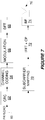
- Figure 7 illustrates additional details concerning transmit processing for the PACH according to some examples.
- a cyclic redundancy check CRC
- CRC cyclic redundancy check
- padding may be used to match the payload size including the CRC to one of multiple different payload sizes predefined as possible for the PACH (e.g., 200, 300, or 400 bits).
- the payload, CRC, and any possible padding is then channel coded (Block 64).
- the encoded data is then modulated (Block 66) so as to map the encoded data to modulation symbols (e.g., Quadrature Phase Shift Keying (QPSK) symbols).
- modulation symbols e.g., Quadrature Phase Shift Keying (QPSK) symbols.
- the resulting modulation symbols are Discrete Fourier Transform (DFT) precoded (Block 68), e.g., to achieve a low peak to average power ratio (PAPR) waveform.
- DFT Discrete Fourier Transform
- the precoded signal is next mapped to a predefined group of subcarriers (Block 70), and then passed through Block 72, which performs inverse fast fourier transform (IFFT) processing and adds a cyclic prefix (CP).
- IFFT inverse fast fourier transform
- CP cyclic prefix
- the resulting signal is beamformed (BF) at Block 74 before being transmitted (e.g., broadcasted) via one or more antennas 76.
- Figures 6A-6B illustrated the examples using one example deployment scenario, other deployment scenarios for system information are also possible.
- Figures 8A-8B illustrates a couple of other examples.
- common access information e.g., in the form of the C-AIT
- an overlaid node e.g., via LTE
- the common access information is delivered by each node, including an overlaid node as well as multiple nodes that serve different parts of the overlaid node's coverage area.
- all nodes may individually transmit an SS signal, SSB, and C-AIT, whereby each C-AIT may contain only a single entry related to the SS signal transmitted by the same node or each C-CAIT may contain multiple entries related to the SS signals transmitted by multiple nodes.
- each C-AIT may contain only a single entry related to the SS signal transmitted by the same node or each C-CAIT may contain multiple entries related to the SS signals transmitted by multiple nodes.
- C-AITs transmitted by different nodes could be time-shifted relative to one another.
- radio nodes with significantly different transmission power may need to have different system information.
- These different types of radio nodes in some examples have different system signatures.
- radio nodes may be partitioned into different power classes, each power class having its own system signature. Radio nodes having the same power class may have the same signature, unless different system signatures are needed for other reasons, e.g., backhaul capabilities, processing capabilities, or the like.
- the different types may also be classified based on activity level, e.g., radio nodes being in an active mode or sleep mode.
- system information associated with multiple system signatures may be broadcast by one or more of the radio nodes, e.g., in the form of a C-AIT, according to any of the deployment options herein.
- the system information may for instance be broadcast by only a few high-power radio nodes.
- a system signature may be compared to a traditional cell-specific reference signal (CRS) but with notable differences. Similar to a CRS, a system signature may be associated with system information, and controls the initial device transmissions. However, some radio nodes, even adjacent, may have the same system signature, e.g., as long as they have similar transmission power or activity. In fact, all radio nodes of the same type may have the same system signature. This contrasts with traditional systems in which a physical cell identity (PCI) conflict would occur in case two neighboring radio nodes would have the same PCI and hence transmit the same CRS. Indeed, transmission of the same system signature by adjacent radio nodes may add in a constructive manner rather than in an interfering manner. Another difference is that the actual system information may not be transmitted from the same radio node that transmits the system signature.
- PCI physical cell identity
- comparing with CRS it is enabled to either transmit the system signature with less power, which reduces network energy consumption, or larger cells in the macro layer deployment may be used. Larger cells in the macro layer also increase the support for radio network node sleep mode in the underlying network layers. For each active node there may be a larger number of in-active nodes if the macro layer is sparse. If two adjacent nodes are transmitting the same CRS in current systems then per definition they will form a joint cell. Since for a joint cell they must also transmit exactly the same synchronization signals and system broadcast signals. Also all CRS-based control and data channels must be transmitted in identical manner from both nodes.
- the device may be assigned a serving node/cell after the initial access has been performed. In the access procedure the device will receive information that enable it to access a node/cell (e.g., random access may not be node or cell specific). In fact, the node/cell might not have been there prior to the initial access of the device, e.g., it was in a non-active or dormant state.
- a device uses the initial access information in the C-AIT corresponding to a certain SS signal to request initial access to the system, and then thereafter uses other system information received after that initial access.
- the device may for instance receive some system information (e.g., multi-RAT lists) referred to as common system information after initial system access, and then receive other system information (e.g., transmission mode support or CRS configuration) referred to as non-specific system information after initial node access.
- some system information e.g., multi-RAT lists
- other system information e.g., transmission mode support or CRS configuration
- all or some of this other system information may already be known (e.g., preconfigured) at the device.
- a device stores an access information table (AIT) in its memory.
- the AIT may be updated based on a C-AIT received over common control plane signaling before initial system access and/or a dedicated AIT received over dedicated control plane signaling after initial system access.
- the AIT may therefore contain the same information as the C-AIT, the same information as the D-AIT, or some combination of the C-AIT and D-AIT.
- the D-AIT may contain some parameters (i.e., not entries) that are not included in the C-AIT, e.g., because they are not essential for initial system access. Such parameters may complement each entry in the table or be added to a common part separate from the entries. These parameters would thus also be included in the AIT, provided that the system 10 has transmitted the D-AIT to the device.
- the D-AIT may use the same SS signal to point to different configurations for different devices. For example, in the case of system congestion, this would allow the system 10 to have different access persistency values for different devices.
- system information in some examples is effectively decoupled from the traditional cell.
- This decoupling may be done in order to efficiently support increasingly important use cases and deployments such as higher order sectorization, Cloud radio access network (RAN), coordinated multipoint (CoMP), high frequency band operation, extreme area coverage, etc.
- RAN Cloud radio access network
- CoMP coordinated multipoint
- high frequency band operation extreme area coverage, etc.
- a new logical network entity may be effectively defined above the traditional cell or node.
- This new logical network entity may be referred to as a logical "anchor cell", “anchor area”, or “anchor node” (although other names may be a "super-cell", “hyper-cell”, etc.).
- the term anchor cell will be used hereinafter, with examples extending equally to anchor area, anchor node, etc.
- An anchor cell contains one or more cells, sectors, access node coverage areas, and/or beams. Some examples are shown in Figure 9 . In the examples in Figure 9 , one part of system information (e.g. SSB) may be sent from the different sectors (beams, etc.) and another part of the system information (e.g.
- C-AIT may be jointly transmitted over several sectors (beams, etc.).
- system information is transmitted from both individual cells (or sectors, beams, node coverage areas, etc.) as well as from logical anchor cells.
- some system information may be transmitted using a single node transmission format (e.g., cell broadcast) whereas other system information may be transmitted using a multi-node transmission format (e.g., OFDM SFN).
- the "SS+SSB" signals may be transmitted from a different set of nodes than the PACH.
- the number of combinations is likely to be large. Attempting to blindly decode the SS, SSB, and PACH in the face of all these combinations would cause additional access delay and consume device battery. Worse, even if the device were to succeed in blindly decoding the PACH, the device may have decoded a PACH that was not the correct one, but which is intended for another area, e.g. a neighboring anchor cell.
- the SS signals are only locally unique and different PACH transmissions may contain different information relating to different SSs.
- the PACH transmission (i.e. the C-AIT) may contain information that is associated with SSs that are used in the device's current anchor cell (including the (strongest) SS the device can currently receive), but which information is not valid in the device's current anchor cell (but e.g. in a neighboring anchor cell).
- the device can receive more than one PACH, then it may not know which one that is the intended one.
- the PACH is transmitted on a different frequency band (e.g. a lower frequency) with different distance dependent path loss it may be (in practice) impossible to exactly match the coverage area of the PACH with the union of the coverage areas of the constituent SS and SSB transmissions.
- the device will often receive more than one PACH in such a scenario.
- a C-AIT communicated inside a PACH transmission may contain information about (reused or different) SS signals that are not part of the same anchor cell. If the device cannot know from which PACH it has received the access information, then it would be unpredictable how the device would behave when it performs a system access. Depending on if the device has received the access information from another anchor cell or from this anchor cell, the access procedure could differ.
- the SSB may contain e.g. "PACH-DMRS-information" and/or "PACH-scrambling-code-information" and possibly a separate synchronization signal associated with the PACH (e.g. PACH-SS).
- the PACH may include the C-AIT.
- the PACH may also include an anchor cell global identity (ACGI) and/or a tracking RAN access code or tracking area code at the anchor cell level.
- ACGI anchor cell global identity
- various examples herein transmit explicit signaling that is associated with a first part 16 of system information and that identifies a second part 20 of system information as complementing that first part 16.
- the explicit signaling distinguishes the second part 20 from any other second part of system information in the system 10, e.g., so as to reduce ambiguity regarding which second part corresponds to the first part 16.
- This identification of the second part 20 may be accomplished through explicit signaling of a sequence used for demodulating or descrambling the second part 20.
- the identification may be accomplished through explicit signaling of a second part identifier or a second channel identifier (e.g., a PACH identifier).
- any examples described in terms of SSB and C-AIT/PACH may be generalized or extended to apply to any first part of system information and second part of system information. This may be further generalized to an arbitrary number (N) of system information parts.
- each system information part includes or is associated with information of the above described type(s) (e.g., format and demodulation-assisting information such as DMRS, scrambling sequence, associated synchronization signal sequence/index) related to the next system information part (i.e. a "sequential chain" of system information parts).
- the first system information part includes or is associated with format/demodulation-assisting information related to each of the other system information parts.
- any of the system information parts in a sequential chain of system information parts could include or be associated with format and demodulation-assisting information related to more than one other system information part (i.e. essentially turning the sequential chain into a "tree" of system information parts).
- first and second system information parts have been used herein, the terms first and second do not necessarily imply an ordering of the system information parts, e.g., whether in time, frequency, or otherwise.
- the wireless communication system 10 in some embodiments is an LTE system.
- the first part of system information may comprise a master information block (MIB) and the second part of system information may comprise a system information block (SIB).
- MIB master information block
- SIB system information block
- a radio node 12 herein is any type of node (e.g., a base station) capable of communicating with another node over radio signals.
- a wireless communication device 14 is any type device capable of communicating with a radio node 12 over radio signals.
- a wireless communication device 14 may therefore refer to a user equipment (UE), a mobile station, a laptop, a smartphone, a machine-to-machine (M2M) device, a machine-type communications (MTC) device, a narrowband Internet of Things (loT) device, etc. That said, although the wireless communication device 14 may be referred to as a UE, it should be noted that the wireless communication device 14 does not necessarily have a "user" in the sense of an individual person owning and/or operating the device.
- M2M machine-to-machine
- MTC machine-type communications
- LoT narrowband Internet of Things
- a wireless communication device 14 may also be referred to as a radio device, a radio communication device, a wireless terminal, or simply a terminal - unless the context indicates otherwise, the use of any of these terms is intended to include device-to-device UEs or devices, machine-type devices or devices capable of machine-to-machine communication, sensors equipped with a wireless device, wireless-enabled table computers, mobile terminals, smart phones, laptop-embedded equipped (LEE), laptop-mounted equipment (LME), USB dongles, wireless customer-premises equipment (CPE), etc.
- M2M machine-to-machine
- MTC machine-type communication
- wireless sensor and sensor may also be used. It should be understood that these devices may be UEs, but may be generally configured to transmit and/or receive data without direct human interaction.
- a wireless communication device as described herein may be, or may be comprised in, a machine or device that performs monitoring or measurements, and transmits the results of such monitoring measurements to another device or a network.
- machines are power meters, industrial machinery, or home or personal appliances, e.g. refrigerators, televisions, personal wearables such as watches etc.
- a wireless communication device as described herein may be comprised in a vehicle and may perform monitoring and/or reporting of the vehicle's operational status or other functions associated with the vehicle.
- a radio node 12 herein generally performs the method 100 shown in Figure 10 .
- the method 100 comprises generating explicit signaling that is associated with a first part 16 of system information and that indicates a sequence 24 with which a second part 20 of system information is to be demodulated or descrambled (Block 110).
- the method 100 also comprises transmitting the explicit signaling over a signaling channel 25 (Block 120).
- the method 100 in some examples comprises transmitting the first part 16 of system information over the first channel 18 (Block 130), whereas in other examples a different radio node transmits this first part 16.
- the method 100 in some examples comprises transmitting the second part 20 of system information over the second channel 22 (Block 140), whereas in other examples a different radio node transmits this second part 20.
- a wireless communication device 14 herein correspondingly performs the method 200 shown in Figure 11 for receiving system information for a wireless communication system in parts.
- the method 200 comprises receiving, over a first channel 18, a first part 16 of system information (Block 210).
- the method 200 also comprises receiving, over a signaling channel, explicit signaling that is associated with the first part 15 and that indicates a sequence 24 with which the wireless communication device 14 is to demodulate or descramble a second part 20 of system information (Block 220).
- the method 200 also comprises receiving the second part 20 of system information over a second channel 22, by demodulating or descrambling the second part 20 using the indicated sequence 24 (Block 230).
- the method 200 also comprises accessing the wireless communication system 10 using both the first and second parts 16, 20 of system information (Block 240).
- the radio node 12 as described above may perform any of the processing herein by implementing any functional means or units.
- the radio node 12 comprises respective circuits or circuitry configured to perform the steps shown in Figure 10 .
- the circuits or circuitry in this regard may comprise circuits dedicated to performing certain functional processing and/or one or more microprocessors in conjunction with memory.
- memory which may comprise one or several types of memory such as read-only memory (ROM), random-access memory, cache memory, flash memory devices, optical storage devices, etc.
- the memory stores program code that, when executed by the one or more processors, carries out the techniques described herein.
- FIG. 12 illustrates a radio node 12 implemented in the form of a radio node 12A in accordance with one or more examples.
- the radio node 12A includes processing circuitry 300 and communication circuitry 310.
- the communication circuitry 310 is configured to transmit and/or receive information to and/or from one or more other nodes, e.g., via any communication technology.
- the processing circuitry 300 is configured to perform processing described above, e.g., in Figure 10 , such as by executing instructions stored in memory 320.
- the processing circuitry 300 in this regard may implement certain functional means, units, or modules.
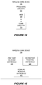
- FIG 13 illustrates a radio node 12 implemented in the form of a radio node 12B in accordance with one or more other examples.
- the radio node 12B implements various functional means, units, or modules, e.g., via the processing circuitry 300 in Figure 12 and/or via software code.
- These functional means, units, or modules, e.g., for implementing the method in Figure 10 include for instance a generating unit or module 400 for generating explicit signaling that is associated with a first part 16 of system information and that indicates a sequence 24 with which a second part 20 of system information is to be demodulated or descrambled.
- a transmitting unit or module 410 for transmitting the explicit signaling over a signaling channel 25.
- a wireless communication device 14 as described above may perform any of the processing herein by implementing any functional means or units.
- the wireless communication device 14 comprises respective circuits or circuitry configured to perform the steps shown in Figure 11 .
- the circuits or circuitry in this regard may comprise circuits dedicated to performing certain functional processing and/or one or more microprocessors in conjunction with memory.
- memory which may comprise one or several types of memory such as read-only memory (ROM), random-access memory, cache memory, flash memory devices, optical storage devices, etc.
- the memory stores program code that, when executed by the one or more processors, carries out the techniques described herein.
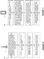
- Figure 14 illustrates a wireless communication device 14 implemented in the form of a wireless communication device 14A
- the wireless communication device 14A includes processing circuitry 500 and communication circuitry 510.
- the communication circuitry 510 is configured to transmit and/or receive information to and/or from one or more other nodes, e.g., via any communication technology.
- the processing circuitry 500 is configured to perform processing described above, e.g., in Figure 11 , such as by executing instructions stored in memory 520.
- the processing circuitry 500 in this regard may implement certain functional means, units, or modules.
- Figure 15 illustrates a wireless communication device 14 implemented in the form of a wireless communication device 14B.
- the wireless communication device 14B implements various functional means, units, or modules, e.g., via the processing circuitry 500 in Figure 14 and/or via software code.
- These functional means, units, or modules, e.g., for implementing the method in Figure 11 include for instance a first part receiving unit or module 600 for receiving, over a first channel 18, a first part 16 of system information.
- a signaling unit or module 610 for receiving, over a signaling channel 25, explicit signaling that is associated with the first part 16 and that indicates a sequence 24 with which the wireless communication device 14 is to demodulate or descramble a second part 20 of system information.
- a second part receiving unit or module 620 for receiving the second part 20 of system information over a second channel 22, by demodulating or descrambling the second part 20 using the indicated sequence 24.
Description
- The present application relates generally to system information for a wireless communication system, and particularly to transmission and reception of that system information in parts.
- A wireless communication system transmits system information to wireless communication devices within the system's coverage area. This system information includes for example access information indicating how wireless communication devices may access the system, e.g., initially via random access. The access information may specify for instance parameters that indicate control the timing, frequency, transmission formats, and/or power used by a device for initial access.
- Traditionally, a wireless communication system broadcasts cell-specific system information from each of the system's cells. This allows different system information to be broadcast from different cells, e.g., to be able to distinguish between accesses made in different cells, or to adjust initial transmission power levels on a cell-specific basis.
- Especially as wireless communication systems densify, though, broadcasting system information using this traditional approach proves inefficient and costly in terms of radio resources and energy. Modern approaches therefore seek to minimize the amount of system information that is broadcast, and to limit how often that information is broadcast. Some approaches for example broadcast a table of limited system information relatively infrequently, and broadcast an index into that table relatively frequently.
US 2014/295836 A1 discloses a system for indicating a set of system information to a UE by broadcasting only a system signature (broadcasted first part), wherein the UE stores a mapping between the signature and broadcasted system information (broadcasted second part), thereby requiring less data exchange for setting up a communication.US 2015/085717 A1 discloses to provide a minimum amount of system information by means of MIB and the rest of system information by means of one or more SIBs. Further, discloses that a UE receives from a base station a demodulation reference signal, DMRS, to demodulate PDSCH or PDCCH. In these and other approaches challenges still exist in efficiently distributing system information to wireless communication devices. - Embodiments disclosed herein relates to a wireless communication device and a radio node configured for use in a wireless communication system. Although different aspects of embodiments are given below, the scope of protection of the application is defined by the claims.
- Embodiments herein also include corresponding methods, computer programs, and computer program products.
-
-
Figure 1 is a block diagram of a wireless communication system. -
Figure 2 is a block diagram of a system in which multiple second parts of system information are receivable. -
Figure 3 is a block diagram of a system in which a second part of system information comprises a table. -
Figure 4 is a block diagram of an access information table. -
Figure 5 is a logic flow diagram of processing performed by a wireless communication device for receiving system information in parts. -
Figure 6A is a block diagram of system information transmission. -
Figure 6B is a timing diagram of system information transmission. -
Figure 7 is a block diagram of a transmit chain for system information transmission. -
Figures 8A-8B are block diagrams of system information transmission. -
Figure 9 is a block diagram of different deployment options for a logical anchor cell. -
Figure 10 is a logic flow diagram of a method performed by a radio node configured for use in a wireless communication system in which system information is transmitted in parts. -
Figure 11 is a logic flow diagram of a method performed by a wireless communication device for receiving system information in parts. -
Figure 12 is a block diagram of a radio node. -
Figure 13 is a block diagram of a radio node. -
Figure 14 is a block diagram of a wireless communication device. -
Figure 15 is a block diagram of a wireless communication device. -
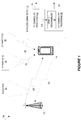
Figure 1 illustrates awireless communication system 10. Thesystem 10 includes one or more radio nodes (e.g., base station(s)) such asradio node 12. Thesystem 10 also includes one or more wireless communication devices (e.g., user equipment) such aswireless communication device 14. Thesystem 10 is configured to transmit system information to thewireless communication device 14. System information as used herein may refer to any information transmitted to a wireless communication device to facilitate the wireless communication device operating in or accessing thesystem 10. System information may include for example information describing configuration(s) for random access to thesystem 10, tracking and paging related information, neighbor cell information, a list of public land mobile network (PLMN) identifiers, access barring information, or the like. - No matter the particular content of the system information, the system information for the
system 10 is transmitted in parts. As shown in this regard, thesystem 10 via one or more radio nodes transmits afirst part 16 of the system information over afirst channel 18. Thesystem 10 also transmits asecond part 20 of the system information over asecond channel 22. Thefirst part 16 may indicate one portion of the system information, whereas thesecond part 18 may indicate another portion of the system information. - In this context, a
radio node 12 herein transmits explicit signaling that is associated with the first part (16) and that indicates asequence 24 with which thewireless communication device 14 is to demodulate or descramble thesecond part 20 ofsystem information 20. In some sense, then, the explicit signaling facilitates thewireless communication device 14 receiving system information; namely, the system information in thesecond part 20. The signaling is explicit in the sense that it comprises one or more bits, symbols, or other information elements that encode or represent the sequence 24 (e.g., as a sequence index). Thesequence 24 may be a demodulation reference signal (DMRS) sequence, a scrambling code sequence, or a synchronization signal sequence. Regardless, theradio node 12 transmits this explicit signaling over asignaling channel 25. Having received this explicit signaling, thewireless communication device 14 receives thesecond part 20 of system information over thesecond channel 22, by demodulating or descrambling thesecond part 20 uses the indicatedsequence 24. - The explicit signaling may be associated with the
first part 16 in any number of ways. In some examples, the explicit signaling is included or otherwise embedded in thefirst part 16 along with system information, so as to effectively accompany the system information indicated by thefirst part 16. In this case, therefore, theradio node 12 transmits both thefirst part 16 of system information and the explicit signaling included in thatfirst part 16 over the same channel, i.e., thefirst channel 18 and thesignaling channel 25 are one and the same. - In other examples, the explicit signaling is associated with the
first part 16 even where the explicit signaling is not actually included in or embedded in the first part 15. For example, in one example, the explicit signaling includes an identifier of thefirst part 16. Alternatively or additionally, the explicit signaling may be receivable using the same reference signal as that with which thefirst part 16 is receivable. For example, the same sequence index (e.g., system signature index, SSI, as described more fully below) may be used to derive a demodulation reference signal which is used to demodulate both the first part (16) and the explicit signaling, though received separately from one another. That is, even if the explicit signaling is excluded from thefirst part 16 of system information, the explicit signaling may be associated with thatfirst part 16 in the sense that the explicit signaling is configured to be demodulated based on the same sequence with which thefirst part 16 of system information is configured to be demodulated. -
Figure 1 shows example device processing where the explicit signaling is included in thefirst part 16. In this case, thewireless communication device 14 may perform receiver processing 26 on thefirst channel 18 in order to recover thefirst part 16 of system information. Thewireless communication device 14 may then extract thesequence 24 embedded in thefirst part 16 of system information and use thatsequence 24 to perform receiver processing 28 on thesecond channel 22. In particular, thedevice 14 may use the extractedsequence 24 to perform demodulation or descrambling 30 of thesecond part 20 ofsystem information 20. Thewireless communication device 14 then accesses 12 thewireless communication system 10 using both the first andsecond parts - The
sequence 24 distinguishes thesecond part 20 of system information from one or more other second parts of system information that are receivable using one or more other respective sequences for demodulating or descrambling. In one or more examples, these different sequences are orthogonal such that demodulating or descrambling a second part of system information using a sequence other than that with which the second part was configured prevents recovery of that second part, e.g., the second part just appears as noise.Figure 2 shows one example. - As shown, different
second parts 20A-C of system information are transmitted in thesystem 10. Thesesecond parts 20A-20C may comprise system information of the same type, may be received overchannels 22A-22C of the same type, and may complement respective first parts of system information. But thesecond parts 20A-20C may indicate different values for the system information of that type. For example, eachsecond part 20A-20C may indicate that thewireless communication device 14 is to access thesystem 10 using different random access preambles or different random access powers. In view of this, thesecond parts 20A-20C are configured to be receivable by thewireless communication device 14 using different sequences for demodulating or descrambling. As shown, for instance,second part 20A is receivable using sequence A, whereassecond parts - In this way, the
second parts 20A-20C are effectively paired with and only recoverable in conjunction with the respective first parts that are associated with explicit signaling that indicates the corresponding sequences A-C. This means that, upon receipt of a given first part of system information, a single targeted one of multiple different possiblesecond parts 20A-20C is unambiguously receivable using the sequence signaled in association with that first part. This advantageously prevents or minimizes ambiguity regarding whichsecond part 20A-20C complements a received first part of system information. - Similarly, consider examples where multiple different possible
second parts 20A-20C of system information include respective tables 34A-34C of the same type, as shown inFigure 3 . The tables 34A-34C are each accessible using anindex 36 obtained by thedevice 14, e.g., based on reception of asignal 38 such as a synchronization signal. Theindex 36 in this regard may be a valid index into each of the tables 34A-34C, but may map to entries in the different tables 34A-34C that contain different system information (e.g., different random access preambles). Because of this, ambiguity would otherwise exist regarding which of the tables 34A-34C is targeted by theindex 36, i.e., which of the tables 34A-34C theindex 36 was actually intended to index into. This ambiguity is resolved by a sequence 24A indicated by explicit signaling that as shown here is included in afirst part 16A of system information associated with the obtainedindex 36. In this example, the associated sequence 24A distinguishes thesecond part 20A of system information as including the table 34A targeted by theindex 36, e.g., as opposed to othersecond parts index 36. - In some examples, the tables 34A-34C are each of the same type in the sense that they are each an access information table.
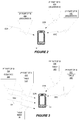
Figure 4 shows an example of table 34A in such examples. As shown, the table 34A containsmultiple configurations wireless communication system 10. Different configurations may configure awireless communication device 14 to access thesystem 10 in different ways, e.g., using different values for a certain access parameter. Themultiple configurations different indices - Tables 34B and 34C may be formed in a similar way, but with different configurations for accessing the
system 10, or at least different mappings between indices and configurations. Thus, particularly when the table 34A has at least as many configuration entries as that of the other tables 34B-34C transmitted in thesystem 10, any givenindex sequence 24 indicated by explicit signaling that is included in or otherwise associated with thefirst part 16 of system information. -
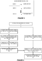
Figure 5 illustrates processing performed by awireless communication device 14 in this regard, in examples where thedevice 14 obtains the index based on a so-called system signature (SS) signal. Indeed, as shown, thedevice 14 receives a SS signal (Block 40). The SS signal may be a synchronization signal in some examples. Regardless, the SS signal indicates one of multiple different possible system signatures for thesystem 10. When thedevice 14 needs to access thesystem 10, it may search for an SS signal. In case thedevice 14 detects multiple SS signals, thedevice 14 may perform this processing on individual ones of the detected SS signals, as needed, in order of signal strength, quality, or other signal characteristic (e.g., thedevice 14 may initially select the strongest one). - Based on a received SS signal, the
device 14 determines a table index (Block 42). The SS signal may for example encode or map to the table index. In this example, the table index is an index into an access information table. But multiple access information tables are transmitted in thesystem 10. To identify which of the access information tables the table index is intended to index into, thedevice 14 receives afirst part 16 of system information also based on the SS signal (Block 44). Thedevice 14 may for example derive or otherwise determine a sequence (e.g., a DMRS sequence, descrambling sequence, or synchronization signal sequence) from the SS signal, e.g., using a one-to-one mapping between SS signals and sequences, as for example preconfigured through standardization, the device's universal subscriber identity module (USIM), etc. Thedevice 14 may then receive thefirst part 16 using that sequence. In some examples, this sequence used for receiving thefirst part 16 is different than the sequence used for receiving thesecond part 20 of system information. In any event, the table index and thefirst part 16 are (uniquely) associated with one another through having been determined based on the same signal, i.e., the same SS signal. - Next, similar to that described above, the
device 14 determines asequence 24 from explicit signaling included in or otherwise associated with thefirst part 16 of system information (Block 46). Thedevice 14 demodulates or descrambles thesecond part 20 of system information using this determined sequence 24 (block 48), and retrieves or recovers an access information table from the second part 20 (Block 50). With thesequence 24 having distinguished thissecond part 20 from other possible second parts in the system, thesequence 24 effectively identifies the access information table included in thissecond part 20 as being the table into which the table index is intended to index into. That is, thesequence 24 distinguishes the particular access information table included in thesecond part 20 as being the target of the index associated with the SS signal (and thereby thefirst part 16 of system information, given the association between thefirst part 16 and the system signature signal). - Accordingly, the
device 14 identifies the configuration in the retrieved access information table that is indexed by the table index (Block 52). Thedevice 14 may do so by selecting from the different configurations in the table the configuration to which the table index maps. Thedevice 14 then accesses thesystem 10 using the identified configuration (Block 54). - In some examples, the
configurations system 10, e.g., via random access. In this and other examples,different configurations device 14 to initially access thesystem 10 by performing random access with different random access configurations (e.g., with different random access preambles, timing, transmit power, and/or other random access parameters). Alternatively or additionally,different configurations device 14 to initially access thesystem 10 by using different public land mobile network (PLMN) identifiers. -
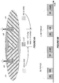
Figure 6A illustrates one example in a context where a second part of system information constitutes common access information that is commonly transmitted inmultiple areas 56A-B, whereas different first parts of system information are respectively transmitted in thosemultiple areas 56A-B. Radio nodes radio nodes radio nodes 12A-12B may be lower power radio nodes that broadcasts different first parts of system information over a relatively smaller coverage area, whereas a higher power radio node (not shown) broadcasts the second part of system information over a relatively larger, overlapping coverage area. The different first parts of system information in this regard may indicate different system information of the same type, such that this different system information is respectively transmitted indifferent areas 56A-B. - With the second part of system information transmitted in this way, the access information table included in that second part is appropriately referred to as a common access information table (C-AIT). The C-AIT and any other common access information included in the second part may be transmitted (e.g., broadcasted) over a common access information channel (here referred to as a physical anchor channel, PACH). The second part may therefore be referred to for convenience as the PACH system information.
- By contrast, a first part of system information transmitted in an
individual area area 56A and SSB2 transmitted inarea 56B. As shown, therefore, a first SS signal (SS1) and a first SSB (SSB1) is transmitted inarea 56A, whereas a second SS signal (SS2) and a second SSB (SSB2) is transmitted inarea 56B. The first SS signal (SS1) is associated with a first C-AIT index (Index 1) which is mapped to a first access information configuration (Config 1) in the C-AIT. The second SS signal (SS2) is associated with a second C-AIT index (Index 2) which is mapped to a second access information configuration (Config 2) in the same C-AIT. Both the first SS block (SSB1) and the second SS block (SSB2) therefore contain or are otherwise associated with explicit signaling that indicates the same sequence for demodulating or descrambling the PACH system information. The sequence indicated by this explicit signaling may distinguish the PACH as conveying the C-AIT targeted by the first and second C-AIT indices, as opposed to any other C-AIT conveyed by another PACH whose transmission may leak intoareas 56A and/or 56B. -
Figure 6B indicates the transmission timing of the SS, SSB, and C-AIT according to some examples where the first part of system information (in the form of an SS signal) is transmitted more frequently than the second part of system information (in the form of the C-AIT). As shown, for example, an SS signal has a transmission period that is shorter than the transmission period of the C-AIT. - In general, though, the SS transmission period and the C-AIT transmission period may be a tradeoff between system energy performance, device energy performance, and access latency in cases where the SS needs to be read before access. In some deployments, therefore, the C-AIT period may be the same as the SS period (e.g., in small indoor networks). In other examples, the C-AIT period may be very large (e.g., 10 seconds), in order to support extremely power limited scenarios (e.g., off-grid solar powered base stations). For typical deployment scenarios, however, the SS transmission period may be between 5-100ms and the C-AIT transmission period may be between 5-2000ms. The SS period may depend on a detected level of communication activity to or from the radio node transmitting that SS. With the SS being smaller in size than the C-AIT (e.g., since the SS conveys an index into the C-AIT rather than the C-AIT itself), a shorter SS period than the C-AIT period facilitates system information changes with reduced signaling load. Indeed, system information changes may be accomplished by sending a smaller-sized SS without an accompanying larger-sized C-AIT.
- An SSB may be transmitted in order to convey system information that cannot be conveyed via an SS signal (e.g., via a synchronization signal sequence), or need not be conveyed with the same transmit period as an SS signal or C-AIT. An SSB may be transmitted for instance after every Nth SS transmission, where for instance N=1, 2,..., 20.
Figure 6B for instance shows an example where N=2. The transmission period of the SSB, though, depends on the timing needs for the system information that it conveys. - An SSB in this regard conveys system information and includes or is otherwise associated with explicit signaling that indicates a sequence for demodulating or descrambling the PACH system information. The explicit signaling (e.g., including in the SSB) may indicate one or more sequences towards this end. The signaling for example indicate one or both of a DMRS sequence and a scrambling code sequence. A
device 14 may therefore demodulate the PACH using the indicated DMRS sequence and/or descramble the PACH using the indicated scrambling code sequence. - The explicit signaling associated with an SSB alternatively or additionally indicates a synchronization signal sequence that may be used as a timing reference for demodulating the PACH, i.e., a PACH-SS where SS as used in this way is defined to denote a synchronization signal. The PACH-SS may be indicated or actually used by a
device 14 for fine-tuned time synchronization if for example the PACH is transmitted by a radio node different than the radio node(s) transmitting the corresponding SS signal and the SSB, without tight time synchronization between those nodes (e.g., within a cyclic prefix). The PACH-SS may be indicated or used by adevice 14 also if the PACH is transmitted on a different frequency band than the band on which the corresponding SS signal and SSB are transmitted. Otherwise, if the PACH is transmitted on the same frequency band as the SS signal and the SSB, if the PACH is transmitted the same radio node as the SS signal and SSB, or if the PACH is transmitted by a different radio node that is tightly time synchronized with the radio node transmitting the SS signal and SSB, the PACH-SS may not be indicated by the SSB or even if it is not used by thedevice 14. In general, therefore, adevice 14 may at least partly derive the timing of the SSB and the PACH from the same or different synchronization signals. The transmit format of the SSB may be at least partly derived from an index associated with its corresponding synchronization signal, whereas the transmit format of the PACH may be at least partly derived from system information embedded or otherwise included in the SSB. - Accordingly, in the explicit signaling associated with the SSB generally indicates a transmission format describing how the C-AIT is transmitted (e.g., via a "PACH format information" field). The explicit signaling in this regard may include information describing radio resources on which the C-AIT transmission occurs (e.g., in the form of a "C-AIT pointer"). The information may for example indicate the time and/or frequency resources on which the C-AIT transmission occurs, e.g., by indicating a resource location and/or size of the channel over which the C-AIT is transmitted (i.e., the PACH). The information may indicate the PACH time and/or frequency resources in terms of a number of sub-subcarriers, a number of OFDM symbols for the PACH, a frequency band for the PACH, a radio access technology (RAT) used for the PACH, or the like.
- Alternatively or additionally, the explicit signaling associated with an SSB may include information indicating a modulation and coding scheme (MCS) used on the PACH. The information may indicate this in terms of a number of information bits, a number of channel bits, a modulation index, channeling coding information (e.g., redundancy version), or the like. In still other examples, the explicit signaling associated with an SSB may indicate an antenna configuration of the PACH. The signaling may indicate this in terms of a precoder used for the PACH, a number of antennas used to transmit on the PACH, a diversity encoding scheme, or the like. In yet other examples, the explicit signaling associated with an SSB may indicate an identifier for the PACH. Alternatively or additionally, the explicit signaling associated with an SSB may indicate a system frame number (SFN), a system information value tag or hash code, one or more PLMN IDs (e.g., as a compressed list), tracking area information, timing information for device waking up after long sleep periods, etc.
- The PACH in some examples conveys other common access information in addition to the C-AIT. Other common access information in this regard may include a global time, a PLMN ID list, common access barring information, tracking area information, or the like. In one or more examples, the PACH also conveys earthquake and tsunami warning system (ETWS) information and/or commercial mobile alert system (CMAS) information indicating how to access the ETWS and/or CMAS. The PACH may have a dynamic size in order to flexibly include all or some of this information on a dynamic basis.
-
Figure 7 illustrates additional details concerning transmit processing for the PACH according to some examples. As shown, a cyclic redundancy check (CRC) is added to thepayload 60 of the PACH (Block 62). In one or more examples that support flexible payload size, padding may be used to match the payload size including the CRC to one of multiple different payload sizes predefined as possible for the PACH (e.g., 200, 300, or 400 bits). The payload, CRC, and any possible padding is then channel coded (Block 64). The encoded data is then modulated (Block 66) so as to map the encoded data to modulation symbols (e.g., Quadrature Phase Shift Keying (QPSK) symbols). The resulting modulation symbols are Discrete Fourier Transform (DFT) precoded (Block 68), e.g., to achieve a low peak to average power ratio (PAPR) waveform. The precoded signal is next mapped to a predefined group of subcarriers (Block 70), and then passed throughBlock 72, which performs inverse fast fourier transform (IFFT) processing and adds a cyclic prefix (CP). In some examples, the resulting signal is beamformed (BF) atBlock 74 before being transmitted (e.g., broadcasted) via one ormore antennas 76. - Although
Figures 6A-6B illustrated the examples using one example deployment scenario, other deployment scenarios for system information are also possible.Figures 8A-8B illustrates a couple of other examples. InFigure 8A , for instance, common access information, e.g., in the form of the C-AIT, is delivered by an overlaid node (e.g., via LTE), rather than jointly via multiple nodes that serve different parts of the overlaid node's coverage area. InFigure 8B , by contrast, the common access information is delivered by each node, including an overlaid node as well as multiple nodes that serve different parts of the overlaid node's coverage area. That is, all nodes may individually transmit an SS signal, SSB, and C-AIT, whereby each C-AIT may contain only a single entry related to the SS signal transmitted by the same node or each C-CAIT may contain multiple entries related to the SS signals transmitted by multiple nodes. However, there could be heavy interference for C-AIT reception within a synchronized network on the same frequency. To avoid C-AIT interference, C-AITs transmitted by different nodes could be time-shifted relative to one another. - In some examples, different types of radio nodes with significantly different transmission power may need to have different system information. These different types of radio nodes in some examples have different system signatures. For instance, radio nodes may be partitioned into different power classes, each power class having its own system signature. Radio nodes having the same power class may have the same signature, unless different system signatures are needed for other reasons, e.g., backhaul capabilities, processing capabilities, or the like. The different types may also be classified based on activity level, e.g., radio nodes being in an active mode or sleep mode. Regardless, system information associated with multiple system signatures may be broadcast by one or more of the radio nodes, e.g., in the form of a C-AIT, according to any of the deployment options herein. The system information may for instance be broadcast by only a few high-power radio nodes.
- In these and other examples, a system signature may be compared to a traditional cell-specific reference signal (CRS) but with notable differences. Similar to a CRS, a system signature may be associated with system information, and controls the initial device transmissions. However, some radio nodes, even adjacent, may have the same system signature, e.g., as long as they have similar transmission power or activity. In fact, all radio nodes of the same type may have the same system signature. This contrasts with traditional systems in which a physical cell identity (PCI) conflict would occur in case two neighboring radio nodes would have the same PCI and hence transmit the same CRS. Indeed, transmission of the same system signature by adjacent radio nodes may add in a constructive manner rather than in an interfering manner. Another difference is that the actual system information may not be transmitted from the same radio node that transmits the system signature.
- Further in this regard, comparing with CRS, it is enabled to either transmit the system signature with less power, which reduces network energy consumption, or larger cells in the macro layer deployment may be used. Larger cells in the macro layer also increase the support for radio network node sleep mode in the underlying network layers. For each active node there may be a larger number of in-active nodes if the macro layer is sparse. If two adjacent nodes are transmitting the same CRS in current systems then per definition they will form a joint cell. Since for a joint cell they must also transmit exactly the same synchronization signals and system broadcast signals. Also all CRS-based control and data channels must be transmitted in identical manner from both nodes. If they fail to do any of this then a PCI-conflict appears and that is something that is not allowed to happen during normal operation. This is an error event that will cause dropped calls and handover failures and it must be resolved. With system signatures, this is allowed since the device does not assume that any single node transmits the system signature. The device may be assigned a serving node/cell after the initial access has been performed. In the access procedure the device will receive information that enable it to access a node/cell (e.g., random access may not be node or cell specific). In fact, the node/cell might not have been there prior to the initial access of the device, e.g., it was in a non-active or dormant state.
- Accordingly, in some examples, a device uses the initial access information in the C-AIT corresponding to a certain SS signal to request initial access to the system, and then thereafter uses other system information received after that initial access. The device may for instance receive some system information (e.g., multi-RAT lists) referred to as common system information after initial system access, and then receive other system information (e.g., transmission mode support or CRS configuration) referred to as non-specific system information after initial node access. In still other examples, though, all or some of this other system information may already be known (e.g., preconfigured) at the device.
- In some examples, for example, a device stores an access information table (AIT) in its memory. The AIT may be updated based on a C-AIT received over common control plane signaling before initial system access and/or a dedicated AIT received over dedicated control plane signaling after initial system access. The AIT may therefore contain the same information as the C-AIT, the same information as the D-AIT, or some combination of the C-AIT and D-AIT.
- Note that the D-AIT may contain some parameters (i.e., not entries) that are not included in the C-AIT, e.g., because they are not essential for initial system access. Such parameters may complement each entry in the table or be added to a common part separate from the entries. These parameters would thus also be included in the AIT, provided that the
system 10 has transmitted the D-AIT to the device. The D-AIT may use the same SS signal to point to different configurations for different devices. For example, in the case of system congestion, this would allow thesystem 10 to have different access persistency values for different devices. - In view of the above, system information in some examples is effectively decoupled from the traditional cell. This decoupling may be done in order to efficiently support increasingly important use cases and deployments such as higher order sectorization, Cloud radio access network (RAN), coordinated multipoint (CoMP), high frequency band operation, extreme area coverage, etc.
- As a consequence, a new logical network entity may be effectively defined above the traditional cell or node. This new logical network entity may be referred to as a logical "anchor cell", "anchor area", or "anchor node" (although other names may be a "super-cell", "hyper-cell", etc.). The term anchor cell will be used hereinafter, with examples extending equally to anchor area, anchor node, etc. An anchor cell contains one or more cells, sectors, access node coverage areas, and/or beams. Some examples are shown in
Figure 9 . In the examples inFigure 9 , one part of system information (e.g. SSB) may be sent from the different sectors (beams, etc.) and another part of the system information (e.g. C-AIT) may be jointly transmitted over several sectors (beams, etc.). In the context of asystem 10 that has both regular cells and anchor cells, therefore, system information is transmitted from both individual cells (or sectors, beams, node coverage areas, etc.) as well as from logical anchor cells. For example, some system information may be transmitted using a single node transmission format (e.g., cell broadcast) whereas other system information may be transmitted using a multi-node transmission format (e.g., OFDM SFN). - In this context, the "SS+SSB" signals may be transmitted from a different set of nodes than the PACH. The number of combinations is likely to be large. Attempting to blindly decode the SS, SSB, and PACH in the face of all these combinations would cause additional access delay and consume device battery. Worse, even if the device were to succeed in blindly decoding the PACH, the device may have decoded a PACH that was not the correct one, but which is intended for another area, e.g. a neighboring anchor cell. Indeed, in some examples, the SS signals are only locally unique and different PACH transmissions may contain different information relating to different SSs. Note that this also means that SSs may be reused and be associated with different access information in different areas (e.g. in different anchor cells). Hence, the PACH transmission (i.e. the C-AIT) may contain information that is associated with SSs that are used in the device's current anchor cell (including the (strongest) SS the device can currently receive), but which information is not valid in the device's current anchor cell (but e.g. in a neighboring anchor cell). In case the device can receive more than one PACH, then it may not know which one that is the intended one.
- In case the PACH is transmitted on a different frequency band (e.g. a lower frequency) with different distance dependent path loss it may be (in practice) impossible to exactly match the coverage area of the PACH with the union of the coverage areas of the constituent SS and SSB transmissions. The device will often receive more than one PACH in such a scenario.
- As mentioned above, a C-AIT communicated inside a PACH transmission may contain information about (reused or different) SS signals that are not part of the same anchor cell. If the device cannot know from which PACH it has received the access information, then it would be unpredictable how the device would behave when it performs a system access. Depending on if the device has received the access information from another anchor cell or from this anchor cell, the access procedure could differ.
- One or more examples address these scenarios by introducing a field in or otherwise associated with the first system information part that is used to demodulate or descramble the second system information part. In the context of the above example, this would for example mean that the SSB may contain e.g. "PACH-DMRS-information" and/or "PACH-scrambling-code-information" and possibly a separate synchronization signal associated with the PACH (e.g. PACH-SS). The PACH may include the C-AIT. The PACH may also include an anchor cell global identity (ACGI) and/or a tracking RAN access code or tracking area code at the anchor cell level.
- Generally, various examples herein transmit explicit signaling that is associated with a
first part 16 of system information and that identifies asecond part 20 of system information as complementing thatfirst part 16. In this way, the explicit signaling distinguishes thesecond part 20 from any other second part of system information in thesystem 10, e.g., so as to reduce ambiguity regarding which second part corresponds to thefirst part 16. This identification of thesecond part 20 may be accomplished through explicit signaling of a sequence used for demodulating or descrambling thesecond part 20. Alternatively or additionally, the identification may be accomplished through explicit signaling of a second part identifier or a second channel identifier (e.g., a PACH identifier). - Note that the borders between concepts like cells, sectors, access node coverage areas and beams may be somewhat blurred in forthcoming wireless communication system (e.g., 5G systems). This is because its relevance can be questioned, as beamforming becomes prevalent and functions and mechanisms that traditionally have been tied to a cell get distributed across multiple access nodes. Accordingly, although the term cell has been used to describe some examples (e.g. when describing the new logical network entity as consisting of a logical entity containing a set of cells), those examples extend equally no matter the particular nomenclature used to supersede the traditional "cell" term.
- Moreover, although some examples are described in the context of an envisioned future 5G access system with SS Block and C-AIT transmitted by the system, the examples equally apply in a generic system with multiple system information parts. In this regard, any examples described in terms of SSB and C-AIT/PACH may be generalized or extended to apply to any first part of system information and second part of system information. This may be further generalized to an arbitrary number (N) of system information parts. That is, the above described examples may be generalized to more than two system information parts, such that each system information part includes or is associated with information of the above described type(s) (e.g., format and demodulation-assisting information such as DMRS, scrambling sequence, associated synchronization signal sequence/index) related to the next system information part (i.e. a "sequential chain" of system information parts). Alternatively, the first system information part includes or is associated with format/demodulation-assisting information related to each of the other system information parts. In a generalization of these two principles, hybrids between the two principles are possible, wherein any of the system information parts in a sequential chain of system information parts could include or be associated with format and demodulation-assisting information related to more than one other system information part (i.e. essentially turning the sequential chain into a "tree" of system information parts). Accordingly, while first and second system information parts have been used herein, the terms first and second do not necessarily imply an ordering of the system information parts, e.g., whether in time, frequency, or otherwise.
- Furthermore, although some examples have been described in the context of future 5G systems, the examples are equally extendable to other types of systems. For example, the
wireless communication system 10 in some embodiments is an LTE system. In this case, the first part of system information may comprise a master information block (MIB) and the second part of system information may comprise a system information block (SIB). - A
radio node 12 herein is any type of node (e.g., a base station) capable of communicating with another node over radio signals. Awireless communication device 14 is any type device capable of communicating with aradio node 12 over radio signals. Awireless communication device 14 may therefore refer to a user equipment (UE), a mobile station, a laptop, a smartphone, a machine-to-machine (M2M) device, a machine-type communications (MTC) device, a narrowband Internet of Things (loT) device, etc. That said, although thewireless communication device 14 may be referred to as a UE, it should be noted that thewireless communication device 14 does not necessarily have a "user" in the sense of an individual person owning and/or operating the device. Awireless communication device 14 may also be referred to as a radio device, a radio communication device, a wireless terminal, or simply a terminal - unless the context indicates otherwise, the use of any of these terms is intended to include device-to-device UEs or devices, machine-type devices or devices capable of machine-to-machine communication, sensors equipped with a wireless device, wireless-enabled table computers, mobile terminals, smart phones, laptop-embedded equipped (LEE), laptop-mounted equipment (LME), USB dongles, wireless customer-premises equipment (CPE), etc. In the discussion herein, the terms machine-to-machine (M2M) device, machine-type communication (MTC) device, wireless sensor, and sensor may also be used. It should be understood that these devices may be UEs, but may be generally configured to transmit and/or receive data without direct human interaction. - In an IOT scenario, a wireless communication device as described herein may be, or may be comprised in, a machine or device that performs monitoring or measurements, and transmits the results of such monitoring measurements to another device or a network. Particular examples of such machines are power meters, industrial machinery, or home or personal appliances, e.g. refrigerators, televisions, personal wearables such as watches etc. In other scenarios, a wireless communication device as described herein may be comprised in a vehicle and may perform monitoring and/or reporting of the vehicle's operational status or other functions associated with the vehicle.
- In view of the above modifications and variations, those skilled in the art will appreciate that a
radio node 12 herein generally performs themethod 100 shown inFigure 10 . Themethod 100 comprises generating explicit signaling that is associated with afirst part 16 of system information and that indicates asequence 24 with which asecond part 20 of system information is to be demodulated or descrambled (Block 110). Themethod 100 also comprises transmitting the explicit signaling over a signaling channel 25 (Block 120). Alternatively or additionally, themethod 100 in some examples comprises transmitting thefirst part 16 of system information over the first channel 18 (Block 130), whereas in other examples a different radio node transmits thisfirst part 16. Alternatively or additionally, themethod 100 in some examples comprises transmitting thesecond part 20 of system information over the second channel 22 (Block 140), whereas in other examples a different radio node transmits thissecond part 20. - Those skilled in the art will appreciate that a
wireless communication device 14 herein correspondingly performs themethod 200 shown inFigure 11 for receiving system information for a wireless communication system in parts. Themethod 200 comprises receiving, over afirst channel 18, afirst part 16 of system information (Block 210). Themethod 200 also comprises receiving, over a signaling channel, explicit signaling that is associated with the first part 15 and that indicates asequence 24 with which thewireless communication device 14 is to demodulate or descramble asecond part 20 of system information (Block 220). Themethod 200 also comprises receiving thesecond part 20 of system information over asecond channel 22, by demodulating or descrambling thesecond part 20 using the indicated sequence 24 (Block 230). In some examples, themethod 200 also comprises accessing thewireless communication system 10 using both the first andsecond parts - Note that the
radio node 12 as described above may perform any of the processing herein by implementing any functional means or units. In one example, for example, theradio node 12 comprises respective circuits or circuitry configured to perform the steps shown inFigure 10 . The circuits or circuitry in this regard may comprise circuits dedicated to performing certain functional processing and/or one or more microprocessors in conjunction with memory. In examples that employ memory, which may comprise one or several types of memory such as read-only memory (ROM), random-access memory, cache memory, flash memory devices, optical storage devices, etc., the memory stores program code that, when executed by the one or more processors, carries out the techniques described herein. -
Figure 12 illustrates aradio node 12 implemented in the form of aradio node 12A in accordance with one or more examples. As shown, theradio node 12A includes processing circuitry 300 andcommunication circuitry 310. Thecommunication circuitry 310 is configured to transmit and/or receive information to and/or from one or more other nodes, e.g., via any communication technology. The processing circuitry 300 is configured to perform processing described above, e.g., inFigure 10 , such as by executing instructions stored inmemory 320. The processing circuitry 300 in this regard may implement certain functional means, units, or modules. -
Figure 13 illustrates aradio node 12 implemented in the form of aradio node 12B in accordance with one or more other examples. As shown, theradio node 12B implements various functional means, units, or modules, e.g., via the processing circuitry 300 inFigure 12 and/or via software code. These functional means, units, or modules, e.g., for implementing the method inFigure 10 , include for instance a generating unit ormodule 400 for generating explicit signaling that is associated with afirst part 16 of system information and that indicates asequence 24 with which asecond part 20 of system information is to be demodulated or descrambled. Also included is a transmitting unit ormodule 410 for transmitting the explicit signaling over a signalingchannel 25. - Similarly, a
wireless communication device 14 as described above may perform any of the processing herein by implementing any functional means or units. In one example, thewireless communication device 14 comprises respective circuits or circuitry configured to perform the steps shown inFigure 11 . The circuits or circuitry in this regard may comprise circuits dedicated to performing certain functional processing and/or one or more microprocessors in conjunction with memory. In examples that employ memory, which may comprise one or several types of memory such as read-only memory (ROM), random-access memory, cache memory, flash memory devices, optical storage devices, etc., the memory stores program code that, when executed by the one or more processors, carries out the techniques described herein. -
Figure 14 illustrates awireless communication device 14 implemented in the form of awireless communication device 14A As shown, thewireless communication device 14A includes processing circuitry 500 andcommunication circuitry 510. Thecommunication circuitry 510 is configured to transmit and/or receive information to and/or from one or more other nodes, e.g., via any communication technology. The processing circuitry 500 is configured to perform processing described above, e.g., inFigure 11 , such as by executing instructions stored in memory 520. The processing circuitry 500 in this regard may implement certain functional means, units, or modules. -
Figure 15 illustrates awireless communication device 14 implemented in the form of awireless communication device 14B. - As shown, the
wireless communication device 14B implements various functional means, units, or modules, e.g., via the processing circuitry 500 inFigure 14 and/or via software code. These functional means, units, or modules, e.g., for implementing the method inFigure 11 , include for instance a first part receiving unit ormodule 600 for receiving, over afirst channel 18, afirst part 16 of system information. Also included is a signaling unit or module 610 for receiving, over a signalingchannel 25, explicit signaling that is associated with thefirst part 16 and that indicates asequence 24 with which thewireless communication device 14 is to demodulate or descramble asecond part 20 of system information. Further included is a second part receiving unit ormodule 620 for receiving thesecond part 20 of system information over asecond channel 22, by demodulating or descrambling thesecond part 20 using the indicatedsequence 24. - The present invention may, of course, be carried out in other ways than those specifically set forth herein without departing from essential characteristics of the invention. The present embodiments are to be considered in all respects as illustrative and not restrictive, and all changes coming within the meaning of the appended claims are intended to be embraced therein.
Claims (17)
- A method implemented by a user equipment (14) for receiving broadcasted system information for a wireless communication system (10), the method being characterized in:receiving (210), over a first channel (18), a broadcasted first part (16) of system information, said broadcasted first part of system information includingexplicit signaling that indicates a demodulation reference signal sequence (24) with which the user equipment (14) is to demodulate a broadcasted second part (20) of system information, wherein the explicit signaling comprises one or more bits, symbols or other information elements that encode or represent the sequence (24); andreceiving (220) the broadcasted second part (20) of system information over a second channel (22), by demodulating the second part (20) using the indicated sequence (24);wherein the sequence used for demodulating the second part of system information is different than a demodulation reference signal sequence used for demodulating the first part of system information.
- The method of claim 1, further comprising accessing (230) the wireless communication system (10) using both the first and second parts (16, 20) of system information.
- A method implemented by a base station (12) configured for use in a wireless communication system (10) in which broadcasted system information is broadcasted in parts, the method being characterized in:generating (110) explicit signaling included in a broadcasted first part (16) of system information, said explicit signaling indicates a demodulation reference signal sequence (24) with which a broadcasted second part (20) of system information is to be demodulated, wherein the explicit signaling comprises one or more bits, symbols or other information elements that encode or represent the sequence (24); andbroadcasting the first part of system information including said explicit signaling over first channel (18)wherein the sequence used for demodulating the second part of system information is different than a demodulation reference signal sequence used for demodulating the first part of system information.
- The method of claim 3, further comprising broadcasting (120) the first part (16) of system information over a first channel (18) different than a second channel (22) over which the second part (20) of system information is broadcasted
- The method of any of claims 1-4, wherein the sequence (24) indicated by the explicit signaling distinguishes the second part (20) of system information from one or more other second parts of system information that are received using one or more other respective sequences for demodulating or descrambling.
- The method of any of claims 1-5, wherein the explicit signaling further indicates one or more of:information about a resource size in the time domain and/or frequency domain of a second channel (22) over which the second part (20) of system information is broadcasted;a modulation and coding scheme of a second channel (22) over which the second part (20) of system information is broadcasted; andan antenna configuration for a second channel (22) over which the second part (20) of system information is broadcasted.
- The method of any of claims 1-6, wherein the first part (16) of system information includes a first type of system information, wherein different first parts of system information that indicate different system information of the first type are respectively broadcasted in different areas, and wherein the second part (20) of system information is common information broadcasted jointly in the different areas in which the different first parts of system information are respectively broadcasted.
- The method of any of claims 1-7, wherein the first part (16) of system information is broadcasted more frequently than the second part (20) of system information.
- The method of any of claims 1-8, wherein the second part (20) of system information includes initial access information required for a user equipment (14) to initially access the wireless communication system (10).
- A user equipment (14) for receiving broadcasted system information for a wireless communication system (10), the user equipment (14) being characterized in that it is configured to:receive, over a first channel (18), a broadcasted first part (16) of system information, said broadcasted first part of system information including;explicit signaling that indicates a demodulation reference signal sequence (24) with which the user equipment (14) is to demodulate a broadcasted second part (20) of system information, wherein the explicit signaling comprises one or more bits, symbols or other information elements that encode or represent the sequence (24); andreceive the broadcasted second part (20) of system information over a second channel (22), by demodulating the second part (20) using the indicated sequence (24)wherein the sequence used for demodulating the second part of system information is different than a demodulation reference signal sequence used for demodulating the first part of system information.
- The user equipment (14) of claim 10, configured to perform the method of any of claims 2 and 5 to 9 not depending on claims 3 and 4.
- A base station (12) for use in a wireless communication system (10) in which broadcasted system information is broadcasted in parts, the base station (12) being characterized in that it is configured to:generate explicit signaling included in a broadcasted first part (16) of system information, said explicit signaling indicates a demodulation reference signal sequence (24) with which a broadcasted second part (20) of system information is to be demodulated, wherein the explicit signaling comprises one or more bits, symbols or other information elements that encode or represent the sequence (24); andbroadcast the first part (16) of system information including said explicit signaling over a first channel (18)wherein the sequence used for demodulating the second part of system information is different than a demodulation reference signal sequence used for demodulating the first part of system information.
- The base station (12) of claim 12, configured to perform the method of any of claims 4 and 5 to 9 not depending on claims 1 and 2.
- A computer program, comprising instructions which, when executed on a processing circuity of a UE, cause the processing circuitry of the UE to carry out the method according to any one of claims 1, 2 and 5 to 9, or comprising instructions which, when executed on a processing circuity of a BS, cause the processing circuitry of the BS to carry out the method according to any one of claims 3 to 9.
- A carrier containing the computer program of claim 14, wherein the carrier is one of an electronic signal, optical signal, radio signal, or computer readable storage medium.
- A method in a wireless communication system comprising at least one user equipment (14) configured to receive broadcasted system information and at least one base station (12) configured to broadcast system information in parts, characterized by the steps of broadcasting by the base station (12), over a first channel (18), a first part (16) of system information including explicit signaling indicating a demodulation reference signal sequence (24) with which a broadcasted second part (20) of system information is to be demodulated;
broadcasting by the base station (12), over a second channel (22), the second part of system information, said second channel being different from said first channel, whereby the first parts of system information is broadcasted over a relatively smaller coverage area, whereas said second part of system information is broadcasted over a relatively larger, overlapping coverage area;
wherein said broadcasted second part of system information is received by the at least one user equipment by using the demodulation reference signal sequence (24) that is indicated by the explicit signaling comprised in the first part (16) of system information, wherein the explicit signaling comprises one or more bits, symbols or other information elements that encode or represent the demodulation reference signal sequence (24), and
wherein the sequence used for demodulating the second part of system information is different than a demodulation reference signal sequence used for demodulating the first part of system information. - The method according to claim 16, comprising accessing, by the user equipment, the wireless communication system using both the first and the second parts of system information.
Priority Applications (3)
| Application Number | Priority Date | Filing Date | Title |
|---|---|---|---|
| EP21155081.9A EP3836631B1 (en) | 2016-04-12 | 2016-04-12 | Transmission and reception of system information in parts |
| PL16719546T PL3443779T3 (en) | 2016-04-12 | 2016-04-12 | Transmission and reception of system information in parts |
| EP23203255.7A EP4319412A3 (en) | 2016-04-12 | 2016-04-12 | Transmission and reception of system information in parts |
Applications Claiming Priority (1)
| Application Number | Priority Date | Filing Date | Title |
|---|---|---|---|
| PCT/SE2016/050310 WO2017180030A1 (en) | 2016-04-12 | 2016-04-12 | Transmission and reception of system information in parts |
Related Child Applications (2)
| Application Number | Title | Priority Date | Filing Date |
|---|---|---|---|
| EP23203255.7A Division EP4319412A3 (en) | 2016-04-12 | 2016-04-12 | Transmission and reception of system information in parts |
| EP21155081.9A Division EP3836631B1 (en) | 2016-04-12 | 2016-04-12 | Transmission and reception of system information in parts |
Publications (2)
| Publication Number | Publication Date |
|---|---|
| EP3443779A1 EP3443779A1 (en) | 2019-02-20 |
| EP3443779B1 true EP3443779B1 (en) | 2021-02-17 |
Family
ID=55861115
Family Applications (3)
| Application Number | Title | Priority Date | Filing Date |
|---|---|---|---|
| EP16719546.0A Active EP3443779B1 (en) | 2016-04-12 | 2016-04-12 | Transmission and reception of system information in parts |
| EP21155081.9A Active EP3836631B1 (en) | 2016-04-12 | 2016-04-12 | Transmission and reception of system information in parts |
| EP23203255.7A Pending EP4319412A3 (en) | 2016-04-12 | 2016-04-12 | Transmission and reception of system information in parts |
Family Applications After (2)
| Application Number | Title | Priority Date | Filing Date |
|---|---|---|---|
| EP21155081.9A Active EP3836631B1 (en) | 2016-04-12 | 2016-04-12 | Transmission and reception of system information in parts |
| EP23203255.7A Pending EP4319412A3 (en) | 2016-04-12 | 2016-04-12 | Transmission and reception of system information in parts |
Country Status (10)
| Country | Link |
|---|---|
| US (2) | US11317342B2 (en) |
| EP (3) | EP3443779B1 (en) |
| JP (1) | JP6788030B2 (en) |
| CN (1) | CN109328474B (en) |
| AR (1) | AR108125A1 (en) |
| ES (2) | ES2866031T3 (en) |
| MX (1) | MX2018012348A (en) |
| PL (2) | PL3443779T3 (en) |
| RU (1) | RU2714374C1 (en) |
| WO (1) | WO2017180030A1 (en) |
Families Citing this family (14)
| Publication number | Priority date | Publication date | Assignee | Title |
|---|---|---|---|---|
| CN109478919B (en) | 2016-06-30 | 2022-04-12 | 索尼公司 | Base station and user equipment |
| CN109565744B (en) * | 2016-08-17 | 2021-06-22 | 瑞典爱立信有限公司 | Risk-aware validity assessment of system information |
| US10405353B2 (en) * | 2016-09-23 | 2019-09-03 | Samsung Electronics Co., Ltd. | Method and apparatus for random access in wireless systems |
| US20200068513A1 (en) * | 2017-05-02 | 2020-02-27 | Ntt Docomo, Inc. | Base station, user device and communication method |
| CN108810059B (en) * | 2017-05-05 | 2024-04-16 | 华为技术有限公司 | Broadcast signal transmitting method, broadcast signal receiving method, network device and terminal device |
| EP3665796A4 (en) * | 2017-08-10 | 2020-10-07 | ZTE Corporation | Communication of common control blocks |
| WO2019084879A1 (en) | 2017-11-02 | 2019-05-09 | 北京小米移动软件有限公司 | Method and device for searching for common resource set of remaining mission-critical system information |
| CN108401533B (en) | 2017-11-30 | 2022-01-18 | 北京小米移动软件有限公司 | Information indication method and device, base station and user equipment |
| CN113727427A (en) | 2018-01-26 | 2021-11-30 | 北京小米移动软件有限公司 | Information configuration method and device, time-frequency position determination method and device and base station |
| CN113395154B (en) * | 2018-04-04 | 2022-11-18 | 中兴通讯股份有限公司 | Method for sending and receiving discovery reference signal, base station and terminal |
| RU2771579C1 (en) * | 2018-08-07 | 2022-05-06 | Нтт Докомо, Инк. | Radio communication node and method for radio communication |
| CN112839339B (en) * | 2019-11-22 | 2023-10-20 | 中兴通讯股份有限公司 | System information sending method, network equipment, base station and storage medium |
| CN111611552B (en) * | 2020-05-21 | 2023-04-07 | 浩云科技股份有限公司 | License authorization method and device based on combination of software and hardware |
| CN111901849A (en) * | 2020-06-08 | 2020-11-06 | 中兴通讯股份有限公司 | Network access method, resource maintenance method, device, equipment and storage medium |
Citations (6)
| Publication number | Priority date | Publication date | Assignee | Title |
|---|---|---|---|---|
| US20120327895A1 (en) * | 2011-06-27 | 2012-12-27 | Telefonaktiebolaget L M Ericsson (Publ) | Cellular Communication System Support for Limited Bandwidth Communication Devices |
| US20130301524A1 (en) * | 2012-05-11 | 2013-11-14 | Qualcomm Incorporated | Methods and apparatus for managing machine-type communications |
| US20140307621A1 (en) * | 2013-04-15 | 2014-10-16 | Telefonaktiebolaget L M Ericsson (Publ) | Signaling of system information to mtc-devices |
| US20140321421A1 (en) * | 2012-01-13 | 2014-10-30 | Huawei Technologies Co., Ltd. | Generating and transmitting demodulation reference signals |
| US20150085717A1 (en) * | 2013-09-20 | 2015-03-26 | Samsung Electronics Co., Ltd. | System and method for coverage enhancements of broadcast channels |
| US20150304080A1 (en) * | 2012-11-01 | 2015-10-22 | Lg Electronics Inc. | Method and apparatus for transceiving reference signal in wireless communication system |
Family Cites Families (19)
| Publication number | Priority date | Publication date | Assignee | Title |
|---|---|---|---|---|
| US295836A (en) | 1884-03-25 | Double-carbon arc-lamp | ||
| CN101480085B (en) * | 2006-05-01 | 2012-03-14 | 株式会社Ntt都科摩 | Base station and communication method |
| GB2461845B (en) | 2008-06-27 | 2012-05-16 | Ubiquisys Ltd | Scrambling code selection |
| KR101197389B1 (en) | 2008-10-20 | 2012-11-05 | 인터디지탈 패튼 홀딩스, 인크 | Carrier aggregation |
| KR20100113435A (en) | 2009-04-13 | 2010-10-21 | 삼성전자주식회사 | Apparatus and method for transmitting system information block in a broadband wireless communication system |
| US20110243075A1 (en) | 2009-06-16 | 2011-10-06 | Qualcomm Incorporated | Method and apparatus for access procedure in a wireless communication system |
| CN101827444B (en) | 2010-03-31 | 2015-03-25 | 中兴通讯股份有限公司 | Signaling configuration system and method for measuring reference signal |
| US20130083746A1 (en) * | 2011-09-30 | 2013-04-04 | Interdigital Patent Holdings, Inc. | Method and apparatus for allocating resources for an enhanced physical hybrid automatic repeat request indicator channel |
| ES2670587T3 (en) | 2011-11-21 | 2018-05-31 | Telefonaktiebolaget Lm Ericsson (Publ) | Radio network node, user equipment and methods to allow access to a radio network |
| WO2013140437A1 (en) | 2012-03-19 | 2013-09-26 | 富士通株式会社 | Wireless communication method, wireless communication system, wireless station, and wireless terminal |
| EP3589005B1 (en) * | 2012-04-27 | 2022-05-11 | NEC Corporation | Radio terminal, radio station and methods |
| US20150318968A1 (en) * | 2012-12-10 | 2015-11-05 | Lg Electronics Inc. | Method for transmitting system information in wireless access system supporting ultrahigh frequency and device for supporting same |
| US9143291B2 (en) * | 2012-12-27 | 2015-09-22 | Google Technology Holdings LLC | Method and apparatus for device-to-device communication |
| CN104079392B (en) * | 2013-03-29 | 2019-01-04 | 中兴通讯股份有限公司 | A kind of method, equipment and the system of Transmission system frame number information |
| CN104105138B (en) * | 2013-04-03 | 2019-04-05 | 中兴通讯股份有限公司 | Transmission, receiving handling method and the device of data channel |
| US9918305B2 (en) * | 2013-10-04 | 2018-03-13 | Qualcomm Incorporated | Enhanced system information decoding |
| CN104885496B (en) | 2013-12-18 | 2019-08-27 | 华为技术有限公司 | A kind of detection method and user equipment of information |
| US10098055B2 (en) | 2014-10-02 | 2018-10-09 | Telefonaktiebolaget Lm Ericsson (Publ) | System information distribution in multi-operator scenarios |
| CN106209331A (en) | 2015-05-08 | 2016-12-07 | 中兴通讯股份有限公司 | Method for message transmission, demodulation method, transmitting device and demodulating equipment |
-
2016
- 2016-04-12 MX MX2018012348A patent/MX2018012348A/en unknown
- 2016-04-12 ES ES16719546T patent/ES2866031T3/en active Active
- 2016-04-12 US US15/036,283 patent/US11317342B2/en active Active
- 2016-04-12 RU RU2018139500A patent/RU2714374C1/en active
- 2016-04-12 EP EP16719546.0A patent/EP3443779B1/en active Active
- 2016-04-12 EP EP21155081.9A patent/EP3836631B1/en active Active
- 2016-04-12 JP JP2018553381A patent/JP6788030B2/en active Active
- 2016-04-12 PL PL16719546T patent/PL3443779T3/en unknown
- 2016-04-12 ES ES21155081T patent/ES2968017T3/en active Active
- 2016-04-12 WO PCT/SE2016/050310 patent/WO2017180030A1/en active Application Filing
- 2016-04-12 CN CN201680086681.5A patent/CN109328474B/en active Active
- 2016-04-12 EP EP23203255.7A patent/EP4319412A3/en active Pending
- 2016-04-12 PL PL21155081.9T patent/PL3836631T3/en unknown
-
2017
- 2017-04-11 AR ARP170100932A patent/AR108125A1/en active IP Right Grant
-
2022
- 2022-04-14 US US17/720,788 patent/US20220240169A1/en active Pending
Patent Citations (6)
| Publication number | Priority date | Publication date | Assignee | Title |
|---|---|---|---|---|
| US20120327895A1 (en) * | 2011-06-27 | 2012-12-27 | Telefonaktiebolaget L M Ericsson (Publ) | Cellular Communication System Support for Limited Bandwidth Communication Devices |
| US20140321421A1 (en) * | 2012-01-13 | 2014-10-30 | Huawei Technologies Co., Ltd. | Generating and transmitting demodulation reference signals |
| US20130301524A1 (en) * | 2012-05-11 | 2013-11-14 | Qualcomm Incorporated | Methods and apparatus for managing machine-type communications |
| US20150304080A1 (en) * | 2012-11-01 | 2015-10-22 | Lg Electronics Inc. | Method and apparatus for transceiving reference signal in wireless communication system |
| US20140307621A1 (en) * | 2013-04-15 | 2014-10-16 | Telefonaktiebolaget L M Ericsson (Publ) | Signaling of system information to mtc-devices |
| US20150085717A1 (en) * | 2013-09-20 | 2015-03-26 | Samsung Electronics Co., Ltd. | System and method for coverage enhancements of broadcast channels |
Also Published As
| Publication number | Publication date |
|---|---|
| US20220240169A1 (en) | 2022-07-28 |
| CN109328474A (en) | 2019-02-12 |
| EP4319412A3 (en) | 2024-04-17 |
| EP3836631B1 (en) | 2023-11-22 |
| US20180124689A1 (en) | 2018-05-03 |
| WO2017180030A1 (en) | 2017-10-19 |
| US11317342B2 (en) | 2022-04-26 |
| AR108125A1 (en) | 2018-07-18 |
| CN109328474B (en) | 2021-09-07 |
| EP3836631A1 (en) | 2021-06-16 |
| PL3836631T3 (en) | 2024-04-15 |
| EP4319412A2 (en) | 2024-02-07 |
| MX2018012348A (en) | 2019-02-11 |
| EP3443779A1 (en) | 2019-02-20 |
| JP6788030B2 (en) | 2020-11-18 |
| EP3836631C0 (en) | 2023-11-22 |
| JP2019516302A (en) | 2019-06-13 |
| ES2968017T3 (en) | 2024-05-06 |
| RU2714374C1 (en) | 2020-02-14 |
| ES2866031T3 (en) | 2021-10-19 |
| PL3443779T3 (en) | 2021-08-02 |
Similar Documents
| Publication | Publication Date | Title |
|---|---|---|
| US20220240169A1 (en) | Transmission and Reception of System Information in Parts | |
| EP3497860B1 (en) | Demodulation reference signal design for vehicle-to-vehicle communication | |
| TWI733379B (en) | Method for signal assisted interference cancellation or suppression | |
| US10243764B2 (en) | Method and device for D2D communication within a cellular radio network | |
| CN103828396B (en) | Downlink LTE physical layers based on DM RS | |
| KR102321890B1 (en) | A method and apparatus for configuring a transmission direction of a time-frequency resource | |
| US9559824B2 (en) | Method and apparatus for extending control signalling in an LTE network | |
| US11711194B2 (en) | Multi-branch NOMA wireless communication | |
| EP3466034B1 (en) | Identification and/or profiling of stationary users and mobile users | |
| CN108063655B (en) | Control information processing method, terminal and transmission point | |
| WO2015188848A1 (en) | Multiplexing communications in wireless systems | |
| US20190356449A1 (en) | Terminal apparatus, base station apparatus, and communication method | |
| CN105122663A (en) | UE-based interference cancellation by assisting signaling via D2D | |
| US9788261B2 (en) | Method and apparatus for transmitting and receiving a signal in a wireless communication system to reduce inter-cell interference | |
| US20220321263A1 (en) | Method and apparatus for random access | |
| CN115150035A (en) | Information transmission method and system and base station |
Legal Events
| Date | Code | Title | Description |
|---|---|---|---|
| STAA | Information on the status of an ep patent application or granted ep patent |
Free format text: STATUS: THE INTERNATIONAL PUBLICATION HAS BEEN MADE |
|
| PUAI | Public reference made under article 153(3) epc to a published international application that has entered the european phase |
Free format text: ORIGINAL CODE: 0009012 |
|
| STAA | Information on the status of an ep patent application or granted ep patent |
Free format text: STATUS: REQUEST FOR EXAMINATION WAS MADE |
|
| 17P | Request for examination filed |
Effective date: 20181112 |
|
| AK | Designated contracting states |
Kind code of ref document: A1 Designated state(s): AL AT BE BG CH CY CZ DE DK EE ES FI FR GB GR HR HU IE IS IT LI LT LU LV MC MK MT NL NO PL PT RO RS SE SI SK SM TR |
|
| AX | Request for extension of the european patent |
Extension state: BA ME |
|
| DAV | Request for validation of the european patent (deleted) | ||
| DAX | Request for extension of the european patent (deleted) | ||
| STAA | Information on the status of an ep patent application or granted ep patent |
Free format text: STATUS: EXAMINATION IS IN PROGRESS |
|
| 17Q | First examination report despatched |
Effective date: 20190729 |
|
| GRAP | Despatch of communication of intention to grant a patent |
Free format text: ORIGINAL CODE: EPIDOSNIGR1 |
|
| STAA | Information on the status of an ep patent application or granted ep patent |
Free format text: STATUS: GRANT OF PATENT IS INTENDED |
|
| INTG | Intention to grant announced |
Effective date: 20201126 |
|
| GRAS | Grant fee paid |
Free format text: ORIGINAL CODE: EPIDOSNIGR3 |
|
| GRAA | (expected) grant |
Free format text: ORIGINAL CODE: 0009210 |
|
| STAA | Information on the status of an ep patent application or granted ep patent |
Free format text: STATUS: THE PATENT HAS BEEN GRANTED |
|
| AK | Designated contracting states |
Kind code of ref document: B1 Designated state(s): AL AT BE BG CH CY CZ DE DK EE ES FI FR GB GR HR HU IE IS IT LI LT LU LV MC MK MT NL NO PL PT RO RS SE SI SK SM TR |
|
| REG | Reference to a national code |
Ref country code: GB Ref legal event code: FG4D |
|
| REG | Reference to a national code |
Ref country code: CH Ref legal event code: EP |
|
| REG | Reference to a national code |
Ref country code: DE Ref legal event code: R096 Ref document number: 602016052532 Country of ref document: DE |
|
| REG | Reference to a national code |
Ref country code: AT Ref legal event code: REF Ref document number: 1363189 Country of ref document: AT Kind code of ref document: T Effective date: 20210315 |
|
| REG | Reference to a national code |
Ref country code: IE Ref legal event code: FG4D |
|
| REG | Reference to a national code |
Ref country code: NL Ref legal event code: FP |
|
| REG | Reference to a national code |
Ref country code: LT Ref legal event code: MG9D |
|
| PG25 | Lapsed in a contracting state [announced via postgrant information from national office to epo] |
Ref country code: FI Free format text: LAPSE BECAUSE OF FAILURE TO SUBMIT A TRANSLATION OF THE DESCRIPTION OR TO PAY THE FEE WITHIN THE PRESCRIBED TIME-LIMIT Effective date: 20210217 Ref country code: GR Free format text: LAPSE BECAUSE OF FAILURE TO SUBMIT A TRANSLATION OF THE DESCRIPTION OR TO PAY THE FEE WITHIN THE PRESCRIBED TIME-LIMIT Effective date: 20210518 Ref country code: HR Free format text: LAPSE BECAUSE OF FAILURE TO SUBMIT A TRANSLATION OF THE DESCRIPTION OR TO PAY THE FEE WITHIN THE PRESCRIBED TIME-LIMIT Effective date: 20210217 Ref country code: PT Free format text: LAPSE BECAUSE OF FAILURE TO SUBMIT A TRANSLATION OF THE DESCRIPTION OR TO PAY THE FEE WITHIN THE PRESCRIBED TIME-LIMIT Effective date: 20210617 Ref country code: NO Free format text: LAPSE BECAUSE OF FAILURE TO SUBMIT A TRANSLATION OF THE DESCRIPTION OR TO PAY THE FEE WITHIN THE PRESCRIBED TIME-LIMIT Effective date: 20210517 Ref country code: LT Free format text: LAPSE BECAUSE OF FAILURE TO SUBMIT A TRANSLATION OF THE DESCRIPTION OR TO PAY THE FEE WITHIN THE PRESCRIBED TIME-LIMIT Effective date: 20210217 Ref country code: BG Free format text: LAPSE BECAUSE OF FAILURE TO SUBMIT A TRANSLATION OF THE DESCRIPTION OR TO PAY THE FEE WITHIN THE PRESCRIBED TIME-LIMIT Effective date: 20210517 |
|
| REG | Reference to a national code |
Ref country code: AT Ref legal event code: MK05 Ref document number: 1363189 Country of ref document: AT Kind code of ref document: T Effective date: 20210217 |
|
| PG25 | Lapsed in a contracting state [announced via postgrant information from national office to epo] |
Ref country code: SE Free format text: LAPSE BECAUSE OF FAILURE TO SUBMIT A TRANSLATION OF THE DESCRIPTION OR TO PAY THE FEE WITHIN THE PRESCRIBED TIME-LIMIT Effective date: 20210217 Ref country code: RS Free format text: LAPSE BECAUSE OF FAILURE TO SUBMIT A TRANSLATION OF THE DESCRIPTION OR TO PAY THE FEE WITHIN THE PRESCRIBED TIME-LIMIT Effective date: 20210217 Ref country code: LV Free format text: LAPSE BECAUSE OF FAILURE TO SUBMIT A TRANSLATION OF THE DESCRIPTION OR TO PAY THE FEE WITHIN THE PRESCRIBED TIME-LIMIT Effective date: 20210217 |
|
| PG25 | Lapsed in a contracting state [announced via postgrant information from national office to epo] |
Ref country code: IS Free format text: LAPSE BECAUSE OF FAILURE TO SUBMIT A TRANSLATION OF THE DESCRIPTION OR TO PAY THE FEE WITHIN THE PRESCRIBED TIME-LIMIT Effective date: 20210617 |
|
| REG | Reference to a national code |
Ref country code: ES Ref legal event code: FG2A Ref document number: 2866031 Country of ref document: ES Kind code of ref document: T3 Effective date: 20211019 |
|
| PG25 | Lapsed in a contracting state [announced via postgrant information from national office to epo] |
Ref country code: CZ Free format text: LAPSE BECAUSE OF FAILURE TO SUBMIT A TRANSLATION OF THE DESCRIPTION OR TO PAY THE FEE WITHIN THE PRESCRIBED TIME-LIMIT Effective date: 20210217 Ref country code: EE Free format text: LAPSE BECAUSE OF FAILURE TO SUBMIT A TRANSLATION OF THE DESCRIPTION OR TO PAY THE FEE WITHIN THE PRESCRIBED TIME-LIMIT Effective date: 20210217 Ref country code: AT Free format text: LAPSE BECAUSE OF FAILURE TO SUBMIT A TRANSLATION OF THE DESCRIPTION OR TO PAY THE FEE WITHIN THE PRESCRIBED TIME-LIMIT Effective date: 20210217 Ref country code: SM Free format text: LAPSE BECAUSE OF FAILURE TO SUBMIT A TRANSLATION OF THE DESCRIPTION OR TO PAY THE FEE WITHIN THE PRESCRIBED TIME-LIMIT Effective date: 20210217 |
|
| REG | Reference to a national code |
Ref country code: DE Ref legal event code: R097 Ref document number: 602016052532 Country of ref document: DE |
|
| PG25 | Lapsed in a contracting state [announced via postgrant information from national office to epo] |
Ref country code: SK Free format text: LAPSE BECAUSE OF FAILURE TO SUBMIT A TRANSLATION OF THE DESCRIPTION OR TO PAY THE FEE WITHIN THE PRESCRIBED TIME-LIMIT Effective date: 20210217 Ref country code: RO Free format text: LAPSE BECAUSE OF FAILURE TO SUBMIT A TRANSLATION OF THE DESCRIPTION OR TO PAY THE FEE WITHIN THE PRESCRIBED TIME-LIMIT Effective date: 20210217 Ref country code: DK Free format text: LAPSE BECAUSE OF FAILURE TO SUBMIT A TRANSLATION OF THE DESCRIPTION OR TO PAY THE FEE WITHIN THE PRESCRIBED TIME-LIMIT Effective date: 20210217 Ref country code: MC Free format text: LAPSE BECAUSE OF FAILURE TO SUBMIT A TRANSLATION OF THE DESCRIPTION OR TO PAY THE FEE WITHIN THE PRESCRIBED TIME-LIMIT Effective date: 20210217 |
|
| PLBE | No opposition filed within time limit |
Free format text: ORIGINAL CODE: 0009261 |
|
| STAA | Information on the status of an ep patent application or granted ep patent |
Free format text: STATUS: NO OPPOSITION FILED WITHIN TIME LIMIT |
|
| PG25 | Lapsed in a contracting state [announced via postgrant information from national office to epo] |
Ref country code: LU Free format text: LAPSE BECAUSE OF NON-PAYMENT OF DUE FEES Effective date: 20210412 |
|
| REG | Reference to a national code |
Ref country code: BE Ref legal event code: MM Effective date: 20210430 |
|
| 26N | No opposition filed |
Effective date: 20211118 |
|
| PG25 | Lapsed in a contracting state [announced via postgrant information from national office to epo] |
Ref country code: AL Free format text: LAPSE BECAUSE OF FAILURE TO SUBMIT A TRANSLATION OF THE DESCRIPTION OR TO PAY THE FEE WITHIN THE PRESCRIBED TIME-LIMIT Effective date: 20210217 Ref country code: CH Free format text: LAPSE BECAUSE OF NON-PAYMENT OF DUE FEES Effective date: 20210430 Ref country code: LI Free format text: LAPSE BECAUSE OF NON-PAYMENT OF DUE FEES Effective date: 20210430 |
|
| PG25 | Lapsed in a contracting state [announced via postgrant information from national office to epo] |
Ref country code: SI Free format text: LAPSE BECAUSE OF FAILURE TO SUBMIT A TRANSLATION OF THE DESCRIPTION OR TO PAY THE FEE WITHIN THE PRESCRIBED TIME-LIMIT Effective date: 20210217 |
|
| PG25 | Lapsed in a contracting state [announced via postgrant information from national office to epo] |
Ref country code: IT Free format text: LAPSE BECAUSE OF FAILURE TO SUBMIT A TRANSLATION OF THE DESCRIPTION OR TO PAY THE FEE WITHIN THE PRESCRIBED TIME-LIMIT Effective date: 20210217 Ref country code: IE Free format text: LAPSE BECAUSE OF NON-PAYMENT OF DUE FEES Effective date: 20210412 |
|
| PG25 | Lapsed in a contracting state [announced via postgrant information from national office to epo] |
Ref country code: IS Free format text: LAPSE BECAUSE OF FAILURE TO SUBMIT A TRANSLATION OF THE DESCRIPTION OR TO PAY THE FEE WITHIN THE PRESCRIBED TIME-LIMIT Effective date: 20210617 |
|
| PG25 | Lapsed in a contracting state [announced via postgrant information from national office to epo] |
Ref country code: BE Free format text: LAPSE BECAUSE OF NON-PAYMENT OF DUE FEES Effective date: 20210430 |
|
| PGFP | Annual fee paid to national office [announced via postgrant information from national office to epo] |
Ref country code: TR Payment date: 20230329 Year of fee payment: 8 Ref country code: PL Payment date: 20230321 Year of fee payment: 8 |
|
| P01 | Opt-out of the competence of the unified patent court (upc) registered |
Effective date: 20230517 |
|
| PG25 | Lapsed in a contracting state [announced via postgrant information from national office to epo] |
Ref country code: CY Free format text: LAPSE BECAUSE OF FAILURE TO SUBMIT A TRANSLATION OF THE DESCRIPTION OR TO PAY THE FEE WITHIN THE PRESCRIBED TIME-LIMIT Effective date: 20210217 |
|
| PGFP | Annual fee paid to national office [announced via postgrant information from national office to epo] |
Ref country code: NL Payment date: 20230426 Year of fee payment: 8 |
|
| PG25 | Lapsed in a contracting state [announced via postgrant information from national office to epo] |
Ref country code: HU Free format text: LAPSE BECAUSE OF FAILURE TO SUBMIT A TRANSLATION OF THE DESCRIPTION OR TO PAY THE FEE WITHIN THE PRESCRIBED TIME-LIMIT; INVALID AB INITIO Effective date: 20160412 |
|
| PGFP | Annual fee paid to national office [announced via postgrant information from national office to epo] |
Ref country code: FR Payment date: 20230425 Year of fee payment: 8 Ref country code: ES Payment date: 20230503 Year of fee payment: 8 Ref country code: DE Payment date: 20230427 Year of fee payment: 8 |
|
| PGFP | Annual fee paid to national office [announced via postgrant information from national office to epo] |
Ref country code: GB Payment date: 20230427 Year of fee payment: 8 |
|
| PG25 | Lapsed in a contracting state [announced via postgrant information from national office to epo] |
Ref country code: MK Free format text: LAPSE BECAUSE OF FAILURE TO SUBMIT A TRANSLATION OF THE DESCRIPTION OR TO PAY THE FEE WITHIN THE PRESCRIBED TIME-LIMIT Effective date: 20210217 |