EP3443325B1 - Method and apparatus for verification of tdlas system operation - Google Patents
Method and apparatus for verification of tdlas system operation Download PDFInfo
- Publication number
- EP3443325B1 EP3443325B1 EP17782809.2A EP17782809A EP3443325B1 EP 3443325 B1 EP3443325 B1 EP 3443325B1 EP 17782809 A EP17782809 A EP 17782809A EP 3443325 B1 EP3443325 B1 EP 3443325B1
- Authority
- EP
- European Patent Office
- Prior art keywords
- output
- optical fiber
- select
- lasing frequency
- process chamber
- Prior art date
- Legal status (The legal status is an assumption and is not a legal conclusion. Google has not performed a legal analysis and makes no representation as to the accuracy of the status listed.)
- Active
Links
Images
Classifications
-
- F—MECHANICAL ENGINEERING; LIGHTING; HEATING; WEAPONS; BLASTING
- F23—COMBUSTION APPARATUS; COMBUSTION PROCESSES
- F23N—REGULATING OR CONTROLLING COMBUSTION
- F23N1/00—Regulating fuel supply
- F23N1/02—Regulating fuel supply conjointly with air supply
- F23N1/025—Regulating fuel supply conjointly with air supply using electrical or electromechanical means
-
- B—PERFORMING OPERATIONS; TRANSPORTING
- B01—PHYSICAL OR CHEMICAL PROCESSES OR APPARATUS IN GENERAL
- B01D—SEPARATION
- B01D53/00—Separation of gases or vapours; Recovering vapours of volatile solvents from gases; Chemical or biological purification of waste gases, e.g. engine exhaust gases, smoke, fumes, flue gases, aerosols
- B01D53/30—Controlling by gas-analysis apparatus
-
- B—PERFORMING OPERATIONS; TRANSPORTING
- B01—PHYSICAL OR CHEMICAL PROCESSES OR APPARATUS IN GENERAL
- B01D—SEPARATION
- B01D53/00—Separation of gases or vapours; Recovering vapours of volatile solvents from gases; Chemical or biological purification of waste gases, e.g. engine exhaust gases, smoke, fumes, flue gases, aerosols
- B01D53/34—Chemical or biological purification of waste gases
-
- F—MECHANICAL ENGINEERING; LIGHTING; HEATING; WEAPONS; BLASTING
- F23—COMBUSTION APPARATUS; COMBUSTION PROCESSES
- F23N—REGULATING OR CONTROLLING COMBUSTION
- F23N5/00—Systems for controlling combustion
-
- F—MECHANICAL ENGINEERING; LIGHTING; HEATING; WEAPONS; BLASTING
- F23—COMBUSTION APPARATUS; COMBUSTION PROCESSES
- F23N—REGULATING OR CONTROLLING COMBUSTION
- F23N5/00—Systems for controlling combustion
- F23N5/003—Systems for controlling combustion using detectors sensitive to combustion gas properties
-
- F—MECHANICAL ENGINEERING; LIGHTING; HEATING; WEAPONS; BLASTING
- F23—COMBUSTION APPARATUS; COMBUSTION PROCESSES
- F23N—REGULATING OR CONTROLLING COMBUSTION
- F23N5/00—Systems for controlling combustion
- F23N5/24—Preventing development of abnormal or undesired conditions, i.e. safety arrangements
- F23N5/242—Preventing development of abnormal or undesired conditions, i.e. safety arrangements using electronic means
-
- G—PHYSICS
- G01—MEASURING; TESTING
- G01N—INVESTIGATING OR ANALYSING MATERIALS BY DETERMINING THEIR CHEMICAL OR PHYSICAL PROPERTIES
- G01N21/00—Investigating or analysing materials by the use of optical means, i.e. using sub-millimetre waves, infrared, visible or ultraviolet light
- G01N21/17—Systems in which incident light is modified in accordance with the properties of the material investigated
- G01N21/25—Colour; Spectral properties, i.e. comparison of effect of material on the light at two or more different wavelengths or wavelength bands
- G01N21/31—Investigating relative effect of material at wavelengths characteristic of specific elements or molecules, e.g. atomic absorption spectrometry
- G01N21/39—Investigating relative effect of material at wavelengths characteristic of specific elements or molecules, e.g. atomic absorption spectrometry using tunable lasers
-
- B—PERFORMING OPERATIONS; TRANSPORTING
- B01—PHYSICAL OR CHEMICAL PROCESSES OR APPARATUS IN GENERAL
- B01D—SEPARATION
- B01D2258/00—Sources of waste gases
- B01D2258/02—Other waste gases
- B01D2258/0283—Flue gases
-
- F—MECHANICAL ENGINEERING; LIGHTING; HEATING; WEAPONS; BLASTING
- F23—COMBUSTION APPARATUS; COMBUSTION PROCESSES
- F23N—REGULATING OR CONTROLLING COMBUSTION
- F23N2900/00—Special features of, or arrangements for controlling combustion
- F23N2900/05001—Measuring CO content in flue gas
-
- F—MECHANICAL ENGINEERING; LIGHTING; HEATING; WEAPONS; BLASTING
- F23—COMBUSTION APPARATUS; COMBUSTION PROCESSES
- F23N—REGULATING OR CONTROLLING COMBUSTION
- F23N2900/00—Special features of, or arrangements for controlling combustion
- F23N2900/05002—Measuring CO2 content in flue gas
-
- G—PHYSICS
- G01—MEASURING; TESTING
- G01N—INVESTIGATING OR ANALYSING MATERIALS BY DETERMINING THEIR CHEMICAL OR PHYSICAL PROPERTIES
- G01N21/00—Investigating or analysing materials by the use of optical means, i.e. using sub-millimetre waves, infrared, visible or ultraviolet light
- G01N21/17—Systems in which incident light is modified in accordance with the properties of the material investigated
- G01N21/25—Colour; Spectral properties, i.e. comparison of effect of material on the light at two or more different wavelengths or wavelength bands
- G01N21/31—Investigating relative effect of material at wavelengths characteristic of specific elements or molecules, e.g. atomic absorption spectrometry
- G01N21/39—Investigating relative effect of material at wavelengths characteristic of specific elements or molecules, e.g. atomic absorption spectrometry using tunable lasers
- G01N2021/396—Type of laser source
- G01N2021/399—Diode laser
-
- G—PHYSICS
- G01—MEASURING; TESTING
- G01N—INVESTIGATING OR ANALYSING MATERIALS BY DETERMINING THEIR CHEMICAL OR PHYSICAL PROPERTIES
- G01N21/00—Investigating or analysing materials by the use of optical means, i.e. using sub-millimetre waves, infrared, visible or ultraviolet light
- G01N21/17—Systems in which incident light is modified in accordance with the properties of the material investigated
- G01N21/25—Colour; Spectral properties, i.e. comparison of effect of material on the light at two or more different wavelengths or wavelength bands
- G01N21/27—Colour; Spectral properties, i.e. comparison of effect of material on the light at two or more different wavelengths or wavelength bands using photo-electric detection ; circuits for computing concentration
- G01N21/274—Calibration, base line adjustment, drift correction
- G01N21/278—Constitution of standards
-
- G—PHYSICS
- G01—MEASURING; TESTING
- G01N—INVESTIGATING OR ANALYSING MATERIALS BY DETERMINING THEIR CHEMICAL OR PHYSICAL PROPERTIES
- G01N2201/00—Features of devices classified in G01N21/00
- G01N2201/06—Illumination; Optics
- G01N2201/061—Sources
- G01N2201/06113—Coherent sources; lasers
- G01N2201/0612—Laser diodes
-
- G—PHYSICS
- G01—MEASURING; TESTING
- G01N—INVESTIGATING OR ANALYSING MATERIALS BY DETERMINING THEIR CHEMICAL OR PHYSICAL PROPERTIES
- G01N2201/00—Features of devices classified in G01N21/00
- G01N2201/08—Optical fibres; light guides
- G01N2201/0833—Fibre array at detector, resolving
Definitions
- This disclosure is directed to a Tunable Diode Laser Spectroscopy (TDLAS) system, and more particularly to an apparatus and method for verification of a TDLAS system operation.
- TDLAS Tunable Diode Laser Spectroscopy
- Tunable Diode Laser Spectroscopy is widely used in both laboratory and industrial applications in which gas species characteristics, such as temperature or concentration, must be measured.
- a TDLAS system consists of one or more diode lasers each producing light at carefully controlled wavelengths which are projected into a process chamber to measure specific gas-phase molecules.
- Each laser's wavelength is typically tuned over a narrow wavelength interval encompassing the entire Gaussian spectral envelope, the envelope having a peak at a select wavelength (collectively referred to herein as a "select wavelength”) and the amount of transmitted light across the select wavelength is measured.
- Absorption dip Gas phase species that absorb some of the light cause a dip in the amount of transmitted light as the wavelength is scanned (an "absorption dip") and quantification of the absorption dip allows one to calculate the concentration of the species with knowledge of the path length and a coefficient that describes the amount of light absorbed at a select wavelength and temperature.
- the absorption dip spectrum or pattern of a molecule can be thought of as a fingerprint.
- the pattern of absorption versus wavelength is a characteristic feature of each molecule and therefore TDLAS can be quite selective - detecting the species of interest in an environment rife with other molecules.
- TDLAS systems One important application of TDLAS systems is for combustion monitoring and diagnostics. Combustion is used to drive many industrial processes from power generation to steel and glass production. Refineries and petrochemical plants use combustion to drive reactions toward completion. TDLAS systems have become quite complex in some cases, and they are being fielded for industrial applications in which process efficiency, reliability, and safety are paramount. Combustion species of interest include O 2 , CO, CO 2 and H 2 O, all of which can be measured using TDLAS. In addition, temperature can be measured using line ratio techniques as known in the art. The TDLAS data can be used in a control loop to vary the fuel/air mixing ratio to optimize a combustion process efficiency while simultaneously insuring that safe operating conditions are maintained.
- TDLAS system verification is to provide a gas-phase sample for the system to measure in an environment that mimics an environment in which measurements are being made.
- a small, sealed spectroscopy cell with windows for the laser beam to pass through and a select gas species in the cell at the desired temperature, pressure and concentration can be used to verify that the system is measuring properly.
- a sealed spectroscopy cell won't work well since the pressure will rise as the temperature rises and the details of the absorption spectrum are sensitive to pressure.
- a flowing cell can be used as a calibration and verification standard. The flowing cell can be heated to near combustion temperatures and gas mixtures approximating the combustion environment can be introduced.
- WO 2007/041670 A1 and US 2008/074645 A1 disclose a TDLAS sensing apparatus as defined in the preamble of claim 1.
- US 6,282,340 B1 discloses a laser diode module coupled to a pigtail optical fiber. A portion of the light generated by the laser diode module is branched by an optical coupler into an FBG optical fiber comprising a fiber Bragg grating formed in a core of the FBG optical fiber, the fiber Bragg grating being configured to partially reflect a laser beam of the select lasing frequency while passing the remainder of the laser beam to the FBG optical fiber output and to a photodiode. The output voltage of the photodiode is used in a feedback loop to lock the laser wavelength.
- a similar disclosure can be found in US 6,058,131 A wherein two parallel FBG optical fibers, each with a different FBG, are used.
- the necessary TDLAS system and method must produce a reference absorption pattern or spectrum mimicking an absorption dip at or near the select lasing frequency of the gas species of interest. Frequent comparison of the reference transmission spectrum with the spectrum produced by the target species allows any changes to be noted. As long as the reference absorption spectrum does not change as a function of time or any other parameter, the comparison allows the user to determine the health of the system.
- the reference absorption spectrum should be produced by a package that is small, light and solid phase and does not change over time.
- one way of providing such a reference absorption pattern is a thin film filter which uses interference between many layers of varying refractive index and thickness to filter light in a given bandwidth.
- the present invention is directed toward overcoming one or more of the problems discussed above.
- the invention is directed to a TDLAS sensing apparatus as defined in claim 1, the sensing apparatus comprising at least one diode laser producing an output beam of a first select lasing frequency coupled to an input of an optical fiber.
- a pitch side beam controller comprising at least one of a beam splitter or an optical switch has at least one input optically coupled to an output of the optical fiber and at least two outputs. At least one of the at least two outputs is optically coupled to a pitch optic operatively associated with a process chamber and oriented to project the output beam of the at least one diode laser through the process chamber.
- a catch is optic operatively associated with the process chamber in optical communication with the pitch optic to receive the output beam of the at least one diode laser projected through the process chamber.
- a catch side optical fiber having an input side optically coupled to each catch optic and an output side.
- a catch side beam controller comprising an optical switch has at least two inputs and one output. The output side of the catch side optical fiber is optically coupled to one of the inputs.
- a detector is optically coupled to the beam controller output, the detector being sensitive to the select lasing frequency.
- An FBG optical fiber having an input and an output comprises at least one fiber Bragg grating formed in a core of the FBG optical fiber. The at least one fiber Bragg grating is configured to partially reflect a laser beam of the first select lasing frequency while passing at least a portion of the laser beam.
- the remainder of the laser beam has a FBG transmission pattern mimicking an absorption dip at or near the select lasing frequency caused by a gas species characteristic of interest.
- the FBG optical fiber input is optically coupled to another one of the at least two outputs of the pitch side beam controller and the FBG optical fiber output is optically coupled to an input of the catch side beam controller.
- Another aspect of the invention is a method of sensing gas species characteristics within a process chamber as defined in claim 7.
- the method includes the step of providing a process chamber and selectively projecting a beam of a first select lasing frequency though the process chamber.
- the beam projected through the process chamber is optically coupled to a detector sensitive to the select lasing frequency to detect a process transmission spectrum having an absorption dip at the select lasing frequency caused by a gas species characteristic of interest.
- the beam is also selectively projected through a fiber Bragg grating formed in a core of an optical fiber, the fiber Bragg grating being configured to partially reflect at least a portion of the laser beam of the first select lasing frequency while passing a remainder of the laser beam.
- the remainder of the laser beam has an FBG transmission spectrum mimicking the absorption dip at or near the select lasing frequency caused by a gas species characteristic of interest.
- the remainder of the laser beam is optically coupled the detector. Outputs of the detector are monitored to compare the FBG transmission spectrum to any process transmission spectrum produced in the process chamber.
- Fiber Bragg gratings offer the ability to produce an absorption dip at a specified wavelength, of a specified amplitude with a controllable spectral width in an extremely simple, lightweight package.
- the grating is written into the core of a single mode fiber, typically by exposing a mask created through a photolithography process with an excimer laser.
- the resulting periodic damage to the core creates a periodic refractive index variation that acts as a grating reflecting some wavelengths and transmitting others depending on the grating period, the scale of the refractive index variation and the amount of chirp in the grating (variation in period across the grating).
- Fiber Bragg gratings are used for a variety of purposes including: dispersion compensation in telecommunications systems, wavelength filtering in telecommunications (add/drop filters), and wavelength selection for fiber lasers among other uses. Unlike most wavelength selection/filtering applications, the present disclosure uses a fiber Bragg grating that is not 100% efficient.
- the fiber Bragg grating transmits 100% of the light outside a relevant bandwidth of the molecule of interest. However, within the relevant bandwidth, the FBG grating reflects a fraction of the incident light creating a facsimile of an absorption dip at or near the select lasing frequency caused by a gas species characteristic of interest.
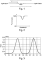
- Fig. 1 is a schematic representation of a fiber Bragg grating
- Fig. 2 is a conceptual plot of transmission versus wavelength illustrating a fiber Bragg grating transmission pattern mimicking an absorption dip at or near the select lasing frequency caused by a gas species of interest.
- Fig. 3 illustrates that a transmission pattern produced by a fiber Bragg grating and mimicking an absorption dip is repeatable.
- the scan on the left and right are mirror images of each other obtained by first increasing the laser wavelength toward longer wavelengths producing the indicated transmission pattern and then reversing the plot from longer wavelengths to shorter wavelengths.
- the spectrum is identical on the up and down scans and the peak occurs at exactly the same wavelength.
- Such a grating can be used as a system verification standard because the wavelength, amplitude and width of the peak do not change with time.
- the fiber Bragg grating could be used for calibrating a TDLAS system.
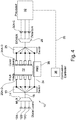
- Fig. 4 is a schematic representation of one embodiment of a TDLAS system including the method and apparatus for verification of proper operation.
- the TDLAS system as illustrated comprises three diode lasers 12A, 12B and 12C, each producing an output beam of a distinct select lasing frequency.
- select lasing frequency means a beam output having a narrow Gaussian spectral width with a peak at a specific lasing frequency, as is understood in the art.
- Each of the diode lasers 12A, 12B and 12C are optically coupled to a wavelength multiplexer 14 that combines the beams to a single multiplexed output beam 16.
- the multiplexed output beam 16 is optically coupled to a pitch side beam controller 18 configured to direct a beam of the multiplexed light to multiple pitch heads 20A-D.
- the pitch side beam controller is an optical switch having at least an output corresponding to each of the pitch heads 20A-D and the multiplexed beam 16 is selectively directed to each of the pitch heads 20A-D.
- the pitch side beam controller can be a beam splitter directing a portion of the beam to each of the outputs for coupling with the pitch heads 20A-D.
- the pitch heads 20A-D are configured to project at least a portion of the output beam of the diode lasers 12A-C through a process chamber 22 to a corresponding catch head 24A-D.
- Each of the catch heads 24A-D in turn is in optical communication with an input of a catch side beam controller 26 in the form of an optical switch for selectively communicating the various catch heads 24A-D with an output of the beam controller.
- the beam controller 26 in turn is coupled to a demultiplexer 28 which wavelength demultiplexes the beams according to wavelength and transmits portions of the various select lasing frequencies which in turn are optically coupled to corresponding detectors 30A-C.
- Each detector 30A-C is coupled to a processor 32. Electrical signals from each detector 30A-C are typically digitized and analyzed in processor 32. The digitized and analyzed data can be used to sense physical parameters within the process chamber including but not limited to the concentrations of various gas species and the combustion temperature within the process chamber.
- Embodiments could include the processor 32 being used to send signals through a feedback loop 35 to combustion controller 36 operatively associated with the process chamber and thereby actively control select process parameters within the process chamber 22.
- the sensing apparatus 10 is further provided with a FBG optical fiber 34 comprising a fiber Bragg grating configured to partially reflect a laser beam of a select lasing frequency produced by one of the diode lasers 12A-C.
- the remainder of the laser beam has an FBG transmission pattern mimicking the absorption dip at or near the select lasing frequency caused by a gas species characteristic of interest detected within the process chamber 22.
- Embodiments of the FBG optical fiber could include a plurality of fiber Bragg gratings in series, with each fiber Bragg grating being configured to partially reflect a laser beam of a discrete select lasing frequency produced by two or more of the diode lasers 12A-C.
- the remainder of the laser beam has an FBG transmission pattern mimicking the absorption dip at or near the select lasing frequency caused by a gas species characteristic of interest detected within the process chamber 22.
- the FBG optical fiber input is optically coupled to an output of the pitch side beam controller 18 and an output of the FBG optical fiber is coupled to an input of the catch side beam controller 26. In this manner the multiplexed beam 16 is passed through the FBG optical fiber in conjunction with the multiplexed beam 16 being passed through the to pitch heads 20A-D, the process chamber 22 and the catch heads 24A-D.
- the example of the sensing apparatus 10 illustrated in Fig. 4 could have more or less diode lasers and corresponding detectors and further could have more or less pitch head and catch head pairs and thus the sensing apparatus 10 is scalable to various applications.
- a single diode laser is provided which would obviate the need for the wavelength multiplexer 14 and demultiplexer 28 and in such an embodiment the FBG optical fiber 34 would require only a single fiber Bragg grating operative with the select lasing frequency of the single diode laser.
- Embodiments could also include a temperature control unit 38 for maintaining the FBG optical fiber 34 or the fiber Bragg gratings therein within a select temperature range to prevent substantial variation of the optical properties of each fiber Bragg grating in the FBG optical fiber.
- the temperature control unit could maintain the temperature of the fiber Bragg gratings to within plus or minus 0.278 degrees Celsius (plus or minus 0.5 degrees Fahrenheit).
- Embodiments could include the processor 32 being in communication with a combustion controller 36 to control combustion inputs such as fuel and air if the processor 32 detects combustion characteristics such as the concentration of gas phase species being monitored or temperature are deviating from necessary specifications. Such embodiments could also include the processor comparing the detected transmission patterns of the laser beams from the process chamber to that of the FBG absorption dips of the fiber Bragg gratings, with the processor producing a warning signal or even shutting down the combustion process in the event of an unacceptable deviation therebetween.
Landscapes
- Engineering & Computer Science (AREA)
- Chemical & Material Sciences (AREA)
- Physics & Mathematics (AREA)
- Analytical Chemistry (AREA)
- Spectroscopy & Molecular Physics (AREA)
- General Engineering & Computer Science (AREA)
- Mechanical Engineering (AREA)
- Combustion & Propulsion (AREA)
- Health & Medical Sciences (AREA)
- General Chemical & Material Sciences (AREA)
- Chemical Kinetics & Catalysis (AREA)
- Oil, Petroleum & Natural Gas (AREA)
- General Physics & Mathematics (AREA)
- General Health & Medical Sciences (AREA)
- Biochemistry (AREA)
- Optics & Photonics (AREA)
- Pathology (AREA)
- Immunology (AREA)
- Life Sciences & Earth Sciences (AREA)
- Biomedical Technology (AREA)
- Environmental & Geological Engineering (AREA)
- Investigating Or Analysing Materials By Optical Means (AREA)
- Optical Transform (AREA)
- Other Investigation Or Analysis Of Materials By Electrical Means (AREA)
- Financial Or Insurance-Related Operations Such As Payment And Settlement (AREA)
- Lasers (AREA)
Description
- This disclosure is directed to a Tunable Diode Laser Spectroscopy (TDLAS) system, and more particularly to an apparatus and method for verification of a TDLAS system operation.
- Tunable Diode Laser Spectroscopy (TDLAS) is widely used in both laboratory and industrial applications in which gas species characteristics, such as temperature or concentration, must be measured. A TDLAS system consists of one or more diode lasers each producing light at carefully controlled wavelengths which are projected into a process chamber to measure specific gas-phase molecules. Each laser's wavelength is typically tuned over a narrow wavelength interval encompassing the entire Gaussian spectral envelope, the envelope having a peak at a select wavelength (collectively referred to herein as a "select wavelength") and the amount of transmitted light across the select wavelength is measured. Gas phase species that absorb some of the light cause a dip in the amount of transmitted light as the wavelength is scanned (an "absorption dip") and quantification of the absorption dip allows one to calculate the concentration of the species with knowledge of the path length and a coefficient that describes the amount of light absorbed at a select wavelength and temperature. The absorption dip spectrum or pattern of a molecule can be thought of as a fingerprint. The pattern of absorption versus wavelength is a characteristic feature of each molecule and therefore TDLAS can be quite selective - detecting the species of interest in an environment rife with other molecules.
- One important application of TDLAS systems is for combustion monitoring and diagnostics. Combustion is used to drive many industrial processes from power generation to steel and glass production. Refineries and petrochemical plants use combustion to drive reactions toward completion. TDLAS systems have become quite complex in some cases, and they are being fielded for industrial applications in which process efficiency, reliability, and safety are paramount. Combustion species of interest include O2, CO, CO2 and H2O, all of which can be measured using TDLAS. In addition, temperature can be measured using line ratio techniques as known in the art. The TDLAS data can be used in a control loop to vary the fuel/air mixing ratio to optimize a combustion process efficiency while simultaneously insuring that safe operating conditions are maintained. Failure of, or erroneous results from, the TDLAS system when used for combustion optimization can have catastrophic results. To some extent, this problem can be mitigated via smart process control design; however, risk remains. As a consequence, a method of system calibration and system operation verification is desired to make sure that the TDLAS system is functioning properly and the data that is being generated is accurate and reliable.
- One known means of TDLAS system verification is to provide a gas-phase sample for the system to measure in an environment that mimics an environment in which measurements are being made. In the simplest of cases, a small, sealed spectroscopy cell with windows for the laser beam to pass through and a select gas species in the cell at the desired temperature, pressure and concentration can be used to verify that the system is measuring properly. However, for elevated combustion temperatures a sealed spectroscopy cell won't work well since the pressure will rise as the temperature rises and the details of the absorption spectrum are sensitive to pressure. In lieu of a sealed cell, a flowing cell can be used as a calibration and verification standard. The flowing cell can be heated to near combustion temperatures and gas mixtures approximating the combustion environment can be introduced. In practice, this type of system works well in a laboratory test environment and can be used for system validation. However, such a system represents a large investment of a minimum of tens of thousands of dollars. Furthermore, it is not portable or particularly user friendly. Most importantly, it would be extremely expensive to modify such a system for use outside a controlled laboratory environment.
-
WO 2007/041670 A1 andUS 2008/074645 A1 disclose a TDLAS sensing apparatus as defined in the preamble of claim 1.US 6,282,340 B1 discloses a laser diode module coupled to a pigtail optical fiber. A portion of the light generated by the laser diode module is branched by an optical coupler into an FBG optical fiber comprising a fiber Bragg grating formed in a core of the FBG optical fiber, the fiber Bragg grating being configured to partially reflect a laser beam of the select lasing frequency while passing the remainder of the laser beam to the FBG optical fiber output and to a photodiode. The output voltage of the photodiode is used in a feedback loop to lock the laser wavelength. A similar disclosure can be found inUS 6,058,131 A wherein two parallel FBG optical fibers, each with a different FBG, are used. - Needed is an inexpensive, durable and field deployable way to verify a TDLAS system is working properly and producing reliable results. The necessary TDLAS system and method must produce a reference absorption pattern or spectrum mimicking an absorption dip at or near the select lasing frequency of the gas species of interest. Frequent comparison of the reference transmission spectrum with the spectrum produced by the target species allows any changes to be noted. As long as the reference absorption spectrum does not change as a function of time or any other parameter, the comparison allows the user to determine the health of the system. The reference absorption spectrum should be produced by a package that is small, light and solid phase and does not change over time. Theoretically, one way of providing such a reference absorption pattern is a thin film filter which uses interference between many layers of varying refractive index and thickness to filter light in a given bandwidth. Although theoretically achievable, difficult and costly research and development would be necessary to make the thin-film filter concept a reality.
- The present invention is directed toward overcoming one or more of the problems discussed above.
- The invention is directed to a TDLAS sensing apparatus as defined in claim 1, the sensing apparatus comprising at least one diode laser producing an output beam of a first select lasing frequency coupled to an input of an optical fiber. A pitch side beam controller comprising at least one of a beam splitter or an optical switch has at least one input optically coupled to an output of the optical fiber and at least two outputs. At least one of the at least two outputs is optically coupled to a pitch optic operatively associated with a process chamber and oriented to project the output beam of the at least one diode laser through the process chamber. A catch is optic operatively associated with the process chamber in optical communication with the pitch optic to receive the output beam of the at least one diode laser projected through the process chamber. A catch side optical fiber is provided having an input side optically coupled to each catch optic and an output side. A catch side beam controller comprising an optical switch has at least two inputs and one output. The output side of the catch side optical fiber is optically coupled to one of the inputs. A detector is optically coupled to the beam controller output, the detector being sensitive to the select lasing frequency. An FBG optical fiber having an input and an output comprises at least one fiber Bragg grating formed in a core of the FBG optical fiber. The at least one fiber Bragg grating is configured to partially reflect a laser beam of the first select lasing frequency while passing at least a portion of the laser beam. The remainder of the laser beam has a FBG transmission pattern mimicking an absorption dip at or near the select lasing frequency caused by a gas species characteristic of interest. The FBG optical fiber input is optically coupled to another one of the at least two outputs of the pitch side beam controller and the FBG optical fiber output is optically coupled to an input of the catch side beam controller.
- Another aspect of the invention is a method of sensing gas species characteristics within a process chamber as defined in claim 7. The method includes the step of providing a process chamber and selectively projecting a beam of a first select lasing frequency though the process chamber. The beam projected through the process chamber is optically coupled to a detector sensitive to the select lasing frequency to detect a process transmission spectrum having an absorption dip at the select lasing frequency caused by a gas species characteristic of interest. The beam is also selectively projected through a fiber Bragg grating formed in a core of an optical fiber, the fiber Bragg grating being configured to partially reflect at least a portion of the laser beam of the first select lasing frequency while passing a remainder of the laser beam. The remainder of the laser beam has an FBG transmission spectrum mimicking the absorption dip at or near the select lasing frequency caused by a gas species characteristic of interest. The remainder of the laser beam is optically coupled the detector. Outputs of the detector are monitored to compare the FBG transmission spectrum to any process transmission spectrum produced in the process chamber.
- Fiber Bragg gratings offer the ability to produce an absorption dip at a specified wavelength, of a specified amplitude with a controllable spectral width in an extremely simple, lightweight package. The grating is written into the core of a single mode fiber, typically by exposing a mask created through a photolithography process with an excimer laser. The resulting periodic damage to the core creates a periodic refractive index variation that acts as a grating reflecting some wavelengths and transmitting others depending on the grating period, the scale of the refractive index variation and the amount of chirp in the grating (variation in period across the grating). Fiber Bragg gratings are used for a variety of purposes including: dispersion compensation in telecommunications systems, wavelength filtering in telecommunications (add/drop filters), and wavelength selection for fiber lasers among other uses. Unlike most wavelength selection/filtering applications, the present disclosure uses a fiber Bragg grating that is not 100% efficient. The fiber Bragg grating transmits 100% of the light outside a relevant bandwidth of the molecule of interest. However, within the relevant bandwidth, the FBG grating reflects a fraction of the incident light creating a facsimile of an absorption dip at or near the select lasing frequency caused by a gas species characteristic of interest.
- A further understanding of the nature and advantages of particular embodiments may be realized by reference to the remaining portions of the specification and the drawings, in which like reference numerals are used to refer to similar components. In some instances, a sub-label is associated with a reference numeral to denote one of multiple similar components. When reference is made to a reference numeral without specification to an existing sub-label, it is intended to refer to all such multiple similar components.
-
Fig. 1 is schematic representation of the effect of a fiber Bragg grating tuned to a select frequency in an optical fiber on a beam of laser light at the select frequency transmitted through the optical fiber; -
Fig. 2 is a conceptual plot of transmission versus wavelength illustrating a fiber Bragg grating as depicted inFig. 1 creating a transmission spectrum mimicking an absorption dip of a target molecule at or near the select lasing frequency range; -
Fig. 3 illustrates the repeatability of a transmission pattern of a fiber Bragg grating mimicking an absorption dip at a select lasing frequency caused by a gas species characteristic of interest; and -
Fig. 4 is schematic representation of an embodiment of a TDLAS system including the method and apparatus for verification of proper operation as disclosed herein. -
Fig. 1 is a schematic representation of a fiber Bragg grating andFig. 2 is a conceptual plot of transmission versus wavelength illustrating a fiber Bragg grating transmission pattern mimicking an absorption dip at or near the select lasing frequency caused by a gas species of interest. -
Fig. 3 illustrates that a transmission pattern produced by a fiber Bragg grating and mimicking an absorption dip is repeatable. The scan on the left and right are mirror images of each other obtained by first increasing the laser wavelength toward longer wavelengths producing the indicated transmission pattern and then reversing the plot from longer wavelengths to shorter wavelengths. The spectrum is identical on the up and down scans and the peak occurs at exactly the same wavelength. Such a grating can be used as a system verification standard because the wavelength, amplitude and width of the peak do not change with time. In addition to use for system verification, the fiber Bragg grating could be used for calibrating a TDLAS system. -
Fig. 4 is a schematic representation of one embodiment of a TDLAS system including the method and apparatus for verification of proper operation. The TDLAS system as illustrated comprises threediode lasers diode lasers wavelength multiplexer 14 that combines the beams to a single multiplexedoutput beam 16. The multiplexedoutput beam 16 is optically coupled to a pitchside beam controller 18 configured to direct a beam of the multiplexed light to multiple pitch heads 20A-D. In one embodiment the pitch side beam controller is an optical switch having at least an output corresponding to each of the pitch heads 20A-D and the multiplexedbeam 16 is selectively directed to each of the pitch heads 20A-D. In another embodiment, the pitch side beam controller can be a beam splitter directing a portion of the beam to each of the outputs for coupling with the pitch heads 20A-D. The pitch heads 20A-D are configured to project at least a portion of the output beam of thediode lasers 12A-C through a process chamber 22 to acorresponding catch head 24A-D. Each of the catch heads 24A-D in turn is in optical communication with an input of a catchside beam controller 26 in the form of an optical switch for selectively communicating the various catch heads 24A-D with an output of the beam controller. Thebeam controller 26 in turn is coupled to ademultiplexer 28 which wavelength demultiplexes the beams according to wavelength and transmits portions of the various select lasing frequencies which in turn are optically coupled tocorresponding detectors 30A-C. Eachdetector 30A-C is coupled to aprocessor 32. Electrical signals from eachdetector 30A-C are typically digitized and analyzed inprocessor 32. The digitized and analyzed data can be used to sense physical parameters within the process chamber including but not limited to the concentrations of various gas species and the combustion temperature within the process chamber. Embodiments could include theprocessor 32 being used to send signals through afeedback loop 35 tocombustion controller 36 operatively associated with the process chamber and thereby actively control select process parameters within the process chamber 22. - The
sensing apparatus 10 is further provided with a FBGoptical fiber 34 comprising a fiber Bragg grating configured to partially reflect a laser beam of a select lasing frequency produced by one of thediode lasers 12A-C. The remainder of the laser beam has an FBG transmission pattern mimicking the absorption dip at or near the select lasing frequency caused by a gas species characteristic of interest detected within the process chamber 22. Embodiments of the FBG optical fiber could include a plurality of fiber Bragg gratings in series, with each fiber Bragg grating being configured to partially reflect a laser beam of a discrete select lasing frequency produced by two or more of thediode lasers 12A-C. The remainder of the laser beam has an FBG transmission pattern mimicking the absorption dip at or near the select lasing frequency caused by a gas species characteristic of interest detected within the process chamber 22. In all embodiments the FBG optical fiber input is optically coupled to an output of the pitchside beam controller 18 and an output of the FBG optical fiber is coupled to an input of the catchside beam controller 26. In this manner the multiplexedbeam 16 is passed through the FBG optical fiber in conjunction with the multiplexedbeam 16 being passed through the to pitchheads 20A-D, the process chamber 22 and the catch heads 24A-D. - The example of the
sensing apparatus 10 illustrated inFig. 4 could have more or less diode lasers and corresponding detectors and further could have more or less pitch head and catch head pairs and thus thesensing apparatus 10 is scalable to various applications. At a bare minimum, a single diode laser is provided which would obviate the need for thewavelength multiplexer 14 anddemultiplexer 28 and in such an embodiment the FBGoptical fiber 34 would require only a single fiber Bragg grating operative with the select lasing frequency of the single diode laser. - Embodiments could also include a
temperature control unit 38 for maintaining the FBGoptical fiber 34 or the fiber Bragg gratings therein within a select temperature range to prevent substantial variation of the optical properties of each fiber Bragg grating in the FBG optical fiber. For example, the temperature control unit could maintain the temperature of the fiber Bragg gratings to within plus or minus 0.278 degrees Celsius (plus or minus 0.5 degrees Fahrenheit). - Embodiments could include the
processor 32 being in communication with acombustion controller 36 to control combustion inputs such as fuel and air if theprocessor 32 detects combustion characteristics such as the concentration of gas phase species being monitored or temperature are deviating from necessary specifications. Such embodiments could also include the processor comparing the detected transmission patterns of the laser beams from the process chamber to that of the FBG absorption dips of the fiber Bragg gratings, with the processor producing a warning signal or even shutting down the combustion process in the event of an unacceptable deviation therebetween. - Various modifications and additions can be made to the embodiments discussed without departing from the scope of the invention as defined by the appended claims.
Claims (13)
- A TDLAS sensing apparatus for sensing gas species characteristics within a process chamber, the sensing apparatus comprising:a pitch side optical fiber and at least one diode laser (12A, 12B, 12C) for producing an output beam of a select lasing frequency optically coupled to an input of the pitch side optical fiber;a pitch side beam controller (18) comprising at least one of a beam splitter or an optical switch, the pitch side beam controller (18) having at least one input optically coupled to an output of the pitch side optical fiber and at least two outputs;a pitch optic (20A-D) configured to be operatively associated with the process chamber (22) and oriented to project the output beam of the at least one diode laser (12A, 12B, 12C) through the process chamber (22), wherein at least one of the at least two outputs of the pitch side beam controller (18) is optically coupled to the pitch optic;a catch optic (24A-D) configured to be operatively associated with the process chamber (22) in optical communication with the pitch optic to receive the output beam of the at least one diode laser (12A, 12B, 12C) projected through the process chamber (22);a catch side optical fiber having an input side optically coupled to the catch optic and an output side;a catch side beam controller (26) comprising an optical switch having at least two inputs and one output, wherein the output side of the catch side optical fiber is optically coupled to an input of the catch side beam controller (26);a detector (30A-C) optically coupled to the catch side beam controller (26) output, the detector being sensitive to the select lasing frequency;characterized by an FBG optical fiber (34) having an input and an output, the FBG optical fiber comprising at least one fiber Bragg grating formed in a core of the FBG optical fiber, the at least one fiber Bragg grating being configured to partially reflect a laser beam of the select lasing frequency while passing the remainder of the laser beam to the FBG optical fiber output, the FBG optical fiber input being optically coupled to another one of the at least two outputs of the pitch side beam controller (18) and the FBG optical fiber output being optically coupled to another one of the at least two inputs of the catch side beam controller (26).
- The sensing apparatus of claim 1 further comprising:
a temperature control unit (38) operatively associated with the fiber Bragg grating of the FBG optical fiber to maintain the fiber Bragg grating at a select temperature range, the select temperature range preventing substantial variation of optical properties of each fiber Bragg grating. - The sensing apparatus of claim 2 wherein the select temperature range is plus or minus 0.278 degrees Celsius.
- The sensing apparatus of claim 1 comprising:a plurality of diode lasers (12A, 12B, 12C) each for producing an output beam of a distinct select lasing frequency each coupled to an input of a distinct pitch side optical fiber;a multiplexer (14) optically coupled to each distinct pitch side optical fiber output configured to combine the output beam of each of the plurality of diode lasers to a multiplexed beam (16);a demultiplexer (28) optically coupled to the output of the catch side beam controller (26) configured to separate each output beam by its distinct lasing frequency; anda plurality of detectors (30A-C) corresponding to the plurality of diode lasers each sensitive to the select lasing frequency of the corresponding diode laser.
- The sensing apparatus of claim 1 comprising a plurality of pitch optics (20A-D) each operatively associated with a distinct output of the pitch side beam controller (18) and a corresponding plurality of catch optics (24A-D) each optically coupled to a distinct input of the catch side beam controller (26).
- The sensing apparatus of claim 4 wherein the FBG optical fiber (34) comprises a plurality of fiber Bragg gratings in series, each fiber Bragg grating being configured to partially reflect a portion of a laser beam of a distinct select lasing frequency while passing the remainder of the laser beam to the FBG optical fiber output.
- A TDLAS based method of sensing gas species characteristics within a process chamber, the method comprising:providing a process chamber (22);selectively projecting a beam of a select lasing frequency though the process chamber (22);optically coupling the beam projected through the process chamber (22) to a detector (30A-C) sensitive to the select lasing frequency to detect an absorption dip at or near the select lasing frequency caused by a gas species characteristic of interest;characterized byselectively projecting the beam of the select lasing frequency through a fiber Bragg grating formed in a core of an FBG optical fiber (34), the fiber Bragg grating being configured to partially reflect a beam of the select lasing frequency while passing the remainder of the beam, the remainder of the beam mimicking an absorption dip at the select lasing frequency caused by a gas species characteristic of interest;optically coupling the remainder of the beam passing through the FBG optical fiber to the detector; andmonitoring an output of the detector to compare a transmission pattern of the FBG absorption dip to that produced in the process chamber (22).
- The method of claim 7 further comprising:
maintaining each fiber Bragg grating at a select temperature range, the select temperature range preventing substantial variation of optical properties of each fiber Bragg grating. - The method of claim 8 wherein the select temperature range is plus or minus 0.278 degrees Celsius.
- The method of claim 7 further comprising:selectively projecting a multiplexed plurality of beams each of a distinct select lasing frequency though the process chamber;selectively projecting the beam of multiplexed beams through the fiber Bragg grating formed in the core of the FBG optical fiber (34), the fiber Bragg grating being configured to partially reflect a beam of at least one select lasing frequency while passing the remainder of the beam, the remainder of the beam mimicking the absorption dip at the select lasing frequency caused by a gas species characteristic of interest;demultiplexing the multiplexed beams to separate each output beam by its distinct lasing frequency;optically coupling each demultiplexed beam to a detector (30A-C) sensitive to the select lasing frequency of the corresponding demultiplexed output beam; andmonitoring an output of the detector to compare a transmission pattern of the FBG absorption dip to that produced in the process chamber at the same select lasing frequency.
- The method of claim 10 further comprising providing a plurality of fiber Bragg gratings in series in the FBG optical fiber (34), each fiber Bragg grating being configured to partially reflect a portion of a laser beam of a distinct select lasing frequency while passing the remainder of the laser beam to the FBG optical fiber output; and
monitoring an output of the detector to compare the transmission pattern of each of the FBG absorption dips to that produced in the process chamber at the same distinct lasing frequency. - The method of claim 7 further comprising:
processing the output of the detector to sense physical parameters within the process chamber. - The method of claim 12 further comprising:
sending signals through a feedback loop to a combustion controller to control select physical parameters within the process chamber based on the processed output of the detector.
Applications Claiming Priority (2)
| Application Number | Priority Date | Filing Date | Title |
|---|---|---|---|
| US201662321634P | 2016-04-12 | 2016-04-12 | |
| PCT/US2017/023392 WO2017180297A1 (en) | 2016-04-12 | 2017-03-21 | Method and apparatus for verification of tdlas system operation |
Publications (3)
| Publication Number | Publication Date |
|---|---|
| EP3443325A1 EP3443325A1 (en) | 2019-02-20 |
| EP3443325A4 EP3443325A4 (en) | 2019-12-04 |
| EP3443325B1 true EP3443325B1 (en) | 2021-01-20 |
Family
ID=60041834
Family Applications (1)
| Application Number | Title | Priority Date | Filing Date |
|---|---|---|---|
| EP17782809.2A Active EP3443325B1 (en) | 2016-04-12 | 2017-03-21 | Method and apparatus for verification of tdlas system operation |
Country Status (11)
| Country | Link |
|---|---|
| US (1) | US10738997B2 (en) |
| EP (1) | EP3443325B1 (en) |
| JP (1) | JP6909804B2 (en) |
| KR (1) | KR102195472B1 (en) |
| CN (1) | CN109073548B (en) |
| AU (1) | AU2017251622B2 (en) |
| CA (1) | CA3020690A1 (en) |
| ES (1) | ES2853723T3 (en) |
| RU (1) | RU2730447C2 (en) |
| SG (1) | SG11201808029QA (en) |
| WO (1) | WO2017180297A1 (en) |
Family Cites Families (19)
| Publication number | Priority date | Publication date | Assignee | Title |
|---|---|---|---|---|
| DE19633569A1 (en) * | 1996-08-21 | 1998-02-26 | Inst Physikalische Hochtech Ev | Solid state laser light source wavelength control method |
| US6058131A (en) * | 1997-11-17 | 2000-05-02 | E-Tek Dynamics, Inc. | Wavelength stabilization of laser source using fiber Bragg grating feedback |
| US6282340B1 (en) * | 1998-04-23 | 2001-08-28 | The Furukawa Electric Co., Ltd. | Light wavelength tuning device and light source optical demultiplexer and wavelength division multiplexed optical communication system using the tuning device |
| AU1751701A (en) * | 1999-11-04 | 2001-05-14 | L'air Liquide, Societe Anonyme A Directoire Et Conseil De Surveillance Pour L'etude Et L'exploitation Des Procedes Georges Claude | Method for continuously monitoring chemical species and temperature in hot process gases |
| US6573489B1 (en) * | 2000-08-09 | 2003-06-03 | The United States Of America, As Represented By The Secretary Of The Navy | Passive, temperature compensated techniques for tunable filter calibration in bragg-grating interrogation systems |
| US6912237B2 (en) * | 2001-02-06 | 2005-06-28 | The Furukawa Electric Co., Ltd. | Semiconductor laser module and semiconductor laser device having light feedback function |
| US6748179B2 (en) * | 2001-03-07 | 2004-06-08 | Harris Corporation | WDM channel monitoring system and method |
| CN101408458A (en) * | 2003-03-31 | 2009-04-15 | 佐勒技术公司 | Method and device for monitoring and controlling combusting course |
| JP2008524577A (en) * | 2004-12-15 | 2008-07-10 | コーニンクレッカ フィリップス エレクトロニクス エヌ ヴィ | Method and apparatus for calibration of optical analytical markings using multivariate optical elements |
| US7787123B2 (en) * | 2005-10-04 | 2010-08-31 | Zolo Technologies, Inc. | Two line gas spectroscopy calibration |
| WO2008054429A2 (en) * | 2005-11-15 | 2008-05-08 | Zolo Technologies, Inc. | All-fiber architecture for an embedded flight sensor for aeropropulsion applications |
| JP5096975B2 (en) * | 2008-03-25 | 2012-12-12 | 大阪瓦斯株式会社 | Gas detector |
| US8964801B2 (en) * | 2009-06-11 | 2015-02-24 | Esi-Pyrophotonics Lasers, Inc. | Method and system for stable and tunable high power pulsed laser system |
| KR101201530B1 (en) * | 2009-07-28 | 2012-12-13 | 유티오인터내셔날코퍼레이션(영업소) | Hybrid electrical sensor with probation and correction functions for structure measuring instrument and method for generating a control voltage using the sensor |
| KR20110112086A (en) * | 2010-04-06 | 2011-10-12 | 주식회사 싸이트로닉 | High speed fiber optic grating sensor measurement instrument with variable laser method |
| CN102252704A (en) * | 2010-05-17 | 2011-11-23 | 北京派科森科技有限公司 | High-speed, high-precision and multi-channel Bragg grating demodulation device |
| CA2814356C (en) * | 2011-05-25 | 2018-03-27 | Fuji Electric Co., Ltd. | Light source device, analysis device, and light generation method |
| CN203519492U (en) * | 2013-09-02 | 2014-04-02 | 刘永宁 | Multi-channel multi-point gas detection system based on second harmonic detection technology |
| CN105136740A (en) * | 2015-10-26 | 2015-12-09 | 中国人民解放军军事医学科学院卫生装备研究所 | Temperature and humidify monitoring system based on TDLAS |
-
2017
- 2017-03-21 RU RU2018138564A patent/RU2730447C2/en active
- 2017-03-21 ES ES17782809T patent/ES2853723T3/en active Active
- 2017-03-21 WO PCT/US2017/023392 patent/WO2017180297A1/en not_active Ceased
- 2017-03-21 JP JP2018553189A patent/JP6909804B2/en not_active Expired - Fee Related
- 2017-03-21 KR KR1020187028968A patent/KR102195472B1/en not_active Expired - Fee Related
- 2017-03-21 AU AU2017251622A patent/AU2017251622B2/en not_active Ceased
- 2017-03-21 CA CA3020690A patent/CA3020690A1/en active Pending
- 2017-03-21 EP EP17782809.2A patent/EP3443325B1/en active Active
- 2017-03-21 SG SG11201808029QA patent/SG11201808029QA/en unknown
- 2017-03-21 CN CN201780023121.XA patent/CN109073548B/en not_active Expired - Fee Related
- 2017-03-21 US US16/092,992 patent/US10738997B2/en not_active Expired - Fee Related
Non-Patent Citations (1)
| Title |
|---|
| None * |
Also Published As
| Publication number | Publication date |
|---|---|
| US10738997B2 (en) | 2020-08-11 |
| KR20180134884A (en) | 2018-12-19 |
| KR102195472B1 (en) | 2020-12-29 |
| AU2017251622A1 (en) | 2018-10-11 |
| ES2853723T3 (en) | 2021-09-17 |
| CN109073548A (en) | 2018-12-21 |
| CN109073548B (en) | 2021-04-02 |
| RU2018138564A (en) | 2020-05-12 |
| AU2017251622B2 (en) | 2021-08-05 |
| JP6909804B2 (en) | 2021-07-28 |
| CA3020690A1 (en) | 2017-10-19 |
| RU2730447C2 (en) | 2020-08-21 |
| JP2019513998A (en) | 2019-05-30 |
| EP3443325A1 (en) | 2019-02-20 |
| WO2017180297A1 (en) | 2017-10-19 |
| EP3443325A4 (en) | 2019-12-04 |
| SG11201808029QA (en) | 2018-10-30 |
| US20190128520A1 (en) | 2019-05-02 |
| RU2018138564A3 (en) | 2020-06-03 |
Similar Documents
| Publication | Publication Date | Title |
|---|---|---|
| US10634608B2 (en) | Optical absorption spectroscopy based gas analyzer systems and methods | |
| EP3225962B1 (en) | Stabilisation system for a light source | |
| EP2380005B1 (en) | Method and device for measuring the concentration of substances in gaseous or fluid media through optical spectroscopy using broadband light sources | |
| AU2004227359B2 (en) | Method and apparatus for the monitoring and control of combustion | |
| US6707021B2 (en) | Transparent medium processing device | |
| US8154715B2 (en) | Method for monitoring and measuring optical properties of device in polarization maintaining fibers by using reference fiber bragg grating and fiber components manufactured thereby | |
| US9383272B2 (en) | Optical measurement system with polarization compensation, and corresponding method | |
| US12571725B2 (en) | Optical cavity-enhanced frequency comb spectroscopy | |
| US5991032A (en) | Contaminant identification and concentration determination by monitoring the intensity of the output of an intracavity laser | |
| US5999259A (en) | Contaminant identification and concentration determination by monitoring the wavelength, or intensity at a specific wavelength, of the output of an intracavity laser | |
| EP2587154A1 (en) | Method for data acquisition from a combustion process | |
| AU2017251622B2 (en) | Method and apparatus for verification of TDLAS system operation | |
| JP4853255B2 (en) | Gas analyzer | |
| D’Agostino et al. | A monolithically integrated AWG based wavelength interrogator with 180 nm working range and pm resolution | |
| US7646951B2 (en) | Apparatus for manufacturing optical fiber Bragg grating, optical fiber, and mid-infrared optical fiber laser | |
| US20250015552A1 (en) | High-power diode laser system | |
| RU2838849C1 (en) | Multichannel method of polling fibre bragg gratings | |
| US20210296848A1 (en) | Laser diagnostics apparatus | |
| Belikin et al. | Method for spectral interrogation of the fiber bragg gratings using a tunable narrowband light source | |
| Falciai et al. | Fibre Bragg grating location and spatial period determination in DBR lasers by side-scatter detection of pump radiation |
Legal Events
| Date | Code | Title | Description |
|---|---|---|---|
| STAA | Information on the status of an ep patent application or granted ep patent |
Free format text: STATUS: THE INTERNATIONAL PUBLICATION HAS BEEN MADE |
|
| PUAI | Public reference made under article 153(3) epc to a published international application that has entered the european phase |
Free format text: ORIGINAL CODE: 0009012 |
|
| STAA | Information on the status of an ep patent application or granted ep patent |
Free format text: STATUS: REQUEST FOR EXAMINATION WAS MADE |
|
| 17P | Request for examination filed |
Effective date: 20181112 |
|
| AK | Designated contracting states |
Kind code of ref document: A1 Designated state(s): AL AT BE BG CH CY CZ DE DK EE ES FI FR GB GR HR HU IE IS IT LI LT LU LV MC MK MT NL NO PL PT RO RS SE SI SK SM TR |
|
| AX | Request for extension of the european patent |
Extension state: BA ME |
|
| DAV | Request for validation of the european patent (deleted) | ||
| DAX | Request for extension of the european patent (deleted) | ||
| A4 | Supplementary search report drawn up and despatched |
Effective date: 20191105 |
|
| RIC1 | Information provided on ipc code assigned before grant |
Ipc: G01N 21/27 20060101ALN20191029BHEP Ipc: B01D 53/30 20060101ALI20191029BHEP Ipc: G01N 21/39 20060101AFI20191029BHEP Ipc: F23N 5/00 20060101ALI20191029BHEP |
|
| RIC1 | Information provided on ipc code assigned before grant |
Ipc: G01N 21/39 20060101AFI20200709BHEP Ipc: F23N 5/00 20060101ALI20200709BHEP Ipc: G01N 21/27 20060101ALN20200709BHEP Ipc: B01D 53/30 20060101ALI20200709BHEP |
|
| GRAP | Despatch of communication of intention to grant a patent |
Free format text: ORIGINAL CODE: EPIDOSNIGR1 |
|
| STAA | Information on the status of an ep patent application or granted ep patent |
Free format text: STATUS: GRANT OF PATENT IS INTENDED |
|
| INTG | Intention to grant announced |
Effective date: 20200814 |
|
| GRAS | Grant fee paid |
Free format text: ORIGINAL CODE: EPIDOSNIGR3 |
|
| GRAA | (expected) grant |
Free format text: ORIGINAL CODE: 0009210 |
|
| STAA | Information on the status of an ep patent application or granted ep patent |
Free format text: STATUS: THE PATENT HAS BEEN GRANTED |
|
| RAP1 | Party data changed (applicant data changed or rights of an application transferred) |
Owner name: ONPOINT TECHNOLOGIES, LLC |
|
| AK | Designated contracting states |
Kind code of ref document: B1 Designated state(s): AL AT BE BG CH CY CZ DE DK EE ES FI FR GB GR HR HU IE IS IT LI LT LU LV MC MK MT NL NO PL PT RO RS SE SI SK SM TR |
|
| REG | Reference to a national code |
Ref country code: GB Ref legal event code: FG4D |
|
| REG | Reference to a national code |
Ref country code: CH Ref legal event code: EP |
|
| REG | Reference to a national code |
Ref country code: DE Ref legal event code: R096 Ref document number: 602017031727 Country of ref document: DE |
|
| REG | Reference to a national code |
Ref country code: AT Ref legal event code: REF Ref document number: 1356825 Country of ref document: AT Kind code of ref document: T Effective date: 20210215 |
|
| REG | Reference to a national code |
Ref country code: IE Ref legal event code: FG4D |
|
| REG | Reference to a national code |
Ref country code: NL Ref legal event code: FP |
|
| REG | Reference to a national code |
Ref country code: LT Ref legal event code: MG9D |
|
| REG | Reference to a national code |
Ref country code: AT Ref legal event code: MK05 Ref document number: 1356825 Country of ref document: AT Kind code of ref document: T Effective date: 20210120 |
|
| PG25 | Lapsed in a contracting state [announced via postgrant information from national office to epo] |
Ref country code: LT Free format text: LAPSE BECAUSE OF FAILURE TO SUBMIT A TRANSLATION OF THE DESCRIPTION OR TO PAY THE FEE WITHIN THE PRESCRIBED TIME-LIMIT Effective date: 20210120 Ref country code: BG Free format text: LAPSE BECAUSE OF FAILURE TO SUBMIT A TRANSLATION OF THE DESCRIPTION OR TO PAY THE FEE WITHIN THE PRESCRIBED TIME-LIMIT Effective date: 20210420 Ref country code: GR Free format text: LAPSE BECAUSE OF FAILURE TO SUBMIT A TRANSLATION OF THE DESCRIPTION OR TO PAY THE FEE WITHIN THE PRESCRIBED TIME-LIMIT Effective date: 20210421 Ref country code: HR Free format text: LAPSE BECAUSE OF FAILURE TO SUBMIT A TRANSLATION OF THE DESCRIPTION OR TO PAY THE FEE WITHIN THE PRESCRIBED TIME-LIMIT Effective date: 20210120 Ref country code: FI Free format text: LAPSE BECAUSE OF FAILURE TO SUBMIT A TRANSLATION OF THE DESCRIPTION OR TO PAY THE FEE WITHIN THE PRESCRIBED TIME-LIMIT Effective date: 20210120 Ref country code: NO Free format text: LAPSE BECAUSE OF FAILURE TO SUBMIT A TRANSLATION OF THE DESCRIPTION OR TO PAY THE FEE WITHIN THE PRESCRIBED TIME-LIMIT Effective date: 20210420 Ref country code: PT Free format text: LAPSE BECAUSE OF FAILURE TO SUBMIT A TRANSLATION OF THE DESCRIPTION OR TO PAY THE FEE WITHIN THE PRESCRIBED TIME-LIMIT Effective date: 20210520 |
|
| PG25 | Lapsed in a contracting state [announced via postgrant information from national office to epo] |
Ref country code: AT Free format text: LAPSE BECAUSE OF FAILURE TO SUBMIT A TRANSLATION OF THE DESCRIPTION OR TO PAY THE FEE WITHIN THE PRESCRIBED TIME-LIMIT Effective date: 20210120 Ref country code: RS Free format text: LAPSE BECAUSE OF FAILURE TO SUBMIT A TRANSLATION OF THE DESCRIPTION OR TO PAY THE FEE WITHIN THE PRESCRIBED TIME-LIMIT Effective date: 20210120 Ref country code: LV Free format text: LAPSE BECAUSE OF FAILURE TO SUBMIT A TRANSLATION OF THE DESCRIPTION OR TO PAY THE FEE WITHIN THE PRESCRIBED TIME-LIMIT Effective date: 20210120 Ref country code: PL Free format text: LAPSE BECAUSE OF FAILURE TO SUBMIT A TRANSLATION OF THE DESCRIPTION OR TO PAY THE FEE WITHIN THE PRESCRIBED TIME-LIMIT Effective date: 20210120 Ref country code: SE Free format text: LAPSE BECAUSE OF FAILURE TO SUBMIT A TRANSLATION OF THE DESCRIPTION OR TO PAY THE FEE WITHIN THE PRESCRIBED TIME-LIMIT Effective date: 20210120 |
|
| REG | Reference to a national code |
Ref country code: ES Ref legal event code: FG2A Ref document number: 2853723 Country of ref document: ES Kind code of ref document: T3 Effective date: 20210917 |
|
| PG25 | Lapsed in a contracting state [announced via postgrant information from national office to epo] |
Ref country code: IS Free format text: LAPSE BECAUSE OF FAILURE TO SUBMIT A TRANSLATION OF THE DESCRIPTION OR TO PAY THE FEE WITHIN THE PRESCRIBED TIME-LIMIT Effective date: 20210520 |
|
| REG | Reference to a national code |
Ref country code: DE Ref legal event code: R097 Ref document number: 602017031727 Country of ref document: DE |
|
| PG25 | Lapsed in a contracting state [announced via postgrant information from national office to epo] |
Ref country code: SM Free format text: LAPSE BECAUSE OF FAILURE TO SUBMIT A TRANSLATION OF THE DESCRIPTION OR TO PAY THE FEE WITHIN THE PRESCRIBED TIME-LIMIT Effective date: 20210120 Ref country code: EE Free format text: LAPSE BECAUSE OF FAILURE TO SUBMIT A TRANSLATION OF THE DESCRIPTION OR TO PAY THE FEE WITHIN THE PRESCRIBED TIME-LIMIT Effective date: 20210120 Ref country code: CZ Free format text: LAPSE BECAUSE OF FAILURE TO SUBMIT A TRANSLATION OF THE DESCRIPTION OR TO PAY THE FEE WITHIN THE PRESCRIBED TIME-LIMIT Effective date: 20210120 Ref country code: MC Free format text: LAPSE BECAUSE OF FAILURE TO SUBMIT A TRANSLATION OF THE DESCRIPTION OR TO PAY THE FEE WITHIN THE PRESCRIBED TIME-LIMIT Effective date: 20210120 |
|
| REG | Reference to a national code |
Ref country code: CH Ref legal event code: PL |
|
| PLBE | No opposition filed within time limit |
Free format text: ORIGINAL CODE: 0009261 |
|
| STAA | Information on the status of an ep patent application or granted ep patent |
Free format text: STATUS: NO OPPOSITION FILED WITHIN TIME LIMIT |
|
| PG25 | Lapsed in a contracting state [announced via postgrant information from national office to epo] |
Ref country code: RO Free format text: LAPSE BECAUSE OF FAILURE TO SUBMIT A TRANSLATION OF THE DESCRIPTION OR TO PAY THE FEE WITHIN THE PRESCRIBED TIME-LIMIT Effective date: 20210120 Ref country code: DK Free format text: LAPSE BECAUSE OF FAILURE TO SUBMIT A TRANSLATION OF THE DESCRIPTION OR TO PAY THE FEE WITHIN THE PRESCRIBED TIME-LIMIT Effective date: 20210120 Ref country code: SK Free format text: LAPSE BECAUSE OF FAILURE TO SUBMIT A TRANSLATION OF THE DESCRIPTION OR TO PAY THE FEE WITHIN THE PRESCRIBED TIME-LIMIT Effective date: 20210120 |
|
| REG | Reference to a national code |
Ref country code: BE Ref legal event code: MM Effective date: 20210331 |
|
| 26N | No opposition filed |
Effective date: 20211021 |
|
| PG25 | Lapsed in a contracting state [announced via postgrant information from national office to epo] |
Ref country code: IE Free format text: LAPSE BECAUSE OF NON-PAYMENT OF DUE FEES Effective date: 20210321 Ref country code: LI Free format text: LAPSE BECAUSE OF NON-PAYMENT OF DUE FEES Effective date: 20210331 Ref country code: LU Free format text: LAPSE BECAUSE OF NON-PAYMENT OF DUE FEES Effective date: 20210321 Ref country code: CH Free format text: LAPSE BECAUSE OF NON-PAYMENT OF DUE FEES Effective date: 20210331 Ref country code: AL Free format text: LAPSE BECAUSE OF FAILURE TO SUBMIT A TRANSLATION OF THE DESCRIPTION OR TO PAY THE FEE WITHIN THE PRESCRIBED TIME-LIMIT Effective date: 20210120 |
|
| PG25 | Lapsed in a contracting state [announced via postgrant information from national office to epo] |
Ref country code: SI Free format text: LAPSE BECAUSE OF FAILURE TO SUBMIT A TRANSLATION OF THE DESCRIPTION OR TO PAY THE FEE WITHIN THE PRESCRIBED TIME-LIMIT Effective date: 20210120 |
|
| PG25 | Lapsed in a contracting state [announced via postgrant information from national office to epo] |
Ref country code: IS Free format text: LAPSE BECAUSE OF FAILURE TO SUBMIT A TRANSLATION OF THE DESCRIPTION OR TO PAY THE FEE WITHIN THE PRESCRIBED TIME-LIMIT Effective date: 20210520 |
|
| PG25 | Lapsed in a contracting state [announced via postgrant information from national office to epo] |
Ref country code: BE Free format text: LAPSE BECAUSE OF NON-PAYMENT OF DUE FEES Effective date: 20210331 |
|
| PGFP | Annual fee paid to national office [announced via postgrant information from national office to epo] |
Ref country code: NL Payment date: 20230215 Year of fee payment: 7 |
|
| PGFP | Annual fee paid to national office [announced via postgrant information from national office to epo] |
Ref country code: FR Payment date: 20230208 Year of fee payment: 7 |
|
| PGFP | Annual fee paid to national office [announced via postgrant information from national office to epo] |
Ref country code: TR Payment date: 20230320 Year of fee payment: 7 Ref country code: IT Payment date: 20230213 Year of fee payment: 7 Ref country code: GB Payment date: 20230126 Year of fee payment: 7 Ref country code: DE Payment date: 20230125 Year of fee payment: 7 |
|
| PG25 | Lapsed in a contracting state [announced via postgrant information from national office to epo] |
Ref country code: CY Free format text: LAPSE BECAUSE OF FAILURE TO SUBMIT A TRANSLATION OF THE DESCRIPTION OR TO PAY THE FEE WITHIN THE PRESCRIBED TIME-LIMIT Effective date: 20210120 |
|
| P01 | Opt-out of the competence of the unified patent court (upc) registered |
Effective date: 20230528 |
|
| PG25 | Lapsed in a contracting state [announced via postgrant information from national office to epo] |
Ref country code: HU Free format text: LAPSE BECAUSE OF FAILURE TO SUBMIT A TRANSLATION OF THE DESCRIPTION OR TO PAY THE FEE WITHIN THE PRESCRIBED TIME-LIMIT; INVALID AB INITIO Effective date: 20170321 |
|
| PGFP | Annual fee paid to national office [announced via postgrant information from national office to epo] |
Ref country code: ES Payment date: 20230405 Year of fee payment: 7 |
|
| PG25 | Lapsed in a contracting state [announced via postgrant information from national office to epo] |
Ref country code: MK Free format text: LAPSE BECAUSE OF FAILURE TO SUBMIT A TRANSLATION OF THE DESCRIPTION OR TO PAY THE FEE WITHIN THE PRESCRIBED TIME-LIMIT Effective date: 20210120 |
|
| PG25 | Lapsed in a contracting state [announced via postgrant information from national office to epo] |
Ref country code: MT Free format text: LAPSE BECAUSE OF FAILURE TO SUBMIT A TRANSLATION OF THE DESCRIPTION OR TO PAY THE FEE WITHIN THE PRESCRIBED TIME-LIMIT Effective date: 20210120 |
|
| REG | Reference to a national code |
Ref country code: DE Ref legal event code: R119 Ref document number: 602017031727 Country of ref document: DE |
|
| REG | Reference to a national code |
Ref country code: NL Ref legal event code: MM Effective date: 20240401 |
|
| GBPC | Gb: european patent ceased through non-payment of renewal fee |
Effective date: 20240321 |
|
| PG25 | Lapsed in a contracting state [announced via postgrant information from national office to epo] |
Ref country code: NL Free format text: LAPSE BECAUSE OF NON-PAYMENT OF DUE FEES Effective date: 20240401 |
|
| PG25 | Lapsed in a contracting state [announced via postgrant information from national office to epo] |
Ref country code: NL Free format text: LAPSE BECAUSE OF NON-PAYMENT OF DUE FEES Effective date: 20240401 |
|
| PG25 | Lapsed in a contracting state [announced via postgrant information from national office to epo] |
Ref country code: DE Free format text: LAPSE BECAUSE OF NON-PAYMENT OF DUE FEES Effective date: 20241001 |
|
| PG25 | Lapsed in a contracting state [announced via postgrant information from national office to epo] |
Ref country code: GB Free format text: LAPSE BECAUSE OF NON-PAYMENT OF DUE FEES Effective date: 20240321 |
|
| PG25 | Lapsed in a contracting state [announced via postgrant information from national office to epo] |
Ref country code: FR Free format text: LAPSE BECAUSE OF NON-PAYMENT OF DUE FEES Effective date: 20240331 |
|
| PG25 | Lapsed in a contracting state [announced via postgrant information from national office to epo] |
Ref country code: GB Free format text: LAPSE BECAUSE OF NON-PAYMENT OF DUE FEES Effective date: 20240321 Ref country code: FR Free format text: LAPSE BECAUSE OF NON-PAYMENT OF DUE FEES Effective date: 20240331 Ref country code: DE Free format text: LAPSE BECAUSE OF NON-PAYMENT OF DUE FEES Effective date: 20241001 |
|
| PG25 | Lapsed in a contracting state [announced via postgrant information from national office to epo] |
Ref country code: IT Free format text: LAPSE BECAUSE OF NON-PAYMENT OF DUE FEES Effective date: 20240321 |
|
| REG | Reference to a national code |
Ref country code: ES Ref legal event code: FD2A Effective date: 20250506 |
|
| PG25 | Lapsed in a contracting state [announced via postgrant information from national office to epo] |
Ref country code: ES Free format text: LAPSE BECAUSE OF NON-PAYMENT OF DUE FEES Effective date: 20240322 |