EP3442646B1 - Blocking mechanism for a stopcock manifold - Google Patents
Blocking mechanism for a stopcock manifold Download PDFInfo
- Publication number
- EP3442646B1 EP3442646B1 EP17708840.8A EP17708840A EP3442646B1 EP 3442646 B1 EP3442646 B1 EP 3442646B1 EP 17708840 A EP17708840 A EP 17708840A EP 3442646 B1 EP3442646 B1 EP 3442646B1
- Authority
- EP
- European Patent Office
- Prior art keywords
- ramp
- latch
- tap
- coupling part
- coupling
- Prior art date
- Legal status (The legal status is an assumption and is not a legal conclusion. Google has not performed a legal analysis and makes no representation as to the accuracy of the status listed.)
- Active
Links
- 230000000903 blocking effect Effects 0.000 title claims description 8
- 230000008878 coupling Effects 0.000 claims description 39
- 238000010168 coupling process Methods 0.000 claims description 39
- 238000005859 coupling reaction Methods 0.000 claims description 39
- 238000003780 insertion Methods 0.000 description 4
- 230000037431 insertion Effects 0.000 description 4
- 239000012530 fluid Substances 0.000 description 2
- 239000007789 gas Substances 0.000 description 2
- 239000007788 liquid Substances 0.000 description 2
- 208000031968 Cadaver Diseases 0.000 description 1
- 241001080024 Telles Species 0.000 description 1
- 210000001072 colon Anatomy 0.000 description 1
- 230000005484 gravity Effects 0.000 description 1
- 238000012423 maintenance Methods 0.000 description 1
- 239000000463 material Substances 0.000 description 1
- 230000013011 mating Effects 0.000 description 1
- 238000000034 method Methods 0.000 description 1
- 230000002285 radioactive effect Effects 0.000 description 1
- 229940121896 radiopharmaceutical Drugs 0.000 description 1
- 239000012217 radiopharmaceutical Substances 0.000 description 1
- 230000002799 radiopharmaceutical effect Effects 0.000 description 1
Images


Classifications
-
- A—HUMAN NECESSITIES
- A61—MEDICAL OR VETERINARY SCIENCE; HYGIENE
- A61M—DEVICES FOR INTRODUCING MEDIA INTO, OR ONTO, THE BODY; DEVICES FOR TRANSDUCING BODY MEDIA OR FOR TAKING MEDIA FROM THE BODY; DEVICES FOR PRODUCING OR ENDING SLEEP OR STUPOR
- A61M39/00—Tubes, tube connectors, tube couplings, valves, access sites or the like, specially adapted for medical use
- A61M39/22—Valves or arrangement of valves
-
- F—MECHANICAL ENGINEERING; LIGHTING; HEATING; WEAPONS; BLASTING
- F16—ENGINEERING ELEMENTS AND UNITS; GENERAL MEASURES FOR PRODUCING AND MAINTAINING EFFECTIVE FUNCTIONING OF MACHINES OR INSTALLATIONS; THERMAL INSULATION IN GENERAL
- F16K—VALVES; TAPS; COCKS; ACTUATING-FLOATS; DEVICES FOR VENTING OR AERATING
- F16K31/00—Actuating devices; Operating means; Releasing devices
- F16K31/44—Mechanical actuating means
- F16K31/52—Mechanical actuating means with crank, eccentric, or cam
- F16K31/522—Mechanical actuating means with crank, eccentric, or cam comprising a tap or cock
-
- A—HUMAN NECESSITIES
- A61—MEDICAL OR VETERINARY SCIENCE; HYGIENE
- A61M—DEVICES FOR INTRODUCING MEDIA INTO, OR ONTO, THE BODY; DEVICES FOR TRANSDUCING BODY MEDIA OR FOR TAKING MEDIA FROM THE BODY; DEVICES FOR PRODUCING OR ENDING SLEEP OR STUPOR
- A61M39/00—Tubes, tube connectors, tube couplings, valves, access sites or the like, specially adapted for medical use
- A61M39/22—Valves or arrangement of valves
- A61M39/223—Multiway valves
-
- F—MECHANICAL ENGINEERING; LIGHTING; HEATING; WEAPONS; BLASTING
- F16—ENGINEERING ELEMENTS AND UNITS; GENERAL MEASURES FOR PRODUCING AND MAINTAINING EFFECTIVE FUNCTIONING OF MACHINES OR INSTALLATIONS; THERMAL INSULATION IN GENERAL
- F16K—VALVES; TAPS; COCKS; ACTUATING-FLOATS; DEVICES FOR VENTING OR AERATING
- F16K11/00—Multiple-way valves, e.g. mixing valves; Pipe fittings incorporating such valves
- F16K11/10—Multiple-way valves, e.g. mixing valves; Pipe fittings incorporating such valves with two or more closure members not moving as a unit
- F16K11/20—Multiple-way valves, e.g. mixing valves; Pipe fittings incorporating such valves with two or more closure members not moving as a unit operated by separate actuating members
- F16K11/22—Multiple-way valves, e.g. mixing valves; Pipe fittings incorporating such valves with two or more closure members not moving as a unit operated by separate actuating members with an actuating member for each valve, e.g. interconnected to form multiple-way valves
-
- F—MECHANICAL ENGINEERING; LIGHTING; HEATING; WEAPONS; BLASTING
- F16—ENGINEERING ELEMENTS AND UNITS; GENERAL MEASURES FOR PRODUCING AND MAINTAINING EFFECTIVE FUNCTIONING OF MACHINES OR INSTALLATIONS; THERMAL INSULATION IN GENERAL
- F16K—VALVES; TAPS; COCKS; ACTUATING-FLOATS; DEVICES FOR VENTING OR AERATING
- F16K5/00—Plug valves; Taps or cocks comprising only cut-off apparatus having at least one of the sealing faces shaped as a more or less complete surface of a solid of revolution, the opening and closing movement being predominantly rotary
- F16K5/04—Plug valves; Taps or cocks comprising only cut-off apparatus having at least one of the sealing faces shaped as a more or less complete surface of a solid of revolution, the opening and closing movement being predominantly rotary with plugs having cylindrical surfaces; Packings therefor
-
- A—HUMAN NECESSITIES
- A61—MEDICAL OR VETERINARY SCIENCE; HYGIENE
- A61M—DEVICES FOR INTRODUCING MEDIA INTO, OR ONTO, THE BODY; DEVICES FOR TRANSDUCING BODY MEDIA OR FOR TAKING MEDIA FROM THE BODY; DEVICES FOR PRODUCING OR ENDING SLEEP OR STUPOR
- A61M39/00—Tubes, tube connectors, tube couplings, valves, access sites or the like, specially adapted for medical use
- A61M39/22—Valves or arrangement of valves
- A61M2039/229—Stopcocks
Definitions
- the present invention relates to a mechanism for holding or blocking a ramp of taps or of individual taps on couplings of mechanized actuators, for example rotary, automated or not.
- Called tap ramp (s) (in English: "stopcock manifold valve") a component, made of any material, consists of a rail body provided with inlet / outlet connections of fluid, liquid or gas, wherein one or more taps are included . This type of component is often designed to be for single use.
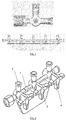
- FIG. 1 shows a valve ramp body 1 with inlet / outlet connections 3, on which are mounted three taps 2, each having at least one tap finger or crankpin 4 (here in this case three). See for example www.nordsonmedical.com, US 2011/0011474 A1 , etc.
- the principle consists in coupling the valves with rotary actuators, by means of coupling parts adapted to the shape of the crank pins of the valves which serve to transmit the rotational movement to the valve.
- valve rail Whether the valve rail is placed horizontally or vertically, it does not spontaneously hold in place in the couplings due to the forces of gravity and the movements transmitted to the valves by the couplings when they are actuated. It should therefore be kept in place by means of one or other suitable device.
- valve rails are of various commercial origins and have variable shapes and sizes. There is therefore no known universal fixing / blocking mechanism.
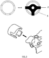
- a solution usually adopted consists in inserting the taps 2 into rotary couplings with open notches 5 (with or without centering) and in maintaining the valve ramp 7 in the notches by means of a latch 6 actuated manually or automatically and which maintains the ramp as a whole.
- the figure 4 shows respectively the steps of insertion (A) of the valve ramp 7 in the open notched couplings 5, of actuation of the latch 6 (B) and of obtaining the locked position of the ramp (C).
- the taps are not directly held by the couplings themselves, but by means of holding pieces for the whole of the boom, often bulky and not always guaranteeing the absolute insertion of each valve pin in its mating.
- valve rails mounted on devices marketed in the pharmaceutical and medical field there are often supports located at the front of the valve rail, such as knobs, allowing blocking in the direction of the axis of the taps.
- the holding mechanism then often consists of a movable plate which can either move along the axis of the valves, or be retractable by pivoting.
- FIG. 5 Another example of a holding mechanism, shown in the figure 5 , is mounted on a device marketed by the applicant (TRASIS UniDose TM).
- the present invention aims to provide a device which overcomes the disadvantages of the prior art.
- the invention aims to ensure easy placement of a valve ramp and allow the maintenance or blocking of this ramp reliably in the position of use.
- the invention also aims to propose an original solution for holding a valve ramp in place, directly integrated into the couplings themselves.
- the invention also aims to provide a mechanism where each coupling maintains its own valve.
- the normal position of use of the valve rail is the vertical position, that is to say corresponding to a vertical flow.
- the “front” position of the ramp indicates a position proximal to the device and the “rear” position of the ramp indicates a position distal of the device.
- one of the open notches of the coupling parts is replaced by a closed notch.
- the edge of the notch will act as a stop and will prevent, near the device, any movement of return of the crank pin away from the 'device (stop "front”).
- the other fulcrum will be the end of the latch which pushes on a rear part of the ramp ("rear" stop), which prevents, at a distance from the device, any movement of the ramp while approaching of the device.
- the colon support are in separate and opposite positions, no couple can tilt / rotate the ramp, making it impossible to remove it as it is.
- the invention consists in the implementation of a principle for holding the ramps of taps on the actuation mechanism in which the taps are individually held in their coupling.
- the fitting of the valve rail is done in a single simple movement.
Description
La présente invention se rapporte à un mécanisme de maintien ou de blocage d'une rampe de robinets ou de robinets individuels sur des accouplements d'actionneurs mécanisés, par exemple rotatifs, automatisés ou non.The present invention relates to a mechanism for holding or blocking a ramp of taps or of individual taps on couplings of mechanized actuators, for example rotary, automated or not.
On appelle rampe de robinet(s) (en anglais : « stopcock valve manifold ») un composant, réalisé en matière quelconque, constitué d'un corps de rampe muni de raccords d'entrée/sortie de fluide, liquide ou gaz, dans lequel sont inclus un ou plusieurs robinets. Ce type de composant est souvent conçu pour être à usage unique.Called tap ramp (s) (in English: "stopcock manifold valve") a component, made of any material, consists of a rail body provided with inlet / outlet connections of fluid, liquid or gas, wherein one or more taps are included . This type of component is often designed to be for single use.
Il s'agit notamment d'un composant permettant, moyennant un actionnement manuel ou automatisé du (des) robinet(s), de gérer des flux de liquides et/ou de gaz dans le cadre de manipulations généralement associées aux domaines pharmaceutique et médical.It is in particular a component making it possible, by manual or automated actuation of the tap (s), to manage flows of liquids and / or gases within the framework of manipulations generally associated with the pharmaceutical and medical fields.
Des exemples sont montrés sur les
Des dispositifs d'actionnement mécanisé, automatisés ou non, des robinets de rampes de robinets ont été mis sur le marché dans divers domaines d'application, notamment en chimie radio-pharmaceutique afin de :
- protéger l'opérateur d'éventuels dangers, par exemple lorsque certains fluides sont radioactifs ;
- faciliter la tâche de l'opérateur, les robinets étant actionnées par des moteurs ou des vérins ;
- sécuriser des procédés qui peuvent inclure des séquences d'actionnement complexes.
- protect the operator from possible dangers, for example when certain fluids are radioactive;
- facilitate the operator's task, the valves being actuated by motors or jacks;
- secure processes which may include complex actuation sequences.
Quel que soit le champ d'application, le principe consiste à accoupler les robinets avec des actionneurs rotatifs, par l'intermédiaire de pièces d'accouplement adaptées à la forme des manetons des robinets qui servent à transmettre le mouvement de rotation au robinet.Whatever the field of application, the principle consists in coupling the valves with rotary actuators, by means of coupling parts adapted to the shape of the crank pins of the valves which serve to transmit the rotational movement to the valve.
Que la rampe de robinet soit placée horizontalement ou verticalement, elle ne tient pas spontanément en place dans les accouplements à cause des forces de gravité et des mouvements transmis aux robinets par les accouplements lors de leur actionnement. Il convient donc de la maintenir en place au moyen de l'un ou l'autre dispositif adéquat.Whether the valve rail is placed horizontally or vertically, it does not spontaneously hold in place in the couplings due to the forces of gravity and the movements transmitted to the valves by the couplings when they are actuated. It should therefore be kept in place by means of one or other suitable device.
Les rampes de robinets sont de diverses origines commerciales et ont des formes et dimensions variables. On ne connaît donc pas de mécanisme de fixation/blocage universel.The valve rails are of various commercial origins and have variable shapes and sizes. There is therefore no known universal fixing / blocking mechanism.
Comme représenté sur les
L'opérateur doit donc effectuer le placement de la rampe de robinets en deux étapes:
- insérer la rampe de robinets dans les accouplements d'actionneurs et l'y maintenir ;
- actionner le mécanisme de maintien ou blocage.
- insert the valve rail into the actuator couplings and hold it there;
- activate the holding or blocking mechanism.
Ainsi, les robinets ne sont pas directement maintenus par les accouplements eux-mêmes, mais par le truchement de pièces de maintien de l'ensemble de la rampe, souvent encombrantes et ne garantissant pas toujours de manière absolue l'insertion de chaque maneton de robinet dans son accouplement.Thus, the taps are not directly held by the couplings themselves, but by means of holding pieces for the whole of the boom, often bulky and not always guaranteeing the absolute insertion of each valve pin in its mating.
Pour ce qui concerne les rampes de robinets montées sur les appareils commercialisés dans le domaine pharmaceutique et médical, il y a souvent des appuis situés à l'avant de la rampe de robinets, tels que des molettes, permettant un blocage dans la direction de l'axe des robinets. Le mécanisme de maintien est alors souvent constitué d'une plaque mobile qui peut soit se déplacer selon l'axe des robinets, soit être escamotable par pivotement.Regarding the valve rails mounted on devices marketed in the pharmaceutical and medical field, there are often supports located at the front of the valve rail, such as knobs, allowing blocking in the direction of the axis of the taps. The holding mechanism then often consists of a movable plate which can either move along the axis of the valves, or be retractable by pivoting.
Un autre exemple de mécanisme de maintien, représenté sur la
La présente invention vise à fournir un dispositif qui permette de s'affranchir des inconvénients de l'état de la technique.The present invention aims to provide a device which overcomes the disadvantages of the prior art.
En particulier, l'invention a pour but d'assurer un placement aisé d'une rampe de robinets et de permettre le maintien ou le blocage de cette rampe de manière fiable en position d'utilisation.In particular, the invention aims to ensure easy placement of a valve ramp and allow the maintenance or blocking of this ramp reliably in the position of use.
L'invention vise encore à proposer une solution originale pour maintenir une rampe de robinets en place, directement intégrée aux accouplements eux-mêmes.The invention also aims to propose an original solution for holding a valve ramp in place, directly integrated into the couplings themselves.
L'invention vise encore à fournir un mécanisme où chaque accouplement maintient son propre robinet.The invention also aims to provide a mechanism where each coupling maintains its own valve.
La présente invention se rapporte à un système de rampe de robinets, comprenant une rampe munie d'un ou plusieurs robinets, ayant chacun un moyen de contrôle rotatif d'ouverture/fermeture comprenant au moins un doigt ou maneton, d'une pièce d'accouplement d'actionneur mécanisé rotatif pour chaque robinet, l'axe rotatif de ladite pièce d'accouplement correspondant en utilisation à l'axe de rotation dudit moyen de contrôle, l'accouplement avec le robinet étant produit par insertion de chaque maneton dans une encoche réalisée dans ladite pièce d'accouplement et d'un système de maintien conçu pour que chaque pièce d'accouplement maintienne en place individuellement le robinet correspondant, caractérisé en ce que :
- la pièce d'accouplement comporte une encoche fermée, apte à recevoir un des manetons du robinet correspondant, de sorte que ce maneton puisse s'insérer dans la pièce d'accouplement correspondante en inclinant la rampe (vers l'avant) et en la redressant ensuite, jusqu'à butée sur un premier appui, dit appui avant, se trouvant au niveau de l'encoche fermée ;
- un loquet permet de maintenir la rampe dans son ensemble dans cette position redressée, par pression d'une extrémité dudit loquet sur la rampe, définissant un second appui, dit appui arrière.
- the coupling piece has a closed notch, capable of receiving one of the crankpins of the corresponding tap, so that this crankpin can be inserted into the corresponding coupling piece by tilting the ramp (forward) and by straightening it then, until it stops on a first press, called the front press, being at the level of the closed notch;
- a latch keeps the ramp as a whole in this upright position, by pressing one end of said latch on the ramp, defining a second support, called rear support.
On notera que, dans la configuration de l'invention, la position normale d'utilisation de la rampe de robinets est la position verticale, c'est-à-dire correspondant à un écoulement vertical. La position « avant » de la rampe désigne une position proximale de l'appareil et la position « arrière » de la rampe désigne une position distale de l'appareil.Note that, in the configuration of the invention, the normal position of use of the valve rail is the vertical position, that is to say corresponding to a vertical flow. The “front” position of the ramp indicates a position proximal to the device and the “rear” position of the ramp indicates a position distal of the device.
Ainsi, selon l'invention, une des encoches ouvertes des pièces d'accouplement, communément utilisées dans l'état de la technique, est remplacée par une encoche fermée. Selon l'invention, une fois le maneton introduit obliquement dans cette encoche fermée, le bord de l'encoche va faire office de butée et va empêcher, à proximité de l'appareil, tout mouvement de retour du maneton en s'éloignant de l'appareil (butée « avant »). L'autre point d'appui sera constitué par l'extrémité du loquet qui pousse sur une partie arrière de la rampe (butée « arrière »), ce qui empêche, à distance de l'appareil, tout mouvement de la rampe en se rapprochant de l'appareil. Comme les deux points d'appui se trouvent à des positions distinctes et opposées, aucun couple ne peut plus faire basculer/pivoter la rampe rendant, en l'état, son retrait impossible.Thus, according to the invention, one of the open notches of the coupling parts, commonly used in the prior art, is replaced by a closed notch. According to the invention, once the crank pin inserted obliquely in this closed notch, the edge of the notch will act as a stop and will prevent, near the device, any movement of return of the crank pin away from the 'device (stop "front"). The other fulcrum will be the end of the latch which pushes on a rear part of the ramp ("rear" stop), which prevents, at a distance from the device, any movement of the ramp while approaching of the device. Like the colon support are in separate and opposite positions, no couple can tilt / rotate the ramp, making it impossible to remove it as it is.
Selon des formes d'exécution préférées de l'invention, le système de rampe de robinets comporte en outre une des caractéristiques suivantes, ou encore une combinaison appropriée de plusieurs d'entre elles :
- le loquet est un loquet passif, du type à ressort ;
le loquet à ressort est une languette conçue pour s'écarter de son point d'équilibre lorsque la rampe, en s'insérant obliquement dans les encoches fermées des pièces d'accouplement, vient pousser simultanément sur l'extrémité précitée du loquet et pour revenir à son point d'équilibre une fois que la rampe a été redressée, tout en bloquant la rampe par butée au niveau de son appui arrière ; - le loquet est un loquet actif ou automatisé ;
le loquet comporte un détecteur de position de la rampe et un actionneur déclenchant un poussoir lorsque le détecteur détecte la position redressée de la rampe.
- the latch is a passive latch, of the spring type;
the spring latch is a tongue designed to move away from its point of equilibrium when the ramp, by being inserted obliquely in the closed notches of the coupling parts, pushes simultaneously on the aforementioned end of the latch and to return at its point of equilibrium once the ramp has been straightened, while blocking the ramp by a stop at its rear support; - the latch is an active or automated latch;
the latch includes a ramp position detector and an actuator triggering a push button when the detector detects the straightened position of the ramp.
-
Les
figures 1 et 2 montrent des exemples de rampe de robinets selon l'état de la technique.TheFigures 1 and 2 show examples of valve rails according to the state of the art. -
La
figure 3 montre le principe général d'un accouplement à encoches ouvertes, selon l'état de la technique.Thefigure 3 shows the general principle of a coupling with open notches, according to the state of the art. -
La
figure 4 montre les différentes étapes de l'accouplement à encoches ouvertes.Thefigure 4 shows the different stages of the coupling with open notches. -
La
figure 5 montre un exemple de mécanisme de maintien d'une rampe de robinets selon l'état de la technique, au moyen d'une pièce de maintien de l'ensemble de la rampe.Thefigure 5 shows an example of a mechanism for holding a valve ramp according to the state of the art, by means of a piece for holding the assembly of the ramp. -
La
figure 6 montre le principe général d'un accouplement à encoche fermée, selon une forme d'exécution de la présente invention.Thefigure 6 shows the general principle of a coupling with closed notch, according to an embodiment of the present invention. -
La
figure 7 montre les différentes étapes de l'accouplement à encoche fermée et lame ressort, selon une forme d'exécution de la présente invention.Thefigure 7 shows the different stages of the coupling with closed notch and leaf spring, according to an embodiment of the present invention.
L'invention consiste en la mise en œuvre d'un principe de maintien des rampes de robinets sur le mécanisme d'actionnement dans lequel les robinets sont individuellement maintenus dans leur accouplement. La mise en place de la rampe de robinets s'effectue en un seul et simple mouvement.The invention consists in the implementation of a principle for holding the ramps of taps on the actuation mechanism in which the taps are individually held in their coupling. The fitting of the valve rail is done in a single simple movement.
Le dispositif consiste en la combinaison d'éléments suivante (
- l'une des encoches ouvertes 12 de la pièce d'accouplement 10 est remplacée par un trou fermé 11. Lors de la mise en place de la rampe, un des doigts 4 de chaque robinet 2 s'insère dans ce trou 11. La rampe est approchée obliquement pour permettre l'insertion. Une fois le robinet 2 inséré dans l'accouplement 10, la rampe est basculée de telle sorte que les axes de rotation du robinet et de l'actionneur soient alignés. Chaque
robinet 2 est alors maintenu dans son accouplement 10, avecun appui 14 à l'avant de la rampe, au niveau du bord du trou fermé 11 ; un loquet 13 par exemple sur ressort ou automatisé vient alors s'appuyer à l'arrière 15 du corps de la rampe de robinets, ce qui empêche alors la rampe d'effectuer un mouvement de rotation qui lui permettrait de sortir des accouplements 10. La rampe est donc strictement maintenue en place dans les actionneurs par le truchement de deux appuis simples, situés respectivement à l'avant 14 et à l'arrière 15 de l'appareil ou la rampe de robinets.
- one of the
open notches 12 of thecoupling piece 10 is replaced by aclosed hole 11. When the ramp is put in place, one of thefingers 4 of eachtap 2 is inserted into thishole 11. The ramp is approached obliquely to allow insertion. Once thevalve 2 has been inserted into thecoupling 10, the ramp is tilted so that the axes of rotation of the valve and of the actuator are aligned. Eachtap 2 is then held in itscoupling 10, with asupport 14 at the front of the ramp, at the edge of theclosed hole 11; - a
latch 13 for example on a spring or automated then comes to rest at the rear 15 of the body of the valve rail, which then prevents the rail from performing a rotational movement which would allow it to come out of thecouplings 10. The ramp is therefore strictly held in place in the actuators by means of two simple supports, located respectively at the front 14 and at the rear 15 of the device or the valve ramp.
L'invention procure notamment les avantages suivants :
- mise en place en un tour de main selon un mouvement unique, simple et naturel ;
- mécanisme de blocage simplifié, qu'il soit passif (sur ressort) ou actif (actionné automatiquement) :
- dispositif de loquet plus facile à manipuler ;
- dispositif de loquet facile à automatiser ;
- pas de risque d'oubli d'actionnement.
- set up in a jiffy with a unique, simple and natural movement;
- simplified locking mechanism, whether passive (on spring) or active (automatically actuated):
- latch device easier to handle;
- latch device easy to automate;
- no risk of forgetting to operate.
- 11
- Corps de rampe de robinetsValve rail body
- 22
- RobinetTap
- 33
- Raccord d'entrée/sortieInput / output connection
- 44
- Doigt de robinet ou manetonTap finger or crankpin
- 55
- Accouplement d'actionneur rotatif à encoche(s) ouverte(s)Rotary actuator coupling with open notch (s)
- 66
- Loquet de blocage de rampeRamp lock latch
- 77
- Rampe de robinetsRamp of taps
- 1010
- Accouplement d'actionneur rotatif à encoche ferméeClosed notch rotary actuator coupling
- 1111
- Encoche fermée ou « trou »Closed notch or "hole"
- 1212
- Encoche ouverteOpen notch
- 1313
- Loquet passif (ressort) ou actif (automatisé)Passive (spring) or active (automated) latch
- 1414
- Appui avantFront support
- 1515
- Appui arrièreBack support
Claims (5)
- A tap ramp system comprising a ramp (7) provided with one or several taps (2), each having a rotary opening/closing control means comprising at least one finger or crank pin (4), a mechanized rotary actuator coupling part (5, 10) for each tap (2), the rotation axis of said coupling part corresponding during use to the rotation axis of said control means, the coupling with the tap (2) being achieved by inserting each crank pin (4) into a notch (11, 12) made in said coupling part (5, 10) and a maintaining system designed so that each coupling part (5, 10) individually keeps the corresponding tap (2) in place, characterized in that:- the coupling part (10) comprises a closed notch (11), designed to receive one of the crank pins (4) of the corresponding tap (2), such that this crank pin (4) can be inserted in the corresponding coupling part (10) by inclining the ramp (7) and next straightening it, until it abuts on a first support, called front support (14), formed by the edge of the closed notch (11);- a latch (13) allows to keep the ramp (7) as a whole in this straightened position, by pressing one end of said latch (13) on the ramp (7), defining a second support, called rear support (15).
- The tap ramp system according to Claim 1, characterized in that the latch (13) is a passive latch, of the spring type.
- The tap ramp system according to Claim 2, characterized in that the spring latch (13) comprises a tongue designed to move away from its equilibrium point when the ramp (7), by being inserted obliquely into the closed notches (11) of the coupling parts (10), simultaneously pushes on the aforementioned end of the latch (13) and returns to its equilibrium point once the ramp (7) has been straightened, while blocking the ramp (7) by abutting at the level of its rear support (15).
- The tap ramp system according to Claim 1, characterized in that the latch (13) is an active or automated latch.
- The tap ramp system according to Claim 4, characterized in that the latch (13) comprises a ramp position detector and an actuator triggering a push-piece when the detector detects the straightened position of the ramp.
Applications Claiming Priority (3)
| Application Number | Priority Date | Filing Date | Title |
|---|---|---|---|
| EP16165515 | 2016-04-15 | ||
| BE2016/5436A BE1023303B1 (en) | 2016-06-10 | 2016-06-10 | TAP RAMP BLOCKING MECHANISM |
| PCT/EP2017/055555 WO2017178156A1 (en) | 2016-04-15 | 2017-03-09 | Blocking mechanism for a stopcock manifold |
Publications (2)
| Publication Number | Publication Date |
|---|---|
| EP3442646A1 EP3442646A1 (en) | 2019-02-20 |
| EP3442646B1 true EP3442646B1 (en) | 2020-04-29 |
Family
ID=58228171
Family Applications (1)
| Application Number | Title | Priority Date | Filing Date |
|---|---|---|---|
| EP17708840.8A Active EP3442646B1 (en) | 2016-04-15 | 2017-03-09 | Blocking mechanism for a stopcock manifold |
Country Status (4)
| Country | Link |
|---|---|
| US (1) | US10788142B2 (en) |
| EP (1) | EP3442646B1 (en) |
| CN (1) | CN108883264B (en) |
| WO (1) | WO2017178156A1 (en) |
Families Citing this family (1)
| Publication number | Priority date | Publication date | Assignee | Title |
|---|---|---|---|---|
| WO2020239794A1 (en) * | 2019-05-29 | 2020-12-03 | Merck Patent Gmbh | Holding device and apparatus for automated stopcock actuation |
Family Cites Families (12)
| Publication number | Priority date | Publication date | Assignee | Title |
|---|---|---|---|---|
| US3477469A (en) * | 1967-04-25 | 1969-11-11 | Hyman W Paley | Manifold assembly |
| US4432392A (en) | 1976-09-29 | 1984-02-21 | Paley Hyman W | Plastic manifold assembly |
| US4447236A (en) * | 1982-02-05 | 1984-05-08 | Cordis Corporation | Infusion catheter system |
| FR2708702B1 (en) | 1993-08-06 | 1995-10-20 | Vygon | Ramp of taps. |
| US6099511A (en) * | 1999-03-19 | 2000-08-08 | Merit Medical Systems, Inc. | Manifold with check valve positioned within manifold body |
| KR20040015152A (en) * | 2001-04-26 | 2004-02-18 | 스와겔로크 컴패니 | Valve with snap connector |
| DE602004024040D1 (en) * | 2004-06-03 | 2009-12-24 | Unicare S R L | System for intravenous infusion with multi-channel connection block |
| US8083662B2 (en) * | 2005-12-09 | 2011-12-27 | Alfa Wassermann | Automated fraction collection system |
| CN201020150Y (en) * | 2007-03-29 | 2008-02-13 | 上海康德莱企业发展集团有限公司 | Three-way cock for interventional therapy |
| JP5705848B2 (en) | 2009-07-20 | 2015-04-22 | ダンカン、デービット、アール. | Stopcock valve with multiple ports and flow designation system |
| US9416884B2 (en) * | 2013-03-13 | 2016-08-16 | Kohler Co. | Fluid control valve and assembly |
| US9500287B2 (en) * | 2013-11-14 | 2016-11-22 | David R. Duncan | Valve with positive and negative status indicator |
-
2017
- 2017-03-09 US US16/093,144 patent/US10788142B2/en active Active
- 2017-03-09 EP EP17708840.8A patent/EP3442646B1/en active Active
- 2017-03-09 CN CN201780023013.2A patent/CN108883264B/en active Active
- 2017-03-09 WO PCT/EP2017/055555 patent/WO2017178156A1/en active Application Filing
Non-Patent Citations (1)
| Title |
|---|
| None * |
Also Published As
| Publication number | Publication date |
|---|---|
| US10788142B2 (en) | 2020-09-29 |
| CN108883264B (en) | 2020-11-03 |
| US20190338864A1 (en) | 2019-11-07 |
| EP3442646A1 (en) | 2019-02-20 |
| CN108883264A (en) | 2018-11-23 |
| WO2017178156A1 (en) | 2017-10-19 |
Similar Documents
| Publication | Publication Date | Title |
|---|---|---|
| FR2877975A1 (en) | LOCK BARREL WHICH CAN BE CHANGED TO CLEAR. | |
| FR2900328A1 (en) | Acetabular cup prosthesis holder e.g. impactor, for use by surgeon, has piston maintaining prosthesis against axial movement of prosthesis, and locking mechanism i.e. sleeve, locking lever in position to lock prosthesis against holder head | |
| EP1846687A1 (en) | Quick-acting coupling device with locking and/or disconnecting means | |
| EP2525701B1 (en) | Medical endoscope comprising a consumable instrument having a fluid flow circuit | |
| US8596326B2 (en) | Device for maintaining sterile integrity of connected fluid pathways | |
| EP3442646B1 (en) | Blocking mechanism for a stopcock manifold | |
| EP0194169A1 (en) | Dismountable tetrahedral fixing device | |
| EP1691696A2 (en) | Device for removing and/or injecting bone marrow and system comprising said device | |
| BE1023303B1 (en) | TAP RAMP BLOCKING MECHANISM | |
| FR3054851A1 (en) | VEHICLE DOOR OPENING / CLOSING APPARATUS AND METHOD OF MANUFACTURING THE SAME | |
| FR2884959A1 (en) | CASE FOR IMAGE SENSOR | |
| FR2668215A1 (en) | Bayonet-type connection device and pole equipped with such a device | |
| EP0185568B1 (en) | Bayonet connection for a remote manipulator including a safety device against accidental unlocking | |
| EP2960406A1 (en) | Device for opening and closing an article, especially made of leather, and article comprising such a device | |
| EP3533361B1 (en) | Container having a lid with pouring stopper with bistable control | |
| FR3050788A1 (en) | TASTING VALVE | |
| EP0015185B1 (en) | Sealed joint connection for remote control manipulator | |
| FR3016950A1 (en) | CONNECTOR FOR FLUID TRANSPORT CIRCUIT AND FLUID TRANSPORT CIRCUIT COMPRISING SUCH A CONNECTION | |
| BE1024236B1 (en) | DISPLAY DEVICE COMPRISING AT LEAST ONE MOBILE SCREEN FOR USE WITH PORTABLE COMPUTER | |
| RU2689728C1 (en) | Cover system for envelope tubes casing | |
| EP3999765B1 (en) | Compact and demountable fluid connection device | |
| FR2534330A3 (en) | CARABINER WITH SAFETY DEVICE | |
| EP3282204B1 (en) | System for connecting connectors of two air-conditioning units in an irreversible locking position | |
| US11537160B2 (en) | Latches with receivers to releasably engage anchor points | |
| FR2620193A1 (en) | Locking device for a pipe connection |
Legal Events
| Date | Code | Title | Description |
|---|---|---|---|
| STAA | Information on the status of an ep patent application or granted ep patent |
Free format text: STATUS: UNKNOWN |
|
| STAA | Information on the status of an ep patent application or granted ep patent |
Free format text: STATUS: THE INTERNATIONAL PUBLICATION HAS BEEN MADE |
|
| PUAI | Public reference made under article 153(3) epc to a published international application that has entered the european phase |
Free format text: ORIGINAL CODE: 0009012 |
|
| STAA | Information on the status of an ep patent application or granted ep patent |
Free format text: STATUS: REQUEST FOR EXAMINATION WAS MADE |
|
| 17P | Request for examination filed |
Effective date: 20180914 |
|
| AK | Designated contracting states |
Kind code of ref document: A1 Designated state(s): AL AT BE BG CH CY CZ DE DK EE ES FI FR GB GR HR HU IE IS IT LI LT LU LV MC MK MT NL NO PL PT RO RS SE SI SK SM TR |
|
| AX | Request for extension of the european patent |
Extension state: BA ME |
|
| DAV | Request for validation of the european patent (deleted) | ||
| DAX | Request for extension of the european patent (deleted) | ||
| GRAP | Despatch of communication of intention to grant a patent |
Free format text: ORIGINAL CODE: EPIDOSNIGR1 |
|
| STAA | Information on the status of an ep patent application or granted ep patent |
Free format text: STATUS: GRANT OF PATENT IS INTENDED |
|
| INTG | Intention to grant announced |
Effective date: 20191001 |
|
| GRAS | Grant fee paid |
Free format text: ORIGINAL CODE: EPIDOSNIGR3 |
|
| GRAA | (expected) grant |
Free format text: ORIGINAL CODE: 0009210 |
|
| STAA | Information on the status of an ep patent application or granted ep patent |
Free format text: STATUS: THE PATENT HAS BEEN GRANTED |
|
| AK | Designated contracting states |
Kind code of ref document: B1 Designated state(s): AL AT BE BG CH CY CZ DE DK EE ES FI FR GB GR HR HU IE IS IT LI LT LU LV MC MK MT NL NO PL PT RO RS SE SI SK SM TR |
|
| REG | Reference to a national code |
Ref country code: GB Ref legal event code: FG4D Free format text: NOT ENGLISH |
|
| REG | Reference to a national code |
Ref country code: CH Ref legal event code: EP |
|
| REG | Reference to a national code |
Ref country code: AT Ref legal event code: REF Ref document number: 1262384 Country of ref document: AT Kind code of ref document: T Effective date: 20200515 |
|
| REG | Reference to a national code |
Ref country code: DE Ref legal event code: R096 Ref document number: 602017015664 Country of ref document: DE |
|
| REG | Reference to a national code |
Ref country code: IE Ref legal event code: FG4D Free format text: LANGUAGE OF EP DOCUMENT: FRENCH |
|
| REG | Reference to a national code |
Ref country code: NL Ref legal event code: FP |
|
| REG | Reference to a national code |
Ref country code: LT Ref legal event code: MG4D |
|
| PG25 | Lapsed in a contracting state [announced via postgrant information from national office to epo] |
Ref country code: PT Free format text: LAPSE BECAUSE OF FAILURE TO SUBMIT A TRANSLATION OF THE DESCRIPTION OR TO PAY THE FEE WITHIN THE PRESCRIBED TIME-LIMIT Effective date: 20200831 Ref country code: IS Free format text: LAPSE BECAUSE OF FAILURE TO SUBMIT A TRANSLATION OF THE DESCRIPTION OR TO PAY THE FEE WITHIN THE PRESCRIBED TIME-LIMIT Effective date: 20200829 Ref country code: GR Free format text: LAPSE BECAUSE OF FAILURE TO SUBMIT A TRANSLATION OF THE DESCRIPTION OR TO PAY THE FEE WITHIN THE PRESCRIBED TIME-LIMIT Effective date: 20200730 Ref country code: FI Free format text: LAPSE BECAUSE OF FAILURE TO SUBMIT A TRANSLATION OF THE DESCRIPTION OR TO PAY THE FEE WITHIN THE PRESCRIBED TIME-LIMIT Effective date: 20200429 Ref country code: SE Free format text: LAPSE BECAUSE OF FAILURE TO SUBMIT A TRANSLATION OF THE DESCRIPTION OR TO PAY THE FEE WITHIN THE PRESCRIBED TIME-LIMIT Effective date: 20200429 Ref country code: NO Free format text: LAPSE BECAUSE OF FAILURE TO SUBMIT A TRANSLATION OF THE DESCRIPTION OR TO PAY THE FEE WITHIN THE PRESCRIBED TIME-LIMIT Effective date: 20200729 Ref country code: LT Free format text: LAPSE BECAUSE OF FAILURE TO SUBMIT A TRANSLATION OF THE DESCRIPTION OR TO PAY THE FEE WITHIN THE PRESCRIBED TIME-LIMIT Effective date: 20200429 |
|
| REG | Reference to a national code |
Ref country code: AT Ref legal event code: MK05 Ref document number: 1262384 Country of ref document: AT Kind code of ref document: T Effective date: 20200429 |
|
| PG25 | Lapsed in a contracting state [announced via postgrant information from national office to epo] |
Ref country code: BG Free format text: LAPSE BECAUSE OF FAILURE TO SUBMIT A TRANSLATION OF THE DESCRIPTION OR TO PAY THE FEE WITHIN THE PRESCRIBED TIME-LIMIT Effective date: 20200729 Ref country code: RS Free format text: LAPSE BECAUSE OF FAILURE TO SUBMIT A TRANSLATION OF THE DESCRIPTION OR TO PAY THE FEE WITHIN THE PRESCRIBED TIME-LIMIT Effective date: 20200429 Ref country code: HR Free format text: LAPSE BECAUSE OF FAILURE TO SUBMIT A TRANSLATION OF THE DESCRIPTION OR TO PAY THE FEE WITHIN THE PRESCRIBED TIME-LIMIT Effective date: 20200429 Ref country code: LV Free format text: LAPSE BECAUSE OF FAILURE TO SUBMIT A TRANSLATION OF THE DESCRIPTION OR TO PAY THE FEE WITHIN THE PRESCRIBED TIME-LIMIT Effective date: 20200429 |
|
| PG25 | Lapsed in a contracting state [announced via postgrant information from national office to epo] |
Ref country code: AL Free format text: LAPSE BECAUSE OF FAILURE TO SUBMIT A TRANSLATION OF THE DESCRIPTION OR TO PAY THE FEE WITHIN THE PRESCRIBED TIME-LIMIT Effective date: 20200429 |
|
| PG25 | Lapsed in a contracting state [announced via postgrant information from national office to epo] |
Ref country code: SM Free format text: LAPSE BECAUSE OF FAILURE TO SUBMIT A TRANSLATION OF THE DESCRIPTION OR TO PAY THE FEE WITHIN THE PRESCRIBED TIME-LIMIT Effective date: 20200429 Ref country code: EE Free format text: LAPSE BECAUSE OF FAILURE TO SUBMIT A TRANSLATION OF THE DESCRIPTION OR TO PAY THE FEE WITHIN THE PRESCRIBED TIME-LIMIT Effective date: 20200429 Ref country code: AT Free format text: LAPSE BECAUSE OF FAILURE TO SUBMIT A TRANSLATION OF THE DESCRIPTION OR TO PAY THE FEE WITHIN THE PRESCRIBED TIME-LIMIT Effective date: 20200429 Ref country code: DK Free format text: LAPSE BECAUSE OF FAILURE TO SUBMIT A TRANSLATION OF THE DESCRIPTION OR TO PAY THE FEE WITHIN THE PRESCRIBED TIME-LIMIT Effective date: 20200429 Ref country code: CZ Free format text: LAPSE BECAUSE OF FAILURE TO SUBMIT A TRANSLATION OF THE DESCRIPTION OR TO PAY THE FEE WITHIN THE PRESCRIBED TIME-LIMIT Effective date: 20200429 Ref country code: RO Free format text: LAPSE BECAUSE OF FAILURE TO SUBMIT A TRANSLATION OF THE DESCRIPTION OR TO PAY THE FEE WITHIN THE PRESCRIBED TIME-LIMIT Effective date: 20200429 Ref country code: ES Free format text: LAPSE BECAUSE OF FAILURE TO SUBMIT A TRANSLATION OF THE DESCRIPTION OR TO PAY THE FEE WITHIN THE PRESCRIBED TIME-LIMIT Effective date: 20200429 |
|
| REG | Reference to a national code |
Ref country code: DE Ref legal event code: R097 Ref document number: 602017015664 Country of ref document: DE |
|
| PG25 | Lapsed in a contracting state [announced via postgrant information from national office to epo] |
Ref country code: PL Free format text: LAPSE BECAUSE OF FAILURE TO SUBMIT A TRANSLATION OF THE DESCRIPTION OR TO PAY THE FEE WITHIN THE PRESCRIBED TIME-LIMIT Effective date: 20200429 Ref country code: SK Free format text: LAPSE BECAUSE OF FAILURE TO SUBMIT A TRANSLATION OF THE DESCRIPTION OR TO PAY THE FEE WITHIN THE PRESCRIBED TIME-LIMIT Effective date: 20200429 |
|
| PLBE | No opposition filed within time limit |
Free format text: ORIGINAL CODE: 0009261 |
|
| STAA | Information on the status of an ep patent application or granted ep patent |
Free format text: STATUS: NO OPPOSITION FILED WITHIN TIME LIMIT |
|
| 26N | No opposition filed |
Effective date: 20210201 |
|
| PG25 | Lapsed in a contracting state [announced via postgrant information from national office to epo] |
Ref country code: SI Free format text: LAPSE BECAUSE OF FAILURE TO SUBMIT A TRANSLATION OF THE DESCRIPTION OR TO PAY THE FEE WITHIN THE PRESCRIBED TIME-LIMIT Effective date: 20200429 |
|
| PG25 | Lapsed in a contracting state [announced via postgrant information from national office to epo] |
Ref country code: MC Free format text: LAPSE BECAUSE OF FAILURE TO SUBMIT A TRANSLATION OF THE DESCRIPTION OR TO PAY THE FEE WITHIN THE PRESCRIBED TIME-LIMIT Effective date: 20200429 |
|
| REG | Reference to a national code |
Ref country code: CH Ref legal event code: PL |
|
| PG25 | Lapsed in a contracting state [announced via postgrant information from national office to epo] |
Ref country code: LU Free format text: LAPSE BECAUSE OF NON-PAYMENT OF DUE FEES Effective date: 20210309 Ref country code: LI Free format text: LAPSE BECAUSE OF NON-PAYMENT OF DUE FEES Effective date: 20210331 Ref country code: CH Free format text: LAPSE BECAUSE OF NON-PAYMENT OF DUE FEES Effective date: 20210331 Ref country code: IE Free format text: LAPSE BECAUSE OF NON-PAYMENT OF DUE FEES Effective date: 20210309 |
|
| PGFP | Annual fee paid to national office [announced via postgrant information from national office to epo] |
Ref country code: FR Payment date: 20230222 Year of fee payment: 7 |
|
| PGFP | Annual fee paid to national office [announced via postgrant information from national office to epo] |
Ref country code: IT Payment date: 20230221 Year of fee payment: 7 Ref country code: GB Payment date: 20230222 Year of fee payment: 7 Ref country code: DE Payment date: 20230221 Year of fee payment: 7 Ref country code: BE Payment date: 20230221 Year of fee payment: 7 |
|
| P01 | Opt-out of the competence of the unified patent court (upc) registered |
Effective date: 20230403 |
|
| PG25 | Lapsed in a contracting state [announced via postgrant information from national office to epo] |
Ref country code: CY Free format text: LAPSE BECAUSE OF FAILURE TO SUBMIT A TRANSLATION OF THE DESCRIPTION OR TO PAY THE FEE WITHIN THE PRESCRIBED TIME-LIMIT Effective date: 20200429 |
|
| PG25 | Lapsed in a contracting state [announced via postgrant information from national office to epo] |
Ref country code: HU Free format text: LAPSE BECAUSE OF FAILURE TO SUBMIT A TRANSLATION OF THE DESCRIPTION OR TO PAY THE FEE WITHIN THE PRESCRIBED TIME-LIMIT; INVALID AB INITIO Effective date: 20170309 |
|
| PGFP | Annual fee paid to national office [announced via postgrant information from national office to epo] |
Ref country code: NL Payment date: 20240229 Year of fee payment: 8 |
|
| PG25 | Lapsed in a contracting state [announced via postgrant information from national office to epo] |
Ref country code: MK Free format text: LAPSE BECAUSE OF FAILURE TO SUBMIT A TRANSLATION OF THE DESCRIPTION OR TO PAY THE FEE WITHIN THE PRESCRIBED TIME-LIMIT Effective date: 20200429 |
|
| PGFP | Annual fee paid to national office [announced via postgrant information from national office to epo] |
Ref country code: DE Payment date: 20240222 Year of fee payment: 8 Ref country code: GB Payment date: 20240229 Year of fee payment: 8 |