EP3442223A2 - Method and apparatus for automated projection mapping previsualization - Google Patents
Method and apparatus for automated projection mapping previsualization Download PDFInfo
- Publication number
- EP3442223A2 EP3442223A2 EP18187346.4A EP18187346A EP3442223A2 EP 3442223 A2 EP3442223 A2 EP 3442223A2 EP 18187346 A EP18187346 A EP 18187346A EP 3442223 A2 EP3442223 A2 EP 3442223A2
- Authority
- EP
- European Patent Office
- Prior art keywords
- model
- previsualization
- projection mapping
- computer model
- time dependent
- Prior art date
- Legal status (The legal status is an assumption and is not a legal conclusion. Google has not performed a legal analysis and makes no representation as to the accuracy of the status listed.)
- Withdrawn
Links
Images


Classifications
-
- G—PHYSICS
- G06—COMPUTING; CALCULATING OR COUNTING
- G06T—IMAGE DATA PROCESSING OR GENERATION, IN GENERAL
- G06T17/00—Three dimensional [3D] modelling, e.g. data description of 3D objects
- G06T17/05—Geographic models
-
- G—PHYSICS
- G06—COMPUTING; CALCULATING OR COUNTING
- G06F—ELECTRIC DIGITAL DATA PROCESSING
- G06F3/00—Input arrangements for transferring data to be processed into a form capable of being handled by the computer; Output arrangements for transferring data from processing unit to output unit, e.g. interface arrangements
- G06F3/14—Digital output to display device ; Cooperation and interconnection of the display device with other functional units
- G06F3/1454—Digital output to display device ; Cooperation and interconnection of the display device with other functional units involving copying of the display data of a local workstation or window to a remote workstation or window so that an actual copy of the data is displayed simultaneously on two or more displays, e.g. teledisplay
-
- H—ELECTRICITY
- H04—ELECTRIC COMMUNICATION TECHNIQUE
- H04N—PICTORIAL COMMUNICATION, e.g. TELEVISION
- H04N9/00—Details of colour television systems
- H04N9/12—Picture reproducers
- H04N9/31—Projection devices for colour picture display, e.g. using electronic spatial light modulators [ESLM]
- H04N9/3179—Video signal processing therefor
- H04N9/3185—Geometric adjustment, e.g. keystone or convergence
-
- E—FIXED CONSTRUCTIONS
- E02—HYDRAULIC ENGINEERING; FOUNDATIONS; SOIL SHIFTING
- E02F—DREDGING; SOIL-SHIFTING
- E02F5/00—Dredgers or soil-shifting machines for special purposes
- E02F5/02—Dredgers or soil-shifting machines for special purposes for digging trenches or ditches
- E02F5/14—Component parts for trench excavators, e.g. indicating devices travelling gear chassis, supports, skids
- E02F5/145—Component parts for trench excavators, e.g. indicating devices travelling gear chassis, supports, skids control and indicating devices
-
- E—FIXED CONSTRUCTIONS
- E02—HYDRAULIC ENGINEERING; FOUNDATIONS; SOIL SHIFTING
- E02F—DREDGING; SOIL-SHIFTING
- E02F9/00—Component parts of dredgers or soil-shifting machines, not restricted to one of the kinds covered by groups E02F3/00 - E02F7/00
- E02F9/26—Indicating devices
- E02F9/261—Surveying the work-site to be treated
-
- G—PHYSICS
- G02—OPTICS
- G02B—OPTICAL ELEMENTS, SYSTEMS OR APPARATUS
- G02B27/00—Optical systems or apparatus not provided for by any of the groups G02B1/00 - G02B26/00, G02B30/00
- G02B27/01—Head-up displays
-
- G—PHYSICS
- G06—COMPUTING; CALCULATING OR COUNTING
- G06T—IMAGE DATA PROCESSING OR GENERATION, IN GENERAL
- G06T19/00—Manipulating 3D models or images for computer graphics
- G06T19/006—Mixed reality
-
- G—PHYSICS
- G01—MEASURING; TESTING
- G01S—RADIO DIRECTION-FINDING; RADIO NAVIGATION; DETERMINING DISTANCE OR VELOCITY BY USE OF RADIO WAVES; LOCATING OR PRESENCE-DETECTING BY USE OF THE REFLECTION OR RERADIATION OF RADIO WAVES; ANALOGOUS ARRANGEMENTS USING OTHER WAVES
- G01S19/00—Satellite radio beacon positioning systems; Determining position, velocity or attitude using signals transmitted by such systems
- G01S19/38—Determining a navigation solution using signals transmitted by a satellite radio beacon positioning system
- G01S19/39—Determining a navigation solution using signals transmitted by a satellite radio beacon positioning system the satellite radio beacon positioning system transmitting time-stamped messages, e.g. GPS [Global Positioning System], GLONASS [Global Orbiting Navigation Satellite System] or GALILEO
- G01S19/42—Determining position
- G01S19/43—Determining position using carrier phase measurements, e.g. kinematic positioning; using long or short baseline interferometry
-
- G—PHYSICS
- G02—OPTICS
- G02B—OPTICAL ELEMENTS, SYSTEMS OR APPARATUS
- G02B27/00—Optical systems or apparatus not provided for by any of the groups G02B1/00 - G02B26/00, G02B30/00
- G02B27/01—Head-up displays
- G02B27/0101—Head-up displays characterised by optical features
- G02B2027/014—Head-up displays characterised by optical features comprising information/image processing systems
-
- G—PHYSICS
- G09—EDUCATION; CRYPTOGRAPHY; DISPLAY; ADVERTISING; SEALS
- G09B—EDUCATIONAL OR DEMONSTRATION APPLIANCES; APPLIANCES FOR TEACHING, OR COMMUNICATING WITH, THE BLIND, DEAF OR MUTE; MODELS; PLANETARIA; GLOBES; MAPS; DIAGRAMS
- G09B29/00—Maps; Plans; Charts; Diagrams, e.g. route diagram
- G09B29/10—Map spot or coordinate position indicators; Map reading aids
- G09B29/106—Map spot or coordinate position indicators; Map reading aids using electronic means
Landscapes
- Engineering & Computer Science (AREA)
- Physics & Mathematics (AREA)
- General Engineering & Computer Science (AREA)
- General Physics & Mathematics (AREA)
- Theoretical Computer Science (AREA)
- Software Systems (AREA)
- Geometry (AREA)
- Mining & Mineral Resources (AREA)
- Computer Graphics (AREA)
- Structural Engineering (AREA)
- Civil Engineering (AREA)
- Computer Hardware Design (AREA)
- Multimedia (AREA)
- Signal Processing (AREA)
- Remote Sensing (AREA)
- Optics & Photonics (AREA)
- Mechanical Engineering (AREA)
- Human Computer Interaction (AREA)
- Processing Or Creating Images (AREA)
Abstract
Description
- The specification relates generally to projection mapping, and specifically to a method and apparatus for automated projection mapping previsualization.
- In order to effectively projection map onto complex objects, such as buildings, generally a large amount of data of the complex object must be gathered prior to designing the images to be projection mapped onto the complex object. For example, for buildings, a high-resolution scanning service (such as a laser scanner, a camera-projector screen-learning system, a traditional/manual site survey) may be used to obtain a model of the building; alternatively, a blue-print of the building may be used to obtain a model of the building, and/or a computer-aided design (CAD) model from the original construction of the building may be used. All of these may be expensive and/or time consuming to either obtain, or even use in projection mapping planning and/or previsualization, as associated files can be massive, requiring large processing overhead. Furthermore, such models generally include only minimal geographic references, for example, a measured Global Positioning System (GPC) point, a "North" vector, etc. Hence, in obtaining the models, often a geographic site survey must be performed to further determine projector placement and/or projector pose, which may also be time consuming and expensive.
- Provided herein is a method and apparatus for automated projection mapping previsualization in which a computer model of an object, onto which projection mapping is to occur, is received from a publicly accessible remote mapping server, the computer model comprising a publicly available three-dimensional computer model, the computer model defining the object in geographic coordinates and elevation coordinates. Data for generating one or more of Sun behavior and Moon behavior at given geographic coordinates of the object is used, with the computer model, to generate a time dependent previsualization projection mapping model for the object. The time dependent previsualization projection mapping model is used, with images for projection, to render a previsualization of the time dependent previsualization projection mapping model at a display device. The time dependent previsualization projection mapping model may be used to determine projector placement and/or pose. The computer model of the object may further include a three-dimensional model of a geographic region adjacent the object which may also be used to determine projector placement and/or pose. Furthermore, a higher resolution model of the object may be obtained and aligned with the computer model; the higher resolution model of the object may be obtained at the geographic location of the object using, for example, a laser scanner and the like; the geographic data in the computer model may be used to enhance the second computer model. Furthermore, the second computer model, aligned with the computer model, and the time dependent previsualization projection mapping model, is used to generate rendered images for projection mapping by the projectors.
- In this specification, elements may be described as "configured to" perform one or more functions or "configured for" such functions. In general, an element that is configured to perform or configured for performing a function is enabled to perform the function, or is suitable for performing the function, or is adapted to perform the function, or is operable to perform the function, or is otherwise capable of performing the function.
- It is understood that for the purpose of this specification, language of "at least one of X, Y, and Z" and "one or more of X, Y and Z" can be construed as X only, Y only, Z only, or any combination of two or more items X, Y, and Z (e.g., XYZ, XY, YZ, ZZ, and the like). Similar logic can be applied for two or more items in any occurrence of "at least one ..." and "one or more..." language.
- The terms "about", "substantially", "essentially", "approximately", and the like, are defined as being "close to", for example as understood by persons of skill in the art. In some implementations, the terms are understood to be "within 10%," in other implementations, "within 5%", in yet further implementations, "within 1%", and in yet further implementations "within 0.5%".
- An aspect of the specification provides a device comprising: a communication interface, a controller, and a memory storing: images to be projected onto an object located at given geographic coordinates, and data for generating one or more of Sun behavior and Moon behavior at the given geographic coordinates; the controller configured to: receive, using the communication interface, a computer model of the object from a publicly accessible remote mapping server, the computer model comprising a publicly available three-dimensional computer model, the computer model defining the object in geographic coordinates and elevation coordinates; generate a time dependent previsualization projection mapping model for the object using the images, the computer model and the data for generating one or more of the Sun behavior and the Moon behavior at the given geographic coordinates; and, control a display device to render a previsualization of the time dependent previsualization projection mapping model.
- Another aspect of the specification provides a method comprising: receiving, at a controller, using a communication interface, a computer model of an object from a publicly accessible remote mapping server, the computer model comprising a publicly available three-dimensional computer model, the computer model defining the object in geographic coordinates and elevation coordinates, the object located at given geographic coordinates; generating, using the controller, a time dependent previsualization projection mapping model for the object using images to be projected onto the object, the computer model, and data for generating one or more of Sun behavior and the Moon behavior at the given geographic coordinates; and, controlling, using the controller, a display device to render a previsualization of the time dependent previsualization projection mapping model.
- For a better understanding of the various implementations described herein and to show more clearly how they may be carried into effect, reference will now be made, by way of example only, to the accompanying drawings in which:
-
FIG. 1 depicts a location that includes a building onto which projection mapping is to occur using one or more projectors, according to non-limiting implementations. -
FIG. 2 depicts a system for automated projection mapping previsualization, according to non-limiting implementations. -
FIG. 3 depicts a visual representation of a publicly available three-dimensional computer model, according to non-limiting implementations. -
FIG. 4 depicts a flowchart of a method for automated projection mapping previsualization, according to non-limiting implementations. -
FIG. 5 depicts the device ofFIG. 2 receiving a publicly available three-dimensional computer model of a building from a publicly accessible remote mapping server, according to non-limiting implementations. -
FIG. 6 depicts the device ofFIG. 2 receiving a weather data from a weather server, according to non-limiting implementations. -
FIG. 7 depicts the device ofFIG. 2 generating a time dependent previsualization projection mapping model, according to non-limiting implementations. -
FIG. 8 depicts a visual representation of a time dependent previsualization projection mapping model, according to non-limiting implementations. -
FIG. 9 depicts a higher resolution model of the building being generated at the location ofFIG. 1 , according to non-limiting implementations. -
FIG. 10 depicts the device ofFIG. 2 generating an updated time dependent previsualization projection mapping model using a higher resolution model of the building, according to non-limiting implementations. -
FIG. 11 depicts the higher resolution model being aligned with the publicly available three-dimensional computer model to generate the updated time dependent previsualization projection mapping model -
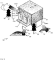
FIG. 12 depicts a visual representation of the updated time dependent previsualization projection mapping model, according to non-limiting implementations. -
FIG. 13 depicts in-situ projection mapping at the location ofFIG. 1 , as planned using the updated time dependent previsualization projection mapping model, according to non-limiting implementations. - Attention is directed to
FIG. 1 which depicts alocation 100 that includes a building 101 (located at given geographic coordinates 102) which may be evaluated for projection mapping using, for example, one ormore projectors 103. While represented inFIG. 1 as an "X", the givengeographic coordinates 102 may be defined as, for example, one or of GPS (Global Positioning System) coordinates, GLONASS (Globalnaya Navigazionnaya Sputnikovaya Sistema) coordinates, latitude/longitude pairs, and the like. While not depicted, it is further assumed that a position of thebuilding 101 at thecoordinates 102 may be further defined with respect to a heading (e.g. a direction of a facade of the building 101). Determining where to position theprojectors 103 relative to thebuilding 101 for projection mapping planning can be a complex problem, which is further complicated by landscape and/or geographic features in the area of the building, such astrees 105,hillocks 107, and the like. For example, the position of thetrees 105, and the like, generally restrict where theprojectors 103 may be positioned as thetrees 105 restrict lines of site. Similarly, thehillocks 107, and/or other changes in elevation relative to thebuilding 101, may affect the images projected by theprojectors 103 during projection mapping, as when aprojector 103 is located on ahillock 107, the angle and/or pose of anyprojectors 103 on ahillock 107 may have a different elevation fromother projectors 103. - Other environmental factors may further affect the projection mapping. For example, the Sun 109 has a path through the sky, relative to the building 101 (e.g. according to the
coordinates 102 and/or a heading) that will cause thebuilding 101 to be illuminated at different angles and different brightness levels. Indeed, in many prior art projection mapping scenarios, projection occurs only after sunset. Similarly, the Moon 111 also has a path through the sky, relative to thebuilding 101 that will cause thebuilding 101 to be illuminated at different angles and different brightness levels, after sunset, which is further dependent on the phases of the Moon 111. - Furthermore, as depicted, the
building 101 has acomplex facade 113 with a portico that includes multiple steps, a gable, columns, etc. Hence, in projection mapping, images projected onto thefacade 113 by theprojectors 103 are to be adapted for projection onto these architectural features. - Indeed, in previsualization projection mapping planning, computer models of objects, such as the
building 101, are used to determine respective locations and/or a number of theprojectors 103, estimates of how to render images to be projected, including adjusting the images for environmental light factors, and event planning (e.g. when to start the projection mapping at an event). For example, objects such as thebuilding 101 may be rendered at a display device using a computer model, and numbers and/or locations of theprojectors 103 are selected based on the computer model. - However, to accurately render such images for in-situ projection mapping, a high-resolution model of the
building 101 is obtained using laser-scanning techniques, and/or a computer aided drawing (CAD) model of thebuilding 101 may be available, for example from the original construction of thebuilding 101. Either way, such models are generally both large and require a large processing resource overhead; further, obtaining such models acts as a general impedance to planning projection mapping sites, such as determining where to place theprojectors 103. - Hence, ideally, the previsualization phase of the projection mapping planning would occur independent of obtaining such high-resolution models, at least initially.
- Complicating the problem, the
coordinates 102 and/or the heading of thebuilding 101 may not initially be known, however an address of thebuilding 101 may be known. - Hence, attention is next directed to
FIG. 2 which depicts asystem 200 that includes adevice 201 configured for automated projection mapping previsualization. As depicted, thesystem 200 includes a publicly accessibleremote mapping server 203 storing acomputer model 205 of an object onto which projection mapping is to occur (and/or is to be evaluated for projection mapping), for example thebuilding 101. The publicly accessibleremote mapping server 203 is interchangeably referred to hereafter as theserver 203. Furthermore, while present implementations will be described with respect to thebuilding 101, present implementations may be applied to any object and/or structure onto which projection mapping is to occur and/or which is to be evaluated for projection mapping. Thedevice 201 and theserver 203 are in communication usingrespective communication links 207 with acommunication network 209. - As depicted, the
system 200 further includes anoptional weather server 211 configured to provideweather data 213 to thedevice 201. For example, thedevice 201 may request theweather data 213 for a given location (e.g. at the building 101) and/or a given time period (for example, a projection mapping event that is to occur at the building 101). Theweather server 211 may comprise a publicly accessible remote weather server in communication thedevice 201 usingrespective communication links 207 with thecommunication network 209. - The
device 201 comprises acontroller 220, amemory 222, a communication interface 224 (interchangeably referred to hereafter as the interface 224), adisplay device 226 and one ormore input devices 228. Thememory 222 stores: anapplication 232;images 234 to be rendered for projection onto an object (e.g. the building 101) located at the givengeographic coordinates 102, anddata 236 for generating one or more of Sun behavior and Moon behavior at the givengeographic coordinates 102. However, in other implementations, theimages 234 and/or thedata 236 are not stored at thememory 222, are accessible to thecontroller 220 via, for example, the interface 224 (e.g. downloadable from another device and/or memory). In yet further implementations, theimages 234 can be generated upon demand, for example using an image generator (e.g. at thedevice 201 and/or another device). - The
images 234 generally comprise images that may be rendered for projection onto an object such as thebuilding 101; for example, for projection mapping, theimages 234 may be divided into portions for projection onto various surfaces of thebuilding 101. However, when the previsualization techniques, as described below, are to be used to evaluate thelocation 100 for suitability for projection mapping, theimages 234 may comprise blank and/or white and/or default images (e.g. images without content specifically designed for projection mapping onto thebuilding 101 and/or an object). - As depicted, the
memory 222 further storesoptional event data 238 defining an event that may occur proximal an object (e.g. the building 101); theevent data 238 may include, but is not limited to, times of an event that may occur proximal the building 101 (and the like), an address of the event, estimation of crowd sizes during the times of the event, and the like. In some implementations, theevent data 238 defines an event during which projection mapping onto thebuilding 101 may occur. In yet further implementations, theevent data 238 may be used to determine illumination (e.g. luminance) and/or perceived illumination (e.g. brightness) of thebuilding 101 by people at the event, for example based on estimated times and sizes of crowds at the event, and estimates of light produced by such crowds (e.g. due to glare from cell phones, and the like). Theevent data 238 may be received from another external device and/or server, and/or provisioned at thememory 222 by an administrator of thedevice 201; alternatively, theevent data 238 may be stored at another device and is accessible to thecontroller 220 via theinterface 224. - The
controller 220 is generally configured to: receive, using thecommunication interface 224, thecomputer model 205 of the object (e.g. the building 101) from the publicly accessibleremote mapping server 203, thecomputer model 205 comprising a publicly available three-dimensional computer model, thecomputer model 205 defining the object (e.g. the building 101) in geographic coordinates and elevation coordinates; generate a time dependent previsualization projection mapping model for the object (e.g. the building 101) using theimages 234, thecomputer model 205 and thedata 236 for generating one or more of the Sun behavior and the Moon behavior at the givengeographic coordinates 102; and, control thedisplay device 226 to render a previsualization of the time dependent previsualization projection mapping model. Thecontroller 220 may be further configured to determine a heading of the object (e.g. the building 101) using thecomputer model 205 in order to determine a position of theSun 109 and/or theMoon 111 with respect to thefacade 113 of thebuilding 101 at a given time. - The
server 203 generally comprises any publicly accessible remote mapping server, accessible, for example, via the Internet and including, but not limited to, a Google™ mapping server, a government mapping server (e.g. as maintained by a municipality, a region a government) and the like. Indeed, thecomputer model 205 comprises a model of thebuilding 101 in any suitable format including, but not limited to, DXF (Drawing Exchange Format) file, a GIS (geographic information system) file, a PCD (Point Cloud Data) file, an OBJ file, a color coordinate file defining color of the building 101), and the like. - Indeed, such computer models are generally publicly available via mapping servers and generally comprise relatively low fidelity geometric models of structures, buildings, and the like, as well as their absolute respective positions relative to the Earth. Such computer models are often generated by users and uploaded to such mapping servers; and/or such computer models may be generated using surveys of a region (e.g. as performed using sonar and/or stereo photography, and the like, from an airplane, a helicopter, a drone, and the like). Such computer models generally include data which define a geographic location and elevation of points in space that in turn define a structure and/or a building.
- Furthermore, such computer models of objects, and the like, are generally stored in association with other computer models of adjacent objects and/or buildings and/or structures. Indeed, such computer models may further be stored with data indicative of "busy" times at various locations, such as buildings, which may further be used to estimate light emitted by buildings at given times. Indeed, in some implementations, such other computer models may also include locations of streetlamps, and the like, as well as data indicative of times those streetlamps are operational and/or brightness of light emitted by the streetlamps, and the like. Alternatively, the
device 201 may be configured to estimate brightness and/or direction of light emitted by the streetlamps given locations of the streetlamps. - Furthermore, such computer models are generally stored in association with three-dimensional models of a geographic region adjacent the objects such as position estimates of the
trees 105 and/or topographical data, for example elevations of the region around thebuilding 101, such as elevations of thehillocks 107. - Hence, when the
device 201 requests thecomputer model 205 theserver 203, thedevice 201 can request that thecomputer model 205 include not only a model of thebuilding 101, but a geographic region adjacent thebuilding 101, which may include environmental information (e.g. positions of trees, adjacent buildings, streetlamps etc., and/or times of operation and/or "busy" periods), topographic information and the like. - However, a limitation of such computer models is that their resolution is generally too low (e.g. on the order of 1 point per meter) to perform accurate and/or precise projection mapping; however, as described herein, such computer models may be used for automated projection mapping previsualization.
- For example, attention is directed to
FIG. 3 which depicts a visual representation of the computer model 205 (interchangeably referred to hereafter as the model 205), which defines amodel 301 of thebuilding 101,models 305 of the trees 105 (e.g. environmental data), andmodels 307 of the hillocks 107 (e.g. topographical data). Furthermore, features in themodel 205 are defined by a plurality ofpoints 310; while only sevensuch points 310 are shown inFIG. 3 , each represented by a respective "X", themodel 307 comprises a plurality ofsuch points 310, each comprising respective geographic coordinates (e.g. as depicted latitude and longitude), and elevation, e.g. relative to the Earth. Hence, each of themodels building 101, thetrees 105 and thehillocks 107 relative to each other and relative to the Earth. While not depicted, themodel 205 may include positions of streetlamps, buildings and the like adjacent thebuilding 101, and may further include times of operation of the streetlamps, the buildings and the like, and/or busy periods and/or schedules of the streetlamps, buildings and the like, etc. - However, as the model 205 (e.g. the
models building 101 obtained using an in-situ laser scan of the building 101), thepoints 310 may not be sufficient to define fine details of thebuilding 101, thetrees 105, and thehillocks 107. For example, as depicted, the columns and steps of thebuilding 101 are not defined by themodel 301; rather, themodel 301 defines the general three-dimensional shape and outline of thebuilding 101, relative to the Earth. Similarly, the branches and trunks of thetrees 105 are not defined by themodel 305; rather themodel 305 defines the general three-dimensional volume of thetrees 105, as well as their position relative to the Earth and to thebuilding 101. Similarly, topographical detail (e.g. local depressions and/or bumps) of thehillocks 107 are not defined by themodel 307; rather themodel 307 defines the general three-dimensional volume of thehillocks 107, as well as their position relative to the Earth and to thebuilding 101. - Furthermore, the given
geographic coordinates 102 of thebuilding 101 may be determined from themodel 205. For example, when requesting themodel 205 from theserver 203, thedevice 201 may specify a street address, and the like, of thebuilding 101 in a request for themodel 205, and theserver 203 may return themodel 205 as corresponding to the specified street address, themodel 205 including thegeographic coordinates 102 of thebuilding 101. - Furthermore, a heading of the
building 101 may be determined from themodel 205, for example a geographical direction in which thefacade 113 of thebuilding 101 is facing. - Returning to
FIG. 2 , thedata 236 comprises data for generating one or more of Sun behavior and Moon behavior at given geographic coordinates. For example, thedata 236 may comprise formulae, a table, a lookup table, and the like, for positions of theSun 109 and/or theMoon 111 relative to the Earth, as a function of geographic location, time of day and date. Using thedata 236, a time dependent model of the behavior of theSun 109 and/or theMoon 111 at a given geographic location may be determined which, when combined with themodel 205, further yields a time dependent model of the position of light from theSun 109 and/or theMoon 111 on thebuilding 101 and/or thefacade 113, including, but not limited to, shadows from thetrees 105, and the like. - Such a time dependent model may further be combined with the
weather data 213 received from theweather server 211 and/or theevent data 238 to further determine a time dependent model of other ambient light on thebuilding 101, for example based on cloud cover that may obscure theSun 109 and/or theMoon 111, and/or based on light from crowds at an event adjacent thebuilding 101. - Similarly, any data in the
model 205, indicative of ambient light emitted by adjacent buildings and/or streetlamps at given times, may be used to further supplement a time dependent model of light on thebuilding 101. - Indeed, independent of (and/or supplemented by) the
weather data 213, theevent data 238, and the like, a time dependent model time dependent model of the position of light from theSun 109 and/or theMoon 111 on thebuilding 101 is combined with theimages 234 to generate a time dependent previsualization projection mapping model, which may be used to determine one or more of: respective positions and/or respective poses of theprojectors 103, render theimages 234 for previsualization of projection mapping by theprojectors 103 onto thebuilding 101, adjust the previsualization of theimages 234 for a positon of light and/or shadow on thebuilding 101 and the like. - For example, in a previsualization using the
model 205, respective models of theprojectors 103 may be positioned relative to themodel 301 of thebuilding 101, themodel 305 of thetrees 105 and/or themodel 307 of the hillocks 10. Furthermore, portions of theimages 234 may be extracted and assigned to each of theprojectors 103 for projection within the previsualization. The portions of theimages 234 may further be warped for viewing from a particular geographic viewing location. The positions of theprojectors 103 may be adjusted within the previsualization to determine estimates of the positions of theprojectors 103 for in-situ deployment adjacent thebuilding 101. Furthermore, the time dependent model may be used to determine how to adjust the projected images to compensate for ambient light. - The
device 201 can comprise any suitable computing device that may be used for projection mapping previsualization, including but not limited to a graphics processing unit (GPU), a graphics processing device, a graphics processing engine, a video processing device, a personal computer (PC), a laptop, a server, and the like. - The
controller 220 can comprise a processor and/or a plurality of processors, including but not limited to one or more central processors (CPUs) and/or one or more processing units; either way, thecontroller 220 comprises a hardware element and/or a hardware processor. Indeed, in some implementations, thecontroller 220 can comprise an ASIC (application-specific integrated circuit) and/or an FPGA (field-programmable gate array) specifically configured to implement specific projection mapping previsualization functionality. Hence, thedevice 201 is preferably not a generic computing device, but a device specifically configured to implement specific projection mapping previsualization functionality. For example, thedevice 201 and/or thecontroller 220 can comprise a computer executable engine configured to implement specific projection mapping previsualization functionality. - The
memory 222 can comprise a non-volatile storage unit (e.g. Erasable Electronic Programmable Read Only Memory ("EEPROM"), Flash Memory) and a volatile storage unit (e.g. random access memory ("RAM")). Programming instructions that implement the functional teachings of thedevice 201 as described herein are typically maintained, persistently, in thememory 222 and used by thecontroller 220 which makes appropriate utilization of volatile storage during the execution of such programming instructions. Those skilled in the art recognize that thememory 222 is an example of computer readable media that can store programming instructions executable on thecontroller 220. Furthermore, thememory 222 is also an example of a memory unit and/or memory module and/or a non-volatile memory. - In particular, the
memory 222 stores anapplication 232 that, when processed by thecontroller 220, enables thecontroller 220 and/or thedevice 201 to: receive, using thecommunication interface 224, thecomputer model 205 of the object (e.g. the building 101) from the publicly accessibleremote mapping server 203, thecomputer model 205 comprising a publicly available three-dimensional computer model, thecomputer model 205 defining the object (e.g. the building 101) in geographic coordinates and elevation coordinates; generate a time dependent previsualization projection mapping model for the object (e.g. the building 101) using theimages 234, thecomputer model 205 and thedata 236 for generating one or more of the Sun behavior and the Moon behavior at the givengeographic coordinates 102; and, control thedisplay device 226 to render a previsualization of the time dependent previsualization projection mapping model. Thecontroller 220 may be further configured to determine a heading of the object (e.g. the building 101) using thecomputer model 205. -
Interface 224 comprises any suitable wired or wireless communication interface configured to communicate with thecommunication network 209 in a wired and/or wireless manner as desired.Interface 224 can hence include one or more wired and/or wireless network interface cards and/or radios and the like. For example, thecommunication network 209 may include one or more of the Internet, a WLAN (wireless local area network), a WiFi network, a cellphone network, and the like, and theinterface 224 comprises any suitable interface for implementing alink 207 thereto. - The
display device 226 comprises any suitable one of, or combination of, flat panel displays (e.g. LCD (liquid crystal display), plasma displays, OLED (organic light emitting diode) displays) and the like, as well as one or more touch screens (including capacitive touchscreens and/or resistive touchscreens). In some implementations, thedisplay device 226 may include a virtual reality (VR) device. - The
input device 228 comprises any suitable one of, or combination of keyboards, pointing devices, touchpads, touchscreens, buttons, and the like. Furthermore, one or more of thedisplay device 226 and theinput device 228 may be external to thedevice 201 and accessible to thedevice 201 via theinterface 224, and the like. - In any event, it should be understood that a wide variety of configurations for the
device 201 are within the scope of present implementations. - Attention is now directed to
Fig. 4 , which depicts a flowchart of amethod 400 for projection mapping previsualization, according to non-limiting implementations. In order to assist in the explanation ofmethod 400, it will be assumed thatmethod 400 is performed using thecontroller 220 of thedevice 201, for example when thecontroller 220 processes theapplication 232. Indeed,method 400 is one way in which thedevice 201 and/or thecontroller 220 can be configured. Furthermore, the following discussion ofmethod 400 will lead to a further understanding of thedevice 201, and the system 20, and their various components. However, it is to be understood that thesystem 200 and/or thedevice 201 and/or thecontroller 220 and/or themethod 400 can be varied, and need not work exactly as discussed herein in conjunction with each other, and that such variations are within the scope of present implementations. - Regardless, it is to be emphasized, that the
method 400 need not be performed in the exact sequence as shown, unless otherwise indicated; and likewise, various blocks may be performed in parallel rather than in sequence; hence the elements of themethod 400 are referred to herein as "blocks" rather than "steps". It is also to be understood, however, that themethod 400 can be implemented on variations of thedevice 201 as well. - At a
block 402, thecontroller 220 receives, using thecommunication interface 224, acomputer model 205 of an object (e.g. the building 101) from a publicly accessibleremote mapping server 203, thecomputer model 205 comprising a publicly available three-dimensional computer model, thecomputer model 205 defining the object (e.g. the building 101) in geographic coordinates and elevation coordinates. - At a
block 404, thecontroller 220 generates a time dependent previsualization projection mapping model for the object (e.g. the building 101) using theimages 234, thecomputer model 205 and thedata 236 for generating one or more of the Sun behavior and the Moon behavior at the givengeographic coordinates 102. When theimages 234 and/or thedata 236 are not stored in thememory 222, the block 204 can include, but is not limited to, one or more of retrieving theimages 234 and/or the data from another device, and generating theimages 234. - At a
block 406, thecontroller 220 controls thedisplay device 226 to render a previsualization of the time dependent previsualization projection mapping model. - At a
block 408, thecontroller 220 aligns a second computer model of the object with thecomputer model 205 of the object, the second computer model of the object comprising a higher resolution computer model than the publicly available three-dimensional computer model. The second computer model may then be augmented using thecomputer model 205 and/or time dependent previsualization projection mapping model and used to render theimages 234 for projection mapping by theprojectors 103 onto thebuilding 101. - The
method 400 will now be described with reference toFIG. 5 to FIG. 12 . - Attention is next directed to
FIG. 5 which is substantially similar toFIG. 2 with like elements having like numbers. In particular,FIG. 5 depicts an example implementation of theblock 402 of themethod 400. Thecontroller 220 receives thecomputer model 205 by transmitting arequest 501 for thecomputer model 205 to theserver 203 via theinterface 224, and thelinks 207 between thedevice 201, theserver 203 and thenetwork 209. For example, theapplication 232 may include a network address of theserver 203, and thecontroller 220 may transmit therequest 501 to theserver 203 based on the network address. - Hence, the
request 501 may be transmitted when thecontroller 220 is implementing the application 223 as part of a previsualization projection mapping process. Therequest 501 may include an address of thebuilding 101 and/orgeographic coordinates 102 of the building, and/or a set of geographic coordinates that define a region surrounding the building 101 (e.g. including the building 101). In some implementations, the address of thebuilding 101, and the like, may be determined from theevent data 238; hence, inFIG. 5 , thecontroller 220 is depicted as having optionally retrieved theevent data 238 from thememory 222. - In addition, the
device 201 may be configured to interact with an API (application program interface) of theserver 203, and therequest 501 may hence be configured for receipt by the API of theserver 203. - The
server 203, in response to receiving therequest 501, transmits themodel 205 to thedevice 201, where themodel 205 is received by the controller 220 (e.g. at theblock 402 of the method 400). However, any other process for receiving themodel 205 at thecontroller 220 is within the scope of the present specification. - In yet further implementations, the
model 205 may be received via a browser application at thedevice 201 and themodel 205 may be retrieved by browsing theserver 203 and/or map data at theserver 203 to select a region that corresponds to themodel 205. In some of these implementations, thedata 236 may also be received via a browser application. -
FIG. 5 further depicts thecontroller 220 retrieving thedata 236 from thememory 222. - Attention is next directed to
FIG. 6 , which is substantially similar toFIG. 5 with like elements having like numbers.FIG. 6 further depicts thecontroller 220 receiving theweather data 213 from theweather server 211. Theweather data 213 may be requested by thecontroller 220, for example based on dates and/or a location in theevent data 238 and/or based on thegeographic coordinates 102 and/or based on geographic locations in themodel 205. - Attention is next directed to
FIG. 7 which is substantially similar toFIG. 6 with like elements having like numbers. In particular,FIG. 7 depicts an example implementation of theblocks method 400. In particular, inFIG. 7 , thecontroller 220 generates (e.g. at theblock 404 of the method 400) a time dependent previsualizationprojection mapping model 701 for the object using the images 234 (e.g. as retrieved from the memory 222), thecomputer model 205 and thedata 236 for generating one or more of the Sun behavior and the Moon behavior at the given geographic coordinates. As depicted, thecontroller 220 optionally generates the time dependent previsualizationprojection mapping model 701 further using theweather data 213 and theevent data 238. - As also depicted in
FIG. 7 , thecontroller 220 further controls (e.g. at theblock 406 of the method 400) thedisplay device 226 to render a previsualization of the time dependent previsualizationprojection mapping model 701. In some implementations, the previsualization of the time dependent previsualizationprojection mapping model 701 is rendered in a browsing application at thedevice 201. - Attention is next directed to
FIG. 8 which depicts an example visual representation of the previsualization of the time dependent previsualizationprojection mapping model 701 as rendered at thedisplay device 226. While the rendering of previsualization of the time dependent previsualizationprojection mapping model 701 is depicted from a particular perspective, in some implementations, the previsualization of the time dependent previsualizationprojection mapping model 701 may be rendered from different angles and/or in a virtual reality display device. - In
FIG. 8 , themodels display device 226 using themodel 205, as well as example locations of theprojectors 103, as indicated usingmodels 803 of theprojectors 103. - The locations of the
models 803 of theprojectors 103 may be set manually and/or automatically. For example, assuming that a given portion of theimages 234 are to be projection mapped onto thefacade 113 of thebuilding 101 and/or given surfaces of thebuilding 101, thecontroller 220 may automatically determine estimates of the positons of theprojectors 103 relative to themodels - Hence, in some implementations, the time dependent previsualization
projection mapping model 701 includes an indication of where to geographically locate one ormore projectors 103, relative to an object (e.g. the building 101), the one ormore projectors 103 for projecting the images 234 (and/or portions thereof) onto the object. - Indeed, the
models 803 of theprojectors 103 may generally include both intrinsic and extrinsic parameters of theprojectors 103 including, but not limited to, positions within the time dependent previsualization projection mapping model 701 (e.g. relative to themodel 301 of the building 101), angles of theprojectors 103 within the time dependent previsualization projection mapping model 701 (e.g. relative to themodel 301 of the building 101), including, but not limited to pose data, lens characteristics and the like. The position and/or pose of themodels 803 of theprojectors 103 is determined from the estimates of the positons of theprojectors 103 relative to themodels - Furthermore, the
models 803 of theprojectors 103 are further located such that thetrees 105 and/or thehillocks 107, and the like (e.g. as represented by themodels 305, 307) do not interfere with and/or block their projection and/or their placement. For example, amodel 803 of aprojector 103 is not located behind a model 305 (e.g. relative to the model 301), nor at a position of amodel 305. Indeed, eachmodel 803 may further include physical dimensions of arespective projector 103, and themodels 803 are further positioned within the time dependent previsualizationprojection mapping model 701 at locations that would be achievable at theactual location 100 including, but not limited to, on thehillocks 107 and/or using scaffolding and the like. - As also depicted in
FIG. 8 , thecontroller 220 may further determine a heading 899 of thebuilding 101, for example to align themodel 205 with paths of theSun 109 and theMoon 111. - For example, as also depicted in
FIG. 8 , respective timedependent paths Sun 109 and theMoon 111, relative to themodels building 101 etc.) and/or the heading 899, are rendered at the display device using thedata 236. While the entirety of thepaths Sun 109 and theMoon 111 along theirrespective paths projection mapping model 701 using aninput device 228 and/or a graphic user interface, for example aslider 812, to set a date and time for the time dependent previsualizationprojection mapping model 701. - At the time depicted, however, the
Moon 111 is positioned relative to one of thetrees 105, as represented by themodels 305, such that light 813 from theMoon 111 causes one of thetrees 105 to cast ashadow 814 onto the facade of the building 101 (again, as represented by the model 301). Theshadow 814 depicted inFIG. 8 is an estimate of a shape of a shadow cast by anactual tree 105, as themodels 305 of thetrees 105 are not exact and/or low-resolution. - Furthermore, as depicted, an
indication 815 of an estimated crowd (e.g. at a given time as selected, for example, by the slider 812) is rendered at thedisplay device 226 using theevent data 238, which may include anestimate 816 of ambient light emitted by the estimated crowd, theestimate 816 also being time dependent (and hence also adjustable using, for example, the slider 812). - As also depicted in
FIG. 8 , a timedependent estimate 818 of cloud cover (e.g. at a given time as selected, for example, by the slider 812) has been rendered at thedisplay device 226 using theweather data 213. - While not depicted, the time dependent previsualization
projection mapping model 701 may further include time dependent estimates of ambient light from adjacent buildings and/or streetlamps as described above. - As further depicted in
FIG. 8 ,respective models 803 of theprojectors 103 have been positioned to projection map portions 834-1, 834-2, 834-3 of theimages 234 onto thebuilding 101, as represented by the model 301 (the portions 834-1, 834-2, 834-3 interchangeably referred to hereafter, collectively, as the portions 834 and, generically, as a portion 834). While only three portions 834 are depicted, the number of portions 834 corresponds to the number ofprojectors 103 and/or the number ofprojector models 803. - The portions 834 are depicted intermediate a
respective projector model 803 and themodel 301 of thebuilding 101, though it is understood that the portions 834 are (e.g. virtually) projected onto themodel 301 within the time dependent previsualizationprojection mapping model 701. - For example, the portions 834-1, 834-2 are to be projected onto the
facade 113 of thebuilding 101, and the portion 834-3 is to be projected onto a side of thebuilding 101. In other words, the portions 834 are determined using the three-dimensional geometry of thebuilding 101 as represented in themodel 301 and/or themodel 205. - In particular, the portion 834-1 is to be projected onto the
facade 113 of thebuilding 101 that includes theshadow 814, and hence the portion 834-1 includes anarea 844 that has a brightness that has been adjusted to compensate for theshadow 814 and/or the brightness remaining areas of the portion 834-1 are adjusted to compensate for theshadow 814. In other words, the region of thebuilding 101 around theshadow 814 will be illuminated by the light 813 from theMoon 111, and hence thearea 844 of the portion 834-1 compensates for the difference in brightness of the illumination of thebuilding 101 by theMoon 111. - Indeed, a position and/or shape of the
area 844 is further time dependent as based on thedata 236. - Indeed, any time dependent ambient light factors as determined from the
model 205, thedata 236, theevent data 238, and theweather data 213 may be used to adjust the portions 834-1, 834-2, 834-3 of theimages 234. In other words, the portions 834 are time dependent according to the determined time-dependent ambient lighting conditions. - Hence, the positions of the
models models 803 and theimages 234, are initially used to determine locations of theprojectors 103 at thelocation 100 in order to projection map theimages 234, and then the portions 834 of theimages 234 are adjusted for ambient light based on one or more of themodel 205, thedata 236, theevent data 238, and theweather data 213. - Also depicted in
FIG. 8 is ageographic viewing location 850 which can comprise a location from which the projection mapping is to be viewed at the event. In some implementations, thegeographic viewing location 850 can be preconfigured, for example in theevent data 238, as there may be a limited area adjacent thebuilding 101 where an associated event may be held. In these implementations, thecontroller 220 further generates the time dependent previsualizationprojection mapping model 701 for the object further using thegeographic viewing location 850, for example to determine positions of theprojectors 103 and/or warping of the portions 834 such that the projection mappedimages 234 appear according to a given perspective and/or aspect ratio from thegeographic viewing location 850. - Alternatively, the
controller 220 may be further configured to determine, from the time dependent previsualizationprojection mapping model 701, a best geographic viewing location for viewing projection mapping of the images onto the object. For example, themodel 205 may indicate that areas adjacent thebuilding 101 that are better for viewing the projection mapping and/or for managing crowds: for example, areas where thetrees 105 are located, as indicated by themodels 305 and/or areas where thehillocks 107 are located, as indicated by themodels 307, would not be selected as a best geographic viewing location. However, an area adjacent thebuilding 101, having sightlines to thefacade 113 may be selected as a best geographic viewing location. - Hence, the
geographic viewing location 850 may be predetermined, or selected as a best geographic viewing location by thecontroller 220. - Indeed, the
geographic viewing location 850, whether predetermined or selected by thecontroller 220, may be used to plan crowd control at an associated event, for example to direct crowds towards an area around thegeographic viewing location 850 using fencing, and the like. - In any event, in this manner, the time dependent previsualization
projection mapping model 701 may be used to render a time-dependent previsualization of projection mapping onto thebuilding 101 prior to any site visit to thebuilding 101. - Furthermore, using the time dependent previsualization
projection mapping model 701 the suitability of thelocation 100 for projection mapping may be determined as well as a cost estimate for implementing the projection mapping. For example, using the time dependent previsualizationprojection mapping model 701 it may be determined that the number of hours of sun at thelocation 100 makes a projection mapping based event unlikely to be popular (e.g. as the projection mapping may be washed out by the Sun until late into the evening in summer at high latitudes). Similarly, from the time dependent previsualizationprojection mapping model 701, it may be determined that the shadows on thebuilding 101 would degrade the projection mapping and/or would require a large number of projectors than a budget allows. Indeed, themodel 205 and/or associated data may also be used to determine whether thelocation 100 is popular with people who would likely attend a projection mapping based event; for example, thedevice 201 may determine whether thelocation 100 is popular or not based on a number of photos of thelocation 100 posted in social media sites and/or at theserver 203. - Hence, the time dependent previsualization
projection mapping model 701 may be used to evaluate thelocation 100 for projection mapping prior to any site visit, which can be expensive. - Furthermore, the
application 232, themethod 400 and/or the time dependent previsualizationprojection mapping model 701 may be implemented as a stand-alone application and/or as a plug-in to a browser application. - For example, a browser may be used to browse to an object and/or building and/or structure of interest using a map server, such as Google™ maps, and the like, and images may be accessed and/or generated for projection onto the object and/or building and/or structure of interest within the plug-in. Drag and drop operations, and the like, may be used to select the projector locations, and the plug-in can implement the
method 400 to show the time dependent previsualizationprojection mapping model 701 within the plug-in at the browser application. - However, once the time dependent previsualization
projection mapping model 701 has been generated, and/or used to estimate projector location and the like, a site visit can occur to generate a second computer model of the object (e.g. the building 101) comprising a higher resolution computer model than the publicly available three-dimensional computer model 205. Such higher resolution computer model is then used to more precisely generate portions of theimages 234 for projection mapping. For example, themodel 205 does not include detail of the facade 113 (such as the steps and the columns), so the second higher resolution computer model is used to determine locations of the detail of thefacade 113 to implement in-situ projection mapping. - For example, attention is next directed to
FIG. 9 , which is substantially similar toFIG. 1 , with like elements having like numbers. However, inFIG. 9 , asurveyor 901 is using a laser scanning device 903 (e.g. a LIDAR (Light Detection and Ranging) device, and the like) to scan the surfaces of the building 101 (e.g. as depicted, the facade 113) to generate amodel 905 of thebuilding 101 that is of a higher resolution than themodel 205. However, such amodel 905 may also be obtained and/or generated from blueprints of thebuilding 101, CAD drawings of thebuilding 101, and the like. - Attention is next directed to
FIG. 10 , which is substantially similar toFIG. 2 , with like elements having like numbers. However,FIG. 10 depicts an example implementation of theblock 408 of themethod 400. It is assumed inFIG. 10 that the time dependent previsualizationprojection mapping model 701 has been generated and that the time dependent previsualizationprojection mapping model 701 includes themodel 205, as depicted inFIG. 8 . It is further assumed inFIG. 10 that themodel 905 has been received at the controller 220 (e.g. for example as uploaded to thedevice 201 by thesurveyor 901 using an associated communication device, not depicted). - As depicted in
FIG. 10 , thecontroller 220 is aligning thesecond model 905 of thebuilding 101 with themodel 205 of thebuilding 101 to generate an updated time dependent previsualizationprojection mapping model 1001 that includes themodel 905; however, portions of themodel 205 that correspond to themodel 905 are replaced by the model 905 (e.g. the model 301). - For example, attention is directed to
FIG. 11 , which is substantially similar toFIG. 8 , with like elements having like numbers, however inFIG. 11 the time dependent previsualizationprojection mapping model 701 is not being rendered at thedisplay device 226; rather, thecontroller 220 is aligning thesecond computer model 905 of thebuilding 101 with thecomputer model 205 of the object (and specifically themodel 301 of the building 101) within the time dependent previsualizationprojection mapping model 701. InFIG. 11 thepaths Sun 109 andMoon 111 are not depicted, but are nonetheless assumed to be present. - As depicted, the
second computer model 905 comprises a higher resolution computer model than the publicly available three-dimensional computer model 205 and hence detail of thebuilding 101 is included in thesecond computer model 905, such as the steps and columns of thefacade 113. - As also indicated in
FIG. 11 , thecontroller 220 is aligning thesecond computer model 905 of thebuilding 101 with thecomputer model 205 using, for example an iterative closest point (ICP) process, and the like, to align corners and/or edges and/or surfaces and/or features of themodel 905 with corresponding corners and/or edges and/or surfaces and/or features of themodel 205, as represented by thearrow 1004. - The resulting updated time dependent previsualization
projection mapping model 1001 is depicted inFIG. 12 in which themodel 905 replaces themodel 301. Hence, the updated time dependent previsualizationprojection mapping model 1001 may be used to generate portions of theimages 234 to be projected by theprojectors 103 to account for the detail of thebuilding 101 represented in themodel 905. - Put another way, the
controller 220 may be further configured to generate an updated time dependent previsualizationprojection mapping model 1001 for controlling one ormore projectors 103 to project theimages 234 onto an object (e.g. the building 101) using: thesecond computer model 905; alignment of thesecond computer model 905 of the object with the computer model of 205 the object; and the time dependent previsualizationprojection mapping model 701. - Put yet another way, the
controller 220 may be further configured to augment thesecond computer model 905 of the object with geographic data from thecomputer model 205 of the object. For example, the updated time dependent previsualizationprojection mapping model 1001 includes geographic data such as positions and/or elevations of thetrees 105 and thehillocks 107, as represented by themodels model 205. Furthermore, themodel 905 is aligned with the heading 899. - In any event, the updated time dependent previsualization
projection mapping model 1001 may be used to confirm and/or re-determine the locations of theprojectors 103 and further produce portions of theimages 234 specifically for projection mapping onto the details of thebuilding 101. - For example, attention is directed to
FIG. 13 which depicts in-situ deployment of theprojectors 103 at the location 100 (FIG. 13 being substantially similar toFIG. 1 , with like elements having like numbers), at locations corresponding to the locations of themodels 803 as depicted inFIG. 8 . Furthermore, scaffolding 1301 and the like may be used to located one or more of theprojectors 103. Furthermore, the updated time dependent previsualizationprojection mapping model 1001 has been used to determine portions 1334-1, 1334-2, 1334-3 of theimages 234 that are projection mapped onto thebuilding 101 by theprojectors 103, (the portions 1334-1, 1334-2, 1334-3 interchangeably referred to hereafter, collectively, as the portions 1334 and, generically, as a portion 1334). Each of the portions 1334-1, 1334-2, 1334-3 correspond to the portions 834-1, 834-2, 834-3 and hence the portion 1334-1 includes anarea 1344 corresponding to thearea 844 to compensate for a tree shadow (not depicted) similar to theshadow 814. Furthermore, like the portions 834, the portions 1334 are time dependent according to the determined time-dependent ambient lighting conditions. - Furthermore, the portions 1334 may be stored at each of the projectors 103 (e.g. the portions 1334 are loaded and/or uploaded to the projectors 103) and/or the portions 1334 are transmitted to the
projectors 103 by a device (not depicted) controlling theprojectors 103 and with which theprojectors 103 are in communication. - Disclosed herein is an apparatus and method for automated projection mapping previsualization in which online repositories of 3D building models and/or object information (e.g. Google™ Maps and the like) are accessed to retrieve low-resolution and/or publicly available models of building and/or objects. The latitude/longitude of a location can be determined from such models and used to determine the natural ambient light conditions due to the Sun and the Moon and/or event to determine a time of year that may be better for projection mapping: for example, in regions close to the Arctic Circle, projection mapping may difficult in the summer months. Furthermore, weather in the area can be determined to adjust the projection mapping, or alternatively to, determine how many hours (e.g. on average) projection mapping may be effective (e.g. according to how much sunny days are in a given time period, on average). Furthermore, the three-dimensional building models can be downloaded and used to help determine projector placement, as well as generate estimates of images to be projected using the three-dimensional geometry of the building. Indeed, such online information may be further used to select sites and locations for consideration for projection mapping (e.g. at locations where people take a lot of photos and the like); hence social media may be incorporated into determining projection mapping locations.
- Hence, using the disclosed apparatus and method may enable browsing of a map server, such as Google™ Maps, selection of a location for evaluation for projection mapping, and an automatic estimate of projector placement to render a previsualization of projection mapping at the location. The previsualization is viewable at a display device, that may include a virtual reality device, and further may enable an evaluation of the suitability of the location for projection mapping and/or the cost.
- Furthermore, the disclosed method may be implemented as a stand-alone application and alternatively implemented as a plug-in to a browser application, for example, to access a map server to download an object model and, using the plug-in, perform a projection mapping previsualization within the browser application.
- Those skilled in the art will appreciate that in some implementations, the functionality of the
device 201 can be implemented using pre-programmed hardware or firmware elements (e.g., application specific integrated circuits (ASICs), electrically erasable programmable read-only memories (EEPROMs), etc.), or other related components. In other implementations, the functionality of thedevice 201 can be achieved using a computing apparatus that has access to a code memory (not shown) which stores computer-readable program code for operation of the computing apparatus. The computer-readable program code could be stored on a computer readable storage medium which is fixed, tangible and readable directly by these components, (e.g., removable diskette, CD-ROM, ROM, fixed disk, USB drive). Furthermore, it is appreciated that the computer-readable program can be stored as a computer program product comprising a computer usable medium. Further, a persistent storage device can comprise the computer readable program code. It is yet further appreciated that the computer-readable program code and/or computer usable medium can comprise a non-transitory computer-readable program code and/or non-transitory computer usable medium. Alternatively, the computer-readable program code could be stored remotely but transmittable to these components via a modem or other interface device connected to a network (including, without limitation, the Internet) over a transmission medium. The transmission medium can be either a non-mobile medium (e.g., optical and/or digital and/or analog communications lines) or a mobile medium (e.g., microwave, infrared, free-space optical or other transmission schemes) or a combination thereof. - Persons skilled in the art will appreciate that there are yet more alternative implementations and modifications possible, and that the above examples are only illustrations of one or more implementations. The scope, therefore, is only to be limited by the claims appended hereto.
Claims (15)
- A device comprising:
a communication interface, and a controller configured to:receive, using the communication interface, a computer model of an object from a publicly accessible remote mapping server, the computer model comprising a publicly available three-dimensional computer model, the computer model defining the object in geographic coordinates and elevation coordinates, the object located at given geographic coordinates;generate a time dependent previsualization projection mapping model for the object using: images to be projected onto the object, the computer model and data for generating one or more of Sun behavior and Moon behavior at the given geographic coordinates; and,control a display device to render a previsualization of the time dependent previsualization projection mapping model. - The device of claim 1, wherein the controller is further configured to receive, from a weather server, weather data for the given geographic coordinates, and generate the time dependent previsualization projection mapping model for the object further using the weather data.
- The device of claim 1, wherein the computer model of the object further includes a three-dimensional model of a geographic region adjacent the object, and the controller is further configured to generate the time dependent previsualization projection mapping model for the object further using the three-dimensional model of the geographic region adjacent the object.
- The device of claim 1, wherein the controller is further configured to generate the time dependent previsualization projection mapping model for the object further using event data defining an event that is to occur proximal the object.
- The device of claim 1, wherein the controller is further configured to generate the time dependent previsualization projection mapping model for the object further using a geographic viewing location.
- The device of claim 1, wherein the controller is further configured to align a second computer model of the object with the computer model of the object, the second computer model of the object comprising a higher resolution computer model than the publicly available three-dimensional computer model.
- The device of claim 6, wherein the controller is further configured to generate an updated time dependent previsualization projection mapping model for controlling one or more projectors to project the images onto the object using: the second computer model; alignment of the second computer model of the object with the computer model of the object; and the time dependent previsualization projection mapping model.
- The device of claim 1, wherein the time dependent previsualization projection mapping model for the object includes an indication of where to geographically locate one or more projectors, relative to the object, the one or more projectors for projecting the images onto the object.
- A method comprising:receiving, at a controller, using a communication interface, a computer model of an object from a publicly accessible remote mapping server, the computer model comprising a publicly available three-dimensional computer model, the computer model defining the object in geographic coordinates and elevation coordinates, the object located at given geographic coordinates;generating, using the controller, a time dependent previsualization projection mapping model for the object using images to be projected onto the object, the computer model, and data for generating one or more of Sun behavior and the Moon behavior at the given geographic coordinates; and,controlling, using the controller, a display device to render a previsualization of the time dependent previsualization projection mapping model.
- The method of claim 9, further comprising: receiving, at the controller, from a weather server, weather data for the given geographic coordinates; and generating, using the controller, the time dependent previsualization projection mapping model for the object further using the weather data.
- The method of claim 9, wherein the computer model of the object further includes a three-dimensional model of a geographic region adjacent the object, and the method further comprises generating, using the controller, the time dependent previsualization projection mapping model for the object further using the three-dimensional model of the geographic region adjacent the object.
- The method of claim 9, further comprising: generating, using the controller, the time dependent previsualization projection mapping model for the object further using event data defining an event that is to occur proximal the object.
- The method of claim 9, further comprising: generating, using the controller, the time dependent previsualization projection mapping model for the object further using a geographic viewing location.
- The method of claim 9, further comprising: aligning, using the controller, a second computer model of the object with the computer model of the object, the second computer model of the object comprising a higher resolution computer model than the publicly available three-dimensional computer model.
- The method of claim 14, further comprising: generating, using the controller, an updated time dependent previsualization projection mapping model for controlling one or more projectors to project the images onto the object using: the second computer model; alignment of the second computer model of the object with the computer model of the object; and the time dependent previsualization projection mapping model.
Applications Claiming Priority (1)
| Application Number | Priority Date | Filing Date | Title |
|---|---|---|---|
| US15/671,280 US10360723B2 (en) | 2017-08-08 | 2017-08-08 | Method and apparatus for automated projection mapping previsualization |
Publications (2)
| Publication Number | Publication Date |
|---|---|
| EP3442223A2 true EP3442223A2 (en) | 2019-02-13 |
| EP3442223A3 EP3442223A3 (en) | 2019-03-06 |
Family
ID=63407023
Family Applications (1)
| Application Number | Title | Priority Date | Filing Date |
|---|---|---|---|
| EP18187346.4A Withdrawn EP3442223A3 (en) | 2017-08-08 | 2018-08-03 | Method and apparatus for automated projection mapping previsualization |
Country Status (3)
| Country | Link |
|---|---|
| US (1) | US10360723B2 (en) |
| EP (1) | EP3442223A3 (en) |
| CN (1) | CN109388359B (en) |
Families Citing this family (4)
| Publication number | Priority date | Publication date | Assignee | Title |
|---|---|---|---|---|
| US10664962B1 (en) * | 2017-12-13 | 2020-05-26 | Amazon Technologies, Inc. | Determining direction of illumination |
| US10699152B1 (en) | 2017-12-13 | 2020-06-30 | Amazon Technologies, Inc. | Image data illumination detection |
| CN111476711A (en) * | 2020-06-28 | 2020-07-31 | 航天宏图信息技术股份有限公司 | Data projection and angle correction method and device |
| US11605320B1 (en) * | 2021-10-19 | 2023-03-14 | Disney Enterprises, Inc. | Relative surface travelling map projection process |
Family Cites Families (11)
| Publication number | Priority date | Publication date | Assignee | Title |
|---|---|---|---|---|
| US20080033641A1 (en) * | 2006-07-25 | 2008-02-07 | Medalia Michael J | Method of generating a three-dimensional interactive tour of a geographic location |
| US20090219199A1 (en) | 2008-02-29 | 2009-09-03 | Caterpillar Inc. | Positioning system for projecting a site model |
| US8436872B2 (en) | 2010-02-03 | 2013-05-07 | Oculus Info Inc. | System and method for creating and displaying map projections related to real-time images |
| US8466915B1 (en) * | 2010-06-15 | 2013-06-18 | Google Inc. | Fusion of ground-based facade models with 3D building models |
| CN103455299B (en) * | 2013-09-22 | 2016-11-23 | 上海幻维数码创意科技有限公司 | The method of Large-wall stereographic projection |
| CN103533318A (en) * | 2013-10-21 | 2014-01-22 | 北京理工大学 | Building outer surface projection method |
| US20170277389A1 (en) * | 2014-08-20 | 2017-09-28 | Bkool, S.L. | Process of generation of a three-dimensional graphical representation of a geographical environment from positioning data |
| US9451245B1 (en) | 2015-01-06 | 2016-09-20 | Ryan Franklin Darling | Three dimensional digitizing and projector system |
| US10630958B2 (en) * | 2016-07-01 | 2020-04-21 | Intel Corporation | Technologies for automated projector placement for projected computing interactions |
| JP2018036479A (en) * | 2016-08-31 | 2018-03-08 | 株式会社リコー | Image projection system, information processing apparatus, image projection method, and program |
| US10802665B2 (en) * | 2016-10-05 | 2020-10-13 | Motorola Solutions, Inc. | System and method for projecting graphical objects |
-
2017
- 2017-08-08 US US15/671,280 patent/US10360723B2/en active Active
-
2018
- 2018-08-03 EP EP18187346.4A patent/EP3442223A3/en not_active Withdrawn
- 2018-08-08 CN CN201810895156.9A patent/CN109388359B/en active Active
Non-Patent Citations (1)
| Title |
|---|
| None |
Also Published As
| Publication number | Publication date |
|---|---|
| US10360723B2 (en) | 2019-07-23 |
| CN109388359A (en) | 2019-02-26 |
| EP3442223A3 (en) | 2019-03-06 |
| CN109388359B (en) | 2021-04-06 |
| US20190051041A1 (en) | 2019-02-14 |
Similar Documents
| Publication | Publication Date | Title |
|---|---|---|
| CN109388359B (en) | Method and apparatus for automatic projection mapping pre-visualization | |
| US11829592B2 (en) | Integrating maps and street views | |
| US9542770B1 (en) | Automatic method for photo texturing geolocated 3D models from geolocated imagery | |
| US10657714B2 (en) | Method and system for displaying and navigating an optimal multi-dimensional building model | |
| JP5118787B1 (en) | Orthorectification of oblique images joined to the direct view and their applications | |
| US8749580B1 (en) | System and method of texturing a 3D model from video | |
| US10048077B2 (en) | Method and system of generating an indoor floor plan | |
| US11704866B2 (en) | Systems and methods for visualization of building structures | |
| CN108474666A (en) | System and method for positioning user in map denotation | |
| US10497177B1 (en) | Tool for onsite augmentation of reality meshes | |
| US8466915B1 (en) | Fusion of ground-based facade models with 3D building models | |
| US8869058B1 (en) | Interface elements for specifying pose information for photographs in an online map system | |
| RU2601165C2 (en) | Method for automated creation of three-dimensional systems of urban panoramas based on laser scanning data | |
| KR20080029407A (en) | Method and system for providing 3d virtual contents using gis | |
| EP4196912A1 (en) | Condition-aware generation of panoramic imagery | |
| KR20140049232A (en) | Map handling method and system for 3d object extraction and rendering using image maps | |
| Ginzburg et al. | Use of a progressive web application for working with Earth remote sensing, topographic and cadastral data layers | |
| WO2023200569A1 (en) | Methods and systems for providing a real-time viewshed visualization | |
| Fisher et al. | Under Construction—Interactive Project Presentation of a Horticultural Exhibition | |
| JP2012234017A (en) | Image processing device, map display device, image processing method, and program |
Legal Events
| Date | Code | Title | Description |
|---|---|---|---|
| PUAI | Public reference made under article 153(3) epc to a published international application that has entered the european phase |
Free format text: ORIGINAL CODE: 0009012 |
|
| PUAL | Search report despatched |
Free format text: ORIGINAL CODE: 0009013 |
|
| AK | Designated contracting states |
Kind code of ref document: A2 Designated state(s): AL AT BE BG CH CY CZ DE DK EE ES FI FR GB GR HR HU IE IS IT LI LT LU LV MC MK MT NL NO PL PT RO RS SE SI SK SM TR |
|
| AX | Request for extension of the european patent |
Extension state: BA ME |
|
| AK | Designated contracting states |
Kind code of ref document: A3 Designated state(s): AL AT BE BG CH CY CZ DE DK EE ES FI FR GB GR HR HU IE IS IT LI LT LU LV MC MK MT NL NO PL PT RO RS SE SI SK SM TR |
|
| AX | Request for extension of the european patent |
Extension state: BA ME |
|
| RIC1 | Information provided on ipc code assigned before grant |
Ipc: H04N 9/31 20060101AFI20190125BHEP |
|
| STAA | Information on the status of an ep patent application or granted ep patent |
Free format text: STATUS: THE APPLICATION IS DEEMED TO BE WITHDRAWN |
|
| 18D | Application deemed to be withdrawn |
Effective date: 20190907 |