EP3442110A1 - Actuator, and tactile sensation presentation device - Google Patents
Actuator, and tactile sensation presentation device Download PDFInfo
- Publication number
- EP3442110A1 EP3442110A1 EP17769989.9A EP17769989A EP3442110A1 EP 3442110 A1 EP3442110 A1 EP 3442110A1 EP 17769989 A EP17769989 A EP 17769989A EP 3442110 A1 EP3442110 A1 EP 3442110A1
- Authority
- EP
- European Patent Office
- Prior art keywords
- vibration
- vibration plate
- actuator
- support
- piezoelectric element
- Prior art date
- Legal status (The legal status is an assumption and is not a legal conclusion. Google has not performed a legal analysis and makes no representation as to the accuracy of the status listed.)
- Granted
Links
- 230000035807 sensation Effects 0.000 title claims description 30
- 230000008602 contraction Effects 0.000 claims abstract description 17
- 238000005452 bending Methods 0.000 claims abstract description 11
- 238000006073 displacement reaction Methods 0.000 description 38
- 239000000463 material Substances 0.000 description 18
- 239000002184 metal Substances 0.000 description 15
- 229920005989 resin Polymers 0.000 description 10
- 239000011347 resin Substances 0.000 description 10
- 230000008859 change Effects 0.000 description 8
- 238000000034 method Methods 0.000 description 6
- 230000004044 response Effects 0.000 description 6
- 230000000052 comparative effect Effects 0.000 description 5
- 230000001154 acute effect Effects 0.000 description 4
- 238000000465 moulding Methods 0.000 description 4
- 239000000919 ceramic Substances 0.000 description 2
- 238000006243 chemical reaction Methods 0.000 description 2
- 239000002131 composite material Substances 0.000 description 2
- 238000012986 modification Methods 0.000 description 2
- 230000004048 modification Effects 0.000 description 2
- 230000001133 acceleration Effects 0.000 description 1
- NIXOWILDQLNWCW-UHFFFAOYSA-N acrylic acid group Chemical group C(C=C)(=O)O NIXOWILDQLNWCW-UHFFFAOYSA-N 0.000 description 1
- 239000000853 adhesive Substances 0.000 description 1
- 230000001070 adhesive effect Effects 0.000 description 1
- 230000008901 benefit Effects 0.000 description 1
- 238000010586 diagram Methods 0.000 description 1
- 239000013013 elastic material Substances 0.000 description 1
- 230000006870 function Effects 0.000 description 1
- 239000011521 glass Substances 0.000 description 1
- 238000003780 insertion Methods 0.000 description 1
- 230000037431 insertion Effects 0.000 description 1
- 239000004033 plastic Substances 0.000 description 1
- 229920003217 poly(methylsilsesquioxane) Polymers 0.000 description 1
- 230000009467 reduction Effects 0.000 description 1
- 238000010008 shearing Methods 0.000 description 1
- 229920003002 synthetic resin Polymers 0.000 description 1
- 239000000057 synthetic resin Substances 0.000 description 1
- 238000003466 welding Methods 0.000 description 1
Images


Classifications
-
- H—ELECTRICITY
- H10—SEMICONDUCTOR DEVICES; ELECTRIC SOLID-STATE DEVICES NOT OTHERWISE PROVIDED FOR
- H10N—ELECTRIC SOLID-STATE DEVICES NOT OTHERWISE PROVIDED FOR
- H10N30/00—Piezoelectric or electrostrictive devices
- H10N30/20—Piezoelectric or electrostrictive devices with electrical input and mechanical output, e.g. functioning as actuators or vibrators
- H10N30/202—Piezoelectric or electrostrictive devices with electrical input and mechanical output, e.g. functioning as actuators or vibrators using longitudinal or thickness displacement combined with bending, shear or torsion displacement
-
- B—PERFORMING OPERATIONS; TRANSPORTING
- B06—GENERATING OR TRANSMITTING MECHANICAL VIBRATIONS IN GENERAL
- B06B—METHODS OR APPARATUS FOR GENERATING OR TRANSMITTING MECHANICAL VIBRATIONS OF INFRASONIC, SONIC, OR ULTRASONIC FREQUENCY, e.g. FOR PERFORMING MECHANICAL WORK IN GENERAL
- B06B1/00—Methods or apparatus for generating mechanical vibrations of infrasonic, sonic, or ultrasonic frequency
- B06B1/02—Methods or apparatus for generating mechanical vibrations of infrasonic, sonic, or ultrasonic frequency making use of electrical energy
- B06B1/04—Methods or apparatus for generating mechanical vibrations of infrasonic, sonic, or ultrasonic frequency making use of electrical energy operating with electromagnetism
-
- G—PHYSICS
- G06—COMPUTING; CALCULATING OR COUNTING
- G06F—ELECTRIC DIGITAL DATA PROCESSING
- G06F3/00—Input arrangements for transferring data to be processed into a form capable of being handled by the computer; Output arrangements for transferring data from processing unit to output unit, e.g. interface arrangements
- G06F3/01—Input arrangements or combined input and output arrangements for interaction between user and computer
- G06F3/016—Input arrangements with force or tactile feedback as computer generated output to the user
-
- G—PHYSICS
- G06—COMPUTING; CALCULATING OR COUNTING
- G06F—ELECTRIC DIGITAL DATA PROCESSING
- G06F3/00—Input arrangements for transferring data to be processed into a form capable of being handled by the computer; Output arrangements for transferring data from processing unit to output unit, e.g. interface arrangements
- G06F3/01—Input arrangements or combined input and output arrangements for interaction between user and computer
- G06F3/03—Arrangements for converting the position or the displacement of a member into a coded form
- G06F3/041—Digitisers, e.g. for touch screens or touch pads, characterised by the transducing means
-
- H—ELECTRICITY
- H02—GENERATION; CONVERSION OR DISTRIBUTION OF ELECTRIC POWER
- H02N—ELECTRIC MACHINES NOT OTHERWISE PROVIDED FOR
- H02N2/00—Electric machines in general using piezoelectric effect, electrostriction or magnetostriction
- H02N2/0005—Electric machines in general using piezoelectric effect, electrostriction or magnetostriction producing non-specific motion; Details common to machines covered by H02N2/02 - H02N2/16
- H02N2/005—Mechanical details, e.g. housings
- H02N2/0055—Supports for driving or driven bodies; Means for pressing driving body against driven body
-
- H—ELECTRICITY
- H02—GENERATION; CONVERSION OR DISTRIBUTION OF ELECTRIC POWER
- H02N—ELECTRIC MACHINES NOT OTHERWISE PROVIDED FOR
- H02N2/00—Electric machines in general using piezoelectric effect, electrostriction or magnetostriction
- H02N2/02—Electric machines in general using piezoelectric effect, electrostriction or magnetostriction producing linear motion, e.g. actuators; Linear positioners ; Linear motors
- H02N2/04—Constructional details
-
- H—ELECTRICITY
- H02—GENERATION; CONVERSION OR DISTRIBUTION OF ELECTRIC POWER
- H02N—ELECTRIC MACHINES NOT OTHERWISE PROVIDED FOR
- H02N2/00—Electric machines in general using piezoelectric effect, electrostriction or magnetostriction
- H02N2/02—Electric machines in general using piezoelectric effect, electrostriction or magnetostriction producing linear motion, e.g. actuators; Linear positioners ; Linear motors
- H02N2/06—Drive circuits; Control arrangements or methods
-
- H—ELECTRICITY
- H10—SEMICONDUCTOR DEVICES; ELECTRIC SOLID-STATE DEVICES NOT OTHERWISE PROVIDED FOR
- H10N—ELECTRIC SOLID-STATE DEVICES NOT OTHERWISE PROVIDED FOR
- H10N30/00—Piezoelectric or electrostrictive devices
- H10N30/20—Piezoelectric or electrostrictive devices with electrical input and mechanical output, e.g. functioning as actuators or vibrators
- H10N30/204—Piezoelectric or electrostrictive devices with electrical input and mechanical output, e.g. functioning as actuators or vibrators using bending displacement, e.g. unimorph, bimorph or multimorph cantilever or membrane benders
- H10N30/2041—Beam type
-
- H—ELECTRICITY
- H10—SEMICONDUCTOR DEVICES; ELECTRIC SOLID-STATE DEVICES NOT OTHERWISE PROVIDED FOR
- H10N—ELECTRIC SOLID-STATE DEVICES NOT OTHERWISE PROVIDED FOR
- H10N30/00—Piezoelectric or electrostrictive devices
- H10N30/80—Constructional details
- H10N30/88—Mounts; Supports; Enclosures; Casings
Definitions
- the present disclosure relates to an actuator and a tactile sensation providing apparatus.
- a touch sensor or the like provided with an actuator that generates vibration is known.
- PTL patent literature
- the actuator vibrates an object of vibration, such as the touch sensor, thereby providing a tactile sensation to a user who touches the object of vibration.
- An actuator includes a piezoelectric element, a vibration plate, a support, a holder, a first fixing portion, and a second fixing portion.
- the vibration plate has the piezoelectric element joined thereto and is configured to bend and vibrate in accordance with expansion and contraction of the piezoelectric element.
- the support is configured to support the vibration plate on a base to allow bending and vibration of the vibration plate.
- the holder is configured to hold an object of vibration to the vibration plate.
- the first fixing portion is coupled to the support and configured to fix the support to the base.
- the second fixing portion is coupled to the holder and configured to fix the object of vibration to the holder.
- the first fixing portion and the second fixing portion are each displaceable in a direction intersecting a direction of the expansion and contraction of the piezoelectric element.
- a tactile sensation providing apparatus includes a base, an object of vibration, and an actuator.
- the actuator includes a piezoelectric element, a vibration plate, a support, a holder, a first fixing portion, and a second fixing portion.
- the vibration plate has the piezoelectric element joined thereto and is configured to bend and vibrate in accordance with expansion and contraction of the piezoelectric element.
- the support is configured to support the vibration plate on the base to allow bending and vibration of the vibration plate.
- the holder is configured to hold the object of vibration to the vibration plate.
- the first fixing portion is coupled to the support and configured to fix the support to the base.
- the second fixing portion is coupled to the holder and configured to fix the object of vibration to the holder.
- the first fixing portion and the second fixing portion are each displaceable in a direction intersecting a direction of the expansion and contraction of the piezoelectric element.
- An apparatus for providing a tactile sensation provides a tactile sensation efficiently to a user by increasing the vibration of an actuator.
- the present disclosure relates to an actuator and a tactile sensation providing apparatus that can increase generated vibration.
- a tactile sensation providing apparatus may be used in a variety of devices.
- the tactile sensation providing apparatus according to the present embodiment may be an on-vehicle device such as a car navigation system, a steering wheel, or a power window switch.
- the tactile sensation providing apparatus may also be a mobile phone, a smartphone, a tablet personal computer (PC), a notebook PC, or the like.
- the tactile sensation providing apparatus is not limited to these examples and may be any of a variety of electronic devices, such as a desktop PC, a household appliance, an industrial device (factory automation (FA) device), a dedicated terminal, or the like.
- FA factory automation
- the drawings referred to below are schematic illustrations, and the dimensional ratios and the like in the drawings do not necessarily match the actual dimensions.
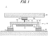
- FIG. 1 is a main cross-section of an example configuration of a tactile sensation providing apparatus 1 according to the first embodiment.
- the tactile sensation providing apparatus 1 according to the present embodiment includes an actuator 10, a housing (base) 20, and an object of vibration 30.
- the actuator 10 includes a piezoelectric element 11, a vibration plate 12, supports 13, connectors 14, a holder 15, a first fixing portion 17a, and a second fixing portion 17b.
- the actuator 10 includes two of the first fixing portions 17a.
- the actuator 10 is joined to the housing 20 by the first fixing portions 17a coupled to the connectors 14.
- the actuator 10 is joined to the object of vibration 30 by the second fixing portion 17b coupled to the holder 15.
- FIGS. 2A and 2B are perspective views of an example configuration of the actuator 10.
- FIG. 2A is a perspective view from the side joined to the housing 20.
- FIG. 2B is a perspective view from the side to which the object of vibration 30 is joined.
- Each portion of the actuator 10 is described with reference to FIGS. 1 , 2A, and 2B .
- the piezoelectric element 11 is, for example, rectangular.
- the piezoelectric element 11 expands and contracts in the longitudinal direction in a variety of patterns in accordance with an applied voltage signal.
- the piezoelectric element 11 may be a piezoelectric film or piezoelectric ceramic. Piezoelectric ceramic can generate vibration having a greater vibration energy than piezoelectric film can.
- the piezoelectric element 11 When the piezoelectric element 11 deforms in response to pressure from an external source, the piezoelectric element 11 outputs a voltage signal having a magnitude of voltage (voltage value) with the electric characteristic of corresponding to the magnitude of the load (force) due to the press on the piezoelectric element 11 or the rate of change (acceleration) in the magnitude of the load (force).
- the voltage signal output from the piezoelectric element 11 is, for example, transmitted to a controller of the device in which the actuator 10 is used.
- the controller of the device can control the device in accordance with the acquired voltage signal.
- the vibration plate 12 is a rectangular plate-shaped member having a predetermined thickness.
- the vibration plate 12 is, for example, a thin plate with elasticity.
- the vibration plate 12 includes, for example, metal, resin, or a composite material of metal, resin, and the like.
- the vibration plate 12 may be a thin metal plate (sham).
- the surface of the vibration plate 12 facing the housing 20 is referred to below as a first surface 12a.
- the surface of the vibration plate 12 facing the object of vibration 30 is referred to as a second surface 12b.
- the piezoelectric element 11 is provided on the first surface 12a of the vibration plate 12.
- the piezoelectric element 11 is arranged so that the longitudinal direction of the piezoelectric element 11 matches the longitudinal direction of the vibration plate 12.
- the holder 15 is provided on the second surface 12b of the vibration plate 12. The piezoelectric element 11 and the holder 15 are each joined to the vibration plate 12 by a method such as adhesion.
- a structure in which the piezoelectric element 11 is provided on the first surface 12a of the vibration plate 12 is known as a monomorph.
- a monomorph the expansion and contraction of the piezoelectric element 11 provokes bending vibration of the vibration plate 12.
- the vibration plate 12 vibrates with the amplitude in the normal direction of the first surface 12a being maximized at the other end of the vibration plate 12.
- both ends of the vibration plate 12 are supported by the housing 20, the vibration plate 12 vibrates with the amplitude in the normal direction of the first surface 12a being maximized near the center of the vibration plate 12.
- a support 13 is provided at each end of the vibration plate 12 in the longitudinal direction.
- the supports 13 maintain a clearance between the piezoelectric element 11 and the housing 20 to prevent the piezoelectric element 11 from hitting the housing 20 when the vibration plate 12 vibrates in accordance with displacement of the piezoelectric element 11.
- the supports 13 are, for example, thin plates with elasticity like the vibration plate 12.
- the supports 13 are made of the same material as the vibration plate 12.
- the supports 13 may, however, be made of a different material from the vibration plate 12. As described above, when both ends of the vibration plate 12 are supported, the vibration plate 12 vibrates in accordance with displacement of the piezoelectric element 11, with the amplitude being maximized near the center of the vibration plate 12.
- each support 13 is connected to the vibration plate 12.
- the other end of each support 13 is connected to one of the connectors 14.
- the connector 14 is connected to the support 13 and the first fixing portion 17a.
- the actuator 10 need not include the connectors 14.
- the connectors 14 are, for example, thin plates with elasticity like the vibration plate 12.
- the connectors 14 may be made of the same or different material as the vibration plate 12.
- the holder 15 is connected to the object of vibration 30 by the second fixing portion 17b.
- the holder 15 has, for example, a T-shaped cross-section as illustrated in FIG. 1 .
- the holder 15 is, for example, made of metal.
- the holder 15 may be made of a material other than metal, such as a rubber material.
- the holder 15 is provided on the second surface 12b of the vibration plate 12.
- the holder 15 is joined to the vibration plate 12 using a method such as adhesion.
- the holder 15 is provided near the center of the second surface 12b. However, the position at which the holder 15 is provided is not limited to being near the center.
- the holder 15 may be provided at the portion where the amplitude of the vibration plate 12 is maximized.
- the holder 15 has the object of vibration 30 joined thereto by a method such as adhesion, for example.
- the holder 15 When the holder 15 is made of a rubber material, the holder 15 may have a large elastic modulus in the vibration direction of the vibration plate 12, i.e. in the normal direction of the first surface 12a, to efficiently transmit vibration of the vibration plate 12 to the object of vibration 30. On the other hand, the holder 15 may have a small elastic modulus in a direction parallel to the first surface 12a of the vibration plate 12. This configuration reduces the likelihood of damage to the tactile sensation providing apparatus 1 due to an external force.
- the elastic modulus is a constant indicating the relationship between an external force acting on a member and the amount of displacement of the member. The product of the amount of displacement and the elastic modulus represents the external force. In other words, the same external force produces a larger amount of displacement as the elastic modulus is smaller.
- the holder 15 is made of the same material as the vibration plate 12.
- the holder 15 may, however, be made of a different material from the vibration plate 12.
- the vibration plate 12, the supports 13, the connectors 14, and the holder 15 are integrally molded.
- the member in which the vibration plate 12, the supports 13, the connectors 14, and the holder 15 are integrally molded is also referred to below as a frame 10a of the actuator 10.
- the frame 10a according to the present embodiment is made of the same material throughout.
- the frame 10a may, for example, be integrally molded by subjecting a thin sheet of metal to sheet-metal processing to bend the thin sheet.
- the frame 10a may be integrally molded by welding the vibration plate 12, the supports 13, the connectors 14, and the holder 15 together.
- the frame 10a may be made by integrally molding resin.
- the first fixing portions 17a fix the frame 10a to the housing 20.
- the second fixing portion 17b fixes the frame 10a to the object of vibration 30.
- the first fixing portions 17a and the second fixing portion 17b include, for example, metal, resin, or a composite material of metal, resin, and the like.
- the first fixing portions 17a and the second fixing portion 17b may, for example, be made of the same material as the frame 10a.
- the first fixing portions 17a and the second fixing portion 17b are, for example, plate-shaped.
- the first fixing portions 17a and the second fixing portion 17b are each displaceable in a direction intersecting the expansion and contraction direction of the piezoelectric element 11.
- the first fixing portions 17a and the second fixing portion 17b are connected to the frame 10a so that the planes of the first fixing portions 17a and the second fixing portion 17b are displaceable in a direction orthogonal to the expanding and contracting direction of the piezoelectric element 11 and orthogonal to the direction of bending vibration of the vibration plate 12.
- the first fixing portions 17a and the second fixing portion 17b each include a screw hole 17c for fixing the frame 10a to the housing 20 and the object of vibration 30.
- the method of fixing the frame 10a to the housing 20 and the object of vibration 30 is not limited to screwing.
- the frame 10a may, for example, be fixed to the housing 20 and the object of vibration 30 by adhesion.
- the first fixing portions 17a and the second fixing portion 17b need not include the holes 17c. At least a portion of the first fixing portions 17a and the second fixing portion 17b is exposed from the housing 20 and the object of vibration 30 of the actuator 10 when the first fixing portions 17a and the second fixing portion 17b are fixed to the housing 20 and the object of vibration 30.
- first fixing portions 17a and the second fixing portion 17b is fixed to the housing 20 and the object of vibration 30 so as to maintain a clearance between the frame 10a and the housing 20 and between the frame 10a and the object of vibration 30.
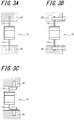
- FIGS. 3A to 3C illustrate example methods of fixing the actuator 10 via the first fixing portions 17a and the second fixing portion 17b.
- FIGS. 3A to 3C are views of the actuator 10 from one side (from the side of one of the supports 13).
- the portion of the first fixing portions 17a inserted inside the housing 20 and the portion of the second fixing portion 17b inserted inside the object of vibration 30 are also depicted in FIGS. 3A to 3C .
- the actuator 10 may, for example, be fixed to the housing 20 and the object of vibration 30 by inserting the first fixing portions 17a and the second fixing portion 17b into grooves formed in the housing 20 and the object of vibration 30, as illustrated in FIG. 3A .
- the first fixing portions 17a and the second fixing portion 17b need not include the holes 17c.
- the actuator 10 may, for example, be fixed to the housing 20 and the object of vibration 30 by inserting the first fixing portions 17a and the second fixing portion 17b into grooves formed in the housing 20 and the object of vibration 30 and screwing the first fixing portion 17a and the second fixing portion 17b in place through the holes 17c, as illustrated in FIG. 3B .
- the first fixing portions 17a and the second fixing portion 17b may, for example, be formed to be L-shaped in a side view.
- the actuator 10 may then be fixed to the housing 20 and the object of vibration 30 by screwing the first fixing portions 17a and the second fixing portion 17b onto the surface of the housing 20 and the object of vibration 30, as illustrated in FIG. 3C .
- first fixing portions 17a and the second fixing portion 17b are screwed onto the surface of the housing 20 and the object of vibration 30, as illustrated in FIG. 3C , then grooves for insertion of the first fixing portions 17a and the second fixing portion 17b need not be formed in the housing 20 and the object of vibration 30.
- the actuator 10 is joined to the housing 20 at the first fixing portions 17a that are connected to the connectors 14.
- the housing 20 has a greater mass and a higher rigidity than the actuator 10 does. In the present embodiment, the housing 20 is therefore considered to be a rigid body.
- the object of vibration 30 may, for example, be a touch sensor 50 provided in a device (see FIG. 3 ) or a switch.
- the actuator 10 is joined to the object of vibration 30 at the second fixing portion 17b connected to the holder 15.
- the vibration generated by the actuator 10 is mainly transmitted to the object of vibration 30.
- the object of vibration 30 can provide a tactile sensation to the user touching the object of vibration 30.
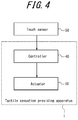
- FIG. 4 illustrates an example of the functional blocks of the tactile sensation providing apparatus 1 according to the present embodiment.
- the tactile sensation providing apparatus 1 includes the above-described actuator 10 and a controller 40.
- the controller 40 may be constituted by a processor, microcomputer, or the like capable of executing application software.
- the controller 40 may appropriately include a storage unit or the like constituted by memory or the like capable of storing various information as necessary.
- the controller 40 connects to the actuator 10.
- the controller 40 outputs a drive signal to the actuator 10.
- the drive signal is a voltage signal that is applied to the piezoelectric element 11 of the actuator 10.
- the piezoelectric element 11 expands and contracts in the longitudinal direction in accordance with the drive signal acquired from the controller 40.
- the vibration plate 12 of the example actuator 10 illustrated in FIGS. 1 , 2A, and 2B bends in accordance with displacement of the piezoelectric element 11.
- the vibration plate 12 bends so that the second surface 12b becomes convex.
- the vibration plate 12 bends so that the first surface 12a becomes convex. Displacement of the piezoelectric element 11 is thus converted into vibration in the normal direction of the first surface 12a of the vibration plate 12.
- the piezoelectric element 11 is displaced only in the contracting direction in response to application of a voltage signal.
- the vibration plate 12 oscillates between a state in which the second surface 12b is bent to become convex and a flat, unbent state.
- the piezoelectric element 11 is not limited to being displaced in the contracting direction in response to application of a voltage signal.
- the piezoelectric element 11 may be configured to be displaced in the expanding direction in response to application of a voltage signal or to be displaced in both the expanding direction and the contracting direction.
- the controller 40 drives the actuator 10 and vibrates the vibration plate 12. Vibration of the vibration plate 12 is transmitted to the object of vibration 30 through the holder 15. A tactile sensation is thus provided to the user touching the object of vibration 30.
- the controller 40 may connect to the touch sensor 50.
- the controller 40 may output a drive signal to the actuator 10 in response to a signal acquired from the touch sensor 50.
- the touch sensor 50 may be the object of vibration 30 of the tactile sensation providing apparatus 1.
- a touch by the user on the object of vibration 30 is detected by the touch sensor 50.
- the controller 40 vibrates the object of vibration 30 when the user is touching the object of vibration 30.
- the touch sensor 50 may be provided as a separate structure from the object of vibration 30 of the tactile sensation providing apparatus 1.
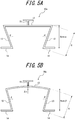
- FIGS. 5A and 5B illustrate an example cross-sectional shape of the frame 10a of the actuator 10 according to the present embodiment.
- the frame 10a of the actuator 10 elastically deforms in response to driving of the actuator 10.
- FIG. 5A illustrates the shape of the frame 10a when the actuator 10 is not being driven.
- FIG. 5B illustrates the shape of the frame 10a when the actuator 10 is being driven.
- the vibration plate 12 in FIG. 5B is bent in accordance with driving of the actuator 10 so that the second surface 12b becomes convex.
- each support 13 is arranged so that when the actuator 10 is not driven, the end of each support 13 at the side connected to the vibration plate 12 is further outward than the end at the side connected to the connector 14.
- the supports 13 arranged in this way are also referred to as being inclined outward. In this case, the angle between the vibration plate 12 and the support 13 is acute.
- the support 13 is arranged so that the angle between the normal direction of the vibration plate 12 and the support 13 becomes ⁇ .
- the angle ( ⁇ ) is also referred to below as a given angle ( ⁇ ).
- the given angle ( ⁇ ) is defined as a positive value when the support 13 is inclined outward relative to the normal direction of the vibration plate 12.
- the given angle ( ⁇ ) is measured in radians. Unless otherwise noted, the units of angles in the explanation below are also radians.
- the given angle ( ⁇ ) is assumed to satisfy - ⁇ ⁇ ⁇ ⁇ ⁇ to uniquely represent the direction in which the support 13 is arranged.
- the length of the support 13 is H.
- the distance between the end of the vibration plate 12 and the connector 14 is Hcos ⁇ .
- the distance between the end of the vibration plate 12 and the connector 14 is defined as the length of a perpendicular from the end of the vibration plate 12 to a surface including the connector 14.
- the vibration plate 12 bends when the actuator 10 is being driven.
- the displacement of the central portion of the vibration plate 12 relative to the ends is ⁇ x ( ⁇ x > 0) assuming that the displacement from the first surface 12a side towards the second surface 12b side is positive.
- the upper end of the support 13 (the end at the side connected to the vibration plate 12) is pulled by the vibration plate 12 towards the central portion of the vibration plate 12.
- the angle ( ⁇ ) is also referred to below as a displacement angle ( ⁇ ).
- the displacement angle ( ⁇ ) is defined as a positive value when the support 13 is inclined outward.
- the displacement angle ( ⁇ ) is assumed to satisfy - ⁇ ⁇ ⁇ ⁇ ⁇ .
- the actuator 10 When the actuator 10 is driven, the upper end of the support 13 is pulled towards the central portion of the vibration plate 12. Hence, ⁇ and ⁇ satisfy the relationship ⁇ > ⁇ .
- the length of the support 13 is H, as in FIG. 5A . In this case, the distance between the end of the vibration plate 12 and the connector 14 is Hcos ⁇ .
- Equation (1) H cos ⁇ ⁇ cos ⁇
- Equation (1) ⁇ > ⁇ > 0 and H > 0. Hence, ⁇ y > 0.
- FIGS. 6A and 6B illustrate cross-sectional shapes of a frame 10b of an actuator 10 according to a comparative example.
- the frame 10b is a member constituted by the holder 15 and the integrally molded vibration plate 12, supports 13, and connectors 14.
- the frame 10b has a different cross-sectional shape than the frame 10a does.
- FIG. 6A illustrates the shape of the frame 10b when the actuator 10 is not being driven.
- FIG. 6B illustrates the shape of the frame 10b when the actuator 10 is being driven.
- the vibration plate 12 in FIG. 6B is bent in accordance with driving of the actuator 10 so that the second surface 12b becomes convex.
- the supports 13 of the frame 10b are positioned to lie in the normal direction of the vibration plate 12 when the actuator 10 is not being driven. In other words, the supports 13 are orthogonal to the vibration plate 12 in FIG. 6A .
- the length of the support 13 is H. In this case, the distance between the end of the vibration plate 12 and the connector 14 is the same as the length (H) of the support 13.
- FIG. 6B illustrates the case of the actuator 10 being driven.
- the vibration plate 12 bends so that the central portion of the vibration plate 12 is displaced relative to the ends by ⁇ x at the second surface 12b side.
- the relationship ⁇ x > 0 is satisfied assuming that the displacement from the first surface 12a side towards the second surface 12b is positive.
- the upper end of the support 13 (the end at the side connected to the vibration plate 12) is pulled by the vibration plate 12 towards the central portion of the vibration plate 12.
- the displacement angle of the support 13 is ⁇ (where ⁇ ⁇ 0 as defined above).
- the length of the support 13 is H, as in FIG. 5A .
- the distance between the end of the vibration plate 12 and the connector 14 is Hcos ⁇ .
- Equation (2) H cos ⁇ ⁇ 1
- Equation (2) cos ⁇ ⁇ 1 and H > 0. Hence, ⁇ y ⁇ 0.
- the support 13 thus has a given angle ( ⁇ ) in the cross-sectional shape of the frame 10a according to the present embodiment.
- ⁇ the angle between the vibration plate 12 and the support 13 is acute.
- the displacement of the actuator 10 transmitted to the object of vibration 30 does not increase when the angle between the vibration plate 12 and the support 13 is a right angle, as in the cross-sectional shape of the frame 10b according to the comparative example.
- the displacement of the actuator 10 transmitted to the object of vibration 30 clearly does not increase when the angle between the vibration plate 12 and the support 13 is obtuse, either.
- the frame 10a according to the present embodiment increases the displacement of the actuator 10 transmitted to the object of vibration 30.
- FIGS. 7A and 7B are views of the actuator 10 from one side (from the side of one of the supports 13).
- the actuator 10 according to the present embodiment is fixed in a state such that a portion of the first fixing portions 17a is inserted in the housing 20, and a portion of the second fixing portion 17b is inserted in the object of vibration 30, for example as illustrated in FIG. 3A .
- the actuator 10 vibrates when the piezoelectric element 11 is driven, for example, thereby vibrating the object of vibration 30 in the vertical direction in FIG. 7A .
- FIG. 7B illustrates the state when shear stress acts on the actuator 10.
- shear stress acts on the actuator 10 when the housing 20 and the object of vibration 30 shift in opposite directions to the left and right from the state illustrated in FIG. 7A .
- the portion of the first fixing portions 17a exposed from the housing 20 and the portion of the second fixing portion 17b exposed from the object of vibration 30 deform due to the elasticity of the first fixing portions 17a and the second fixing portion 17b in accordance with the stress in the shearing direction.
- the piezoelectric element 11 is driven in this state, the vibration of the vibration plate 12 is converted into vibration in a direction perpendicular to the housing 20 and the object of vibration 30 by the deformed first fixing portions 17a and second fixing portion 17b.
- the object of vibration 30 thus vibrates in the vertical direction of FIG. 7B .
- the actuator 10 of the present embodiment can tolerate shear stress via the first fixing portions 17a and the second fixing portion 17b.
- FIGS. 8A and 8B are cross-sections of a terminal illustrating an example of mounting the actuator 10 in FIG. 1 in a terminal.
- a terminal 60 includes a body 61 and a panel 62 disposed on the upper side of the body 61.
- the body 61 is, for example, formed by metal or hard plastic.
- the body 61 has the appearance of a substantially rectangular parallelepiped, for example, and includes a recess for the panel 62.
- the body 61 corresponds to the housing 20 illustrated in FIG. 1 .
- the panel 62 is a touch panel that detects contact, a cover panel for protecting a display provided in the terminal 60, or the like.
- the panel 62 is, for example, formed by glass or synthetic resin such as acrylic.
- the panel 62 is a substantially rectangular parallelepiped, for example.
- the panel 62 may be a plate or may be a curved panel, the surface of which is gradually inclined.
- the panel 62 corresponds to the object of vibration 30 in FIG. 1 .
- the body 61 includes projections 61a, shaped substantially like right triangles, at the bottom of the recess.
- the panel 62 includes projections 62a, shaped substantially like right triangles, on the side at the bottom when the panel 62 is disposed in the body 61.
- the body 61 and the panel 62 are coupled via support members 63 at inclined surfaces formed by the projections 61a and the projections 62a.
- the support members 63 are, for example, formed from an elastic material such as rubber.
- the actuator 10 is connected between the body 61 and the panel 62.
- the actuator 10 is connected between the body 61 and the panel 62 by the first fixing portions 17a and the second fixing portion 17b being inserted between the side of the body 61 formed by the recess and the side of the panel 62 when the panel 62 is disposed in the body 61.
- the vibration of the actuator 10 is transmitted to the panel 62, and the panel 62 vibrates.
- the panel 62 vibrates in a diagonal direction, from the lower left to the upper right, along the inclined surface of the projections 61a and 62a, as indicated by the arrows in FIG. 8B .
- the first fixing portions 17a and second fixing portion 17b of the actuator 10 deform in reaction to the shear stress generated by the press.
- the actuator 10 can easily subject the panel 62 to a desired vibration. In this way, the actuator 10 can tolerate shear stress via the first fixing portions 17a and the second fixing portion 17b.
- the panel 62 was described as vibrating in a diagonal direction along the inclined surface of the projections 61a and 62a, but the vibration direction of the panel 62 is not limited to this direction.
- the body 61 and the panel 62 do not include the respective projections 61a and 62a, and the panel 62 is coupled to the bottom of the recess of the body 61 via the support members 63, for example, then the panel 62 vibrates in a direction along the surface of the panel 62 (the lateral direction in FIGS. 8A and 8B ).
- the panel 62 vibrates in a direction perpendicular to the surface of the panel 62 (the longitudinal direction in FIGS. 8A and 8B ) as a result of vibration of the actuator 10.
- the actuator 10 can tolerate shear stress by deformation of the first fixing portions 17a and the second fixing portion 17b.
- the actuator 100 might not be able to provide the panel 62 with a desired vibration upon occurrence of a shear stress that is based on the positional relationship between the body 61 and the panel 62.
- the first fixing portions 17a and second fixing portion 17b in the actuator 10 according to the present embodiment deform when a shear stress acts on the actuator 10.
- the actuator 10 can therefore easily provide the object of vibration 30 with a desired vibration even when shear stress occurs.
- FIG. 9 is a main cross-section of an example configuration of a tactile sensation providing apparatus 1 according to the second embodiment. A description of matter identical to the first embodiment is omitted as appropriate to focus mainly on the differences.
- the vibration plate 12, connectors 14, and holder 15 of the present embodiment are, for example, thin plates with elasticity as in the first embodiment.
- the material of the vibration plate 12, the material of the connectors 14, and the material of the holder 15 may be the same or different.
- the supports 13 are pillars made of curable resin, for example, and are members with a large elastic modulus in the normal direction of the vibration plate 12.
- the supports 13 may be made of another material, such as metal.
- the supports 13 are configured to elastically deform at the joint with the vibration plate 12 and the joint with the connector 14. The supports 13 can therefore move so as to incline.
- the vibration plate 12 and the supports 13 are different materials that are integrally molded together.
- the vibration plate 12 and the supports 13 may be integrally molded by being welded together.
- the vibration plate 12 and the supports 13 may be integrally molded by molding resin that becomes the supports 13 around a metal vibration plate 12.
- the vibration plate 12 and the supports 13 may also be integrally molded by providing fitting portions in a metal vibration plate 12 and then engaging supports 13 made of resin with the fitting portions.
- the vibration plate 12 and the supports 13 may also be integrally molded by providing a joining face, with primer applied thereto, on a surface of a metal vibration plate 12 and molding resin onto the joining face.
- the vibration plate 12 and the supports 13 may also be integrally molded by providing a joining face, on which microfabrication has been performed, on a surface of a metal vibration plate 12 and molding resin onto the joining face.
- the vibration plate 12 and the supports 13 made of different materials are integrally molded in the actuator 10 according to the present embodiment.
- the present embodiment allows a reduction in the number of components and assembly steps while the supports 13 reduce attenuation of the vibration of the vibration plate 12 generated in accordance with displacement of the piezoelectric element 11.
- the actuator 10 according to the present embodiment can lengthen the mean time between failure (MTBF) and improve the yield at the time of assembly.
- MTBF mean time between failure
- the actuator 10 according to the present embodiment can further increase the displacement of the actuator 10 transmitted to the object of vibration 30 as compared to when the angle between the vibration plate 12 and the support 13 is not acute.
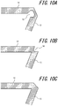
- FIGS. 10A, 10B, and 10C illustrate examples of the cross-sectional shape of a joint between the vibration plate 12 and the support 13.
- FIG. 10A illustrates an example of the cross-sectional shape when a notch 16 is provided on the inside of the joint (the side that connects to the first surface 12a of the vibration plate 12).
- FIG. 10B illustrates an example of the cross-sectional shape when a notch 16 is provided on the outside of the joint (the side that connects to the second surface 12b of the vibration plate 12).
- FIG. 10C illustrates a comparative example in which a notch 16 is not provided on the inside or the outside.
- the joint between the vibration plate 12 and the support 13 in FIGS. 10A and 10B bends more easily than the example illustrated in FIG. 10C by virtue of the notch 16 being provided.
- the upper portion of the support 13 is therefore pulled towards the central portion of the vibration plate 12 more easily, preventing bending of the vibration plate 12 from being impeded when the actuator 10 is driven.
- the notch 16 illustrated in FIGS. 10A and 10B may be provided in the joint between the support 13 and the connector 14. This configuration can increase the difference between the given angle ( ⁇ ) and the displacement angle ( ⁇ ) of the support 13.
- FIGS. 11A and 11B illustrate examples of a support 13 provided with a rib 13a.
- FIG. 11A illustrates an example cross-sectional shape of the frame 10a of the actuator 10.
- FIG. 11B is a cross-section along the A-A line in FIG. 11A .
- Provision of the rib 13a in the support 13 as illustrated in FIG. 11B increases the rigidity of the support 13 relative to the normal direction of the vibration plate 12. In other words, this configuration can reduce the amount of deformation of the support 13 due to the force acting on the support 13 as a reaction to the force that the actuator 10 exerts on the object of vibration 30.
- the vibration generated by the actuator 10 thus tends to be absorbed less by the support 13. Consequently, the vibration generated by the actuator 10 is transmitted more efficiently to the object of vibration 30.
- the supports 13 may be configured so that the ends of the vibration plate 12 are displaced more in the longitudinal direction than in the normal direction of the vibration plate 12 in accordance with expansion and contraction of the piezoelectric element 11. When the supports 13 are thus configured for smaller displacement of the ends of the vibration plate 12 in the normal direction of the vibration plate 12, the vibration of the vibration plate 12 is efficiently transmitted to the object of vibration 30. When the supports 13 are configured for greater displacement of the ends of the vibration plate 12 in the longitudinal direction of the vibration plate 12, attenuation of the vibration of the vibration plate 12 is reduced.
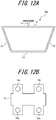
- FIGS. 12A and 12B illustrate examples of frames 10a in which the connectors 14 at either side are bent inward and connected.
- FIG. 12A illustrates the cross-sectional shape of the frame 10a.
- FIG. 12B is a plan view of the frame 10a.
- the cross-sectional shape of the frame 10a becomes trapezoidal as a result of the connectors 14 being connected as in FIG. 12A .
- This structure increases the strength of the frame 10a as compared to when the connectors 14 are formed separately.
- screw holes 14a are provided beside the fixing portions 14 to facilitate screwing of the connectors 14 to the housing 20.
- FIGS. 13A and 13B illustrate example dimensions of each part at the time of driving of the actuator 10.
- an example of calculating the displacement of the central portion of the vibration plate 12 when the actuator 10 is driven is described with reference to FIGS. 13A and 13B .
- the holder 15 is omitted in FIGS. 13A and 13B .
- FIG. 13A illustrates example dimensions of each part when the actuator 10 is not being driven.
- the longitudinal dimension of the piezoelectric element 11 is L.
- the piezoelectric element 11 is disposed at a distance (M) from each end of the vibration plate 12.
- the longitudinal dimension of the vibration plate 12 is L + 2M.
- the length of the support 13 is H.
- the angle (given angle) formed by the support 13 and the normal direction of the vibration plate 12 is ⁇ .
- the ends of the supports 13 coupled to the connectors 14 are fixed by the connectors 14.
- the supports 13 are pivotable about the ends of the supports 13.
- FIG. 13B illustrates example dimensions of each part when the actuator 10 is driven.
- the vibration plate 12 bends so that the second surface 12b becomes convex (see FIG. 1 ).
- the shape of the vibration plate 12 and the support 13 when the actuator 10 is not being driven is indicated in FIG. 13B by dashed double-dotted lines.
- the displacement ( ⁇ x) of the central portion of the vibration plate 12 relative to the ends (the joints between the vibration plate 12 and the supports 13) is given by Equation (3) below.
- ⁇ x Msin ⁇ + ⁇ 1 ⁇ cos ⁇
- Equation (3) ⁇ is the radius of curvature when the vibration plate 12 bends, and ⁇ is the difference in the angle between the bent state and the unbent state at the ends of the vibration plate 12.
- the interior angle of the bent portion of the vibration plate 12, i.e. the interior angle of the sector having the bent portion as an arc, is expressed as 2 ⁇ .
- the radius of curvature ( ⁇ ) and the interior angle (2 ⁇ ) are determined by factors such as the amount of displacement of the piezoelectric element 11 or the ratio between the thickness of the piezoelectric element 11 and the thickness of the vibration plate 12.
- Equation (4) an approximation based on the Taylor expansion of a trigonometric function is used, taking ⁇ , ⁇ , and ⁇ to be minute values.
- ⁇ ⁇
- ⁇ ⁇
- sin ⁇ ⁇ ⁇ ⁇ sin ⁇ ⁇ ⁇
- sin ⁇ ⁇ L/2 ⁇ it is assumed that sin ⁇ ⁇ L/2 ⁇ .
- the displacement ( ⁇ z) of the central portion of the vibration plate 12 is the sum of ⁇ x and ⁇ y. Accordingly, the displacement ( ⁇ z) of the central portion of the vibration plate 12 illustrated in FIG. 13B is given by Equation (7) below, which is based on Equation (3) and Equation (6).
- Equation (7) Msin ⁇ + ⁇ 1 ⁇ cos ⁇ + H 1 ⁇ cos ⁇
- Equation (1) On the basis of Equation (1), the relationship ⁇ y > 0 is satisfied when the given angle ( ⁇ ) and the displacement angle ( ⁇ ) satisfy the relationship cos ⁇ ⁇ cos ⁇ .
- the relationship ⁇ > ⁇ is satisfied in the actuator 10 according to the first embodiment and the like.
- ⁇ y > 0 if ⁇ ⁇ 0.
- Equation (8) Equation (8) below represents a sufficient condition on the given angle ( ⁇ ) for the relationship ⁇ y > 0 to be satisfied.
Landscapes
- Engineering & Computer Science (AREA)
- General Engineering & Computer Science (AREA)
- Theoretical Computer Science (AREA)
- Physics & Mathematics (AREA)
- Human Computer Interaction (AREA)
- General Physics & Mathematics (AREA)
- Electromagnetism (AREA)
- Mechanical Engineering (AREA)
- Apparatuses For Generation Of Mechanical Vibrations (AREA)
- User Interface Of Digital Computer (AREA)
- General Electrical Machinery Utilizing Piezoelectricity, Electrostriction Or Magnetostriction (AREA)
Abstract
Description
- The present application claims priority to and the benefit of Japanese Patent Application No.
2016-062446 filed March 25, 2016 - The present disclosure relates to an actuator and a tactile sensation providing apparatus.
- A touch sensor or the like provided with an actuator that generates vibration is known. For example, see patent literature (PTL) 1. In this touch sensor or the like, the actuator vibrates an object of vibration, such as the touch sensor, thereby providing a tactile sensation to a user who touches the object of vibration.
- PTL 1:
JP5452729B2 - An actuator according to an embodiment includes a piezoelectric element, a vibration plate, a support, a holder, a first fixing portion, and a second fixing portion. The vibration plate has the piezoelectric element joined thereto and is configured to bend and vibrate in accordance with expansion and contraction of the piezoelectric element. The support is configured to support the vibration plate on a base to allow bending and vibration of the vibration plate. The holder is configured to hold an object of vibration to the vibration plate. The first fixing portion is coupled to the support and configured to fix the support to the base. The second fixing portion is coupled to the holder and configured to fix the object of vibration to the holder. The first fixing portion and the second fixing portion are each displaceable in a direction intersecting a direction of the expansion and contraction of the piezoelectric element.
- A tactile sensation providing apparatus according to an embodiment includes a base, an object of vibration, and an actuator. The actuator includes a piezoelectric element, a vibration plate, a support, a holder, a first fixing portion, and a second fixing portion. The vibration plate has the piezoelectric element joined thereto and is configured to bend and vibrate in accordance with expansion and contraction of the piezoelectric element. The support is configured to support the vibration plate on the base to allow bending and vibration of the vibration plate. The holder is configured to hold the object of vibration to the vibration plate. The first fixing portion is coupled to the support and configured to fix the support to the base. The second fixing portion is coupled to the holder and configured to fix the object of vibration to the holder. The first fixing portion and the second fixing portion are each displaceable in a direction intersecting a direction of the expansion and contraction of the piezoelectric element.
- In the accompanying drawings:
-
FIG. 1 is a main cross-section of an example configuration of a tactile sensation providing apparatus according to a first embodiment; -
FIGS. 2A and 2B are perspective views of an example configuration of the actuator inFIG. 1 ; -
FIGS. 3A, 3B, and 3C illustrate example methods of fixing an actuator via fixing portions; -
FIG. 4 is a functional block diagram illustrating an example of the schematic configuration of the tactile sensation providing apparatus inFIG. 1 ; -
FIGS. 5A and 5B illustrate example cross-sectional shapes of a frame of the actuator inFIG. 1 ; -
FIGS. 6A and 6B illustrate cross-sectional shapes of a frame of an actuator according to a comparative example; -
FIGS. 7A and 7B illustrate operations of an actuator fixed to a housing and to an object of vibration; -
FIGS. 8A and 8B are cross-sections of a terminal illustrating an example of mounting the actuator inFIG. 1 in a terminal; -
FIG. 9 illustrates an example cross-sectional shape of a frame of an actuator according to a second embodiment; -
FIGS. 10A, 10B, and 10C illustrate example cross-sectional shapes of a joint between a vibration plate and a support; -
FIGS. 11A and 11B illustrate an example support provided with a rib; -
FIGS. 12A and 12B illustrate example frames in which connectors at either side are bent inward and connected; and -
FIGS. 13A and 13B illustrate example dimensions of each part when an actuator is driven. - An apparatus for providing a tactile sensation provides a tactile sensation efficiently to a user by increasing the vibration of an actuator. The present disclosure relates to an actuator and a tactile sensation providing apparatus that can increase generated vibration.
- An actuator and tactile sensation providing apparatus according to embodiments of the present disclosure are described below in detail with reference to the drawings.
- A tactile sensation providing apparatus according to a first embodiment may be used in a variety of devices. The tactile sensation providing apparatus according to the present embodiment may be an on-vehicle device such as a car navigation system, a steering wheel, or a power window switch. The tactile sensation providing apparatus may also be a mobile phone, a smartphone, a tablet personal computer (PC), a notebook PC, or the like. The tactile sensation providing apparatus is not limited to these examples and may be any of a variety of electronic devices, such as a desktop PC, a household appliance, an industrial device (factory automation (FA) device), a dedicated terminal, or the like. The drawings referred to below are schematic illustrations, and the dimensional ratios and the like in the drawings do not necessarily match the actual dimensions.
-
FIG. 1 is a main cross-section of an example configuration of a tactilesensation providing apparatus 1 according to the first embodiment. As illustrated inFIG. 1 , the tactilesensation providing apparatus 1 according to the present embodiment includes anactuator 10, a housing (base) 20, and an object ofvibration 30. - The
actuator 10 includes apiezoelectric element 11, avibration plate 12, supports 13,connectors 14, aholder 15, afirst fixing portion 17a, and asecond fixing portion 17b. In the present embodiment, theactuator 10 includes two of thefirst fixing portions 17a. Theactuator 10 is joined to thehousing 20 by thefirst fixing portions 17a coupled to theconnectors 14. Theactuator 10 is joined to the object ofvibration 30 by thesecond fixing portion 17b coupled to theholder 15. -
FIGS. 2A and 2B are perspective views of an example configuration of theactuator 10.FIG. 2A is a perspective view from the side joined to thehousing 20.FIG. 2B is a perspective view from the side to which the object ofvibration 30 is joined. Each portion of theactuator 10 is described with reference toFIGS. 1 ,2A, and 2B . - The
piezoelectric element 11 is, for example, rectangular. Thepiezoelectric element 11 expands and contracts in the longitudinal direction in a variety of patterns in accordance with an applied voltage signal. Thepiezoelectric element 11 may be a piezoelectric film or piezoelectric ceramic. Piezoelectric ceramic can generate vibration having a greater vibration energy than piezoelectric film can. - When the
piezoelectric element 11 deforms in response to pressure from an external source, thepiezoelectric element 11 outputs a voltage signal having a magnitude of voltage (voltage value) with the electric characteristic of corresponding to the magnitude of the load (force) due to the press on thepiezoelectric element 11 or the rate of change (acceleration) in the magnitude of the load (force). The voltage signal output from thepiezoelectric element 11 is, for example, transmitted to a controller of the device in which theactuator 10 is used. The controller of the device can control the device in accordance with the acquired voltage signal. - The
vibration plate 12 is a rectangular plate-shaped member having a predetermined thickness. Thevibration plate 12 is, for example, a thin plate with elasticity. Thevibration plate 12 includes, for example, metal, resin, or a composite material of metal, resin, and the like. Thevibration plate 12 may be a thin metal plate (sham). The surface of thevibration plate 12 facing thehousing 20 is referred to below as afirst surface 12a. The surface of thevibration plate 12 facing the object ofvibration 30 is referred to as asecond surface 12b. - The
piezoelectric element 11 is provided on thefirst surface 12a of thevibration plate 12. Thepiezoelectric element 11 is arranged so that the longitudinal direction of thepiezoelectric element 11 matches the longitudinal direction of thevibration plate 12. Theholder 15 is provided on thesecond surface 12b of thevibration plate 12. Thepiezoelectric element 11 and theholder 15 are each joined to thevibration plate 12 by a method such as adhesion. - A structure in which the
piezoelectric element 11 is provided on thefirst surface 12a of thevibration plate 12 is known as a monomorph. In a monomorph, the expansion and contraction of thepiezoelectric element 11 provokes bending vibration of thevibration plate 12. When only one end of thevibration plate 12 is supported by thehousing 20, thevibration plate 12 vibrates with the amplitude in the normal direction of thefirst surface 12a being maximized at the other end of thevibration plate 12. When both ends of thevibration plate 12 are supported by thehousing 20, thevibration plate 12 vibrates with the amplitude in the normal direction of thefirst surface 12a being maximized near the center of thevibration plate 12. - A
support 13 is provided at each end of thevibration plate 12 in the longitudinal direction. The supports 13 maintain a clearance between thepiezoelectric element 11 and thehousing 20 to prevent thepiezoelectric element 11 from hitting thehousing 20 when thevibration plate 12 vibrates in accordance with displacement of thepiezoelectric element 11. The supports 13 are, for example, thin plates with elasticity like thevibration plate 12. The supports 13 are made of the same material as thevibration plate 12. The supports 13 may, however, be made of a different material from thevibration plate 12. As described above, when both ends of thevibration plate 12 are supported, thevibration plate 12 vibrates in accordance with displacement of thepiezoelectric element 11, with the amplitude being maximized near the center of thevibration plate 12. - One end of each
support 13 is connected to thevibration plate 12. The other end of eachsupport 13 is connected to one of theconnectors 14. Theconnector 14 is connected to thesupport 13 and thefirst fixing portion 17a. When the supports 13 and thefirst fixing portions 17a can be connected directly, theactuator 10 need not include theconnectors 14. Theconnectors 14 are, for example, thin plates with elasticity like thevibration plate 12. Theconnectors 14 may be made of the same or different material as thevibration plate 12. - The
holder 15 is connected to the object ofvibration 30 by thesecond fixing portion 17b. Theholder 15 has, for example, a T-shaped cross-section as illustrated inFIG. 1 . Theholder 15 is, for example, made of metal. Theholder 15 may be made of a material other than metal, such as a rubber material. Theholder 15 is provided on thesecond surface 12b of thevibration plate 12. Theholder 15 is joined to thevibration plate 12 using a method such as adhesion. Theholder 15 is provided near the center of thesecond surface 12b. However, the position at which theholder 15 is provided is not limited to being near the center. Theholder 15 may be provided at the portion where the amplitude of thevibration plate 12 is maximized. Theholder 15 has the object ofvibration 30 joined thereto by a method such as adhesion, for example. - When the
holder 15 is made of a rubber material, theholder 15 may have a large elastic modulus in the vibration direction of thevibration plate 12, i.e. in the normal direction of thefirst surface 12a, to efficiently transmit vibration of thevibration plate 12 to the object ofvibration 30. On the other hand, theholder 15 may have a small elastic modulus in a direction parallel to thefirst surface 12a of thevibration plate 12. This configuration reduces the likelihood of damage to the tactilesensation providing apparatus 1 due to an external force. The elastic modulus is a constant indicating the relationship between an external force acting on a member and the amount of displacement of the member. The product of the amount of displacement and the elastic modulus represents the external force. In other words, the same external force produces a larger amount of displacement as the elastic modulus is smaller. - In the present embodiment, the
holder 15 is made of the same material as thevibration plate 12. Theholder 15 may, however, be made of a different material from thevibration plate 12. - In the present embodiment, the
vibration plate 12, thesupports 13, theconnectors 14, and theholder 15 are integrally molded. The member in which thevibration plate 12, thesupports 13, theconnectors 14, and theholder 15 are integrally molded is also referred to below as aframe 10a of theactuator 10. Theframe 10a according to the present embodiment is made of the same material throughout. Theframe 10a may, for example, be integrally molded by subjecting a thin sheet of metal to sheet-metal processing to bend the thin sheet. Theframe 10a may be integrally molded by welding thevibration plate 12, thesupports 13, theconnectors 14, and theholder 15 together. Theframe 10a may be made by integrally molding resin. - The
first fixing portions 17a fix theframe 10a to thehousing 20. Thesecond fixing portion 17b fixes theframe 10a to the object ofvibration 30. Thefirst fixing portions 17a and thesecond fixing portion 17b include, for example, metal, resin, or a composite material of metal, resin, and the like. Thefirst fixing portions 17a and thesecond fixing portion 17b may, for example, be made of the same material as theframe 10a. - The
first fixing portions 17a and thesecond fixing portion 17b are, for example, plate-shaped. Thefirst fixing portions 17a and thesecond fixing portion 17b are each displaceable in a direction intersecting the expansion and contraction direction of thepiezoelectric element 11. In the present embodiment, thefirst fixing portions 17a and thesecond fixing portion 17b are connected to theframe 10a so that the planes of thefirst fixing portions 17a and thesecond fixing portion 17b are displaceable in a direction orthogonal to the expanding and contracting direction of thepiezoelectric element 11 and orthogonal to the direction of bending vibration of thevibration plate 12. - The
first fixing portions 17a and thesecond fixing portion 17b each include ascrew hole 17c for fixing theframe 10a to thehousing 20 and the object ofvibration 30. The method of fixing theframe 10a to thehousing 20 and the object ofvibration 30 is not limited to screwing. Theframe 10a may, for example, be fixed to thehousing 20 and the object ofvibration 30 by adhesion. In this case, thefirst fixing portions 17a and thesecond fixing portion 17b need not include theholes 17c. At least a portion of thefirst fixing portions 17a and thesecond fixing portion 17b is exposed from thehousing 20 and the object ofvibration 30 of theactuator 10 when thefirst fixing portions 17a and thesecond fixing portion 17b are fixed to thehousing 20 and the object ofvibration 30. In other words, at least a portion of thefirst fixing portions 17a and thesecond fixing portion 17b is fixed to thehousing 20 and the object ofvibration 30 so as to maintain a clearance between theframe 10a and thehousing 20 and between theframe 10a and the object ofvibration 30. -
FIGS. 3A to 3C illustrate example methods of fixing theactuator 10 via thefirst fixing portions 17a and thesecond fixing portion 17b.FIGS. 3A to 3C are views of the actuator 10 from one side (from the side of one of the supports 13). For the sake of illustration, the portion of thefirst fixing portions 17a inserted inside thehousing 20 and the portion of thesecond fixing portion 17b inserted inside the object ofvibration 30 are also depicted inFIGS. 3A to 3C . - The
actuator 10 may, for example, be fixed to thehousing 20 and the object ofvibration 30 by inserting thefirst fixing portions 17a and thesecond fixing portion 17b into grooves formed in thehousing 20 and the object ofvibration 30, as illustrated inFIG. 3A . In this case, thefirst fixing portions 17a and thesecond fixing portion 17b need not include theholes 17c. - The
actuator 10 may, for example, be fixed to thehousing 20 and the object ofvibration 30 by inserting thefirst fixing portions 17a and thesecond fixing portion 17b into grooves formed in thehousing 20 and the object ofvibration 30 and screwing thefirst fixing portion 17a and thesecond fixing portion 17b in place through theholes 17c, as illustrated inFIG. 3B . - The
first fixing portions 17a and thesecond fixing portion 17b may, for example, be formed to be L-shaped in a side view. Theactuator 10 may then be fixed to thehousing 20 and the object ofvibration 30 by screwing thefirst fixing portions 17a and thesecond fixing portion 17b onto the surface of thehousing 20 and the object ofvibration 30, as illustrated inFIG. 3C . When thefirst fixing portions 17a and thesecond fixing portion 17b are screwed onto the surface of thehousing 20 and the object ofvibration 30, as illustrated inFIG. 3C , then grooves for insertion of thefirst fixing portions 17a and thesecond fixing portion 17b need not be formed in thehousing 20 and the object ofvibration 30. - As illustrated in
FIG. 1 andFIGS. 3A to 3C , theactuator 10 is joined to thehousing 20 at thefirst fixing portions 17a that are connected to theconnectors 14. Thehousing 20 has a greater mass and a higher rigidity than theactuator 10 does. In the present embodiment, thehousing 20 is therefore considered to be a rigid body. - The object of
vibration 30 may, for example, be atouch sensor 50 provided in a device (seeFIG. 3 ) or a switch. Theactuator 10 is joined to the object ofvibration 30 at thesecond fixing portion 17b connected to theholder 15. As described above, when thehousing 20 is considered to be a rigid body, the vibration generated by theactuator 10 is mainly transmitted to the object ofvibration 30. Hence, the object ofvibration 30 can provide a tactile sensation to the user touching the object ofvibration 30. -
FIG. 4 illustrates an example of the functional blocks of the tactilesensation providing apparatus 1 according to the present embodiment. As illustrated inFIG. 4 , the tactilesensation providing apparatus 1 includes the above-describedactuator 10 and acontroller 40. Thecontroller 40 may be constituted by a processor, microcomputer, or the like capable of executing application software. Thecontroller 40 may appropriately include a storage unit or the like constituted by memory or the like capable of storing various information as necessary. - As illustrated in
FIG. 4 , thecontroller 40 connects to theactuator 10. Thecontroller 40 outputs a drive signal to theactuator 10. The drive signal is a voltage signal that is applied to thepiezoelectric element 11 of theactuator 10. - The
piezoelectric element 11 expands and contracts in the longitudinal direction in accordance with the drive signal acquired from thecontroller 40. Thevibration plate 12 of theexample actuator 10 illustrated inFIGS. 1 ,2A, and 2B bends in accordance with displacement of thepiezoelectric element 11. In other words, when thepiezoelectric element 11 is displaced by contracting in the longitudinal direction of thevibration plate 12, thevibration plate 12 bends so that thesecond surface 12b becomes convex. When thepiezoelectric element 11 is displaced by expanding in the longitudinal direction of thevibration plate 12, thevibration plate 12 bends so that thefirst surface 12a becomes convex. Displacement of thepiezoelectric element 11 is thus converted into vibration in the normal direction of thefirst surface 12a of thevibration plate 12. - In the present embodiment, the
piezoelectric element 11 is displaced only in the contracting direction in response to application of a voltage signal. In this case, thevibration plate 12 oscillates between a state in which thesecond surface 12b is bent to become convex and a flat, unbent state. Thepiezoelectric element 11 is not limited to being displaced in the contracting direction in response to application of a voltage signal. Thepiezoelectric element 11 may be configured to be displaced in the expanding direction in response to application of a voltage signal or to be displaced in both the expanding direction and the contracting direction. - In this way, the
controller 40 drives theactuator 10 and vibrates thevibration plate 12. Vibration of thevibration plate 12 is transmitted to the object ofvibration 30 through theholder 15. A tactile sensation is thus provided to the user touching the object ofvibration 30. - As illustrated in
FIG. 4 , for example, thecontroller 40 may connect to thetouch sensor 50. In this case, thecontroller 40 may output a drive signal to theactuator 10 in response to a signal acquired from thetouch sensor 50. Thetouch sensor 50 may be the object ofvibration 30 of the tactilesensation providing apparatus 1. In this case, a touch by the user on the object ofvibration 30 is detected by thetouch sensor 50. Thecontroller 40 vibrates the object ofvibration 30 when the user is touching the object ofvibration 30. This configuration allows the tactilesensation providing apparatus 1 to provide a tactile sensation to the user touching the object ofvibration 30. Thetouch sensor 50 may be provided as a separate structure from the object ofvibration 30 of the tactilesensation providing apparatus 1. -
FIGS. 5A and 5B illustrate an example cross-sectional shape of theframe 10a of theactuator 10 according to the present embodiment. Theframe 10a of theactuator 10 elastically deforms in response to driving of theactuator 10.FIG. 5A illustrates the shape of theframe 10a when theactuator 10 is not being driven.FIG. 5B illustrates the shape of theframe 10a when theactuator 10 is being driven. Thevibration plate 12 inFIG. 5B is bent in accordance with driving of theactuator 10 so that thesecond surface 12b becomes convex. - As illustrated in
FIG. 5A , eachsupport 13 is arranged so that when theactuator 10 is not driven, the end of eachsupport 13 at the side connected to thevibration plate 12 is further outward than the end at the side connected to theconnector 14. The supports 13 arranged in this way are also referred to as being inclined outward. In this case, the angle between thevibration plate 12 and thesupport 13 is acute. - The
support 13 is arranged so that the angle between the normal direction of thevibration plate 12 and thesupport 13 becomes α. The angle (α) is also referred to below as a given angle (α). The given angle (α) is defined as a positive value when thesupport 13 is inclined outward relative to the normal direction of thevibration plate 12. The given angle (α) is measured in radians. Unless otherwise noted, the units of angles in the explanation below are also radians. The given angle (α) is assumed to satisfy -π ≤ α < π to uniquely represent the direction in which thesupport 13 is arranged. - The length of the
support 13 is H. In this case, the distance between the end of thevibration plate 12 and theconnector 14 is Hcosα. The distance between the end of thevibration plate 12 and theconnector 14 is defined as the length of a perpendicular from the end of thevibration plate 12 to a surface including theconnector 14. - As illustrated in
FIG. 5B , thevibration plate 12 bends when theactuator 10 is being driven. The displacement of the central portion of thevibration plate 12 relative to the ends is Δx (Δx > 0) assuming that the displacement from thefirst surface 12a side towards thesecond surface 12b side is positive. In accordance with the bending of thevibration plate 12, the upper end of the support 13 (the end at the side connected to the vibration plate 12) is pulled by thevibration plate 12 towards the central portion of thevibration plate 12. When thesupport 13 is pulled by thevibration plate 12, the angle between the normal direction of thevibration plate 12 and thesupport 13 becomes β. The angle (β) is also referred to below as a displacement angle (β). The displacement angle (β) is defined as a positive value when thesupport 13 is inclined outward. Like the range of the given angle (α), the displacement angle (β) is assumed to satisfy -π ≤ β < π. When theactuator 10 is driven, the upper end of thesupport 13 is pulled towards the central portion of thevibration plate 12. Hence, α and β satisfy the relationship α > β. The length of thesupport 13 is H, as inFIG. 5A . In this case, the distance between the end of thevibration plate 12 and theconnector 14 is Hcosβ. - When comparing
FIG. 5A and FIG. 5B , the change (Δy) in distance between the end of thevibration plate 12 and theconnector 14 due to driving of theactuator 10 is given by Equation (1) below.
- In Equation (1), α > β > 0 and H > 0. Hence, Δy > 0.
- The displacement of the
actuator 10 transmitted to the object ofvibration 30 is the sum of the displacement (Δx) of the central portion of thevibration plate 12 and the change (Δy) in the distance between the end of thevibration plate 12 and theconnector 14. Since Δy > 0, the displacement of theactuator 10 transmitted to the object ofvibration 30 can be increased as compared to when the angle between thesupport 13 and the normal direction of thevibration plate 12 does not change (Δy = 0). -
FIGS. 6A and 6B illustrate cross-sectional shapes of aframe 10b of anactuator 10 according to a comparative example. Like theframe 10a illustrated inFIG. 1 and the like, theframe 10b is a member constituted by theholder 15 and the integrally moldedvibration plate 12, supports 13, andconnectors 14. Theframe 10b has a different cross-sectional shape than theframe 10a does.FIG. 6A illustrates the shape of theframe 10b when theactuator 10 is not being driven.FIG. 6B illustrates the shape of theframe 10b when theactuator 10 is being driven. Thevibration plate 12 inFIG. 6B is bent in accordance with driving of theactuator 10 so that thesecond surface 12b becomes convex. - As illustrated in
FIG. 6A , thesupports 13 of theframe 10b are positioned to lie in the normal direction of thevibration plate 12 when theactuator 10 is not being driven. In other words, thesupports 13 are orthogonal to thevibration plate 12 inFIG. 6A . The length of thesupport 13 is H. In this case, the distance between the end of thevibration plate 12 and theconnector 14 is the same as the length (H) of thesupport 13. -
FIG. 6B illustrates the case of theactuator 10 being driven. In this case, thevibration plate 12 bends so that the central portion of thevibration plate 12 is displaced relative to the ends by Δx at thesecond surface 12b side. As inFIG. 5B , the relationship Δx > 0 is satisfied assuming that the displacement from thefirst surface 12a side towards thesecond surface 12b is positive. In accordance with the bending of thevibration plate 12, the upper end of the support 13 (the end at the side connected to the vibration plate 12) is pulled by thevibration plate 12 towards the central portion of thevibration plate 12. At this time, the displacement angle of thesupport 13 is β (where β < 0 as defined above). The length of thesupport 13 is H, as inFIG. 5A . In this case, the distance between the end of thevibration plate 12 and theconnector 14 is Hcosβ. - When comparing
FIG. 6A and FIG. 6B , the change (Δy) in distance between the end of thevibration plate 12 and theconnector 14 due to driving of theactuator 10 is given by Equation (2) below.
- In Equation (2), cosβ < 1 and H > 0. Hence, Δy < 0.
- The displacement of the
actuator 10 transmitted to the object ofvibration 30 is the sum of the displacement (Δx) of the central portion of thevibration plate 12 and the change (Δy) in the distance between the end of thevibration plate 12 and theconnector 14. Since Δy < 0, the displacement of theactuator 10 transmitted to the object ofvibration 30 is smaller than in the above-described example (Δy > 0) of the cross-sectional shape of theframe 10a according to the present embodiment. Furthermore, the displacement of theactuator 10 transmitted to the object ofvibration 30 is also smaller than when the angle between thesupport 13 and the normal direction of thevibration plate 12 does not change (Δy = 0). - The
support 13 thus has a given angle (α) in the cross-sectional shape of theframe 10a according to the present embodiment. In other words, the angle between thevibration plate 12 and thesupport 13 is acute. The displacement of theactuator 10 transmitted to the object ofvibration 30 does not increase when the angle between thevibration plate 12 and thesupport 13 is a right angle, as in the cross-sectional shape of theframe 10b according to the comparative example. Although further explanation is omitted, the displacement of theactuator 10 transmitted to the object ofvibration 30 clearly does not increase when the angle between thevibration plate 12 and thesupport 13 is obtuse, either. Hence, theframe 10a according to the present embodiment increases the displacement of theactuator 10 transmitted to the object ofvibration 30. - Next, operations of the
actuator 10 fixed to thehousing 20 and the object ofvibration 30 are described with reference toFIGS. 7A and 7B. FIGS. 7A and 7B are views of the actuator 10 from one side (from the side of one of the supports 13). Theactuator 10 according to the present embodiment is fixed in a state such that a portion of thefirst fixing portions 17a is inserted in thehousing 20, and a portion of thesecond fixing portion 17b is inserted in the object ofvibration 30, for example as illustrated inFIG. 3A . In this state, theactuator 10 vibrates when thepiezoelectric element 11 is driven, for example, thereby vibrating the object ofvibration 30 in the vertical direction inFIG. 7A . -
FIG. 7B illustrates the state when shear stress acts on theactuator 10. As illustrated inFIG. 7B , shear stress acts on theactuator 10 when thehousing 20 and the object ofvibration 30 shift in opposite directions to the left and right from the state illustrated inFIG. 7A . In this case, the portion of thefirst fixing portions 17a exposed from thehousing 20 and the portion of thesecond fixing portion 17b exposed from the object ofvibration 30 deform due to the elasticity of thefirst fixing portions 17a and thesecond fixing portion 17b in accordance with the stress in the shearing direction. When thepiezoelectric element 11 is driven in this state, the vibration of thevibration plate 12 is converted into vibration in a direction perpendicular to thehousing 20 and the object ofvibration 30 by the deformedfirst fixing portions 17a and second fixingportion 17b. The object ofvibration 30 thus vibrates in the vertical direction ofFIG. 7B . In this way, theactuator 10 of the present embodiment can tolerate shear stress via thefirst fixing portions 17a and thesecond fixing portion 17b. - Next, an example of operations of the
actuator 10 according to the present embodiment when theactuator 10 is mounted in a predetermined device are described. Here, the case of mounting theactuator 10 in a terminal such as a smartphone is described as an example. -
FIGS. 8A and 8B are cross-sections of a terminal illustrating an example of mounting theactuator 10 inFIG. 1 in a terminal. A terminal 60 includes abody 61 and apanel 62 disposed on the upper side of thebody 61. - The
body 61 is, for example, formed by metal or hard plastic. Thebody 61 has the appearance of a substantially rectangular parallelepiped, for example, and includes a recess for thepanel 62. Thebody 61 corresponds to thehousing 20 illustrated inFIG. 1 . - The
panel 62 is a touch panel that detects contact, a cover panel for protecting a display provided in the terminal 60, or the like. Thepanel 62 is, for example, formed by glass or synthetic resin such as acrylic. Thepanel 62 is a substantially rectangular parallelepiped, for example. Thepanel 62 may be a plate or may be a curved panel, the surface of which is gradually inclined. Thepanel 62 corresponds to the object ofvibration 30 inFIG. 1 . - The
body 61 includesprojections 61a, shaped substantially like right triangles, at the bottom of the recess. Thepanel 62 includesprojections 62a, shaped substantially like right triangles, on the side at the bottom when thepanel 62 is disposed in thebody 61. As illustrated inFIGS. 8A and 8B , thebody 61 and thepanel 62 are coupled viasupport members 63 at inclined surfaces formed by theprojections 61a and theprojections 62a. Thesupport members 63 are, for example, formed from an elastic material such as rubber. - The
actuator 10 is connected between thebody 61 and thepanel 62. In the example inFIGS. 8A and 8B , theactuator 10 is connected between thebody 61 and thepanel 62 by thefirst fixing portions 17a and thesecond fixing portion 17b being inserted between the side of thebody 61 formed by the recess and the side of thepanel 62 when thepanel 62 is disposed in thebody 61. - When the
piezoelectric element 11 is driven, the vibration of theactuator 10 is transmitted to thepanel 62, and thepanel 62 vibrates. In the example described here, thepanel 62 vibrates in a diagonal direction, from the lower left to the upper right, along the inclined surface of theprojections FIG. 8B . If the user's finger presses thepanel 62 at this time, for example, thefirst fixing portions 17a and second fixingportion 17b of theactuator 10 deform in reaction to the shear stress generated by the press. Hence, even when under shear stress, theactuator 10 can easily subject thepanel 62 to a desired vibration. In this way, theactuator 10 can tolerate shear stress via thefirst fixing portions 17a and thesecond fixing portion 17b. - In
FIGS. 8A and 8B , thepanel 62 was described as vibrating in a diagonal direction along the inclined surface of theprojections panel 62 is not limited to this direction. When thebody 61 and thepanel 62 do not include therespective projections panel 62 is coupled to the bottom of the recess of thebody 61 via thesupport members 63, for example, then thepanel 62 vibrates in a direction along the surface of the panel 62 (the lateral direction inFIGS. 8A and 8B ). When the bottom surface of thepanel 62 and the bottom of the recess of thebody 61 are coupled via theactuator 10, for example, then thepanel 62 vibrates in a direction perpendicular to the surface of the panel 62 (the longitudinal direction inFIGS. 8A and 8B ) as a result of vibration of theactuator 10. Even when thepanel 62 vibrates in the lateral direction or the longitudinal direction, shear stress may act on theactuator 10 when the user touches thepanel 62 near the edge, for example. In this case as well, however, theactuator 10 can tolerate shear stress by deformation of thefirst fixing portions 17a and thesecond fixing portion 17b. - If an actuator 100 without the
first fixing portions 17a and thesecond fixing portion 17b were to be used in the terminal 60, for example as illustrated inFIG. 7C , then the actuator 100 might not be able to provide thepanel 62 with a desired vibration upon occurrence of a shear stress that is based on the positional relationship between thebody 61 and thepanel 62. - In this way, the
first fixing portions 17a and second fixingportion 17b in theactuator 10 according to the present embodiment deform when a shear stress acts on theactuator 10. Theactuator 10 can therefore easily provide the object ofvibration 30 with a desired vibration even when shear stress occurs. - In the first embodiment, the
vibration plate 12, supports 13,connectors 14, andholder 15 are integrally molded from the same material. In the second embodiment, thevibration plate 12,connectors 14, andholder 15 are made of a different material from thesupports 13.FIG. 9 is a main cross-section of an example configuration of a tactilesensation providing apparatus 1 according to the second embodiment. A description of matter identical to the first embodiment is omitted as appropriate to focus mainly on the differences. - The
vibration plate 12,connectors 14, andholder 15 of the present embodiment are, for example, thin plates with elasticity as in the first embodiment. The material of thevibration plate 12, the material of theconnectors 14, and the material of theholder 15 may be the same or different. On the other hand, thesupports 13 are pillars made of curable resin, for example, and are members with a large elastic modulus in the normal direction of thevibration plate 12. The supports 13 may be made of another material, such as metal. The supports 13 are configured to elastically deform at the joint with thevibration plate 12 and the joint with theconnector 14. The supports 13 can therefore move so as to incline. - In the present embodiment, the
vibration plate 12 and thesupports 13 are different materials that are integrally molded together. For example, thevibration plate 12 and thesupports 13 may be integrally molded by being welded together. Alternatively, thevibration plate 12 and thesupports 13 may be integrally molded by molding resin that becomes thesupports 13 around ametal vibration plate 12. Thevibration plate 12 and thesupports 13 may also be integrally molded by providing fitting portions in ametal vibration plate 12 and then engagingsupports 13 made of resin with the fitting portions. Thevibration plate 12 and thesupports 13 may also be integrally molded by providing a joining face, with primer applied thereto, on a surface of ametal vibration plate 12 and molding resin onto the joining face. Thevibration plate 12 and thesupports 13 may also be integrally molded by providing a joining face, on which microfabrication has been performed, on a surface of ametal vibration plate 12 and molding resin onto the joining face. - The
vibration plate 12 and thesupports 13 made of different materials are integrally molded in theactuator 10 according to the present embodiment. As compared to when thevibration plate 12 and thesupports 13 are configured as separate components, the present embodiment allows a reduction in the number of components and assembly steps while thesupports 13 reduce attenuation of the vibration of thevibration plate 12 generated in accordance with displacement of thepiezoelectric element 11. By adhesive not being used between thevibration plate 12 and thesupports 13, theactuator 10 according to the present embodiment can lengthen the mean time between failure (MTBF) and improve the yield at the time of assembly. - As in the first embodiment, the angle between the
vibration plate 12 and thesupport 13 is acute in theactuator 10 according to the second embodiment. Therefore, theactuator 10 according to the present embodiment can further increase the displacement of theactuator 10 transmitted to the object ofvibration 30 as compared to when the angle between thevibration plate 12 and thesupport 13 is not acute. -
FIGS. 10A, 10B, and 10C illustrate examples of the cross-sectional shape of a joint between thevibration plate 12 and thesupport 13.FIG. 10A illustrates an example of the cross-sectional shape when anotch 16 is provided on the inside of the joint (the side that connects to thefirst surface 12a of the vibration plate 12).FIG. 10B illustrates an example of the cross-sectional shape when anotch 16 is provided on the outside of the joint (the side that connects to thesecond surface 12b of the vibration plate 12).FIG. 10C illustrates a comparative example in which anotch 16 is not provided on the inside or the outside. - The joint between the
vibration plate 12 and thesupport 13 inFIGS. 10A and 10B bends more easily than the example illustrated inFIG. 10C by virtue of thenotch 16 being provided. The upper portion of thesupport 13 is therefore pulled towards the central portion of thevibration plate 12 more easily, preventing bending of thevibration plate 12 from being impeded when theactuator 10 is driven. - The
notch 16 illustrated inFIGS. 10A and 10B may be provided in the joint between thesupport 13 and theconnector 14. This configuration can increase the difference between the given angle (α) and the displacement angle (β) of thesupport 13. -
FIGS. 11A and 11B illustrate examples of asupport 13 provided with arib 13a.FIG. 11A illustrates an example cross-sectional shape of theframe 10a of theactuator 10.FIG. 11B is a cross-section along the A-A line inFIG. 11A . Provision of therib 13a in thesupport 13 as illustrated inFIG. 11B increases the rigidity of thesupport 13 relative to the normal direction of thevibration plate 12. In other words, this configuration can reduce the amount of deformation of thesupport 13 due to the force acting on thesupport 13 as a reaction to the force that theactuator 10 exerts on the object ofvibration 30. The vibration generated by theactuator 10 thus tends to be absorbed less by thesupport 13. Consequently, the vibration generated by theactuator 10 is transmitted more efficiently to the object ofvibration 30. - The supports 13 may be configured so that the ends of the
vibration plate 12 are displaced more in the longitudinal direction than in the normal direction of thevibration plate 12 in accordance with expansion and contraction of thepiezoelectric element 11. When the supports 13 are thus configured for smaller displacement of the ends of thevibration plate 12 in the normal direction of thevibration plate 12, the vibration of thevibration plate 12 is efficiently transmitted to the object ofvibration 30. When the supports 13 are configured for greater displacement of the ends of thevibration plate 12 in the longitudinal direction of thevibration plate 12, attenuation of the vibration of thevibration plate 12 is reduced. -
FIGS. 12A and 12B illustrate examples offrames 10a in which theconnectors 14 at either side are bent inward and connected.FIG. 12A illustrates the cross-sectional shape of theframe 10a.FIG. 12B is a plan view of theframe 10a. The cross-sectional shape of theframe 10a becomes trapezoidal as a result of theconnectors 14 being connected as inFIG. 12A . This structure increases the strength of theframe 10a as compared to when theconnectors 14 are formed separately. InFIG. 12B ,screw holes 14a are provided beside the fixingportions 14 to facilitate screwing of theconnectors 14 to thehousing 20. -
FIGS. 13A and 13B illustrate example dimensions of each part at the time of driving of theactuator 10. Here, an example of calculating the displacement of the central portion of thevibration plate 12 when theactuator 10 is driven is described with reference toFIGS. 13A and 13B . Note that theholder 15 is omitted inFIGS. 13A and 13B . -
FIG. 13A illustrates example dimensions of each part when theactuator 10 is not being driven. The longitudinal dimension of thepiezoelectric element 11 is L. Thepiezoelectric element 11 is disposed at a distance (M) from each end of thevibration plate 12. The longitudinal dimension of thevibration plate 12 is L + 2M. The length of thesupport 13 is H. The angle (given angle) formed by thesupport 13 and the normal direction of thevibration plate 12 is α. The ends of thesupports 13 coupled to theconnectors 14 are fixed by theconnectors 14. The supports 13 are pivotable about the ends of thesupports 13. -
FIG. 13B illustrates example dimensions of each part when theactuator 10 is driven. As a result of contraction of thepiezoelectric element 11, thevibration plate 12 bends so that thesecond surface 12b becomes convex (seeFIG. 1 ). The shape of thevibration plate 12 and thesupport 13 when theactuator 10 is not being driven is indicated inFIG. 13B by dashed double-dotted lines. The displacement (Δx) of the central portion of thevibration plate 12 relative to the ends (the joints between thevibration plate 12 and the supports 13) is given by Equation (3) below.
- In Equation (3), ρ is the radius of curvature when the
vibration plate 12 bends, and θ is the difference in the angle between the bent state and the unbent state at the ends of thevibration plate 12. The interior angle of the bent portion of thevibration plate 12, i.e. the interior angle of the sector having the bent portion as an arc, is expressed as 2θ. The radius of curvature (ρ) and the interior angle (2θ) are determined by factors such as the amount of displacement of thepiezoelectric element 11 or the ratio between the thickness of thepiezoelectric element 11 and the thickness of thevibration plate 12. - When the radius of curvature (ρ) or the interior angle (2θ) of the bent portion is known, the displacement angle (β) of the
support 13 can be calculated with Equation (4) below.
- In Equation (4), an approximation based on the Taylor expansion of a trigonometric function is used, taking α, β, and θ to be minute values. In other words, it is assumed that sinα ≈ α, sinβ ≈ β, and sinθ ≈ θ. Furthermore, it is assumed that sinθ ≈ L/2ρ.
- When the
support 13 is parallel to the normal direction of thevibration plate 12, the displacement angle (β) of thesupport 13 becomes 0 in accordance with the radius of curvature (ρ) and the interior angle (2θ). When β = 0 in Equation (4), the given angle (α) satisfies the relationship in Equation (5) below.
- In
FIG. 13B , bending of thevibration plate 12 causes thesupports 13 to become parallel to the normal direction of thevibration plate 12 when theactuator 10 is not driven. In this case, the change (Δy) in the distance between the end of thevibration plate 12 and theconnector 14 is given by Equation (6) below.
- The displacement (Δz) of the central portion of the
vibration plate 12 is the sum of Δx and Δy. Accordingly, the displacement (Δz) of the central portion of thevibration plate 12 illustrated inFIG. 13B is given by Equation (7) below, which is based on Equation (3) and Equation (6).
- On the basis of Equation (1), the relationship Δy > 0 is satisfied when the given angle (α) and the displacement angle (β) satisfy the relationship cosα < cosβ. Here, the relationship α > β is satisfied in the
actuator 10 according to the first embodiment and the like. Hence, Δy > 0 if β ≥ 0. It follows that Equation (8) below represents a sufficient condition on the given angle (α) for the relationship Δy > 0 to be satisfied.
- Accordingly, an appropriate setting of the given angle (α) of the
support 13 to satisfy Equation (8) increases the amplitude of the central portion of thevibration plate 12. - Although embodiments have been described with reference to the drawings and examples, it is to be noted that various changes and modifications will be apparent to those skilled in the art based on the present disclosure. Therefore, such changes and modifications are to be understood as included within the scope of the present disclosure.
-
- 1
- Tactile sensation providing apparatus
- 10, 100
- Actuator
- 10a, 10b
- Frame
- 11
- Piezoelectric element
- 12
- Vibration plate
- 12a
- First surface
- 12b
- Second surface
- 13
- Support
- 13a
- Rib
- 14
- Connector
- 14a, 17c
- Hole
- 15
- Holder
- 16
- Notch
- 17a
- First fixing portion
- 17b
- Second fixing portion
- 20
- Housing (base)
- 30
- Object of vibration
- 40
- Controller
- 50
- Touch sensor
- 60
- Terminal
- 61
- Body
- 61a, 62a
- Projection
- 62
- Panel
- 63
- Support member
Claims (5)
- An actuator comprising:a piezoelectric element;a vibration plate that has the piezoelectric element joined thereto and is configured to bend and vibrate in accordance with expansion and contraction of the piezoelectric element;a support configured to support the vibration plate on a base to allow bending and vibration of the vibration plate;a holder configured to hold an object of vibration to the vibration plate;a first fixing portion coupled to the support and configured to fix the support to the base; anda second fixing portion coupled to the holder and configured to fix the object of vibration to the holder;wherein the first fixing portion and the second fixing portion are each displaceable in a direction intersecting a direction of the expansion and contraction of the piezoelectric element.
- The actuator of claim 1, wherein the first fixing portion and the second fixing portion have a plate shape, and a plane of the plate shape is displaceable in a direction intersecting the direction of the expansion and contraction of the piezoelectric element.
- The actuator of claim 1 or 2, wherein the vibration plate, the support, and the holder are integrally molded.
- The actuator of any one of claims 1 to 3, wherein the support is configured so that an end of the vibration plate is displaced more in the direction of the expansion and contraction of the piezoelectric element than in a normal direction of the vibration plate in accordance with the expansion and contraction of the piezoelectric element.
- A tactile sensation providing apparatus comprising:a base;an object of vibration; andan actuator comprising:a piezoelectric element;a vibration plate that has the piezoelectric element joined thereto and is configured to bend and vibrate in accordance with expansion and contraction of the piezoelectric element;a support configured to support the vibration plate on the base to allow bending and vibration of the vibration plate;a holder configured to hold the object of vibration to the vibration plate;a first fixing portion coupled to the support and configured to fix the support to the base; anda second fixing portion coupled to the holder and configured to fix the object of vibration to the holder;wherein the first fixing portion and the second fixing portion are each displaceable in a direction intersecting a direction of the expansion and contraction of the piezoelectric element.
Applications Claiming Priority (2)
| Application Number | Priority Date | Filing Date | Title |
|---|---|---|---|
| JP2016062446A JP6626755B2 (en) | 2016-03-25 | 2016-03-25 | Actuator and tactile sensation presentation device |
| PCT/JP2017/009820 WO2017163945A1 (en) | 2016-03-25 | 2017-03-10 | Actuator, and tactile sensation presentation device |
Publications (3)
| Publication Number | Publication Date |
|---|---|
| EP3442110A1 true EP3442110A1 (en) | 2019-02-13 |
| EP3442110A4 EP3442110A4 (en) | 2019-11-06 |
| EP3442110B1 EP3442110B1 (en) | 2021-02-24 |
Family
ID=59900177
Family Applications (1)
| Application Number | Title | Priority Date | Filing Date |
|---|---|---|---|
| EP17769989.9A Active EP3442110B1 (en) | 2016-03-25 | 2017-03-10 | Actuator, and tactile sensation presentation device |
Country Status (4)
| Country | Link |
|---|---|
| US (1) | US11362260B2 (en) |
| EP (1) | EP3442110B1 (en) |
| JP (1) | JP6626755B2 (en) |
| WO (1) | WO2017163945A1 (en) |
Families Citing this family (5)
| Publication number | Priority date | Publication date | Assignee | Title |
|---|---|---|---|---|
| JP2018206275A (en) * | 2017-06-09 | 2018-12-27 | ホシデン株式会社 | Input device |
| TWI637303B (en) * | 2017-10-11 | 2018-10-01 | 聯陽半導體股份有限公司 | Touch device and method for operating a touch device |
| JP2019147084A (en) * | 2018-02-26 | 2019-09-05 | 太陽誘電株式会社 | Non-acoustic vibration generator system and electronic equipment |
| DE102018108061A1 (en) * | 2018-04-05 | 2019-10-10 | Tdk Electronics Ag | Device for generating a haptic feedback |
| JP7162508B2 (en) * | 2018-11-28 | 2022-10-28 | 京セラ株式会社 | Actuator and tactile presentation device |
Family Cites Families (13)
| Publication number | Priority date | Publication date | Assignee | Title |
|---|---|---|---|---|
| JPH01177880A (en) * | 1988-01-08 | 1989-07-14 | Olympus Optical Co Ltd | Ultrasonic linear motor |
| JP3937982B2 (en) * | 2002-08-29 | 2007-06-27 | ソニー株式会社 | INPUT / OUTPUT DEVICE AND ELECTRONIC DEVICE HAVING INPUT / OUTPUT DEVICE |
| JP3867664B2 (en) * | 2002-12-12 | 2007-01-10 | ソニー株式会社 | Input device, portable information processing device, remote control device, and piezoelectric actuator drive control method in input device |
| CN101262959A (en) * | 2005-08-31 | 2008-09-10 | 日本电气株式会社 | Piezoelectric actuator, acoustic element, and electronic device |
| US8773373B2 (en) * | 2008-06-05 | 2014-07-08 | Hokuriku Electric Industry Co., Ltd. | Display apparatus with touch panel and piezoelectric actuator |
| EP2202619A1 (en) * | 2008-12-23 | 2010-06-30 | Research In Motion Limited | Portable electronic device including tactile touch-sensitive input device and method of controlling same |
| JP5829001B2 (en) * | 2009-08-31 | 2015-12-09 | 株式会社日本セラテック | Piezoelectric actuator unit, manufacturing method thereof, and support case |
| CN103189820B (en) | 2010-10-21 | 2016-04-20 | 京瓷株式会社 | Touch panel equipment |
| JP6133619B2 (en) * | 2013-02-22 | 2017-05-24 | 京セラ株式会社 | Vibration device, electronic device, and portable terminal |
| JPWO2014132629A1 (en) | 2013-02-26 | 2017-02-02 | 京セラ株式会社 | Tactile presentation device |
| JP6155460B2 (en) * | 2013-06-06 | 2017-07-05 | 新シコー科技株式会社 | Drive member, linear drive device, camera device, and electronic device |
| KR20170076548A (en) * | 2015-12-24 | 2017-07-04 | 주식회사 모다이노칩 | Input device and electronic device having the same |
| JP6675245B2 (en) * | 2016-03-24 | 2020-04-01 | 京セラ株式会社 | Actuator and tactile sensation presentation device |
-
2016
- 2016-03-25 JP JP2016062446A patent/JP6626755B2/en active Active
-
2017
- 2017-03-10 WO PCT/JP2017/009820 patent/WO2017163945A1/en active Application Filing
- 2017-03-10 US US16/084,646 patent/US11362260B2/en active Active
- 2017-03-10 EP EP17769989.9A patent/EP3442110B1/en active Active
Also Published As
| Publication number | Publication date |
|---|---|
| EP3442110B1 (en) | 2021-02-24 |
| US11362260B2 (en) | 2022-06-14 |
| US20190074426A1 (en) | 2019-03-07 |
| WO2017163945A1 (en) | 2017-09-28 |
| EP3442110A4 (en) | 2019-11-06 |
| JP6626755B2 (en) | 2019-12-25 |
| JP2017175875A (en) | 2017-09-28 |
Similar Documents
| Publication | Publication Date | Title |
|---|---|---|
| EP3435536B1 (en) | Actuator and tactile sensation presentation device | |
| EP3442110B1 (en) | Actuator, and tactile sensation presentation device | |
| US11877515B2 (en) | Actuator and tactile sensation providing apparatus | |
| US11527704B2 (en) | Actuator and tactile sensation providing apparatus | |
| US9356225B2 (en) | Actuator using electro-active polymer and electronic device therewith | |
| WO2015146116A1 (en) | Vibration module and electronic device | |
| US10969868B2 (en) | Tactile sensation providing apparatus | |
| WO2020110654A1 (en) | Actuator and tactile presentation device | |
| JP6811297B2 (en) | Tactile presentation device | |
| EP3376349A1 (en) | Tactile sensation presentation device and electronic device | |
| EP3410274B1 (en) | Tactile sensation providing device | |
| US11599195B2 (en) | Structure and tactile sensation providing apparatus | |
| CN211857418U (en) | Vibration device |
Legal Events
| Date | Code | Title | Description |
|---|---|---|---|
| STAA | Information on the status of an ep patent application or granted ep patent |
Free format text: STATUS: THE INTERNATIONAL PUBLICATION HAS BEEN MADE |
|
| PUAI | Public reference made under article 153(3) epc to a published international application that has entered the european phase |
Free format text: ORIGINAL CODE: 0009012 |
|
| STAA | Information on the status of an ep patent application or granted ep patent |
Free format text: STATUS: REQUEST FOR EXAMINATION WAS MADE |
|
| 17P | Request for examination filed |
Effective date: 20180911 |
|
| AK | Designated contracting states |
Kind code of ref document: A1 Designated state(s): AL AT BE BG CH CY CZ DE DK EE ES FI FR GB GR HR HU IE IS IT LI LT LU LV MC MK MT NL NO PL PT RO RS SE SI SK SM TR |
|
| AX | Request for extension of the european patent |
Extension state: BA ME |
|
| DAV | Request for validation of the european patent (deleted) | ||
| DAX | Request for extension of the european patent (deleted) | ||
| A4 | Supplementary search report drawn up and despatched |
Effective date: 20191009 |
|
| RIC1 | Information provided on ipc code assigned before grant |
Ipc: H01L 41/053 20060101ALI20191002BHEP Ipc: G06F 3/01 20060101AFI20191002BHEP Ipc: G06F 3/041 20060101ALI20191002BHEP |
|
| REG | Reference to a national code |
Ref country code: DE Ref legal event code: R079 Ref document number: 602017033338 Country of ref document: DE Free format text: PREVIOUS MAIN CLASS: H02N0002040000 Ipc: G06F0003010000 |
|
| GRAP | Despatch of communication of intention to grant a patent |
Free format text: ORIGINAL CODE: EPIDOSNIGR1 |
|
| STAA | Information on the status of an ep patent application or granted ep patent |
Free format text: STATUS: GRANT OF PATENT IS INTENDED |
|
| RIC1 | Information provided on ipc code assigned before grant |
Ipc: G06F 3/01 20060101AFI20200903BHEP Ipc: G06F 3/041 20060101ALI20200903BHEP Ipc: H01L 41/053 20060101ALI20200903BHEP |
|
| INTG | Intention to grant announced |
Effective date: 20201001 |
|
| GRAS | Grant fee paid |
Free format text: ORIGINAL CODE: EPIDOSNIGR3 |
|
| GRAA | (expected) grant |
Free format text: ORIGINAL CODE: 0009210 |
|
| STAA | Information on the status of an ep patent application or granted ep patent |
Free format text: STATUS: THE PATENT HAS BEEN GRANTED |
|
| AK | Designated contracting states |
Kind code of ref document: B1 Designated state(s): AL AT BE BG CH CY CZ DE DK EE ES FI FR GB GR HR HU IE IS IT LI LT LU LV MC MK MT NL NO PL PT RO RS SE SI SK SM TR |
|
| REG | Reference to a national code |
Ref country code: CH Ref legal event code: EP |
|
| REG | Reference to a national code |
Ref country code: AT Ref legal event code: REF Ref document number: 1365304 Country of ref document: AT Kind code of ref document: T Effective date: 20210315 |
|
| REG | Reference to a national code |
Ref country code: IE Ref legal event code: FG4D |
|
| REG | Reference to a national code |
Ref country code: DE Ref legal event code: R096 Ref document number: 602017033338 Country of ref document: DE |
|
| REG | Reference to a national code |
Ref country code: LT Ref legal event code: MG9D |
|
| REG | Reference to a national code |
Ref country code: NL Ref legal event code: MP Effective date: 20210224 |
|
| PG25 | Lapsed in a contracting state [announced via postgrant information from national office to epo] |
Ref country code: HR Free format text: LAPSE BECAUSE OF FAILURE TO SUBMIT A TRANSLATION OF THE DESCRIPTION OR TO PAY THE FEE WITHIN THE PRESCRIBED TIME-LIMIT Effective date: 20210224 Ref country code: GR Free format text: LAPSE BECAUSE OF FAILURE TO SUBMIT A TRANSLATION OF THE DESCRIPTION OR TO PAY THE FEE WITHIN THE PRESCRIBED TIME-LIMIT Effective date: 20210525 Ref country code: FI Free format text: LAPSE BECAUSE OF FAILURE TO SUBMIT A TRANSLATION OF THE DESCRIPTION OR TO PAY THE FEE WITHIN THE PRESCRIBED TIME-LIMIT Effective date: 20210224 Ref country code: PT Free format text: LAPSE BECAUSE OF FAILURE TO SUBMIT A TRANSLATION OF THE DESCRIPTION OR TO PAY THE FEE WITHIN THE PRESCRIBED TIME-LIMIT Effective date: 20210624 Ref country code: NO Free format text: LAPSE BECAUSE OF FAILURE TO SUBMIT A TRANSLATION OF THE DESCRIPTION OR TO PAY THE FEE WITHIN THE PRESCRIBED TIME-LIMIT Effective date: 20210524 Ref country code: BG Free format text: LAPSE BECAUSE OF FAILURE TO SUBMIT A TRANSLATION OF THE DESCRIPTION OR TO PAY THE FEE WITHIN THE PRESCRIBED TIME-LIMIT Effective date: 20210524 Ref country code: LT Free format text: LAPSE BECAUSE OF FAILURE TO SUBMIT A TRANSLATION OF THE DESCRIPTION OR TO PAY THE FEE WITHIN THE PRESCRIBED TIME-LIMIT Effective date: 20210224 |
|
| REG | Reference to a national code |
Ref country code: AT Ref legal event code: MK05 Ref document number: 1365304 Country of ref document: AT Kind code of ref document: T Effective date: 20210224 |
|
| PG25 | Lapsed in a contracting state [announced via postgrant information from national office to epo] |
Ref country code: SE Free format text: LAPSE BECAUSE OF FAILURE TO SUBMIT A TRANSLATION OF THE DESCRIPTION OR TO PAY THE FEE WITHIN THE PRESCRIBED TIME-LIMIT Effective date: 20210224 Ref country code: RS Free format text: LAPSE BECAUSE OF FAILURE TO SUBMIT A TRANSLATION OF THE DESCRIPTION OR TO PAY THE FEE WITHIN THE PRESCRIBED TIME-LIMIT Effective date: 20210224 Ref country code: LV Free format text: LAPSE BECAUSE OF FAILURE TO SUBMIT A TRANSLATION OF THE DESCRIPTION OR TO PAY THE FEE WITHIN THE PRESCRIBED TIME-LIMIT Effective date: 20210224 Ref country code: NL Free format text: LAPSE BECAUSE OF FAILURE TO SUBMIT A TRANSLATION OF THE DESCRIPTION OR TO PAY THE FEE WITHIN THE PRESCRIBED TIME-LIMIT Effective date: 20210224 Ref country code: PL Free format text: LAPSE BECAUSE OF FAILURE TO SUBMIT A TRANSLATION OF THE DESCRIPTION OR TO PAY THE FEE WITHIN THE PRESCRIBED TIME-LIMIT Effective date: 20210224 |
|
| PG25 | Lapsed in a contracting state [announced via postgrant information from national office to epo] |
Ref country code: IS Free format text: LAPSE BECAUSE OF FAILURE TO SUBMIT A TRANSLATION OF THE DESCRIPTION OR TO PAY THE FEE WITHIN THE PRESCRIBED TIME-LIMIT Effective date: 20210624 |
|
| PG25 | Lapsed in a contracting state [announced via postgrant information from national office to epo] |
Ref country code: SM Free format text: LAPSE BECAUSE OF FAILURE TO SUBMIT A TRANSLATION OF THE DESCRIPTION OR TO PAY THE FEE WITHIN THE PRESCRIBED TIME-LIMIT Effective date: 20210224 Ref country code: AT Free format text: LAPSE BECAUSE OF FAILURE TO SUBMIT A TRANSLATION OF THE DESCRIPTION OR TO PAY THE FEE WITHIN THE PRESCRIBED TIME-LIMIT Effective date: 20210224 Ref country code: EE Free format text: LAPSE BECAUSE OF FAILURE TO SUBMIT A TRANSLATION OF THE DESCRIPTION OR TO PAY THE FEE WITHIN THE PRESCRIBED TIME-LIMIT Effective date: 20210224 Ref country code: CZ Free format text: LAPSE BECAUSE OF FAILURE TO SUBMIT A TRANSLATION OF THE DESCRIPTION OR TO PAY THE FEE WITHIN THE PRESCRIBED TIME-LIMIT Effective date: 20210224 |
|
| REG | Reference to a national code |
Ref country code: CH Ref legal event code: PL |
|
| REG | Reference to a national code |
Ref country code: DE Ref legal event code: R097 Ref document number: 602017033338 Country of ref document: DE |
|
| PG25 | Lapsed in a contracting state [announced via postgrant information from national office to epo] |
Ref country code: MC Free format text: LAPSE BECAUSE OF FAILURE TO SUBMIT A TRANSLATION OF THE DESCRIPTION OR TO PAY THE FEE WITHIN THE PRESCRIBED TIME-LIMIT Effective date: 20210224 Ref country code: RO Free format text: LAPSE BECAUSE OF FAILURE TO SUBMIT A TRANSLATION OF THE DESCRIPTION OR TO PAY THE FEE WITHIN THE PRESCRIBED TIME-LIMIT Effective date: 20210224 Ref country code: SK Free format text: LAPSE BECAUSE OF FAILURE TO SUBMIT A TRANSLATION OF THE DESCRIPTION OR TO PAY THE FEE WITHIN THE PRESCRIBED TIME-LIMIT Effective date: 20210224 Ref country code: DK Free format text: LAPSE BECAUSE OF FAILURE TO SUBMIT A TRANSLATION OF THE DESCRIPTION OR TO PAY THE FEE WITHIN THE PRESCRIBED TIME-LIMIT Effective date: 20210224 |
|
| REG | Reference to a national code |
Ref country code: BE Ref legal event code: MM Effective date: 20210331 |
|
| PLBE | No opposition filed within time limit |
Free format text: ORIGINAL CODE: 0009261 |
|
| STAA | Information on the status of an ep patent application or granted ep patent |
Free format text: STATUS: NO OPPOSITION FILED WITHIN TIME LIMIT |
|
| PG25 | Lapsed in a contracting state [announced via postgrant information from national office to epo] |
Ref country code: IE Free format text: LAPSE BECAUSE OF NON-PAYMENT OF DUE FEES Effective date: 20210310 Ref country code: ES Free format text: LAPSE BECAUSE OF FAILURE TO SUBMIT A TRANSLATION OF THE DESCRIPTION OR TO PAY THE FEE WITHIN THE PRESCRIBED TIME-LIMIT Effective date: 20210224 Ref country code: AL Free format text: LAPSE BECAUSE OF FAILURE TO SUBMIT A TRANSLATION OF THE DESCRIPTION OR TO PAY THE FEE WITHIN THE PRESCRIBED TIME-LIMIT Effective date: 20210224 Ref country code: CH Free format text: LAPSE BECAUSE OF NON-PAYMENT OF DUE FEES Effective date: 20210331 Ref country code: LI Free format text: LAPSE BECAUSE OF NON-PAYMENT OF DUE FEES Effective date: 20210331 Ref country code: LU Free format text: LAPSE BECAUSE OF NON-PAYMENT OF DUE FEES Effective date: 20210310 |
|
| 26N | No opposition filed |
Effective date: 20211125 |
|
| PG25 | Lapsed in a contracting state [announced via postgrant information from national office to epo] |
Ref country code: SI Free format text: LAPSE BECAUSE OF FAILURE TO SUBMIT A TRANSLATION OF THE DESCRIPTION OR TO PAY THE FEE WITHIN THE PRESCRIBED TIME-LIMIT Effective date: 20210224 |
|
| PG25 | Lapsed in a contracting state [announced via postgrant information from national office to epo] |
Ref country code: IT Free format text: LAPSE BECAUSE OF FAILURE TO SUBMIT A TRANSLATION OF THE DESCRIPTION OR TO PAY THE FEE WITHIN THE PRESCRIBED TIME-LIMIT Effective date: 20210224 |
|
| PG25 | Lapsed in a contracting state [announced via postgrant information from national office to epo] |
Ref country code: IS Free format text: LAPSE BECAUSE OF FAILURE TO SUBMIT A TRANSLATION OF THE DESCRIPTION OR TO PAY THE FEE WITHIN THE PRESCRIBED TIME-LIMIT Effective date: 20210624 |
|
| PG25 | Lapsed in a contracting state [announced via postgrant information from national office to epo] |
Ref country code: BE Free format text: LAPSE BECAUSE OF NON-PAYMENT OF DUE FEES Effective date: 20210331 |
|
| PGFP | Annual fee paid to national office [announced via postgrant information from national office to epo] |
Ref country code: FR Payment date: 20230208 Year of fee payment: 7 |
|
| PGFP | Annual fee paid to national office [announced via postgrant information from national office to epo] |
Ref country code: GB Payment date: 20230202 Year of fee payment: 7 Ref country code: DE Payment date: 20230131 Year of fee payment: 7 |
|
| P01 | Opt-out of the competence of the unified patent court (upc) registered |
Effective date: 20230505 |
|
| PG25 | Lapsed in a contracting state [announced via postgrant information from national office to epo] |
Ref country code: CY Free format text: LAPSE BECAUSE OF FAILURE TO SUBMIT A TRANSLATION OF THE DESCRIPTION OR TO PAY THE FEE WITHIN THE PRESCRIBED TIME-LIMIT Effective date: 20210224 |
|
| PG25 | Lapsed in a contracting state [announced via postgrant information from national office to epo] |
Ref country code: HU Free format text: LAPSE BECAUSE OF FAILURE TO SUBMIT A TRANSLATION OF THE DESCRIPTION OR TO PAY THE FEE WITHIN THE PRESCRIBED TIME-LIMIT; INVALID AB INITIO Effective date: 20170310 |
|
| PG25 | Lapsed in a contracting state [announced via postgrant information from national office to epo] |
Ref country code: MK Free format text: LAPSE BECAUSE OF FAILURE TO SUBMIT A TRANSLATION OF THE DESCRIPTION OR TO PAY THE FEE WITHIN THE PRESCRIBED TIME-LIMIT Effective date: 20210224 |
|
| PGFP | Annual fee paid to national office [announced via postgrant information from national office to epo] |
Ref country code: DE Payment date: 20240130 Year of fee payment: 8 |