EP3442083A1 - Method for producing a contact device, contact device and contact system - Google Patents
Method for producing a contact device, contact device and contact system Download PDFInfo
- Publication number
- EP3442083A1 EP3442083A1 EP18188528.6A EP18188528A EP3442083A1 EP 3442083 A1 EP3442083 A1 EP 3442083A1 EP 18188528 A EP18188528 A EP 18188528A EP 3442083 A1 EP3442083 A1 EP 3442083A1
- Authority
- EP
- European Patent Office
- Prior art keywords
- contact
- section
- sealing
- housing
- contact device
- Prior art date
- Legal status (The legal status is an assumption and is not a legal conclusion. Google has not performed a legal analysis and makes no representation as to the accuracy of the status listed.)
- Granted
Links
Images





Classifications
-
- H—ELECTRICITY
- H01—ELECTRIC ELEMENTS
- H01R—ELECTRICALLY-CONDUCTIVE CONNECTIONS; STRUCTURAL ASSOCIATIONS OF A PLURALITY OF MUTUALLY-INSULATED ELECTRICAL CONNECTING ELEMENTS; COUPLING DEVICES; CURRENT COLLECTORS
- H01R13/00—Details of coupling devices of the kinds covered by groups H01R12/70 or H01R24/00 - H01R33/00
- H01R13/46—Bases; Cases
- H01R13/52—Dustproof, splashproof, drip-proof, waterproof, or flameproof cases
- H01R13/5219—Sealing means between coupling parts, e.g. interfacial seal
-
- H—ELECTRICITY
- H01—ELECTRIC ELEMENTS
- H01R—ELECTRICALLY-CONDUCTIVE CONNECTIONS; STRUCTURAL ASSOCIATIONS OF A PLURALITY OF MUTUALLY-INSULATED ELECTRICAL CONNECTING ELEMENTS; COUPLING DEVICES; CURRENT COLLECTORS
- H01R43/00—Apparatus or processes specially adapted for manufacturing, assembling, maintaining, or repairing of line connectors or current collectors or for joining electric conductors
- H01R43/005—Apparatus or processes specially adapted for manufacturing, assembling, maintaining, or repairing of line connectors or current collectors or for joining electric conductors for making dustproof, splashproof, drip-proof, waterproof, or flameproof connection, coupling, or casing
-
- H—ELECTRICITY
- H01—ELECTRIC ELEMENTS
- H01R—ELECTRICALLY-CONDUCTIVE CONNECTIONS; STRUCTURAL ASSOCIATIONS OF A PLURALITY OF MUTUALLY-INSULATED ELECTRICAL CONNECTING ELEMENTS; COUPLING DEVICES; CURRENT COLLECTORS
- H01R43/00—Apparatus or processes specially adapted for manufacturing, assembling, maintaining, or repairing of line connectors or current collectors or for joining electric conductors
- H01R43/18—Apparatus or processes specially adapted for manufacturing, assembling, maintaining, or repairing of line connectors or current collectors or for joining electric conductors for manufacturing bases or cases for contact members
-
- H—ELECTRICITY
- H01—ELECTRIC ELEMENTS
- H01R—ELECTRICALLY-CONDUCTIVE CONNECTIONS; STRUCTURAL ASSOCIATIONS OF A PLURALITY OF MUTUALLY-INSULATED ELECTRICAL CONNECTING ELEMENTS; COUPLING DEVICES; CURRENT COLLECTORS
- H01R13/00—Details of coupling devices of the kinds covered by groups H01R12/70 or H01R24/00 - H01R33/00
- H01R13/73—Means for mounting coupling parts to apparatus or structures, e.g. to a wall
- H01R13/74—Means for mounting coupling parts in openings of a panel
- H01R13/748—Means for mounting coupling parts in openings of a panel using one or more screws
-
- H—ELECTRICITY
- H01—ELECTRIC ELEMENTS
- H01R—ELECTRICALLY-CONDUCTIVE CONNECTIONS; STRUCTURAL ASSOCIATIONS OF A PLURALITY OF MUTUALLY-INSULATED ELECTRICAL CONNECTING ELEMENTS; COUPLING DEVICES; CURRENT COLLECTORS
- H01R2107/00—Four or more poles
Definitions
- the invention relates to a method according to Claim 1, a contact device according to Claim 4 and a contact system according to Claim 14.
- a contact device comprising a contact housing and a sealing element
- the sealing element is attached to the contact housing at the periphery.
- the sealing element can be retained on the contact housing by means of a securing ring, for example, so that the sealing element does not slip when a further contact device is put onto or removed from the contact device.
- the problem of the invention is to provide an improved method for producing a contact device, an improved contact device and an improved contact system.
- an improved method for producing a contact device wherein a contact housing, a sealing element and a warm-caulking device comprising a pressing tool and a heating unit are provided.
- a bar is arranged at the contact housing.
- the sealing element is slid over the bar onto a sealing bearing surface of the contact housing.
- the bar is hot-caulked in such a way that by means of the heating unit at least a section of the bar is heated, wherein the pressing tool is pressed onto the section and the pressing tool moulds the retaining means from the heated section of the bar, wherein the heated section of the bar is cooled.
- the retaining means secures a position of the sealing element at the contact housing.
- This configuration has the advantage that the number of components of the contact device is reduced. Furthermore this method of production is also suitable for the production of large quantities in an automatic production process. Furthermore, an injection mould for producing the contact housing can be retained particularly simply and inexpensively.
- the section is heated to a predefined temperature, wherein the predefined temperature is lower than a melting temperature of the material of the bar and of the contact housing.
- a temperature of the contact housing is kept substantially constant during the heating of the section.
- the contact device comprises a contact housing and a sealing element, wherein the contact housing has a sealing bearing surface arranged at the periphery, wherein the sealing element rests on the sealing bearing surface at the periphery.
- the contact housing furthermore has a retaining means, wherein the retaining means is configured to prevent the sealing element from being pulled off of the sealing bearing surface through a touching contact of the sealing element at the retaining means.
- the retaining means is connected at one side to the contact housing.
- the retaining means projects beyond the sealing bearing surface with a retaining section.
- the retaining means and the contact housing are configured in an integral and material-uniform manner. As a result, the number of components of the contact device can be kept particularly low.
- the retaining means has a bar section, wherein the bar section is connected by a fixed end to the contact housing. A side surface of the bar section and the sealing bearing surface are arranged in alignment. The retaining section is arranged inclined, preferably perpendicular, relative to the bar section. The retaining section is hot-caulked.
- the contact housing has a cavity with a cavity profile.
- the retaining means is arranged in the cavity, spaced apart from the cavity profile.
- the cavity profile is preferably configured corresponding to the pressing tool.
- the contact device has at least one contact element
- the contact housing has a contact section and a housing section.
- the contact element is arranged in the contact section at least in sections.
- the housing section is arranged at the periphery circumferentially around the contact section.
- the sealing bearing surface is arranged at the periphery at the housing section.
- the housing section is interrupted at the front end by the cavity and the retaining means.
- the sealing element has a further cavity, wherein the further cavity is arranged on a front end of the sealing element, which front end faces the retaining means.
- the further cavity is open toward the retaining means, wherein the retaining section engages the further cavity.
- the sealing element has a sealing section and an edge section which is connected to the sealing section, wherein the sealing section has at least one sealing lip at the periphery, wherein the edge section preferably has a rectangular cross-section.
- the cavity is arranged in the edge section.
- the retaining means has a guide surface on a side facing away from the sealing element, wherein the guide surface is arranged obliquely inclined relative to the sealing bearing surface and/or a plugging direction of the contact device at a further contact device.
- the guide surface is preferably arranged at an angle to the sealing bearing surface and/or the plugging direction, wherein the angle has a value which is in a range from 25° to 75°, in particular in a range from 35° to 60°.
- the guide surface extends between a front end of the retaining means and a peripheral side arranged at the periphery of the retaining means.
- the peripheral side is arranged closer to the sealing element than the front end.
- the guide surface begins situated internally at the front end and ends situated externally at the peripheral side.
- the retaining section has a trapeziform or rectangular or triangular cross-section.
- the sealing bearing surface is arranged at an outer peripheral side of the contact housing, wherein the contact housing has a sealing supporting surface arranged at the front end.
- the sealing supporting surface is adjacent to the sealing bearing surface and is arranged inclined, preferably perpendicularly, to the sealing bearing surface.
- the sealing bearing surface is formed circumferentially at the periphery.
- the sealing element rests on the sealing bearing surface, on the outside.
- the sealing element is arranged between the retaining means and the sealing supporting surface, preferably without play. As a result, a position of the sealing element is fixed in a form-fitting manner.
- an improved contact system with a contact device and a further contact device can be provided by the contact device being formed as described above, wherein the further contact device has a further contact housing, wherein the further contact housing has a further sealing bearing surface, wherein the contact device and the further contact device are plugged into one another and delimit an inner space, wherein the sealing element is arranged between the sealing bearing surface and the further sealing bearing surface and seals the inner space off at least in sections from a surrounding area.
- the retaining means is formed to retain the sealing element in its position on the sealing bearing surface of the contact device when the contact device is pulled away from the further contact device.
- the further contact housing rests against the guide surface of the retaining means, wherein the guide surface is formed to guide the further contact housing transverse to the plugging movement toward the sealing element.
- the coordinate system 5 is configured as a right-handed system and has by way of example an x-axis (longitudinal direction), a y-axis (transverse direction) and a z-axis (vertical direction).
- the coordinate system 5 can also be configured differently.
- Figure 1 shows a perspective depiction of a contact system 10 with a first contact device 15 (depicted using continuous lines) and a second contact device 20 (schematically indicated in Figure 1 by means of dashed lines).
- the first contact device 15 has a first contact housing 25 with a contact section 26.
- the contact section 26 is depicted on the right in Figure 1 and has several contact receptacles 27 which are arranged in rows and configured like sleeves, wherein one first contact element 35 respectively of the first contact device 15 is arranged in each contact receptacle 27.
- the first contact element 35 is configured by way of example as a socket contact.
- the contact section 26 is delimited by a first housing section 65.
- the first housing section 65 has a first sealing bearing surface 70, wherein a sealing element 30 of the first contact device 15 arranged on the first sealing bearing surface 70 on the outside.
- the sealing element 30 is configured circumferentially around the first sealing bearing surface 70.
- the sealing element 30 has an approximately rectangular cross-section.
- Figure 2 shows a cut-out of a longitudinal section through the contact system 10 shown in Figure 1 .
- the second contact device 20 has, alongside the second contact housing 40, at least one second contact element 45.
- the second contact element 45 is arranged in the second contact housing 40.
- the second contact element 45 is configured by way of example as a pin contact which, when the first contact device 15 is in the mounted state on the second contact device 20, engages in the first contact element 35 and forms an electrical contact between the first contact element 35 and the second contact element 45.
- the second contact element 45 can also be configured differently. Therefore it is also conceivable, for example, for the second contact element 45 to be configured as a socket contact and the first contact element 35 to be configured as a plug contact.
- the contact housings 25, 40 are connected in a sealed manner to an undepicted connection lead, for example, so that the inner space 50 is fully sealed off from the surrounding area 55.
- the first contact element 35 and the second contact element 45 are oriented parallel to the x-axis. In order to plug the first contact device 15 and the second contact device 20 into one another, a plugging movement is carried out in the longitudinal direction (x-direction).
- the first contact housing 25 has, at an outer periphery side 60, the circumferentially arranged first housing section 65, which extends in a straight line in the x-direction.
- the first housing section 65 with reference to the x-axis, is configured in a barrel-like manner circumferentially around the x-axis.
- the first housing section 65 has the first sealing bearing surface 70.
- the first sealing bearing surface 70 extends parallel to the x-axis.
- the first contact housing has a second housing section 75.
- the second housing section is oriented perpendicular to the first housing section 65 and extends in the y-direction over the entire width of the first contact housing 25.
- the second housing section 75 is connected to the first housing section 65 and has a first sealing supporting surface 80 arranged on the front end.
- the first sealing supporting surface 80 is arranged perpendicular to the first sealing bearing surface 70 and abuts the first sealing bearing surface 70 at the inside.
- a first housing cavity 85 is arranged at the first sealing bearing surface 70, wherein a third housing section 90 of the second contact housing 40 engages in the first housing cavity 85.
- the sealing element 30 has, at a first inner periphery side 95, at least one first sealing lip 100, preferably several first sealing lips 100 arranged spaced apart from one another in the x-direction.
- the first sealing lips 100 bear on the first sealing bearing surface 70.
- the sealing element 30 has at least one second sealing lip 110, preferably several second sealing lips 110 spaced apart from one another in the x-direction.
- the second contact housing 40 has a third housing section 90.
- the third housing section 90 is arranged on a side facing the first contact housing 25 and extends substantially in the x-direction.
- the third housing section 90 has a second sealing bearing surface 115 at the inside.
- the second sealing bearing surface 115 is arranged offset towards the outside relative to the first sealing bearing surface 70.
- the first sealing bearing surface 70 and the second sealing bearing surface 115 form a sealing gap 120, in which the sealing element 30 is arranged.
- the second sealing lip 110 bears at the outside on the second sealing bearing surface 115, so that the sealing element 30 reliably seals the inner space 50 off from the surrounding area 55.
- the sealing element 30 lies against the first sealing supporting surface 80 with a first front end 125, so that, when the second contact device 20 is slid onto the first contact device 15, frictional forces, which are introduced into the sealing element 30 when the second contact housing 40 is slid on, are supported at the rear side via the first front end 125 at the first sealing supporting surface 80.
- the first contact housing 25 further has a retaining means 130.
- the retaining means 130 has a bar section 135 and a retaining section 140.
- the bar section 135 is connected by a fixed end 145 to the first housing section 65.
- the bar section 135 and the first housing section 65 are aligned.
- the bar section 135 has a side surface 150 at the outer periphery side 60 of the first contact housing 25, wherein the side surface 150 of the bar section 135 and the first sealing bearing surface 70 are oriented in an aligned manner.
- the bar section 135 has, by way of example, a rectangular cross-section and in the embodiment has the same width as the first housing section 65.
- the bar section 135 has, at the inside relative to the first housing section 65 and the bar section 135, there can be provided a second housing cavity 136, wherein the second contact housing 40, in the mounted state on the first contact device 15, can engage in the second housing cavity 136.
- the retaining section 140 is arranged on a side facing away from the first housing section 65 (and thus on a side facing the second contact device 20).
- the retaining section 140 is, by way of example, arranged perpendicular to the first sealing bearing surface 70 and to the side surface 150 of the bar section 135.
- the retaining section 140 likewise has, by way of example, a rectangular cross-section.
- the retaining section 140 is arranged, at least in sections, on the outside relative to the bar section 135.
- the retaining section 140 has a second bearing surface 155 on a side facing the sealing element 30.
- the second sealing supporting surface 155 is preferably oriented parallel to the first sealing supporting surface 80. Furthermore, the first sealing supporting surface 80 and the second sealing supporting surface 155 are arranged approximately on the same level in the y-direction.
- the sealing element 30 is arranged spaced apart from the second sealing supporting surface 155, so that a gap 165 is arranged between a second front end 160 of the sealing element 30, which second front end, in the x-direction, is arranged opposite the first front end 125 of the sealing element 30, and the second sealing supporting surface 155.
- the second front end 160 of the sealing element 30 may also lie against the second sealing supporting surface 155.
- the retaining means 130 is configured in an integral and material-uniform manner with the first contact housing 25.
- the retaining means 130 is produced by means of hot-caulking, so that typical material alterations prevalent with hot-caulking can be detected compared to the first contact housing 25, particularly at the retaining section 140.
- the first contact housing 25 and the retaining means 130 preferably have a plastic, particularly a thermoplastic plastic, as the material.
- the sealing element 30 can be carried along by the second contact housing 40, if the gap 165 is provided, through a friction lock between the second sealing lip 110 and the second sealing bearing surface 115, wherein the attachment of the sealing element 30 on the first contact housing 25 in the x-direction is ensured by the second front end 160 of the sealing element 30 striking against the second sealing supporting surface, and thus an undesired pulling of the sealing element 30 off of the first contact housing 25 is avoided.
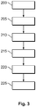
- Figure 3 shows a flow chart of a method for producing the first contact device 15.
- Figure 4 shows a cut-out of a perspective depiction of the first contact device 15 after a second method step 205.
- Figure 5 shows a cut-out of a perspective depiction of the first contact device 15 during a third method step 210.
- the first contact housing 25 is injection-moulded together with a bar 170 arranged at the first housing section 65, by means of a first injection-moulding tool (not depicted).
- the bar 170 is configured as a rectangle and projects over the first housing section 65 at the front end in the x-direction.
- several bars 170 (not depicted in Figure 4 ) are provided which are arranged at the front end offset at the first housing section 65.
- the geometric configuration of each bar 170 is selected identical to one another. A different configuration than shown in Figure 4 is conceivable for the bar 170.
- the side surface 150 of the bar 170 and the first sealing bearing surface 70 are aligned.
- the sealing element 30 is injection-moulded in a second injection-moulding tool.
- a softer material preferably an elastomer, is used to produce the sealing element 30 here.
- the first contact housing 25 and of the sealing element 30 are each removed from the associated injection-moulding tool.
- sealing element 30 and the first contact housing 25 can be jointly produced in a two-component injection-moulding method.
- the sealing element 30 is mounted on the first contact housing 25.
- the first inner peripheral surface 95 of the sealing element 30 is slid both over the side surface 150 of the bar section 135 and over the first sealing bearing surface 70 in the x-direction in the direction of the first sealing supporting surface 80. It is particularly advantageous if the sealing element 30 is slid onto the first housing section 65 to such an extent that the first front end 125 of the sealing element 30 lies against the first sealing supporting surface 80.
- the bar 170 is hot-caulked.
- a warm-caulking device 180 is provided in the third method step 210.
- the warm-caulking device 180 has a heating unit 185 and a pressing tool 190.
- the heating unit 185 can be a laser light source or an infrared light source, for example.
- the heating unit 185 can also be integrated in a pressing tool 190.
- a section 175 of the bar 170 is heated.
- the section 175 is arranged on a side of the bar 170 which faces away from the first housing section 65. It is also possible for the entire bar 170 to be heated.
- a temperature of the first contact housing 25 and where applicable of at least part of the bar section 135 is kept substantially constant, for example at a room temperature.
- the section 175 is heated to a temperature within a temperature range of the material of the bar 170, in which the temperature is lower than a melting temperature of the material of the first contact housing 25 and of the bar 170.
- the temperature is significantly increased compared to room temperature, so that the material is deformable with a lower expenditure of force than at room temperature.
- a fourth method step 215 the pressing tool 190 is placed onto the bar 170.
- the pressing tool 190 presses against the section 175 of the bar 170 such that the section 175 is deformed corresponding to a profile of the pressing tool 190 and configures the retaining section 140.
- the pressing tool 190 can in this case be configured as, for example, a stamp that has on the inside a receptacle which is configured corresponding to a geometric configuration of the retaining section 140, for example as a rectangle as shown in Figure 2 .
- a solidification or at least a partial solidification of the retaining section 140 is awaited.
- a sixth method step 225 the pressing tool 190 is removed from the first contact device 15.
- the sealing element 30 is secured in a form-fitting manner in its position at the first contact housing 25.
- Figure 6 shows a cut-out of a longitudinal section through a first contact device 15 according to a second embodiment.
- first contact device 15 shown in Figures 1 to 5 and the first contact device 15 described in Figure 6 are configured identically.
- the sealing element 30 has a sealing section 300 and an edge section 305.
- the edge section 305 and the sealing section 300 are configured in an integral and material-uniform manner.
- the second sealing lip 110 is arranged at the periphery on the sealing section 300.
- the edge section 305 substantially has a rectangular cross-section and runs parallel to the first sealing bearing surface 70.
- the edge section 305 is arranged on a side facing away from the first sealing supporting surface 80.
- the sealing element 30 has a first cavity 310 in the edge section 305.
- the first cavity 310 is configured in the shape of a groove and extends in the y-direction over the entire width of the edge section 305. In the z-direction, the first cavity 310 is delimited on a portion of the edge section 305.
- the first cavity 310 is open towards the retaining means 130.
- the retaining section 140 of the retaining means 130 engages the first cavity 310.
- twisting of the sealing element 30 around the x-axis with respect to the first contact housing 25 is reliably avoided.
- a required construction space for the fixing of the sealing element 30 is reduced compared to the configuration shown in Figures 1 and 2 .
- the first contact device 15 shown in Figure 6 is produced by means of the method described in Figure 3 .
- the bar 170 has, however, been melted on and pressed with the pressing tool 190 such that no material excess 141 is formed on that side of the first housing section 65 which faces away from the sealing element 30.
- an engagement of the second contact housing 40 in the second cavity 320 is facilitated.
- Figure 7 shows a perspective depiction of a cut-out of the first contact device 15 shown in Figure 6 .
- the first housing section 65 is circumferentially arranged at the periphery and is interrupted by a second cavity 320.
- the second cavity 320 has a rectangular shape.
- the second cavity 320 is aligned in the y-direction with the first cavity 310 of the sealing element 30.
- a profile of the first housing section 65 is interrupted at the front end by the second cavity 320.
- the bar 170 is arranged in the second cavity 320.
- the retaining section 140 engages the first cavity 310 of the sealing element 30 and the second cavity 320.
- the retaining section 140 is arranged laterally spaced apart relative to the respective cavity profile 325, 330 of the cavity 310, 320.
- the retaining section 140 can also rest against the cavity profile 325, 330 of the cavity 310, 320.
- the spaced-apart arrangement arises in that, when the pressing tool 190 is pressed on, the pressing tool 190 dips into the cavity 310, 320 and deforms the retaining section 140. The deformation can, however, also take place such that the cavity profile 325, 330 of the cavities 310, 320 serves as part of the form of the pressing tool 190.
- the required construction space for forming the retaining means 130 is particularly low.
- Figure 8 shows a perspective depiction of the first contact device 15 shown in Figure 6 after the second method step 205.
- the bar 170 projects out of the second cavity 320, but with the bar 170 being arranged spaced apart relative to a cavity profile 325 of the second cavity 320.
- Figure 9 shows a perspective depiction of a first contact device 15 according to a third embodiment.
- the first contact device 15 shown in Figures 9 and 10 is configured identically to the first contact device 15 shown in Figures 6 and 7 .
- the retaining section 140 has a trapeziform cross-section.
- the retaining section 140 is formed in cross-section as a circle segment or in a triangular shape.
- the retaining means 130 has a guide surface 335 on a side facing away from the sealing element 30 in the x-direction.
- the guide surface 335 is arranged obliquely inclined relative to the first sealing bearing surface 70 and the x-axis of the first contact device 15, which corresponds to the plugging direction of the first contact device 15 on the second contact device 20.
- Figure 10 shows a longitudinal section through the contact system 10 with the first contact device 15 shown in Figure 9 .
- the guide surface 335 begins at the front end on the side facing away from the sealing element 30, at a front end 340 of the retaining means 130.
- the front end 340 of the retaining means 130 is arranged perpendicular to the first sealing bearing surface 70.
- the guide surface 335 and the front end 340 of the retaining means 130 are adjacent to one another approximately in the y-direction at the first sealing bearing surface 70 on a side of the retaining means 130 which faces away from the first sealing bearing surface 70.
- the guide surface 335 extends towards the outside and is adjacent to a peripheral side 345 of the retaining means 130.
- the peripheral side 345 is arranged closer to the sealing element 30 than the front end 340 of the retaining means 130.
- the guide surface 335 is arranged at an angle ⁇ to the first sealing bearing surface 70 and/or to the x-axis or plugging direction.
- the angle ⁇ has a value which is in a range from 25° to 75°, in particular in a range from 35° to 60°.
- the second contact housing 40 has a bevel 350 at the front end.
- the bevel 350 is preferably arranged at the same angle ⁇ to the second sealing bearing surface 115 as the guide surface 335.
- the number of components of the contact system 10 can be reduced. Furthermore, the first contact device 15 can be produced particularly quickly, simply and inexpensively and at the same time it is possible to reliably avoid both positioning the sealing element 30 and damaging the sealing element 30. Furthermore, the injection mould for producing the first contact housing 25 is formed particularly simply so that it is possible in particular to dispense with undercuts for fixing the sealing elements 30 in the injection mould, meaning that the production of the injection mould is particularly simple and inexpensive. Furthermore, the assembly is kept particularly simple through the guiding function of the guide surface 335.
Landscapes
- Engineering & Computer Science (AREA)
- Manufacturing & Machinery (AREA)
- Connector Housings Or Holding Contact Members (AREA)
- Gasket Seals (AREA)
Abstract

Description
- The invention relates to a method according to Claim 1, a contact device according to Claim 4 and a contact system according to Claim 14.
- This patent application claims the priority of German
patent application DE 10 2017 118 362.0 filed August 11, 2017 , entitled, VERFAHREN ZUR HERSTELLUNG EINER KONTAKTEINRICHTUNG, KONTAKTEINRICHTUNG UND KONTAKTSYSTEM the disclosure content of which is hereby incorporated by reference in the entirety and for all purposes. - A contact device comprising a contact housing and a sealing element is known, wherein the sealing element is attached to the contact housing at the periphery. The sealing element can be retained on the contact housing by means of a securing ring, for example, so that the sealing element does not slip when a further contact device is put onto or removed from the contact device.
- The problem of the invention is to provide an improved method for producing a contact device, an improved contact device and an improved contact system.
- This problem is solved by means of a method according to Claim 1, by means of a contact device according to Claim 4 and by means of a contact system according to Claim 14. Advantageous embodiments are specified in the dependent claims.
- It has been recognised that an improved method for producing a contact device can be provided wherein a contact housing, a sealing element and a warm-caulking device comprising a pressing tool and a heating unit are provided. A bar is arranged at the contact housing. The sealing element is slid over the bar onto a sealing bearing surface of the contact housing. To form a retaining means, the bar is hot-caulked in such a way that by means of the heating unit at least a section of the bar is heated, wherein the pressing tool is pressed onto the section and the pressing tool moulds the retaining means from the heated section of the bar, wherein the heated section of the bar is cooled. The retaining means secures a position of the sealing element at the contact housing.
- This configuration has the advantage that the number of components of the contact device is reduced. Furthermore this method of production is also suitable for the production of large quantities in an automatic production process. Furthermore, an injection mould for producing the contact housing can be retained particularly simply and inexpensively.
- In a further embodiment, the section is heated to a predefined temperature, wherein the predefined temperature is lower than a melting temperature of the material of the bar and of the contact housing. As a result, this prevents the material from liquefying and draining off.
- In a further embodiment, a temperature of the contact housing is kept substantially constant during the heating of the section. As a result, possible damage to the contact housing while the pressing tool is being placed on is prevented and as a result the supporting of the pressing tool is reliably ensured via the contact housing by the forces introduced into the bar.
- It has been recognised that a contact device able to be produced according to the method described above can be provided in that the contact device comprises a contact housing and a sealing element, wherein the contact housing has a sealing bearing surface arranged at the periphery, wherein the sealing element rests on the sealing bearing surface at the periphery. The contact housing furthermore has a retaining means, wherein the retaining means is configured to prevent the sealing element from being pulled off of the sealing bearing surface through a touching contact of the sealing element at the retaining means. The retaining means is connected at one side to the contact housing. The retaining means projects beyond the sealing bearing surface with a retaining section. The retaining means and the contact housing are configured in an integral and material-uniform manner. As a result, the number of components of the contact device can be kept particularly low.
- In a further embodiment, the retaining means has a bar section, wherein the bar section is connected by a fixed end to the contact housing. A side surface of the bar section and the sealing bearing surface are arranged in alignment. The retaining section is arranged inclined, preferably perpendicular, relative to the bar section. The retaining section is hot-caulked.
- In a further embodiment, the contact housing has a cavity with a cavity profile. The retaining means is arranged in the cavity, spaced apart from the cavity profile. The cavity profile is preferably configured corresponding to the pressing tool. As a result, in the production of the contact device, the pressing tool can dip into the cavity and the contact device can be configured particularly compactly.
- In a further embodiment, the contact device has at least one contact element, wherein the contact housing has a contact section and a housing section. The contact element is arranged in the contact section at least in sections. The housing section is arranged at the periphery circumferentially around the contact section. The sealing bearing surface is arranged at the periphery at the housing section. The housing section is interrupted at the front end by the cavity and the retaining means. As a result, the required construction space for forming the contact housing can be kept particularly small.
- In a further embodiment, the sealing element has a further cavity, wherein the further cavity is arranged on a front end of the sealing element, which front end faces the retaining means. The further cavity is open toward the retaining means, wherein the retaining section engages the further cavity. As a result, the required construction space can be further reduced.
- In a further embodiment, the sealing element has a sealing section and an edge section which is connected to the sealing section, wherein the sealing section has at least one sealing lip at the periphery, wherein the edge section preferably has a rectangular cross-section. The cavity is arranged in the edge section. Through this configuration, a play-free form-fitting connection of the sealing element at the contact housing is ensured and at the same time the required construction space is reduced once again.
- In a further embodiment, the retaining means has a guide surface on a side facing away from the sealing element, wherein the guide surface is arranged obliquely inclined relative to the sealing bearing surface and/or a plugging direction of the contact device at a further contact device. The guide surface is preferably arranged at an angle to the sealing bearing surface and/or the plugging direction, wherein the angle has a value which is in a range from 25° to 75°, in particular in a range from 35° to 60°. As a result, squashing of the sealing element when the contact device and the further contact device are plugged into one another is reliably avoided because the guide surface guides a contact housing of the further contact device towards its correct orientation relative to the contact housing of the contact device.
- In a further embodiment, the guide surface extends between a front end of the retaining means and a peripheral side arranged at the periphery of the retaining means. The peripheral side is arranged closer to the sealing element than the front end. The guide surface begins situated internally at the front end and ends situated externally at the peripheral side.
- In a further embodiment, the retaining section has a trapeziform or rectangular or triangular cross-section.
- In a further embodiment, the sealing bearing surface is arranged at an outer peripheral side of the contact housing, wherein the contact housing has a sealing supporting surface arranged at the front end. The sealing supporting surface is adjacent to the sealing bearing surface and is arranged inclined, preferably perpendicularly, to the sealing bearing surface. The sealing bearing surface is formed circumferentially at the periphery. The sealing element rests on the sealing bearing surface, on the outside. The sealing element is arranged between the retaining means and the sealing supporting surface, preferably without play. As a result, a position of the sealing element is fixed in a form-fitting manner.
- It has been recognised that an improved contact system with a contact device and a further contact device can be provided by the contact device being formed as described above, wherein the further contact device has a further contact housing, wherein the further contact housing has a further sealing bearing surface, wherein the contact device and the further contact device are plugged into one another and delimit an inner space, wherein the sealing element is arranged between the sealing bearing surface and the further sealing bearing surface and seals the inner space off at least in sections from a surrounding area. The retaining means is formed to retain the sealing element in its position on the sealing bearing surface of the contact device when the contact device is pulled away from the further contact device.
- In a further embodiment, when the contact device and the further contact device are plugged into one another, the further contact housing rests against the guide surface of the retaining means, wherein the guide surface is formed to guide the further contact housing transverse to the plugging movement toward the sealing element.
- The invention will be explained in more detail hereafter with reference to figures. In the drawings:
- Figure 1
- shows a perspective depiction of a contact system with a first contact device according to a first embodiment;
- Figure 2
- shows a cut-out of a longitudinal section through the contact system shown in
Figure 1 ; - Figure 3
- shows a flow chart of a method for producing the first contact device which is shown in
Figures 1 and2 ; - Figure 4
- shows a cut-out of a perspective depiction after a second method step;
- Figure 5
- shows a cut-out of a perspective depiction during a third method step;
- Figure 6
- shows a cut-out of a longitudinal section through a first contact device according to a second embodiment;
- Figure 7
- shows a cut-out of a longitudinal section through the first contact device which is shown in
Figure 6 , after a fourth method step; - Figure 8
- shows a cut-out of a perspective depiction of the first contact device which is shown in
Figure 6 , after a second method step; - Figure 9
- shows a cut-out of a longitudinal section through a first contact system according to a third embodiment;
- Figure 10
- shows a cut-out of a longitudinal section through a contact system with the first contact device shown in
Figure 9 ; - In the following figures, reference is made to a coordinate
system 5. The coordinatesystem 5 is configured as a right-handed system and has by way of example an x-axis (longitudinal direction), a y-axis (transverse direction) and a z-axis (vertical direction). The coordinatesystem 5 can also be configured differently. -
Figure 1 shows a perspective depiction of acontact system 10 with a first contact device 15 (depicted using continuous lines) and a second contact device 20 (schematically indicated inFigure 1 by means of dashed lines). - The
first contact device 15 has afirst contact housing 25 with acontact section 26. Thecontact section 26 is depicted on the right inFigure 1 and hasseveral contact receptacles 27 which are arranged in rows and configured like sleeves, wherein onefirst contact element 35 respectively of thefirst contact device 15 is arranged in eachcontact receptacle 27. Thefirst contact element 35 is configured by way of example as a socket contact. - Towards the exterior, the
contact section 26 is delimited by afirst housing section 65. Thefirst housing section 65 has a firstsealing bearing surface 70, wherein a sealingelement 30 of thefirst contact device 15 arranged on the firstsealing bearing surface 70 on the outside. The sealingelement 30 is configured circumferentially around the firstsealing bearing surface 70. Here, the sealingelement 30 has an approximately rectangular cross-section.
When thesecond contact device 20 is in the mounted state on thefirst contact device 15, the sealingelement 30 seals aninner space 50, in which thecontact section 26 is arranged, off from a surroundingarea 55. In this case, the sealingelement 30 is externally encompassed at the periphery side by asecond contact housing 40 of thesecond contact device 20. -
Figure 2 shows a cut-out of a longitudinal section through thecontact system 10 shown inFigure 1 . - The
second contact device 20 has, alongside thesecond contact housing 40, at least onesecond contact element 45. Thesecond contact element 45 is arranged in thesecond contact housing 40. In the embodiment, thesecond contact element 45 is configured by way of example as a pin contact which, when thefirst contact device 15 is in the mounted state on thesecond contact device 20, engages in thefirst contact element 35 and forms an electrical contact between thefirst contact element 35 and thesecond contact element 45. Thesecond contact element 45 can also be configured differently. Therefore it is also conceivable, for example, for thesecond contact element 45 to be configured as a socket contact and thefirst contact element 35 to be configured as a plug contact. - Furthermore, on the rear side (not depicted in
Figure 2 ), thecontact housings inner space 50 is fully sealed off from the surroundingarea 55. Thefirst contact element 35 and thesecond contact element 45 are oriented parallel to the x-axis. In order to plug thefirst contact device 15 and thesecond contact device 20 into one another, a plugging movement is carried out in the longitudinal direction (x-direction). - The
first contact housing 25 has, at anouter periphery side 60, the circumferentially arrangedfirst housing section 65, which extends in a straight line in the x-direction. Thefirst housing section 65, with reference to the x-axis, is configured in a barrel-like manner circumferentially around the x-axis. At the outside, thefirst housing section 65 has the firstsealing bearing surface 70. The firstsealing bearing surface 70 extends parallel to the x-axis. The first contact housing has asecond housing section 75. The second housing section is oriented perpendicular to thefirst housing section 65 and extends in the y-direction over the entire width of thefirst contact housing 25. Thesecond housing section 75 is connected to thefirst housing section 65 and has a firstsealing supporting surface 80 arranged on the front end. In the embodiment, the firstsealing supporting surface 80 is arranged perpendicular to the firstsealing bearing surface 70 and abuts the firstsealing bearing surface 70 at the inside. Outside at the periphery, afirst housing cavity 85 is arranged at the firstsealing bearing surface 70, wherein athird housing section 90 of thesecond contact housing 40 engages in thefirst housing cavity 85. - The sealing
element 30 has, at a firstinner periphery side 95, at least onefirst sealing lip 100, preferably several first sealinglips 100 arranged spaced apart from one another in the x-direction. Thefirst sealing lips 100 bear on the firstsealing bearing surface 70. At an outersecond periphery side 105 of the sealingelement 30, the sealingelement 30 has at least onesecond sealing lip 110, preferably severalsecond sealing lips 110 spaced apart from one another in the x-direction. - The
second contact housing 40 has athird housing section 90. Thethird housing section 90 is arranged on a side facing thefirst contact housing 25 and extends substantially in the x-direction. Thethird housing section 90 has a secondsealing bearing surface 115 at the inside. The secondsealing bearing surface 115 is arranged offset towards the outside relative to the firstsealing bearing surface 70. The firstsealing bearing surface 70 and the secondsealing bearing surface 115 form asealing gap 120, in which the sealingelement 30 is arranged. Thesecond sealing lip 110 bears at the outside on the secondsealing bearing surface 115, so that the sealingelement 30 reliably seals theinner space 50 off from the surroundingarea 55. At the front end, the sealingelement 30 lies against the firstsealing supporting surface 80 with a firstfront end 125, so that, when thesecond contact device 20 is slid onto thefirst contact device 15, frictional forces, which are introduced into the sealingelement 30 when thesecond contact housing 40 is slid on, are supported at the rear side via the firstfront end 125 at the firstsealing supporting surface 80. - The
first contact housing 25 further has a retaining means 130. The retaining means 130 has abar section 135 and aretaining section 140. Thebar section 135 is connected by afixed end 145 to thefirst housing section 65. Thebar section 135 and thefirst housing section 65 are aligned. Thebar section 135 has aside surface 150 at theouter periphery side 60 of thefirst contact housing 25, wherein theside surface 150 of thebar section 135 and the firstsealing bearing surface 70 are oriented in an aligned manner. - In the embodiment, the
bar section 135 has, by way of example, a rectangular cross-section and in the embodiment has the same width as thefirst housing section 65. In addition, at the inside relative to thefirst housing section 65 and thebar section 135, there can be provided asecond housing cavity 136, wherein thesecond contact housing 40, in the mounted state on thefirst contact device 15, can engage in thesecond housing cavity 136. - The retaining
section 140 is arranged on a side facing away from the first housing section 65 (and thus on a side facing the second contact device 20). In the embodiment, the retainingsection 140 is, by way of example, arranged perpendicular to the firstsealing bearing surface 70 and to theside surface 150 of thebar section 135.
In the embodiment, the retainingsection 140 likewise has, by way of example, a rectangular cross-section. In this case, the retainingsection 140 is arranged, at least in sections, on the outside relative to thebar section 135. - The retaining
section 140 has asecond bearing surface 155 on a side facing the sealingelement 30. The secondsealing supporting surface 155 is preferably oriented parallel to the firstsealing supporting surface 80. Furthermore, the firstsealing supporting surface 80 and the secondsealing supporting surface 155 are arranged approximately on the same level in the y-direction. - In the embodiment, the sealing
element 30 is arranged spaced apart from the secondsealing supporting surface 155, so that agap 165 is arranged between a secondfront end 160 of the sealingelement 30, which second front end, in the x-direction, is arranged opposite the firstfront end 125 of the sealingelement 30, and the secondsealing supporting surface 155. The secondfront end 160 of the sealingelement 30 may also lie against the secondsealing supporting surface 155. - The retaining means 130 is configured in an integral and material-uniform manner with the
first contact housing 25. The retaining means 130 is produced by means of hot-caulking, so that typical material alterations prevalent with hot-caulking can be detected compared to thefirst contact housing 25, particularly at theretaining section 140. Thefirst contact housing 25 and the retaining means 130 preferably have a plastic, particularly a thermoplastic plastic, as the material. In addition, as a result of the hot-caulking, there can be provided on the inside of the bar section 135 amaterial excess 141 which projects into thesecond housing cavity 136. - Through the arrangement of the sealing
element 30 between the retaining means 130 and the firstsealing supporting surface 80, a position of the sealingelement 30 at thefirst contact housing 25 is fixed. Here, the sealingelement 30 strikes against the firstsealing supporting surface 80 by the firstfront end 125 of the sealingelement 30 when the twocontact devices first contact device 15 is separated from thesecond contact device 20, the sealingelement 30 can be carried along by thesecond contact housing 40, if thegap 165 is provided, through a friction lock between thesecond sealing lip 110 and the secondsealing bearing surface 115, wherein the attachment of the sealingelement 30 on thefirst contact housing 25 in the x-direction is ensured by the secondfront end 160 of the sealingelement 30 striking against the second sealing supporting surface, and thus an undesired pulling of the sealingelement 30 off of thefirst contact housing 25 is avoided. -
Figure 3 shows a flow chart of a method for producing thefirst contact device 15.Figure 4 shows a cut-out of a perspective depiction of thefirst contact device 15 after asecond method step 205.Figure 5 shows a cut-out of a perspective depiction of thefirst contact device 15 during athird method step 210. - In a
first method step 200, thefirst contact housing 25 is injection-moulded together with abar 170 arranged at thefirst housing section 65, by means of a first injection-moulding tool (not depicted). Thebar 170 is configured as a rectangle and projects over thefirst housing section 65 at the front end in the x-direction. In the embodiment, several bars 170 (not depicted inFigure 4 ) are provided which are arranged at the front end offset at thefirst housing section 65. The geometric configuration of eachbar 170 is selected identical to one another. A different configuration than shown inFigure 4 is conceivable for thebar 170. Theside surface 150 of thebar 170 and the firstsealing bearing surface 70 are aligned. - Furthermore, in the
first method step 200, the sealingelement 30 is injection-moulded in a second injection-moulding tool. A softer material, preferably an elastomer, is used to produce the sealingelement 30 here. - After the materials of the
first contact housing 25 and of the sealingelement 30 have solidified, thefirst contact housing 25 and the sealingelement 30 are each removed from the associated injection-moulding tool. - Alternatively, it is also conceivable for the sealing
element 30 and thefirst contact housing 25 to be jointly produced in a two-component injection-moulding method. - In the
second method step 205, the sealingelement 30 is mounted on thefirst contact housing 25. Here, the first innerperipheral surface 95 of the sealingelement 30 is slid both over theside surface 150 of thebar section 135 and over the firstsealing bearing surface 70 in the x-direction in the direction of the firstsealing supporting surface 80. It is particularly advantageous if the sealingelement 30 is slid onto thefirst housing section 65 to such an extent that the firstfront end 125 of the sealingelement 30 lies against the firstsealing supporting surface 80. - In the following third to fifth method steps 210 to 220, the
bar 170 is hot-caulked. For this purpose, a warm-caulking device 180 is provided in thethird method step 210. The warm-caulking device 180 has aheating unit 185 and apressing tool 190. Theheating unit 185 can be a laser light source or an infrared light source, for example. Theheating unit 185 can also be integrated in apressing tool 190. - In the
third method step 210, asection 175 of thebar 170 is heated. Thesection 175 is arranged on a side of thebar 170 which faces away from thefirst housing section 65. It is also possible for theentire bar 170 to be heated. - During the heating of the
section 175, a temperature of thefirst contact housing 25 and where applicable of at least part of thebar section 135 is kept substantially constant, for example at a room temperature. In this case, thesection 175 is heated to a temperature within a temperature range of the material of thebar 170, in which the temperature is lower than a melting temperature of the material of thefirst contact housing 25 and of thebar 170. However, the temperature is significantly increased compared to room temperature, so that the material is deformable with a lower expenditure of force than at room temperature. - In a
fourth method step 215, thepressing tool 190 is placed onto thebar 170. Thepressing tool 190 presses against thesection 175 of thebar 170 such that thesection 175 is deformed corresponding to a profile of thepressing tool 190 and configures the retainingsection 140. Thepressing tool 190 can in this case be configured as, for example, a stamp that has on the inside a receptacle which is configured corresponding to a geometric configuration of theretaining section 140, for example as a rectangle as shown inFigure 2 . In afifth method step 220, a solidification or at least a partial solidification of theretaining section 140 is awaited. - In a
sixth method step 225, thepressing tool 190 is removed from thefirst contact device 15. Through the formation of theretaining section 140, the sealingelement 30 is secured in a form-fitting manner in its position at thefirst contact housing 25. -
Figure 6 shows a cut-out of a longitudinal section through afirst contact device 15 according to a second embodiment. - Unless otherwise indicated, the
first contact device 15 shown inFigures 1 to 5 and thefirst contact device 15 described inFigure 6 are configured identically. - The sealing
element 30 has asealing section 300 and anedge section 305. Theedge section 305 and thesealing section 300 are configured in an integral and material-uniform manner. Thesecond sealing lip 110 is arranged at the periphery on thesealing section 300. Theedge section 305 substantially has a rectangular cross-section and runs parallel to the firstsealing bearing surface 70. Theedge section 305 is arranged on a side facing away from the firstsealing supporting surface 80. The sealingelement 30 has afirst cavity 310 in theedge section 305. Thefirst cavity 310 is configured in the shape of a groove and extends in the y-direction over the entire width of theedge section 305. In the z-direction, thefirst cavity 310 is delimited on a portion of theedge section 305. In the embodiment, there are provided, by way of example, severalfirst cavities 310 which are arranged offset and spaced apart relative to one another in theedge section 305. - The
first cavity 310 is open towards the retaining means 130. The retainingsection 140 of the retaining means 130 engages thefirst cavity 310. Through the engagement of theretaining section 140 in thefirst cavity 310, twisting of the sealingelement 30 around the x-axis with respect to thefirst contact housing 25 is reliably avoided. Furthermore, in the x-direction, a required construction space for the fixing of the sealingelement 30 is reduced compared to the configuration shown inFigures 1 and2 . - The
first contact device 15 shown inFigure 6 is produced by means of the method described inFigure 3 . In addition, thebar 170 has, however, been melted on and pressed with thepressing tool 190 such that nomaterial excess 141 is formed on that side of thefirst housing section 65 which faces away from the sealingelement 30. As a result, an engagement of thesecond contact housing 40 in thesecond cavity 320 is facilitated. -
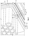
Figure 7 shows a perspective depiction of a cut-out of thefirst contact device 15 shown inFigure 6 . - The
first housing section 65 is circumferentially arranged at the periphery and is interrupted by asecond cavity 320. Thesecond cavity 320 has a rectangular shape. Thesecond cavity 320 is aligned in the y-direction with thefirst cavity 310 of the sealingelement 30. Here, a profile of thefirst housing section 65 is interrupted at the front end by thesecond cavity 320. Thebar 170 is arranged in thesecond cavity 320. - The retaining
section 140 engages thefirst cavity 310 of the sealingelement 30 and thesecond cavity 320. In the embodiment, the retainingsection 140 is arranged laterally spaced apart relative to therespective cavity profile cavity section 140 can also rest against thecavity profile cavity pressing tool 190 is pressed on, thepressing tool 190 dips into thecavity section 140. The deformation can, however, also take place such that thecavity profile cavities pressing tool 190. - By providing the
cavity -
Figure 8 shows a perspective depiction of thefirst contact device 15 shown inFigure 6 after thesecond method step 205. - According to the
second method step 205, thebar 170 projects out of thesecond cavity 320, but with thebar 170 being arranged spaced apart relative to acavity profile 325 of thesecond cavity 320. -
Figure 9 shows a perspective depiction of afirst contact device 15 according to a third embodiment. - Unless otherwise described, the
first contact device 15 shown inFigures 9 and10 is configured identically to thefirst contact device 15 shown inFigures 6 and7 . - In this embodiment, the retaining
section 140 has a trapeziform cross-section. Alternatively, it would also be conceivable that the retainingsection 140 is formed in cross-section as a circle segment or in a triangular shape. - The retaining means 130 has a
guide surface 335 on a side facing away from the sealingelement 30 in the x-direction. Theguide surface 335 is arranged obliquely inclined relative to the firstsealing bearing surface 70 and the x-axis of thefirst contact device 15, which corresponds to the plugging direction of thefirst contact device 15 on thesecond contact device 20. -
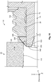
Figure 10 shows a longitudinal section through thecontact system 10 with thefirst contact device 15 shown inFigure 9 . - The
guide surface 335 begins at the front end on the side facing away from the sealingelement 30, at afront end 340 of the retaining means 130. Thefront end 340 of the retaining means 130 is arranged perpendicular to the firstsealing bearing surface 70. Theguide surface 335 and thefront end 340 of the retaining means 130 are adjacent to one another approximately in the y-direction at the firstsealing bearing surface 70 on a side of the retaining means 130 which faces away from the firstsealing bearing surface 70. Theguide surface 335 extends towards the outside and is adjacent to aperipheral side 345 of the retaining means 130. Theperipheral side 345 is arranged closer to the sealingelement 30 than thefront end 340 of the retaining means 130. Theguide surface 335 is arranged at an angle α to the firstsealing bearing surface 70 and/or to the x-axis or plugging direction. The angle α has a value which is in a range from 25° to 75°, in particular in a range from 35° to 60°. - The
second contact housing 40 has abevel 350 at the front end. Thebevel 350 is preferably arranged at the same angle α to the secondsealing bearing surface 115 as theguide surface 335. Through the corresponding arrangement of thebevel 350 and theguide surface 335, it can be assured that, when thefirst contact device 15 and thesecond contact device 20 are plugged into one another, thebevel 350 lies planarly against theguide surface 335 and theguide surface 335 guides thefirst contact housing 25 outwards in the plugging movement in the direction of the sealingelement 30, so that squashing of the sealingelement 30 in thesealing gap 120 is avoided. As a result, a particularly reliable plugging of thefirst contact device 15 and thesecond contact device 20 onto one another can be ensured and at the same time a reliable sealing-off of theinner space 50 by the sealingelement 30 can be ensured. - Through the above-described configurations of the
contact system 10, the number of components of thecontact system 10 can be reduced. Furthermore, thefirst contact device 15 can be produced particularly quickly, simply and inexpensively and at the same time it is possible to reliably avoid both positioning the sealingelement 30 and damaging the sealingelement 30. Furthermore, the injection mould for producing thefirst contact housing 25 is formed particularly simply so that it is possible in particular to dispense with undercuts for fixing the sealingelements 30 in the injection mould, meaning that the production of the injection mould is particularly simple and inexpensive. Furthermore, the assembly is kept particularly simple through the guiding function of theguide surface 335.
Claims (15)
- A method for producing a contact device (15)- wherein a contact housing (25), a sealing element (30) and a warm-caulking device (180) comprising a pressing tool (190) and a heating unit (185) are provided,- wherein a bar (170) is arranged at the contact housing (25),- wherein the sealing element (30) is slid over the bar (170) onto a sealing bearing surface (70) of the contact housing (25),characterised in that- to form a retaining means (130), the bar (170) is hot-caulked in such a way that by means of the heating unit (185) at least a section (175) of the bar (170) is heated,- wherein the pressing tool (190) is pressed onto the section (175) and the pressing tool (190) moulds the retaining means (130) from the heated section (175) of the bar (170),- wherein the heated section (175) of the bar is cooled,- wherein the retaining means (130) secures a position of the sealing element (30) at the contact housing (25) .
- The method according to Claim 1,- wherein the section (175) is heated to a predefined temperature,- wherein the predefined temperature is lower than a melting temperature of a material of the bar (170) and of the contact housing (25).
- The method according to Claim 1 or 2,- wherein a temperature of the contact housing (25) is kept substantially constant during the heating of the section (175).
- A contact device (15), which is able to be produced according to a method according to any one of the preceding claims,- wherein the contact device (15) comprises a contact housing (25) and a sealing element (30),- wherein the contact housing (25) has a sealing bearing surface (70) arranged at the periphery,- wherein the sealing element (30) rests on the sealing bearing surface (70) at the periphery,- wherein the contact housing (25) has a retaining means (130),- wherein the retaining means (130) is configured to prevent the sealing element (30) from being pulled away from the sealing bearing surface (70) through a touching contact of the sealing element (30) at the retaining means (130),characterised in that- the retaining means (130) is connected at one side to the contact housing (25),- wherein the retaining means (130) projects beyond the sealing bearing surface (70) with a retaining section (140),- wherein the retaining means (130) and the contact housing (25) are configured in an integral and material-uniform manner.
- The contact device (15) according to Claim 4,- wherein the contact housing (130) has a bar section (135),- wherein the bar section (135) is connected by a fixed end (145) to the contact housing (25),- wherein the side surface (150) of the bar section (135) and the sealing bearing surface (70) are arranged in alignment,- wherein the retaining section (140) is arranged inclined, preferably perpendicular, to the bar section (135),- wherein the retaining section (140) is hot-caulked.
- The contact device (15) according to Claim 4 or 5,- wherein the contact housing (25) has a cavity (320) with a cavity profile (325),- wherein the retaining means (130) is arranged in the cavity (320), spaced apart from the cavity profile (325),- wherein the cavity profile (325) is preferably configured corresponding to the pressing tool (190).
- The contact device (15) according to Claim 6,- wherein the contact device (15) has at least one contact element (35),- wherein the contact housing (25) has a contact section (26) and a housing section (65),- wherein the contact element (35) is arranged in the contact section (26) at least in sections,- wherein the housing section (65) is circumferentially arranged at the periphery around the contact section (26),- wherein the sealing bearing surface (70) is arranged at the periphery at the housing section (65),- wherein the housing section (65) is interrupted by the cavity (320) and the retaining means (130) at the front end.
- The contact device (15) according to any one of Claims 4 to 7,- wherein the second sealing element (30) has a further cavity (310),- wherein the further cavity (310) is arranged on a front end (160) of the sealing element (30), which front end faces the retaining means (130),- wherein the further cavity (310) is open towards the retaining means (130),- wherein the retaining section (140) engages the further cavity (310).
- The contact device (15) according to Claim 8,- wherein the sealing element (30) has a sealing section (300) and an edge section (305) which is connected to the sealing section (300),- wherein the sealing section (300) has at least one sealing lip (100, 110) at the periphery,- wherein the edge section (305) preferably has a rectangular cross-section,- wherein the cavity (310) is arranged in the edge section (305).
- The contact device (15) according to any one of Claims 4 to 9,- wherein the retaining means (130) has a guide surface (335) on a side facing away from the sealing element (30),- wherein the guide surface (335) is arranged obliquely inclined relative to the sealing bearing surface (70) and/or a plugging direction of the contact device (15) at a further contact device (20),- wherein the guide surface (335) is preferably arranged at an angle (α) to the sealing bearing surface (70) and/or to the plugging direction,- wherein the angle (α) has a value which is in a range from 25° to 75°, in particular in a range from 35° to 60°.
- The contact device (15) according to Claim 10,- wherein the guide surface (335) extends between a front end (340) of the retaining means (130) and a peripheral side (345) arranged at the periphery of the retaining means (130),- wherein the periphery side (345) is arranged closer to the sealing element (30) than to the front side (340),- wherein the guide surface (335) begins situated internally at the front end (340) and ends situated externally at the peripheral side (345).
- The contact device (15) according to any one of Claims 4 to 11,- wherein the retaining section (140) has a trapeziform or rectangular or triangular cross-section.
- The contact device (15) according to any one of Claims 4 to 12,- wherein the sealing bearing surface (70) is arranged at an outer peripheral side (60) of the contact housing (25),- wherein the contact housing (25) has a sealing supporting surface (80) arranged at the front end,- wherein the sealing supporting surface (80) is arranged adjacent to the sealing bearing surface (70) and inclined, preferably perpendicularly, to the sealing bearing surface (70),- wherein the sealing bearing surface (70) is formed circumferentially at the periphery,- wherein the sealing element (30) rests on the sealing supporting surface (70) at the outside,- wherein the sealing element (30) is arranged between the retaining means (130) and the sealing bearing surface (80), preferably in a play-free manner.
- A contact system (10) with a contact device (15) and a further contact device (20),- wherein the contact device (15) is formed according to any one of Claims 4 to 13,- wherein the further contact device (20) has a further contact housing (40),- wherein the further contact housing (40) has a further sealing bearing surface (115),- wherein the contact device (15) and the further contact device (20) are plugged into one another and delimit an inner space (50),- wherein the sealing element (30) is arranged between the sealing bearing surface (70) and the further sealing bearing surface (115) and seals the inner space (50) off at least in sections from a surrounding area (55),- wherein the retaining means (130) is formed to retain the sealing element (30) in its position on the sealing bearing surface (70) of the contact device (15) when the contact device (15) is pulled away from the further contact device (20).
- The contact system (10) according to Claim 14,- wherein, when the contact device (15) and the further contact device (20) are plugged into one another, the further contact housing (40) rests against the guide surface (335) of the retaining means (130),- wherein the guide surface (335) is formed to guide the further contact housing (40) transverse to the plugging movement toward the sealing element (30).
Applications Claiming Priority (1)
| Application Number | Priority Date | Filing Date | Title |
|---|---|---|---|
| DE102017118362.0A DE102017118362B3 (en) | 2017-08-11 | 2017-08-11 | Method for producing a contact device, contact device and contact system |
Publications (2)
| Publication Number | Publication Date |
|---|---|
| EP3442083A1 true EP3442083A1 (en) | 2019-02-13 |
| EP3442083B1 EP3442083B1 (en) | 2020-06-10 |
Family
ID=63259429
Family Applications (1)
| Application Number | Title | Priority Date | Filing Date |
|---|---|---|---|
| EP18188528.6A Active EP3442083B1 (en) | 2017-08-11 | 2018-08-10 | Method for producing a contact device, contact device and contact system |
Country Status (2)
| Country | Link |
|---|---|
| EP (1) | EP3442083B1 (en) |
| DE (1) | DE102017118362B3 (en) |
Cited By (1)
| Publication number | Priority date | Publication date | Assignee | Title |
|---|---|---|---|---|
| US20220412463A1 (en) * | 2021-06-29 | 2022-12-29 | Te Connectivity Germany Gmbh | Seal for an Electrical Connector with Reduced Insertion Force |
Families Citing this family (2)
| Publication number | Priority date | Publication date | Assignee | Title |
|---|---|---|---|---|
| DE102018133190A1 (en) * | 2018-12-20 | 2020-06-25 | Rosenberger Hochfrequenztechnik Gmbh & Co. Kg | Method of manufacturing a connector housing, injection mold and injection molding machine |
| DE102019205592A1 (en) * | 2019-04-17 | 2020-10-22 | BSH Hausgeräte GmbH | Manufacture of connector parts |
Citations (3)
| Publication number | Priority date | Publication date | Assignee | Title |
|---|---|---|---|---|
| US20160172787A1 (en) * | 2013-05-21 | 2016-06-16 | Continental Automotive Gmbh | Contact device for establishing an electric contact between a printed circuit board and an electromotor |
| WO2016193416A1 (en) * | 2015-06-04 | 2016-12-08 | Te Connectivity India Private Limited | Seal for a housing of a plug-type connector and housing for a plug-type connector |
| US9608360B1 (en) * | 2015-11-10 | 2017-03-28 | Yazaki North America, Inc. | Anti-rotation seal for connector assembly |
Family Cites Families (1)
| Publication number | Priority date | Publication date | Assignee | Title |
|---|---|---|---|---|
| US7083471B2 (en) * | 2003-06-18 | 2006-08-01 | Autonetworks Technologies, Ltd. | Connecting structure of connector, shield connector and lever type connector |
-
2017
- 2017-08-11 DE DE102017118362.0A patent/DE102017118362B3/en not_active Expired - Fee Related
-
2018
- 2018-08-10 EP EP18188528.6A patent/EP3442083B1/en active Active
Patent Citations (3)
| Publication number | Priority date | Publication date | Assignee | Title |
|---|---|---|---|---|
| US20160172787A1 (en) * | 2013-05-21 | 2016-06-16 | Continental Automotive Gmbh | Contact device for establishing an electric contact between a printed circuit board and an electromotor |
| WO2016193416A1 (en) * | 2015-06-04 | 2016-12-08 | Te Connectivity India Private Limited | Seal for a housing of a plug-type connector and housing for a plug-type connector |
| US9608360B1 (en) * | 2015-11-10 | 2017-03-28 | Yazaki North America, Inc. | Anti-rotation seal for connector assembly |
Cited By (2)
| Publication number | Priority date | Publication date | Assignee | Title |
|---|---|---|---|---|
| US20220412463A1 (en) * | 2021-06-29 | 2022-12-29 | Te Connectivity Germany Gmbh | Seal for an Electrical Connector with Reduced Insertion Force |
| US12013037B2 (en) * | 2021-06-29 | 2024-06-18 | Te Connectivity Germany Gmbh | Seal for an electrical connector with reduced insertion force |
Also Published As
| Publication number | Publication date |
|---|---|
| DE102017118362B3 (en) | 2018-11-08 |
| EP3442083B1 (en) | 2020-06-10 |
Similar Documents
| Publication | Publication Date | Title |
|---|---|---|
| EP3442083B1 (en) | Method for producing a contact device, contact device and contact system | |
| EP3226535A1 (en) | Image pickup apparatus | |
| EP3173289B1 (en) | Camera bracket with metal wire spring | |
| US20140070454A1 (en) | Die for insert molding and method for insert molding of collar | |
| JP2010179818A5 (en) | ||
| DE102013206443A1 (en) | Sensor housing for automated, mechanical wiring harness assembly | |
| KR101131594B1 (en) | Socket and header for connector and insert molding method therefor | |
| JP2002527264A (en) | Method of making a thermoplastic part with an injection molded elastomer seal | |
| TR201907925T4 (en) | Injection mold component and methods for creating the butterfly glass, guide rail, flywheel, car door and vehicle. | |
| EP3662294A1 (en) | Rotational speed sensor for a vehicle, particularly commercial vehicle, and to a method for the production thereof | |
| EP3249145A1 (en) | Holder and vehicle aperture plate with holder | |
| EP3164282B1 (en) | Glass encapsulation structure and injection molding device | |
| US20150382470A1 (en) | Electronic circuit device and method for manufacturing same | |
| EP4220107A1 (en) | Measuring device and method for producing a measuring device | |
| US20140206270A1 (en) | Slat, method for mounting a slat, injection mold and method for manufacturing a component of a slat | |
| US20160243933A1 (en) | Filling device | |
| JP6324528B2 (en) | Manufacturing method of waterproof control unit | |
| US9056408B2 (en) | Injection molding machine | |
| EP2829375B1 (en) | Injecton interface device | |
| JP6084540B2 (en) | Heat shield rib forming method for cowl louver | |
| KR102228122B1 (en) | Molding apparatus and method of manufacturing resin modling product | |
| JP4376210B2 (en) | Cable support method | |
| US10016917B2 (en) | Method of injecting sealing gel into recess | |
| US20150217492A1 (en) | Method for producing a radiator box or charge air cooler box | |
| KR20100124145A (en) | Apparatus for coupling mold frame of displayer |
Legal Events
| Date | Code | Title | Description |
|---|---|---|---|
| PUAI | Public reference made under article 153(3) epc to a published international application that has entered the european phase |
Free format text: ORIGINAL CODE: 0009012 |
|
| STAA | Information on the status of an ep patent application or granted ep patent |
Free format text: STATUS: THE APPLICATION HAS BEEN PUBLISHED |
|
| AK | Designated contracting states |
Kind code of ref document: A1 Designated state(s): AL AT BE BG CH CY CZ DE DK EE ES FI FR GB GR HR HU IE IS IT LI LT LU LV MC MK MT NL NO PL PT RO RS SE SI SK SM TR |
|
| AX | Request for extension of the european patent |
Extension state: BA ME |
|
| RIC1 | Information provided on ipc code assigned before grant |
Ipc: H01R 13/52 20060101ALI20190111BHEP Ipc: H01R 107/00 20060101ALN20190111BHEP Ipc: H01R 13/74 20060101ALI20190111BHEP Ipc: H01R 43/00 20060101AFI20190111BHEP Ipc: H01R 43/18 20060101ALI20190111BHEP |
|
| STAA | Information on the status of an ep patent application or granted ep patent |
Free format text: STATUS: REQUEST FOR EXAMINATION WAS MADE |
|
| 17P | Request for examination filed |
Effective date: 20190801 |
|
| RBV | Designated contracting states (corrected) |
Designated state(s): AL AT BE BG CH CY CZ DE DK EE ES FI FR GB GR HR HU IE IS IT LI LT LU LV MC MK MT NL NO PL PT RO RS SE SI SK SM TR |
|
| RIC1 | Information provided on ipc code assigned before grant |
Ipc: H01R 13/74 20060101ALI20191211BHEP Ipc: H01R 43/18 20060101ALI20191211BHEP Ipc: H01R 43/00 20060101AFI20191211BHEP Ipc: H01R 13/52 20060101ALI20191211BHEP Ipc: H01R 107/00 20060101ALN20191211BHEP |
|
| GRAP | Despatch of communication of intention to grant a patent |
Free format text: ORIGINAL CODE: EPIDOSNIGR1 |
|
| STAA | Information on the status of an ep patent application or granted ep patent |
Free format text: STATUS: GRANT OF PATENT IS INTENDED |
|
| INTG | Intention to grant announced |
Effective date: 20200120 |
|
| GRAJ | Information related to disapproval of communication of intention to grant by the applicant or resumption of examination proceedings by the epo deleted |
Free format text: ORIGINAL CODE: EPIDOSDIGR1 |
|
| STAA | Information on the status of an ep patent application or granted ep patent |
Free format text: STATUS: REQUEST FOR EXAMINATION WAS MADE |
|
| GRAR | Information related to intention to grant a patent recorded |
Free format text: ORIGINAL CODE: EPIDOSNIGR71 |
|
| GRAS | Grant fee paid |
Free format text: ORIGINAL CODE: EPIDOSNIGR3 |
|
| STAA | Information on the status of an ep patent application or granted ep patent |
Free format text: STATUS: GRANT OF PATENT IS INTENDED |
|
| INTC | Intention to grant announced (deleted) | ||
| RIC1 | Information provided on ipc code assigned before grant |
Ipc: H01R 107/00 20060101ALN20200401BHEP Ipc: H01R 43/00 20060101AFI20200401BHEP Ipc: H01R 43/18 20060101ALI20200401BHEP Ipc: H01R 13/74 20060101ALI20200401BHEP Ipc: H01R 13/52 20060101ALI20200401BHEP |
|
| GRAA | (expected) grant |
Free format text: ORIGINAL CODE: 0009210 |
|
| STAA | Information on the status of an ep patent application or granted ep patent |
Free format text: STATUS: THE PATENT HAS BEEN GRANTED |
|
| INTG | Intention to grant announced |
Effective date: 20200422 |
|
| AK | Designated contracting states |
Kind code of ref document: B1 Designated state(s): AL AT BE BG CH CY CZ DE DK EE ES FI FR GB GR HR HU IE IS IT LI LT LU LV MC MK MT NL NO PL PT RO RS SE SI SK SM TR |
|
| REG | Reference to a national code |
Ref country code: GB Ref legal event code: FG4D |
|
| REG | Reference to a national code |
Ref country code: CH Ref legal event code: EP Ref country code: AT Ref legal event code: REF Ref document number: 1279919 Country of ref document: AT Kind code of ref document: T Effective date: 20200615 |
|
| REG | Reference to a national code |
Ref country code: DE Ref legal event code: R096 Ref document number: 602018005170 Country of ref document: DE |
|
| REG | Reference to a national code |
Ref country code: IE Ref legal event code: FG4D |
|
| REG | Reference to a national code |
Ref country code: LT Ref legal event code: MG4D |
|
| PG25 | Lapsed in a contracting state [announced via postgrant information from national office to epo] |
Ref country code: SE Free format text: LAPSE BECAUSE OF FAILURE TO SUBMIT A TRANSLATION OF THE DESCRIPTION OR TO PAY THE FEE WITHIN THE PRESCRIBED TIME-LIMIT Effective date: 20200610 Ref country code: NO Free format text: LAPSE BECAUSE OF FAILURE TO SUBMIT A TRANSLATION OF THE DESCRIPTION OR TO PAY THE FEE WITHIN THE PRESCRIBED TIME-LIMIT Effective date: 20200910 Ref country code: GR Free format text: LAPSE BECAUSE OF FAILURE TO SUBMIT A TRANSLATION OF THE DESCRIPTION OR TO PAY THE FEE WITHIN THE PRESCRIBED TIME-LIMIT Effective date: 20200911 Ref country code: FI Free format text: LAPSE BECAUSE OF FAILURE TO SUBMIT A TRANSLATION OF THE DESCRIPTION OR TO PAY THE FEE WITHIN THE PRESCRIBED TIME-LIMIT Effective date: 20200610 Ref country code: LT Free format text: LAPSE BECAUSE OF FAILURE TO SUBMIT A TRANSLATION OF THE DESCRIPTION OR TO PAY THE FEE WITHIN THE PRESCRIBED TIME-LIMIT Effective date: 20200610 |
|
| REG | Reference to a national code |
Ref country code: NL Ref legal event code: MP Effective date: 20200610 |
|
| PG25 | Lapsed in a contracting state [announced via postgrant information from national office to epo] |
Ref country code: HR Free format text: LAPSE BECAUSE OF FAILURE TO SUBMIT A TRANSLATION OF THE DESCRIPTION OR TO PAY THE FEE WITHIN THE PRESCRIBED TIME-LIMIT Effective date: 20200610 Ref country code: RS Free format text: LAPSE BECAUSE OF FAILURE TO SUBMIT A TRANSLATION OF THE DESCRIPTION OR TO PAY THE FEE WITHIN THE PRESCRIBED TIME-LIMIT Effective date: 20200610 Ref country code: LV Free format text: LAPSE BECAUSE OF FAILURE TO SUBMIT A TRANSLATION OF THE DESCRIPTION OR TO PAY THE FEE WITHIN THE PRESCRIBED TIME-LIMIT Effective date: 20200610 Ref country code: BG Free format text: LAPSE BECAUSE OF FAILURE TO SUBMIT A TRANSLATION OF THE DESCRIPTION OR TO PAY THE FEE WITHIN THE PRESCRIBED TIME-LIMIT Effective date: 20200910 |
|
| REG | Reference to a national code |
Ref country code: AT Ref legal event code: MK05 Ref document number: 1279919 Country of ref document: AT Kind code of ref document: T Effective date: 20200610 |
|
| PG25 | Lapsed in a contracting state [announced via postgrant information from national office to epo] |
Ref country code: NL Free format text: LAPSE BECAUSE OF FAILURE TO SUBMIT A TRANSLATION OF THE DESCRIPTION OR TO PAY THE FEE WITHIN THE PRESCRIBED TIME-LIMIT Effective date: 20200610 Ref country code: AL Free format text: LAPSE BECAUSE OF FAILURE TO SUBMIT A TRANSLATION OF THE DESCRIPTION OR TO PAY THE FEE WITHIN THE PRESCRIBED TIME-LIMIT Effective date: 20200610 |
|
| PG25 | Lapsed in a contracting state [announced via postgrant information from national office to epo] |
Ref country code: RO Free format text: LAPSE BECAUSE OF FAILURE TO SUBMIT A TRANSLATION OF THE DESCRIPTION OR TO PAY THE FEE WITHIN THE PRESCRIBED TIME-LIMIT Effective date: 20200610 Ref country code: AT Free format text: LAPSE BECAUSE OF FAILURE TO SUBMIT A TRANSLATION OF THE DESCRIPTION OR TO PAY THE FEE WITHIN THE PRESCRIBED TIME-LIMIT Effective date: 20200610 Ref country code: PT Free format text: LAPSE BECAUSE OF FAILURE TO SUBMIT A TRANSLATION OF THE DESCRIPTION OR TO PAY THE FEE WITHIN THE PRESCRIBED TIME-LIMIT Effective date: 20201012 Ref country code: EE Free format text: LAPSE BECAUSE OF FAILURE TO SUBMIT A TRANSLATION OF THE DESCRIPTION OR TO PAY THE FEE WITHIN THE PRESCRIBED TIME-LIMIT Effective date: 20200610 Ref country code: SM Free format text: LAPSE BECAUSE OF FAILURE TO SUBMIT A TRANSLATION OF THE DESCRIPTION OR TO PAY THE FEE WITHIN THE PRESCRIBED TIME-LIMIT Effective date: 20200610 Ref country code: ES Free format text: LAPSE BECAUSE OF FAILURE TO SUBMIT A TRANSLATION OF THE DESCRIPTION OR TO PAY THE FEE WITHIN THE PRESCRIBED TIME-LIMIT Effective date: 20200610 Ref country code: CZ Free format text: LAPSE BECAUSE OF FAILURE TO SUBMIT A TRANSLATION OF THE DESCRIPTION OR TO PAY THE FEE WITHIN THE PRESCRIBED TIME-LIMIT Effective date: 20200610 |
|
| PG25 | Lapsed in a contracting state [announced via postgrant information from national office to epo] |
Ref country code: SK Free format text: LAPSE BECAUSE OF FAILURE TO SUBMIT A TRANSLATION OF THE DESCRIPTION OR TO PAY THE FEE WITHIN THE PRESCRIBED TIME-LIMIT Effective date: 20200610 Ref country code: PL Free format text: LAPSE BECAUSE OF FAILURE TO SUBMIT A TRANSLATION OF THE DESCRIPTION OR TO PAY THE FEE WITHIN THE PRESCRIBED TIME-LIMIT Effective date: 20200610 Ref country code: IS Free format text: LAPSE BECAUSE OF FAILURE TO SUBMIT A TRANSLATION OF THE DESCRIPTION OR TO PAY THE FEE WITHIN THE PRESCRIBED TIME-LIMIT Effective date: 20201010 |
|
| REG | Reference to a national code |
Ref country code: DE Ref legal event code: R097 Ref document number: 602018005170 Country of ref document: DE |
|
| PG25 | Lapsed in a contracting state [announced via postgrant information from national office to epo] |
Ref country code: MC Free format text: LAPSE BECAUSE OF FAILURE TO SUBMIT A TRANSLATION OF THE DESCRIPTION OR TO PAY THE FEE WITHIN THE PRESCRIBED TIME-LIMIT Effective date: 20200610 |
|
| PLBE | No opposition filed within time limit |
Free format text: ORIGINAL CODE: 0009261 |
|
| STAA | Information on the status of an ep patent application or granted ep patent |
Free format text: STATUS: NO OPPOSITION FILED WITHIN TIME LIMIT |
|
| PG25 | Lapsed in a contracting state [announced via postgrant information from national office to epo] |
Ref country code: LU Free format text: LAPSE BECAUSE OF NON-PAYMENT OF DUE FEES Effective date: 20200810 Ref country code: DK Free format text: LAPSE BECAUSE OF FAILURE TO SUBMIT A TRANSLATION OF THE DESCRIPTION OR TO PAY THE FEE WITHIN THE PRESCRIBED TIME-LIMIT Effective date: 20200610 |
|
| 26N | No opposition filed |
Effective date: 20210311 |
|
| REG | Reference to a national code |
Ref country code: BE Ref legal event code: MM Effective date: 20200831 |
|
| PG25 | Lapsed in a contracting state [announced via postgrant information from national office to epo] |
Ref country code: SI Free format text: LAPSE BECAUSE OF FAILURE TO SUBMIT A TRANSLATION OF THE DESCRIPTION OR TO PAY THE FEE WITHIN THE PRESCRIBED TIME-LIMIT Effective date: 20200610 |
|
| PG25 | Lapsed in a contracting state [announced via postgrant information from national office to epo] |
Ref country code: IE Free format text: LAPSE BECAUSE OF NON-PAYMENT OF DUE FEES Effective date: 20200810 Ref country code: BE Free format text: LAPSE BECAUSE OF NON-PAYMENT OF DUE FEES Effective date: 20200831 |
|
| REG | Reference to a national code |
Ref country code: CH Ref legal event code: PL |
|
| PG25 | Lapsed in a contracting state [announced via postgrant information from national office to epo] |
Ref country code: LI Free format text: LAPSE BECAUSE OF NON-PAYMENT OF DUE FEES Effective date: 20210831 Ref country code: CH Free format text: LAPSE BECAUSE OF NON-PAYMENT OF DUE FEES Effective date: 20210831 |
|
| PG25 | Lapsed in a contracting state [announced via postgrant information from national office to epo] |
Ref country code: TR Free format text: LAPSE BECAUSE OF FAILURE TO SUBMIT A TRANSLATION OF THE DESCRIPTION OR TO PAY THE FEE WITHIN THE PRESCRIBED TIME-LIMIT Effective date: 20200610 Ref country code: MT Free format text: LAPSE BECAUSE OF FAILURE TO SUBMIT A TRANSLATION OF THE DESCRIPTION OR TO PAY THE FEE WITHIN THE PRESCRIBED TIME-LIMIT Effective date: 20200610 Ref country code: CY Free format text: LAPSE BECAUSE OF FAILURE TO SUBMIT A TRANSLATION OF THE DESCRIPTION OR TO PAY THE FEE WITHIN THE PRESCRIBED TIME-LIMIT Effective date: 20200610 |
|
| PG25 | Lapsed in a contracting state [announced via postgrant information from national office to epo] |
Ref country code: MK Free format text: LAPSE BECAUSE OF FAILURE TO SUBMIT A TRANSLATION OF THE DESCRIPTION OR TO PAY THE FEE WITHIN THE PRESCRIBED TIME-LIMIT Effective date: 20200610 |
|
| GBPC | Gb: european patent ceased through non-payment of renewal fee |
Effective date: 20220810 |
|
| PG25 | Lapsed in a contracting state [announced via postgrant information from national office to epo] |
Ref country code: GB Free format text: LAPSE BECAUSE OF NON-PAYMENT OF DUE FEES Effective date: 20220810 |
|
| PGFP | Annual fee paid to national office [announced via postgrant information from national office to epo] |
Ref country code: FR Payment date: 20250610 Year of fee payment: 8 |
|
| PGFP | Annual fee paid to national office [announced via postgrant information from national office to epo] |
Ref country code: DE Payment date: 20250618 Year of fee payment: 8 |
|
| PGFP | Annual fee paid to national office [announced via postgrant information from national office to epo] |
Ref country code: IT Payment date: 20250722 Year of fee payment: 8 |