EP3442079B1 - Resonant element for frequency selective plate, frequency selective plate and antenna device - Google Patents
Resonant element for frequency selective plate, frequency selective plate and antenna device Download PDFInfo
- Publication number
- EP3442079B1 EP3442079B1 EP16897942.5A EP16897942A EP3442079B1 EP 3442079 B1 EP3442079 B1 EP 3442079B1 EP 16897942 A EP16897942 A EP 16897942A EP 3442079 B1 EP3442079 B1 EP 3442079B1
- Authority
- EP
- European Patent Office
- Prior art keywords
- frequency selective
- selective surface
- radio wave
- poles
- line segment
- Prior art date
- Legal status (The legal status is an assumption and is not a legal conclusion. Google has not performed a legal analysis and makes no representation as to the accuracy of the status listed.)
- Not-in-force
Links
Images




Classifications
-
- H—ELECTRICITY
- H01—ELECTRIC ELEMENTS
- H01Q—ANTENNAS, i.e. RADIO AERIALS
- H01Q15/00—Devices for reflection, refraction, diffraction or polarisation of waves radiated from an antenna, e.g. quasi-optical devices
- H01Q15/14—Reflecting surfaces; Equivalent structures
- H01Q15/16—Reflecting surfaces; Equivalent structures curved in two dimensions [2D], e.g. paraboloidal
- H01Q15/165—Reflecting surfaces; Equivalent structures curved in two dimensions [2D], e.g. paraboloidal composed of a plurality of rigid panels
- H01Q15/167—Reflecting surfaces; Equivalent structures curved in two dimensions [2D], e.g. paraboloidal composed of a plurality of rigid panels comprising a gap between adjacent panels or group of panels, e.g. stepped reflectors
-
- H—ELECTRICITY
- H01—ELECTRIC ELEMENTS
- H01Q—ANTENNAS, i.e. RADIO AERIALS
- H01Q15/00—Devices for reflection, refraction, diffraction or polarisation of waves radiated from an antenna, e.g. quasi-optical devices
- H01Q15/0006—Devices acting selectively as reflecting surface, as diffracting or as refracting device, e.g. frequency filtering or angular spatial filtering devices
- H01Q15/0013—Devices acting selectively as reflecting surface, as diffracting or as refracting device, e.g. frequency filtering or angular spatial filtering devices said selective devices working as frequency-selective reflecting surfaces, e.g. FSS, dichroic plates, surfaces being partly transmissive and reflective
-
- H—ELECTRICITY
- H01—ELECTRIC ELEMENTS
- H01Q—ANTENNAS, i.e. RADIO AERIALS
- H01Q15/00—Devices for reflection, refraction, diffraction or polarisation of waves radiated from an antenna, e.g. quasi-optical devices
- H01Q15/02—Refracting or diffracting devices, e.g. lens, prism
-
- H—ELECTRICITY
- H01—ELECTRIC ELEMENTS
- H01Q—ANTENNAS, i.e. RADIO AERIALS
- H01Q15/00—Devices for reflection, refraction, diffraction or polarisation of waves radiated from an antenna, e.g. quasi-optical devices
- H01Q15/14—Reflecting surfaces; Equivalent structures
-
- H—ELECTRICITY
- H01—ELECTRIC ELEMENTS
- H01Q—ANTENNAS, i.e. RADIO AERIALS
- H01Q15/00—Devices for reflection, refraction, diffraction or polarisation of waves radiated from an antenna, e.g. quasi-optical devices
- H01Q15/14—Reflecting surfaces; Equivalent structures
- H01Q15/147—Reflecting surfaces; Equivalent structures provided with means for controlling or monitoring the shape of the reflecting surface
Definitions
- the present invention relates to a frequency selective surface used as a spatial filter, a resonant element used for the frequency selective surface, and an antenna device mounting the frequency selective surface.
- a frequency selective surface is used as, for example, a spatial filter such as a band-pass filter for transmitting only a radio wave having a desired frequency out of incoming radio waves, or a band-stop filter for reflecting only a radio wave of a desired frequency.
- a spatial filter such as a band-pass filter for transmitting only a radio wave having a desired frequency out of incoming radio waves, or a band-stop filter for reflecting only a radio wave of a desired frequency.
- the frequency selective surface may be applied to, for example, a multifrequency common reflector antenna, a communication system, a radar system, and the like, for applications such as radio wave interference prevention.
- the frequency selective surface is mainly classified into a patch-type frequency selective surface and a hole-type frequency selective surface.
- the patch-type frequency selective surface has structure where a plurality of resonant elements, each being made of metal, is periodically arranged.
- the hole-type frequency selective surface is made of a metal plate having a plurality of holes periodically provided. Each of the holes serves as a resonant element.
- Non-Patent Literature 1 discloses a resonant element in which the roots of three poles are connected to the central part and the extending directions of the tips of the three poles are shifted by 120° from each other.
- Each of the three poles of the resonant element have a rectangular shape.
- Non-Patent Literature 2 discloses a frequency selective surface with fractal resonant elements comprising 4 poles, wherein the roots of the poles are connected to a central part, and wherein the poles are tapered to form pointed tips.
- Patent Literature 1 discloses a frequency selective surface comprising three poles, and wherein the poles are tapered towards the roots.
- Patent Literature 1 JP2000196288 A, 2000 .
- the incident direction of a radio wave to the frequency selective surface is not necessarily the front direction to the frequency selective surface, and an angle of incidence of the radio wave to the frequency selective surface may become large.
- the incidence angle of the radio wave is 0°, whereas the incidence angle becomes larger than 0° as the incident direction shifts from the front direction.
- An index for evaluating the characteristic of the frequency selective surface may be an incidence angle characteristic. It is desirable that a frequency selective surface is capable of obtaining a transmission characteristic and reflection characteristic over broadband even when the incidence angle of the radio wave becomes large.
- the pole length is constant because the resonance frequency of the resonant element may change when the pole length is changed.
- An object of the present invention is to obtain a resonant element of a frequency selective surface, the resonant element being able to be arranged close to other resonant elements within a range not contacting other resonant elements.
- an object of the present invention is to obtain a frequency selective surface capable of obtaining the transmission characteristic and the reflection characteristic over broadband even when the incidence angle of the radio wave becomes large.
- an object of the present invention is to obtain an antenna device mounting the frequency selective surface capable of obtaining the transmission characteristic and the reflection characteristic over broadband even when the incidence angle of the radio wave becomes large.
- a resonant element of a frequency selective surface includes: a plurality of poles whose roots are connected to a central part and wherein the poles extend in mutually different directions on an identical plane or on an identical curved surface to define tips at the distal ends thereof, wherein a pole width at each of the roots is narrower than a pole width between each of the roots and the corresponding one of the tips, a pole width at each of the tips is narrower than the pole width at any position between each of the roots and the corresponding one of the tips, each pole width being defined by a length of a line segment that is perpendicular, on the identical plane or on the identical curved surface, to a line segment connecting the centre of each of the roots to the centre of a corresponding one of the tips in the respective poles, such that the pole widths at the roots of the poles are constricted, the poles are tapered towards the tips, and the pole widths are wider at the middle parts of the poles in comparison to those of the roots and the tips.
- a pole width at each of the roots is narrower than a pole width between each of the roots and the corresponding one of the tips, each pole width being defined by a length of a line segment in a direction perpendicular, on the identical plane or on the identical curved surface, to a line segment connecting each of the roots to a corresponding one of the tips in the respective poles. Therefore, there is an effect that the resonant element can be arranged close to other resonant elements within the range not contacting other resonant elements.
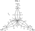
- FIG. 1 is a structural diagram of a resonant element of a frequency selective surface according to the Embodiment 1 of the present invention
- FIG. 2 is a structural diagram of the frequency selective surface according to the Embodiment 1 of the present invention.
- the frequency selective surface is a hole-type frequency selective surface.
- the hole-type frequency selective surface is made of a metal plate 2 having a plurality of holes periodically applied thereto.
- the holes provided in the metal plate 2 serve as resonant elements.
- the holes applied in the metal plate 2 are the resonant elements.
- each hole in the hole-type frequency selective surface coincides with the shape of the resonant element 1 of FIG. 1 .
- central axes 1a, 1b, and 1c are axes of the resonant element 1 arranged at an interval of 120°.
- a central part 10 is a part that is positioned at the center of the resonant element 1.
- the shape of the central part 10 is a triangle.
- the three central axes 1a, 1b, and 1c cross each other at the central point of the central part 10.
- a direction from the central part 10 to the upper side of the sheet is represented as 0°
- a direction to the lower left side of the sheet is represented as 120°
- a direction to the lower right side of the sheet is represented as 240°.
- a to U are signs indicating positions of respective points on the resonant element 1.
- the metal plate 2 is a flat plate having a flat surface.
- the holes, each being the resonant element 1 of FIG. 1 are periodically arranged.
- An arrangement pattern of the resonant elements 1 is formed such that, as illustrated in FIG. 2 , when attention is paid to two resonant elements 1 arranged at adjacent positions among the plurality of resonant elements 1, the tip of one of the poles in one of the two resonant elements 1 is close to the central part 10 of another one of the two resonant elements 1 within a range not contacting another one of the two resonant elements 1.
- a root 11a is connected to the central part 10, and a tip 11b extends in the direction of 0°.
- the pole 11 is arranged on the central axis 1a and has a line-symmetrical shape with the central axis 1a as the axis of symmetry.
- a root 12a is connected to the central part 10, and a tip 12b extends in the direction of 120°.
- the pole 12 is arranged on the central axis 1b and has a line-symmetrical shape with the central axis 1b as the axis of symmetry.
- a root 13a is connected to the central part 10, and a tip 13b extends in the direction of 240°.
- the pole 13 is arranged on the central axis 1c and has a line-symmetrical shape with the central axis 1c as the axis of symmetry.
- the metal plate 2 is a flat plate
- the tips 11b, 12b, and 13b of the respective poles 11, 12, and 13 extend in mutually different directions on the identical plane. Specifically, the extending directions of the tips 11b, 12b, and 13b of the respective poles 11, 12, and 13 are shifted by 120° from each other.
- the resonant element 1 includes the three poles 11, 12, and 13. Alternatively, the resonant element 1 may include four or more poles.
- the resonant element 1 When the resonant element 1 includes, for example, four poles, the resonant element 1 has a shape in which the extending directions of the tips of the four poles are shifted by 90° from each other. As another example, when the resonant element 1 includes five poles, the resonant element 1 has a shape in which the extending directions of the tips of the five poles are shifted by 72° from each other.
- the pole width at the root 11a is narrower than the pole width between the root 11a and the tip 11b.
- the pole width is the length of the line segment in a direction perpendicular, on the identical plane, to the line segment connecting the root 11a to the tip 11b in the pole 11.
- the pole width at the tip 11b is narrower than the pole width between the root 11a and the tip 11b.
- line segment RS a line segment connecting a point R to a point S
- line segment RS corresponds to a line segment connecting the root 11a to the tip 11b in the pole 11.
- a line segment connecting a point A to a point Q (hereinafter referred to as "line segment AQ”), a line segment connecting a point C to a point O (hereinafter referred to as “line segment CO”), and a line segment connecting a point B to a point P (hereinafter referred to as “line segment BP”) each correspond to a line segment in a direction perpendicular to the line segment RS.
- the length of the line segment CO corresponds to the pole width at the root 11a
- the length of the line segment AQ corresponds to the pole width at the tip 11b
- the length of the line segment BP corresponds to the pole width between the root 11a and the tip 11b.
- the length of the line segment BP is referred to as the pole width of the middle part of the pole 11.
- the length of the line segment CO and the length of the line segment AQ are shorter than the length of the line segment BP.
- the pole width at the root 12a is narrower than the pole width between the root 12a and the tip 12b.
- the pole width is the length of the line segment in a direction perpendicular, on the identical plane, to the line segment connecting the root 12a to the tip 12b in the pole 12.
- the pole width at the tip 12b is narrower than the pole width between the root 12a and the tip 12b.
- line segment FT a line segment connecting a point F to a point T
- line segment FT corresponds to a line segment connecting the root 12a to the tip 12b in the pole 12.
- a line segment connecting a point E to a point G (hereinafter referred to as "line segment EG"), a line segment connecting the point C to a point I (hereinafter referred to as “line segment CI”), and a line segment connecting a point D to a point H (hereinafter referred to as “line segment DH”) each correspond to a line segment in a direction perpendicular to the line segment FT.
- the length of the line segment CI corresponds to the pole width at the root 12a
- the length of the line segment EG corresponds to the pole width at the tip 12b
- the length of the line segment DH corresponds to the pole width between the root 12a and the tip 12b.
- the length of the line segment DH is referred to as the pole width of the middle part of the pole 12.
- the length of the line segment CI and the length of the line segment EG are shorter than the length of the line segment DH.
- the pole width at the root 13a is narrower than the pole width between the root 13a and the tip 13b.
- the pole width is the length of the line segment in a direction perpendicular, on the identical plane, to the line segment connecting the root 13a to the tip 13b in the pole 13.
- the pole width at the tip 13b is narrower than the pole width between the root 13a and the tip 13b.
- line segment LU a line segment connecting a point L to a point U (hereinafter referred to as "line segment LU") corresponds to a line segment connecting the root 13a to the tip 13b in the pole 13.
- a line segment connecting a point K to a point M (hereinafter referred to as “line segment KM”), a line segment connecting the point I to the point O (hereinafter referred to as “line segment IO”), and a line segment connecting a point J to a point N (hereinafter referred to as “line segment JN”) each correspond to a line segment in a direction perpendicular to the line segment LU.
- the length of the line segment IO corresponds to the pole width at the root 13a
- the length of the line segment KM corresponds to the pole width at the tip 13b
- the length of the line segment JN corresponds to the pole width between the root 13a and the tip 13b.
- the length of the line segment JN is referred to as the pole width of the middle part of the pole 13.
- the length of the line segment IO and the length of the line segment KM are shorter than the length of the line segment JN.
- the pole width at each of the root 11a, 12a, and 13a is narrower than the pole width at the corresponding middle part.
- the pole width at each of the tips 11b, 12b, and 13b is narrower than the pole width at the corresponding middle part.
- the resonant element 1 has a wedge shape in which the central part 10 is constricted, and the tips 11b, 12b, and 13b of the respective poles 11, 12, and 13 are tapered.
- pole width of the middle part is widened, even when the pole widths at the root 11a, 12a, and 13a and the pole widths at the tip 11b, 12b, and 13b are narrow, a large area can be secured in the entire poles 11, 12, and 13.
- the incident radio wave has a reflection coefficient of "-1" and a transmission coefficient of "0".
- the reflection coefficient of "-1” means that all the incident radio waves are reflected, and the transmission coefficient of "0" means that there is no radio wave to be transmitted.
- the magnitude of the scattered wave propagated depends on the magnitude of the magnetic current induced in the resonant element 1.
- a scattering coefficient thereof is "1".
- the scattering coefficient "1" means a radio wave of the same magnitude in the direction opposite to the reflected wave of the incident radio wave.
- the radio wave incident on the hole-type frequency selective surface is transmitted with a transmission coefficient of "1".
- the transmission coefficient "1" means that all the incident radio waves are transmitted.
- the hole-type frequency selective surface operates as a band-pass filter whose transmission coefficient is "1".
- the plurality of resonant elements 1 is arranged with an arrangement pattern called a triangular arrangement.
- the resonant element 1 is arranged at each vertex of an equilateral triangle, and equilateral triangles, each including the resonant element 1 arranged at each vertex, are periodically arranged.
- the equilateral triangle is highlighted by a broken line, and a plurality of the equilateral triangles is arranged to be mingled with each other.
- FIG. 2 for simplicity of the drawing, only four equilateral triangles are highlighted by broken lines.
- the tip of the pole in the specific resonant element 1 is arranged near a constricted portion in the central part 10 of an adjacent resonant element 1.
- the shape of the central part 10 of the resonant element 1 of the Embodiment 1 is a wedge shape having the constricted portion.
- the tip of the pole can be brought close to the central part 10 of the adjacent resonant element 1 by an amount corresponding to the constricted portion without contacting the adjacent resonant element 1.
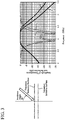
- FIG. 3 is an explanatory diagram of the transmission characteristic and the reflection characteristic of the hole-type frequency selective surface.
- FIG. 3 a two-layer structure is illustrated, in which two frequency selective surfaces shown in FIG. 2 are stacked as the hole-type frequency selective surface of the Embodiment 1.
- the transmission characteristic and the reflection characteristic are illustrated with an assumption that the incidence angle of the radio wave is 40°.
- FIG. 3 for comparing with the hole-type frequency selective surface of the Embodiment 1, the transmission characteristic and the reflection characteristic of a hole-type frequency selective surface are also illustrated, in which holes as resonant elements are formed by rectangular poles and are periodically provided (hereinafter referred to as "a conventional hole-type frequency selective surface").
- the conventional hole-type frequency selective surface is dimensionally optimized such that the transmission characteristic and the reflection characteristic at the incidence angle of 0° are the same as those of the hole-type frequency selective surface of the Embodiment 1.
- the conventional hole-type frequency selective surface is assumed to have a two-layer structure, and the transmission characteristic and the reflection characteristic are illustrated with an assumption that the incidence angle of the radio wave is 40°.
- X 1 indicates the transmission characteristic of the hole-type frequency selective surface of the Embodiment 1
- X 2 indicates the reflection characteristic of the hole-type frequency selective surface of the Embodiment 1.
- Y 1 indicates the transmission characteristic of the conventional hole-type frequency selective surface
- Y 2 indicates the reflection characteristic of the conventional hole-type frequency selective surface
- the transmission characteristic X 1 of the hole-type frequency selective surface of the Embodiment 1 is approximately the same as the transmission characteristic Y 1 of the conventional hole-type frequency selective surface.
- the transmission loss of the hole-type frequency selective surface of the Embodiment 1 is smaller than the transmission loss of the conventional hole-type frequency selective surface.
- the transmission loss of the hole-type frequency selective surface of the Embodiment 1 is about -22 dB, whereas the transmission loss of the conventional hole-type frequency selective surface is about -30 dB.
- the reflection loss of the hole-type frequency selective surface of the Embodiment 1 is slightly smaller than the reflection loss of the conventional hole-type frequency selective surface.
- the reflection loss of the hole-type frequency selective surface of the Embodiment 1 is considerably larger than the reflection loss of the conventional hole-type frequency selective surface.
- FIG. 3 illustrates the example of the two-layer structure in which two hole-type frequency selective surfaces are stacked, even in the case of a multilayer structure in which three or more hole-type frequency selective surfaces are stacked to be used, or in the case of a single layer structure in which only one hole-type frequency selective surface is used, the transmission characteristic and the reflection characteristic over broadband can be obtained, as in the case of the two-layer structure.
- the poles 11, 12, and 13 whose roots 11a, 12a, and 13a are connected to the central part 10 and whose tips 11b, 12b, and 13b extend in mutually different directions on an identical plane or on an identical curved surface.
- a pole width at each of the roots 11a, 12a, and 13a is narrower than a pole width between each of the roots 11a, 12a, and 13a and the corresponding one of the tips 11b, 12b, and 13b, each pole width being defined by a length of a line segment in a direction perpendicular, on the identical plane or on the identical curved surface, to a line segment connecting each of the roots 11a, 12a, and 13a to a corresponding one of the tips 11b, 12b, and 13b in the respective poles 11, 12, and 13. Therefore, it is possible to obtain the resonant element 1 that can be arranged close to other resonant elements 1 within a range not contacting the other resonant elements 1.
- the resonant element 1 is shaped as illustrated in FIG. 1
- the shape of the central part 10 of the resonant element 1 can be modified so long as it is a wedge shape having the constricted portion.
- FIG. 4 is an explanatory diagram of modifications of the resonant element 1 illustrated in FIG. 1 .
- FIG. 4A illustrates the resonant element 1 in which the tips 11b, 12b, and 13b of the respective poles 11, 12, and 13 are sharp.
- FIG. 4B illustrates the resonant element 1 in which there are parallel portions between the roots 11a, 12a, and 13a and the respective tips 11b, 12b, and 13b in the poles 11, 12, and 13.
- the point B and the point P are angular, whereas, in the resonant element 1 illustrated in FIG. 4B , a part corresponding to the point B and a part corresponding to the point P are parallel to each other.
- FIG. 4C illustrates the resonant element 1 in which the roots and the tips of the poles 11, 12, and 13 are formed in smooth curved shapes.
- the example has been described in which the arrangement pattern of the plurality of resonant elements 1 is the triangular arrangement.
- the arrangement pattern is not limited to that example so long as the plurality of resonant elements 1 are densely arranged to narrow the interval between the central parts 10 of the resonant elements 1.
- the arrangement pattern of the plurality of resonant elements 1 may be a rectangular arrangement.
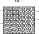
- FIG. 5 is an explanatory diagram of an example in which the arrangement pattern of the plurality of resonant elements 1 is the rectangular arrangement.
- the resonant element 1 is arranged at each vertex of a rectangle, and rectangles are periodically arranged, each including the resonant element 1 arranged at each vertex.
- the rectangle is highlighted by a broken line, and a plurality of the rectangles is arranged.
- FIG. 5 for simplicity of the drawing, only four rectangles are highlighted by broken lines.
- the tip of one of the poles in the resonant element 1 is arranged near the constricted portion in the central part 10 of the adjacent resonant element 1.
- the plurality of resonant elements 1 Since the plurality of resonant elements 1 is densely arranged, even when the incidence angle of the radio wave becomes large, it is capable of obtaining the transmission characteristic and the reflection characteristic over broadband.
- Embodiment 1 discloses the example in which the frequency selective surface of FIG. 2 is a hole-type frequency selective surface.
- Embodiment 2 a case will be described, in which the frequency selective surface of FIG. 2 is a patch-type frequency selective surface.
- the frequency selective surface of FIG. 2 is the patch-type frequency selective surface
- the metal section and the hole section are reversed.
- the resonant element 1 of FIG. 1 that is made of metal is arranged in the hole section of FIG. 2 , and the metal section of FIG. 2 is empty.
- the radio wave is transmitted as it is.
- the reflection coefficient is "0" and the transmission coefficient is "1".
- the reflection coefficient "0" means that there is no radio wave to be reflected.
- the magnitude of the scattered wave propagated depends on the magnitude of the current induced in the resonant element 1.
- a scattering coefficient thereof is "-1".
- the scattering coefficient "-1" means a radio wave of the same magnitude in the direction opposite to the transmitted wave of the incident radio wave.
- the scattered wave propagated to the transmission side and the transmitted wave that is the radio wave transmitted through the space between the plurality of resonant elements 1 in the patch-type frequency selective surface are canceled each other, and the transmission component is "0".
- the radio wave incident on the patch-type frequency selective surface is reflected with a reflection coefficient of "-1".
- the patch-type frequency selective surface operates as a band-stop filter whose reflection coefficient is "-1".
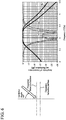
- FIG. 6 is an explanatory diagram of the transmission characteristic and the reflection characteristic of the patch-type frequency selective surface.
- FIG. 6 a two-layer structure is illustrated, in which two frequency selective surfaces shown in FIG. 2 are stacked as the patch-type frequency selective surface of the Embodiment 2.
- the transmission characteristic and the reflection characteristic are illustrated with an assumption that the incidence angle of the radio wave is 40°.
- FIG. 6 for comparing with the patch-type frequency selective surface of the Embodiment 2, the transmission characteristic and the reflection characteristic of a patch-type frequency selective surface are also illustrated, in which resonant elements including rectangular poles are periodically arranged (hereinafter referred to as "a conventional patch-type frequency selective surface").
- the conventional patch-type frequency selective surface is dimensionally optimized such that the transmission characteristic and the reflection characteristic at the incidence angle of 0° are the same as those of the patch-type frequency selective surface of the Embodiment 2.
- the conventional patch-type frequency selective surface is assumed to have a two-layer structure, and the transmission characteristic and the reflection characteristic are illustrated with an assumption that the incidence angle of the radio wave is 40°.
- X 3 indicates the reflection characteristic of the patch-type frequency selective surface of the Embodiment 2
- X 4 indicates the transmission characteristic of the patch-type frequency selective surface of the Embodiment 2.
- Y 3 indicates the reflection characteristic of the conventional patch-type frequency selective surface
- Y 4 indicates the transmission characteristic of the conventional patch-type frequency selective surface
- the reflection characteristic X 3 of the patch-type frequency selective surface of the Embodiment 2 is approximately the same as the reflection characteristic Y 3 of the conventional patch-type frequency selective surface.
- the reflection loss of the patch-type frequency selective surface of the Embodiment 2 is smaller than the reflection loss of the conventional patch-type frequency selective surface.
- the reflection loss of the patch-type frequency selective surface of the Embodiment 2 is about - 22 dB, whereas the reflection loss of the conventional patch-type frequency selective surface is about -30 dB.
- the transmission loss of the patch-type frequency selective surface of the Embodiment 2 is slightly smaller than the transmission loss of the conventional patch-type frequency selective surface.
- the transmission loss of the patch-type frequency selective surface of the Embodiment 2 is considerably larger than the transmission loss of the conventional patch-type frequency selective surface.
- FIG. 6 illustrates the example of the two-layer structure in which two patch-type frequency selective surfaces are stacked, even in the case of a multilayer structure in which three or more patch-type frequency selective surfaces are stacked to be used, or in the case of a single layer structure in which only one patch-type frequency selective surface is used, the transmission characteristic and the reflection characteristic over broadband can be obtained, as in the case of the two-layer structure.
- the poles 11, 12, and 13 whose roots 11a, 12a, and 13a are connected to the central part 10 and whose tips 11b, 12b, and 13b extend in mutually different directions on an identical plane or on an identical curved surface.
- a pole width at each of the roots 11a, 12a, and 13a is narrower than a pole width between each of the roots 11a, 12a, and 13a and the corresponding one of the tips 11b, 12b, and 13b, each pole width being defined by a length of a line segment in a direction perpendicular, on the identical plane or on the identical curved surface, to a line segment connecting each of the roots 11a, 12a, and 13a to a corresponding one of the tips 11b, 12b, and 13b in the respective poles 11, 12, and 13. Therefore, it is possible to obtain the resonant element 1 that can be arranged close to other resonant elements 1 within a range not contacting the other resonant elements 1.
- Embodiments 1 and 2 the frequency selective surface has been described, in which the plurality of resonant elements 1 is arranged on the flat metal plate 2.
- Embodiment 3 a frequency selective surface will be described, in which the plurality of resonant elements 1 is arranged on a metal plate 2 that is a curved plate whose surface is curved.
- FIG. 7 is a structural diagram of the frequency selective surface according to the Embodiment 3 of the present invention.
- FIG. 7A is a diagram of a top view of a frequency selective surface according to Embodiment 3 of the present invention
- FIG. 7B is a diagram of a side view of the frequency selective surface according to the Embodiment 3.
- the frequency selective surface illustrated in FIG. 7 may be the hole-type frequency selective surface or the patch-type frequency selective surface.
- the metal plate 2 is the curved plate, and the plurality of resonant elements 1 is arranged on an identical curved surface.
- the tips 11b, 12b, and 13b of the respective poles 11, 12, and 13 extend in mutually different directions on the identical curved surface. That is, the extending directions of the tips 11b, 12b, and 13b of the respective poles 11, 12, and 13 are shifted by 120° from each other.
- the curved surface shape of the metal plate 2 illustrated in FIG. 7 is an example, and does not limit a curvature, eccentricity, and the like of the curved surface.
- FIG. 8A is a diagram of a top view of a frequency selective surface according to the Embodiment 3 of the present invention
- FIG. 8B is a diagram of a side view of the frequency selective surface according to the Embodiment 3 of the present invention.
- FIG. 8B represents a side view as seen in the direction "A" illustrated in FIG. 8A .
- the shape of the resonant element 1 is a wedge shape in which the central part 10 is constricted as illustrated in FIG. 1 . Therefore, even when the plurality of resonant elements 1 is arranged on the identical curved surface, it is possible to densely arrange the plurality of resonant elements 1 to narrow the interval between the central parts 10, as in the foregoing Embodiments 1 and 2.
- Embodiments 1 to 3 the frequency selective surface has been described, in which the plurality of resonant elements 1 is periodically arranged.
- Embodiment 4 a case will be described, in which the frequency selective surface shown in FIG. 2 , 7 or 8 , in which the plurality of resonant elements 1 is periodically arranged, is incorporated in an antenna device.
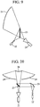
- FIG. 9 is a structural diagram of an antenna device incorporating a frequency selective surface according to the Embodiment 4 of the present invention.
- the antenna device in FIG. 9 represents an example of an offset parabolic antenna in which the frequency selective surface is incorporated.
- a primary radiator 21 is arranged at a position of the focal point of a main reflector 24.
- the primary radiator 21 is a radio wave oscillating source for radiating a radio wave of a frequency band f1.
- a primary radiator 22 is arranged at a position of a mirror image of the focal point with respect to a frequency selective surface 23.
- the primary radiator 22 is a radio wave oscillating source for radiating a radio wave of a frequency band f2.
- the frequency selective surface 23 is the frequency selective surface shown in FIG. 2 .
- the frequency selective surface 23 transmits the radio wave of the frequency band f1 radiated from the primary radiator 21 and reflects the radio wave of the frequency band f2 radiated from the primary radiator 22.
- the frequency selective surface 23 may be the hole-type frequency selective surface or the patch-type frequency selective surface.
- the main reflector 24 is a reflector for reflecting the radio wave of the frequency band f1 transmitted through the frequency selective surface 23 and reflecting the radio wave of the frequency band f2 reflected by the frequency selective surface 23.
- the lengths of the poles 11, 12, and 13 are designed such that the plurality of resonant elements 1 in the frequency selective surface 23 resonates with the radio wave of the frequency band f1 radiated from the primary radiator 21. That is, the lengths of the line segment RS, the line segment FT, and the line segment LU are designed.
- the resonance frequency of the resonant element 1 is determined by the lengths of the poles 11, 12, and 13.
- the lengths of the poles 11, 12, and 13 are designed such that the plurality of resonant elements 1 in the frequency selective surface 23 does not resonate with the radio wave of the frequency band f2 radiated from the primary radiator 22.
- the radio wave of the frequency band f1 radiated from the primary radiator 21 is transmitted through the frequency selective surface 23 and then reflected by the main reflector 24.
- the radio wave of the frequency band f2 radiated from the primary radiator 22 is reflected by the frequency selective surface 23 in a direction where the main reflector 24 exists, and then reflected by the main reflector 24.
- the lengths of the poles 11, 12, and 13 are designed such that the plurality of resonant elements 1 in the frequency selective surface 23 resonates with the radio wave of the frequency band f2 radiated from the primary radiator 22, but does not resonate with the radio wave of the frequency band f1 radiated from the primary radiator 21.
- the antenna device may be an antenna device for receiving the radio wave.
- the radio wave of the frequency band f1 reflected by the main reflector 24 is transmitted through the frequency selective surface 23 and then received by the primary radiator 21.
- the radio wave of the frequency band f2 reflected by the main reflector 24 is reflected by the frequency selective surface 23 in a direction in which the primary radiator 22 exists, and then received by the primary radiator 22.
- the primary radiators 21 and 22 serve as receivers.
- Embodiment 4 it is possible to obtain an antenna device enabled to be commonly used for the frequency band f1 and the frequency band f2.
- the frequency selective surface 23 is the frequency selective surface shown in FIG. 2 by which the broadband transmission characteristic and reflection characteristic can be obtained even when the incidence angle of the radio wave becomes large. Therefore, it is possible to suppress decrease in the gain within the frequency band even when the incidence angle of the radio wave is large.
- the example of the offset parabolic antenna incorporating the frequency selective surface 23 is illustrated.
- the frequency selective surface 23 may be incorporated as part of a focused beam power feeding system that is often used for an antenna device such as a reflector antenna for a large ground station.
- FIG. 10 is a structural diagram of an antenna device incorporating a frequency selective surface according to the Embodiment 4 of the present invention.
- FIG. 10 since the same reference numerals as those in FIG. 9 denote the same or corresponding portions, the description thereof will be omitted.
- a secondary curved mirror 25 is a reflector for reflecting the radio wave of the frequency band f2 radiated from the primary radiator 22.
- the primary radiator 22 is arranged at a position of the focal point of the secondary curved mirror 25.
- a sub-reflector 26 is a reflector for reflecting the radio wave of the frequency band f1 transmitted through the frequency selective surface 23 toward the main reflector 24 and reflecting the radio wave of the frequency band f2 reflected by the frequency selective surface 23 toward the main reflector 24.
- the primary radiator 21 is arranged at a position of the focal point in the sub-reflector 26.
- the antenna device of FIG. 10 similarly to the antenna device of FIG. 9 , it is possible to obtain an antenna device commonly used for the frequency band f1 and the frequency band f2.
- the frequency selective surface 23 is the one shown in FIG. 2 , by which the transmission characteristic and the reflection characteristic over broadband can be obtained even when the incidence angle of the radio wave becomes large. Therefore, it is possible to suppress decrease in the gain within the frequency band even when the incidence angle of the radio wave is large.
- the antenna device is not limited to an antenna device for radiating the radio wave, but may be an antenna device for receiving the radio wave.
- the antenna device includes the frequency selective surface 23 in which the plurality of resonant elements 1 is arranged on the metal plate 2 being a flat plate.
- the antenna device may include a frequency selective surface 27 in which the plurality of resonant elements 1 is arranged on the metal plate 2 being a curved plate.
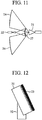
- FIG. 11 is a structural diagram of an antenna device incorporating a frequency selective surface according to the Embodiment 4 of the present invention.
- the same reference numerals as those in FIG. 9 denote the same or corresponding portions, the description thereof will be omitted.
- the frequency selective surface 27 is the one shown in in FIG. 7 or 8 .
- the frequency selective surface 27 transmits the radio wave of the frequency band f1 radiated from the primary radiator 21 and reflects the radio wave of the frequency band f2 radiated from the primary radiator 22.
- the frequency selective surface 27 may be the hole-type frequency selective surface or the patch-type frequency selective surface.
- the radio wave of the frequency band f1 radiated from the primary radiator 21 is transmitted through the frequency selective surface 27 and then reflected by the main reflector 24.
- the radio wave of the frequency band f2 radiated from the primary radiator 22 is reflected by the frequency selective surface 27 in a direction in which the main reflector 24 exists, and then reflected by the main reflector 24.
- the frequency selective surface 27 is the one shown in FIG. 7 or 8 , by which the transmission characteristic and the reflection characteristic over broadband can be obtained even when the incidence angle of the radio wave becomes large. Therefore, it is possible to suppress decrease in the gain within the frequency band even when the incidence angle of the radio wave is large.
- the antenna device is not limited to an antenna device for radiating the radio wave, but may be an antenna device for receiving the radio wave.
- the antenna device includes the frequency selective surface 23 or 27, in which the plurality of resonant elements 1 is periodically arranged.
- the frequency selective surface 23 or 27, on which the plurality of resonant elements 1 is periodically arranged is arranged to cover all or part of the antenna.
- FIG. 12 is a structural diagram of an antenna device incorporating a frequency selective surface according to the Embodiment 5 of the present invention.
- the same reference numerals as those in FIG. 9 denote the same or corresponding portions, the description thereof will be omitted.
- An antenna 31 is installed on an antenna supporting base 32, and transmits or receives a radio wave.
- the antenna 31 may be, for example, an array antenna or a reflector antenna.
- the type of the antenna 31 is not limited to the array antenna or the reflector antenna, and any antenna may be used.
- the antenna supporting base 32 is a base for supporting the antenna 31.
- the frequency selective surface 23 is arranged to cover the front surface being part of the antenna 31.
- the frequency selective surface 23 is the one shown in FIG. 2 , by which the transmission characteristic and the reflection characteristic over broadband can be obtained even when the incidence angle of the radio wave becomes large. Therefore, it is possible to suppress decrease in the gain within the frequency band even when the incidence angle of the radio wave received by the antenna 31 is large, or even when an outgoing angle of the radio wave radiated from the antenna 31 is large.
- the antenna device has been described, in which the frequency selective surface 23 is arranged to cover the front surface of the antenna 31.
- the frequency selective surface 27 may be arranged to cover all the antenna 31.
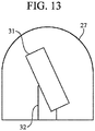
- FIG. 13 is a structural diagram of an antenna device incorporating a frequency selective surface according to the Embodiment 5 of the present invention.
- the same reference numerals as those in FIGS. 11 and 12 denote the same or corresponding portions, the description thereof will be omitted.
- the frequency selective surface 27 is the one shown in FIG. 7 or 8 , by which the transmission characteristic and the reflection characteristic over broadband can be obtained even when the incidence angle of the radio wave becomes large. Therefore, it is possible to suppress decrease in the gain within the frequency band even when the incidence angle of the radio wave received by the antenna 31 is large, or even when an outgoing angle of the radio wave radiated from the antenna 31 is large.
- the present invention is suitable for a frequency selective surface used as a spatial filter and a resonant element used for the frequency selective surface.
Landscapes
- Physics & Mathematics (AREA)
- Electromagnetism (AREA)
- Aerials With Secondary Devices (AREA)
Description
- The present invention relates to a frequency selective surface used as a spatial filter, a resonant element used for the frequency selective surface, and an antenna device mounting the frequency selective surface.
- A frequency selective surface is used as, for example, a spatial filter such as a band-pass filter for transmitting only a radio wave having a desired frequency out of incoming radio waves, or a band-stop filter for reflecting only a radio wave of a desired frequency.
- Thus, the frequency selective surface may be applied to, for example, a multifrequency common reflector antenna, a communication system, a radar system, and the like, for applications such as radio wave interference prevention. The frequency selective surface is mainly classified into a patch-type frequency selective surface and a hole-type frequency selective surface.
- The patch-type frequency selective surface has structure where a plurality of resonant elements, each being made of metal, is periodically arranged.
- The hole-type frequency selective surface is made of a metal plate having a plurality of holes periodically provided. Each of the holes serves as a resonant element.
- The following
Non-Patent Literature 1 discloses a resonant element in which the roots of three poles are connected to the central part and the extending directions of the tips of the three poles are shifted by 120° from each other. Each of the three poles of the resonant element have a rectangular shape. - Non-Patent
Literature 2 discloses a frequency selective surface with fractal resonant elements comprising 4 poles, wherein the roots of the poles are connected to a central part, and wherein the poles are tapered to form pointed tips. -
Patent Literature 1 discloses a frequency selective surface comprising three poles, and wherein the poles are tapered towards the roots. -
- Non-Patent
Literature 1 J. D. Kraus, "Antennas", pp.647-649, McGraw-Hill, 2002 - Non-Patent
Literature 2 A. L. Pereira de Siqueira Campos, "Investigation of Enhancement Band Using Double Screen Frequency Selective Surfaces with Koch Fractal Geometry at Millimeter Wave Range", Journal of Infrared, Millimeter, and Terahertz Waves, vol. 31, pages 1503-1511, 2010. -
Patent Literature 1JP2000196288 A, 2000 - When the frequency selective surface is applied to, for example, a reflector antenna, the incident direction of a radio wave to the frequency selective surface is not necessarily the front direction to the frequency selective surface, and an angle of incidence of the radio wave to the frequency selective surface may become large. Here, it is assumed that, when the incident direction of the radio wave is the front direction of the frequency selective surface, the incidence angle of the radio wave is 0°, whereas the incidence angle becomes larger than 0° as the incident direction shifts from the front direction.
- An index for evaluating the characteristic of the frequency selective surface may be an incidence angle characteristic. It is desirable that a frequency selective surface is capable of obtaining a transmission characteristic and reflection characteristic over broadband even when the incidence angle of the radio wave becomes large.
- In order to improve the incidence angle characteristic, it is necessary to densely arrange the plurality of resonant elements so that the interval between the central parts becomes narrow.
- In addition, it is necessary to widen the area of the pole in order to increase the bandwidth of the resonant element. When the shape of the pole is rectangular, under the condition where the pole length in the longitudinal direction of the rectangle is constant, it is necessary to widen the pole width in the lateral direction of the rectangle. Here it is assumed that the pole length is constant because the resonance frequency of the resonant element may change when the pole length is changed.
- When the plurality of resonant elements, each having rectangular poles whose width is wide, is brought close to each other, the tip of the pole in each resonant element is likely to come into contact with the other resonant element. Therefore, it is impossible to densely arrange the plurality of resonant elements, and there has been a problem that it is difficult to improve the incidence angle characteristic.
- The present invention has been made to solve the above problem. An object of the present invention is to obtain a resonant element of a frequency selective surface, the resonant element being able to be arranged close to other resonant elements within a range not contacting other resonant elements.
- In addition, an object of the present invention is to obtain a frequency selective surface capable of obtaining the transmission characteristic and the reflection characteristic over broadband even when the incidence angle of the radio wave becomes large.
- In addition, an object of the present invention is to obtain an antenna device mounting the frequency selective surface capable of obtaining the transmission characteristic and the reflection characteristic over broadband even when the incidence angle of the radio wave becomes large.
- A resonant element of a frequency selective surface according to the present invention includes: a plurality of poles whose roots are connected to a central part and wherein the poles extend in mutually different directions on an identical plane or on an identical curved surface to define tips at the distal ends thereof, wherein a pole width at each of the roots is narrower than a pole width between each of the roots and the corresponding one of the tips, a pole width at each of the tips is narrower than the pole width at any position between each of the roots and the corresponding one of the tips, each pole width being defined by a length of a line segment that is perpendicular, on the identical plane or on the identical curved surface, to a line segment connecting the centre of each of the roots to the centre of a corresponding one of the tips in the respective poles, such that the pole widths at the roots of the poles are constricted, the poles are tapered towards the tips, and the pole widths are wider at the middle parts of the poles in comparison to those of the roots and the tips.
- According to the present invention, a pole width at each of the roots is narrower than a pole width between each of the roots and the corresponding one of the tips, each pole width being defined by a length of a line segment in a direction perpendicular, on the identical plane or on the identical curved surface, to a line segment connecting each of the roots to a corresponding one of the tips in the respective poles. Therefore, there is an effect that the resonant element can be arranged close to other resonant elements within the range not contacting other resonant elements.
-
- FIG. 1
- is a structural diagram of a resonant element of a frequency selective surface according to
Embodiment 1 of the present invention. - FIG. 2
- is a structural diagram of the frequency selective surface according to the
Embodiment 1 of the present invention. - FIG. 3
- is an explanatory diagram of a transmission characteristic and a reflection characteristic of a hole-type frequency selective surface.
- FIG. 4A
- is an explanatory diagram of a
resonant element 1 in which the tips ofpoles - FIG. 4B
- is an explanatory diagram of a
resonant element 1 in which there are parallel portions between the roots and the tips in thepoles - FIG. 4C
- is an explanatory diagram of a
resonant element 1 in which the roots and the tips of thepoles - FIG. 5
- is an explanatory diagram of a rectangular arrangement of a plurality of the
resonant elements 1. - FIG. 6
- is an explanatory diagram of a transmission characteristic and a reflection characteristic of a patch-type frequency selective surface.
- FIG. 7A
- is a diagram of a top view of a frequency selective surface according to
Embodiment 3 of the present invention, and - FIG. 7B
- is a diagram of a side view of the frequency selective surface according to the
Embodiment 3 of the present invention. - FIG. 8A
- is a diagram of a top view of a frequency selective surface according to the
Embodiment 3 of the present invention, and - FIG. 8B
- is a diagram of a side view of the frequency selective surface according to the
Embodiment 3 of the present invention. - FIG. 9
- is a structural diagram of an antenna device incorporating a frequency selective surface according to
Embodiment 4 of the present invention. - FIG. 10
- is a structural diagram of an antenna device incorporating a frequency selective surface according to the
Embodiment 4 of the present invention. - FIG. 11
- is a structural diagram of an antenna device incorporating a frequency selective surface according to the
Embodiment 4 of the present invention. - FIG. 12
- is a structural diagram of an antenna device incorporating a frequency selective surface according to
Embodiment 5 of the present invention. - FIG. 13
- is a structural diagram of an antenna device incorporating a frequency selective surface according to the
Embodiment 5 of the present invention. - Hereinafter, in order to explain the present invention in more detail, embodiments for carrying out the present invention will be described with reference to the accompanying drawings.
-
FIG. 1 is a structural diagram of a resonant element of a frequency selective surface according to theEmbodiment 1 of the present invention, andFIG. 2 is a structural diagram of the frequency selective surface according to theEmbodiment 1 of the present invention. - In the
Embodiment 1, an example will be described, in which the frequency selective surface is a hole-type frequency selective surface. - The hole-type frequency selective surface is made of a
metal plate 2 having a plurality of holes periodically applied thereto. - In the hole-type frequency selective surface, the holes provided in the
metal plate 2 serve as resonant elements. In theEmbodiment 1, it is assumed that the holes applied in themetal plate 2 are the resonant elements. - In the
Embodiment 1, the shape of each hole in the hole-type frequency selective surface coincides with the shape of theresonant element 1 ofFIG. 1 . - In
FIGS. 1 and2 ,central axes resonant element 1 arranged at an interval of 120°. - A
central part 10 is a part that is positioned at the center of theresonant element 1. - In the example of
FIG. 1 , since threepoles central part 10, the shape of thecentral part 10 is a triangle. The threecentral axes central part 10. - In
FIG. 1 , for convenience of description, while the upper side of the sheet is the reference position, a direction from thecentral part 10 to the upper side of the sheet is represented as 0°, a direction to the lower left side of the sheet is represented as 120°, and a direction to the lower right side of the sheet is represented as 240°. - A to U are signs indicating positions of respective points on the
resonant element 1. - The
metal plate 2 is a flat plate having a flat surface. In themetal plate 2, the holes, each being theresonant element 1 ofFIG. 1 , are periodically arranged. - An arrangement pattern of the
resonant elements 1 is formed such that, as illustrated inFIG. 2 , when attention is paid to tworesonant elements 1 arranged at adjacent positions among the plurality ofresonant elements 1, the tip of one of the poles in one of the tworesonant elements 1 is close to thecentral part 10 of another one of the tworesonant elements 1 within a range not contacting another one of the tworesonant elements 1. - In the
pole 11, aroot 11a is connected to thecentral part 10, and atip 11b extends in the direction of 0°. - The
pole 11 is arranged on the central axis 1a and has a line-symmetrical shape with the central axis 1a as the axis of symmetry. - In the
pole 12, aroot 12a is connected to thecentral part 10, and atip 12b extends in the direction of 120°. - The
pole 12 is arranged on thecentral axis 1b and has a line-symmetrical shape with thecentral axis 1b as the axis of symmetry. - In the
pole 13, aroot 13a is connected to thecentral part 10, and atip 13b extends in the direction of 240°. - The
pole 13 is arranged on thecentral axis 1c and has a line-symmetrical shape with thecentral axis 1c as the axis of symmetry. - In
FIG. 2 , since themetal plate 2 is a flat plate, thetips respective poles tips respective poles - In
FIG. 1 , theresonant element 1 includes the threepoles resonant element 1 may include four or more poles. - When the
resonant element 1 includes, for example, four poles, theresonant element 1 has a shape in which the extending directions of the tips of the four poles are shifted by 90° from each other. As another example, when theresonant element 1 includes five poles, theresonant element 1 has a shape in which the extending directions of the tips of the five poles are shifted by 72° from each other. - In the
pole 11, the pole width at theroot 11a is narrower than the pole width between theroot 11a and thetip 11b. The pole width is the length of the line segment in a direction perpendicular, on the identical plane, to the line segment connecting theroot 11a to thetip 11b in thepole 11. In addition, the pole width at thetip 11b is narrower than the pole width between theroot 11a and thetip 11b. - Specifically, a line segment connecting a point R to a point S (hereinafter referred to as "line segment RS") corresponds to a line segment connecting the
root 11a to thetip 11b in thepole 11. - For example, a line segment connecting a point A to a point Q (hereinafter referred to as "line segment AQ"), a line segment connecting a point C to a point O (hereinafter referred to as "line segment CO"), and a line segment connecting a point B to a point P (hereinafter referred to as "line segment BP") each correspond to a line segment in a direction perpendicular to the line segment RS.
- The length of the line segment CO corresponds to the pole width at the
root 11a, the length of the line segment AQ corresponds to the pole width at thetip 11b, and the length of the line segment BP corresponds to the pole width between theroot 11a and thetip 11b. Hereinafter, the length of the line segment BP is referred to as the pole width of the middle part of thepole 11. - The length of the line segment CO and the length of the line segment AQ are shorter than the length of the line segment BP.
- In the
pole 12, the pole width at theroot 12a is narrower than the pole width between theroot 12a and thetip 12b. The pole width is the length of the line segment in a direction perpendicular, on the identical plane, to the line segment connecting theroot 12a to thetip 12b in thepole 12. In addition, the pole width at thetip 12b is narrower than the pole width between theroot 12a and thetip 12b. - Specifically, a line segment connecting a point F to a point T (hereinafter referred to as "line segment FT") corresponds to a line segment connecting the
root 12a to thetip 12b in thepole 12. - For example, a line segment connecting a point E to a point G (hereinafter referred to as "line segment EG"), a line segment connecting the point C to a point I (hereinafter referred to as "line segment CI"), and a line segment connecting a point D to a point H (hereinafter referred to as "line segment DH") each correspond to a line segment in a direction perpendicular to the line segment FT.
- The length of the line segment CI corresponds to the pole width at the
root 12a, the length of the line segment EG corresponds to the pole width at thetip 12b, and the length of the line segment DH corresponds to the pole width between theroot 12a and thetip 12b. Hereinafter, the length of the line segment DH is referred to as the pole width of the middle part of thepole 12. - The length of the line segment CI and the length of the line segment EG are shorter than the length of the line segment DH.
- In the
pole 13, the pole width at theroot 13a is narrower than the pole width between theroot 13a and thetip 13b. The pole width is the length of the line segment in a direction perpendicular, on the identical plane, to the line segment connecting theroot 13a to thetip 13b in thepole 13. In addition, the pole width at thetip 13b is narrower than the pole width between theroot 13a and thetip 13b. - Specifically, a line segment connecting a point L to a point U (hereinafter referred to as "line segment LU") corresponds to a line segment connecting the
root 13a to thetip 13b in thepole 13. - For example, a line segment connecting a point K to a point M (hereinafter referred to as "line segment KM"), a line segment connecting the point I to the point O (hereinafter referred to as "line segment IO"), and a line segment connecting a point J to a point N (hereinafter referred to as "line segment JN") each correspond to a line segment in a direction perpendicular to the line segment LU.
- The length of the line segment IO corresponds to the pole width at the
root 13a, the length of the line segment KM corresponds to the pole width at thetip 13b, and the length of the line segment JN corresponds to the pole width between theroot 13a and thetip 13b. Hereinafter, the length of the line segment JN is referred to as the pole width of the middle part of thepole 13. - The length of the line segment IO and the length of the line segment KM are shorter than the length of the line segment JN.
- Therefore, in the
poles resonant element 1 ofFIG. 1 , the pole width at each of theroot tips - For this reason, the
resonant element 1 has a wedge shape in which thecentral part 10 is constricted, and thetips respective poles - Since the pole width of the middle part is widened, even when the pole widths at the
root tip entire poles - Next, the operation will be described.
- The operating principle of the hole-type frequency selective surface will be briefly described.
- When a radio wave is incident on a metal plate on which the holes serving as the
resonant elements 1 are not provided, the radio wave is completely reflected by the metal plate. For this reason, the incident radio wave has a reflection coefficient of "-1" and a transmission coefficient of "0". The reflection coefficient of "-1" means that all the incident radio waves are reflected, and the transmission coefficient of "0" means that there is no radio wave to be transmitted. - On the other hand, when a radio wave is incident on the hole-type frequency selective surface on which the holes as the
resonant elements 1 are provided, the radio wave generates an electric field in each of the holes as theresonant elements 1. As a result, a magnetic current is induced in each of theresonant elements 1. - Due to the inducement of the magnetic current, a scattered wave is propagated to both the incident side and the transmission side of the radio wave in the hole-type frequency selective surface.
- The magnitude of the scattered wave propagated depends on the magnitude of the magnetic current induced in the
resonant element 1. When theresonant element 1 completely resonates, a scattering coefficient thereof is "1". The scattering coefficient "1" means a radio wave of the same magnitude in the direction opposite to the reflected wave of the incident radio wave. - As a result, on the incident side, the scattered wave propagated to the incident side and the reflected wave being the radio wave reflected by the metal portion of the hole-type frequency selective surface are canceled each other, and the reflection component is "0". Thus, the radio wave incident on the hole-type frequency selective surface is transmitted with a transmission coefficient of "1". The transmission coefficient "1" means that all the incident radio waves are transmitted.
- Accordingly, when the
resonant element 1 completely resonates, the hole-type frequency selective surface operates as a band-pass filter whose transmission coefficient is "1". - For improving the incidence angle characteristic of the frequency selective surface, it is necessary to densely arrange the plurality of
resonant elements 1 in order to narrow the interval between thecentral parts 10 of theresonant elements 1. - In
FIG. 2 , the plurality ofresonant elements 1 is arranged with an arrangement pattern called a triangular arrangement. - In the triangular arrangement, the
resonant element 1 is arranged at each vertex of an equilateral triangle, and equilateral triangles, each including theresonant element 1 arranged at each vertex, are periodically arranged. - In
FIG. 2 , the equilateral triangle is highlighted by a broken line, and a plurality of the equilateral triangles is arranged to be mingled with each other. InFIG. 2 , for simplicity of the drawing, only four equilateral triangles are highlighted by broken lines. - When attention is paid to a specific
resonant element 1 among the plurality ofresonant elements 1 in the triangular arrangement, the tip of the pole in the specificresonant element 1 is arranged near a constricted portion in thecentral part 10 of an adjacentresonant element 1. - The shape of the
central part 10 of theresonant element 1 of theEmbodiment 1 is a wedge shape having the constricted portion. - In the
Embodiment 1, as compared with a resonant element in which the shape of the pole is rectangular, the tip of the pole can be brought close to thecentral part 10 of the adjacentresonant element 1 by an amount corresponding to the constricted portion without contacting the adjacentresonant element 1. - As a result, even when the incidence angle of the radio wave becomes large, it is capable of obtaining a transmission characteristic and reflection characteristic over broadband.
-
FIG. 3 is an explanatory diagram of the transmission characteristic and the reflection characteristic of the hole-type frequency selective surface. - In
FIG. 3 , a two-layer structure is illustrated, in which two frequency selective surfaces shown inFIG. 2 are stacked as the hole-type frequency selective surface of theEmbodiment 1. In addition, the transmission characteristic and the reflection characteristic are illustrated with an assumption that the incidence angle of the radio wave is 40°. - In
FIG. 3 , for comparing with the hole-type frequency selective surface of theEmbodiment 1, the transmission characteristic and the reflection characteristic of a hole-type frequency selective surface are also illustrated, in which holes as resonant elements are formed by rectangular poles and are periodically provided (hereinafter referred to as "a conventional hole-type frequency selective surface"). - Note that the conventional hole-type frequency selective surface is dimensionally optimized such that the transmission characteristic and the reflection characteristic at the incidence angle of 0° are the same as those of the hole-type frequency selective surface of the
Embodiment 1. - In addition, similarly to the case of the hole-type frequency selective surface of the
Embodiment 1, the conventional hole-type frequency selective surface is assumed to have a two-layer structure, and the transmission characteristic and the reflection characteristic are illustrated with an assumption that the incidence angle of the radio wave is 40°. - In
FIG. 3 , X1 indicates the transmission characteristic of the hole-type frequency selective surface of theEmbodiment 1, and X2 indicates the reflection characteristic of the hole-type frequency selective surface of theEmbodiment 1. - In addition, Y1 indicates the transmission characteristic of the conventional hole-type frequency selective surface, and Y2 indicates the reflection characteristic of the conventional hole-type frequency selective surface.
- When attention is paid to the transmission characteristic, at the radio wave frequency of around 3 GHz to 4.3 GHz, the transmission characteristic X1 of the hole-type frequency selective surface of the
Embodiment 1 is approximately the same as the transmission characteristic Y1 of the conventional hole-type frequency selective surface. - In contrast, at the radio wave frequency of around 4.3 GHz or higher, the transmission loss of the hole-type frequency selective surface of the
Embodiment 1 is smaller than the transmission loss of the conventional hole-type frequency selective surface. For instance, at the radio wave frequency of around 5.5 GHz, the transmission loss of the hole-type frequency selective surface of theEmbodiment 1 is about -22 dB, whereas the transmission loss of the conventional hole-type frequency selective surface is about -30 dB. - Therefore, as compared with the conventional hole-type frequency selective surface, a wider broadband transmission characteristic can be achieved in the hole-type frequency selective surface of the
Embodiment 1. - On the other hand, when attention is paid to the reflection characteristic, at the radio wave frequency of around 3.6 GHz to 3.9 GHz and around 4.1 GHz to 4.2 GHz, the reflection loss of the hole-type frequency selective surface of the
Embodiment 1 is slightly smaller than the reflection loss of the conventional hole-type frequency selective surface. In contrast, at the radio wave frequency of around 3.9 GHz to 4.1 GHz and around 4.2 GHz to 5 GHz, the reflection loss of the hole-type frequency selective surface of theEmbodiment 1 is considerably larger than the reflection loss of the conventional hole-type frequency selective surface. - Therefore, as compared with the conventional hole-type frequency selective surface, a wider broadband reflection characteristic can be achieved in the hole-type frequency selective surface of the
Embodiment 1. - Although
FIG. 3 illustrates the example of the two-layer structure in which two hole-type frequency selective surfaces are stacked, even in the case of a multilayer structure in which three or more hole-type frequency selective surfaces are stacked to be used, or in the case of a single layer structure in which only one hole-type frequency selective surface is used, the transmission characteristic and the reflection characteristic over broadband can be obtained, as in the case of the two-layer structure. - As is apparent from the above description, according to the
Embodiment 1, there are provided thepoles roots central part 10 and whosetips roots roots tips roots tips respective poles resonant element 1 that can be arranged close to otherresonant elements 1 within a range not contacting the otherresonant elements 1. - As a result, even when the incidence angle of the radio wave becomes large, it is possible to obtain a frequency selective surface capable of obtaining the transmission characteristic and the reflection characteristic over broadband.
- In the
Embodiment 1, although theresonant element 1 is shaped as illustrated inFIG. 1 , the shape of thecentral part 10 of theresonant element 1 can be modified so long as it is a wedge shape having the constricted portion. -
FIG. 4 is an explanatory diagram of modifications of theresonant element 1 illustrated inFIG. 1 . -
FIG. 4A illustrates theresonant element 1 in which thetips respective poles -
FIG. 4B illustrates theresonant element 1 in which there are parallel portions between theroots respective tips poles - That is, in the
resonant element 1 illustrated inFIG. 1 , for example, the point B and the point P are angular, whereas, in theresonant element 1 illustrated inFIG. 4B , a part corresponding to the point B and a part corresponding to the point P are parallel to each other. -
FIG. 4C illustrates theresonant element 1 in which the roots and the tips of thepoles - In the
Embodiment 1, the example has been described in which the arrangement pattern of the plurality ofresonant elements 1 is the triangular arrangement. However, the arrangement pattern is not limited to that example so long as the plurality ofresonant elements 1 are densely arranged to narrow the interval between thecentral parts 10 of theresonant elements 1. For example, the arrangement pattern of the plurality ofresonant elements 1 may be a rectangular arrangement. -
FIG. 5 is an explanatory diagram of an example in which the arrangement pattern of the plurality ofresonant elements 1 is the rectangular arrangement. - In the rectangular arrangement, the
resonant element 1 is arranged at each vertex of a rectangle, and rectangles are periodically arranged, each including theresonant element 1 arranged at each vertex. - In
FIG. 5 , the rectangle is highlighted by a broken line, and a plurality of the rectangles is arranged. InFIG. 5 , for simplicity of the drawing, only four rectangles are highlighted by broken lines. - When attention is paid to a certain
resonant element 1 among the plurality ofresonant elements 1 arranged in a rectangle, the tip of one of the poles in theresonant element 1 is arranged near the constricted portion in thecentral part 10 of the adjacentresonant element 1. - Since the plurality of
resonant elements 1 is densely arranged, even when the incidence angle of the radio wave becomes large, it is capable of obtaining the transmission characteristic and the reflection characteristic over broadband. - The foregoing
Embodiment 1 discloses the example in which the frequency selective surface ofFIG. 2 is a hole-type frequency selective surface. In theEmbodiment 2, a case will be described, in which the frequency selective surface ofFIG. 2 is a patch-type frequency selective surface. - When the frequency selective surface of
FIG. 2 is the patch-type frequency selective surface, the metal section and the hole section are reversed. - That is, the
resonant element 1 ofFIG. 1 that is made of metal is arranged in the hole section ofFIG. 2 , and the metal section ofFIG. 2 is empty. - Hereinafter, the operating principle of the patch-type frequency selective surface will be briefly described.
- In a space where the patch-type frequency selective surface does not exist, the radio wave is transmitted as it is. In this case, the reflection coefficient is "0" and the transmission coefficient is "1". The reflection coefficient "0" means that there is no radio wave to be reflected.
- On the other hand, when a radio wave is incident on the patch-type frequency selective surface on which the
resonant elements 1 are arranged, a current is induced in each of theresonant elements 1 by the radio wave. - By the inducement of the current, a scattered wave is propagated to both the incident side and the transmission side of the radio wave in the patch-type frequency selective surface.
- The magnitude of the scattered wave propagated depends on the magnitude of the current induced in the
resonant element 1. When theresonant element 1 completely resonates, a scattering coefficient thereof is "-1". The scattering coefficient "-1" means a radio wave of the same magnitude in the direction opposite to the transmitted wave of the incident radio wave. - As a result, on the transmission side, the scattered wave propagated to the transmission side and the transmitted wave that is the radio wave transmitted through the space between the plurality of
resonant elements 1 in the patch-type frequency selective surface are canceled each other, and the transmission component is "0". Thus, the radio wave incident on the patch-type frequency selective surface is reflected with a reflection coefficient of "-1". - As a result, when the
resonant element 1 completely resonates, the patch-type frequency selective surface operates as a band-stop filter whose reflection coefficient is "-1". -
FIG. 6 is an explanatory diagram of the transmission characteristic and the reflection characteristic of the patch-type frequency selective surface. - In
FIG. 6 , a two-layer structure is illustrated, in which two frequency selective surfaces shown inFIG. 2 are stacked as the patch-type frequency selective surface of theEmbodiment 2. In addition, the transmission characteristic and the reflection characteristic are illustrated with an assumption that the incidence angle of the radio wave is 40°. - In
FIG. 6 , for comparing with the patch-type frequency selective surface of theEmbodiment 2, the transmission characteristic and the reflection characteristic of a patch-type frequency selective surface are also illustrated, in which resonant elements including rectangular poles are periodically arranged (hereinafter referred to as "a conventional patch-type frequency selective surface"). - Note that the conventional patch-type frequency selective surface is dimensionally optimized such that the transmission characteristic and the reflection characteristic at the incidence angle of 0° are the same as those of the patch-type frequency selective surface of the
Embodiment 2. - In addition, similarly to the case of the patch-type frequency selective surface of the
Embodiment 2, the conventional patch-type frequency selective surface is assumed to have a two-layer structure, and the transmission characteristic and the reflection characteristic are illustrated with an assumption that the incidence angle of the radio wave is 40°. - In
FIG. 6 , X3 indicates the reflection characteristic of the patch-type frequency selective surface of theEmbodiment 2, and X4 indicates the transmission characteristic of the patch-type frequency selective surface of theEmbodiment 2. - In addition, Y3 indicates the reflection characteristic of the conventional patch-type frequency selective surface, and Y4 indicates the transmission characteristic of the conventional patch-type frequency selective surface.
- When attention is paid to the reflection characteristic, at the radio wave frequency of around 3 GHz to 4.3 GHz, the reflection characteristic X3 of the patch-type frequency selective surface of the
Embodiment 2 is approximately the same as the reflection characteristic Y3 of the conventional patch-type frequency selective surface. - In contrast, at the radio wave frequency of around 4.3 GHz or higher, the reflection loss of the patch-type frequency selective surface of the
Embodiment 2 is smaller than the reflection loss of the conventional patch-type frequency selective surface. For instance, at the radio wave frequency of about 5.5 GHz, the reflection loss of the patch-type frequency selective surface of theEmbodiment 2 is about - 22 dB, whereas the reflection loss of the conventional patch-type frequency selective surface is about -30 dB. - Therefore, as compared with the conventional patch-type frequency selective surface, a wider broadband reflection characteristic is achieved in the patch-type frequency selective surface of the
Embodiment 2. - On the other hand, when attention is paid to the transmission characteristic, at the radio wave frequency of around 3.6 GHz to 3.9 GHz and around 4.1 GHz to 4.2 GHz, the transmission loss of the patch-type frequency selective surface of the
Embodiment 2 is slightly smaller than the transmission loss of the conventional patch-type frequency selective surface. In contrast, at the radio wave frequency of around 3.9 GHz to 4.1 GHz and around 4.2 GHz to 5 GHz, the transmission loss of the patch-type frequency selective surface of theEmbodiment 2 is considerably larger than the transmission loss of the conventional patch-type frequency selective surface. - Therefore, as compared with the conventional patch-type frequency selective surface, a wider broadband transmission characteristic is achieved in the patch-type frequency selective surface of the
Embodiment 2. - Although
FIG. 6 illustrates the example of the two-layer structure in which two patch-type frequency selective surfaces are stacked, even in the case of a multilayer structure in which three or more patch-type frequency selective surfaces are stacked to be used, or in the case of a single layer structure in which only one patch-type frequency selective surface is used, the transmission characteristic and the reflection characteristic over broadband can be obtained, as in the case of the two-layer structure. - As is apparent from the above description, according to the
Embodiment 2, there are provided thepoles roots central part 10 and whosetips roots roots tips roots tips respective poles resonant element 1 that can be arranged close to otherresonant elements 1 within a range not contacting the otherresonant elements 1. - Therefore, even when the incidence angle of the radio wave becomes large, it is possible to obtain a frequency selective surface capable of obtaining the transmission characteristic and the reflection characteristic over broadband.
- In each of foregoing
Embodiments resonant elements 1 is arranged on theflat metal plate 2. InEmbodiment 3, a frequency selective surface will be described, in which the plurality ofresonant elements 1 is arranged on ametal plate 2 that is a curved plate whose surface is curved. -
FIG. 7 is a structural diagram of the frequency selective surface according to theEmbodiment 3 of the present invention. - Specifically,
FIG. 7A is a diagram of a top view of a frequency selective surface according toEmbodiment 3 of the present invention, andFIG. 7B is a diagram of a side view of the frequency selective surface according to theEmbodiment 3. - The frequency selective surface illustrated in
FIG. 7 may be the hole-type frequency selective surface or the patch-type frequency selective surface. - In
FIG. 7 , themetal plate 2 is the curved plate, and the plurality ofresonant elements 1 is arranged on an identical curved surface. - In the
metal plate 2 being the curved plate, thetips respective poles tips respective poles - Note that the curved surface shape of the
metal plate 2 illustrated inFIG. 7 is an example, and does not limit a curvature, eccentricity, and the like of the curved surface. - Therefore, the plurality of
resonant elements 1 may be arranged on themetal plate 2 having a curved surface shape as illustrated inFIG. 8. FIG. 8A is a diagram of a top view of a frequency selective surface according to theEmbodiment 3 of the present invention, andFIG. 8B is a diagram of a side view of the frequency selective surface according to theEmbodiment 3 of the present invention.FIG. 8B represents a side view as seen in the direction "A" illustrated inFIG. 8A . - The shape of the
resonant element 1 is a wedge shape in which thecentral part 10 is constricted as illustrated inFIG. 1 . Therefore, even when the plurality ofresonant elements 1 is arranged on the identical curved surface, it is possible to densely arrange the plurality ofresonant elements 1 to narrow the interval between thecentral parts 10, as in the foregoing Embodiments 1 and 2. - As a result, even when the incidence angle of the radio wave becomes large, it is possible to obtain a frequency selective surface capable of obtaining the transmission characteristic and the reflection characteristic over broadband.
- In the foregoing
Embodiments 1 to 3, the frequency selective surface has been described, in which the plurality ofresonant elements 1 is periodically arranged. InEmbodiment 4, a case will be described, in which the frequency selective surface shown inFIG. 2 ,7 or8 , in which the plurality ofresonant elements 1 is periodically arranged, is incorporated in an antenna device. -
FIG. 9 is a structural diagram of an antenna device incorporating a frequency selective surface according to theEmbodiment 4 of the present invention. - The antenna device in
FIG. 9 represents an example of an offset parabolic antenna in which the frequency selective surface is incorporated. - In
FIG. 9 , aprimary radiator 21 is arranged at a position of the focal point of amain reflector 24. Theprimary radiator 21 is a radio wave oscillating source for radiating a radio wave of a frequency band f1. - A
primary radiator 22 is arranged at a position of a mirror image of the focal point with respect to a frequencyselective surface 23. Theprimary radiator 22 is a radio wave oscillating source for radiating a radio wave of a frequency band f2. - The frequency
selective surface 23 is the frequency selective surface shown inFIG. 2 . The frequencyselective surface 23 transmits the radio wave of the frequency band f1 radiated from theprimary radiator 21 and reflects the radio wave of the frequency band f2 radiated from theprimary radiator 22. The frequencyselective surface 23 may be the hole-type frequency selective surface or the patch-type frequency selective surface. - The
main reflector 24 is a reflector for reflecting the radio wave of the frequency band f1 transmitted through the frequencyselective surface 23 and reflecting the radio wave of the frequency band f2 reflected by the frequencyselective surface 23. - Next, the operation will be described.
- When the frequency
selective surface 23 is, for example, the hole-type frequency selective surface, the lengths of thepoles resonant elements 1 in the frequencyselective surface 23 resonates with the radio wave of the frequency band f1 radiated from theprimary radiator 21. That is, the lengths of the line segment RS, the line segment FT, and the line segment LU are designed. The resonance frequency of theresonant element 1 is determined by the lengths of thepoles - In addition, the lengths of the
poles resonant elements 1 in the frequencyselective surface 23 does not resonate with the radio wave of the frequency band f2 radiated from theprimary radiator 22. - Thus, the radio wave of the frequency band f1 radiated from the
primary radiator 21 is transmitted through the frequencyselective surface 23 and then reflected by themain reflector 24. - The radio wave of the frequency band f2 radiated from the
primary radiator 22 is reflected by the frequencyselective surface 23 in a direction where themain reflector 24 exists, and then reflected by themain reflector 24. - Note that, when the frequency
selective surface 23 is the patch-type frequency selective surface, the lengths of thepoles resonant elements 1 in the frequencyselective surface 23 resonates with the radio wave of the frequency band f2 radiated from theprimary radiator 22, but does not resonate with the radio wave of the frequency band f1 radiated from theprimary radiator 21. - Although the antenna device for radiating the radio wave has been described, the antenna device may be an antenna device for receiving the radio wave.
- In the case of the antenna device for receiving the radio wave, the radio wave of the frequency band f1 reflected by the
main reflector 24 is transmitted through the frequencyselective surface 23 and then received by theprimary radiator 21. - In addition, the radio wave of the frequency band f2 reflected by the
main reflector 24 is reflected by the frequencyselective surface 23 in a direction in which theprimary radiator 22 exists, and then received by theprimary radiator 22. - In this case, the
primary radiators - According to the
Embodiment 4, it is possible to obtain an antenna device enabled to be commonly used for the frequency band f1 and the frequency band f2. - Note that, the frequency
selective surface 23 is the frequency selective surface shown inFIG. 2 by which the broadband transmission characteristic and reflection characteristic can be obtained even when the incidence angle of the radio wave becomes large. Therefore, it is possible to suppress decrease in the gain within the frequency band even when the incidence angle of the radio wave is large. - In
FIG. 9 , the example of the offset parabolic antenna incorporating the frequencyselective surface 23 is illustrated. Alternatively, as illustrated inFIG. 10 , the frequencyselective surface 23 may be incorporated as part of a focused beam power feeding system that is often used for an antenna device such as a reflector antenna for a large ground station. -
FIG. 10 is a structural diagram of an antenna device incorporating a frequency selective surface according to theEmbodiment 4 of the present invention. InFIG. 10 , since the same reference numerals as those inFIG. 9 denote the same or corresponding portions, the description thereof will be omitted. - A secondary
curved mirror 25 is a reflector for reflecting the radio wave of the frequency band f2 radiated from theprimary radiator 22. Theprimary radiator 22 is arranged at a position of the focal point of the secondarycurved mirror 25. - A sub-reflector 26 is a reflector for reflecting the radio wave of the frequency band f1 transmitted through the frequency
selective surface 23 toward themain reflector 24 and reflecting the radio wave of the frequency band f2 reflected by the frequencyselective surface 23 toward themain reflector 24. Theprimary radiator 21 is arranged at a position of the focal point in the sub-reflector 26. - In the case of the antenna device of
FIG. 10 , similarly to the antenna device ofFIG. 9 , it is possible to obtain an antenna device commonly used for the frequency band f1 and the frequency band f2. - In the case of the antenna device of
FIG. 10 , the frequencyselective surface 23 is the one shown inFIG. 2 , by which the transmission characteristic and the reflection characteristic over broadband can be obtained even when the incidence angle of the radio wave becomes large. Therefore, it is possible to suppress decrease in the gain within the frequency band even when the incidence angle of the radio wave is large. - In the case of the antenna device of
FIG. 10 , similarly toFIG. 9 , the antenna device is not limited to an antenna device for radiating the radio wave, but may be an antenna device for receiving the radio wave. - In
FIG. 9 , the antenna device includes the frequencyselective surface 23 in which the plurality ofresonant elements 1 is arranged on themetal plate 2 being a flat plate. Alternatively, as illustrated inFIG. 11 , the antenna device may include a frequencyselective surface 27 in which the plurality ofresonant elements 1 is arranged on themetal plate 2 being a curved plate. -
FIG. 11 is a structural diagram of an antenna device incorporating a frequency selective surface according to theEmbodiment 4 of the present invention. InFIG. 11 , since the same reference numerals as those inFIG. 9 denote the same or corresponding portions, the description thereof will be omitted. - The frequency
selective surface 27 is the one shown in inFIG. 7 or8 . The frequencyselective surface 27 transmits the radio wave of the frequency band f1 radiated from theprimary radiator 21 and reflects the radio wave of the frequency band f2 radiated from theprimary radiator 22. The frequencyselective surface 27 may be the hole-type frequency selective surface or the patch-type frequency selective surface. - The radio wave of the frequency band f1 radiated from the
primary radiator 21 is transmitted through the frequencyselective surface 27 and then reflected by themain reflector 24. - In addition, the radio wave of the frequency band f2 radiated from the
primary radiator 22 is reflected by the frequencyselective surface 27 in a direction in which themain reflector 24 exists, and then reflected by themain reflector 24. - In the case of the antenna device of
FIG. 11 , similarly toFIG. 9 , it is possible to obtain an antenna device enabled to be commonly used for the frequency band f1 and the frequency band f2. - In the case of the antenna device of
FIG. 11 , the frequencyselective surface 27 is the one shown inFIG. 7 or8 , by which the transmission characteristic and the reflection characteristic over broadband can be obtained even when the incidence angle of the radio wave becomes large. Therefore, it is possible to suppress decrease in the gain within the frequency band even when the incidence angle of the radio wave is large. - In the case of the antenna device of
FIG. 11 , similarly toFIG. 9 , the antenna device is not limited to an antenna device for radiating the radio wave, but may be an antenna device for receiving the radio wave. - In the foregoing
Embodiment 4, the antenna device includes the frequencyselective surface resonant elements 1 is periodically arranged. InEmbodiment 5, the frequencyselective surface resonant elements 1 is periodically arranged, is arranged to cover all or part of the antenna. -
FIG. 12 is a structural diagram of an antenna device incorporating a frequency selective surface according to theEmbodiment 5 of the present invention. InFIG. 12 , since the same reference numerals as those inFIG. 9 denote the same or corresponding portions, the description thereof will be omitted. - An
antenna 31 is installed on anantenna supporting base 32, and transmits or receives a radio wave. - The
antenna 31 may be, for example, an array antenna or a reflector antenna. The type of theantenna 31 is not limited to the array antenna or the reflector antenna, and any antenna may be used. - The
antenna supporting base 32 is a base for supporting theantenna 31. - In the example of
FIG. 12 , the frequencyselective surface 23 is arranged to cover the front surface being part of theantenna 31. - The frequency
selective surface 23 is the one shown inFIG. 2 , by which the transmission characteristic and the reflection characteristic over broadband can be obtained even when the incidence angle of the radio wave becomes large. Therefore, it is possible to suppress decrease in the gain within the frequency band even when the incidence angle of the radio wave received by theantenna 31 is large, or even when an outgoing angle of the radio wave radiated from theantenna 31 is large. - The antenna device has been described, in which the frequency
selective surface 23 is arranged to cover the front surface of theantenna 31. Alternatively, as illustrated inFIG. 13 , the frequencyselective surface 27 may be arranged to cover all theantenna 31. -
FIG. 13 is a structural diagram of an antenna device incorporating a frequency selective surface according to theEmbodiment 5 of the present invention. InFIG. 13 , since the same reference numerals as those inFIGS. 11 and 12 denote the same or corresponding portions, the description thereof will be omitted. - The frequency
selective surface 27 is the one shown inFIG. 7 or8 , by which the transmission characteristic and the reflection characteristic over broadband can be obtained even when the incidence angle of the radio wave becomes large. Therefore, it is possible to suppress decrease in the gain within the frequency band even when the incidence angle of the radio wave received by theantenna 31 is large, or even when an outgoing angle of the radio wave radiated from theantenna 31 is large. - Note that, in the invention of the present application, within the scope of the invention, free combination of each embodiment, a modification of an arbitrary component of each embodiment, or omission of an arbitrary component in each embodiment is possible.
- The present invention is suitable for a frequency selective surface used as a spatial filter and a resonant element used for the frequency selective surface.
-
- 1
- Resonant element
- 1a
- Central axis
- 1b
- Central axis
- 1c
- Central axis
- 2
- Metal plate
- 10
- Central part of resonant element
- 11
- Pole
- 11a
- Root
- 11b
- Tip
- 12
- Pole
- 12a
- Root
- 12b
- Tip
- 13
- Pole
- 13a
- Root
- 13b
- Tip
- 21
- Primary radiator
- 22
- Primary radiator
- 23
- Frequency selective surface
- 24
- Main reflector
- 25
- Secondary curved mirror
- 26
- Sub-reflector
- 27
- Frequency selective surface
- 31
- Antenna
- 32
- Antenna supporting base
Claims (6)
- A resonant element (1) of a frequency selective surface, comprising:a plurality of poles (11, 12, 13) whose roots (11a, 12a, 13a) are connected to a central part (10) and wherein each of the poles (11, 12, 13) extend in mutually different directions on an identical plane or on an identical curved surface to define tips (11b, 12b, 13b) at the distal ends thereof,wherein a pole width at each of the roots (11a, 12a, 13a) is narrower than a pole width at any position between each of the roots (11a, 12a, 13a) and the corresponding one of the tips (11b, 12b, 13b), and a pole width at each of the tips (11b, 12b, 13b) is narrower than the pole width at any position between each of the roots (11a, 12a, 13a) and the corresponding one of the tips (11b, 12b, 13b), each pole width being defined by a length of a line segment that is perpendicular, on the identical plane or on the identical curved surface, to a line segment connecting the centre of each of the roots (11a, 12a, 13a) to the centre of a corresponding one of the tips (11b, 12b, 13b) of the respective poles (11, 12, 13),such that the pole widths at the roots (11a, 12a, 13a) of the poles are constricted, the poles are tapered towards the tips (11b, 12b, 13b), and the pole widths are wider at the middle parts of the poles in comparison to those of the roots and the tips.
- The resonant element (1) of the frequency selective surface according to claim 1, wherein three poles are provided as the plurality of poles (11, 12, 13).
- A frequency selective surface (23), comprising:a plurality of resonant elements (1) arranged in the frequency selective surface (23), each of the resonant elements (1) being specified by claim 1 or 2,wherein an arrangement pattern of the plurality of resonant elements (1) is formed such that, when attention is paid to two resonant elements (1) which are arranged adjacent to each other in the plurality of resonant elements (1), a tip of one of the poles in one of the two resonant elements (1) is close to a central part (10) of another one of the two resonant elements (1) within a range not contacting said another one of the two resonant elements (1).
- An antenna device (31, 32), comprising:
a frequency selective surface (23) according to claim 3 - The antenna device (31, 32) according to claim 4,
further comprising a reflector (24) configured to reflect a radio wave,
wherein the plurality of resonant elements (1) of the frequency selective surface (23) are configured to resonate at a frequency of radio wave that is reflected by the reflector (24). - The antenna device (31, 32) according to claim 4,
further comprising an antenna (31) configured to transmit or receive a radio wave, wherein the frequency selective surface (23) is installed at a position to cover all or part of the antenna (31).
Applications Claiming Priority (1)
| Application Number | Priority Date | Filing Date | Title |
|---|---|---|---|
| PCT/JP2016/061559 WO2017175386A1 (en) | 2016-04-08 | 2016-04-08 | Resonant element for frequency selective plate, frequency selective plate and antenna device |
Publications (3)
| Publication Number | Publication Date |
|---|---|
| EP3442079A1 EP3442079A1 (en) | 2019-02-13 |
| EP3442079A4 EP3442079A4 (en) | 2019-04-10 |
| EP3442079B1 true EP3442079B1 (en) | 2020-11-25 |
Family
ID=57247475
Family Applications (1)
| Application Number | Title | Priority Date | Filing Date |
|---|---|---|---|
| EP16897942.5A Not-in-force EP3442079B1 (en) | 2016-04-08 | 2016-04-08 | Resonant element for frequency selective plate, frequency selective plate and antenna device |
Country Status (5)
| Country | Link |
|---|---|
| US (1) | US10938118B2 (en) |
| EP (1) | EP3442079B1 (en) |
| JP (1) | JP6022139B1 (en) |
| CN (1) | CN108886199B (en) |
| WO (1) | WO2017175386A1 (en) |
Families Citing this family (3)
| Publication number | Priority date | Publication date | Assignee | Title |
|---|---|---|---|---|
| CA3106112A1 (en) | 2018-07-11 | 2020-01-16 | Cld Western Property Holdings Ltd. | Frequency-selective planar radio filter |
| CN115136414B (en) * | 2020-02-27 | 2025-07-25 | 三菱电机株式会社 | Frequency selective surface and radio wave absorber |
| JP7295316B1 (en) * | 2022-08-25 | 2023-06-20 | ソフトバンク株式会社 | Reflective device and system |
Family Cites Families (23)
| Publication number | Priority date | Publication date | Assignee | Title |
|---|---|---|---|---|
| JP2542456B2 (en) * | 1990-08-31 | 1996-10-09 | 日本電信電話株式会社 | Frequency selection mirror surface |
| JPH0514050A (en) * | 1991-07-05 | 1993-01-22 | Mitsubishi Electric Corp | Antenna device |
| SE504815C2 (en) | 1995-08-17 | 1997-04-28 | Ericsson Telefon Ab L M | Protection for one or more electromagnetic sensors |
| JP2000196288A (en) * | 1996-08-30 | 2000-07-14 | Kajima Corp | Electromagnetic shield structure |
| KR100315537B1 (en) * | 1996-08-30 | 2002-04-24 | 우메다 사다오 | Window glass with electronic shield performance |
| JP3079364B2 (en) * | 1996-08-30 | 2000-08-21 | 鹿島建設株式会社 | Window glass with electromagnetic shielding performance |
| US5892485A (en) * | 1997-02-25 | 1999-04-06 | Pacific Antenna Technologies | Dual frequency reflector antenna feed element |
| JP2001298322A (en) * | 2000-04-11 | 2001-10-26 | Sumitomo Electric Ind Ltd | Aircraft radome |
| US6512485B2 (en) | 2001-03-12 | 2003-01-28 | Wildblue Communications, Inc. | Multi-band antenna for bundled broadband satellite internet access and DBS television service |
| US6407716B1 (en) * | 2001-04-19 | 2002-06-18 | Ems Technologies Canada, Ltd. | Broadband dichroic surface |
| CN1898837A (en) * | 2003-11-21 | 2007-01-17 | 阿蒂密有限公司 | Ultrawide antenna |
| WO2006098587A1 (en) * | 2005-03-15 | 2006-09-21 | Electronics And Telecommunications Research Institute | Freuqency selective surface for the filtering of freuqency band and design method thereof |
| US7859482B1 (en) * | 2006-09-27 | 2010-12-28 | Rockwell Collins, Inc. | Frequency selective surface waveguide switch |
| US8106850B1 (en) * | 2006-12-21 | 2012-01-31 | Hrl Laboratories, Llc | Adaptive spectral surface |
| US8017217B1 (en) | 2008-05-09 | 2011-09-13 | Hrl Laboratories, Llc | Variable emissivity material |
| US9368879B1 (en) * | 2011-05-25 | 2016-06-14 | The Boeing Company | Ultra wide band antenna element |
| CN102694271A (en) * | 2012-04-28 | 2012-09-26 | 深圳光启创新技术有限公司 | Multi-resonant metamaterial, antenna radome and antenna system thereof |
| CN102769203B (en) * | 2012-07-03 | 2015-06-03 | 深圳光启创新技术有限公司 | Metamaterial frequency selective surface, metamaterial frequency selective radome and antenna system made of metamaterial frequency selective surface |
| CN103401049A (en) * | 2013-08-07 | 2013-11-20 | 中国科学院长春光学精密机械与物理研究所 | Stable-polarization performance thick-screen frequency selective surface filter |
| TWI514680B (en) * | 2014-03-17 | 2015-12-21 | Wistron Neweb Corp | Multiband antenna and multiband antenna configuration method |
| US20170097630A1 (en) * | 2014-03-24 | 2017-04-06 | President And Fellows Of Harvard College | Shadow sphere lithography |
| CN104538710B (en) * | 2015-01-23 | 2017-10-03 | 东南大学 | A kind of frequency-selective surfaces structure |
| CN105406156A (en) * | 2015-11-27 | 2016-03-16 | 哈尔滨工业大学 | Cylindrical frequency selective surface structure |
-
2016
- 2016-04-08 EP EP16897942.5A patent/EP3442079B1/en not_active Not-in-force
- 2016-04-08 WO PCT/JP2016/061559 patent/WO2017175386A1/en not_active Ceased
- 2016-04-08 US US16/080,170 patent/US10938118B2/en not_active Expired - Fee Related
- 2016-04-08 CN CN201680084231.2A patent/CN108886199B/en not_active Expired - Fee Related
- 2016-04-08 JP JP2016549540A patent/JP6022139B1/en not_active Expired - Fee Related
Non-Patent Citations (1)
| Title |
|---|
| None * |
Also Published As
| Publication number | Publication date |
|---|---|
| US20190058258A1 (en) | 2019-02-21 |
| EP3442079A4 (en) | 2019-04-10 |
| WO2017175386A1 (en) | 2017-10-12 |
| US10938118B2 (en) | 2021-03-02 |
| JPWO2017175386A1 (en) | 2018-04-12 |
| JP6022139B1 (en) | 2016-11-09 |
| CN108886199B (en) | 2021-06-22 |
| CN108886199A (en) | 2018-11-23 |
| EP3442079A1 (en) | 2019-02-13 |
Similar Documents
| Publication | Publication Date | Title |
|---|---|---|
| JP7500172B2 (en) | Metasurface reflector and traffic light equipped with said metasurface | |
| JP5738437B2 (en) | Dual polarization antenna for mobile communication base station and multiband antenna system using the same | |
| EP2752942B1 (en) | Omnidirectional antenna | |
| CN205646175U (en) | Antenna and sector antenna | |
| EP3301756B1 (en) | Radiation device | |
| CN111403899B (en) | Multi-frequency antenna structure | |
| EP2827450A1 (en) | Dual antenna apparatus | |
| KR20050103608A (en) | Square Lattice Horn Array Antenna for Circularly Polarized Reception | |
| US10938118B2 (en) | Resonant element of frequency selective surface, frequency selective surface and antenna device | |
| JP2022544961A (en) | Full-band quadrature mode converter | |
| CN103700949A (en) | Hyperbolic frequency selection surface spectroscope | |
| CN109037953B (en) | A dual-polarized broadband radiation unit and antenna | |
| JP5762162B2 (en) | Microstrip antenna and array antenna using the antenna | |
| Lee et al. | A wideband planar monopole antenna array with circular polarized and band-notched characteristics | |
| EP3547451B1 (en) | Reflection mirror antenna device | |
| CN108281795B (en) | Frequency selection surface type curved surface medium and Cassegrain antenna system | |
| CN112751164A (en) | High-gain antenna oscillator | |
| CN106170889A (en) | Antennas and Sector Antennas | |
| US20060119529A1 (en) | Ultra wideband antenna | |
| JP2016092633A (en) | Reflect array antenna | |
| JP5827470B2 (en) | Sector antenna | |
| JP4879289B2 (en) | Dual frequency planar antenna | |
| KR102856516B1 (en) | Magneto electric angled dipole antenna | |
| JP5752176B2 (en) | Omni antenna | |
| RU2157580C1 (en) | Wide-band directional antenna |
Legal Events
| Date | Code | Title | Description |
|---|---|---|---|
| STAA | Information on the status of an ep patent application or granted ep patent |
Free format text: STATUS: THE INTERNATIONAL PUBLICATION HAS BEEN MADE |
|
| PUAI | Public reference made under article 153(3) epc to a published international application that has entered the european phase |
Free format text: ORIGINAL CODE: 0009012 |
|
| STAA | Information on the status of an ep patent application or granted ep patent |
Free format text: STATUS: REQUEST FOR EXAMINATION WAS MADE |
|
| 17P | Request for examination filed |
Effective date: 20181002 |
|
| AK | Designated contracting states |
Kind code of ref document: A1 Designated state(s): AL AT BE BG CH CY CZ DE DK EE ES FI FR GB GR HR HU IE IS IT LI LT LU LV MC MK MT NL NO PL PT RO RS SE SI SK SM TR |
|
| AX | Request for extension of the european patent |
Extension state: BA ME |
|
| A4 | Supplementary search report drawn up and despatched |
Effective date: 20190313 |
|
| RIC1 | Information provided on ipc code assigned before grant |
Ipc: H01Q 15/02 20060101ALI20190306BHEP Ipc: H01Q 15/14 20060101AFI20190306BHEP Ipc: H01Q 15/00 20060101ALI20190306BHEP |
|
| DAV | Request for validation of the european patent (deleted) | ||
| DAX | Request for extension of the european patent (deleted) | ||
| REG | Reference to a national code |
Ref country code: DE Ref legal event code: R079 Ref document number: 602016048843 Country of ref document: DE Free format text: PREVIOUS MAIN CLASS: H01Q0015140000 Ipc: H01Q0015000000 |
|
| GRAP | Despatch of communication of intention to grant a patent |
Free format text: ORIGINAL CODE: EPIDOSNIGR1 |
|
| STAA | Information on the status of an ep patent application or granted ep patent |
Free format text: STATUS: GRANT OF PATENT IS INTENDED |
|
| RIC1 | Information provided on ipc code assigned before grant |
Ipc: H01Q 15/00 20060101AFI20200508BHEP |
|
| INTG | Intention to grant announced |
Effective date: 20200604 |
|
| GRAS | Grant fee paid |
Free format text: ORIGINAL CODE: EPIDOSNIGR3 |
|
| GRAA | (expected) grant |
Free format text: ORIGINAL CODE: 0009210 |
|
| STAA | Information on the status of an ep patent application or granted ep patent |
Free format text: STATUS: THE PATENT HAS BEEN GRANTED |
|
| AK | Designated contracting states |
Kind code of ref document: B1 Designated state(s): AL AT BE BG CH CY CZ DE DK EE ES FI FR GB GR HR HU IE IS IT LI LT LU LV MC MK MT NL NO PL PT RO RS SE SI SK SM TR |
|
| REG | Reference to a national code |
Ref country code: GB Ref legal event code: FG4D |
|
| REG | Reference to a national code |
Ref country code: CH Ref legal event code: EP |
|
| REG | Reference to a national code |
Ref country code: AT Ref legal event code: REF Ref document number: 1339351 Country of ref document: AT Kind code of ref document: T Effective date: 20201215 |
|
| REG | Reference to a national code |
Ref country code: DE Ref legal event code: R096 Ref document number: 602016048843 Country of ref document: DE |
|
| REG | Reference to a national code |
Ref country code: IE Ref legal event code: FG4D |
|
| REG | Reference to a national code |
Ref country code: AT Ref legal event code: MK05 Ref document number: 1339351 Country of ref document: AT Kind code of ref document: T Effective date: 20201125 |
|
| REG | Reference to a national code |
Ref country code: NL Ref legal event code: MP Effective date: 20201125 |
|
| PG25 | Lapsed in a contracting state [announced via postgrant information from national office to epo] |
Ref country code: GR Free format text: LAPSE BECAUSE OF FAILURE TO SUBMIT A TRANSLATION OF THE DESCRIPTION OR TO PAY THE FEE WITHIN THE PRESCRIBED TIME-LIMIT Effective date: 20210226 Ref country code: FI Free format text: LAPSE BECAUSE OF FAILURE TO SUBMIT A TRANSLATION OF THE DESCRIPTION OR TO PAY THE FEE WITHIN THE PRESCRIBED TIME-LIMIT Effective date: 20201125 Ref country code: PT Free format text: LAPSE BECAUSE OF FAILURE TO SUBMIT A TRANSLATION OF THE DESCRIPTION OR TO PAY THE FEE WITHIN THE PRESCRIBED TIME-LIMIT Effective date: 20210325 Ref country code: RS Free format text: LAPSE BECAUSE OF FAILURE TO SUBMIT A TRANSLATION OF THE DESCRIPTION OR TO PAY THE FEE WITHIN THE PRESCRIBED TIME-LIMIT Effective date: 20201125 Ref country code: NO Free format text: LAPSE BECAUSE OF FAILURE TO SUBMIT A TRANSLATION OF THE DESCRIPTION OR TO PAY THE FEE WITHIN THE PRESCRIBED TIME-LIMIT Effective date: 20210225 |
|
| PG25 | Lapsed in a contracting state [announced via postgrant information from national office to epo] |
Ref country code: AT Free format text: LAPSE BECAUSE OF FAILURE TO SUBMIT A TRANSLATION OF THE DESCRIPTION OR TO PAY THE FEE WITHIN THE PRESCRIBED TIME-LIMIT Effective date: 20201125 Ref country code: IS Free format text: LAPSE BECAUSE OF FAILURE TO SUBMIT A TRANSLATION OF THE DESCRIPTION OR TO PAY THE FEE WITHIN THE PRESCRIBED TIME-LIMIT Effective date: 20210325 Ref country code: LV Free format text: LAPSE BECAUSE OF FAILURE TO SUBMIT A TRANSLATION OF THE DESCRIPTION OR TO PAY THE FEE WITHIN THE PRESCRIBED TIME-LIMIT Effective date: 20201125 Ref country code: PL Free format text: LAPSE BECAUSE OF FAILURE TO SUBMIT A TRANSLATION OF THE DESCRIPTION OR TO PAY THE FEE WITHIN THE PRESCRIBED TIME-LIMIT Effective date: 20201125 Ref country code: BG Free format text: LAPSE BECAUSE OF FAILURE TO SUBMIT A TRANSLATION OF THE DESCRIPTION OR TO PAY THE FEE WITHIN THE PRESCRIBED TIME-LIMIT Effective date: 20210225 Ref country code: SE Free format text: LAPSE BECAUSE OF FAILURE TO SUBMIT A TRANSLATION OF THE DESCRIPTION OR TO PAY THE FEE WITHIN THE PRESCRIBED TIME-LIMIT Effective date: 20201125 |
|
| REG | Reference to a national code |
Ref country code: LT Ref legal event code: MG9D |
|
| PG25 | Lapsed in a contracting state [announced via postgrant information from national office to epo] |
Ref country code: HR Free format text: LAPSE BECAUSE OF FAILURE TO SUBMIT A TRANSLATION OF THE DESCRIPTION OR TO PAY THE FEE WITHIN THE PRESCRIBED TIME-LIMIT Effective date: 20201125 |
|
| PG25 | Lapsed in a contracting state [announced via postgrant information from national office to epo] |
Ref country code: CZ Free format text: LAPSE BECAUSE OF FAILURE TO SUBMIT A TRANSLATION OF THE DESCRIPTION OR TO PAY THE FEE WITHIN THE PRESCRIBED TIME-LIMIT Effective date: 20201125 Ref country code: EE Free format text: LAPSE BECAUSE OF FAILURE TO SUBMIT A TRANSLATION OF THE DESCRIPTION OR TO PAY THE FEE WITHIN THE PRESCRIBED TIME-LIMIT Effective date: 20201125 Ref country code: SM Free format text: LAPSE BECAUSE OF FAILURE TO SUBMIT A TRANSLATION OF THE DESCRIPTION OR TO PAY THE FEE WITHIN THE PRESCRIBED TIME-LIMIT Effective date: 20201125 Ref country code: LT Free format text: LAPSE BECAUSE OF FAILURE TO SUBMIT A TRANSLATION OF THE DESCRIPTION OR TO PAY THE FEE WITHIN THE PRESCRIBED TIME-LIMIT Effective date: 20201125 Ref country code: RO Free format text: LAPSE BECAUSE OF FAILURE TO SUBMIT A TRANSLATION OF THE DESCRIPTION OR TO PAY THE FEE WITHIN THE PRESCRIBED TIME-LIMIT Effective date: 20201125 Ref country code: SK Free format text: LAPSE BECAUSE OF FAILURE TO SUBMIT A TRANSLATION OF THE DESCRIPTION OR TO PAY THE FEE WITHIN THE PRESCRIBED TIME-LIMIT Effective date: 20201125 |
|
| REG | Reference to a national code |
Ref country code: DE Ref legal event code: R097 Ref document number: 602016048843 Country of ref document: DE |
|
| PG25 | Lapsed in a contracting state [announced via postgrant information from national office to epo] |
Ref country code: DK Free format text: LAPSE BECAUSE OF FAILURE TO SUBMIT A TRANSLATION OF THE DESCRIPTION OR TO PAY THE FEE WITHIN THE PRESCRIBED TIME-LIMIT Effective date: 20201125 |
|
| PLBE | No opposition filed within time limit |
Free format text: ORIGINAL CODE: 0009261 |
|
| STAA | Information on the status of an ep patent application or granted ep patent |
Free format text: STATUS: NO OPPOSITION FILED WITHIN TIME LIMIT |
|
| PG25 | Lapsed in a contracting state [announced via postgrant information from national office to epo] |
Ref country code: NL Free format text: LAPSE BECAUSE OF FAILURE TO SUBMIT A TRANSLATION OF THE DESCRIPTION OR TO PAY THE FEE WITHIN THE PRESCRIBED TIME-LIMIT Effective date: 20201125 Ref country code: AL Free format text: LAPSE BECAUSE OF FAILURE TO SUBMIT A TRANSLATION OF THE DESCRIPTION OR TO PAY THE FEE WITHIN THE PRESCRIBED TIME-LIMIT Effective date: 20201125 |
|
| 26N | No opposition filed |
Effective date: 20210826 |
|
| PG25 | Lapsed in a contracting state [announced via postgrant information from national office to epo] |
Ref country code: SI Free format text: LAPSE BECAUSE OF FAILURE TO SUBMIT A TRANSLATION OF THE DESCRIPTION OR TO PAY THE FEE WITHIN THE PRESCRIBED TIME-LIMIT Effective date: 20201125 Ref country code: MC Free format text: LAPSE BECAUSE OF FAILURE TO SUBMIT A TRANSLATION OF THE DESCRIPTION OR TO PAY THE FEE WITHIN THE PRESCRIBED TIME-LIMIT Effective date: 20201125 |
|
| GBPC | Gb: european patent ceased through non-payment of renewal fee |
Effective date: 20210408 |
|
| PG25 | Lapsed in a contracting state [announced via postgrant information from national office to epo] |
Ref country code: LU Free format text: LAPSE BECAUSE OF NON-PAYMENT OF DUE FEES Effective date: 20210408 |
|
| REG | Reference to a national code |
Ref country code: BE Ref legal event code: MM Effective date: 20210430 |
|
| PG25 | Lapsed in a contracting state [announced via postgrant information from national office to epo] |
Ref country code: LI Free format text: LAPSE BECAUSE OF NON-PAYMENT OF DUE FEES Effective date: 20210430 Ref country code: CH Free format text: LAPSE BECAUSE OF NON-PAYMENT OF DUE FEES Effective date: 20210430 Ref country code: ES Free format text: LAPSE BECAUSE OF FAILURE TO SUBMIT A TRANSLATION OF THE DESCRIPTION OR TO PAY THE FEE WITHIN THE PRESCRIBED TIME-LIMIT Effective date: 20201125 Ref country code: GB Free format text: LAPSE BECAUSE OF NON-PAYMENT OF DUE FEES Effective date: 20210408 |
|
| PG25 | Lapsed in a contracting state [announced via postgrant information from national office to epo] |
Ref country code: IE Free format text: LAPSE BECAUSE OF NON-PAYMENT OF DUE FEES Effective date: 20210408 |
|
| PG25 | Lapsed in a contracting state [announced via postgrant information from national office to epo] |
Ref country code: IS Free format text: LAPSE BECAUSE OF FAILURE TO SUBMIT A TRANSLATION OF THE DESCRIPTION OR TO PAY THE FEE WITHIN THE PRESCRIBED TIME-LIMIT Effective date: 20210325 |
|
| PG25 | Lapsed in a contracting state [announced via postgrant information from national office to epo] |
Ref country code: BE Free format text: LAPSE BECAUSE OF NON-PAYMENT OF DUE FEES Effective date: 20210430 |
|
| PGFP | Annual fee paid to national office [announced via postgrant information from national office to epo] |
Ref country code: FR Payment date: 20230309 Year of fee payment: 8 |
|
| PGFP | Annual fee paid to national office [announced via postgrant information from national office to epo] |
Ref country code: IT Payment date: 20230310 Year of fee payment: 8 |
|
| P01 | Opt-out of the competence of the unified patent court (upc) registered |
Effective date: 20230512 |
|
| PG25 | Lapsed in a contracting state [announced via postgrant information from national office to epo] |
Ref country code: CY Free format text: LAPSE BECAUSE OF FAILURE TO SUBMIT A TRANSLATION OF THE DESCRIPTION OR TO PAY THE FEE WITHIN THE PRESCRIBED TIME-LIMIT Effective date: 20201125 |
|
| PG25 | Lapsed in a contracting state [announced via postgrant information from national office to epo] |
Ref country code: HU Free format text: LAPSE BECAUSE OF FAILURE TO SUBMIT A TRANSLATION OF THE DESCRIPTION OR TO PAY THE FEE WITHIN THE PRESCRIBED TIME-LIMIT; INVALID AB INITIO Effective date: 20160408 |
|
| PGFP | Annual fee paid to national office [announced via postgrant information from national office to epo] |
Ref country code: DE Payment date: 20230228 Year of fee payment: 8 |
|
| PG25 | Lapsed in a contracting state [announced via postgrant information from national office to epo] |
Ref country code: MK Free format text: LAPSE BECAUSE OF FAILURE TO SUBMIT A TRANSLATION OF THE DESCRIPTION OR TO PAY THE FEE WITHIN THE PRESCRIBED TIME-LIMIT Effective date: 20201125 |
|
| PG25 | Lapsed in a contracting state [announced via postgrant information from national office to epo] |
Ref country code: TR Free format text: LAPSE BECAUSE OF FAILURE TO SUBMIT A TRANSLATION OF THE DESCRIPTION OR TO PAY THE FEE WITHIN THE PRESCRIBED TIME-LIMIT Effective date: 20201125 |
|
| PG25 | Lapsed in a contracting state [announced via postgrant information from national office to epo] |
Ref country code: MT Free format text: LAPSE BECAUSE OF FAILURE TO SUBMIT A TRANSLATION OF THE DESCRIPTION OR TO PAY THE FEE WITHIN THE PRESCRIBED TIME-LIMIT Effective date: 20201125 |
|
| REG | Reference to a national code |
Ref country code: DE Ref legal event code: R119 Ref document number: 602016048843 Country of ref document: DE |
|
| PG25 | Lapsed in a contracting state [announced via postgrant information from national office to epo] |
Ref country code: DE Free format text: LAPSE BECAUSE OF NON-PAYMENT OF DUE FEES Effective date: 20241105 |
|
| PG25 | Lapsed in a contracting state [announced via postgrant information from national office to epo] |
Ref country code: FR Free format text: LAPSE BECAUSE OF NON-PAYMENT OF DUE FEES Effective date: 20240430 |
|
| PG25 | Lapsed in a contracting state [announced via postgrant information from national office to epo] |
Ref country code: FR Free format text: LAPSE BECAUSE OF NON-PAYMENT OF DUE FEES Effective date: 20240430 Ref country code: DE Free format text: LAPSE BECAUSE OF NON-PAYMENT OF DUE FEES Effective date: 20241105 |
|
| PG25 | Lapsed in a contracting state [announced via postgrant information from national office to epo] |
Ref country code: IT Free format text: LAPSE BECAUSE OF NON-PAYMENT OF DUE FEES Effective date: 20240408 |