EP3442049A1 - Battery module - Google Patents
Battery module Download PDFInfo
- Publication number
- EP3442049A1 EP3442049A1 EP17205132.8A EP17205132A EP3442049A1 EP 3442049 A1 EP3442049 A1 EP 3442049A1 EP 17205132 A EP17205132 A EP 17205132A EP 3442049 A1 EP3442049 A1 EP 3442049A1
- Authority
- EP
- European Patent Office
- Prior art keywords
- cooling channel
- cell cover
- cell
- battery module
- battery
- Prior art date
- Legal status (The legal status is an assumption and is not a legal conclusion. Google has not performed a legal analysis and makes no representation as to the accuracy of the status listed.)
- Granted
Links
Images


Classifications
-
- H—ELECTRICITY
- H01—ELECTRIC ELEMENTS
- H01M—PROCESSES OR MEANS, e.g. BATTERIES, FOR THE DIRECT CONVERSION OF CHEMICAL ENERGY INTO ELECTRICAL ENERGY
- H01M10/00—Secondary cells; Manufacture thereof
- H01M10/60—Heating or cooling; Temperature control
- H01M10/65—Means for temperature control structurally associated with the cells
- H01M10/655—Solid structures for heat exchange or heat conduction
- H01M10/6551—Surfaces specially adapted for heat dissipation or radiation, e.g. fins or coatings
-
- H—ELECTRICITY
- H01—ELECTRIC ELEMENTS
- H01M—PROCESSES OR MEANS, e.g. BATTERIES, FOR THE DIRECT CONVERSION OF CHEMICAL ENERGY INTO ELECTRICAL ENERGY
- H01M10/00—Secondary cells; Manufacture thereof
- H01M10/60—Heating or cooling; Temperature control
- H01M10/61—Types of temperature control
- H01M10/613—Cooling or keeping cold
-
- H—ELECTRICITY
- H01—ELECTRIC ELEMENTS
- H01M—PROCESSES OR MEANS, e.g. BATTERIES, FOR THE DIRECT CONVERSION OF CHEMICAL ENERGY INTO ELECTRICAL ENERGY
- H01M10/00—Secondary cells; Manufacture thereof
- H01M10/60—Heating or cooling; Temperature control
- H01M10/62—Heating or cooling; Temperature control specially adapted for specific applications
- H01M10/625—Vehicles
-
- H—ELECTRICITY
- H01—ELECTRIC ELEMENTS
- H01M—PROCESSES OR MEANS, e.g. BATTERIES, FOR THE DIRECT CONVERSION OF CHEMICAL ENERGY INTO ELECTRICAL ENERGY
- H01M10/00—Secondary cells; Manufacture thereof
- H01M10/60—Heating or cooling; Temperature control
- H01M10/64—Heating or cooling; Temperature control characterised by the shape of the cells
- H01M10/647—Prismatic or flat cells, e.g. pouch cells
-
- H—ELECTRICITY
- H01—ELECTRIC ELEMENTS
- H01M—PROCESSES OR MEANS, e.g. BATTERIES, FOR THE DIRECT CONVERSION OF CHEMICAL ENERGY INTO ELECTRICAL ENERGY
- H01M10/00—Secondary cells; Manufacture thereof
- H01M10/60—Heating or cooling; Temperature control
- H01M10/65—Means for temperature control structurally associated with the cells
- H01M10/655—Solid structures for heat exchange or heat conduction
- H01M10/6554—Rods or plates
-
- H—ELECTRICITY
- H01—ELECTRIC ELEMENTS
- H01M—PROCESSES OR MEANS, e.g. BATTERIES, FOR THE DIRECT CONVERSION OF CHEMICAL ENERGY INTO ELECTRICAL ENERGY
- H01M10/00—Secondary cells; Manufacture thereof
- H01M10/60—Heating or cooling; Temperature control
- H01M10/65—Means for temperature control structurally associated with the cells
- H01M10/655—Solid structures for heat exchange or heat conduction
- H01M10/6554—Rods or plates
- H01M10/6555—Rods or plates arranged between the cells
-
- H—ELECTRICITY
- H01—ELECTRIC ELEMENTS
- H01M—PROCESSES OR MEANS, e.g. BATTERIES, FOR THE DIRECT CONVERSION OF CHEMICAL ENERGY INTO ELECTRICAL ENERGY
- H01M10/00—Secondary cells; Manufacture thereof
- H01M10/60—Heating or cooling; Temperature control
- H01M10/65—Means for temperature control structurally associated with the cells
- H01M10/655—Solid structures for heat exchange or heat conduction
- H01M10/6556—Solid parts with flow channel passages or pipes for heat exchange
-
- H—ELECTRICITY
- H01—ELECTRIC ELEMENTS
- H01M—PROCESSES OR MEANS, e.g. BATTERIES, FOR THE DIRECT CONVERSION OF CHEMICAL ENERGY INTO ELECTRICAL ENERGY
- H01M10/00—Secondary cells; Manufacture thereof
- H01M10/60—Heating or cooling; Temperature control
- H01M10/65—Means for temperature control structurally associated with the cells
- H01M10/656—Means for temperature control structurally associated with the cells characterised by the type of heat-exchange fluid
- H01M10/6567—Liquids
-
- H—ELECTRICITY
- H01—ELECTRIC ELEMENTS
- H01M—PROCESSES OR MEANS, e.g. BATTERIES, FOR THE DIRECT CONVERSION OF CHEMICAL ENERGY INTO ELECTRICAL ENERGY
- H01M10/00—Secondary cells; Manufacture thereof
- H01M10/60—Heating or cooling; Temperature control
- H01M10/65—Means for temperature control structurally associated with the cells
- H01M10/656—Means for temperature control structurally associated with the cells characterised by the type of heat-exchange fluid
- H01M10/6567—Liquids
- H01M10/6568—Liquids characterised by flow circuits, e.g. loops, located externally to the cells or cell casings
-
- H—ELECTRICITY
- H01—ELECTRIC ELEMENTS
- H01M—PROCESSES OR MEANS, e.g. BATTERIES, FOR THE DIRECT CONVERSION OF CHEMICAL ENERGY INTO ELECTRICAL ENERGY
- H01M50/00—Constructional details or processes of manufacture of the non-active parts of electrochemical cells other than fuel cells, e.g. hybrid cells
- H01M50/20—Mountings; Secondary casings or frames; Racks, modules or packs; Suspension devices; Shock absorbers; Transport or carrying devices; Holders
- H01M50/204—Racks, modules or packs for multiple batteries or multiple cells
- H01M50/207—Racks, modules or packs for multiple batteries or multiple cells characterised by their shape
- H01M50/211—Racks, modules or packs for multiple batteries or multiple cells characterised by their shape adapted for pouch cells
-
- H—ELECTRICITY
- H01—ELECTRIC ELEMENTS
- H01M—PROCESSES OR MEANS, e.g. BATTERIES, FOR THE DIRECT CONVERSION OF CHEMICAL ENERGY INTO ELECTRICAL ENERGY
- H01M50/00—Constructional details or processes of manufacture of the non-active parts of electrochemical cells other than fuel cells, e.g. hybrid cells
- H01M50/20—Mountings; Secondary casings or frames; Racks, modules or packs; Suspension devices; Shock absorbers; Transport or carrying devices; Holders
- H01M50/258—Modular batteries; Casings provided with means for assembling
-
- H—ELECTRICITY
- H01—ELECTRIC ELEMENTS
- H01M—PROCESSES OR MEANS, e.g. BATTERIES, FOR THE DIRECT CONVERSION OF CHEMICAL ENERGY INTO ELECTRICAL ENERGY
- H01M50/00—Constructional details or processes of manufacture of the non-active parts of electrochemical cells other than fuel cells, e.g. hybrid cells
- H01M50/20—Mountings; Secondary casings or frames; Racks, modules or packs; Suspension devices; Shock absorbers; Transport or carrying devices; Holders
- H01M50/271—Lids or covers for the racks or secondary casings
-
- H—ELECTRICITY
- H01—ELECTRIC ELEMENTS
- H01M—PROCESSES OR MEANS, e.g. BATTERIES, FOR THE DIRECT CONVERSION OF CHEMICAL ENERGY INTO ELECTRICAL ENERGY
- H01M2220/00—Batteries for particular applications
- H01M2220/20—Batteries in motive systems, e.g. vehicle, ship, plane
-
- Y—GENERAL TAGGING OF NEW TECHNOLOGICAL DEVELOPMENTS; GENERAL TAGGING OF CROSS-SECTIONAL TECHNOLOGIES SPANNING OVER SEVERAL SECTIONS OF THE IPC; TECHNICAL SUBJECTS COVERED BY FORMER USPC CROSS-REFERENCE ART COLLECTIONS [XRACs] AND DIGESTS
- Y02—TECHNOLOGIES OR APPLICATIONS FOR MITIGATION OR ADAPTATION AGAINST CLIMATE CHANGE
- Y02E—REDUCTION OF GREENHOUSE GAS [GHG] EMISSIONS, RELATED TO ENERGY GENERATION, TRANSMISSION OR DISTRIBUTION
- Y02E60/00—Enabling technologies; Technologies with a potential or indirect contribution to GHG emissions mitigation
- Y02E60/10—Energy storage using batteries
Definitions
- the present disclosure relates to a battery module, and more particularly, to a battery module for improving a structure of a water cooling system for controlling heat that generates in the battery module within a battery system, thereby enhancing thermal transfer efficiency.
- An eco-friendly vehicle such as a hybrid vehicle and an electric vehicle and the like is mounted with a high-voltage battery capable of storing an electric energy and a cooling system for cooling a battery module within the high-voltage battery.
- a battery system indirectly cools a battery cell using a water cooling plate constituting a cooling channel, instead of a direct contact method, in order to obtain an electrical insulation between the battery cell and cooling water.
- an interfacial thermal contact material interposed between the water cooling plate and a cell cover is applied to reduce a contact thermal resistance between the water cooling plate and the cell cover.
- surface roughness or processing flatness of a contact surface of the water cooling plate is not good, there has been a problem that inner bubbles occur due to non-uniform contact, thereby greatly occurring a contact thermal resistance between the water cooling plate and the cell cover.
- the present disclosure is proposed for solving the above problems, and the present disclosure is intended to provide a battery module improving a structure of a water cooling system for controlling heat that generates in the battery module within a battery system, thereby enhancing thermal transfer efficiency.
- a battery module for achieving the object is characterized by including a cell cover close to a battery cell and having one surface emitting heat of the battery cell; and a cooling channel portion having a cooling channel that a refrigerant flows formed therein and having one surface of the cooling channel close to the one surface of the cell cover to absorb heat of the battery cell, wherein in a contact region of the cell cover and the cooling channel portion, the cell cover has a protrusion portion protruded in the direction of the cooling channel and the cooling channel has a penetration hole for inserting the protrusion portion into an inner portion that the refrigerant flows.
- the protrusion portion of the cell cover is characterized by having a structure bent as U or V and being inserted into the penetration hole to directly contact with the refrigerant.
- the battery module is characterized by further including a gasket positioned along a circumference of the penetration hole of the cooling channel portion, wherein the gasket is compressed by contact of the cell cover and the cooling channel portion.
- a battery module includes a cell cover having an upper surface, a side surface, and a lower surface formed to receive a battery cell and having a protrusion portion formed on the lower surface thereof; a cooling channel portion having a cooling channel that a refrigerant flows formed therein and having a penetration hole into which the protrusion portion of the cell cover is inserted formed on one surface of the cooling channel; and a gasket positioned along a circumference of the penetration hole of the cooling channel portion.
- the lower surface of the cell cover is characterized by having one side portion forming the protrusion portion and inserted into the penetration hole of the cooling channel portion to directly contact with the refrigerant and having the other side portion contacting an outer surface of the cooling channel portion; and the gasket is characterized by being interposed and compressed between the other side portion of the cell cover and the outer surface of the cooling channel portion.
- the protrusion portion is characterized by having a structure bent as U or V.
- a battery module includes a cell cover having an upper surface, a lower surface, and a side surface formed to receive a plurality of battery cells, having a wall interposed between the battery cells, and having a plurality of protrusion portions formed on the lower surface thereof; and a cooling channel portion having a plurality of cooling channels that a refrigerant flows formed therein and having a penetration hole into which the protrusion portion of the cell cover is inserted formed on one surface of each of the cooling channels.
- the protrusion portion of the cell cover is characterized by having a structure bent as U or V and being inserted into the penetration hole to directly contact with the refrigerant.
- the battery module is characterized by further including a plurality of gaskets positioned along a circumference of each of the penetration holes of the cooling channel portion; and the gasket is characterized by being compressed by contact of the cell cover and the cooling channel portion.
- the battery module of the present disclosure it is possible to improve a structure of a water cooling system for controlling heat that generates in the battery module within a battery system, thereby enhancing thermal transfer efficiency.
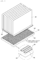
- FIGS. 1 to 3 are views illustrating a structure for explaining a battery module according to one embodiment of the present disclosure.
- a battery module is characterized by including a cell cover 30 close to a battery cell 10 and having one surface emitting heat of the battery cell 10; and a cooling channel portion 50 having a cooling channel 52 that a refrigerant flows formed therein and having one surface of the cooling channel 52 close to the one surface of the cell cover 30 to absorb heat of the battery cell 10, wherein in a contact region of the cell cover 30 and the cooling channel portion 50, the cell cover 30 has a protrusion portion 32 protruded in the direction of the cooling channel 52; and the cooling channel 52 has a penetration hole for inserting the protrusion portion 32 into an inner portion that the refrigerant flows.
- the battery cell 10 has a structure that is received within the cell cover 30 and stacked at constant intervals.
- a lower surface of the cell cover 30 has the protrusion portion 32 protruding in the direction of the cooling channel 52; and a shape of the protrusion portion 32 may be a shape bent as U or V, as one embodiment of the present disclosure. That is, as shown in FIG. 1 , the lower surface of the cell cover 30 may be a shape bent as U or a V-acicular shape. As not shown in the figure, however, the protrusion portion 32 may have a rod-shaped structure as another embodiment.
- the protrusion portion 32 of the cell cover 30 according to various embodiments is inserted into the cooling channel 52 to directly contact with a refrigerant, thereby efficiently emitting heat that generates in the battery cell 10.
- the refrigerant includes cold water or cooling water.
- the cooling channel portion 50 may have the penetration hole into which the protrusion portion 32 of the cell cover 30 may be inserted; and the penetration hole may have a diameter of degree into which the protrusion portion 32 of the cell cover 30 may be inserted.
- the foregoing is intended to compress and couple the cell cover 30 and the cooling channel portion 50 together with a gasket 70 as will be described later, thereby preventing leakage of the refrigerant.
- the structure of the cell cover 30 having the protrusion portion 32 and the cooling channel portion 50 having the penetration hole of the present disclosure in the case that surface roughness or processing flatness of a contact surface of the water cooling plate that was a problem in the related art is not good, it is possible to resolve reduction of a contact resistance generated by non-uniform contact and inner bubbles between the cell cover and an interfacial thermal contact material and between the interfacial thermal contact material and the water cooling plate; to enhance assembly productivity due to removal of the interfacial thermal contact material; and to save manufacturing costs.
- a battery module may include a cell cover 30 having an upper surface, a side surface, and a lower surface formed to receive a battery cell 10 and having a protrusion portion 32 formed on the lower surface thereof; a cooling channel portion 50 having a cooling channel 52 that a refrigerant flows formed therein and having a penetration hole into which the protrusion portion 32 of the cell cover 30 is inserted formed on one surface of the cooling channel 52; and a gasket 70 positioned along a circumference of the penetration hole of the cooling channel portion 50.
- the upper surface of the cell cover 30 is not shown in the figure, but may include the upper surface as shown in FIG. 1 .
- the cell cover 30 has an inner space with the upper surface, the side surface, and the lower surface formed to receive the battery cell 10; and in FIG. 2 , the portion spaced between the cell covers 30, as the portion for making a single cell cover 30 to bond therebetween in a manufacturing process, may be bonded to complete an assembly of one cell cover 30.
- the lower surface of the cell cover 30 has one side portion forming the protrusion portion 32 and inserted into the penetration hole of the cooling channel portion 50 to directly contact with the refrigerant; and has the other side portion 34 contacting with an outer surface of the cooling channel portion 50.
- the gasket 70 as a sealing gasket for watertight, is compressed and interposed between the other side portion 34 of the cell cover 30 and the outer surface of the cooling channel portion 50 along a circumference of the penetration hole of the cooling channel portion 50, thereby preventing leakage of cooling water when the cell cover 30 and the cooling channel portion 50 are coupled.
- a material of the gasket 70 may be an elastic material.
- a battery module may include a cell cover 30 having an upper surface, a lower surface, and a side surface formed to receive a plurality of battery cells, having a wall interposed between the battery cells, and having a plurality of protrusion portions 32 formed on the lower surface thereof; and a cooling channel portion 50 having a plurality of cooling channels 52 that a refrigerant flows formed therein and having a penetration hole into which the protrusion portion 32 of the cell cover 30 is inserted formed on one surface of each of the cooling channels 52.
- the upper surface of the cell cover 30 is not shown in the figure, but may include the upper surface as shown in FIG. 1 .
- the cell cover 30, as an assembly of the cell cover capable of receiving a plurality of battery cells, has a plurality of protrusion portions 32 formed on the lower surface; and the protrusion portion 32, as one embodiment of the present disclosure, has a structure bent as U or V and is inserted into the penetration hole of the cooling channel portion 50 to directly contact with the refrigerant.
- the cooling channel portion 50 may have a plurality of penetration holes into which the protrusion portion 32 of the cell cover 30 is inserted; and the penetration hole may have a diameter of degree into which the protrusion portion 32 of the cell cover 30 may be inserted.
- the foregoing is intended to compress and couple the cell cover 30 and the cooling channel portion 50 together with the gasket 70 to form a watertight structure, thereby preventing leakage of the refrigerant within the cooling channel 52.
- the gasket 70 may be positioned along a circumference of each of the penetration holes of the cooling channel portion 50.
- the cell cover 30, the gasket 70, and the cooling channel portion 50 are assembled in the direction from the cell cover 30 to the cooling channel portion 50 and then compressed and coupled to form a watertight structure capable of preventing leakage of the refrigerant of the cooling channel 52.
- a battery module may improve a structure of a water cooling system for controlling heat that generates in a battery module within a battery system, thereby enhancing thermal transfer efficiency.
Landscapes
- Chemical & Material Sciences (AREA)
- Chemical Kinetics & Catalysis (AREA)
- Electrochemistry (AREA)
- General Chemical & Material Sciences (AREA)
- Engineering & Computer Science (AREA)
- Manufacturing & Machinery (AREA)
- Battery Mounting, Suspending (AREA)
- Secondary Cells (AREA)
Abstract
Description
- The present disclosure relates to a battery module, and more particularly, to a battery module for improving a structure of a water cooling system for controlling heat that generates in the battery module within a battery system, thereby enhancing thermal transfer efficiency.
- An eco-friendly vehicle such as a hybrid vehicle and an electric vehicle and the like is mounted with a high-voltage battery capable of storing an electric energy and a cooling system for cooling a battery module within the high-voltage battery.
- A battery system indirectly cools a battery cell using a water cooling plate constituting a cooling channel, instead of a direct contact method, in order to obtain an electrical insulation between the battery cell and cooling water.
- In the related art, an interfacial thermal contact material interposed between the water cooling plate and a cell cover is applied to reduce a contact thermal resistance between the water cooling plate and the cell cover. However, in the case that surface roughness or processing flatness of a contact surface of the water cooling plate is not good, there has been a problem that inner bubbles occur due to non-uniform contact, thereby greatly occurring a contact thermal resistance between the water cooling plate and the cell cover.
- Accordingly, there was a need for a solution enhancing thermal transfer efficiency between the water cooling plate and the cell cover and enhancing assembly productivity.
- The foregoing is intended merely to aid in the understanding of the background of the present disclosure, and is not intended to mean that the present disclosure falls within the purview of the related art that is already known to those skilled in the art.
- The present disclosure is proposed for solving the above problems, and the present disclosure is intended to provide a battery module improving a structure of a water cooling system for controlling heat that generates in the battery module within a battery system, thereby enhancing thermal transfer efficiency.
- A battery module according to the present disclosure for achieving the object is characterized by including a cell cover close to a battery cell and having one surface emitting heat of the battery cell; and a cooling channel portion having a cooling channel that a refrigerant flows formed therein and having one surface of the cooling channel close to the one surface of the cell cover to absorb heat of the battery cell, wherein in a contact region of the cell cover and the cooling channel portion, the cell cover has a protrusion portion protruded in the direction of the cooling channel and the cooling channel has a penetration hole for inserting the protrusion portion into an inner portion that the refrigerant flows.
- The protrusion portion of the cell cover is characterized by having a structure bent as U or V and being inserted into the penetration hole to directly contact with the refrigerant.
- The battery module is characterized by further including a gasket positioned along a circumference of the penetration hole of the cooling channel portion, wherein the gasket is compressed by contact of the cell cover and the cooling channel portion.
- A battery module according to the present disclosure includes a cell cover having an upper surface, a side surface, and a lower surface formed to receive a battery cell and having a protrusion portion formed on the lower surface thereof; a cooling channel portion having a cooling channel that a refrigerant flows formed therein and having a penetration hole into which the protrusion portion of the cell cover is inserted formed on one surface of the cooling channel; and a gasket positioned along a circumference of the penetration hole of the cooling channel portion.
- The lower surface of the cell cover is characterized by having one side portion forming the protrusion portion and inserted into the penetration hole of the cooling channel portion to directly contact with the refrigerant and having the other side portion contacting an outer surface of the cooling channel portion; and the gasket is characterized by being interposed and compressed between the other side portion of the cell cover and the outer surface of the cooling channel portion.
- The protrusion portion is characterized by having a structure bent as U or V.
- A battery module according to the present disclosure includes a cell cover having an upper surface, a lower surface, and a side surface formed to receive a plurality of battery cells, having a wall interposed between the battery cells, and having a plurality of protrusion portions formed on the lower surface thereof; and a cooling channel portion having a plurality of cooling channels that a refrigerant flows formed therein and having a penetration hole into which the protrusion portion of the cell cover is inserted formed on one surface of each of the cooling channels.
- The protrusion portion of the cell cover is characterized by having a structure bent as U or V and being inserted into the penetration hole to directly contact with the refrigerant.
- The battery module is characterized by further including a plurality of gaskets positioned along a circumference of each of the penetration holes of the cooling channel portion; and the gasket is characterized by being compressed by contact of the cell cover and the cooling channel portion.
- According to the battery module of the present disclosure, it is possible to improve a structure of a water cooling system for controlling heat that generates in the battery module within a battery system, thereby enhancing thermal transfer efficiency.
- Further, it is possible to reduce power consumption by an air-conditioning load through the improvement of thermal transfer efficiency.
- Further, it is possible to remove an interfacial thermal contact material between the water cooling plate and the cell cover, thereby enhancing assembly productivity and saving manufacturing costs.
- The above and other objects, features and other advantages of the present disclosure will be more clearly understood from the following detailed description when taken in conjunction with the accompanying drawings, in which:
-
FIGS. 1 to 3 are views illustrating a structure for explaining a battery module according to one embodiment of the present disclosure. - Hereinbelow, a battery module according to various embodiments of the present disclosure will be described in detail with reference to the accompanying drawings.
-
FIGS. 1 to 3 are views illustrating a structure for explaining a battery module according to one embodiment of the present disclosure. - First, referring to
FIG. 1 , a battery module according to one embodiment of the present disclosure is characterized by including acell cover 30 close to abattery cell 10 and having one surface emitting heat of thebattery cell 10; and acooling channel portion 50 having acooling channel 52 that a refrigerant flows formed therein and having one surface of thecooling channel 52 close to the one surface of thecell cover 30 to absorb heat of thebattery cell 10, wherein in a contact region of thecell cover 30 and thecooling channel portion 50, thecell cover 30 has aprotrusion portion 32 protruded in the direction of thecooling channel 52; and thecooling channel 52 has a penetration hole for inserting theprotrusion portion 32 into an inner portion that the refrigerant flows. - Herein, the
battery cell 10 has a structure that is received within thecell cover 30 and stacked at constant intervals. - A lower surface of the
cell cover 30 has theprotrusion portion 32 protruding in the direction of thecooling channel 52; and a shape of theprotrusion portion 32 may be a shape bent as U or V, as one embodiment of the present disclosure. That is, as shown inFIG. 1 , the lower surface of thecell cover 30 may be a shape bent as U or a V-acicular shape. As not shown in the figure, however, theprotrusion portion 32 may have a rod-shaped structure as another embodiment. Theprotrusion portion 32 of thecell cover 30 according to various embodiments is inserted into thecooling channel 52 to directly contact with a refrigerant, thereby efficiently emitting heat that generates in thebattery cell 10. Herein, the refrigerant includes cold water or cooling water. - The
cooling channel portion 50 may have the penetration hole into which theprotrusion portion 32 of thecell cover 30 may be inserted; and the penetration hole may have a diameter of degree into which theprotrusion portion 32 of thecell cover 30 may be inserted. The foregoing is intended to compress and couple thecell cover 30 and thecooling channel portion 50 together with agasket 70 as will be described later, thereby preventing leakage of the refrigerant. - By means of the structure of the
cell cover 30 having theprotrusion portion 32 and thecooling channel portion 50 having the penetration hole of the present disclosure, in the case that surface roughness or processing flatness of a contact surface of the water cooling plate that was a problem in the related art is not good, it is possible to resolve reduction of a contact resistance generated by non-uniform contact and inner bubbles between the cell cover and an interfacial thermal contact material and between the interfacial thermal contact material and the water cooling plate; to enhance assembly productivity due to removal of the interfacial thermal contact material; and to save manufacturing costs. - Further, it is possible to perform a direct thermal exchange between the
cell cover 30 and the refrigerant of thecooling channel 52, thereby reducing a thermal resistance compared to the related art that applies an interfacial thermal contact material to a space between the cell cover and the cooling channel. - Referring to
FIG. 2 , a battery module according to one embodiment of the present disclosure may include acell cover 30 having an upper surface, a side surface, and a lower surface formed to receive abattery cell 10 and having aprotrusion portion 32 formed on the lower surface thereof; acooling channel portion 50 having acooling channel 52 that a refrigerant flows formed therein and having a penetration hole into which theprotrusion portion 32 of thecell cover 30 is inserted formed on one surface of thecooling channel 52; and agasket 70 positioned along a circumference of the penetration hole of thecooling channel portion 50. - Herein, the upper surface of the
cell cover 30 is not shown in the figure, but may include the upper surface as shown inFIG. 1 . - The
cell cover 30 has an inner space with the upper surface, the side surface, and the lower surface formed to receive thebattery cell 10; and inFIG. 2 , the portion spaced between the cell covers 30, as the portion for making asingle cell cover 30 to bond therebetween in a manufacturing process, may be bonded to complete an assembly of onecell cover 30. - The lower surface of the
cell cover 30 has one side portion forming theprotrusion portion 32 and inserted into the penetration hole of thecooling channel portion 50 to directly contact with the refrigerant; and has theother side portion 34 contacting with an outer surface of thecooling channel portion 50. - The
gasket 70, as a sealing gasket for watertight, is compressed and interposed between theother side portion 34 of thecell cover 30 and the outer surface of thecooling channel portion 50 along a circumference of the penetration hole of thecooling channel portion 50, thereby preventing leakage of cooling water when thecell cover 30 and thecooling channel portion 50 are coupled. A material of thegasket 70 may be an elastic material. - Referring to
FIG. 3 , a battery module according to one embodiment of the present disclosure may include acell cover 30 having an upper surface, a lower surface, and a side surface formed to receive a plurality of battery cells, having a wall interposed between the battery cells, and having a plurality ofprotrusion portions 32 formed on the lower surface thereof; and acooling channel portion 50 having a plurality ofcooling channels 52 that a refrigerant flows formed therein and having a penetration hole into which theprotrusion portion 32 of thecell cover 30 is inserted formed on one surface of each of thecooling channels 52. - Herein, the upper surface of the
cell cover 30 is not shown in the figure, but may include the upper surface as shown inFIG. 1 . - The cell cover 30, as an assembly of the cell cover capable of receiving a plurality of battery cells, has a plurality of
protrusion portions 32 formed on the lower surface; and theprotrusion portion 32, as one embodiment of the present disclosure, has a structure bent as U or V and is inserted into the penetration hole of thecooling channel portion 50 to directly contact with the refrigerant. - The
cooling channel portion 50 may have a plurality of penetration holes into which theprotrusion portion 32 of thecell cover 30 is inserted; and the penetration hole may have a diameter of degree into which theprotrusion portion 32 of thecell cover 30 may be inserted. As described above, the foregoing is intended to compress and couple thecell cover 30 and thecooling channel portion 50 together with thegasket 70 to form a watertight structure, thereby preventing leakage of the refrigerant within thecooling channel 52. - The
gasket 70 may be positioned along a circumference of each of the penetration holes of thecooling channel portion 50. - The
cell cover 30, thegasket 70, and thecooling channel portion 50 are assembled in the direction from thecell cover 30 to thecooling channel portion 50 and then compressed and coupled to form a watertight structure capable of preventing leakage of the refrigerant of thecooling channel 52. - As described above, a battery module according to various embodiments of the present disclosure may improve a structure of a water cooling system for controlling heat that generates in a battery module within a battery system, thereby enhancing thermal transfer efficiency.
- Further, it is possible to reduce power consumption by an air-conditioning load through the improvement of thermal transfer efficiency.
- Further, it is possible to remove an interfacial thermal contact material between a water cooling plate and a cell cover, thereby enhancing assembly productivity and saving manufacturing costs.
- Although an exemplary embodiment of the present disclosure has been described for illustrative purposes, those skilled in the art will appreciate that various modifications, additions and substitutions are possible, without departing from the scope and spirit of the invention as disclosed in the accompanying claims.
Claims (9)
- A battery module, comprising:a cell cover close to a battery cell and having one surface emitting heat of the battery cell; anda cooling channel portion having a cooling channel that a refrigerant flows formed therein and having one surface of the cooling channel close to the one surface of the cell cover to absorb heat of the battery cell,wherein in a contact region of the cell cover and the cooling channel portion, the cell cover has a protrusion portion protruded in the direction of the cooling channel, and the cooling channel has a penetration hole for inserting the protrusion portion into an inner portion that the refrigerant flows.
- The battery module according to claim 1, wherein the protrusion portion of the cell cover has a structure bent as U or V and is inserted into the penetration hole to directly contact with the refrigerant.
- The battery module according to claim 1 or 2, further comprising a gasket positioned along a circumference of the penetration hole of the cooling channel portion,
wherein the gasket is compressed by contact of the cell cover and the cooling channel portion. - A battery module, comprising:a cell cover having an upper surface, a side surface, and a lower surface receiving a battery cell and having a protrusion portion on the lower surface thereof;a cooling channel portion having a cooling channel that a refrigerant flows formed therein and having a penetration hole, into which the protrusion portion of the cell cover is inserted, formed on one surface of the cooling channel; anda gasket positioned along a circumference of the penetration hole of the cooling channel portion.
- The battery module according to claim 4, wherein the lower surface of the cell cover has one side portion forming the protrusion portion and inserted into the penetration hole of the cooling channel portion to directly contact with the refrigerant and has another side portion contacting with an outer surface of the cooling channel portion, and
wherein the gasket is interposed and compressed between the other side portion of the cell cover and the outer surface of the cooling channel portion. - The battery module according to claim 4 or 5, wherein the protrusion portion has a structure bent as U or V.
- A battery module, comprising:a cell cover having an upper surface, a lower surface, and a side surface receiving a plurality of battery cells, having a wall interposed between the battery cells, and having a plurality of protrusion portions on the lower surface; anda cooling channel portion having a plurality of cooling channels that a refrigerant flows formed therein and having a penetration hole, into which the protrusion portion of the cell cover is inserted, on one surface of each of the cooling channels.
- The battery module according to claim 7, wherein the protrusion portion of the cell cover has a structure bent as U or V and is inserted into the penetration hole to directly contact with the refrigerant.
- The battery module according to claim 7 or 8, further comprising a plurality of gaskets disposed along a circumference of each of the penetration holes of the cooling channel portion,
wherein the gasket is compressed by contact of the cell cover and the cooling channel portion.
Applications Claiming Priority (1)
| Application Number | Priority Date | Filing Date | Title |
|---|---|---|---|
| KR1020170102413A KR102410517B1 (en) | 2017-08-11 | 2017-08-11 | Battery module |
Publications (2)
| Publication Number | Publication Date |
|---|---|
| EP3442049A1 true EP3442049A1 (en) | 2019-02-13 |
| EP3442049B1 EP3442049B1 (en) | 2023-08-02 |
Family
ID=60569786
Family Applications (1)
| Application Number | Title | Priority Date | Filing Date |
|---|---|---|---|
| EP17205132.8A Active EP3442049B1 (en) | 2017-08-11 | 2017-12-04 | Battery module |
Country Status (4)
| Country | Link |
|---|---|
| US (1) | US10790558B2 (en) |
| EP (1) | EP3442049B1 (en) |
| KR (1) | KR102410517B1 (en) |
| CN (1) | CN109390502B (en) |
Families Citing this family (4)
| Publication number | Priority date | Publication date | Assignee | Title |
|---|---|---|---|---|
| US11799149B2 (en) * | 2020-08-26 | 2023-10-24 | GM Global Technology Operations LLC | Energy storage assembly |
| KR102789263B1 (en) | 2020-10-16 | 2025-03-28 | 주식회사 엘지에너지솔루션 | Battery pack and vehicle comprising the same |
| US11581618B2 (en) | 2020-11-18 | 2023-02-14 | GM Global Technology Operations LLC | Thermomechanical fuses for heat propagation mitigation of electrochemical devices |
| CN117559028A (en) * | 2022-08-04 | 2024-02-13 | 本田技研工业(中国)投资有限公司 | A battery pack and vehicle |
Citations (4)
| Publication number | Priority date | Publication date | Assignee | Title |
|---|---|---|---|---|
| US20110104545A1 (en) * | 2007-08-06 | 2011-05-05 | Daimler Ag | Battery, Particularly for a Hybrid Drive |
| US20110244299A1 (en) * | 2008-12-10 | 2011-10-06 | Nevzat Guener | Energy Store |
| JP2013051099A (en) * | 2011-08-31 | 2013-03-14 | Nissan Motor Co Ltd | Module for battery temperature control |
| WO2014036227A1 (en) * | 2012-08-31 | 2014-03-06 | Avl Test Systems Inc. | High power battery cells having improved cooling |
Family Cites Families (15)
| Publication number | Priority date | Publication date | Assignee | Title |
|---|---|---|---|---|
| JP3451142B2 (en) * | 1994-11-18 | 2003-09-29 | 本田技研工業株式会社 | Battery assembly with temperature control mechanism |
| JP2009079505A (en) * | 2007-09-25 | 2009-04-16 | Toyota Motor Corp | Engine cooling device and vehicle |
| US8465863B2 (en) * | 2008-04-09 | 2013-06-18 | GM Global Technology Operations LLC | Batteries and components thereof and methods of making and assembling the same |
| US8852778B2 (en) * | 2009-04-30 | 2014-10-07 | Lg Chem, Ltd. | Battery systems, battery modules, and method for cooling a battery module |
| US8399118B2 (en) * | 2009-07-29 | 2013-03-19 | Lg Chem, Ltd. | Battery module and method for cooling the battery module |
| DE102009040147A1 (en) * | 2009-09-04 | 2011-03-10 | Li-Tec Battery Gmbh | Electrochemical energy storage device for vehicles and method for cooling or heating such an electrochemical energy storage device |
| KR20110026193A (en) * | 2009-09-07 | 2011-03-15 | 삼성전자주식회사 | Heating element cooling system and battery cooling system |
| KR101218751B1 (en) * | 2010-01-06 | 2013-01-07 | 주식회사 엘지화학 | Middle or Large-sized Battery Pack of Improved Cooling Efficiency |
| DE102010012934A1 (en) * | 2010-03-26 | 2011-09-29 | Daimler Ag | Single cell and battery with a plurality of single cells |
| US20120088140A1 (en) * | 2010-10-08 | 2012-04-12 | Kardasz Grzegorz M | Battery having internal electrolyte flow path and/or integral heat sink |
| US9444124B2 (en) * | 2014-01-23 | 2016-09-13 | Lg Chem, Ltd. | Battery cell assembly and method for coupling a cooling fin to first and second cooling manifolds |
| KR102329216B1 (en) | 2014-08-25 | 2021-11-22 | 현대자동차주식회사 | Battery cooling device for vehicles |
| KR101780037B1 (en) * | 2015-04-22 | 2017-09-19 | 주식회사 엘지화학 | Cooling device for battery cell and battery module comprising the same |
| KR102025861B1 (en) * | 2015-06-15 | 2019-09-26 | 주식회사 엘지화학 | Cooling Apparatus for Battery Cell |
| KR102519046B1 (en) * | 2015-10-05 | 2023-04-06 | 현대모비스 주식회사 | apparatus for controlling temperature of coolant of battery system cooled by water and method thereof |
-
2017
- 2017-08-11 KR KR1020170102413A patent/KR102410517B1/en active Active
- 2017-12-04 EP EP17205132.8A patent/EP3442049B1/en active Active
- 2017-12-04 US US15/830,944 patent/US10790558B2/en active Active
- 2017-12-05 CN CN201711280684.5A patent/CN109390502B/en active Active
Patent Citations (4)
| Publication number | Priority date | Publication date | Assignee | Title |
|---|---|---|---|---|
| US20110104545A1 (en) * | 2007-08-06 | 2011-05-05 | Daimler Ag | Battery, Particularly for a Hybrid Drive |
| US20110244299A1 (en) * | 2008-12-10 | 2011-10-06 | Nevzat Guener | Energy Store |
| JP2013051099A (en) * | 2011-08-31 | 2013-03-14 | Nissan Motor Co Ltd | Module for battery temperature control |
| WO2014036227A1 (en) * | 2012-08-31 | 2014-03-06 | Avl Test Systems Inc. | High power battery cells having improved cooling |
Also Published As
| Publication number | Publication date |
|---|---|
| KR102410517B1 (en) | 2022-06-20 |
| US10790558B2 (en) | 2020-09-29 |
| EP3442049B1 (en) | 2023-08-02 |
| US20190051956A1 (en) | 2019-02-14 |
| CN109390502B (en) | 2022-07-29 |
| KR20190018107A (en) | 2019-02-21 |
| CN109390502A (en) | 2019-02-26 |
Similar Documents
| Publication | Publication Date | Title |
|---|---|---|
| US10790558B2 (en) | Battery module | |
| KR102403695B1 (en) | Rechargeable battery and module thereof | |
| US10601091B2 (en) | Rechargeable battery module | |
| US9070939B2 (en) | Battery module | |
| KR101840417B1 (en) | Battery Module Comprising Cooling Structure having Minimized Bending of Coolant Channel | |
| EP2654101B1 (en) | Battery pack | |
| CN102142575B (en) | Battery cell module | |
| US10886510B2 (en) | Battery module with selective temperature control | |
| KR102740793B1 (en) | Temperature control module and battery pack | |
| CN108631022B (en) | Battery module with improved cooling performance | |
| KR20060102851A (en) | Secondary battery module | |
| KR20100065669A (en) | Rechargeable battery and battery module using thereof | |
| EP3930025B1 (en) | Battery module, battery pack, and vehicle | |
| EP3136593B1 (en) | Photovoltaic junction box | |
| KR102788863B1 (en) | Battery module | |
| EP3480883A1 (en) | Battery-cooling heat exchanger | |
| KR20190054300A (en) | Battery | |
| US20230006278A1 (en) | Secondary Battery and Battery Module Having Thereof | |
| KR20190046526A (en) | Heat Pipe For Battery Cooling | |
| KR20170103238A (en) | Battery pack case improved in coolong performance | |
| US20240204300A1 (en) | Power storage device | |
| KR102028916B1 (en) | Battery Pack for Secondary Battery | |
| CN120149686A (en) | Battery pack and electrical equipment | |
| KR102063521B1 (en) | Battery Pack | |
| KR200464432Y1 (en) | Secondary battery module containing heat plate of effective temperature control |
Legal Events
| Date | Code | Title | Description |
|---|---|---|---|
| PUAI | Public reference made under article 153(3) epc to a published international application that has entered the european phase |
Free format text: ORIGINAL CODE: 0009012 |
|
| STAA | Information on the status of an ep patent application or granted ep patent |
Free format text: STATUS: THE APPLICATION HAS BEEN PUBLISHED |
|
| AK | Designated contracting states |
Kind code of ref document: A1 Designated state(s): AL AT BE BG CH CY CZ DE DK EE ES FI FR GB GR HR HU IE IS IT LI LT LU LV MC MK MT NL NO PL PT RO RS SE SI SK SM TR |
|
| AX | Request for extension of the european patent |
Extension state: BA ME |
|
| STAA | Information on the status of an ep patent application or granted ep patent |
Free format text: STATUS: REQUEST FOR EXAMINATION WAS MADE |
|
| 17P | Request for examination filed |
Effective date: 20190812 |
|
| RBV | Designated contracting states (corrected) |
Designated state(s): AL AT BE BG CH CY CZ DE DK EE ES FI FR GB GR HR HU IE IS IT LI LT LU LV MC MK MT NL NO PL PT RO RS SE SI SK SM TR |
|
| STAA | Information on the status of an ep patent application or granted ep patent |
Free format text: STATUS: EXAMINATION IS IN PROGRESS |
|
| 17Q | First examination report despatched |
Effective date: 20200218 |
|
| RAP3 | Party data changed (applicant data changed or rights of an application transferred) |
Owner name: HYUNDAI MOTOR COMPANY Owner name: KIA CORPORATION |
|
| REG | Reference to a national code |
Ref country code: DE Ref legal event code: R079 Free format text: PREVIOUS MAIN CLASS: H01M0002100000 Ipc: H01M0050103000 Ref document number: 602017072069 Country of ref document: DE |
|
| GRAP | Despatch of communication of intention to grant a patent |
Free format text: ORIGINAL CODE: EPIDOSNIGR1 |
|
| STAA | Information on the status of an ep patent application or granted ep patent |
Free format text: STATUS: GRANT OF PATENT IS INTENDED |
|
| RIC1 | Information provided on ipc code assigned before grant |
Ipc: H01M 50/271 20210101ALI20230214BHEP Ipc: H01M 50/211 20210101ALI20230214BHEP Ipc: H01M 10/6555 20140101ALI20230214BHEP Ipc: H01M 10/625 20140101ALI20230214BHEP Ipc: H01M 10/6556 20140101ALI20230214BHEP Ipc: H01M 10/6568 20140101ALI20230214BHEP Ipc: H01M 10/6551 20140101ALI20230214BHEP Ipc: H01M 10/653 20140101ALI20230214BHEP Ipc: H01M 10/647 20140101ALI20230214BHEP Ipc: H01M 10/613 20140101ALI20230214BHEP Ipc: H01M 50/183 20210101ALI20230214BHEP Ipc: H01M 50/103 20210101AFI20230214BHEP |
|
| INTG | Intention to grant announced |
Effective date: 20230228 |
|
| P01 | Opt-out of the competence of the unified patent court (upc) registered |
Effective date: 20230505 |
|
| GRAS | Grant fee paid |
Free format text: ORIGINAL CODE: EPIDOSNIGR3 |
|
| GRAA | (expected) grant |
Free format text: ORIGINAL CODE: 0009210 |
|
| STAA | Information on the status of an ep patent application or granted ep patent |
Free format text: STATUS: THE PATENT HAS BEEN GRANTED |
|
| AK | Designated contracting states |
Kind code of ref document: B1 Designated state(s): AL AT BE BG CH CY CZ DE DK EE ES FI FR GB GR HR HU IE IS IT LI LT LU LV MC MK MT NL NO PL PT RO RS SE SI SK SM TR |
|
| REG | Reference to a national code |
Ref country code: GB Ref legal event code: FG4D |
|
| REG | Reference to a national code |
Ref country code: CH Ref legal event code: EP |
|
| REG | Reference to a national code |
Ref country code: DE Ref legal event code: R096 Ref document number: 602017072069 Country of ref document: DE |
|
| REG | Reference to a national code |
Ref country code: IE Ref legal event code: FG4D |
|
| REG | Reference to a national code |
Ref country code: LT Ref legal event code: MG9D |
|
| REG | Reference to a national code |
Ref country code: NL Ref legal event code: MP Effective date: 20230802 |
|
| REG | Reference to a national code |
Ref country code: AT Ref legal event code: MK05 Ref document number: 1595847 Country of ref document: AT Kind code of ref document: T Effective date: 20230802 |
|
| PG25 | Lapsed in a contracting state [announced via postgrant information from national office to epo] |
Ref country code: GR Free format text: LAPSE BECAUSE OF FAILURE TO SUBMIT A TRANSLATION OF THE DESCRIPTION OR TO PAY THE FEE WITHIN THE PRESCRIBED TIME-LIMIT Effective date: 20231103 |
|
| PG25 | Lapsed in a contracting state [announced via postgrant information from national office to epo] |
Ref country code: IS Free format text: LAPSE BECAUSE OF FAILURE TO SUBMIT A TRANSLATION OF THE DESCRIPTION OR TO PAY THE FEE WITHIN THE PRESCRIBED TIME-LIMIT Effective date: 20231202 |
|
| PG25 | Lapsed in a contracting state [announced via postgrant information from national office to epo] |
Ref country code: SE Free format text: LAPSE BECAUSE OF FAILURE TO SUBMIT A TRANSLATION OF THE DESCRIPTION OR TO PAY THE FEE WITHIN THE PRESCRIBED TIME-LIMIT Effective date: 20230802 Ref country code: RS Free format text: LAPSE BECAUSE OF FAILURE TO SUBMIT A TRANSLATION OF THE DESCRIPTION OR TO PAY THE FEE WITHIN THE PRESCRIBED TIME-LIMIT Effective date: 20230802 Ref country code: PT Free format text: LAPSE BECAUSE OF FAILURE TO SUBMIT A TRANSLATION OF THE DESCRIPTION OR TO PAY THE FEE WITHIN THE PRESCRIBED TIME-LIMIT Effective date: 20231204 Ref country code: NO Free format text: LAPSE BECAUSE OF FAILURE TO SUBMIT A TRANSLATION OF THE DESCRIPTION OR TO PAY THE FEE WITHIN THE PRESCRIBED TIME-LIMIT Effective date: 20231102 Ref country code: NL Free format text: LAPSE BECAUSE OF FAILURE TO SUBMIT A TRANSLATION OF THE DESCRIPTION OR TO PAY THE FEE WITHIN THE PRESCRIBED TIME-LIMIT Effective date: 20230802 Ref country code: LV Free format text: LAPSE BECAUSE OF FAILURE TO SUBMIT A TRANSLATION OF THE DESCRIPTION OR TO PAY THE FEE WITHIN THE PRESCRIBED TIME-LIMIT Effective date: 20230802 Ref country code: LT Free format text: LAPSE BECAUSE OF FAILURE TO SUBMIT A TRANSLATION OF THE DESCRIPTION OR TO PAY THE FEE WITHIN THE PRESCRIBED TIME-LIMIT Effective date: 20230802 Ref country code: IS Free format text: LAPSE BECAUSE OF FAILURE TO SUBMIT A TRANSLATION OF THE DESCRIPTION OR TO PAY THE FEE WITHIN THE PRESCRIBED TIME-LIMIT Effective date: 20231202 Ref country code: HR Free format text: LAPSE BECAUSE OF FAILURE TO SUBMIT A TRANSLATION OF THE DESCRIPTION OR TO PAY THE FEE WITHIN THE PRESCRIBED TIME-LIMIT Effective date: 20230802 Ref country code: GR Free format text: LAPSE BECAUSE OF FAILURE TO SUBMIT A TRANSLATION OF THE DESCRIPTION OR TO PAY THE FEE WITHIN THE PRESCRIBED TIME-LIMIT Effective date: 20231103 Ref country code: FI Free format text: LAPSE BECAUSE OF FAILURE TO SUBMIT A TRANSLATION OF THE DESCRIPTION OR TO PAY THE FEE WITHIN THE PRESCRIBED TIME-LIMIT Effective date: 20230802 Ref country code: AT Free format text: LAPSE BECAUSE OF FAILURE TO SUBMIT A TRANSLATION OF THE DESCRIPTION OR TO PAY THE FEE WITHIN THE PRESCRIBED TIME-LIMIT Effective date: 20230802 |
|
| PG25 | Lapsed in a contracting state [announced via postgrant information from national office to epo] |
Ref country code: PL Free format text: LAPSE BECAUSE OF FAILURE TO SUBMIT A TRANSLATION OF THE DESCRIPTION OR TO PAY THE FEE WITHIN THE PRESCRIBED TIME-LIMIT Effective date: 20230802 |
|
| PG25 | Lapsed in a contracting state [announced via postgrant information from national office to epo] |
Ref country code: ES Free format text: LAPSE BECAUSE OF FAILURE TO SUBMIT A TRANSLATION OF THE DESCRIPTION OR TO PAY THE FEE WITHIN THE PRESCRIBED TIME-LIMIT Effective date: 20230802 |
|
| PG25 | Lapsed in a contracting state [announced via postgrant information from national office to epo] |
Ref country code: SM Free format text: LAPSE BECAUSE OF FAILURE TO SUBMIT A TRANSLATION OF THE DESCRIPTION OR TO PAY THE FEE WITHIN THE PRESCRIBED TIME-LIMIT Effective date: 20230802 Ref country code: RO Free format text: LAPSE BECAUSE OF FAILURE TO SUBMIT A TRANSLATION OF THE DESCRIPTION OR TO PAY THE FEE WITHIN THE PRESCRIBED TIME-LIMIT Effective date: 20230802 Ref country code: ES Free format text: LAPSE BECAUSE OF FAILURE TO SUBMIT A TRANSLATION OF THE DESCRIPTION OR TO PAY THE FEE WITHIN THE PRESCRIBED TIME-LIMIT Effective date: 20230802 Ref country code: EE Free format text: LAPSE BECAUSE OF FAILURE TO SUBMIT A TRANSLATION OF THE DESCRIPTION OR TO PAY THE FEE WITHIN THE PRESCRIBED TIME-LIMIT Effective date: 20230802 Ref country code: DK Free format text: LAPSE BECAUSE OF FAILURE TO SUBMIT A TRANSLATION OF THE DESCRIPTION OR TO PAY THE FEE WITHIN THE PRESCRIBED TIME-LIMIT Effective date: 20230802 Ref country code: CZ Free format text: LAPSE BECAUSE OF FAILURE TO SUBMIT A TRANSLATION OF THE DESCRIPTION OR TO PAY THE FEE WITHIN THE PRESCRIBED TIME-LIMIT Effective date: 20230802 Ref country code: SK Free format text: LAPSE BECAUSE OF FAILURE TO SUBMIT A TRANSLATION OF THE DESCRIPTION OR TO PAY THE FEE WITHIN THE PRESCRIBED TIME-LIMIT Effective date: 20230802 |
|
| REG | Reference to a national code |
Ref country code: DE Ref legal event code: R097 Ref document number: 602017072069 Country of ref document: DE |
|
| PG25 | Lapsed in a contracting state [announced via postgrant information from national office to epo] |
Ref country code: IT Free format text: LAPSE BECAUSE OF FAILURE TO SUBMIT A TRANSLATION OF THE DESCRIPTION OR TO PAY THE FEE WITHIN THE PRESCRIBED TIME-LIMIT Effective date: 20230802 |
|
| PLBE | No opposition filed within time limit |
Free format text: ORIGINAL CODE: 0009261 |
|
| STAA | Information on the status of an ep patent application or granted ep patent |
Free format text: STATUS: NO OPPOSITION FILED WITHIN TIME LIMIT |
|
| 26N | No opposition filed |
Effective date: 20240503 |
|
| PG25 | Lapsed in a contracting state [announced via postgrant information from national office to epo] |
Ref country code: SI Free format text: LAPSE BECAUSE OF FAILURE TO SUBMIT A TRANSLATION OF THE DESCRIPTION OR TO PAY THE FEE WITHIN THE PRESCRIBED TIME-LIMIT Effective date: 20230802 |
|
| REG | Reference to a national code |
Ref country code: CH Ref legal event code: PL |
|
| PG25 | Lapsed in a contracting state [announced via postgrant information from national office to epo] |
Ref country code: LU Free format text: LAPSE BECAUSE OF NON-PAYMENT OF DUE FEES Effective date: 20231204 |
|
| PG25 | Lapsed in a contracting state [announced via postgrant information from national office to epo] |
Ref country code: MC Free format text: LAPSE BECAUSE OF FAILURE TO SUBMIT A TRANSLATION OF THE DESCRIPTION OR TO PAY THE FEE WITHIN THE PRESCRIBED TIME-LIMIT Effective date: 20230802 |
|
| REG | Reference to a national code |
Ref country code: BE Ref legal event code: MM Effective date: 20231231 |
|
| PG25 | Lapsed in a contracting state [announced via postgrant information from national office to epo] |
Ref country code: MC Free format text: LAPSE BECAUSE OF FAILURE TO SUBMIT A TRANSLATION OF THE DESCRIPTION OR TO PAY THE FEE WITHIN THE PRESCRIBED TIME-LIMIT Effective date: 20230802 Ref country code: LU Free format text: LAPSE BECAUSE OF NON-PAYMENT OF DUE FEES Effective date: 20231204 |
|
| REG | Reference to a national code |
Ref country code: IE Ref legal event code: MM4A |
|
| PG25 | Lapsed in a contracting state [announced via postgrant information from national office to epo] |
Ref country code: IE Free format text: LAPSE BECAUSE OF NON-PAYMENT OF DUE FEES Effective date: 20231204 |
|
| PG25 | Lapsed in a contracting state [announced via postgrant information from national office to epo] |
Ref country code: BE Free format text: LAPSE BECAUSE OF NON-PAYMENT OF DUE FEES Effective date: 20231231 |
|
| PG25 | Lapsed in a contracting state [announced via postgrant information from national office to epo] |
Ref country code: CH Free format text: LAPSE BECAUSE OF NON-PAYMENT OF DUE FEES Effective date: 20231231 |
|
| PG25 | Lapsed in a contracting state [announced via postgrant information from national office to epo] |
Ref country code: IE Free format text: LAPSE BECAUSE OF NON-PAYMENT OF DUE FEES Effective date: 20231204 Ref country code: CH Free format text: LAPSE BECAUSE OF NON-PAYMENT OF DUE FEES Effective date: 20231231 Ref country code: BE Free format text: LAPSE BECAUSE OF NON-PAYMENT OF DUE FEES Effective date: 20231231 |
|
| PG25 | Lapsed in a contracting state [announced via postgrant information from national office to epo] |
Ref country code: BG Free format text: LAPSE BECAUSE OF FAILURE TO SUBMIT A TRANSLATION OF THE DESCRIPTION OR TO PAY THE FEE WITHIN THE PRESCRIBED TIME-LIMIT Effective date: 20230802 |
|
| PG25 | Lapsed in a contracting state [announced via postgrant information from national office to epo] |
Ref country code: BG Free format text: LAPSE BECAUSE OF FAILURE TO SUBMIT A TRANSLATION OF THE DESCRIPTION OR TO PAY THE FEE WITHIN THE PRESCRIBED TIME-LIMIT Effective date: 20230802 |
|
| PG25 | Lapsed in a contracting state [announced via postgrant information from national office to epo] |
Ref country code: CY Free format text: LAPSE BECAUSE OF FAILURE TO SUBMIT A TRANSLATION OF THE DESCRIPTION OR TO PAY THE FEE WITHIN THE PRESCRIBED TIME-LIMIT; INVALID AB INITIO Effective date: 20171204 |
|
| PG25 | Lapsed in a contracting state [announced via postgrant information from national office to epo] |
Ref country code: HU Free format text: LAPSE BECAUSE OF FAILURE TO SUBMIT A TRANSLATION OF THE DESCRIPTION OR TO PAY THE FEE WITHIN THE PRESCRIBED TIME-LIMIT; INVALID AB INITIO Effective date: 20171204 |
|
| PG25 | Lapsed in a contracting state [announced via postgrant information from national office to epo] |
Ref country code: TR Free format text: LAPSE BECAUSE OF FAILURE TO SUBMIT A TRANSLATION OF THE DESCRIPTION OR TO PAY THE FEE WITHIN THE PRESCRIBED TIME-LIMIT Effective date: 20230802 |
|
| PGFP | Annual fee paid to national office [announced via postgrant information from national office to epo] |
Ref country code: DE Payment date: 20251120 Year of fee payment: 9 |
|
| PGFP | Annual fee paid to national office [announced via postgrant information from national office to epo] |
Ref country code: GB Payment date: 20251120 Year of fee payment: 9 |
|
| PGFP | Annual fee paid to national office [announced via postgrant information from national office to epo] |
Ref country code: FR Payment date: 20251125 Year of fee payment: 9 |