EP3442026A1 - Gate for an enhancement-mode transistor - Google Patents
Gate for an enhancement-mode transistor Download PDFInfo
- Publication number
- EP3442026A1 EP3442026A1 EP17186014.1A EP17186014A EP3442026A1 EP 3442026 A1 EP3442026 A1 EP 3442026A1 EP 17186014 A EP17186014 A EP 17186014A EP 3442026 A1 EP3442026 A1 EP 3442026A1
- Authority
- EP
- European Patent Office
- Prior art keywords
- doped
- gate layer
- layer
- concentration
- atoms
- Prior art date
- Legal status (The legal status is an assumption and is not a legal conclusion. Google has not performed a legal analysis and makes no representation as to the accuracy of the status listed.)
- Granted
Links
Images

Classifications
-
- H—ELECTRICITY
- H10—SEMICONDUCTOR DEVICES; ELECTRIC SOLID-STATE DEVICES NOT OTHERWISE PROVIDED FOR
- H10D—INORGANIC ELECTRIC SEMICONDUCTOR DEVICES
- H10D30/00—Field-effect transistors [FET]
- H10D30/01—Manufacture or treatment
- H10D30/015—Manufacture or treatment of FETs having heterojunction interface channels or heterojunction gate electrodes, e.g. HEMT
-
- H—ELECTRICITY
- H10—SEMICONDUCTOR DEVICES; ELECTRIC SOLID-STATE DEVICES NOT OTHERWISE PROVIDED FOR
- H10D—INORGANIC ELECTRIC SEMICONDUCTOR DEVICES
- H10D30/00—Field-effect transistors [FET]
- H10D30/40—FETs having zero-dimensional [0D], one-dimensional [1D] or two-dimensional [2D] charge carrier gas channels
- H10D30/47—FETs having zero-dimensional [0D], one-dimensional [1D] or two-dimensional [2D] charge carrier gas channels having two-dimensional [2D] charge carrier gas channels, e.g. nanoribbon FETs or high electron mobility transistors [HEMT]
- H10D30/471—High electron mobility transistors [HEMT] or high hole mobility transistors [HHMT]
- H10D30/475—High electron mobility transistors [HEMT] or high hole mobility transistors [HHMT] having wider bandgap layer formed on top of lower bandgap active layer, e.g. undoped barrier HEMTs such as i-AlGaN/GaN HEMTs
-
- H—ELECTRICITY
- H10—SEMICONDUCTOR DEVICES; ELECTRIC SOLID-STATE DEVICES NOT OTHERWISE PROVIDED FOR
- H10D—INORGANIC ELECTRIC SEMICONDUCTOR DEVICES
- H10D62/00—Semiconductor bodies, or regions thereof, of devices having potential barriers
- H10D62/10—Shapes, relative sizes or dispositions of the regions of the semiconductor bodies; Shapes of the semiconductor bodies
- H10D62/17—Semiconductor regions connected to electrodes not carrying current to be rectified, amplified or switched, e.g. channel regions
- H10D62/343—Gate regions of field-effect devices having PN junction gates
-
- H—ELECTRICITY
- H10—SEMICONDUCTOR DEVICES; ELECTRIC SOLID-STATE DEVICES NOT OTHERWISE PROVIDED FOR
- H10D—INORGANIC ELECTRIC SEMICONDUCTOR DEVICES
- H10D62/00—Semiconductor bodies, or regions thereof, of devices having potential barriers
- H10D62/80—Semiconductor bodies, or regions thereof, of devices having potential barriers characterised by the materials
- H10D62/85—Semiconductor bodies, or regions thereof, of devices having potential barriers characterised by the materials being Group III-V materials, e.g. GaAs
- H10D62/8503—Nitride Group III-V materials, e.g. AlN or GaN
-
- H—ELECTRICITY
- H10—SEMICONDUCTOR DEVICES; ELECTRIC SOLID-STATE DEVICES NOT OTHERWISE PROVIDED FOR
- H10D—INORGANIC ELECTRIC SEMICONDUCTOR DEVICES
- H10D64/00—Electrodes of devices having potential barriers
- H10D64/01—Manufacture or treatment
- H10D64/012—Manufacture or treatment of electrodes comprising a Schottky barrier to a semiconductor
- H10D64/0124—Manufacture or treatment of electrodes comprising a Schottky barrier to a semiconductor to Group III-V semiconductors
-
- H—ELECTRICITY
- H10—SEMICONDUCTOR DEVICES; ELECTRIC SOLID-STATE DEVICES NOT OTHERWISE PROVIDED FOR
- H10D—INORGANIC ELECTRIC SEMICONDUCTOR DEVICES
- H10D64/00—Electrodes of devices having potential barriers
- H10D64/60—Electrodes characterised by their materials
- H10D64/64—Electrodes comprising a Schottky barrier to a semiconductor
-
- H—ELECTRICITY
- H10—SEMICONDUCTOR DEVICES; ELECTRIC SOLID-STATE DEVICES NOT OTHERWISE PROVIDED FOR
- H10P—GENERIC PROCESSES OR APPARATUS FOR THE MANUFACTURE OR TREATMENT OF DEVICES COVERED BY CLASS H10
- H10P14/00—Formation of materials, e.g. in the shape of layers or pillars
- H10P14/20—Formation of materials, e.g. in the shape of layers or pillars of semiconductor materials
- H10P14/24—Formation of materials, e.g. in the shape of layers or pillars of semiconductor materials using chemical vapour deposition [CVD]
-
- H—ELECTRICITY
- H10—SEMICONDUCTOR DEVICES; ELECTRIC SOLID-STATE DEVICES NOT OTHERWISE PROVIDED FOR
- H10P—GENERIC PROCESSES OR APPARATUS FOR THE MANUFACTURE OR TREATMENT OF DEVICES COVERED BY CLASS H10
- H10P14/00—Formation of materials, e.g. in the shape of layers or pillars
- H10P14/20—Formation of materials, e.g. in the shape of layers or pillars of semiconductor materials
- H10P14/32—Formation of materials, e.g. in the shape of layers or pillars of semiconductor materials characterised by intermediate layers between substrates and deposited layers
- H10P14/3202—Materials thereof
- H10P14/3214—Materials thereof being Group IIIA-VA semiconductors
- H10P14/3216—Nitrides
-
- H—ELECTRICITY
- H10—SEMICONDUCTOR DEVICES; ELECTRIC SOLID-STATE DEVICES NOT OTHERWISE PROVIDED FOR
- H10P—GENERIC PROCESSES OR APPARATUS FOR THE MANUFACTURE OR TREATMENT OF DEVICES COVERED BY CLASS H10
- H10P14/00—Formation of materials, e.g. in the shape of layers or pillars
- H10P14/20—Formation of materials, e.g. in the shape of layers or pillars of semiconductor materials
- H10P14/34—Deposited materials, e.g. layers
- H10P14/3402—Deposited materials, e.g. layers characterised by the chemical composition
- H10P14/3414—Deposited materials, e.g. layers characterised by the chemical composition being group IIIA-VIA materials
- H10P14/3416—Nitrides
-
- H—ELECTRICITY
- H10—SEMICONDUCTOR DEVICES; ELECTRIC SOLID-STATE DEVICES NOT OTHERWISE PROVIDED FOR
- H10P—GENERIC PROCESSES OR APPARATUS FOR THE MANUFACTURE OR TREATMENT OF DEVICES COVERED BY CLASS H10
- H10P14/00—Formation of materials, e.g. in the shape of layers or pillars
- H10P14/20—Formation of materials, e.g. in the shape of layers or pillars of semiconductor materials
- H10P14/34—Deposited materials, e.g. layers
- H10P14/3438—Doping during depositing
- H10P14/3441—Conductivity type
- H10P14/3444—P-type
Definitions
- the present invention relates to the field of enhancement mode transistors. More particularly, the invention relates to a method for forming a gate in an enhancement mode transistor.
- Gallium nitride GaN
- HEMT high electron mobility transistors
- HFET heterojunction field effect transistors
- MODFET modulation doped field effect transistors
- GaN HEMT devices typically include an AlGaN barrier layer adjacent to a GaN layer. The difference in the material in these two layers contributes to a conductive two-dimensional electron gas (2DEG) region near the junction of the two layers and in the layer with the smaller band gap. This 2DEG allows charge to flow through the device. This makes such devices depletion mode devices that are normally "on” when no bias is applied at the gate. Enhancement mode (e-mode, normally " off ”) devices are however typically more interesting as they are safer and easier to control. An enhancement mode device requires a positive bias applied at the gate in order to conduct current.
- 2DEG conductive two-dimensional electron gas
- the 2DEG region must be depleted.
- One of the solutions to achieve normally-off (e-mode) operation for GaN HEMT transistors is to employ a p-GaN layer, i.e. a positively doped GaN layer, in the gate region.
- the fermi-level in the p-GaN will be pulled towards the valence band, lifting up the band-diagram in the GaN channel region achieving the required e-mode operation.
- the disadvantage of this solution is that the p-GaN gate is a junction type of gate and can thus cause high gate leakage.
- a solution to lower the gate leakage is to employ a gate metal, which can form a Schottky contact towards the p-GaN. In the cross section, shown in Figure 1 , the Schottky metal is TiN.
- the leakage of the Schottky metal is in large part determined by the active Mg concentration in the p-GaN layer, where a higher concentration leads to a higher gate leakage. This causes a trade-off between the threshold voltage and gate leakage because to achieve a high threshold voltage, a high active Mg concentration is needed. However, this also leads to increased leakage.
- US2010/0258841 relates to enhancement mode GaN transistors and deals with the problem of high gate leakage when the transistor is turned on by applying a positive voltage to the gate contact.
- US2010/0258841 remarks that during growth of the p-GaN layer, Mg atoms diffuse to the growth surface. Hence, when growth is terminated, a heavily doped layer exists at the surface and when a positive bias is applied to the gate contact, a large current is generated due to the high doping at the top of this layer.
- US2010/0258841 proposes to solve this current leakage problem by reducing the Mg concentration to about 10 16 atoms per cm 3 near the gate contact, thereby allowing the formation of a Schottky contact between the gate contact and the p-type GaN.
- US2010/0258841 proposes to n-dope the p-GaN gate layer by adding Si atoms near the gate contact in order to further reduce the hole density.
- US2010/0258841 does not propose an experimental way enabling the reduction of the Mg concentration near the gate contact. In fact, it is very difficult to achieve such a reduction because, due to the dynamics of the MOCVD growth, a surface peak Mg concentration will typically be present near the top.
- Si counter-doping is not easier since it requires matching exactly the Mg concentration and requires, therefore, full counter doping. Indeed, if the counter-doping is incomplete, gate leakage is to be expected and if the counter-doping is excessive, it will create highly doped n-layer near the top of the device.
- a depletion region can be formed at the interface with the metal gate layer, thereby enabling the formation of a Schottky barrier.
- this depletion region can be relatively uniform.
- the present invention relates to a method for forming a gate of an enhancement-mode transistor, the method comprising the steps of:
- the present invention relates to an enhancement-mode transistor comprising a gate obtainable by the method of the first aspect.
- an enhancement-mode transistor comprising:
- Mg concentrations in atoms/cm 3 can be measured by Secondary Ion Mass Spectrometry (SIMS).
- transistors These are devices having a first main electrode such as a drain, a second main electrode such as a source and a control electrode such as a gate for controlling the flow of electrical charges between the first and second main electrodes.
- the invention works via a self-compensation effect occurring when the Mg concentration passes a certain threshold concentration.
- This threshold concentration is at about 3x10 19 atoms/cm 3 .
- an increase in Mg concentration in the p-GaN layer translates into an increase in hole concentration in that layer.
- the hole concentration first stagnates and then drops rapidly once a value of at least 6x10 19 atoms/cm 3 is reached.
- this effect can be explained by the fact that above the threshold, additional Mg atoms create point defects (Mg interstitials, nitrogen vacancies) which compensate the Mg already present, thereby reducing the hole concentration instead of increasing it.
- the present invention uses this property for going around the difficulties of achieving a controllable low Mg concentration in the p-GaN layer near the metal gate layer by counter-intuitively increasing the Mg concentration instead of decreasing it.
- the end result is a low hole concentration in the p-GaN layer close to the metal gate layer.
- the first aspect of the present invention relates to a method for forming a gate of an enhancement-mode transistor.
- the gate comprises and typically consists of a p-doped Al x Ga y In z N gate layer with a metal gate layer thereon.
- the p-doped Al x Ga y In z N gate layer is an Al x Ga y In z N layer doped with Mg.
- the p-doped Al x Ga y In z N gate layer consists of a first and a second part on top of one another.
- the second part is grown epitaxially on top of the first part during either a continuous or a discontinuous growth process.
- the first part has an average Mg concentration of at most 3x10 19 atoms/cm 3 and the second part has an average Mg concentration higher than 3x10 19 atoms/cm 3 and has a top surface having a Mg concentration above 6x10 19 atom/cm 3 .
- the average Mg concentration in the first part is preferably higher than 0.5x10 19 , preferably higher than 1x10 19 atoms/cm 3 , yet more preferably higher than 2x10 19 to allow a sufficiently high hole concentration to achieve a " normally off " mode.
- a Mg concentration in the first part at 3x10 19 is most preferable.
- the second part of the p-doped Al x Ga y In z N gate layer may have an average Mg concentration higher than 4x10 19 atoms/cm 3 , preferably higher than 5x10 19 atoms/cm 3 . This contributes to reducing the hole concentration in the second part, which helps reducing current leakage.
- the Mg concentration is typically not homogeneous across the thickness of each part as it tends to be higher at the growth front of the part than at higher depth in the part. This concentration, therefore, tends to be higher near the top and lower near the bottom of the part.
- the Mg concentration at the top of the first part is preferably lower than 4x10 19 atoms/cm 3 , more preferably lower than 3.5x10 19 atoms/cm 3 and most preferably at most 3x10 19 atoms/cm 3 .
- the Mg concentration at the bottom of the second part is equal or higher than the Mg concentration at the top of the first part. It will be about equal or slightly higher if a continuous p-doped Al x Ga y In z N growth process is used and it will be higher if a discontinuous p-doped Al x Ga y In z N growth process is used and an interruption in the p-doped Al x Ga y In z N growth process is used to only flow a Mg precursor without Ga, In, and Al precursor and/or without N precursor in the growth environment before to resume p-doped Al x Ga y In z N growth.
- the Mg concentration at the top of the second part is higher than 6x10 19 atoms/cm 3 .
- the top surface of the second part of the p-doped Al x Ga y In z N gate layer may have a Mg concentration higher than 7x10 19 atoms/cm 3 , preferably higher than 7.5x10 19 atoms/cm 3 . This contributes to drastically reducing the hole concentration in the second part, which helps reducing current leakage.
- the first part of the p-doped Al x Ga y In z N gate layer may have a bottom surface, closest to the channel layer, having a Mg concentration lower than 2x10 19 atoms/cm 3 .
- the thickness of the first part may be from 10 to 60 nm.
- the thickness of the second part may be at least 20 nm and preferably at least 30 nm.
- the top 10 nm of the second part have an average Mg concentration above 6x10 19 atoms/cm 3 .
- Step a of forming the p-doped Al x Ga y In z N gate layer is typically performed by chemical vapor deposition (CVD) and more precisely by metal organic chemical vapor deposition (MOCVD), i.e. a CVD method involving the use of one or more metalorganic precursors.
- CVD chemical vapor deposition
- MOCVD metal organic chemical vapor deposition
- all steps involving flowing a precursor gas are performed in presence of a carrier gas, preferably a reductive gas mixture such as an N 2 /H 2 gas mixture.
- the sum of x, y and z amount to 1.
- y amounts to at least 0.5. More preferably y amounts to at least 0.8. Yet more preferably, y amounts to at least 0.9. Most preferably, y equals 1.
- the Al x' Ga y' In z' N channel layer above which the p-doped Al x Ga y In z N gate layer is formed is also typically formed by chemical vapor deposition, on a substrate.
- an Al x" Ga y" In z" N barrier layer, wherein x" + y" + y" is 1, typically present between the Al x' Ga y' In z' N channel layer and the p-doped Al x Ga y In z N gate layer is also typically formed by chemical vapor deposition.
- the Al x' Ga y' In z' N channel layer is epitaxially grown on a substrate
- the Al x" Ga y" In z" N barrier layer is epitaxially grown on the Al x' Ga y' In z' N channel layer
- the first part of the p-doped Al x Ga y In z N gate layer is epitaxially grown (typically on the Al x" Ga y" In z" N barrier layer)
- the second part of the p-doped Al x Ga y In z N gate layer is epitaxially grown on the first part of the p-doped Al x Ga y In z N layer.
- the sum of x', y' and z' amount to 1.
- y' amounts to at least 0.5. More preferably y' amounts to at least 0.8. Yet more preferably, y' amounts to at least 0.9. Most preferably, y' equals 1.
- the average Mg concentration in the channel layer is preferably less than 0.5x10 19 and more preferably less than 1x10 18 atoms/cm 3 .
- the Al x' Ga y' In z' N channel layer is not doped.
- step a and b are both performed in a deposition chamber (e.g. a CVD deposition chamber) and more preferably in the same deposition chamber.
- Steps a1 and a2 are typically performed in the same deposition chamber.
- step a2 may comprise
- the flow of Ga equals at least 50%, preferably at least 80%, more preferably 90% and most preferably 100% of the flow of one or more precursor gases selected from Ga, In and Al precursor gases.
- This embodiment where a discontinuous growth process is performed comprising an interruption in the provision of N and/or Ga, In and Al precursors, is advantageous because Mg concentration in the growing p-doped Al x Ga y In z N layer increases in general only very slowly in reaction to an increase in Mg flow.
- the interruption of the N and/or Ga, In and Al flows allows the amount of Mg in the chamber and on the top surface of the first part to build up before resuming growth of the p-doped Al x Ga y In z N gate layer, thereby permitting a more abrupt change from a relatively low Mg concentration in the first part of the p-doped Al x Ga y In z N gate layer to a relatively high Mg concentration in the second part of the p-doped Al x Ga y In z N gate layer.
- Step (i) of stopping the growth of the first part typically consists in stopping the flow of Ga, In and Al and/or N precursor.
- steps (i) and (ii) can be combined by stopping the flow of Ga, In and Al precursors and/or N precursors while keeping a flow of Mg precursor, (e.g. the same flow or a higher flow).
- the chamber contains Mg precursors in its atmosphere and typically on its walls. Step (iii) is performed without flushing the chamber from these Mg precursors.
- Providing in step (iii) the flow of Mg precursor gas can in some embodiments be performed by keeping or increasing the flow of Mg precursor provided in step (ii).
- the transition between steps (ii) and (iii) can, therefore, be achieved by providing a flow of one or more of Ga, In and Al precursors and N precursors while keeping or raising the flow of Mg precursor.
- step (ii) may be performed in such a way as to saturate the atmosphere of the chamber with the Mg precursor. This is advantageous because it contributes to incorporating as much Mg precursor as possible in the second part of the p-doped Al x Ga y In z N gate layer, which leads to a hole concentration in the second part which is as low as possible.
- each precursor during each step is adapted to achieve the desired Mg concentrations.
- Achieving any particular Mg concentration can be done by adapting the flow ratio between on one hand the flow of the Mg precursors and on another hand the flow of Al, Ga and In precursors so as to achieve the desired concentration.
- achieving any particular Mg concentration can be done by adapting the flow of the Mg precursor so as to achieve the desired concentration.
- the obtained Mg concentration profile for a particular selection of flows is apparatus, temperature and pressure dependent and can be straightforwardly determined by trial and error.
- the flow of the Mg precursor gas in step (ii) of step a2 may be higher than a flow of Mg precursor gas used to grow the first part in step a1. This is advantageous because it contributes to incorporating as much Mg precursor as possible in the second part of the p-doped Al x Ga y In z N gate layer, which leads to a hole concentration which suitably low.
- step (ii) may be performed for from 5 to 15 seconds, preferably from 8 to 12 seconds. This is typically long enough to assure that the chamber is sufficiently rich in Mg to obtain a second part of the p-doped Al x Ga y In z N gate layer gate layer having an average Mg concentration higher than 3x10 19 atoms/cm 3 and having a top surface having a Mg concentration higher than 6x10 19 atoms/cm 3 while simultaneously not being so long as to unnecessarily lengthen the process. Longer periods are of course also working but are less advantageous.
- step a1 may be performed at any temperature permitting the growth of the first part of the p-doped Al x Ga y In z N gate layer.
- a temperature of from 900 to 1050°C may be used.
- step (ii) of step a2 and optionally step (iii) of step a2 may be performed at a temperature of from 900 to 1000°C, preferably from 930 to 970°C. Using a lower temperature for step a2 than for step a1 permits to reduce the tendency of Mg to migrate in the first part during the formation of the second part.
- step a1 may be performed until the first part of the p-doped Al x Ga y In z N gate layer reaches a thickness of from 3 to 60, preferably 5 to 60 and more preferably 10 to 60 nm. Having the first part in this thickness range is advantageous as it is sufficiently thick not to negatively impact the threshold voltage.
- step a2 may be performed until the second part of the p-doped Al x Ga y In z N gate layer reaches at least a thickness of 20 nm, preferably at least 30nm.
- a thickness of low hole concentration p-doped Al x Ga y In z N close to the gate metal contributes to a good Schottky contact and a low leakage current.
- the material of the metal gate layer is such that a Schottky barrier with the second part of the p-doped Al x Ga y In z N gate layer is formed. This is typically performed by selecting the material composing the metal gate layer in such a way that at equilibrium its fermi level lies in the band gap of the second part of the p-doped Al x Ga y In z N gate layer but above its valence band edge.
- the Mg precursor can be any precursor, or a combination thereof, known to the skilled person for doping an Al x Ga y In z N layer during CVD.
- it can be bis-cyclopentadienyl magnesium (CpMg).
- the N precursor can be any N precursor, or a combination thereof, known to the skilled person for forming an Al x Ga y In z N layer.
- it can be NH 3 , phenyl hydrazine, dimethylhydrazine, or tert-butylamine.
- the Ga precursor can be any Ga precursor, or a combination thereof, known to the skilled person for forming an Al x Ga y In z N layer.
- it can be trimethylgallium or triethylgallium.
- the method may further comprise providing an Al x" Ga y" In z" N barrier layer on the Al x' Ga y' In z' N channel layer, wherein the p-doped Al x Ga y In z N gate layer is provided above and for instance on the Al x" Ga y" In z" N barrier layer, wherein x"+y"+z" is 1.
- the barrier layer is typically a layer having a larger band gap than the channel layer.
- the p-doped Al x Ga y In z N gate layer is provided above (but not on) the Al x" Ga y" In z" N barrier layer, more than one layer is present between the Al x' Ga y' In z' N channel layer and the p-doped Al x Ga y In z N gate layer.
- This plurality of layers situated between the channel layer and the gate layer may be collectively referred to as a barrier.
- This barrier comprises the barrier layer mentioned herein as its bottom layer.
- x" may be larger than x'.
- the ratio y"/z" may be larger than the ratio y'/z'.
- the larger this ratio y"/z the larger the bandgap for a same x".
- the polarization (spontaneous & piezoelectrical) of the barrier layer may be larger than the polarization of the channel. This is advantageous as it promotes the formation of a 2DEG in the channel.
- x" may be larger than x'.
- x ⁇ x">x' the ratio z"/y" may be larger than the ratio z'/y'.
- the larger this ratio z"/y the larger the bandgap for a same x".
- x ⁇ x">x' is advantageous for both increasing bandgap and for increasing polarization.
- ratio y"/z" is better increased or decreased in the barrier compared to the channel material will depend on the relative need for an increased band gap and an increased polarization in the device under construction.
- the lattice constants of the p-doped gate layer may be matching the lattice constant of the channel layer.
- the lattice constants of the p-doped gate layer may be matching the lattice constant of the barrier layer.
- the lattice constants of the p-doped gate layer may be matching the lattice constant of the channel layer and the barrier layer.
- the lattice constant of the channel layer may be different from the lattice constant of the barrier layer in order to induce strain in the channel layer.
- Suitable Al precursors for the formation of the barrier layer are for instance trimethylaluminum (TMAI), triethylaluminum (TEAl).
- TMAI trimethylaluminum
- TEAl triethylaluminum
- the nitrogen precursor and the gallium precursor can be for instance as mentioned earlier.
- the present invention relates to an enhancement-mode transistor comprising a gate obtainable by the method of the first aspect.
- an enhancement-mode transistor comprising:
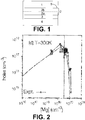
- Fig. 2 is a graph of the hole concentration versus the Mg concentration in a p-GaN at 300K as known from the prior art.
- the experimental points are the hollow circles. They are joined by a broken line. A theoretical line is superimposed on the experimental results. As can be seen, above a certain Mg concentration, the hole concentration starts to drop. This is this effect that is used in embodiments of the present invention to reduce the hole concentration in the second part of the p-GaN gate layer.
- Fig. 3 is a schematic representation of a typical Mg concentration profile obtainable in the prior art (bottom) and in an enhancement-mode GaN transistor obtainable by a method according to an embodiment of the present invention (top).
- the present invention counter-intuitively aims at much higher Mg concentration close to the surface of the p-GaN gate layer than in the prior art.
- the dashed line separates the first and the second part of the p-GaN gate layer. The exact position of this separation is not crucial.
- the top surface of the second part has a Mg concentration above 6x10 19 atoms/cm 3 (hence the second part must encompass the depth 0); that its average concentration is above 3x10 19 atoms/cm 3 ; and that the first part (2a) has an average Mg concentration of at most 3x10 19 atoms/cm 3 and a thickness of at least 3 nm.
- Example 1 method for forming a gate of an enhancement-mode GaN transistor involving the continuous growth of a p-GaN layer via two successive different Cp2Mg flow.
- FIG. 1 An enhancement-mode GaN transistor under construction was provided in a Chemical Vapor Deposition chamber. It comprised a GaN channel layer (4) and an AlGaN barrier layer (3) thereon. A p-GaN layer (2) was then epitaxially grown on the AlGaN barrier layer (3) as follow.
- the chamber was set at a pressure of 200 torr and a temperature of 1010°C. 64 standard liter per minute (slm) N 2 and 120 slm H 2 were flowing in the chamber as ambient gases.
- the Cp2Mg flow was raised to 750 sccm for a second period of 384 seconds while maintaining the NH 3 at its current value but decreasing the TMGa flow to 46 sccm, leading to the formation of a second 40 nm thick Mg-doped GaN layer (2b) epitaxially grown on top of the first p-GaN layer (2a).
- This second p-GaN layer (2b) had a Mg concentration which is so high that it decreases the hole density in the p-GaN layer.
- a TiN layer (1) is then deposited on the second p-GaN layer (2b), thereby forming a Schottky barrier with the second p-GaN layer (2b). Also visible in Fig. 1 is the top surface (5) of the second p-GaN layer (2b) where the highest Mg concentration is present.
- Example 2 method for forming a gate of an enhancement-mode GaN transistor involving the discontinuous growth of a p-GaN layer comprising a first p-GaN growth step, an interruption where only a Cp2Mg flow is present, and a second p-GaN growth step.
- FIG. 1 An enhancement-mode GaN transistor under construction was provided in a chamber. It comprised a GaN channel layer (4) and an AlGaN barrier layer (3) thereon. A p-GaN layer (2) was then epitaxially grown on the AlGaN barrier layer (3) as follow.
- the chamber was set at a pressure of 200 torr and a temperature of 1010°C. 64 standard liter per minute (slm) N 2 and 120 slm H 2 were flowing in the chamber as ambient gases.
- a second p-GaN growth period of 384 seconds was performed by maintaining the Cp2Mg flow at 750 sccm and by resuming a 50 slm NH 3 flow and a 46 TMGa flow, leading to the formation of a second p-GaN layer (2b), 40 nm thick, epitaxially grown on top of the first p-GaN layer (2a).
- This second p-GaN layer (2b) has a Mg concentration which is so high that it decreases the hole density in the p-GaN layer (2).
- a TiN layer (1) was then deposited on the second p-GaN layer, thereby forming a Schottky barrier with the second p-GaN layer.
Landscapes
- Junction Field-Effect Transistors (AREA)
Abstract
a. providing a p-doped AlxGayInzN gate layer (2), consisting of a first (2a) and a second part (2b) on top of one another, above a p-doped Alx'Gay'Inz'N channel layer (4) of an enhancement-mode transistor under construction, and
b. providing a metal gate layer (1) on the top surface of the second part, the metal gate layer being formed of a material such as to form a Schottky barrier with the second part,
wherein providing the p-doped AlxGayInzN gate layer comprises the steps of:
a1. growing the first part above the p-doped Alx'GayInz'N channel layer of the enhancement-mode transistor under construction, the first part having an average Mg concentration of at most 3x10¹⁹ atoms/cm3 and
a2. growing a second part having an average Mg concentration higher than 3x10¹⁹ atoms/cm3 and having a top surface having a Mg concentration higher than 6x10¹⁹ atoms/cm3, on the first part.
Description
- The present invention relates to the field of enhancement mode transistors. More particularly, the invention relates to a method for forming a gate in an enhancement mode transistor.
- Semiconductor devices based on Gallium nitride (GaN) can support high voltages and carry a large current. This makes them promising candidates for power semiconductor devices aimed at high power/high-frequency applications. Devices manufactured for such applications exhibit high electron mobility and are referred to as high electron mobility transistors (HEMT), heterojunction field effect transistors (HFET), or modulation doped field effect transistors (MODFET). These types of devices are typically operated at high frequencies (e.g. 100kHz-10 GHz) and can typically withstand high voltages, e.g., 100 Volts.
- GaN HEMT devices typically include an AlGaN barrier layer adjacent to a GaN layer. The difference in the material in these two layers contributes to a conductive two-dimensional electron gas (2DEG) region near the junction of the two layers and in the layer with the smaller band gap. This 2DEG allows charge to flow through the device. This makes such devices depletion mode devices that are normally "on" when no bias is applied at the gate. Enhancement mode (e-mode, normally "off") devices are however typically more interesting as they are safer and easier to control. An enhancement mode device requires a positive bias applied at the gate in order to conduct current.
- For a GaN HEMT device to work as an enhancement mode device, however, the 2DEG region must be depleted.
- One of the solutions to achieve normally-off (e-mode) operation for GaN HEMT transistors is to employ a p-GaN layer, i.e. a positively doped GaN layer, in the gate region. The fermi-level in the p-GaN will be pulled towards the valence band, lifting up the band-diagram in the GaN channel region achieving the required e-mode operation. The disadvantage of this solution is that the p-GaN gate is a junction type of gate and can thus cause high gate leakage. A solution to lower the gate leakage is to employ a gate metal, which can form a Schottky contact towards the p-GaN. In the cross section, shown in
Figure 1 , the Schottky metal is TiN. However, the leakage of the Schottky metal is in large part determined by the active Mg concentration in the p-GaN layer, where a higher concentration leads to a higher gate leakage. This causes a trade-off between the threshold voltage and gate leakage because to achieve a high threshold voltage, a high active Mg concentration is needed. However, this also leads to increased leakage. -
US2010/0258841 relates to enhancement mode GaN transistors and deals with the problem of high gate leakage when the transistor is turned on by applying a positive voltage to the gate contact.US2010/0258841 remarks that during growth of the p-GaN layer, Mg atoms diffuse to the growth surface. Hence, when growth is terminated, a heavily doped layer exists at the surface and when a positive bias is applied to the gate contact, a large current is generated due to the high doping at the top of this layer.US2010/0258841 proposes to solve this current leakage problem by reducing the Mg concentration to about 1016 atoms per cm3 near the gate contact, thereby allowing the formation of a Schottky contact between the gate contact and the p-type GaN. In addition to reducing the Mg concentration near the gate contact,US2010/0258841 proposes to n-dope the p-GaN gate layer by adding Si atoms near the gate contact in order to further reduce the hole density. However,US2010/0258841 does not propose an experimental way enabling the reduction of the Mg concentration near the gate contact. In fact, it is very difficult to achieve such a reduction because, due to the dynamics of the MOCVD growth, a surface peak Mg concentration will typically be present near the top. Furthermore, Si counter-doping is not easier since it requires matching exactly the Mg concentration and requires, therefore, full counter doping. Indeed, if the counter-doping is incomplete, gate leakage is to be expected and if the counter-doping is excessive, it will create highly doped n-layer near the top of the device. - There is, therefore, a need in the art for new ways to deal with the problem of high gate leakage.
- It is an object of the present invention to provide good methods for forming a gate of an enhancement-mode transistor presenting limited gate leakage. It is a further object of the present invention to provide enhancement-mode transistors comprising such a gate.
- It is an advantage of embodiments of the present invention that a depletion region can be formed at the interface with the metal gate layer, thereby enabling the formation of a Schottky barrier.
- It is an advantage of embodiments of the present invention that this depletion region can be relatively uniform.
- It is an advantage of embodiments of the present invention that the extent of this depletion region and its hole concentration can be easily controlled.
- It is an advantage of embodiments of the present invention that the hole concentration in this depletion region can be relatively easily set at any value.
- The above objective is accomplished by a method and device according to the present invention.
- In a first aspect, the present invention relates to a method for forming a gate of an enhancement-mode transistor, the method comprising the steps of:
- a. providing a p-doped AlxGayInzN gate layer, consisting of a first and a second part on top of one another, above a Alx'Gay'Inz'N channel layer of an enhancement-mode transistor under construction wherein x+y+z is 1 and wherein x'+y'+z' is 1, and
- b. providing a metal gate layer on the top surface of the second part of the p-doped AlxGayInzN gate layer, the metal gate layer being formed of a material such as to form a Schottky barrier with the second part of the p-doped AlxGayInzN gate layer,
- a1. growing the first part of the p-doped AlxGayInzN gate layer until the first part reaches a thickness of at least 3 nm, above the Alx'Gay'Inz'N channel layer of the enhancement-mode transistor under construction, the first part having an average Mg concentration of at most 3x10¹⁹ atoms/cm3, and
- a2. growing a second part of the p-doped AlxGayInzN gate layer, the second part having an average Mg concentration higher than 3x10¹⁹ atoms/cm3 and having a top surface having a Mg concentration higher than 6x10¹⁹ atoms/cm3, on the first part of the p-doped AlxGayInzN gate layer.
- In a second aspect, the present invention relates to an enhancement-mode transistor comprising a gate obtainable by the method of the first aspect. In particular, it relates to an enhancement-mode transistor comprising:
- a. a p-doped AlxGayInzN gate layer, consisting of a first and a second part on top of one another, above an Alx'Gay'Inz'N channel layer, wherein x+y+z is 1 and x'+y'+z' is 1, and
- b. a metal gate layer on the top surface of the second part of the p-doped AlxGayInzN gate layer, the metal gate layer being formed of a material such as to form a Schottky barrier with the second part of the p-doped AlxGayInzN gate layer,
- Particular and preferred aspects of the invention are set out in the accompanying independent and dependent claims. Features from the dependent claims may be combined with features of the independent claims and with features of other dependent claims as appropriate and not merely as explicitly set out in the claims.
- Although there has been constant improvement, change and evolution of devices in this field, the present concepts are believed to represent substantial new and novel improvements, including departures from prior practices, resulting in the provision of more efficient, stable and reliable devices of this nature.
- The above and other characteristics, features and advantages of the present invention will become apparent from the following detailed description, taken in conjunction with the accompanying drawings, which illustrate, by way of example, the principles of the invention. This description is given for the sake of example only, without limiting the scope of the invention. The reference figures quoted below refer to the attached drawings.
-
-
Fig. 1 is a schematic representation of a cross-section of a stack of layers comprised in an enhancement-mode GaN transistor obtained by a method according to an embodiment of the present invention. -
Fig. 2 is a graph of the hole concentration versus the Mg concentration in a p-GaN as known from the prior art. -
Fig. 3 is a schematic representation of a typical Mg concentration profile obtainable in the prior art (bottom) and in an enhancement-mode GaN transistor obtainable by a method according to an embodiment of the present invention (top). - The present invention will be described with respect to particular embodiments and with reference to certain drawings but the invention is not limited thereto but only by the claims. The drawings described are only schematic and are non-limiting. In the drawings, the size of some of the elements may be exaggerated and not drawn on scale for illustrative purposes. The dimensions and the relative dimensions do not correspond to actual reductions to practice of the invention.
- Furthermore, the terms first, second, third and the like in the description and in the claims, are used for distinguishing between similar elements and not necessarily for describing a sequence, either temporally, spatially, in ranking or in any other manner. It is to be understood that the terms so used are interchangeable under appropriate circumstances and that the embodiments of the invention described herein are capable of operation in other sequences than described or illustrated herein.
- Moreover, the terms top, bottom, over, under and the like in the description and the claims are used for descriptive purposes and not necessarily for describing relative positions. It is to be understood that the terms so used are interchangeable under appropriate circumstances and that the embodiments of the invention described herein are capable of operation in other orientations than described or illustrated herein.
- It is to be noticed that the term "comprising", used in the claims, should not be interpreted as being restricted to the means listed thereafter; it does not exclude other elements or steps. It is thus to be interpreted as specifying the presence of the stated features, integers, steps or components as referred to but does not preclude the presence or addition of one or more other features, integers, steps or components, or groups thereof. Thus, the scope of the expression "a device comprising means A and B" should not be limited to devices consisting only of components A and B. It means that with respect to the present invention, the only relevant components of the device are A and B.
- Reference throughout this specification to "one embodiment" or "an embodiment" means that a particular feature, structure or characteristic described in connection with the embodiment is included in at least one embodiment of the present invention. Thus, appearances of the phrases "in one embodiment" or "in an embodiment" in various places throughout this specification are not necessarily all referring to the same embodiment, but may. Furthermore, the particular features, structures or characteristics may be combined in any suitable manner, as would be apparent to one of ordinary skill in the art from this disclosure, in one or more embodiments.
- Similarly, it should be appreciated that in the description of exemplary embodiments of the invention, various features of the invention are sometimes grouped together in a single embodiment, figure, or description thereof for the purpose of streamlining the disclosure and aiding in the understanding of one or more of the various inventive aspects. This method of disclosure, however, is not to be interpreted as reflecting an intention that the claimed invention requires more features than are expressly recited in each claim. Rather, as the following claims reflect, inventive aspects lie in less than all features of a single foregoing disclosed embodiment. Thus, the claims following the detailed description are hereby expressly incorporated into this detailed description, with each claim standing on its own as a separate embodiment of this invention.
- Furthermore, while some embodiments described herein include some but not other features included in other embodiments, combinations of features of different embodiments are meant to be within the scope of the invention, and form different embodiments, as would be understood by those in the art. For example, in the following claims, any of the claimed embodiments can be used in any combination.
- In the description provided herein, numerous specific details are set forth. However, it is understood that embodiments of the invention may be practiced without these specific details. In other instances, well-known methods, structures, and techniques have not been shown in detail in order not to obscure an understanding of this description.
- The following terms are provided solely to aid in the understanding of the invention.
- Mg concentrations in atoms/cm3 can be measured by Secondary Ion Mass Spectrometry (SIMS).
- The invention will now be described by a detailed description of several embodiments of the invention. It is clear that other embodiments of the invention can be configured according to the knowledge of persons skilled in the art without departing from the technical teaching of the invention, the invention being limited only by the terms of the appended claims.
- Reference will be made to transistors. These are devices having a first main electrode such as a drain, a second main electrode such as a source and a control electrode such as a gate for controlling the flow of electrical charges between the first and second main electrodes.
- Without being bound by theory, it is believed that the invention works via a self-compensation effect occurring when the Mg concentration passes a certain threshold concentration. This threshold concentration is at about 3x10¹⁹ atoms/cm3. Below that threshold, an increase in Mg concentration in the p-GaN layer translates into an increase in hole concentration in that layer. Above that threshold, the hole concentration first stagnates and then drops rapidly once a value of at least 6x10¹⁹ atoms/cm3 is reached. In mechanistic terms, this effect can be explained by the fact that above the threshold, additional Mg atoms create point defects (Mg interstitials, nitrogen vacancies) which compensate the Mg already present, thereby reducing the hole concentration instead of increasing it. The present invention uses this property for going around the difficulties of achieving a controllable low Mg concentration in the p-GaN layer near the metal gate layer by counter-intuitively increasing the Mg concentration instead of decreasing it. The end result is a low hole concentration in the p-GaN layer close to the metal gate layer.
- The first aspect of the present invention relates to a method for forming a gate of an enhancement-mode transistor. The gate comprises and typically consists of a p-doped AlxGayInzN gate layer with a metal gate layer thereon.
- The p-doped AlxGayInzN gate layer is an AlxGayInzN layer doped with Mg.
- The p-doped AlxGayInzN gate layer consists of a first and a second part on top of one another. The second part is grown epitaxially on top of the first part during either a continuous or a discontinuous growth process. The first part has an average Mg concentration of at most 3x10¹⁹ atoms/cm3 and the second part has an average Mg concentration higher than 3x10¹⁹ atoms/cm3 and has a top surface having a Mg concentration above 6x10¹⁹ atom/cm3.
- The average Mg concentration in the first part is preferably higher than 0.5x10¹⁹, preferably higher than 1x10¹⁹ atoms/cm3, yet more preferably higher than 2x10¹⁹ to allow a sufficiently high hole concentration to achieve a "normally off" mode. A Mg concentration in the first part at 3x10¹⁹ is most preferable.
- In embodiments, the second part of the p-doped AlxGayInzN gate layer may have an average Mg concentration higher than 4x10¹⁹ atoms/cm3, preferably higher than 5x10¹⁹ atoms/cm3. This contributes to reducing the hole concentration in the second part, which helps reducing current leakage.
- The Mg concentration is typically not homogeneous across the thickness of each part as it tends to be higher at the growth front of the part than at higher depth in the part. This concentration, therefore, tends to be higher near the top and lower near the bottom of the part.
- The Mg concentration at the top of the first part is preferably lower than 4x10¹⁹ atoms/cm3, more preferably lower than 3.5x10¹⁹ atoms/cm3 and most preferably at most 3x10¹⁹ atoms/cm3.
- The Mg concentration at the bottom of the second part is equal or higher than the Mg concentration at the top of the first part. It will be about equal or slightly higher if a continuous p-doped AlxGayInzN growth process is used and it will be higher if a discontinuous p-doped AlxGayInzN growth process is used and an interruption in the p-doped AlxGayInzN growth process is used to only flow a Mg precursor without Ga, In, and Al precursor and/or without N precursor in the growth environment before to resume p-doped AlxGayInzN growth.
- The Mg concentration at the top of the second part is higher than 6x10¹⁹ atoms/cm3.
- In embodiments, the top surface of the second part of the p-doped AlxGayInzN gate layer may have a Mg concentration higher than 7x10¹⁹ atoms/cm3, preferably higher than 7.5x10¹⁹ atoms/cm3. This contributes to drastically reducing the hole concentration in the second part, which helps reducing current leakage.
- In embodiments, the first part of the p-doped AlxGayInzN gate layer may have a bottom surface, closest to the channel layer, having a Mg concentration lower than 2x10¹⁹ atoms/cm3.
- In embodiments, the thickness of the first part may be from 10 to 60 nm. In embodiments, the thickness of the second part may be at least 20 nm and preferably at least 30 nm. Preferably, the top 10 nm of the second part have an average Mg concentration above 6x10¹⁹ atoms/cm3.
- Step a of forming the p-doped AlxGayInzN gate layer is typically performed by chemical vapor deposition (CVD) and more precisely by metal organic chemical vapor deposition (MOCVD), i.e. a CVD method involving the use of one or more metalorganic precursors. Typically, all steps involving flowing a precursor gas are performed in presence of a carrier gas, preferably a reductive gas mixture such as an N2/H2 gas mixture.
- In the p-doped AlxGayInzN gate layer, the sum of x, y and z amount to 1. Preferably, y amounts to at least 0.5. More preferably y amounts to at least 0.8. Yet more preferably, y amounts to at least 0.9. Most preferably, y equals 1.
- The Alx'Gay'Inz'N channel layer above which the p-doped AlxGayInzN gate layer is formed is also typically formed by chemical vapor deposition, on a substrate. Also, an Alx"Gay"Inz"N barrier layer, wherein x" + y" + y" is 1, typically present between the Alx'Gay'Inz'N channel layer and the p-doped AlxGayInzN gate layer is also typically formed by chemical vapor deposition. Hence, typically, the Alx'Gay'Inz'N channel layer is epitaxially grown on a substrate, the Alx"Gay"Inz"N barrier layer is epitaxially grown on the Alx'Gay'Inz'N channel layer, the first part of the p-doped AlxGayInzN gate layer is epitaxially grown (typically on the Alx"Gay"Inz"N barrier layer), and the second part of the p-doped AlxGayInzN gate layer is epitaxially grown on the first part of the p-doped AlxGayInzN layer.
- In the Alx'Gay'Inz'N channel layer, the sum of x', y' and z' amount to 1. Preferably, y' amounts to at least 0.5. More preferably y' amounts to at least 0.8. Yet more preferably, y' amounts to at least 0.9. Most preferably, y' equals 1. Preferably, but not necessarily, x=x', y=y' and z=z'.
- The average Mg concentration in the channel layer is preferably less than 0.5x10¹⁹ and more preferably less than 1x10¹⁸ atoms/cm3. In embodiments, the Alx'Gay'Inz'N channel layer is not doped.
- Typically, step a and b are both performed in a deposition chamber (e.g. a CVD deposition chamber) and more preferably in the same deposition chamber. Steps a1 and a2 are typically performed in the same deposition chamber.
- In an embodiment of the method of the first aspect of the present invention, wherein step a is performed in a deposition chamber, step a2 may comprise
- (i) stopping the growth of the first part, then
- (ii) providing the chamber with a flow of a Mg precursor gas and no flow of Ga, In, and Al precursor gases (i.e. without Ga precursor gases, without In precursor gases and without Al precursor gases) and/or no flow of N precursor gas, then
- (iii) without flushing the chamber from the Mg precursor contained therein, providing the chamber with a flow of a Mg precursor gas, a flow of one or more precursor gases selected from Ga, In and Al precursor gases and a flow of an N precursor gas so as to grow the second part.
- Preferably, the flow of Ga equals at least 50%, preferably at least 80%, more preferably 90% and most preferably 100% of the flow of one or more precursor gases selected from Ga, In and Al precursor gases.
- This embodiment, where a discontinuous growth process is performed comprising an interruption in the provision of N and/or Ga, In and Al precursors, is advantageous because Mg concentration in the growing p-doped AlxGayInzN layer increases in general only very slowly in reaction to an increase in Mg flow. The interruption of the N and/or Ga, In and Al flows allows the amount of Mg in the chamber and on the top surface of the first part to build up before resuming growth of the p-doped AlxGayInzN gate layer, thereby permitting a more abrupt change from a relatively low Mg concentration in the first part of the p-doped AlxGayInzN gate layer to a relatively high Mg concentration in the second part of the p-doped AlxGayInzN gate layer.
- Step (i) of stopping the growth of the first part typically consists in stopping the flow of Ga, In and Al and/or N precursor. For this purpose, at least one of the flow of Ga, In and Al precursor and the flow of N precursor is stopped, preferably all of them. In embodiments, steps (i) and (ii) can be combined by stopping the flow of Ga, In and Al precursors and/or N precursors while keeping a flow of Mg precursor, (e.g. the same flow or a higher flow). At the end of step (ii), the chamber contains Mg precursors in its atmosphere and typically on its walls. Step (iii) is performed without flushing the chamber from these Mg precursors. Providing in step (iii) the flow of Mg precursor gas can in some embodiments be performed by keeping or increasing the flow of Mg precursor provided in step (ii). In embodiments, the transition between steps (ii) and (iii) can, therefore, be achieved by providing a flow of one or more of Ga, In and Al precursors and N precursors while keeping or raising the flow of Mg precursor.
- In embodiments, step (ii) may be performed in such a way as to saturate the atmosphere of the chamber with the Mg precursor. This is advantageous because it contributes to incorporating as much Mg precursor as possible in the second part of the p-doped AlxGayInzN gate layer, which leads to a hole concentration in the second part which is as low as possible.
- The flow of each precursor during each step is adapted to achieve the desired Mg concentrations.
- Achieving any particular Mg concentration can be done by adapting the flow ratio between on one hand the flow of the Mg precursors and on another hand the flow of Al, Ga and In precursors so as to achieve the desired concentration.
- For instance, achieving any particular Mg concentration can be done by adapting the flow of the Mg precursor so as to achieve the desired concentration.
- The obtained Mg concentration profile for a particular selection of flows is apparatus, temperature and pressure dependent and can be straightforwardly determined by trial and error.
- In embodiments, the flow of the Mg precursor gas in step (ii) of step a2 may be higher than a flow of Mg precursor gas used to grow the first part in step a1. This is advantageous because it contributes to incorporating as much Mg precursor as possible in the second part of the p-doped AlxGayInzN gate layer, which leads to a hole concentration which suitably low.
- In embodiments, step (ii) may be performed for from 5 to 15 seconds, preferably from 8 to 12 seconds. This is typically long enough to assure that the chamber is sufficiently rich in Mg to obtain a second part of the p-doped AlxGayInzN gate layer gate layer having an average Mg concentration higher than 3x10¹⁹ atoms/cm3 and having a top surface having a Mg concentration higher than 6x10¹⁹ atoms/cm3 while simultaneously not being so long as to unnecessarily lengthen the process. Longer periods are of course also working but are less advantageous.
- In embodiments, step a1 may be performed at any temperature permitting the growth of the first part of the p-doped AlxGayInzN gate layer. For instance, a temperature of from 900 to 1050°C may be used.
- In embodiments, step (ii) of step a2 and optionally step (iii) of step a2 may be performed at a temperature of from 900 to 1000°C, preferably from 930 to 970°C. Using a lower temperature for step a2 than for step a1 permits to reduce the tendency of Mg to migrate in the first part during the formation of the second part.
- In embodiments, step a1 may be performed until the first part of the p-doped AlxGayInzN gate layer reaches a thickness of from 3 to 60, preferably 5 to 60 and more preferably 10 to 60 nm. Having the first part in this thickness range is advantageous as it is sufficiently thick not to negatively impact the threshold voltage.
- In embodiments, step a2 may be performed until the second part of the p-doped AlxGayInzN gate layer reaches at least a thickness of 20 nm, preferably at least 30nm. Such a thickness of low hole concentration p-doped AlxGayInzN close to the gate metal contributes to a good Schottky contact and a low leakage current.
- In step b, the material of the metal gate layer is such that a Schottky barrier with the second part of the p-doped AlxGayInzN gate layer is formed. This is typically performed by selecting the material composing the metal gate layer in such a way that at equilibrium its fermi level lies in the band gap of the second part of the p-doped AlxGayInzN gate layer but above its valence band edge.
- The Mg precursor can be any precursor, or a combination thereof, known to the skilled person for doping an AlxGayInzN layer during CVD. For instance, it can be bis-cyclopentadienyl magnesium (CpMg).
- The N precursor can be any N precursor, or a combination thereof, known to the skilled person for forming an AlxGayInzN layer. For instance, it can be NH3, phenyl hydrazine, dimethylhydrazine, or tert-butylamine.
- The Ga precursor can be any Ga precursor, or a combination thereof, known to the skilled person for forming an AlxGayInzN layer. For instance, it can be trimethylgallium or triethylgallium.
- In embodiments, the method may further comprise providing an Alx"Gay"Inz"N barrier layer on the Alx'Gay'Inz'N channel layer, wherein the p-doped AlxGayInzN gate layer is provided above and for instance on the Alx"Gay"Inz"N barrier layer, wherein x"+y"+z" is 1. The barrier layer is typically a layer having a larger band gap than the channel layer. In embodiments where the p-doped AlxGayInzN gate layer is provided above (but not on) the Alx"Gay"Inz"N barrier layer, more than one layer is present between the Alx'Gay'Inz'N channel layer and the p-doped AlxGayInzN gate layer. This plurality of layers situated between the channel layer and the gate layer may be collectively referred to as a barrier. This barrier comprises the barrier layer mentioned herein as its bottom layer. To achieve a larger bandgap, in embodiments, x" may be larger than x'. Preferably, x<x">x'. Indeed, increasing x" tend to increase the bandgap of the Alx"Gay"Inz"N barrier layer. Of less impact, the ratio y"/z" may be larger than the ratio y'/z'. Preferably, (y/z)<(y"/z")>(y'/z'). Indeed, the larger this ratio y"/z", the larger the bandgap for a same x".
- Preferably, the polarization (spontaneous & piezoelectrical) of the barrier layer may be larger than the polarization of the channel. This is advantageous as it promotes the formation of a 2DEG in the channel. To achieve a larger polarization, in embodiments, x" may be larger than x'. Preferably, x<x">x'. Indeed, increasing x" tend to increase the polarization of the Alx"Gay"Inz"N barrier layer. Of less impact, the ratio z"/y" may be larger than the ratio z'/y'. Preferably, (z/y)<(z"/y")>(z'/y'). Indeed, the larger this ratio z"/y", the larger the bandgap for a same x".
- Since the bandgap is most efficiently increased by increasing x" over y" and by increasing y" over z" and since the polarization is most efficiently increased by increasing x" over z" and by increasing z" over y", x<x">x' is advantageous for both increasing bandgap and for increasing polarization. On another hand, whether the ratio y"/z" is better increased or decreased in the barrier compared to the channel material will depend on the relative need for an increased band gap and an increased polarization in the device under construction.
- In some particularly preferred embodiments, x and x' = 0 and x" is larger than 0. In even more preferred embodiments, x = x' = z = z' = z" = 0 and x" is larger than 0 and is preferably from 0.15 to 0.30 and more preferably from 0.20 to 0.25.
- In embodiments, the lattice constants of the p-doped gate layer may be matching the lattice constant of the channel layer. Preferably, the lattice constants of the p-doped gate layer may be matching the lattice constant of the barrier layer. Preferably, the lattice constants of the p-doped gate layer may be matching the lattice constant of the channel layer and the barrier layer. In other embodiments, the lattice constant of the channel layer may be different from the lattice constant of the barrier layer in order to induce strain in the channel layer.
- Suitable Al precursors for the formation of the barrier layer are for instance trimethylaluminum (TMAI), triethylaluminum (TEAl). The nitrogen precursor and the gallium precursor can be for instance as mentioned earlier. In a second aspect, the present invention relates to an enhancement-mode transistor comprising a gate obtainable by the method of the first aspect. In particular, it relates to an enhancement-mode transistor comprising:
- a. a p-doped AlxGayInzN gate layer, consisting of a first and a second part on top of one another, above an Alx'Gay'Inz'N channel layer, wherein x+y+z is 1 and x'+y'+z' is 1, and
- b. a metal gate layer on the top surface of the second part of the p-doped AlxGayInzN gate layer, the metal gate layer being formed of a material such as to form a Schottky barrier with the second part of the p-doped AlxGayInzN gate layer,
- Any feature of the second aspect can be as described for corresponding features of the first aspect.
-
Fig. 2 is a graph of the hole concentration versus the Mg concentration in a p-GaN at 300K as known from the prior art. The experimental points are the hollow circles. They are joined by a broken line. A theoretical line is superimposed on the experimental results. As can be seen, above a certain Mg concentration, the hole concentration starts to drop. This is this effect that is used in embodiments of the present invention to reduce the hole concentration in the second part of the p-GaN gate layer. -
Fig. 3 is a schematic representation of a typical Mg concentration profile obtainable in the prior art (bottom) and in an enhancement-mode GaN transistor obtainable by a method according to an embodiment of the present invention (top). As can be seen, the present invention counter-intuitively aims at much higher Mg concentration close to the surface of the p-GaN gate layer than in the prior art. The dashed line separates the first and the second part of the p-GaN gate layer. The exact position of this separation is not crucial. What matter is that the top surface of the second part has a Mg concentration above 6x10¹⁹ atoms/cm3 (hence the second part must encompass the depth 0); that its average concentration is above 3x10¹⁹ atoms/cm3; and that the first part (2a) has an average Mg concentration of at most 3x10¹⁹ atoms/cm3 and a thickness of at least 3 nm. - We now refer to
Fig. 1 . An enhancement-mode GaN transistor under construction was provided in a Chemical Vapor Deposition chamber. It comprised a GaN channel layer (4) and an AlGaN barrier layer (3) thereon. A p-GaN layer (2) was then epitaxially grown on the AlGaN barrier layer (3) as follow. The chamber was set at a pressure of 200 torr and a temperature of 1010°C. 64 standard liter per minute (slm) N2 and 120 slm H2 were flowing in the chamber as ambient gases. Then, for a period of 192 seconds, 50 slm NH3, 92 standard cubic centimetres per minute (sccm) trimethylgallium (TMGa), and 500 sccm bis(cyclopentadienyl)magnesium (Cp2Mg) were flown through the chamber, in addition to the N2 and H2 gases, leading to the formation of a first 40 nm thick Mg-doped GaN layer (2a). This first p-GaN layer (2a) had a relatively low Mg concentration. Then, without interruption, the Cp2Mg flow was raised to 750 sccm for a second period of 384 seconds while maintaining the NH3 at its current value but decreasing the TMGa flow to 46 sccm, leading to the formation of a second 40 nm thick Mg-doped GaN layer (2b) epitaxially grown on top of the first p-GaN layer (2a). This second p-GaN layer (2b) had a Mg concentration which is so high that it decreases the hole density in the p-GaN layer. A TiN layer (1) is then deposited on the second p-GaN layer (2b), thereby forming a Schottky barrier with the second p-GaN layer (2b). Also visible inFig. 1 is the top surface (5) of the second p-GaN layer (2b) where the highest Mg concentration is present. - This example gives an alternative way to form a gate according to embodiments of the present invention. We still refer to
Fig. 1 . An enhancement-mode GaN transistor under construction was provided in a chamber. It comprised a GaN channel layer (4) and an AlGaN barrier layer (3) thereon. A p-GaN layer (2) was then epitaxially grown on the AlGaN barrier layer (3) as follow. The chamber was set at a pressure of 200 torr and a temperature of 1010°C. 64 standard liter per minute (slm) N2 and 120 slm H2 were flowing in the chamber as ambient gases. Then, for a period of 192 seconds, 50 slm NH3, 92 sccm TMGa, and 500 sccm Cp2Mg were flown through the chamber in addition to the N2 and H2 gases, leading to the formation of a first 40 nm thick Mg-doped GaN layer (2a). This first p-GaN layer (2a) had a relatively low Mg concentration. Then, the flows of NH3 and TMGa were interrupted for a period of 10 seconds during which the Cp2Mg flow was raised to 750 sccm. Next, a second p-GaN growth period of 384 seconds was performed by maintaining the Cp2Mg flow at 750 sccm and by resuming a 50 slm NH3 flow and a 46 TMGa flow, leading to the formation of a second p-GaN layer (2b), 40 nm thick, epitaxially grown on top of the first p-GaN layer (2a). This second p-GaN layer (2b) has a Mg concentration which is so high that it decreases the hole density in the p-GaN layer (2). A TiN layer (1) was then deposited on the second p-GaN layer, thereby forming a Schottky barrier with the second p-GaN layer. - It is to be understood that although preferred embodiments, specific constructions and configurations, as well as materials, have been discussed herein for devices according to the present invention, various changes or modifications in form and detail may be made without departing from the scope of this invention. For example, any formulas given above are merely representative of procedures that may be used. Steps may be added or deleted to methods described within the scope of the present invention.
Claims (15)
- A method for forming a gate (1, 2) of an enhancement-mode transistor, the method comprising the steps of:a. providing a p-doped AlxGayInzN gate layer (2), consisting of a first (2a) and a second part (2b) on top of one another, above a AlxGay'Inz'N channel layer (4) of an enhancement-mode transistor under construction wherein x+y+z is 1 and wherein x'+y'+z' is 1, andb. providing a metal gate layer (1) on the top surface of the second part (2b) of the p-doped AlxGayInzN gate layer (2), the metal gate layer (1) being formed of a material such as to form a Schottky barrier with the second part (2b) of the p-doped AlxGayInzN gate layer (2),wherein providing the p-doped AlxGayInzN gate layer (2) comprises the steps of:a1. growing the first part (2a) of the p-doped AlxGayInzN gate layer (2) until the first part (2a) reaches a thickness of at least 3 nm, above the Alx'Gay'Inz'N channel layer (4) of the enhancement-mode transistor under construction, the first part (2a) having an average Mg concentration of at most 3x10¹⁹ atoms/cm3, anda2. growing a second part (2b) of the p-doped AlxGayInzN gate layer (2), the second part (2b) having an average Mg concentration higher than 3x10¹⁹ atoms/cm3 and having a top surface (5) having a Mg concentration higher than 6x10¹⁹ atoms/cm3, on the first part (2a) of the p-doped AlxGayInzN gate layer (2).
- The method according to claim 1, wherein step a is performed by chemical vapor deposition.
- The method according to claim 1 or claim 2, wherein step a is performed in a deposition chamber and wherein step a2 comprises(i) stopping the growth of the first part (2a), then(ii) providing the chamber with a flow of a Mg precursor gas and no flow of Ga, In, and Al precursor gases and/or no flow of N precursor gas, then(iii) without flushing the chamber from the Mg precursor contained therein, providing the chamber with a flow of a Mg precursor gas, a flow of one or more precursor gases selected from Ga, In, and Al precursor gases and a flow of an N precursor gas so as to grow the second part (2b).
- The method according to claim 3, wherein step (ii) is performed in such a way as to saturate the atmosphere of the chamber with the Mg precursor.
- The method according to claim 3 or claim 4, wherein the flow of the Mg precursor gas in step (ii) of step a2 is higher than a flow of Mg precursor gas used to grow the first part (2a) in step a1.
- The method according to any one of claims 3 to 5 wherein step (ii) is performed for from 5 to 15 seconds, preferably from 8 to 12 seconds.
- The method according to any one of claims 3 to 6 wherein step (ii) and optionally step (iii) are performed at a temperature of from 900 to 1000°C, preferably from 930 to 970°C.
- The method according to any one of the preceding claims, wherein step a1 is performed until the first part (2a) of the p-doped AlxGayInzN gate layer (2) reaches a thickness of from 10 to 60 nm.
- The method according to any one of the preceding claims, wherein the Mg concentration at the bottom of the first part (2a), away from the second part (2b), is lower than the concentration at the top of the first part (2a), at the interface with the second part (2b).
- The method according to any one of the preceding claims, further comprising providing an Alx"Gay"Inz"N barrier layer (3), on the Alx'Gay'Inz'N channel layer (4), wherein the p-doped AlxGayInzN gate layer (2) is provided on the Alx"Gay"Inz"N barrier layer (3), wherein x"+y"+z" is 1 and wherein x<x">x'.
- The method according to any one of the preceding claims, wherein the second part (2b) of the p-doped AlxGayInzN gate layer (2) has an average Mg concentration higher than 4x10¹⁹ atoms/cm3, preferably higher than 5x10¹⁹ atoms/cm3.
- The method according to any one of the preceding claims, wherein the top surface (5) of the second part of the p-doped AlxGayInzN gate layer has a Mg concentration higher than 7x10¹⁹ atoms/cm3, preferably higher than 7.5x10¹⁹ atoms/cm3.
- The method according to any one of the preceding claims, wherein the first part (2a) of the p-doped AlxGayInzN gate layer (2) has a bottom surface, closest to the channel layer (3), having a Mg concentration lower than 2x10¹⁹ atoms/cm3.
- The method according to any one of the preceding claims, wherein step a2 is performed until the second part (2b) of the p-doped AlxGayInzN gate layer reaches at least a thickness of 20 nm, preferably at least 30nm.
- An enhancement-mode transistor comprising:a. a p-doped AlxGayInzN gate layer (2), consisting of a first (2a) and a second part (2b) on top of one another, above an Alx'Gay'Inz'N channel layer (4), wherein x+y+z is 1 and x'+y'+z' is 1, andb. a metal gate layer (1) on the top surface (5) of the second part (2b) of the p-doped AlxGayInzN gate layer (2), the metal gate layer (1) being formed of a material such as to form a Schottky barrier with the second part (2b) of the p-doped AlxGayInzN gate layer (2),wherein the first part (2a) of the p-doped AlxGayInzN gate layer (2) has an average Mg concentration of at most 3x10¹⁹ atoms/cm3 and wherein the second part (2b) of the p-doped AlxGayInzN gate layer (2), on the first part (2a) and in physical contact with the metal gate layer (1), has an average Mg concentration higher than 3x10¹⁹ atoms/cm3 and a top surface (5) having a Mg concentration higher than 6x10¹⁹ atoms/cm3.
Priority Applications (3)
| Application Number | Priority Date | Filing Date | Title |
|---|---|---|---|
| EP17186014.1A EP3442026B1 (en) | 2017-08-11 | 2017-08-11 | Gate for an enhancement-mode transistor |
| US16/050,776 US10686052B2 (en) | 2017-08-11 | 2018-07-31 | Gate for an enhancement-mode transistor |
| JP2018151555A JP7184564B2 (en) | 2017-08-11 | 2018-08-10 | Gate for enhancement mode transistor |
Applications Claiming Priority (1)
| Application Number | Priority Date | Filing Date | Title |
|---|---|---|---|
| EP17186014.1A EP3442026B1 (en) | 2017-08-11 | 2017-08-11 | Gate for an enhancement-mode transistor |
Publications (2)
| Publication Number | Publication Date |
|---|---|
| EP3442026A1 true EP3442026A1 (en) | 2019-02-13 |
| EP3442026B1 EP3442026B1 (en) | 2023-03-08 |
Family
ID=59626485
Family Applications (1)
| Application Number | Title | Priority Date | Filing Date |
|---|---|---|---|
| EP17186014.1A Active EP3442026B1 (en) | 2017-08-11 | 2017-08-11 | Gate for an enhancement-mode transistor |
Country Status (3)
| Country | Link |
|---|---|
| US (1) | US10686052B2 (en) |
| EP (1) | EP3442026B1 (en) |
| JP (1) | JP7184564B2 (en) |
Families Citing this family (6)
| Publication number | Priority date | Publication date | Assignee | Title |
|---|---|---|---|---|
| US11121230B2 (en) | 2018-09-21 | 2021-09-14 | Taiwan Semiconductor Manufacturing Co., Ltd. | Structures and methods for controlling dopant diffusion and activation |
| JP7162580B2 (en) * | 2018-12-12 | 2022-10-28 | クアーズテック株式会社 | Nitride semiconductor substrate and nitride semiconductor device |
| US20210399121A1 (en) * | 2020-06-18 | 2021-12-23 | The Regents Of The University Of California | Novel approach to controlling linearity in n-polar gan mishemts |
| US11942326B2 (en) * | 2020-12-16 | 2024-03-26 | Semiconductor Components Industries, Llc | Process of forming an electronic device including a doped gate electrode |
| WO2022183503A1 (en) | 2021-03-05 | 2022-09-09 | Huawei Technologies Co., Ltd. | Gallium nitride power transistor |
| KR102578828B1 (en) | 2021-03-29 | 2023-09-15 | 삼성전자주식회사 | High electron mobility transistor |
Citations (2)
| Publication number | Priority date | Publication date | Assignee | Title |
|---|---|---|---|---|
| US20100258841A1 (en) | 2009-04-08 | 2010-10-14 | Alexander Lidow | Back diffusion suppression structures |
| US20170133500A1 (en) * | 2014-07-29 | 2017-05-11 | Panasonic Intellectual Property Management Co., Ltd. | Nitride semiconductor device |
Family Cites Families (15)
| Publication number | Priority date | Publication date | Assignee | Title |
|---|---|---|---|---|
| JP2827794B2 (en) * | 1993-02-05 | 1998-11-25 | 日亜化学工業株式会社 | Method for growing p-type gallium nitride |
| JP2666237B2 (en) * | 1994-09-20 | 1997-10-22 | 豊田合成株式会社 | Group III nitride semiconductor light emitting device |
| TW200711171A (en) | 2005-04-05 | 2007-03-16 | Toshiba Kk | Gallium nitride based semiconductor device and method of manufacturing same |
| JP4712459B2 (en) * | 2005-07-08 | 2011-06-29 | パナソニック株式会社 | Transistor and method of operating the same |
| JP4806993B2 (en) | 2005-08-03 | 2011-11-02 | 住友電気工業株式会社 | Method for forming group III-V compound semiconductor film |
| JP2007220895A (en) * | 2006-02-16 | 2007-08-30 | Matsushita Electric Ind Co Ltd | Nitride semiconductor device and manufacturing method thereof |
| JP4755961B2 (en) * | 2006-09-29 | 2011-08-24 | パナソニック株式会社 | Nitride semiconductor device and manufacturing method thereof |
| JP2010225765A (en) * | 2009-03-23 | 2010-10-07 | Panasonic Corp | Semiconductor device and manufacturing method thereof |
| WO2010118101A1 (en) | 2009-04-08 | 2010-10-14 | Efficient Power Conversion Corporation | Dopant diffusion modulation in gan buffer layers |
| JP2011029247A (en) * | 2009-07-22 | 2011-02-10 | Panasonic Corp | Nitride semiconductor device and method of manufacturing the same |
| JP6174874B2 (en) * | 2013-03-15 | 2017-08-02 | ルネサスエレクトロニクス株式会社 | Semiconductor device |
| US8866192B1 (en) * | 2013-07-17 | 2014-10-21 | Taiwan Semiconductor Manufacturing Company, Ltd. | Semiconductor device, high electron mobility transistor (HEMT) and method of manufacturing |
| US20150340562A1 (en) * | 2014-05-20 | 2015-11-26 | Seoul Viosys Co., Ltd. | Light emitting device and method of fabricating the same |
| JP6817559B2 (en) * | 2015-10-27 | 2021-01-20 | パナソニックIpマネジメント株式会社 | Semiconductor device |
| US20180331255A1 (en) * | 2017-05-12 | 2018-11-15 | X Development Llc | Fabrication of ultraviolet light emitting diode with tunnel junction |
-
2017
- 2017-08-11 EP EP17186014.1A patent/EP3442026B1/en active Active
-
2018
- 2018-07-31 US US16/050,776 patent/US10686052B2/en active Active
- 2018-08-10 JP JP2018151555A patent/JP7184564B2/en active Active
Patent Citations (2)
| Publication number | Priority date | Publication date | Assignee | Title |
|---|---|---|---|---|
| US20100258841A1 (en) | 2009-04-08 | 2010-10-14 | Alexander Lidow | Back diffusion suppression structures |
| US20170133500A1 (en) * | 2014-07-29 | 2017-05-11 | Panasonic Intellectual Property Management Co., Ltd. | Nitride semiconductor device |
Non-Patent Citations (1)
| Title |
|---|
| LEE FINELLA ET AL: "Impact of Gate Metal on the Performance of p-GaN/AlGaN/GaN High Electron Mobility Transistors", IEEE ELECTRON DEVICE LETTERS, IEEE SERVICE CENTER, NEW YORK, NY, US, vol. 36, no. 3, March 2015 (2015-03-01), pages 232 - 234, XP011573617, ISSN: 0741-3106, [retrieved on 20150220], DOI: 10.1109/LED.2015.2395454 * |
Also Published As
| Publication number | Publication date |
|---|---|
| JP7184564B2 (en) | 2022-12-06 |
| EP3442026B1 (en) | 2023-03-08 |
| JP2019036726A (en) | 2019-03-07 |
| US20190051732A1 (en) | 2019-02-14 |
| US10686052B2 (en) | 2020-06-16 |
Similar Documents
| Publication | Publication Date | Title |
|---|---|---|
| US10686052B2 (en) | Gate for an enhancement-mode transistor | |
| US10658500B2 (en) | Layer structure for a group-III-nitride normally-off transistor | |
| US11594413B2 (en) | Semiconductor structure having sets of III-V compound layers and method of forming | |
| US10043896B2 (en) | III-Nitride transistor including a III-N depleting layer | |
| US8541816B2 (en) | III nitride electronic device and III nitride semiconductor epitaxial substrate | |
| US11843042B2 (en) | Structures and methods for controlling dopant diffusion and activation | |
| JP6539128B2 (en) | Substrate for semiconductor device, semiconductor device, and method of manufacturing semiconductor device | |
| US20240021719A1 (en) | Semiconductor device having doped seed layer and method of manufacturing the same | |
| US9793363B1 (en) | GaN semiconductor device comprising carbon and iron | |
| US8901609B1 (en) | Transistor having doped substrate and method of making the same | |
| US11444172B2 (en) | Method for producing semiconductor device and semiconductor device | |
| EP3001465A1 (en) | Light-emitting element and method for preparing same | |
| CN104835833A (en) | High voltage gallium nitride based semiconductor device and manufacturing method of the same | |
| JP2017168627A (en) | High electron mobility transistor and method of manufacturing high electron mobility transistor | |
| JP2023056037A (en) | Semiconductor device and its manufacturing method | |
| US20190181329A1 (en) | Method to achieve active p-type layer/layers in iii-nitride epitaxial or device structures having buried p-type layers | |
| US20150021665A1 (en) | Transistor having back-barrier layer and method of making the same | |
| JP5746927B2 (en) | Semiconductor substrate, semiconductor device, and method of manufacturing semiconductor substrate | |
| JP6416705B2 (en) | Field effect transistor and manufacturing method thereof |
Legal Events
| Date | Code | Title | Description |
|---|---|---|---|
| PUAI | Public reference made under article 153(3) epc to a published international application that has entered the european phase |
Free format text: ORIGINAL CODE: 0009012 |
|
| STAA | Information on the status of an ep patent application or granted ep patent |
Free format text: STATUS: THE APPLICATION HAS BEEN PUBLISHED |
|
| AK | Designated contracting states |
Kind code of ref document: A1 Designated state(s): AL AT BE BG CH CY CZ DE DK EE ES FI FR GB GR HR HU IE IS IT LI LT LU LV MC MK MT NL NO PL PT RO RS SE SI SK SM TR |
|
| AX | Request for extension of the european patent |
Extension state: BA ME |
|
| STAA | Information on the status of an ep patent application or granted ep patent |
Free format text: STATUS: REQUEST FOR EXAMINATION WAS MADE |
|
| 17P | Request for examination filed |
Effective date: 20190207 |
|
| RBV | Designated contracting states (corrected) |
Designated state(s): AL AT BE BG CH CY CZ DE DK EE ES FI FR GB GR HR HU IE IS IT LI LT LU LV MC MK MT NL NO PL PT RO RS SE SI SK SM TR |
|
| STAA | Information on the status of an ep patent application or granted ep patent |
Free format text: STATUS: EXAMINATION IS IN PROGRESS |
|
| 17Q | First examination report despatched |
Effective date: 20210201 |
|
| GRAP | Despatch of communication of intention to grant a patent |
Free format text: ORIGINAL CODE: EPIDOSNIGR1 |
|
| STAA | Information on the status of an ep patent application or granted ep patent |
Free format text: STATUS: GRANT OF PATENT IS INTENDED |
|
| RIC1 | Information provided on ipc code assigned before grant |
Ipc: H01L 29/20 20060101ALN20220902BHEP Ipc: H01L 29/778 20060101ALN20220902BHEP Ipc: H01L 21/205 20060101ALI20220902BHEP Ipc: H01L 29/36 20060101ALI20220902BHEP Ipc: H01L 29/10 20060101AFI20220902BHEP |
|
| INTG | Intention to grant announced |
Effective date: 20220920 |
|
| RIC1 | Information provided on ipc code assigned before grant |
Ipc: H01L 29/20 20060101ALN20220909BHEP Ipc: H01L 29/778 20060101ALN20220909BHEP Ipc: H01L 21/205 20060101ALI20220909BHEP Ipc: H01L 29/36 20060101ALI20220909BHEP Ipc: H01L 29/10 20060101AFI20220909BHEP |
|
| GRAS | Grant fee paid |
Free format text: ORIGINAL CODE: EPIDOSNIGR3 |
|
| GRAA | (expected) grant |
Free format text: ORIGINAL CODE: 0009210 |
|
| STAA | Information on the status of an ep patent application or granted ep patent |
Free format text: STATUS: THE PATENT HAS BEEN GRANTED |
|
| AK | Designated contracting states |
Kind code of ref document: B1 Designated state(s): AL AT BE BG CH CY CZ DE DK EE ES FI FR GB GR HR HU IE IS IT LI LT LU LV MC MK MT NL NO PL PT RO RS SE SI SK SM TR |
|
| REG | Reference to a national code |
Ref country code: GB Ref legal event code: FG4D |
|
| REG | Reference to a national code |
Ref country code: CH Ref legal event code: EP Ref country code: AT Ref legal event code: REF Ref document number: 1553168 Country of ref document: AT Kind code of ref document: T Effective date: 20230315 |
|
| REG | Reference to a national code |
Ref country code: IE Ref legal event code: FG4D |
|
| REG | Reference to a national code |
Ref country code: DE Ref legal event code: R096 Ref document number: 602017066568 Country of ref document: DE |
|
| P01 | Opt-out of the competence of the unified patent court (upc) registered |
Effective date: 20230513 |
|
| REG | Reference to a national code |
Ref country code: LT Ref legal event code: MG9D |
|
| REG | Reference to a national code |
Ref country code: NL Ref legal event code: MP Effective date: 20230308 |
|
| PG25 | Lapsed in a contracting state [announced via postgrant information from national office to epo] |
Ref country code: RS Free format text: LAPSE BECAUSE OF FAILURE TO SUBMIT A TRANSLATION OF THE DESCRIPTION OR TO PAY THE FEE WITHIN THE PRESCRIBED TIME-LIMIT Effective date: 20230308 Ref country code: NO Free format text: LAPSE BECAUSE OF FAILURE TO SUBMIT A TRANSLATION OF THE DESCRIPTION OR TO PAY THE FEE WITHIN THE PRESCRIBED TIME-LIMIT Effective date: 20230608 Ref country code: LV Free format text: LAPSE BECAUSE OF FAILURE TO SUBMIT A TRANSLATION OF THE DESCRIPTION OR TO PAY THE FEE WITHIN THE PRESCRIBED TIME-LIMIT Effective date: 20230308 Ref country code: LT Free format text: LAPSE BECAUSE OF FAILURE TO SUBMIT A TRANSLATION OF THE DESCRIPTION OR TO PAY THE FEE WITHIN THE PRESCRIBED TIME-LIMIT Effective date: 20230308 Ref country code: HR Free format text: LAPSE BECAUSE OF FAILURE TO SUBMIT A TRANSLATION OF THE DESCRIPTION OR TO PAY THE FEE WITHIN THE PRESCRIBED TIME-LIMIT Effective date: 20230308 Ref country code: ES Free format text: LAPSE BECAUSE OF FAILURE TO SUBMIT A TRANSLATION OF THE DESCRIPTION OR TO PAY THE FEE WITHIN THE PRESCRIBED TIME-LIMIT Effective date: 20230308 |
|
| REG | Reference to a national code |
Ref country code: AT Ref legal event code: MK05 Ref document number: 1553168 Country of ref document: AT Kind code of ref document: T Effective date: 20230308 |
|
| PG25 | Lapsed in a contracting state [announced via postgrant information from national office to epo] |
Ref country code: SE Free format text: LAPSE BECAUSE OF FAILURE TO SUBMIT A TRANSLATION OF THE DESCRIPTION OR TO PAY THE FEE WITHIN THE PRESCRIBED TIME-LIMIT Effective date: 20230308 Ref country code: NL Free format text: LAPSE BECAUSE OF FAILURE TO SUBMIT A TRANSLATION OF THE DESCRIPTION OR TO PAY THE FEE WITHIN THE PRESCRIBED TIME-LIMIT Effective date: 20230308 Ref country code: GR Free format text: LAPSE BECAUSE OF FAILURE TO SUBMIT A TRANSLATION OF THE DESCRIPTION OR TO PAY THE FEE WITHIN THE PRESCRIBED TIME-LIMIT Effective date: 20230609 Ref country code: FI Free format text: LAPSE BECAUSE OF FAILURE TO SUBMIT A TRANSLATION OF THE DESCRIPTION OR TO PAY THE FEE WITHIN THE PRESCRIBED TIME-LIMIT Effective date: 20230308 |
|
| PG25 | Lapsed in a contracting state [announced via postgrant information from national office to epo] |
Ref country code: SM Free format text: LAPSE BECAUSE OF FAILURE TO SUBMIT A TRANSLATION OF THE DESCRIPTION OR TO PAY THE FEE WITHIN THE PRESCRIBED TIME-LIMIT Effective date: 20230308 Ref country code: RO Free format text: LAPSE BECAUSE OF FAILURE TO SUBMIT A TRANSLATION OF THE DESCRIPTION OR TO PAY THE FEE WITHIN THE PRESCRIBED TIME-LIMIT Effective date: 20230308 Ref country code: PT Free format text: LAPSE BECAUSE OF FAILURE TO SUBMIT A TRANSLATION OF THE DESCRIPTION OR TO PAY THE FEE WITHIN THE PRESCRIBED TIME-LIMIT Effective date: 20230710 Ref country code: EE Free format text: LAPSE BECAUSE OF FAILURE TO SUBMIT A TRANSLATION OF THE DESCRIPTION OR TO PAY THE FEE WITHIN THE PRESCRIBED TIME-LIMIT Effective date: 20230308 Ref country code: CZ Free format text: LAPSE BECAUSE OF FAILURE TO SUBMIT A TRANSLATION OF THE DESCRIPTION OR TO PAY THE FEE WITHIN THE PRESCRIBED TIME-LIMIT Effective date: 20230308 Ref country code: AT Free format text: LAPSE BECAUSE OF FAILURE TO SUBMIT A TRANSLATION OF THE DESCRIPTION OR TO PAY THE FEE WITHIN THE PRESCRIBED TIME-LIMIT Effective date: 20230308 |
|
| PG25 | Lapsed in a contracting state [announced via postgrant information from national office to epo] |
Ref country code: SK Free format text: LAPSE BECAUSE OF FAILURE TO SUBMIT A TRANSLATION OF THE DESCRIPTION OR TO PAY THE FEE WITHIN THE PRESCRIBED TIME-LIMIT Effective date: 20230308 Ref country code: PL Free format text: LAPSE BECAUSE OF FAILURE TO SUBMIT A TRANSLATION OF THE DESCRIPTION OR TO PAY THE FEE WITHIN THE PRESCRIBED TIME-LIMIT Effective date: 20230308 Ref country code: IS Free format text: LAPSE BECAUSE OF FAILURE TO SUBMIT A TRANSLATION OF THE DESCRIPTION OR TO PAY THE FEE WITHIN THE PRESCRIBED TIME-LIMIT Effective date: 20230708 |
|
| REG | Reference to a national code |
Ref country code: DE Ref legal event code: R097 Ref document number: 602017066568 Country of ref document: DE |
|
| PLBE | No opposition filed within time limit |
Free format text: ORIGINAL CODE: 0009261 |
|
| STAA | Information on the status of an ep patent application or granted ep patent |
Free format text: STATUS: NO OPPOSITION FILED WITHIN TIME LIMIT |
|
| PG25 | Lapsed in a contracting state [announced via postgrant information from national office to epo] |
Ref country code: SI Free format text: LAPSE BECAUSE OF FAILURE TO SUBMIT A TRANSLATION OF THE DESCRIPTION OR TO PAY THE FEE WITHIN THE PRESCRIBED TIME-LIMIT Effective date: 20230308 Ref country code: DK Free format text: LAPSE BECAUSE OF FAILURE TO SUBMIT A TRANSLATION OF THE DESCRIPTION OR TO PAY THE FEE WITHIN THE PRESCRIBED TIME-LIMIT Effective date: 20230308 |
|
| 26N | No opposition filed |
Effective date: 20231211 |
|
| PG25 | Lapsed in a contracting state [announced via postgrant information from national office to epo] |
Ref country code: MC Free format text: LAPSE BECAUSE OF FAILURE TO SUBMIT A TRANSLATION OF THE DESCRIPTION OR TO PAY THE FEE WITHIN THE PRESCRIBED TIME-LIMIT Effective date: 20230308 |
|
| REG | Reference to a national code |
Ref country code: CH Ref legal event code: PL |
|
| PG25 | Lapsed in a contracting state [announced via postgrant information from national office to epo] |
Ref country code: MC Free format text: LAPSE BECAUSE OF FAILURE TO SUBMIT A TRANSLATION OF THE DESCRIPTION OR TO PAY THE FEE WITHIN THE PRESCRIBED TIME-LIMIT Effective date: 20230308 |
|
| PG25 | Lapsed in a contracting state [announced via postgrant information from national office to epo] |
Ref country code: LU Free format text: LAPSE BECAUSE OF NON-PAYMENT OF DUE FEES Effective date: 20230811 |
|
| GBPC | Gb: european patent ceased through non-payment of renewal fee |
Effective date: 20230811 |
|
| PG25 | Lapsed in a contracting state [announced via postgrant information from national office to epo] |
Ref country code: LU Free format text: LAPSE BECAUSE OF NON-PAYMENT OF DUE FEES Effective date: 20230811 Ref country code: CH Free format text: LAPSE BECAUSE OF NON-PAYMENT OF DUE FEES Effective date: 20230831 |
|
| REG | Reference to a national code |
Ref country code: BE Ref legal event code: MM Effective date: 20230831 |
|
| REG | Reference to a national code |
Ref country code: IE Ref legal event code: MM4A |
|
| PG25 | Lapsed in a contracting state [announced via postgrant information from national office to epo] |
Ref country code: IT Free format text: LAPSE BECAUSE OF FAILURE TO SUBMIT A TRANSLATION OF THE DESCRIPTION OR TO PAY THE FEE WITHIN THE PRESCRIBED TIME-LIMIT Effective date: 20230308 |
|
| PG25 | Lapsed in a contracting state [announced via postgrant information from national office to epo] |
Ref country code: IE Free format text: LAPSE BECAUSE OF NON-PAYMENT OF DUE FEES Effective date: 20230811 |
|
| PG25 | Lapsed in a contracting state [announced via postgrant information from national office to epo] |
Ref country code: GB Free format text: LAPSE BECAUSE OF NON-PAYMENT OF DUE FEES Effective date: 20230811 |
|
| PG25 | Lapsed in a contracting state [announced via postgrant information from national office to epo] |
Ref country code: IE Free format text: LAPSE BECAUSE OF NON-PAYMENT OF DUE FEES Effective date: 20230811 Ref country code: GB Free format text: LAPSE BECAUSE OF NON-PAYMENT OF DUE FEES Effective date: 20230811 Ref country code: FR Free format text: LAPSE BECAUSE OF NON-PAYMENT OF DUE FEES Effective date: 20230831 |
|
| PG25 | Lapsed in a contracting state [announced via postgrant information from national office to epo] |
Ref country code: BE Free format text: LAPSE BECAUSE OF NON-PAYMENT OF DUE FEES Effective date: 20230831 |
|
| PG25 | Lapsed in a contracting state [announced via postgrant information from national office to epo] |
Ref country code: BG Free format text: LAPSE BECAUSE OF FAILURE TO SUBMIT A TRANSLATION OF THE DESCRIPTION OR TO PAY THE FEE WITHIN THE PRESCRIBED TIME-LIMIT Effective date: 20230308 |
|
| REG | Reference to a national code |
Ref country code: DE Ref legal event code: R079 Ref document number: 602017066568 Country of ref document: DE Free format text: PREVIOUS MAIN CLASS: H01L0029100000 Ipc: H10D0062170000 |
|
| PG25 | Lapsed in a contracting state [announced via postgrant information from national office to epo] |
Ref country code: BG Free format text: LAPSE BECAUSE OF FAILURE TO SUBMIT A TRANSLATION OF THE DESCRIPTION OR TO PAY THE FEE WITHIN THE PRESCRIBED TIME-LIMIT Effective date: 20230308 |
|
| PG25 | Lapsed in a contracting state [announced via postgrant information from national office to epo] |
Ref country code: CY Free format text: LAPSE BECAUSE OF FAILURE TO SUBMIT A TRANSLATION OF THE DESCRIPTION OR TO PAY THE FEE WITHIN THE PRESCRIBED TIME-LIMIT; INVALID AB INITIO Effective date: 20170811 |
|
| PG25 | Lapsed in a contracting state [announced via postgrant information from national office to epo] |
Ref country code: HU Free format text: LAPSE BECAUSE OF FAILURE TO SUBMIT A TRANSLATION OF THE DESCRIPTION OR TO PAY THE FEE WITHIN THE PRESCRIBED TIME-LIMIT; INVALID AB INITIO Effective date: 20170811 |
|
| PGFP | Annual fee paid to national office [announced via postgrant information from national office to epo] |
Ref country code: DE Payment date: 20250724 Year of fee payment: 9 |
|
| PG25 | Lapsed in a contracting state [announced via postgrant information from national office to epo] |
Ref country code: TR Free format text: LAPSE BECAUSE OF FAILURE TO SUBMIT A TRANSLATION OF THE DESCRIPTION OR TO PAY THE FEE WITHIN THE PRESCRIBED TIME-LIMIT Effective date: 20230308 |