EP3441998A1 - Switch - Google Patents
Switch Download PDFInfo
- Publication number
- EP3441998A1 EP3441998A1 EP16897894.8A EP16897894A EP3441998A1 EP 3441998 A1 EP3441998 A1 EP 3441998A1 EP 16897894 A EP16897894 A EP 16897894A EP 3441998 A1 EP3441998 A1 EP 3441998A1
- Authority
- EP
- European Patent Office
- Prior art keywords
- contact
- magnetic material
- arc
- movable contact
- movable
- Prior art date
- Legal status (The legal status is an assumption and is not a legal conclusion. Google has not performed a legal analysis and makes no representation as to the accuracy of the status listed.)
- Granted
Links
Images


Classifications
-
- H—ELECTRICITY
- H01—ELECTRIC ELEMENTS
- H01H—ELECTRIC SWITCHES; RELAYS; SELECTORS; EMERGENCY PROTECTIVE DEVICES
- H01H33/00—High-tension or heavy-current switches with arc-extinguishing or arc-preventing means
- H01H33/02—Details
- H01H33/04—Means for extinguishing or preventing arc between current-carrying parts
- H01H33/045—Means for extinguishing or preventing arc between current-carrying parts for arcs formed during closing
-
- H—ELECTRICITY
- H01—ELECTRIC ELEMENTS
- H01H—ELECTRIC SWITCHES; RELAYS; SELECTORS; EMERGENCY PROTECTIVE DEVICES
- H01H33/00—High-tension or heavy-current switches with arc-extinguishing or arc-preventing means
- H01H33/02—Details
- H01H33/04—Means for extinguishing or preventing arc between current-carrying parts
- H01H33/12—Auxiliary contacts on to which the arc is transferred from the main contacts
-
- H—ELECTRICITY
- H01—ELECTRIC ELEMENTS
- H01H—ELECTRIC SWITCHES; RELAYS; SELECTORS; EMERGENCY PROTECTIVE DEVICES
- H01H31/00—Air-break switches for high tension without arc-extinguishing or arc-preventing means
- H01H31/003—Earthing switches
-
- H—ELECTRICITY
- H01—ELECTRIC ELEMENTS
- H01H—ELECTRIC SWITCHES; RELAYS; SELECTORS; EMERGENCY PROTECTIVE DEVICES
- H01H33/00—High-tension or heavy-current switches with arc-extinguishing or arc-preventing means
- H01H33/60—Switches wherein the means for extinguishing or preventing the arc do not include separate means for obtaining or increasing flow of arc-extinguishing fluid
- H01H33/64—Switches wherein the means for extinguishing or preventing the arc do not include separate means for obtaining or increasing flow of arc-extinguishing fluid wherein the break is in gas
-
- H—ELECTRICITY
- H01—ELECTRIC ELEMENTS
- H01H—ELECTRIC SWITCHES; RELAYS; SELECTORS; EMERGENCY PROTECTIVE DEVICES
- H01H33/00—High-tension or heavy-current switches with arc-extinguishing or arc-preventing means
- H01H33/70—Switches with separate means for directing, obtaining, or increasing flow of arc-extinguishing fluid
- H01H33/88—Switches with separate means for directing, obtaining, or increasing flow of arc-extinguishing fluid the flow of arc-extinguishing fluid being produced or increased by movement of pistons or other pressure-producing parts
- H01H33/90—Switches with separate means for directing, obtaining, or increasing flow of arc-extinguishing fluid the flow of arc-extinguishing fluid being produced or increased by movement of pistons or other pressure-producing parts this movement being effected by or in conjunction with the contact-operating mechanism
- H01H33/901—Switches with separate means for directing, obtaining, or increasing flow of arc-extinguishing fluid the flow of arc-extinguishing fluid being produced or increased by movement of pistons or other pressure-producing parts this movement being effected by or in conjunction with the contact-operating mechanism making use of the energy of the arc or an auxiliary arc
Definitions
- the present invention relates to a switch including a fixed contact and a movable contact.
- a gas-insulated switching apparatus includes switches that each connect and disconnect a circuit by causing a movable contact and a fixed contact to make contact and separate with each other.
- Such switches include a grounding switch used for grounding a main circuit in equipment inspection.
- a movable contact on the grounding side is moved so as to come into contact with a fixed contact on the main circuit side to ground the main circuit.
- the main circuit is supposed to be disconnected so that no voltage is applied to the fixed contact.
- Patent Literature 1 Japanese Patent Application Laid-open No. 2009-163946
- Such switches are in some cases required to accomplish a duty to provide the capability to be turned on safely even when the movable contact is inadvertently brought into contact with the fixed contact while the main circuit is not disconnected and remaining closed.
- it is necessary to reduce the duration of arc formation between the movable contact and the fixed contact.
- an operation speed of the movable contact has been increased so as to reduce the time from arc formation until the movable contact comes into contact with the fixed contact. For enabling the movable contact to operate quickly, increase in size and cost of an operation device thus causes a problem.
- the present invention has been achieved in view of the above, and an object of the present invention is to provide a switch that reduces the duration of arc formation and lowers an operation speed of a movable contact, thereby enabling reduction in size and cost of an operation device.
- a switch according to the present invention includes: a first contact placed so as to be capable of reciprocating in a first direction along an operation axis and in a second direction opposite the first direction; and a second contact placed on a side of the first direction of the first contact so as to be capable of reciprocating in the first direction along the operation axis and in the second direction.
- the switch When the first direction is a direction from the first contact toward the second contact and the second direction is a direction opposite the first direction, the switch includes an urging part that urges the second contact in the second direction; an engaging part placed integrally with the second contact on the first direction side; and a conductor part placed away from the engaging portion in a direction perpendicular to the operation axis and electrically connected to the second contact.
- the switch also includes: a first magnetic material part surrounding the conductor part and made of a magnetic material; and a second magnetic material part placed between the first magnetic material part and the engaging part and made of a magnetic material.
- the second magnetic material part is placed at a position that causes, when no current flows through the conductor part, the second magnetic material part to engage with the engaging part to restrict the second contact from moving in the second direction due to the urging force.
- a space is provided between the second magnetic material part and the first magnetic material part to allow the second magnetic material part to move to a side of the first magnetic material part. The second magnetic material part moves to the side of the first magnetic material part so as to disengage from the engaging part.
- a switch according to the present invention lowers an operation speed of a movable contact, thereby enabling reduction in size of an operation device and increase in flexibility in design of the operation device.
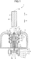
- FIG. 1 is a sectional view illustrating a schematic configuration of a switch according to a first embodiment of the present invention.
- a switch 1 is a grounding switch and placed in an undepicted tank that is filled with an insulating gas having electrical insulating and arc-extinguishing properties, such as sulfur hexafluoride (SF 6 ) gas.
- the switch 1 includes a movable contact 2 that is a first contact, an arc contact 3 that is a second contact, a fixed contact 4 that is a third contact, a shield 5, an engaging part 8, and an engaging mechanism 6.
- SF 6 sulfur hexafluoride
- the movable contact 2 and the arc contact 3 are placed on an identical operation axis 50 and face each other.
- a direction that is parallel with the operation axis 50 and directed from the movable contact 2 toward the arc contact 3 is a first direction and indicated by an arrow X in the drawings.
- a direction that is parallel with the operation axis 50 and directed from the arc contact 3 toward the movable contact 2 is a second direction and indicated by an arrow Y in the drawings.
- the movable contact 2 is placed along the operation axis 50 and configured to reciprocate.
- the movable contact 2 is a conductor having a cylindrical shape, and the operation axis 50 serves as a central axis of the movable contact 2.
- the operation axis 50 serves as a central axis of the movable contact 2.
- the arc contact 3 is retained by a guide part 7 that is made by using a conductor; the arc contact 3 is configured to reciprocate along the operation axis 50.
- a sliding contact 16 that is placed on the guide part 7 maintains electric connection between the arc contact 3 and the guide part 7.
- the arc contact 3 is a conductor having a cylindrical shape and centered on the operation axis 50.
- the arc contact 3 has an end portion 3a that is toward the direction indicated by the arrow Y and that is made of an arc resistant material.
- the guide part 7 surrounds the arc contact 3.
- the arc contact 3 is urged toward the direction indicated by the arrow Y by an urging part 15.
- the urging part 15 is, for example, a compression spring placed between the arc contact 3 and the guide part 7.
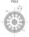
- FIG. 2 is a sectional view illustrating a section along line II-II illustrated in FIG. 1 .
- the fixed contact 4 is placed around the arc contact 3 and centered on the operation axis 50.
- the fixed contact 4 includes a plurality of contact portions 4a, an urging portion 4b, and gap-forming portions 4c.
- the plurality of contact portions 4a is arranged in an annular shape around the arc contact 3 and the guide part 7.
- the urging portion 4b is a spring member that has an annular shape and surrounds the plurality of contact portions 4a from outside; the urging portion 4b urges the plurality of contact portions 4a toward the operation axis 50.
- the gap-forming portion 4c is a member that has an annular shape and is placed inside the plurality of contact portions 4a; the gap-forming portions 4c are in contact with the plurality of contact portions 4a, which is arranged in the annular shape, from inside so as to form a gap between the arc contact 3 and the contact portions 4a.
- the contact portions 4a come into contact with the side face of the movable contact 2.
- the movable contact 2 serves as a main contact on a movable side
- the contact portions 4a serves as a main contact on a fixed side.
- the shield 5 is made of a conductor and accommodates the arc contact 3, the fixed contact 4, and the guide part 7.
- the first opening 5a is provided in an area that includes a portion of the shield 5 that intersects with the operation axis 50.
- the first opening 5a covers a periphery of the end portion 3a of the arc contact 3 in a state illustrated in FIG. 1 .
- the first opening 5a is formed so as to have a size that allows the movable contact 2 and the arc contact 3 to pass therethrough.
- a second opening 5b is formed in a wall surface of the shield 5 located toward the direction indicated by the arrow X.
- the wall surface of the shield 5 located toward the direction indicated by the arrow X is in contact with the guide part 7.
- the engaging part 8 is made using an insulator.
- the engaging part 8 is integrated with the arc contact 3 and placed toward the direction indicated by the arrow X with respect to the arc contact 3.
- the engaging part 8 passes through the second opening 5b, which is formed in the shield 5, and a part of the engaging part 8 is located outside the shield 5.
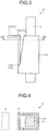
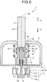
- FIG. 3 is a diagram of the engaging mechanism 6 according to the first embodiment when observed along the direction perpendicular to the operation axis 50.
- FIG. 4 is a sectional view illustrating a section along line IV-IV illustrated in FIG. 3 .
- the engaging mechanism 6 includes a conductor part 9, an attracting part 10 that is a first magnetic material portion, and a part to be attracted 11 that is a second magnetic material part.
- the conductor part 9 is made of a conductor and placed away from the engaging part 8 in the direction perpendicular to the operation axis 50.
- the conductor part 9 is in contact with the shield 5 and electrically connected to the shield 5.
- the attracting part 10 is made of a magnetic material. As illustrated in FIG. 4 , the attracting part 10 has a shape that surrounds the conductor part 9 with a side of the engaging part 8 of the attracting part 10 open.
- the attracting part 10 is secured to the undepicted tank by an undepicted support part that is made of an insulator.
- the attracting part 10 may be secured to, in place of the tank, the conductor part 9 using a screw or an adhesive agent.
- the part to be attracted 11 is made of a magnetic material.
- the part to be attracted 11 is placed between the engaging part 8 and the conductor part 9.
- the part to be attracted 11 is supported on the attracting part 10 by a pivot portion 11a that is placed on an end of the part to be attracted 11 located toward the direction indicated by the arrow X.
- the part to be attracted 11 is pivotable about the pivot portion 11a.
- the part to be attracted 11 is urged in a direction in which an edge portion 11b of the part to be attracted 11 located toward the arrow Y moves to the side of the engaging part 8.
- the urging force is given by, for example, a torsion spring placed at the pivot portion 11a.
- a space is provided between the part to be attracted 11 and the attracting part 10 so as to allow the edge portion 11b of the part to be attracted 11 to move to a side of the attracting part 10.
- An engagement portion 11c that engages with the engaging portion 8 to restrict the engaging portion 8 from moving in the direction indicated by the arrow Y is formed on the edge portion 11b of the part to be attracted 11.
- the part to be attracted 11 restricts the arc contact 3, which is formed integrally with the engaging part 8, from moving in the direction indicated by the arrow Y due to the urging force of the urging part 15.
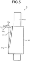
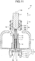
- FIG. 5 is a side view illustrating a state of the engaging mechanism 6 when current flows through the conductor part 9 in the first embodiment.
- an attractive force is generated between the attracting part 10 and the part to be attracted 11 due to a magnetic field generated around the conductor part 9.
- the part to be attracted 11 is thus attracted by the attracting part 10 against the urging force, and moves to the attracting part 10 side as illustrated in FIG. 5 .
- FIGS. 6 to 8 are diagrams for describing the operation of the switch 1 according to the first embodiment.
- the movable contact 2 moves in the direction indicated by the arrow X, and a distance from the arc contact 3 and the shield 5 to the movable contact 2 is reduced.
- a voltage is being applied to the arc contact 3 and the shield 5 at this point in time, an arc 12 is formed between the arc contact 3 and the movable contact 2 or between the shield 5 and the movable contact 2.
- the arc contact 2 thus moves in the direction indicated by the arrow Y, that is, toward the movable contact 2 due to the urging force of the urging part 15, and the end portion 2a of the movable contact 2 and the end portion 3a of the movable contact 3 come into contact with each other in both of the cases when the arc 12 is formed between the movable contact 2 and the arc contact 3 and when the arc 12 is formed between the movable contact 2 and the shield 5.
- the end portion 2a of the movable contact 2 and the end portion 3a of the movable contact 3 come into contact with each other, the arc 12 extinguishes.
- the part to be attracted 11 returns to a position away from the attracting part 10 when the current stops flowing through the conductor part 9.
- the engagement portion 11c is engaged with the engaging part 8 during the process of moving the movable contact 2, and the state illustrated in FIG. 1 in which the movable contact 2 is away from the arc contact 3 is reinstated.
- formation of the arc 12 between the arc contact 3 and the movable contact 2 or between the shield 5 and the movable contact 2 causes the arc contact 3 to move toward the movable contact 2, thereby enabling the movable contact 2 and the arc contact 3 to approach each other after the formation of the arc 12 at a relative velocity resulting from a moving speed of the movable contact 2 and a moving speed of the arc contact 3 added together.
- the duration of the arc 12 formation is desirably reduced.
- the switch 1 according to the first embodiment in which the arc contact 3 is moved toward the movable contact 2, can lower the moving speed of the movable contact 2 in comparison with a configuration in which only the movable contact 2 is moved. That is, the first embodiment can reduce the duration of arc formation and lower the moving speed of the movable contact 2.
- the switch 1 according to the first embodiment can lower the moving speed of the movable contact 2 as described above, thus enabling reduction in size and cost of an undepicted operation device for operating the movable contact and also reduction in size and cost of the switch 1, which includes the operation device.
- a configuration that exerts the urging force to move the part to be attracted 11 away from the attracting part 10 when current stops flowing through the conductor part 9 in the engaging mechanism 6, is not limited to a torsion spring.
- the attracting part 10 and the part to be attracted 11 may be integrally formed.
- the part to be attracted 11 deforms when attracted by the attracting part 10, and a restoring force due to an elastic force of the part to be attracted 11 acts as the urging force when the part to be attracted 11 moves away from the attracting part 10.
- the engaging mechanism 6 may have any configuration as long as it can produce a force to move the part to be attracted 11 away from the attracting part 10 as described above.
- the switch 1 may be used as a disconnect switch other than a grounding switch.
- FIG. 9 is a sectional view illustrating a schematic configuration of a switch according to a second embodiment of the present invention. Parts of a configuration similar to those in the first embodiment described above are designated with similar symbols and their detailed description will be omitted.
- a movable-side main contact 54 that includes contact portions 54a, an urging portion 54b, and gap-forming portions 54c similarly to the fixed contact 4 in the first embodiment is placed as the third contact on the movable contact 2.
- a plurality of contact portions 54a is placed so as to surround the movable contact 2.
- the movable-side main contact 54 moves together with the movable contact 2.
- the guide part 7 is allowed to be inserted into a space inside the contact portions 54a and a side face 7a of the guide part 7 comes into contact with the contact portions 54a.
- the contact portions 54a serve as the main contact on the movable side
- the guide part 7 is a fourth contact that serves as the main contact on the fixed side.
- the opening 5a which is formed in the shield 5, is formed so as to have a size that allows movable-side main contact 54 to pass therethrough.
- FIGS. 10 to 12 are diagrams for describing the operation of the switch 51 according to the second embodiment.
- the arc contact 2 thus moves in the direction indicated by the arrow Y, that is, toward the movable contact 2 due to the urging force of the urging part 15, and the end portion 2a of the movable contact 2 and the end portion 3a of the arc contact 3 come into contact with each other in both of the cases when the arc 12 is formed between the movable contact 2 and the arc contact 3 and when the arc 12 is formed between the movable-side main contact 54 and the shield 5.
- the end portion 2a of the movable contact 2 and the end portion 3a of the arc contact 3 come into contact with each other, the arc 12 extinguishes.
- the movable contact 2 After the end portion 2a of the movable contact 2 and the end portion 3a of the arc contact 3 come into contact with each other, the movable contact 2 further moves in the direction indicated by the arrow X, the arc contact 3 is pushed in the direction indicated by the arrow X against the urging force of the urging part 15 as illustrated in FIG. 12 .
- the guide part 7 When the guide part 7 is inserted into the space inside the contact portions 54a, which are arranged in the annular shape, the side face 7a of the guide part 7 comes into contact with the contact portions 54a of the movable-side main contact 54.
- the switch 51 is a grounding switch, the side face 7a of the guide part 7 and the contact portions 54a of the movable-side main contact 54 come into contact with each other and the grounding is completed.
- the part to be attracted 11 returns to a position away from the attracting part 10 when the current stops flowing through the conductor part 9.
- the movable contact 2 is moved in the direction indicated by the arrow Y from the state illustrated in FIG. 12 , thereby enabling the engagement portion 11c to engage with the engaging part 8 during the process of moving the movable contact 2, and the state illustrated in FIG. 9 in which the movable contact 2 is away from the arc contact 3 is reinstated.
- the second embodiment thus can reduce the duration of arc formation and lower the moving speed of the movable contact 2, as in the case with the first embodiment.
- the second embodiment can also reduce the size and cost of an undepicted operation device for operating the movable contact 2 and reduce the size and cost of the switch 51, which includes the operation device.
Landscapes
- Arc-Extinguishing Devices That Are Switches (AREA)
- Gas-Insulated Switchgears (AREA)
Abstract
Description
- The present invention relates to a switch including a fixed contact and a movable contact.
- A gas-insulated switching apparatus includes switches that each connect and disconnect a circuit by causing a movable contact and a fixed contact to make contact and separate with each other. Such switches include a grounding switch used for grounding a main circuit in equipment inspection. As disclosed in
Patent Literature 1, a movable contact on the grounding side is moved so as to come into contact with a fixed contact on the main circuit side to ground the main circuit. Before the movable contact is placed into contact with the fixed contact, the main circuit is supposed to be disconnected so that no voltage is applied to the fixed contact. - Patent Literature 1: Japanese Patent Application Laid-open No.
2009-163946 - Such switches are in some cases required to accomplish a duty to provide the capability to be turned on safely even when the movable contact is inadvertently brought into contact with the fixed contact while the main circuit is not disconnected and remaining closed. To accomplish this duty, it is necessary to reduce the duration of arc formation between the movable contact and the fixed contact. As a solution, an operation speed of the movable contact has been increased so as to reduce the time from arc formation until the movable contact comes into contact with the fixed contact. For enabling the movable contact to operate quickly, increase in size and cost of an operation device thus causes a problem.
- The present invention has been achieved in view of the above, and an object of the present invention is to provide a switch that reduces the duration of arc formation and lowers an operation speed of a movable contact, thereby enabling reduction in size and cost of an operation device.
- To solve the problem described above and achieve the object described above, a switch according to the present invention includes: a first contact placed so as to be capable of reciprocating in a first direction along an operation axis and in a second direction opposite the first direction; and a second contact placed on a side of the first direction of the first contact so as to be capable of reciprocating in the first direction along the operation axis and in the second direction. When the first direction is a direction from the first contact toward the second contact and the second direction is a direction opposite the first direction, the switch includes an urging part that urges the second contact in the second direction; an engaging part placed integrally with the second contact on the first direction side; and a conductor part placed away from the engaging portion in a direction perpendicular to the operation axis and electrically connected to the second contact. The switch also includes: a first magnetic material part surrounding the conductor part and made of a magnetic material; and a second magnetic material part placed between the first magnetic material part and the engaging part and made of a magnetic material. The second magnetic material part is placed at a position that causes, when no current flows through the conductor part, the second magnetic material part to engage with the engaging part to restrict the second contact from moving in the second direction due to the urging force. A space is provided between the second magnetic material part and the first magnetic material part to allow the second magnetic material part to move to a side of the first magnetic material part. The second magnetic material part moves to the side of the first magnetic material part so as to disengage from the engaging part.
- A switch according to the present invention lowers an operation speed of a movable contact, thereby enabling reduction in size of an operation device and increase in flexibility in design of the operation device.
-
-
FIG. 1 is a sectional view illustrating a schematic configuration of a switch according to a first embodiment of the present invention. -
FIG. 2 is a sectional view illustrating a section along line II-II illustrated inFIG. 1 . -
FIG. 3 is a diagram of an engaging mechanism according to the first embodiment when observed along a direction perpendicular to an operation axis. -
FIG. 4 is a sectional view illustrating a section along line IV-IV illustrated inFIG. 3 . -
FIG. 5 is a side view illustrating a state of the engaging mechanism when current flows through a conductor part in the first embodiment. -
FIG. 6 is a diagram for describing an operation of the switch according to the first embodiment. -
FIG. 7 is a diagram for describing the operation of the switch according to the first embodiment. -
FIG. 8 is a diagram for describing the operation of the switch according to the first embodiment. -
FIG. 9 is a sectional view illustrating a schematic configuration of a switch according to a second embodiment of the present invention. -
FIG. 10 is a diagram for describing an operation of the switch according to the second embodiment. -
FIG. 11 is a diagram for describing the operation of the switch according to the second embodiment. -
FIG. 12 is a diagram for describing the operation of the switch according to the second embodiment. - Exemplary embodiments of a switch according to the present invention is described below in detail with reference to the drawings. The present invention is not limited to the embodiments.
-
FIG. 1 is a sectional view illustrating a schematic configuration of a switch according to a first embodiment of the present invention. Aswitch 1 is a grounding switch and placed in an undepicted tank that is filled with an insulating gas having electrical insulating and arc-extinguishing properties, such as sulfur hexafluoride (SF6) gas. Theswitch 1 includes amovable contact 2 that is a first contact, anarc contact 3 that is a second contact, a fixedcontact 4 that is a third contact, ashield 5, anengaging part 8, and anengaging mechanism 6. - The
movable contact 2 and thearc contact 3 are placed on anidentical operation axis 50 and face each other. In the disclosure below, a direction that is parallel with theoperation axis 50 and directed from themovable contact 2 toward thearc contact 3 is a first direction and indicated by an arrow X in the drawings. A direction that is parallel with theoperation axis 50 and directed from thearc contact 3 toward themovable contact 2 is a second direction and indicated by an arrow Y in the drawings. - The
movable contact 2 is placed along theoperation axis 50 and configured to reciprocate. Themovable contact 2 is a conductor having a cylindrical shape, and theoperation axis 50 serves as a central axis of themovable contact 2. As described below in detail, when themovable contact 2 moves in the direction indicated by the arrow X, anend portion 2a of themovable contact 2 located toward the direction indicated by the arrow X comes into contact with thearc contact 3, and aside face 2b of themovable contact 2 comes into contact with the fixedcontact 4. - The
arc contact 3 is retained by aguide part 7 that is made by using a conductor; thearc contact 3 is configured to reciprocate along theoperation axis 50. A slidingcontact 16 that is placed on theguide part 7 maintains electric connection between thearc contact 3 and theguide part 7. Thearc contact 3 is a conductor having a cylindrical shape and centered on theoperation axis 50. Thearc contact 3 has anend portion 3a that is toward the direction indicated by the arrow Y and that is made of an arc resistant material. Theguide part 7 surrounds thearc contact 3. Thearc contact 3 is urged toward the direction indicated by the arrow Y by anurging part 15. Theurging part 15 is, for example, a compression spring placed between thearc contact 3 and theguide part 7. -
FIG. 2 is a sectional view illustrating a section along line II-II illustrated inFIG. 1 . The fixedcontact 4 is placed around thearc contact 3 and centered on theoperation axis 50. The fixedcontact 4 includes a plurality ofcontact portions 4a, anurging portion 4b, and gap-formingportions 4c. As illustrated inFIG. 2 , the plurality ofcontact portions 4a is arranged in an annular shape around thearc contact 3 and theguide part 7. Theurging portion 4b is a spring member that has an annular shape and surrounds the plurality ofcontact portions 4a from outside; theurging portion 4b urges the plurality ofcontact portions 4a toward theoperation axis 50. The gap-formingportion 4c is a member that has an annular shape and is placed inside the plurality ofcontact portions 4a; the gap-formingportions 4c are in contact with the plurality ofcontact portions 4a, which is arranged in the annular shape, from inside so as to form a gap between thearc contact 3 and thecontact portions 4a. When themovable contact 2 is inserted into a space inside the plurality ofcontact portions 4a, which is arranged in the annular shape, thecontact portions 4a come into contact with the side face of themovable contact 2. In theswitch 1 according to the first embodiment, themovable contact 2 serves as a main contact on a movable side, and thecontact portions 4a serves as a main contact on a fixed side. - The
shield 5 is made of a conductor and accommodates thearc contact 3, the fixedcontact 4, and theguide part 7. In a wall surface of theshield 5 located toward the direction indicated by the arrow Y, thefirst opening 5a is provided in an area that includes a portion of theshield 5 that intersects with theoperation axis 50. Thefirst opening 5a covers a periphery of theend portion 3a of thearc contact 3 in a state illustrated inFIG. 1 . Thefirst opening 5a is formed so as to have a size that allows themovable contact 2 and thearc contact 3 to pass therethrough. - A
second opening 5b is formed in a wall surface of theshield 5 located toward the direction indicated by the arrow X. The wall surface of theshield 5 located toward the direction indicated by the arrow X is in contact with theguide part 7. - The
engaging part 8 is made using an insulator. Theengaging part 8 is integrated with thearc contact 3 and placed toward the direction indicated by the arrow X with respect to thearc contact 3. Theengaging part 8 passes through thesecond opening 5b, which is formed in theshield 5, and a part of theengaging part 8 is located outside theshield 5. - The engaging
mechanism 6 is placed outside theshield 5 away from theengaging part 8 in a direction perpendicular to theoperation axis 50. The engagingmechanism 6 may be illustrated with hatching omitted to facilitate understanding.FIG. 3 is a diagram of the engagingmechanism 6 according to the first embodiment when observed along the direction perpendicular to theoperation axis 50.FIG. 4 is a sectional view illustrating a section along line IV-IV illustrated inFIG. 3 . The engagingmechanism 6 includes aconductor part 9, an attractingpart 10 that is a first magnetic material portion, and a part to be attracted 11 that is a second magnetic material part. - The
conductor part 9 is made of a conductor and placed away from theengaging part 8 in the direction perpendicular to theoperation axis 50. Theconductor part 9 is in contact with theshield 5 and electrically connected to theshield 5. - The attracting
part 10 is made of a magnetic material. As illustrated inFIG. 4 , the attractingpart 10 has a shape that surrounds theconductor part 9 with a side of theengaging part 8 of the attractingpart 10 open. The attractingpart 10 is secured to the undepicted tank by an undepicted support part that is made of an insulator. The attractingpart 10 may be secured to, in place of the tank, theconductor part 9 using a screw or an adhesive agent. - The part to be attracted 11 is made of a magnetic material. The part to be attracted 11 is placed between the
engaging part 8 and theconductor part 9. In the first embodiment, the part to be attracted 11 is supported on the attractingpart 10 by apivot portion 11a that is placed on an end of the part to be attracted 11 located toward the direction indicated by the arrow X. The part to be attracted 11 is pivotable about thepivot portion 11a. The part to be attracted 11 is urged in a direction in which anedge portion 11b of the part to be attracted 11 located toward the arrow Y moves to the side of theengaging part 8. The urging force is given by, for example, a torsion spring placed at thepivot portion 11a. - A space is provided between the part to be attracted 11 and the attracting
part 10 so as to allow theedge portion 11b of the part to be attracted 11 to move to a side of the attractingpart 10. Anengagement portion 11c that engages with the engagingportion 8 to restrict the engagingportion 8 from moving in the direction indicated by the arrow Y is formed on theedge portion 11b of the part to be attracted 11. In other words, the part to be attracted 11 restricts thearc contact 3, which is formed integrally with theengaging part 8, from moving in the direction indicated by the arrow Y due to the urging force of the urgingpart 15. - An operation of the part to be attracted 11 performed when current flows through the
conductor part 9 is described below.FIG. 5 is a side view illustrating a state of the engagingmechanism 6 when current flows through theconductor part 9 in the first embodiment. When current flows through theconductor part 9, an attractive force is generated between the attractingpart 10 and the part to be attracted 11 due to a magnetic field generated around theconductor part 9. The part to be attracted 11 is thus attracted by the attractingpart 10 against the urging force, and moves to the attractingpart 10 side as illustrated inFIG. 5 . When the part to be attracted 11 moves to a side of the attractingpart 10, theengagement portion 11c is disengaged from theengaging part 8, and thearc contact 3 is allowed to move in the direction indicated by the arrow Y due to the urging force of the urgingpart 15. - An operation of the
switch 1 according to the first embodiment from when themovable contact 2 is moved in the direction indicated by the arrow X from a state illustrated inFIG. 1 until when themovable contact 2 and thecontact portions 4a of the fixedcontact 4 come into contact with each other is described next.FIGS. 6 to 8 are diagrams for describing the operation of theswitch 1 according to the first embodiment. - As illustrated in
FIG. 6 , themovable contact 2 moves in the direction indicated by the arrow X, and a distance from thearc contact 3 and theshield 5 to themovable contact 2 is reduced. When a voltage is being applied to thearc contact 3 and theshield 5 at this point in time, anarc 12 is formed between thearc contact 3 and themovable contact 2 or between theshield 5 and themovable contact 2. - When the
arc 12 is formed between themovable contact 2 and thearc contact 3, current flows through apath 13 illustrated inFIG. 6 , that is, the current flows through theconductor part 9 via thearc contact 3, the slidingcontact 16, theguide part 7, and theshield 5. When the current flows through theconductor part 9, the part to be attracted 11 is attracted by the attractingpart 10. Theengagement portion 11c is thus disengaged from theengaging part 8, and thearc contact 3 is allowed to move in the direction indicated by the arrow Y. - When the
arc 12 is formed between themovable contact 2 and theshield 5, current flows through apath 14 illustrated inFIG. 6 , that is, the current flows through theconductor part 9 via theshield 5. When the current flows through theconductor part 9, the part to be attracted 11 is attracted by the attractingpart 10. Theengagement portion 11c is thus disengaged from theengaging part 8, and thearc contact 3 is allowed to move in the direction indicated by the arrow Y. - In other words, current flows through the
conductor part 9 and thearc contact 3 is allowed to move in the direction indicated by the arrow Y in both of the cases when thearc 12 is formed between themovable contact 2 and thearc contact 3 and when thearc 12 is formed between themovable contact 2 and theshield 5. - As illustrated in
FIG. 7 , thearc contact 2 thus moves in the direction indicated by the arrow Y, that is, toward themovable contact 2 due to the urging force of the urgingpart 15, and theend portion 2a of themovable contact 2 and theend portion 3a of themovable contact 3 come into contact with each other in both of the cases when thearc 12 is formed between themovable contact 2 and thearc contact 3 and when thearc 12 is formed between themovable contact 2 and theshield 5. When theend portion 2a of themovable contact 2 and theend portion 3a of themovable contact 3 come into contact with each other, thearc 12 extinguishes. - After the
end portion 2a of themovable contact 2 and theend portion 3a of themovable contact 3 come into contact with each other, when themovable contact 2 further moves in the direction indicated by the arrow X, and thearc contact 3 is pushed in the direction indicated by the arrow X against the urging force of the urgingpart 15 as illustrated inFIG. 8 . Then themovable contact 2 is inserted into the space inside the plurality ofcontact portions 4a which is arranged in the annular shape, and theside face 2b of themovable contact 2 comes into contact with thecontact portions 4a of the fixedcontact 4. When theswitch 1 is a grounding switch, theside face 2b of themovable contact 2 and thecontact portions 4a of the fixedcontact 4 come into contact with each other and the grounding is completed. - After the grounding is completed, the part to be attracted 11 returns to a position away from the attracting
part 10 when the current stops flowing through theconductor part 9. When themovable contact 2 is moved in the direction indicated by the arrow Y from the state illustrated inFIG. 8 , theengagement portion 11c is engaged with theengaging part 8 during the process of moving themovable contact 2, and the state illustrated inFIG. 1 in which themovable contact 2 is away from thearc contact 3 is reinstated. - In the
switch 1 described above, formation of thearc 12 between thearc contact 3 and themovable contact 2 or between theshield 5 and themovable contact 2 causes thearc contact 3 to move toward themovable contact 2, thereby enabling themovable contact 2 and thearc contact 3 to approach each other after the formation of thearc 12 at a relative velocity resulting from a moving speed of themovable contact 2 and a moving speed of thearc contact 3 added together. - To prevent damage to the
movable contact 2 and thearc contact 3 due to thearc 12, the duration of thearc 12 formation is desirably reduced. When the duration of thearc 12 formation required to prevent damage to themovable contact 2 and thearc contact 3 is the same, theswitch 1 according to the first embodiment, in which thearc contact 3 is moved toward themovable contact 2, can lower the moving speed of themovable contact 2 in comparison with a configuration in which only themovable contact 2 is moved. That is, the first embodiment can reduce the duration of arc formation and lower the moving speed of themovable contact 2. - The
switch 1 according to the first embodiment can lower the moving speed of themovable contact 2 as described above, thus enabling reduction in size and cost of an undepicted operation device for operating the movable contact and also reduction in size and cost of theswitch 1, which includes the operation device. - A configuration that exerts the urging force to move the part to be attracted 11 away from the attracting
part 10 when current stops flowing through theconductor part 9 in the engagingmechanism 6, is not limited to a torsion spring. For example, the attractingpart 10 and the part to be attracted 11 may be integrally formed. In this case, the part to be attracted 11 deforms when attracted by the attractingpart 10, and a restoring force due to an elastic force of the part to be attracted 11 acts as the urging force when the part to be attracted 11 moves away from the attractingpart 10. The engagingmechanism 6 may have any configuration as long as it can produce a force to move the part to be attracted 11 away from the attractingpart 10 as described above. Theswitch 1 may be used as a disconnect switch other than a grounding switch. -
FIG. 9 is a sectional view illustrating a schematic configuration of a switch according to a second embodiment of the present invention. Parts of a configuration similar to those in the first embodiment described above are designated with similar symbols and their detailed description will be omitted. In aswitch 51 according to the second embodiment, a movable-sidemain contact 54 that includescontact portions 54a, an urgingportion 54b, and gap-formingportions 54c similarly to the fixedcontact 4 in the first embodiment is placed as the third contact on themovable contact 2. Specifically, a plurality ofcontact portions 54a is placed so as to surround themovable contact 2. - The movable-side
main contact 54 moves together with themovable contact 2. When the movable-sidemain contact 54 moves in the direction indicated by the arrow X, theguide part 7 is allowed to be inserted into a space inside thecontact portions 54a and aside face 7a of theguide part 7 comes into contact with thecontact portions 54a. In other words, in theswitch 51 according to the second embodiment, thecontact portions 54a serve as the main contact on the movable side, and theguide part 7 is a fourth contact that serves as the main contact on the fixed side. - The
opening 5a, which is formed in theshield 5, is formed so as to have a size that allows movable-sidemain contact 54 to pass therethrough. - An operation of the
switch 51 according to the second embodiment from when themovable contact 2 is moved in the direction indicated by the arrow Y from a state illustrated inFIG. 9 until when thecontacts 54a of the movable-sidemain contact 54 and theside face 7a of theguide part 7 are placed into contact with each other is described next.FIGS. 10 to 12 are diagrams for describing the operation of theswitch 51 according to the second embodiment. - As illustrated in
FIG. 10 , when themovable contact 2 moves in the direction indicated by the arrow X, a distance from themovable contact 2 and the movable-sidemain contact 54 to thearc contact 3 is reduced. When a voltage is being applied to thearc contact 3 and theshield 5 at this point in time, anarc 12 is formed between themovable contact 2 and thearc contact 3 or between the movable-sidemain contact 54 and theshield 5. - When the
arc 12 is formed between themovable contact 2 and thearc contact 3, current flows through apath 55 illustrated inFIG. 10 , that is, the current flows through theconductor part 9 via thearc contact 3, the slidingcontact 16, theguide part 7, and theshield 5. When the current flows through theconductor part 9, the part to be attracted 11 is attracted by the attractingpart 10. Thus, theengagement portion 11c is thus disengaged from theengaging part 8, and thearc contact 3 is allowed to move in the direction indicated by the arrow Y. - When the
arc 12 is formed between the movable-sidemain contact 54 and theshield 5, current flows through apath 56 illustrated inFIG. 10 , that is, the current flows through theconductor part 9 via theshield 5. When the current flows through theconductor part 9, the part to be attracted 11 is attracted by the attractingpart 10. Theengagement portion 11c is thus disengaged from theengaging part 8, and thearc contact 3 is allowed to move in the direction indicated by the arrow Y. - In other words, current flows through the
conductor part 9 and thearc contact 3 is allowed to move in the direction indicated by the arrow Y in both of the cases when thearc 12 is formed between themovable contact 2 and thearc contact 3 and when thearc 12 is formed between the movable-sidemain contact 54 and theshield 5. - As illustrated in
FIG. 11 , thearc contact 2 thus moves in the direction indicated by the arrow Y, that is, toward themovable contact 2 due to the urging force of the urgingpart 15, and theend portion 2a of themovable contact 2 and theend portion 3a of thearc contact 3 come into contact with each other in both of the cases when thearc 12 is formed between themovable contact 2 and thearc contact 3 and when thearc 12 is formed between the movable-sidemain contact 54 and theshield 5. When theend portion 2a of themovable contact 2 and theend portion 3a of thearc contact 3 come into contact with each other, thearc 12 extinguishes. - After the
end portion 2a of themovable contact 2 and theend portion 3a of thearc contact 3 come into contact with each other, themovable contact 2 further moves in the direction indicated by the arrow X, thearc contact 3 is pushed in the direction indicated by the arrow X against the urging force of the urgingpart 15 as illustrated inFIG. 12 . When theguide part 7 is inserted into the space inside thecontact portions 54a, which are arranged in the annular shape, theside face 7a of theguide part 7 comes into contact with thecontact portions 54a of the movable-sidemain contact 54. When theswitch 51 is a grounding switch, theside face 7a of theguide part 7 and thecontact portions 54a of the movable-sidemain contact 54 come into contact with each other and the grounding is completed. - After the grounding is completed, the part to be attracted 11 returns to a position away from the attracting
part 10 when the current stops flowing through theconductor part 9. When themovable contact 2 is moved in the direction indicated by the arrow Y from the state illustrated inFIG. 12 , thereby enabling theengagement portion 11c to engage with theengaging part 8 during the process of moving themovable contact 2, and the state illustrated inFIG. 9 in which themovable contact 2 is away from thearc contact 3 is reinstated. - In the
switch 51 described above, formation of thearc 12 causes thearc contact 3 to move toward themovable contact 2, thereby enabling themovable contact 2 and thearc contact 3 to approach each other after the formation of thearc 12 at a relative velocity resulting from a moving speed of themovable contact 2 and a moving speed of thearc contact 3 added together. The second embodiment thus can reduce the duration of arc formation and lower the moving speed of themovable contact 2, as in the case with the first embodiment. The second embodiment can also reduce the size and cost of an undepicted operation device for operating themovable contact 2 and reduce the size and cost of theswitch 51, which includes the operation device. - The configurations in the embodiments described above represent some examples of the present invention, and they can be combined with another publicly known technique and partially omitted or modified without departing from the spirit of the present invention.
- 1 switch; 2 movable contact (first contact); 2a end portion; 2b side face; 3 arc contact (second contact); 3a end portion; 4 fixed contact (third contact); 4a contact portion; 4b urging portion; 4c gap-forming portion; 5 shield; 5a first opening; 5b second opening; 6 engaging mechanism; 7 guide part; 7a side face; 8 engaging part; 9 conductor part; 10 attracting part (first magnetic material part); 11 part to be attracted (second magnetic material part); 11a pivot portion; 11b edge portion; 11c engagement portion; 12 arc; 13, 14 path; 15 urging part; 16 sliding contact; 50 operation axis; 51 switch; 54 movable-side main contact; 54a contact portion; 54b urging portion; 54c gap-forming portion; 55, 56 path.
Claims (4)
- A switch comprising:a first contact placed so as to be capable of reciprocating in a first direction along an operation axis and in a second direction opposite the first direction;a second contact placed on a side of the first direction of the first contact so as to be capable of reciprocating along the operation axis in the first direction and in the second direction;an urging part to urge the second contact in the second direction;an engaging part placed integrally with the second contact on the first direction side of the second contact;a conductor part placed away from the engaging part in a direction perpendicular to the operation axis and electrically connected to the second contact;a first magnetic material part surrounding the conductor part and made of a magnetic material; anda second magnetic material part placed between the first magnetic material part and the engaging part and made of a magnetic material,wherein the second magnetic material part is placed at a position that causes, when no current flows through the conductor part, the second magnetic material part to engage with the engaging part to restrict the second contact from moving in the second direction due to the urging force,a space is provided between the second magnetic material part and the first magnetic material part to allow the second magnetic material part to move to a side of the first magnetic material part, andthe second magnetic material part moves to the first magnetic material part side so as to disengage from the engaging part.
- The switch according to claim 1, further comprising a shield having an opening provided in a portion of the shield that intersects with the operation axis, the opening having a size that allows the first contact and the second contact to pass through the opening, the opening covering a periphery of an end of the second contact located on a side of the second direction when the second magnetic material part engages with the engaging part,
wherein the shield is electrically connected to the conductor part. - The switch according to claim 1, further comprising a third contact centered on the operation axis, placed around the second contact, and urged in a direction approaching the operation axis,
wherein the third contact is capable of coming into contact with a side face of the first contact when the first contact moves in the first direction. - The switch according to claim 1, further comprising: a third contact centered on the operation axis, placed around the first contact, and urged in a direction approaching the operation axis; and
a fourth contact centered on the operation axis and placed around the second contact,
wherein the third contact is capable of coming into contact with a side face of the fourth contact when the first contact moves in the first direction.
Applications Claiming Priority (1)
| Application Number | Priority Date | Filing Date | Title |
|---|---|---|---|
| PCT/JP2016/061270 WO2017175336A1 (en) | 2016-04-06 | 2016-04-06 | Switch |
Publications (3)
| Publication Number | Publication Date |
|---|---|
| EP3441998A1 true EP3441998A1 (en) | 2019-02-13 |
| EP3441998A4 EP3441998A4 (en) | 2019-02-27 |
| EP3441998B1 EP3441998B1 (en) | 2019-10-09 |
Family
ID=57756213
Family Applications (1)
| Application Number | Title | Priority Date | Filing Date |
|---|---|---|---|
| EP16897894.8A Active EP3441998B1 (en) | 2016-04-06 | 2016-04-06 | Switch |
Country Status (4)
| Country | Link |
|---|---|
| US (1) | US10566155B2 (en) |
| EP (1) | EP3441998B1 (en) |
| JP (1) | JP6058230B1 (en) |
| WO (1) | WO2017175336A1 (en) |
Families Citing this family (2)
| Publication number | Priority date | Publication date | Assignee | Title |
|---|---|---|---|---|
| US11069494B2 (en) * | 2017-11-17 | 2021-07-20 | Mitsubishi Electric Corporation | Switchgear |
| CN109616373B (en) * | 2018-12-12 | 2020-07-28 | 西安交通大学 | Vacuum arc-extinguishing chamber composite contact, vacuum arc-extinguishing chamber and vacuum circuit breaker |
Family Cites Families (13)
| Publication number | Priority date | Publication date | Assignee | Title |
|---|---|---|---|---|
| CA1005499A (en) * | 1972-12-11 | 1977-02-15 | Frank S. Nichols | Load break device and arc-extinguishing material therefor |
| DE2935673A1 (en) * | 1978-09-04 | 1980-03-06 | Mitsubishi Electric Corp | SELF-CLEARING SWITCH |
| JPS5755024A (en) | 1980-09-19 | 1982-04-01 | Mitsubishi Electric Corp | Power switching device |
| JPS58165221A (en) * | 1982-03-25 | 1983-09-30 | 三菱電機株式会社 | Disconnecting switch |
| JPH0719504B2 (en) * | 1988-11-08 | 1995-03-06 | 三菱電機株式会社 | Disconnector |
| JP2743740B2 (en) * | 1992-11-05 | 1998-04-22 | 三菱電機株式会社 | Gas insulated switchgear |
| JP3478582B2 (en) * | 1994-01-20 | 2003-12-15 | 株式会社東芝 | Shut-off device |
| JPH07249356A (en) | 1994-03-10 | 1995-09-26 | Meidensha Corp | Gas filled breaker |
| JP4612495B2 (en) * | 2005-07-21 | 2011-01-12 | 株式会社日本Aeパワーシステムズ | Gas insulated switch |
| JP5188176B2 (en) | 2007-12-28 | 2013-04-24 | 三菱電機株式会社 | Ground switch |
| DE102010062343A1 (en) * | 2010-12-02 | 2012-06-06 | Siemens Aktiengesellschaft | Electric contact arrangement |
| JP5389279B2 (en) * | 2011-01-07 | 2014-01-15 | 三菱電機株式会社 | Switchgear |
| JP5629589B2 (en) * | 2011-01-19 | 2014-11-19 | 株式会社東芝 | Switch |
-
2016
- 2016-04-06 US US16/089,165 patent/US10566155B2/en active Active
- 2016-04-06 EP EP16897894.8A patent/EP3441998B1/en active Active
- 2016-04-06 JP JP2016547195A patent/JP6058230B1/en active Active
- 2016-04-06 WO PCT/JP2016/061270 patent/WO2017175336A1/en active Application Filing
Also Published As
| Publication number | Publication date |
|---|---|
| JP6058230B1 (en) | 2017-01-11 |
| JPWO2017175336A1 (en) | 2018-04-12 |
| EP3441998B1 (en) | 2019-10-09 |
| US20190371546A1 (en) | 2019-12-05 |
| WO2017175336A1 (en) | 2017-10-12 |
| US10566155B2 (en) | 2020-02-18 |
| EP3441998A4 (en) | 2019-02-27 |
Similar Documents
| Publication | Publication Date | Title |
|---|---|---|
| KR101581182B1 (en) | Bi-direction Switching Device for using DC current with permanent magnet | |
| EP2996136B1 (en) | Electric vehicle relay | |
| KR101704807B1 (en) | operation device using electromagnetic repulsion force for circuit breaker | |
| EP3441998B1 (en) | Switch | |
| CN107533931B (en) | High-voltage compact fusible disconnect switch device with magnetic arc deflection assembly | |
| US10256058B2 (en) | Switchgear | |
| US10395855B2 (en) | Switch | |
| KR101883432B1 (en) | Vacuum interrupter integrated auxiliary switch | |
| CN109643619B (en) | Switch and method for disconnecting a switch | |
| CN111758142B (en) | Switch with a switch body | |
| EP3690911B1 (en) | Switching device | |
| TWI501280B (en) | Switchgear | |
| CN202816837U (en) | A movable contact bridge and an electric switch device | |
| KR101697627B1 (en) | Gas circuit breaker for gas insulated switchgear | |
| CN103871786A (en) | Electromagnetic contactor | |
| EP3690910B1 (en) | Switch device | |
| US20180019553A1 (en) | Connector | |
| US10734175B1 (en) | High voltage electric power switch with anti-flashover nozzle | |
| EP3185270B1 (en) | Switching device | |
| CN217933496U (en) | Transmission structure and high-voltage electrical apparatus | |
| CN210006628U (en) | Dust-proof arc-extinguishing type auxiliary switch | |
| EP2629313A1 (en) | Gas-insulated circuit breaker with nominal contact shielding arrangement | |
| KR20160130058A (en) | Movable contact of circuit breaker | |
| KR101605138B1 (en) | Disconnecting switch | |
| KR20170008575A (en) | Magnetic switch |
Legal Events
| Date | Code | Title | Description |
|---|---|---|---|
| STAA | Information on the status of an ep patent application or granted ep patent |
Free format text: STATUS: THE INTERNATIONAL PUBLICATION HAS BEEN MADE |
|
| PUAI | Public reference made under article 153(3) epc to a published international application that has entered the european phase |
Free format text: ORIGINAL CODE: 0009012 |
|
| STAA | Information on the status of an ep patent application or granted ep patent |
Free format text: STATUS: REQUEST FOR EXAMINATION WAS MADE |
|
| 17P | Request for examination filed |
Effective date: 20180926 |
|
| AK | Designated contracting states |
Kind code of ref document: A1 Designated state(s): AL AT BE BG CH CY CZ DE DK EE ES FI FR GB GR HR HU IE IS IT LI LT LU LV MC MK MT NL NO PL PT RO RS SE SI SK SM TR |
|
| AX | Request for extension of the european patent |
Extension state: BA ME |
|
| A4 | Supplementary search report drawn up and despatched |
Effective date: 20190124 |
|
| RIC1 | Information provided on ipc code assigned before grant |
Ipc: H01H 33/12 20060101AFI20190118BHEP Ipc: H01H 33/04 20060101ALI20190118BHEP Ipc: H01H 33/64 20060101ALI20190118BHEP |
|
| GRAP | Despatch of communication of intention to grant a patent |
Free format text: ORIGINAL CODE: EPIDOSNIGR1 |
|
| STAA | Information on the status of an ep patent application or granted ep patent |
Free format text: STATUS: GRANT OF PATENT IS INTENDED |
|
| DAV | Request for validation of the european patent (deleted) | ||
| DAX | Request for extension of the european patent (deleted) | ||
| INTG | Intention to grant announced |
Effective date: 20190426 |
|
| GRAS | Grant fee paid |
Free format text: ORIGINAL CODE: EPIDOSNIGR3 |
|
| GRAA | (expected) grant |
Free format text: ORIGINAL CODE: 0009210 |
|
| STAA | Information on the status of an ep patent application or granted ep patent |
Free format text: STATUS: THE PATENT HAS BEEN GRANTED |
|
| AK | Designated contracting states |
Kind code of ref document: B1 Designated state(s): AL AT BE BG CH CY CZ DE DK EE ES FI FR GB GR HR HU IE IS IT LI LT LU LV MC MK MT NL NO PL PT RO RS SE SI SK SM TR |
|
| REG | Reference to a national code |
Ref country code: GB Ref legal event code: FG4D |
|
| REG | Reference to a national code |
Ref country code: CH Ref legal event code: EP |
|
| REG | Reference to a national code |
Ref country code: IE Ref legal event code: FG4D |
|
| REG | Reference to a national code |
Ref country code: DE Ref legal event code: R096 Ref document number: 602016022374 Country of ref document: DE Ref country code: CH Ref legal event code: NV Representative=s name: VALIPAT S.A. C/O BOVARD SA NEUCHATEL, CH |
|
| REG | Reference to a national code |
Ref country code: AT Ref legal event code: REF Ref document number: 1189787 Country of ref document: AT Kind code of ref document: T Effective date: 20191115 |
|
| REG | Reference to a national code |
Ref country code: NL Ref legal event code: MP Effective date: 20191009 |
|
| REG | Reference to a national code |
Ref country code: LT Ref legal event code: MG4D |
|
| REG | Reference to a national code |
Ref country code: AT Ref legal event code: MK05 Ref document number: 1189787 Country of ref document: AT Kind code of ref document: T Effective date: 20191009 |
|
| PG25 | Lapsed in a contracting state [announced via postgrant information from national office to epo] |
Ref country code: NO Free format text: LAPSE BECAUSE OF FAILURE TO SUBMIT A TRANSLATION OF THE DESCRIPTION OR TO PAY THE FEE WITHIN THE PRESCRIBED TIME-LIMIT Effective date: 20200109 Ref country code: AT Free format text: LAPSE BECAUSE OF FAILURE TO SUBMIT A TRANSLATION OF THE DESCRIPTION OR TO PAY THE FEE WITHIN THE PRESCRIBED TIME-LIMIT Effective date: 20191009 Ref country code: PL Free format text: LAPSE BECAUSE OF FAILURE TO SUBMIT A TRANSLATION OF THE DESCRIPTION OR TO PAY THE FEE WITHIN THE PRESCRIBED TIME-LIMIT Effective date: 20191009 Ref country code: FI Free format text: LAPSE BECAUSE OF FAILURE TO SUBMIT A TRANSLATION OF THE DESCRIPTION OR TO PAY THE FEE WITHIN THE PRESCRIBED TIME-LIMIT Effective date: 20191009 Ref country code: BG Free format text: LAPSE BECAUSE OF FAILURE TO SUBMIT A TRANSLATION OF THE DESCRIPTION OR TO PAY THE FEE WITHIN THE PRESCRIBED TIME-LIMIT Effective date: 20200109 Ref country code: LV Free format text: LAPSE BECAUSE OF FAILURE TO SUBMIT A TRANSLATION OF THE DESCRIPTION OR TO PAY THE FEE WITHIN THE PRESCRIBED TIME-LIMIT Effective date: 20191009 Ref country code: SE Free format text: LAPSE BECAUSE OF FAILURE TO SUBMIT A TRANSLATION OF THE DESCRIPTION OR TO PAY THE FEE WITHIN THE PRESCRIBED TIME-LIMIT Effective date: 20191009 Ref country code: GR Free format text: LAPSE BECAUSE OF FAILURE TO SUBMIT A TRANSLATION OF THE DESCRIPTION OR TO PAY THE FEE WITHIN THE PRESCRIBED TIME-LIMIT Effective date: 20200110 Ref country code: PT Free format text: LAPSE BECAUSE OF FAILURE TO SUBMIT A TRANSLATION OF THE DESCRIPTION OR TO PAY THE FEE WITHIN THE PRESCRIBED TIME-LIMIT Effective date: 20200210 Ref country code: ES Free format text: LAPSE BECAUSE OF FAILURE TO SUBMIT A TRANSLATION OF THE DESCRIPTION OR TO PAY THE FEE WITHIN THE PRESCRIBED TIME-LIMIT Effective date: 20191009 Ref country code: LT Free format text: LAPSE BECAUSE OF FAILURE TO SUBMIT A TRANSLATION OF THE DESCRIPTION OR TO PAY THE FEE WITHIN THE PRESCRIBED TIME-LIMIT Effective date: 20191009 Ref country code: NL Free format text: LAPSE BECAUSE OF FAILURE TO SUBMIT A TRANSLATION OF THE DESCRIPTION OR TO PAY THE FEE WITHIN THE PRESCRIBED TIME-LIMIT Effective date: 20191009 |
|
| PG25 | Lapsed in a contracting state [announced via postgrant information from national office to epo] |
Ref country code: HR Free format text: LAPSE BECAUSE OF FAILURE TO SUBMIT A TRANSLATION OF THE DESCRIPTION OR TO PAY THE FEE WITHIN THE PRESCRIBED TIME-LIMIT Effective date: 20191009 Ref country code: IS Free format text: LAPSE BECAUSE OF FAILURE TO SUBMIT A TRANSLATION OF THE DESCRIPTION OR TO PAY THE FEE WITHIN THE PRESCRIBED TIME-LIMIT Effective date: 20200224 Ref country code: RS Free format text: LAPSE BECAUSE OF FAILURE TO SUBMIT A TRANSLATION OF THE DESCRIPTION OR TO PAY THE FEE WITHIN THE PRESCRIBED TIME-LIMIT Effective date: 20191009 |
|
| PG25 | Lapsed in a contracting state [announced via postgrant information from national office to epo] |
Ref country code: AL Free format text: LAPSE BECAUSE OF FAILURE TO SUBMIT A TRANSLATION OF THE DESCRIPTION OR TO PAY THE FEE WITHIN THE PRESCRIBED TIME-LIMIT Effective date: 20191009 |
|
| REG | Reference to a national code |
Ref country code: DE Ref legal event code: R097 Ref document number: 602016022374 Country of ref document: DE |
|
| PG2D | Information on lapse in contracting state deleted |
Ref country code: IS |
|
| PG25 | Lapsed in a contracting state [announced via postgrant information from national office to epo] |
Ref country code: CZ Free format text: LAPSE BECAUSE OF FAILURE TO SUBMIT A TRANSLATION OF THE DESCRIPTION OR TO PAY THE FEE WITHIN THE PRESCRIBED TIME-LIMIT Effective date: 20191009 Ref country code: RO Free format text: LAPSE BECAUSE OF FAILURE TO SUBMIT A TRANSLATION OF THE DESCRIPTION OR TO PAY THE FEE WITHIN THE PRESCRIBED TIME-LIMIT Effective date: 20191009 Ref country code: EE Free format text: LAPSE BECAUSE OF FAILURE TO SUBMIT A TRANSLATION OF THE DESCRIPTION OR TO PAY THE FEE WITHIN THE PRESCRIBED TIME-LIMIT Effective date: 20191009 Ref country code: DK Free format text: LAPSE BECAUSE OF FAILURE TO SUBMIT A TRANSLATION OF THE DESCRIPTION OR TO PAY THE FEE WITHIN THE PRESCRIBED TIME-LIMIT Effective date: 20191009 Ref country code: IS Free format text: LAPSE BECAUSE OF FAILURE TO SUBMIT A TRANSLATION OF THE DESCRIPTION OR TO PAY THE FEE WITHIN THE PRESCRIBED TIME-LIMIT Effective date: 20200209 |
|
| PLBE | No opposition filed within time limit |
Free format text: ORIGINAL CODE: 0009261 |
|
| STAA | Information on the status of an ep patent application or granted ep patent |
Free format text: STATUS: NO OPPOSITION FILED WITHIN TIME LIMIT |
|
| PG25 | Lapsed in a contracting state [announced via postgrant information from national office to epo] |
Ref country code: IT Free format text: LAPSE BECAUSE OF FAILURE TO SUBMIT A TRANSLATION OF THE DESCRIPTION OR TO PAY THE FEE WITHIN THE PRESCRIBED TIME-LIMIT Effective date: 20191009 Ref country code: SM Free format text: LAPSE BECAUSE OF FAILURE TO SUBMIT A TRANSLATION OF THE DESCRIPTION OR TO PAY THE FEE WITHIN THE PRESCRIBED TIME-LIMIT Effective date: 20191009 Ref country code: SK Free format text: LAPSE BECAUSE OF FAILURE TO SUBMIT A TRANSLATION OF THE DESCRIPTION OR TO PAY THE FEE WITHIN THE PRESCRIBED TIME-LIMIT Effective date: 20191009 |
|
| 26N | No opposition filed |
Effective date: 20200710 |
|
| PG25 | Lapsed in a contracting state [announced via postgrant information from national office to epo] |
Ref country code: MC Free format text: LAPSE BECAUSE OF FAILURE TO SUBMIT A TRANSLATION OF THE DESCRIPTION OR TO PAY THE FEE WITHIN THE PRESCRIBED TIME-LIMIT Effective date: 20191009 Ref country code: SI Free format text: LAPSE BECAUSE OF FAILURE TO SUBMIT A TRANSLATION OF THE DESCRIPTION OR TO PAY THE FEE WITHIN THE PRESCRIBED TIME-LIMIT Effective date: 20191009 |
|
| PG25 | Lapsed in a contracting state [announced via postgrant information from national office to epo] |
Ref country code: LU Free format text: LAPSE BECAUSE OF NON-PAYMENT OF DUE FEES Effective date: 20200406 |
|
| REG | Reference to a national code |
Ref country code: BE Ref legal event code: MM Effective date: 20200430 |
|
| PG25 | Lapsed in a contracting state [announced via postgrant information from national office to epo] |
Ref country code: BE Free format text: LAPSE BECAUSE OF NON-PAYMENT OF DUE FEES Effective date: 20200430 |
|
| GBPC | Gb: european patent ceased through non-payment of renewal fee |
Effective date: 20200406 |
|
| PG25 | Lapsed in a contracting state [announced via postgrant information from national office to epo] |
Ref country code: GB Free format text: LAPSE BECAUSE OF NON-PAYMENT OF DUE FEES Effective date: 20200406 Ref country code: IE Free format text: LAPSE BECAUSE OF NON-PAYMENT OF DUE FEES Effective date: 20200406 |
|
| PG25 | Lapsed in a contracting state [announced via postgrant information from national office to epo] |
Ref country code: TR Free format text: LAPSE BECAUSE OF FAILURE TO SUBMIT A TRANSLATION OF THE DESCRIPTION OR TO PAY THE FEE WITHIN THE PRESCRIBED TIME-LIMIT Effective date: 20191009 Ref country code: MT Free format text: LAPSE BECAUSE OF FAILURE TO SUBMIT A TRANSLATION OF THE DESCRIPTION OR TO PAY THE FEE WITHIN THE PRESCRIBED TIME-LIMIT Effective date: 20191009 Ref country code: CY Free format text: LAPSE BECAUSE OF FAILURE TO SUBMIT A TRANSLATION OF THE DESCRIPTION OR TO PAY THE FEE WITHIN THE PRESCRIBED TIME-LIMIT Effective date: 20191009 |
|
| PG25 | Lapsed in a contracting state [announced via postgrant information from national office to epo] |
Ref country code: MK Free format text: LAPSE BECAUSE OF FAILURE TO SUBMIT A TRANSLATION OF THE DESCRIPTION OR TO PAY THE FEE WITHIN THE PRESCRIBED TIME-LIMIT Effective date: 20191009 |
|
| REG | Reference to a national code |
Ref country code: DE Ref legal event code: R084 Ref document number: 602016022374 Country of ref document: DE |
|
| PGFP | Annual fee paid to national office [announced via postgrant information from national office to epo] |
Ref country code: FR Payment date: 20230309 Year of fee payment: 8 |
|
| P01 | Opt-out of the competence of the unified patent court (upc) registered |
Effective date: 20230512 |
|
| PGFP | Annual fee paid to national office [announced via postgrant information from national office to epo] |
Ref country code: DE Payment date: 20230228 Year of fee payment: 8 Ref country code: CH Payment date: 20230501 Year of fee payment: 8 |