EP3441749A1 - Method for observing dynamic physical property of biological tissue, and device for observing dynamic physical property of biological tissue - Google Patents
Method for observing dynamic physical property of biological tissue, and device for observing dynamic physical property of biological tissue Download PDFInfo
- Publication number
- EP3441749A1 EP3441749A1 EP17779151.4A EP17779151A EP3441749A1 EP 3441749 A1 EP3441749 A1 EP 3441749A1 EP 17779151 A EP17779151 A EP 17779151A EP 3441749 A1 EP3441749 A1 EP 3441749A1
- Authority
- EP
- European Patent Office
- Prior art keywords
- biological tissue
- pulsed light
- physical property
- dynamic physical
- observing
- Prior art date
- Legal status (The legal status is an assumption and is not a legal conclusion. Google has not performed a legal analysis and makes no representation as to the accuracy of the status listed.)
- Granted
Links
Images



Classifications
-
- G—PHYSICS
- G01—MEASURING; TESTING
- G01N—INVESTIGATING OR ANALYSING MATERIALS BY DETERMINING THEIR CHEMICAL OR PHYSICAL PROPERTIES
- G01N21/00—Investigating or analysing materials by the use of optical means, i.e. using sub-millimetre waves, infrared, visible or ultraviolet light
- G01N21/17—Systems in which incident light is modified in accordance with the properties of the material investigated
- G01N21/25—Colour; Spectral properties, i.e. comparison of effect of material on the light at two or more different wavelengths or wavelength bands
- G01N21/31—Investigating relative effect of material at wavelengths characteristic of specific elements or molecules, e.g. atomic absorption spectrometry
- G01N21/35—Investigating relative effect of material at wavelengths characteristic of specific elements or molecules, e.g. atomic absorption spectrometry using infrared light
- G01N21/3581—Investigating relative effect of material at wavelengths characteristic of specific elements or molecules, e.g. atomic absorption spectrometry using infrared light using far infrared light; using Terahertz radiation
- G01N21/3586—Investigating relative effect of material at wavelengths characteristic of specific elements or molecules, e.g. atomic absorption spectrometry using infrared light using far infrared light; using Terahertz radiation by Terahertz time domain spectroscopy [THz-TDS]
-
- A—HUMAN NECESSITIES
- A61—MEDICAL OR VETERINARY SCIENCE; HYGIENE
- A61F—FILTERS IMPLANTABLE INTO BLOOD VESSELS; PROSTHESES; DEVICES PROVIDING PATENCY TO, OR PREVENTING COLLAPSING OF, TUBULAR STRUCTURES OF THE BODY, e.g. STENTS; ORTHOPAEDIC, NURSING OR CONTRACEPTIVE DEVICES; FOMENTATION; TREATMENT OR PROTECTION OF EYES OR EARS; BANDAGES, DRESSINGS OR ABSORBENT PADS; FIRST-AID KITS
- A61F2/00—Filters implantable into blood vessels; Prostheses, i.e. artificial substitutes or replacements for parts of the body; Appliances for connecting them with the body; Devices providing patency to, or preventing collapsing of, tubular structures of the body, e.g. stents
- A61F2/02—Prostheses implantable into the body
- A61F2/08—Muscles; Tendons; Ligaments
-
- A—HUMAN NECESSITIES
- A61—MEDICAL OR VETERINARY SCIENCE; HYGIENE
- A61F—FILTERS IMPLANTABLE INTO BLOOD VESSELS; PROSTHESES; DEVICES PROVIDING PATENCY TO, OR PREVENTING COLLAPSING OF, TUBULAR STRUCTURES OF THE BODY, e.g. STENTS; ORTHOPAEDIC, NURSING OR CONTRACEPTIVE DEVICES; FOMENTATION; TREATMENT OR PROTECTION OF EYES OR EARS; BANDAGES, DRESSINGS OR ABSORBENT PADS; FIRST-AID KITS
- A61F2/00—Filters implantable into blood vessels; Prostheses, i.e. artificial substitutes or replacements for parts of the body; Appliances for connecting them with the body; Devices providing patency to, or preventing collapsing of, tubular structures of the body, e.g. stents
- A61F2/02—Prostheses implantable into the body
- A61F2/30—Joints
- A61F2/46—Special tools for implanting artificial joints
- A61F2/468—Testing instruments for artificial joints
-
- A—HUMAN NECESSITIES
- A61—MEDICAL OR VETERINARY SCIENCE; HYGIENE
- A61L—METHODS OR APPARATUS FOR STERILISING MATERIALS OR OBJECTS IN GENERAL; DISINFECTION, STERILISATION OR DEODORISATION OF AIR; CHEMICAL ASPECTS OF BANDAGES, DRESSINGS, ABSORBENT PADS OR SURGICAL ARTICLES; MATERIALS FOR BANDAGES, DRESSINGS, ABSORBENT PADS OR SURGICAL ARTICLES
- A61L27/00—Materials for grafts or prostheses or for coating grafts or prostheses
- A61L27/36—Materials for grafts or prostheses or for coating grafts or prostheses containing ingredients of undetermined constitution or reaction products thereof, e.g. transplant tissue, natural bone, extracellular matrix
- A61L27/3604—Materials for grafts or prostheses or for coating grafts or prostheses containing ingredients of undetermined constitution or reaction products thereof, e.g. transplant tissue, natural bone, extracellular matrix characterised by the human or animal origin of the biological material, e.g. hair, fascia, fish scales, silk, shellac, pericardium, pleura, renal tissue, amniotic membrane, parenchymal tissue, fetal tissue, muscle tissue, fat tissue, enamel
- A61L27/3612—Cartilage, synovial fluid
-
- G—PHYSICS
- G01—MEASURING; TESTING
- G01N—INVESTIGATING OR ANALYSING MATERIALS BY DETERMINING THEIR CHEMICAL OR PHYSICAL PROPERTIES
- G01N21/00—Investigating or analysing materials by the use of optical means, i.e. using sub-millimetre waves, infrared, visible or ultraviolet light
- G01N21/17—Systems in which incident light is modified in accordance with the properties of the material investigated
- G01N21/1717—Systems in which incident light is modified in accordance with the properties of the material investigated with a modulation of one or more physical properties of the sample during the optical investigation, e.g. electro-reflectance
-
- G—PHYSICS
- G01—MEASURING; TESTING
- G01N—INVESTIGATING OR ANALYSING MATERIALS BY DETERMINING THEIR CHEMICAL OR PHYSICAL PROPERTIES
- G01N21/00—Investigating or analysing materials by the use of optical means, i.e. using sub-millimetre waves, infrared, visible or ultraviolet light
- G01N21/17—Systems in which incident light is modified in accordance with the properties of the material investigated
- G01N21/19—Dichroism
-
- G—PHYSICS
- G01—MEASURING; TESTING
- G01N—INVESTIGATING OR ANALYSING MATERIALS BY DETERMINING THEIR CHEMICAL OR PHYSICAL PROPERTIES
- G01N21/00—Investigating or analysing materials by the use of optical means, i.e. using sub-millimetre waves, infrared, visible or ultraviolet light
- G01N21/17—Systems in which incident light is modified in accordance with the properties of the material investigated
- G01N21/21—Polarisation-affecting properties
-
- G—PHYSICS
- G01—MEASURING; TESTING
- G01N—INVESTIGATING OR ANALYSING MATERIALS BY DETERMINING THEIR CHEMICAL OR PHYSICAL PROPERTIES
- G01N33/00—Investigating or analysing materials by specific methods not covered by groups G01N1/00 - G01N31/00
- G01N33/48—Biological material, e.g. blood, urine; Haemocytometers
- G01N33/483—Physical analysis of biological material
- G01N33/4833—Physical analysis of biological material of solid biological material, e.g. tissue samples, cell cultures
-
- A—HUMAN NECESSITIES
- A61—MEDICAL OR VETERINARY SCIENCE; HYGIENE
- A61F—FILTERS IMPLANTABLE INTO BLOOD VESSELS; PROSTHESES; DEVICES PROVIDING PATENCY TO, OR PREVENTING COLLAPSING OF, TUBULAR STRUCTURES OF THE BODY, e.g. STENTS; ORTHOPAEDIC, NURSING OR CONTRACEPTIVE DEVICES; FOMENTATION; TREATMENT OR PROTECTION OF EYES OR EARS; BANDAGES, DRESSINGS OR ABSORBENT PADS; FIRST-AID KITS
- A61F2/00—Filters implantable into blood vessels; Prostheses, i.e. artificial substitutes or replacements for parts of the body; Appliances for connecting them with the body; Devices providing patency to, or preventing collapsing of, tubular structures of the body, e.g. stents
- A61F2/02—Prostheses implantable into the body
- A61F2/30—Joints
- A61F2/30756—Cartilage endoprostheses
- A61F2002/30762—Means for culturing cartilage
-
- A—HUMAN NECESSITIES
- A61—MEDICAL OR VETERINARY SCIENCE; HYGIENE
- A61L—METHODS OR APPARATUS FOR STERILISING MATERIALS OR OBJECTS IN GENERAL; DISINFECTION, STERILISATION OR DEODORISATION OF AIR; CHEMICAL ASPECTS OF BANDAGES, DRESSINGS, ABSORBENT PADS OR SURGICAL ARTICLES; MATERIALS FOR BANDAGES, DRESSINGS, ABSORBENT PADS OR SURGICAL ARTICLES
- A61L2430/00—Materials or treatment for tissue regeneration
- A61L2430/06—Materials or treatment for tissue regeneration for cartilage reconstruction, e.g. meniscus
Definitions
- the present invention relates to a method for observing a dynamic physical property of a biological tissue and a device for observing a dynamic physical property of a biological tissue.
- osteoarthritis As society experiences aging of population, the number of patients suffering from diseases of organs of locomotion as represented by locomotive syndrome, in particular joint diseases has been increasing.
- One of the joint diseases is osteoarthritis. Osteoarthritis is rarely healed spontaneously once a patient develops it, which generally progresses irreversibly and makes it difficult for him/her to walk. Therefore, osteoarthritis is one of the major factors lowering the quality of life of middle-aged and elderly people.
- Regenerated tissue products such as regenerated cartilage involve a unique problem that they cannot be subjected to destruction inspection. As a result, in the current situations, regenerated tissues are transplanted without evaluation of their quality. Accordingly, development of a technique for noninvasively evaluating the regenerated tissues has been sought for.
- Cartilage tissues are composed of chondrocytes and an extracellular matrix.
- macromolecules such as collagen, hyaluronic acid, sulfated glycosaminoglycan exist.
- the extracellular matrix constructs highly hydrated tissues by trapping a lot of water molecules and achieves high viscoelasticity of cartilage tissue and the like.
- Regenerated cartilage uses chondrocytes collected and cultured from a living body and formed by a three-dimensional culture carrier, the chondrocytes, and the matrix produced by the chondrocytes.
- Patent Literature 1 discloses techniques for measuring an object to be measured such as a biopolymer which has been difficult to measure by conventional spectroscopic methods. However, in Patent Literature 1, it has not been possible to evaluate biological tissues such as cartilage tissue and regenerated tissues such as regenerated cartilage.
- the present invention has been made in view of such circumstances, and it is an object of the present invention to provide a technique capable of evaluating biological tissues such as cartilage tissue and regenerated tissues such as regenerated cartilage.
- the present invention provides a method for observing a dynamic physical property of a biological tissue by irradiating the biological tissue with a pulsed light having a wavelength of a far-infrared wavelength region to observe the dynamic physical property of the biological tissue using vibrational optical activity spectroscopy, where the biological tissue is vibrated while the biological tissue is being irradiated with the pulsed light.
- a cartilage tissue is a tissue containing a lot of water. Water molecules trapped in the extracellular matrix exist not as free water but as confined water in a state trapped and oriented in macromolecules such as the extracellular matrix.
- the inventors of the present invention focused on the fact that the confinement of water molecules appears as a viscosity against the deformation due to compressive stress applied to the cartilage tissue, though that the degree of tissue formation and the dynamic physical property of the cartilage tissue could be estimated by measuring the state of the water molecules in the cartilage tissue, and conducted examinations and experimentations.
- Vibration optical activity (abbreviated as VOA) spectroscopy is a scheme for measuring the difference in spectra for left and right circular polarized lights indicated by optically active molecules and examining steric information of molecules together with information on the vibration spectrum.
- a terahertz wave resides in the far-infrared region and has good transmittivity to biological tissues. Since terahertz waves overlap with energy bands of intermolecular vibration and intramolecular vibration, it is possible to obtain information on tissue formation of biological tissues including cartilage tissue.
- the terahertz wave has low photon energy and difficult to detect because it is hidden by noise in intensity or energy spectrum.
- the inventors of the present invention have found that by using vibration optical activity spectroscopy in the terahertz band, it is made possible to obtain a spectrum attributable to the motion modes of water molecules (slow Debye relaxation mode, early Debye relaxation mode, intermolecular stretching vibration mode, and intermolecular declination vibration mode).
- the biological tissue When the biological tissue is irradiated with a pulsed light, the biological tissue is vibrated.
- By forcibly imparting vibration to the biological tissue to cause the biological tissue to vibrate it is made possible to perform spectroscopic measurement in accordance with the vibration frequency for imparting the vibration and gather an increased amount of information on the biological tissue at the molecule level. It is preferable to sweep the vibration frequency within a predetermined range.
- the vibration frequency dependence of the relaxation time can be revealed, which contributes to elucidation of the structure of the biological tissue.
- a radiation means which has a photoconductive film receiving a pulse excitation light and generating a photocarrier and a pair of antenna electrode films formed on the photoconductive film and facing each other via a gap, wherein the radiation means is configured to emit the pulsed light having the wavelength of the far-infrared wavelength region by pulsed laser light irradiation; the biological tissue is irradiated with the pulsed light from the radiation means while vibrating the biological tissue; and the dynamic physical property of the biological tissue is observed based on a vibrational circular dichroism spectrum and/or polarization spectroscopy spectrum obtained from a time-series signal of a reflected pulsed light reflected by the biological tissue or a transmitted pulsed light transmitted through the biological tissue.
- the present invention provides a device for observing a dynamic physical property of a biological tissue.
- the device includes a radiation means including a photoconductive film receiving an excitation pulsed laser light and generating a photocarrier and an antenna electrode film formed on the photoconductive film, and configured to emit a pulsed light having a wavelength of a far-infrared wavelength region by irradiation of the excitation pulsed laser light; a holding means configured to hold the biological tissue; a vibration device configured to vibrate the holding means; a detection means including a photoconductive film and an antenna electrode film and configured to obtain a time-series signal of a reflected pulsed light reflected by the biological tissue or a transmitted pulsed light transmitted through the biological tissue; and a control means configured to observe the dynamic physical property of the biological tissue based on a vibrational circular dichroism spectrum and/or polarization spectroscopy spectrum obtained from a signal obtained from the detection means.
- Vibrations are forcibly imparted to the holding means holding the biological tissue with a vibration device.
- a vibration device By virtue of this, it is made possible to perform spectroscopic measurement in accordance with the vibration frequency for imparting the vibrations and gather information on the biological tissue at the molecule level. It is preferable to sweep the vibration frequency within a predetermined range.
- the vibration frequency dependence of the relaxation time can be revealed, which contributes to the elucidation of the structure of the biological tissue.
- piezoelectric elements such as PZT element may be used.
- the holding means includes a metamaterial.
- the metamaterial is a substance in which minute units called “unit elements” are artificially arranged with equal intervals at distances sufficiently smaller than the wavelength of electromagnetic waves and the metamaterial is configured to behave as a homogeneous medium for electromagnetic waves.
- the present invention it is made possible to provide a technique for observing the degree of tissue formation and dynamic physical property of biological tissues such as cartilage tissue and regenerated tissues such as regenerated cartilage based on vibrational optical activity obtained by using terahertz waves.
- the biological tissue is vibrated while being irradiated with the pulsed light, it is made possible to perform spectroscopic measurement in accordance with the vibration frequency for imparting the vibration and gather an increased amount of information on the biological tissue at the molecule level.
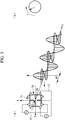
- Fig. 1 illustrates an example of a device for observing a dynamic physical property of a biological tissue according to the present embodiment.
- the device for observing the dynamic physical property of the biological tissue includes a pulsed laser light source 1.
- An ultrashort pulsed laser is used to configure the pulsed laser light source 1.
- the ultrashort pulsed laser may include a femtosecond fiber laser, a femtosecond mode-locked titanium sapphire laser, and the like.
- the femtosecond fiber laser is configured, for example, by an LD-pumped passive mode-locked fiber laser using a 1.55 ⁇ m band erbium (Er) doped fiber laser as a laser gain medium.
- the femtosecond fiber laser may be an ytterbium (Yb) doped fiber with relatively wide band and high quantum effect around 1.06 ⁇ m.
- the femtosecond fiber laser is used, for example, at a center oscillation wavelength (second harmonic output) of 780 nm, a pulse width of 120 to 75 fs (femtoseconds), an average output of 30 mW, and a cyclic frequency of around 40 MHz.
- titanium doped sapphire (Ti:Al 2 O 3 ) crystal is used as the laser medium. Titanium doped sapphire crystal is superior for stable oscillation of femtosecond pulses.
- the femtosecond mode-locked titanium sapphire laser is used, for example, at a central oscillation wavelength of 780 nm, a pulse width of 100 to 45 fs, an average output of 100 mW, and a cyclic frequency of about 40 to 80 MHz.
- the femtosecond fiber laser In comparison with femtosecond mode-locked titanium sapphire laser, the femtosecond fiber laser has superior advantages in practical use in terms of its small size, light weight, simple stable operation, low cost, and low power consumption. On the other hand, the femtosecond mode-locked titanium-sapphire laser has advantages such as relatively wide spectral bandwidth compared with that of the femtosecond fiber laser, excellent ultrashort pulsed light oscillation, and facilitated high-output oscillation.
- the device for observing the dynamic physical property of the biological tissue further includes a beam splitter (splitting means) 2 configured to split the femtosecond laser light (pulsed laser light) L 1 emitted from the pulsed laser light source 1 into pulsed laser light L 2 for use in excitation and pulsed laser light L 3 for use in detection.
- a beam splitter (splitting means) 2 configured to split the femtosecond laser light (pulsed laser light) L 1 emitted from the pulsed laser light source 1 into pulsed laser light L 2 for use in excitation and pulsed laser light L 3 for use in detection.
- the device for observing the dynamic physical property of the biological tissue further includes a terahertz wave generation element (radiation means) 3 configured to emit a pulsed light having a wavelength of a far-infrared wavelength region by irradiation of the pulsed laser light L 2 for excitation and a detection element (detection means) 4 configured to detect a time-series signal of the electric field intensity of a transmitted pulsed light (or reflected pulsed light) from the biological tissue irradiated with the pulsed light from the terahertz wave generation element 3.
- Radio-hemispherical silicon lenses 5, 6 are arranged on the light emission side of the terahertz wave generation element 3 and the light incident side of the detection element 4, respectively, as illustrated in Fig. 1 .
- the terahertz wave generation element 3 and the detection element 4 are photoconductive antenna (abbreviated as PCA) elements.
- the PCA elements include a photoconductive film and an antenna electrode film.
- the photoconductive film is formed, for example, by laminating a thin film of low temperature grown gallium arsenide (abbreviated as LT-GaAs) upon a semi-insulating gallium arsenide (abbreviated as SI-GaAs) substrate.
- LT-GaAs low temperature grown gallium arsenide
- SI-GaAs semi-insulating gallium arsenide
- the antenna electrode film is laminated on the LT-GaAs photoconductive film.
- the material of the antenna electrode film may include gold (Au), etc.
- the antenna electrode film can be formed on the LT-GaAs thin layer by a vapor-deposition technique.
- Fig. 2 is a plan view illustrating a pattern of the antenna electrode film according to the present embodiment.
- the antenna electrode film is configured by a pair of first antenna electrode films 7a arranged to face each other via a gap 8 and a pair of or multiple pairs of second antenna electrode films 7b arranged to face each other via the gap 8.
- the gap 8 is shared by the first antenna electrode films 7a and the second antenna electrode films 7b.
- the pair of second antenna electrode films 7b is arranged with an angle with respect to the pair of first antenna electrode films 7a.
- the second antenna electrode films 7b in a plan view are arranged with an orientation different by substantially 90 degrees with respect to (substantially orthogonal to) the pair of first antenna electrode films 7a.
- the pair of first antenna electrode films 7a and the pair of second antenna electrode films 7b have an orthogonal two-axis structure.
- the first antenna electrode film 7a and the second antenna electrode film 7b are each configured by a conductive transmission channel 9 and a discharge electrode 10.
- the tip of the discharge electrode 10 is oriented toward the gap 8.
- the pattern of the antenna electrode films can be adopted as appropriate depending on the frequency band of the terahertz wave to be emitted.
- the outer-path interval d 1 of the conductive transmission channel 9 is defined as 30 ⁇ m and the gaps d 2 of the discharge electrodes 10 facing each other are both defined as 3 ⁇ m.
- a first lead 11 is connected to the conductive transmission channel 9 of the first antenna electrode film 7a such that voltage can be applied to the pair of first antenna electrode films 7a.
- a second lead 12 is connected to the conductive transmission channel 9 of the second antenna electrode film 7b such that voltage can be applied to the pair of second antenna electrode films 7b.
- the other ends of the first lead and the second lead are connected to the modulation means 13 illustrated in Fig. 1 .
- the modulation means 13 has a voltage generation device (voltage generation unit) capable of applying bias voltage independently to both the first antenna electrode film 7a and the second antenna electrode film 7b.
- the modulation means 13 is capable of receiving signals from the control means 14 and modulating the phase, the amplitude, and the cyclic frequency.
- a holding means 15 configured to hold a biological tissue (sample) is provided in an observation unit optical system 30 between the terahertz wave generation element 3 and the detection element 4.
- biological tissue may include biological tissues such as cartilage tissue and regenerated tissues such as regenerated cartilage.
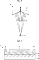
- Fig. 4 illustrates an example of the observation unit optical system 30. It should be noted that, while the optical axis in Fig. 4 extends in the longitudinal direction, which differs from the example illustrated in Fig. 1 , the example of Fig. 4 can also be adopted with its optical axis extending in the width direction as illustrated in Fig. 1 .
- the observation unit optical system 30 is of a Cassegrain type as illustrated in Fig. 4 .
- a primary mirror 31 and a secondary mirror 32 are arranged at the side opposed to the holding means 15 (the upper portion in the same figure). The pulsed light incident from above in the figure is reflected by the secondary mirror 32 and then reflected by the primary mirror 31 and travels toward the holding means 15.
- the focal point resides at the location of the holding means 15, and the biological tissue handled as the sample is arranged at this location.
- the transmitted pulsed light that has transmitted through the biological tissue further transmits through the holding means 15 and travels downward, and is guided to the detection-side optical path. It should be noted that, when the reflected pulsed light that has been reflected by the biological tissue is to be used, the reflected pulsed light is reflected by the primary mirror 31 and the secondary mirror 32, then travels toward the incidence side (the upper portion in the figure) and guided to the detection-side optical path.
- Fig. 5 illustrates a specific configuration of the holding means 15.
- the holding means 15 includes a supporting substrate 40, a metamaterial 41 arranged on the supporting substrate 40, and an insulating film 42 arranged on the metamaterial 41 such as silicon dioxide (SiO 2 ), etc.
- a piezoelectric element (vibration device) 43 such as a PZT element, etc. is provided on the side portion on the insulating film 42.
- the sample (biological tissue) S placed on the insulating film 42 is also illustrated. The sample S is cut into a thickness of several micrometers to several tens of micrometers, for example.
- the metamaterial 41 is a substance in which minute units called “unit elements” are artificially arranged with equal intervals at distances sufficiently smaller than the wavelength of electromagnetic waves and the metamaterial 41 is configured to behave as a homogeneous medium for electromagnetic waves.
- a not-shown power feeding cable and a not-shown control signal cable are connected to the piezoelectric element 43, and the piezoelectric element 43 is controlled by the control means 14.
- the piezoelectric element 43 is configured to be subjected to sweeping in accordance with a command from the control means 14, with a vibration frequency f [kHz] within a predetermined range, for example, from several kilohertz to several hundred hertz.
- the vibration frequency of the piezoelectric element 43 at the time of the measurement is captured in a storage area of the control means 14 along with the elapsed time.
- the piezoelectric elements 43 are provided on both sides of the insulating film 42 in Fig. 5 , the number of the piezoelectric elements may be one or three or more as long as it is capable of imparting vibrations to the sample S, and the locations of installation thereof are not limited to the side portion.
- an optical delay means 16 for time origin adjustment and an optical delay means 17 for time-series signal measurement are arranged on a detection-side optical path extending from the beam splitter 2 to the detection element 4.
- the order of arrangement of the optical delay means 16 for time origin adjustment and the optical delay means 17 for time-series signal measurement may be inverted.
- the optical delay means 16, 17 each include two corner cube mirrors 18.
- the corner cube mirror 18 is fixed to an automatic feeding stage driven along a single axis and configured to change in a stepwise manner (or successively) the length of the light path from the beam splitter 2 to the detection element 4 by virtue of the stage feeding.
- the movement of the stage can be measured by the He-Ne laser 19.
- the optical delay means 16, 17 having the above-described configuration have the characteristic that the length of the light path can be changed two times as large as that in a case of one single corner cube mirror for scanning of the corner cube mirror. Accordingly, the effect achieved by these means is that it is made possible to specify settings for prompt time origin adjustment and the time-series signal measurement.
- a driving device (trigger generation circuit)20 that automatically carries out scanning is connected to the optical delay means 16 for time origin adjustment and the optical delay means 17 for time-series signal measurement, and the control means 14 that automatically controls the driving device 20 is also connected thereto.
- An elliptical mirror (aspherical mirror) 21 and a plane mirror 22 are provided as optical elements on the incidence-side light path between the terahertz wave generation element 3 and the holding means 15.
- the elliptical mirror 21 is configured to concentrate the pulsed light from the terahertz wave generation element 3.
- the plane mirror 22 is arranged in the light path between the terahertz wave generation element 3 and the elliptical mirror 21 and has the redirection function for redirecting the pulsed light from the terahertz wave generation element 3. It should be noted that, while one elliptical mirror 21 and one plane mirror 22 are provided as in the case of the present embodiment, multiple elliptical mirrors 21 and multiple plane mirrors 22 can be used in combination.
- An elliptical mirror (aspherical mirror) 23 and a plane mirror 24 are provided as optical elements on the detection-side optical path between the detection element 4 and the holding means 15.
- the elliptical mirror 23 is configured to concentrate the transmitted pulsed light from the sample.
- the plane mirror 24 is arranged on the light path between the elliptical mirror 23 and the detection element 4, and has the redirection function for redirecting the transmitted pulsed light from the elliptical mirror 23. It should be noted that, while one elliptical mirror 23 and one plane mirror 24 are provided as in the case of the present embodiment, multiple elliptical mirrors 23 and multiple plane mirrors 24 can be used in combination.
- a current voltage conversion means (AVC) 25 is connected to the detection element 4.
- the AVC 25 is configured to convert the current signal that has been detected by the detection element 4 into a voltage signal.
- a control means 14 is connected to the modulation means 13 and the current voltage conversion means 25 directly and via the lock-in amplifier 26.
- the control means 14 is capable of controlling the application of voltage to the antenna electrode films by the modulation means 13.
- the control means 14 includes an analog-to-digital (A/D) converter 14a, an information processing unit 14b, and an input/output unit 14c.
- the information processing unit 14b is configured by, for example, a central processing unit (CPU), a random access memory (RAM), a read only memory (ROM), a computer readable storage medium, and the like.
- CPU central processing unit
- RAM random access memory
- ROM read only memory
- computer readable storage medium and the like.
- the series of processes for realizing the various functions are as an example stored in a storage medium or the like in the form of a program, and the various functions are realized by the CPU reading the program from the RAM or the like and carrying out information processing and arithmetic processing.
- various modes may be implemented for the program, such as a mode according to which the program is installed in advance in the ROM or another storage medium, a mode according to which the program is provided in a state where the program is stored in a computer-readable storage medium, and a mode according to which the program is distributed by wired or wireless communication means.
- the computer-readable storage medium refers to a magnetic disk, a magneto-optical disk, a CD-ROM disc, a DVD-ROM disc, a semiconductor memory, and the like.
- the control means 14 is configured to control the device for observing the dynamic physical property of the biological tissue and has the functions for computing and displaying data acquired by measurements.
- the pulsed laser light L 1 emitted from the pulsed laser light source 1 is split by the beam splitter 2 into the pulsed laser light (pump pulsed light) L 2 for use in excitation and the pulsed laser light (sampling pulsed light) L 3 for use in detection.
- the excitation pulsed laser light L 2 is emitted via the lens 27 to the terahertz wave generation element 3. At this point, the excitation pulsed laser light L 2 is concentrated onto the photoconductive film provided in the gap 8 of the antenna electrode film. In a state where bias voltage is applied to the antenna electrode film, when the photoconductive film is irradiated with the excitation pulsed laser light L 2 , the current due to the light excitation flows instantaneously, and a far-infrared electromagnetic pulse (pulsed light) is emitted.
- the modulation means 13 in accordance with a command issued from the information processing unit 14b, simultaneously applies bias voltages to the first antenna electrode film 7a and the second antenna electrode film 7b, where the bias voltages have the same amplitude and period but the different phases shifted relative to each other, and modulates the pulsed light into a circular polarized light (see (a) and (b) of Fig. 3 ).
- the pulsed light in the form of an elliptically polarized light will be emitted.
- vibrational circular dichroism measurement can be performed.
- the pulsed light after its optical path is redirected by the plane mirror 22, is guided to the elliptical mirror 21 and concentrated so that the sample S is irradiated therewith. At this point, vibrations are forcibly imparted to the sample S by the piezoelectric element 43.
- the control means 14 carries out the sweeping with a vibration frequency f [kHz] within a predetermined range. In the presence of the metamaterial 41, the sample S is irradiated with the pulsed light and accordingly an increased amount of optical information will be transmitted or reflected.
- the transmitted pulsed light that has transmitted the sample S and carries the optical information of the sample is reflected by the elliptical mirror 23 and then redirected by the plane mirror 24, and further guided to the detection element 4. At this point, the reflected or transmitted pulsed light is concentrated onto the photoconductive film residing in the gap 8 of the antenna electrode films.
- the detection pulsed laser light L 3 resulting from the splitting by the beam splitter 2 is given a delay time difference at predetermined time intervals by the optical delay means 16 for time origin adjustment and the optical delay means 17 for time-series signal measurement and guided to the detection element 4.
- the detection pulsed laser light L 3 is concentrated onto the photoconductive film residing in the gap 8 of the antenna electrode films, and superposed on the reflected or transmitted pulsed light of the sample.
- the detection element 4 will exhibit conductivity for the moment during which the photoconductive film is irradiated with the detection pulsed laser light L 3 . Hence, the electric field intensity and the phase lead of the reflected or transmitted pulsed light from the sample to which a trigger is applied and which has arrived at the moment at which the detection element 4 has become conductive are detected as the current signal.
- the current signal that has been detected by the detection element 4 is converted into a voltage signal and amplified by the current voltage conversion means 25 and the voltage signal is sent to the lock-in amplifier 26.
- the pulsed light emitted from the terahertz wave generation element 3 is modulated by the modulation means 13, and the lock-in amplifier 26 uses the cyclic frequency of the modulated pulsed light as the reference signal, picks up only the voltages synchronized with the reference signal using a frequency filter, and the signal is detected with the influence of the background noise decreased.
- the voltage signal that has been amplified by the lock-in amplifier 26 is converted into a digital signal by the A/D converter 14a.
- the information processing unit 14b performs Fourier transformation on the digital signal and calculates the amplitude of the electric field intensity and the spectroscopic spectrum of the phase of the reflected or transmitted pulsed light of the sample.
- the control means 14 obtains the polarization spectrum by standardizing spectroscopic spectra that have been obtained or obtaining the difference of them using the spectrum in a case where the sample does not exist.
- the control means 14 obtains the vibrational circular dichroism spectrum (VCD spectrum) by obtaining the difference of the left and right polarized lights of the spectroscopic spectra that have been obtained.
- the control means 14 can obtain the dynamic physical property of the sample based on the polarization spectrum and the vibrational circular dichroism spectrum that have been obtained, and observe them.
- the dynamic physical property may include elastic modulus ( ⁇ ), dielectric constant ( ⁇ ), relaxation time (T1), refractive index.
- Fig. 6 illustrates a VCD spectrum of an optical rotatory dispersion ⁇ *( ⁇ ) or a circular polarization dichroism ellipticity ⁇ *( ⁇ ) which are examples of optically active amount or optical physical property amount acquired by the above-described device for observing the dynamic physical property of the biological tissue.
- ⁇ represents the wave number.
- the horizontal axis represents time t
- the vertical axis represents the optical rotatory dispersion ⁇ *( ⁇ ) or circular polarization dichroism ellipticity ⁇ *( ⁇ )
- the depth axis represents the wave number ⁇ [cm -1 ].
- the graph illustrated in Fig. 6 can be computed by the control means 14 to be displayed.
- the waveform whose maximum and minimum are conspicuously distinct from each other at the beginning of the measurement is gradually attenuated with the passage of time.
- the relaxation time T can be obtained from the attenuation of the wave numbers ⁇ 1 and o2 representing the maximum value.
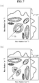
- the synchronous correlation spectrum ( Fig. 7(a) ) and the asynchronous correlation spectrum ( Fig. 7(b) ) are obtained.
- the individual figures in Fig. 7 describe the spectrum of the optical rotatory dispersion ⁇ *( ⁇ ) or the circular polarization dichroism ellipticity ⁇ *( ⁇ ) on the right side and the upper side of the respective graphs.
- the respective graphs illustrated in Fig. 7 can be computed by the control means 14 to be displayed.
- Fig. 7(a) illustrating contour lines of the synchronous correlation spectrum
- the spectrum is symmetrical to the diagonal line D1.
- Fig. 7(b) illustrating the contour lines of the asynchronous correlation spectrum
- the symmetry to the diagonal line D1 is lost.
- the differences of dynamic perturbative variation among multiple biological tissues can be observed as an amount of change appearing in the optically active amount or optical physical property amount.
- the biological tissue When the sample S which is a biological tissue is irradiated with the pulsed light, the biological tissue is vibrated by the piezoelectric element 43.
- the piezoelectric element 43 By forcibly imparting vibrations to the biological tissue to cause the biological tissue to vibrate, it is made possible to perform spectroscopic measurement in accordance with the vibration frequency for imparting the vibrations, and obtain an increased amount of information on the biological tissue at the molecule level.
- the vibration frequency by the piezoelectric element 43 is swept within a predetermined range, it is made possible to identify the structure of a biological molecule in accordance with various frequencies.
- the vibration frequency dependence of the relaxation time T can be revealed, which contributes to the elucidation of the structure of the biological tissue.
Landscapes
- Health & Medical Sciences (AREA)
- Life Sciences & Earth Sciences (AREA)
- Physics & Mathematics (AREA)
- Engineering & Computer Science (AREA)
- Chemical & Material Sciences (AREA)
- General Health & Medical Sciences (AREA)
- Biomedical Technology (AREA)
- Pathology (AREA)
- Immunology (AREA)
- General Physics & Mathematics (AREA)
- Biochemistry (AREA)
- Analytical Chemistry (AREA)
- Spectroscopy & Molecular Physics (AREA)
- Transplantation (AREA)
- Oral & Maxillofacial Surgery (AREA)
- Veterinary Medicine (AREA)
- Public Health (AREA)
- Animal Behavior & Ethology (AREA)
- Orthopedic Medicine & Surgery (AREA)
- Medicinal Chemistry (AREA)
- Molecular Biology (AREA)
- Urology & Nephrology (AREA)
- Heart & Thoracic Surgery (AREA)
- Vascular Medicine (AREA)
- Cardiology (AREA)
- Food Science & Technology (AREA)
- Hematology (AREA)
- Biophysics (AREA)
- Optics & Photonics (AREA)
- Toxicology (AREA)
- Rehabilitation Therapy (AREA)
- Rheumatology (AREA)
- Physical Education & Sports Medicine (AREA)
- Zoology (AREA)
- Botany (AREA)
- Chemical Kinetics & Catalysis (AREA)
- Dermatology (AREA)
- Epidemiology (AREA)
- Investigating Or Analysing Materials By Optical Means (AREA)
Abstract
Description
- The present invention relates to a method for observing a dynamic physical property of a biological tissue and a device for observing a dynamic physical property of a biological tissue.
- As society experiences aging of population, the number of patients suffering from diseases of organs of locomotion as represented by locomotive syndrome, in particular joint diseases has been increasing. One of the joint diseases is osteoarthritis. Osteoarthritis is rarely healed spontaneously once a patient develops it, which generally progresses irreversibly and makes it difficult for him/her to walk. Therefore, osteoarthritis is one of the major factors lowering the quality of life of middle-aged and elderly people.
- From the viewpoint of, for example, maintenance of the patient's quality of life, there has been increasing needs for early diagnosis and early treatment of osteoarthritis. In recent years, as an early treatment of osteoarthritis, treatment by regenerated cartilage transplantation is performed.
- [PTL 1] Japanese Unexamined Patent Application, Publication No.
2001-141567 - Regenerated tissue products such as regenerated cartilage involve a unique problem that they cannot be subjected to destruction inspection. As a result, in the current situations, regenerated tissues are transplanted without evaluation of their quality. Accordingly, development of a technique for noninvasively evaluating the regenerated tissues has been sought for.
- Cartilage tissues are composed of chondrocytes and an extracellular matrix. In the extracellular matrix, macromolecules such as collagen, hyaluronic acid, sulfated glycosaminoglycan exist. The extracellular matrix constructs highly hydrated tissues by trapping a lot of water molecules and achieves high viscoelasticity of cartilage tissue and the like.
- Regenerated cartilage uses chondrocytes collected and cultured from a living body and formed by a three-dimensional culture carrier, the chondrocytes, and the matrix produced by the chondrocytes.
- Living tissues such as cartilage tissue and regenerated tissues such as regenerated cartilage are complex in structure and difficult to analyze.
Patent Literature 1 discloses techniques for measuring an object to be measured such as a biopolymer which has been difficult to measure by conventional spectroscopic methods. However, inPatent Literature 1, it has not been possible to evaluate biological tissues such as cartilage tissue and regenerated tissues such as regenerated cartilage. - The present invention has been made in view of such circumstances, and it is an object of the present invention to provide a technique capable of evaluating biological tissues such as cartilage tissue and regenerated tissues such as regenerated cartilage.
- The present invention provides a method for observing a dynamic physical property of a biological tissue by irradiating the biological tissue with a pulsed light having a wavelength of a far-infrared wavelength region to observe the dynamic physical property of the biological tissue using vibrational optical activity spectroscopy, where the biological tissue is vibrated while the biological tissue is being irradiated with the pulsed light.
- A cartilage tissue is a tissue containing a lot of water. Water molecules trapped in the extracellular matrix exist not as free water but as confined water in a state trapped and oriented in macromolecules such as the extracellular matrix.
- The inventors of the present invention focused on the fact that the confinement of water molecules appears as a viscosity against the deformation due to compressive stress applied to the cartilage tissue, though that the degree of tissue formation and the dynamic physical property of the cartilage tissue could be estimated by measuring the state of the water molecules in the cartilage tissue, and conducted examinations and experimentations.
- Vibration optical activity (abbreviated as VOA) spectroscopy is a scheme for measuring the difference in spectra for left and right circular polarized lights indicated by optically active molecules and examining steric information of molecules together with information on the vibration spectrum.
- A terahertz wave resides in the far-infrared region and has good transmittivity to biological tissues. Since terahertz waves overlap with energy bands of intermolecular vibration and intramolecular vibration, it is possible to obtain information on tissue formation of biological tissues including cartilage tissue.
- The terahertz wave has low photon energy and difficult to detect because it is hidden by noise in intensity or energy spectrum. As a result of intensive research, the inventors of the present invention have found that by using vibration optical activity spectroscopy in the terahertz band, it is made possible to obtain a spectrum attributable to the motion modes of water molecules (slow Debye relaxation mode, early Debye relaxation mode, intermolecular stretching vibration mode, and intermolecular declination vibration mode).
- When the biological tissue is irradiated with a pulsed light, the biological tissue is vibrated. By forcibly imparting vibration to the biological tissue to cause the biological tissue to vibrate, it is made possible to perform spectroscopic measurement in accordance with the vibration frequency for imparting the vibration and gather an increased amount of information on the biological tissue at the molecule level. It is preferable to sweep the vibration frequency within a predetermined range.
- For example, when a relaxation time of the biological tissue is to be obtained as the dynamic physical property, the vibration frequency dependence of the relaxation time can be revealed, which contributes to elucidation of the structure of the biological tissue.
- In accordance with one aspect of the above-described invention, a radiation means is used, which has a photoconductive film receiving a pulse excitation light and generating a photocarrier and a pair of antenna electrode films formed on the photoconductive film and facing each other via a gap, wherein the radiation means is configured to emit the pulsed light having the wavelength of the far-infrared wavelength region by pulsed laser light irradiation; the biological tissue is irradiated with the pulsed light from the radiation means while vibrating the biological tissue; and the dynamic physical property of the biological tissue is observed based on a vibrational circular dichroism spectrum and/or polarization spectroscopy spectrum obtained from a time-series signal of a reflected pulsed light reflected by the biological tissue or a transmitted pulsed light transmitted through the biological tissue.
- In addition, the present invention provides a device for observing a dynamic physical property of a biological tissue. The device includes a radiation means including a photoconductive film receiving an excitation pulsed laser light and generating a photocarrier and an antenna electrode film formed on the photoconductive film, and configured to emit a pulsed light having a wavelength of a far-infrared wavelength region by irradiation of the excitation pulsed laser light; a holding means configured to hold the biological tissue; a vibration device configured to vibrate the holding means; a detection means including a photoconductive film and an antenna electrode film and configured to obtain a time-series signal of a reflected pulsed light reflected by the biological tissue or a transmitted pulsed light transmitted through the biological tissue; and a control means configured to observe the dynamic physical property of the biological tissue based on a vibrational circular dichroism spectrum and/or polarization spectroscopy spectrum obtained from a signal obtained from the detection means.
- Vibrations are forcibly imparted to the holding means holding the biological tissue with a vibration device. By virtue of this, it is made possible to perform spectroscopic measurement in accordance with the vibration frequency for imparting the vibrations and gather information on the biological tissue at the molecule level. It is preferable to sweep the vibration frequency within a predetermined range.
- For example, when a relaxation time of the biological tissue is to be obtained as the dynamic physical property, the vibration frequency dependence of the relaxation time can be revealed, which contributes to the elucidation of the structure of the biological tissue.
- As a device for imparting the vibrations, for example, piezoelectric elements such as PZT element may be used.
- Preferably, it is preferable that the holding means includes a metamaterial. By virtue of this, the measurement sensitivity can be increased. The metamaterial is a substance in which minute units called "unit elements" are artificially arranged with equal intervals at distances sufficiently smaller than the wavelength of electromagnetic waves and the metamaterial is configured to behave as a homogeneous medium for electromagnetic waves.
- According to the present invention, it is made possible to provide a technique for observing the degree of tissue formation and dynamic physical property of biological tissues such as cartilage tissue and regenerated tissues such as regenerated cartilage based on vibrational optical activity obtained by using terahertz waves.
- In addition, since the biological tissue is vibrated while being irradiated with the pulsed light, it is made possible to perform spectroscopic measurement in accordance with the vibration frequency for imparting the vibration and gather an increased amount of information on the biological tissue at the molecule level.
-
-
Fig. 1 is a schematic diagram of a device for observing a dynamic physical property of a biological tissue according to one embodiment of the present invention. -
Fig. 2 is a plan view of a pattern of an antenna electrode film. -
Fig. 3 is a diagram illustrating a polarized pulsed light. -
Fig. 4 is a configuration diagram in which an observation unit optical system is illustrated. -
Fig. 5 is a longitudinal cross-sectional view illustrating a holding means. -
Fig. 6 is a graph illustrating an example of measured data. -
Fig. 7 is a graph obtained by data processing using two-dimensional correlation spectroscopy. -
Fig. 1 illustrates an example of a device for observing a dynamic physical property of a biological tissue according to the present embodiment. - The device for observing the dynamic physical property of the biological tissue includes a pulsed
laser light source 1. An ultrashort pulsed laser is used to configure the pulsedlaser light source 1. The ultrashort pulsed laser may include a femtosecond fiber laser, a femtosecond mode-locked titanium sapphire laser, and the like. - The femtosecond fiber laser is configured, for example, by an LD-pumped passive mode-locked fiber laser using a 1.55 µm band erbium (Er) doped fiber laser as a laser gain medium. The femtosecond fiber laser may be an ytterbium (Yb) doped fiber with relatively wide band and high quantum effect around 1.06 µm.
- The femtosecond fiber laser is used, for example, at a center oscillation wavelength (second harmonic output) of 780 nm, a pulse width of 120 to 75 fs (femtoseconds), an average output of 30 mW, and a cyclic frequency of around 40 MHz.
- In the femtosecond mode-locked titanium sapphire laser, a titanium doped sapphire (Ti:Al2O3) crystal is used as the laser medium. Titanium doped sapphire crystal is superior for stable oscillation of femtosecond pulses.
- The femtosecond mode-locked titanium sapphire laser is used, for example, at a central oscillation wavelength of 780 nm, a pulse width of 100 to 45 fs, an average output of 100 mW, and a cyclic frequency of about 40 to 80 MHz.
- In comparison with femtosecond mode-locked titanium sapphire laser, the femtosecond fiber laser has superior advantages in practical use in terms of its small size, light weight, simple stable operation, low cost, and low power consumption. On the other hand, the femtosecond mode-locked titanium-sapphire laser has advantages such as relatively wide spectral bandwidth compared with that of the femtosecond fiber laser, excellent ultrashort pulsed light oscillation, and facilitated high-output oscillation.
- The device for observing the dynamic physical property of the biological tissue further includes a beam splitter (splitting means) 2 configured to split the femtosecond laser light (pulsed laser light) L1 emitted from the pulsed
laser light source 1 into pulsed laser light L2 for use in excitation and pulsed laser light L3 for use in detection. - The device for observing the dynamic physical property of the biological tissue further includes a terahertz wave generation element (radiation means) 3 configured to emit a pulsed light having a wavelength of a far-infrared wavelength region by irradiation of the pulsed laser light L2 for excitation and a detection element (detection means) 4 configured to detect a time-series signal of the electric field intensity of a transmitted pulsed light (or reflected pulsed light) from the biological tissue irradiated with the pulsed light from the terahertz wave generation element 3.
Super-hemispherical silicon lenses 5, 6 are arranged on the light emission side of the terahertz wave generation element 3 and the light incident side of thedetection element 4, respectively, as illustrated inFig. 1 . - The terahertz wave generation element 3 and the
detection element 4 are photoconductive antenna (abbreviated as PCA) elements. The PCA elements include a photoconductive film and an antenna electrode film. - The photoconductive film is formed, for example, by laminating a thin film of low temperature grown gallium arsenide (abbreviated as LT-GaAs) upon a semi-insulating gallium arsenide (abbreviated as SI-GaAs) substrate.
- The antenna electrode film is laminated on the LT-GaAs photoconductive film. The material of the antenna electrode film may include gold (Au), etc. The antenna electrode film can be formed on the LT-GaAs thin layer by a vapor-deposition technique.
-
Fig. 2 is a plan view illustrating a pattern of the antenna electrode film according to the present embodiment. The antenna electrode film is configured by a pair of firstantenna electrode films 7a arranged to face each other via agap 8 and a pair of or multiple pairs of secondantenna electrode films 7b arranged to face each other via thegap 8. Thegap 8 is shared by the firstantenna electrode films 7a and the secondantenna electrode films 7b. - The pair of second
antenna electrode films 7b is arranged with an angle with respect to the pair of firstantenna electrode films 7a. InFig. 2 , the secondantenna electrode films 7b in a plan view are arranged with an orientation different by substantially 90 degrees with respect to (substantially orthogonal to) the pair of firstantenna electrode films 7a. Specifically, in the antenna electrode film, the pair of firstantenna electrode films 7a and the pair of secondantenna electrode films 7b have an orthogonal two-axis structure. - The first
antenna electrode film 7a and the secondantenna electrode film 7b are each configured by aconductive transmission channel 9 and adischarge electrode 10. The tip of thedischarge electrode 10 is oriented toward thegap 8. - The pattern of the antenna electrode films can be adopted as appropriate depending on the frequency band of the terahertz wave to be emitted. For example, the outer-path interval d1 of the
conductive transmission channel 9 is defined as 30 µm and the gaps d2 of thedischarge electrodes 10 facing each other are both defined as 3 µm. - A
first lead 11 is connected to theconductive transmission channel 9 of the firstantenna electrode film 7a such that voltage can be applied to the pair of firstantenna electrode films 7a. Asecond lead 12 is connected to theconductive transmission channel 9 of the secondantenna electrode film 7b such that voltage can be applied to the pair of secondantenna electrode films 7b. The other ends of the first lead and the second lead are connected to the modulation means 13 illustrated inFig. 1 . - The modulation means 13 has a voltage generation device (voltage generation unit) capable of applying bias voltage independently to both the first
antenna electrode film 7a and the secondantenna electrode film 7b. The modulation means 13 is capable of receiving signals from the control means 14 and modulating the phase, the amplitude, and the cyclic frequency. - A holding means 15 configured to hold a biological tissue (sample) is provided in an observation unit
optical system 30 between the terahertz wave generation element 3 and thedetection element 4. The term "biological tissue" may include biological tissues such as cartilage tissue and regenerated tissues such as regenerated cartilage. -
Fig. 4 illustrates an example of the observation unitoptical system 30. It should be noted that, while the optical axis inFig. 4 extends in the longitudinal direction, which differs from the example illustrated inFig. 1 , the example ofFig. 4 can also be adopted with its optical axis extending in the width direction as illustrated inFig. 1 . The observation unitoptical system 30 is of a Cassegrain type as illustrated inFig. 4 . Aprimary mirror 31 and asecondary mirror 32 are arranged at the side opposed to the holding means 15 (the upper portion in the same figure). The pulsed light incident from above in the figure is reflected by thesecondary mirror 32 and then reflected by theprimary mirror 31 and travels toward the holding means 15. The focal point resides at the location of the holding means 15, and the biological tissue handled as the sample is arranged at this location. The transmitted pulsed light that has transmitted through the biological tissue further transmits through the holding means 15 and travels downward, and is guided to the detection-side optical path. It should be noted that, when the reflected pulsed light that has been reflected by the biological tissue is to be used, the reflected pulsed light is reflected by theprimary mirror 31 and thesecondary mirror 32, then travels toward the incidence side (the upper portion in the figure) and guided to the detection-side optical path. -
Fig. 5 illustrates a specific configuration of the holding means 15. As illustrated in this figure, the holding means 15 includes a supportingsubstrate 40, ametamaterial 41 arranged on the supportingsubstrate 40, and an insulatingfilm 42 arranged on themetamaterial 41 such as silicon dioxide (SiO2), etc. Also, a piezoelectric element (vibration device) 43 such as a PZT element, etc. is provided on the side portion on the insulatingfilm 42. In the same figure, the sample (biological tissue) S placed on the insulatingfilm 42 is also illustrated. The sample S is cut into a thickness of several micrometers to several tens of micrometers, for example. - The
metamaterial 41 is a substance in which minute units called "unit elements" are artificially arranged with equal intervals at distances sufficiently smaller than the wavelength of electromagnetic waves and themetamaterial 41 is configured to behave as a homogeneous medium for electromagnetic waves. - A not-shown power feeding cable and a not-shown control signal cable are connected to the
piezoelectric element 43, and thepiezoelectric element 43 is controlled by the control means 14. Thepiezoelectric element 43 is configured to be subjected to sweeping in accordance with a command from the control means 14, with a vibration frequency f [kHz] within a predetermined range, for example, from several kilohertz to several hundred hertz. The vibration frequency of thepiezoelectric element 43 at the time of the measurement is captured in a storage area of the control means 14 along with the elapsed time. It should be noted that, while thepiezoelectric elements 43 are provided on both sides of the insulatingfilm 42 inFig. 5 , the number of the piezoelectric elements may be one or three or more as long as it is capable of imparting vibrations to the sample S, and the locations of installation thereof are not limited to the side portion. - As illustrated in
Fig. 1 , an optical delay means 16 for time origin adjustment and an optical delay means 17 for time-series signal measurement are arranged on a detection-side optical path extending from thebeam splitter 2 to thedetection element 4. The order of arrangement of the optical delay means 16 for time origin adjustment and the optical delay means 17 for time-series signal measurement may be inverted. - The optical delay means 16, 17 each include two corner cube mirrors 18. The
corner cube mirror 18 is fixed to an automatic feeding stage driven along a single axis and configured to change in a stepwise manner (or successively) the length of the light path from thebeam splitter 2 to thedetection element 4 by virtue of the stage feeding. The movement of the stage can be measured by the He-Ne laser 19. - The optical delay means 16, 17 having the above-described configuration have the characteristic that the length of the light path can be changed two times as large as that in a case of one single corner cube mirror for scanning of the corner cube mirror. Accordingly, the effect achieved by these means is that it is made possible to specify settings for prompt time origin adjustment and the time-series signal measurement.
- A driving device (trigger generation circuit)20 that automatically carries out scanning is connected to the optical delay means 16 for time origin adjustment and the optical delay means 17 for time-series signal measurement, and the control means 14 that automatically controls the driving
device 20 is also connected thereto. - An elliptical mirror (aspherical mirror) 21 and a
plane mirror 22 are provided as optical elements on the incidence-side light path between the terahertz wave generation element 3 and the holding means 15. Theelliptical mirror 21 is configured to concentrate the pulsed light from the terahertz wave generation element 3. Theplane mirror 22 is arranged in the light path between the terahertz wave generation element 3 and theelliptical mirror 21 and has the redirection function for redirecting the pulsed light from the terahertz wave generation element 3. It should be noted that, while oneelliptical mirror 21 and oneplane mirror 22 are provided as in the case of the present embodiment, multipleelliptical mirrors 21 and multiple plane mirrors 22 can be used in combination. - An elliptical mirror (aspherical mirror) 23 and a
plane mirror 24 are provided as optical elements on the detection-side optical path between thedetection element 4 and the holding means 15. Theelliptical mirror 23 is configured to concentrate the transmitted pulsed light from the sample. Theplane mirror 24 is arranged on the light path between theelliptical mirror 23 and thedetection element 4, and has the redirection function for redirecting the transmitted pulsed light from theelliptical mirror 23. It should be noted that, while oneelliptical mirror 23 and oneplane mirror 24 are provided as in the case of the present embodiment, multipleelliptical mirrors 23 and multiple plane mirrors 24 can be used in combination. - A current voltage conversion means (AVC) 25 is connected to the
detection element 4. TheAVC 25 is configured to convert the current signal that has been detected by thedetection element 4 into a voltage signal. - A control means 14 is connected to the modulation means 13 and the current voltage conversion means 25 directly and via the lock-in
amplifier 26. The control means 14 is capable of controlling the application of voltage to the antenna electrode films by the modulation means 13. - The control means 14 includes an analog-to-digital (A/D)
converter 14a, aninformation processing unit 14b, and an input/output unit 14c. Theinformation processing unit 14b is configured by, for example, a central processing unit (CPU), a random access memory (RAM), a read only memory (ROM), a computer readable storage medium, and the like. In addition, the series of processes for realizing the various functions are as an example stored in a storage medium or the like in the form of a program, and the various functions are realized by the CPU reading the program from the RAM or the like and carrying out information processing and arithmetic processing. It should be noted that various modes may be implemented for the program, such as a mode according to which the program is installed in advance in the ROM or another storage medium, a mode according to which the program is provided in a state where the program is stored in a computer-readable storage medium, and a mode according to which the program is distributed by wired or wireless communication means. The computer-readable storage medium refers to a magnetic disk, a magneto-optical disk, a CD-ROM disc, a DVD-ROM disc, a semiconductor memory, and the like. - The control means 14 is configured to control the device for observing the dynamic physical property of the biological tissue and has the functions for computing and displaying data acquired by measurements.
- Next, the operation of the device for observing the dynamic physical property of the biological tissue according to the present embodiment will be described.
- The pulsed laser light L1 emitted from the pulsed
laser light source 1 is split by thebeam splitter 2 into the pulsed laser light (pump pulsed light) L2 for use in excitation and the pulsed laser light (sampling pulsed light) L3 for use in detection. - The excitation pulsed laser light L2 is emitted via the
lens 27 to the terahertz wave generation element 3. At this point, the excitation pulsed laser light L2 is concentrated onto the photoconductive film provided in thegap 8 of the antenna electrode film. In a state where bias voltage is applied to the antenna electrode film, when the photoconductive film is irradiated with the excitation pulsed laser light L2, the current due to the light excitation flows instantaneously, and a far-infrared electromagnetic pulse (pulsed light) is emitted. - At this point, the modulation means 13, in accordance with a command issued from the
information processing unit 14b, simultaneously applies bias voltages to the firstantenna electrode film 7a and the secondantenna electrode film 7b, where the bias voltages have the same amplitude and period but the different phases shifted relative to each other, and modulates the pulsed light into a circular polarized light (see (a) and (b) ofFig. 3 ). - When not only the phase but the amplitude of the sinusoidal voltage applied to the second
antenna electrode film 7b are differentiated, the pulsed light in the form of an elliptically polarized light will be emitted. By such a use, vibrational circular dichroism measurement can be performed. - The pulsed light, after its optical path is redirected by the
plane mirror 22, is guided to theelliptical mirror 21 and concentrated so that the sample S is irradiated therewith. At this point, vibrations are forcibly imparted to the sample S by thepiezoelectric element 43. The control means 14 carries out the sweeping with a vibration frequency f [kHz] within a predetermined range. In the presence of themetamaterial 41, the sample S is irradiated with the pulsed light and accordingly an increased amount of optical information will be transmitted or reflected. - The transmitted pulsed light that has transmitted the sample S and carries the optical information of the sample (or a reflected pulsed light that has been reflected by the sample) is reflected by the
elliptical mirror 23 and then redirected by theplane mirror 24, and further guided to thedetection element 4. At this point, the reflected or transmitted pulsed light is concentrated onto the photoconductive film residing in thegap 8 of the antenna electrode films. - The detection pulsed laser light L3 resulting from the splitting by the
beam splitter 2 is given a delay time difference at predetermined time intervals by the optical delay means 16 for time origin adjustment and the optical delay means 17 for time-series signal measurement and guided to thedetection element 4. At this point, the detection pulsed laser light L3 is concentrated onto the photoconductive film residing in thegap 8 of the antenna electrode films, and superposed on the reflected or transmitted pulsed light of the sample. - The
detection element 4 will exhibit conductivity for the moment during which the photoconductive film is irradiated with the detection pulsed laser light L3. Hence, the electric field intensity and the phase lead of the reflected or transmitted pulsed light from the sample to which a trigger is applied and which has arrived at the moment at which thedetection element 4 has become conductive are detected as the current signal. - The current signal that has been detected by the
detection element 4 is converted into a voltage signal and amplified by the current voltage conversion means 25 and the voltage signal is sent to the lock-inamplifier 26. The pulsed light emitted from the terahertz wave generation element 3 is modulated by the modulation means 13, and the lock-inamplifier 26 uses the cyclic frequency of the modulated pulsed light as the reference signal, picks up only the voltages synchronized with the reference signal using a frequency filter, and the signal is detected with the influence of the background noise decreased. - The voltage signal that has been amplified by the lock-in
amplifier 26 is converted into a digital signal by the A/D converter 14a. Theinformation processing unit 14b performs Fourier transformation on the digital signal and calculates the amplitude of the electric field intensity and the spectroscopic spectrum of the phase of the reflected or transmitted pulsed light of the sample. - The control means 14 obtains the polarization spectrum by standardizing spectroscopic spectra that have been obtained or obtaining the difference of them using the spectrum in a case where the sample does not exist. The control means 14 obtains the vibrational circular dichroism spectrum (VCD spectrum) by obtaining the difference of the left and right polarized lights of the spectroscopic spectra that have been obtained. The control means 14 can obtain the dynamic physical property of the sample based on the polarization spectrum and the vibrational circular dichroism spectrum that have been obtained, and observe them. The dynamic physical property may include elastic modulus (η), dielectric constant (ε), relaxation time (T1), refractive index.
-
Fig. 6 illustrates a VCD spectrum of an optical rotatory dispersion α*(σ) or a circular polarization dichroism ellipticity θ*(σ) which are examples of optically active amount or optical physical property amount acquired by the above-described device for observing the dynamic physical property of the biological tissue. Here, σ represents the wave number. In this figure, the horizontal axis represents time t, the vertical axis represents the optical rotatory dispersion α*(σ) or circular polarization dichroism ellipticity θ*(σ), and the depth axis represents the wave number σ[cm-1]. The graph illustrated inFig. 6 can be computed by the control means 14 to be displayed. - As can be appreciated from the same figure, the waveform whose maximum and minimum are conspicuously distinct from each other at the beginning of the measurement is gradually attenuated with the passage of time. And the relaxation time T can be obtained from the attenuation of the wave numbers σ1 and o2 representing the maximum value. For example, the relaxation time T of the optical rotatory dispersion α*(σ) can be obtained from the following expression:

- Next, data processing using the two-dimensional correlation spectroscopy will be described. For the general understanding of the two-dimensional correlation spectroscopy, "Experimental Infrared Spectroscopy Fundamentals and Practical Methods" (written and edited by Mitsuo Tasumi, Spectroscopical Society of Japan; S.T. Japan INC. April 2012), "Part II ) may be referred to. The data illustrated in
Fig. 6 is obtained for each frequency used when the sample S is vibrated with the vibration frequency f[kHz] by thepiezoelectric element 43. By virtue of this, the optically active amount can be measured in accordance with the vibration frequency f. - In addition, as illustrated in
Fig. 7 , the synchronous correlation spectrum (Fig. 7(a) ) and the asynchronous correlation spectrum (Fig. 7(b) ) are obtained. The individual figures inFig. 7 describe the spectrum of the optical rotatory dispersion α*(σ) or the circular polarization dichroism ellipticity θ*(σ) on the right side and the upper side of the respective graphs. The respective graphs illustrated inFig. 7 can be computed by the control means 14 to be displayed. - Referring to
Fig. 7(a) illustrating contour lines of the synchronous correlation spectrum, the spectrum is symmetrical to the diagonal line D1. In contrast, referring toFig. 7(b) illustrating the contour lines of the asynchronous correlation spectrum, it can be seen that the symmetry to the diagonal line D1 is lost. In view of this, it is possible to determine that a certain structural change has occurred with a certain wave number in the particular vibration frequency f. In this manner, it is made possible to provide the basic data for elucidating the structure related, for example, to water molecule of the biological tissue. - As has been discussed in the foregoing, by externally and forcibly imparting vibrations to give the elastic wave, the differences of dynamic perturbative variation among multiple biological tissues can be observed as an amount of change appearing in the optically active amount or optical physical property amount.
- According to the present embodiment, the following effects can be obtained.
- When the sample S which is a biological tissue is irradiated with the pulsed light, the biological tissue is vibrated by the
piezoelectric element 43. By forcibly imparting vibrations to the biological tissue to cause the biological tissue to vibrate, it is made possible to perform spectroscopic measurement in accordance with the vibration frequency for imparting the vibrations, and obtain an increased amount of information on the biological tissue at the molecule level. - Since the vibration frequency by the
piezoelectric element 43 is swept within a predetermined range, it is made possible to identify the structure of a biological molecule in accordance with various frequencies. - When the relaxation time T of the biological tissue is to be obtained as the dynamic physical property, the vibration frequency dependence of the relaxation time T can be revealed, which contributes to the elucidation of the structure of the biological tissue.
-
- 1
- pulsed laser light source
- 2
- beam splitter (splitting means)
- 3
- terahertz wave generation element (radiation means)
- 4
- detection element (detection means)
- 5, 6
- super-hemispherical silicon lens
- 7a
- first antenna electrode film
- 7b
- second antenna electrode film
- 8
- gap
- 9
- conductive transmission channel
- 10
- discharge electrode
- 11
- first lead
- 12
- second lead
- 13
- modulation means
- 14
- control means
- 14a
- A/D converter
- 14b
- information processing unit
- 14c
- input/output unit
- 15
- holding means
- 16
- optical delay means (for time origin adjustment)
- 17
- optical delay means (for time-series signal measurement)
- 18
- corner cube mirror
- 19
- He-Ne laser
- 20
- driving device (trigger generation circuit)
- 21, 23
- elliptical mirror (aspherical mirror)
- 22, 24
- plane mirror
- 25
- current voltage conversion means
- 26
- lock-in amplifier
- 27
- lens
- 30
- observation unit optical system
- 41
- metamaterial
- 43
- piezoelectric element (vibration device)
- S
- sample (biological tissue)
Claims (3)
- A method for observing a dynamic physical property of a biological tissue by irradiating the biological tissue with a pulsed light having a wavelength of a far-infrared wavelength region to observe the dynamic physical property of the biological tissue using vibrational optical activity spectroscopy, the method comprising vibrating the biological tissue when the biological tissue is irradiated with the pulsed light.
- The method for observing the dynamic physical property of the biological tissue according to claim 1, the method comprising:using a radiation means havinga photoconductive film receiving a pulse excitation light and generating a photocarrier anda pair of antenna electrode films formed on the photoconductive film and facing each other via a gap, andbeing configured to emit the pulsed light having the wavelength of the far-infrared wavelength region by pulsed laser light irradiation;irradiating the biological tissue with the pulsed light from the radiation means while vibrating the biological tissue; andobserving the dynamic physical property of the biological tissue based on a vibrational circular dichroism spectrum and/or polarization spectroscopy spectrum obtained from a time-series signal of a reflected pulsed light reflected by the biological tissue or a transmitted pulsed light transmitted through the biological tissue.
- A device for observing a dynamic physical property of a biological tissue, the device comprisinga radiation means includinga photoconductive film receiving an excitation pulsed laser light and generating a photocarrier andan antenna electrode film formed on the photoconductive film, andconfigured to emit a pulsed light having a wavelength of a far-infrared wavelength region by irradiation of the excitation pulsed laser light;a holding means configured to hold the biological tissue;a vibration device configured to vibrate the holding means;a detection means including a photoconductive film and an antenna electrode film and configured to obtain a time-series signal of a reflected pulsed light reflected by the biological tissue or a transmitted pulsed light transmitted through the biological tissue; anda control means configured to observe the dynamic physical property of the biological tissue based on a vibrational circular dichroism spectrum and/or polarization spectroscopy spectrum obtained from a signal obtained from the detection means.
Applications Claiming Priority (2)
| Application Number | Priority Date | Filing Date | Title |
|---|---|---|---|
| JP2016075572 | 2016-04-05 | ||
| PCT/JP2017/014149 WO2017175773A1 (en) | 2016-04-05 | 2017-04-04 | Method for observing dynamic physical property of biological tissue, and device for observing dynamic physical property of biological tissue |
Publications (3)
| Publication Number | Publication Date |
|---|---|
| EP3441749A1 true EP3441749A1 (en) | 2019-02-13 |
| EP3441749A4 EP3441749A4 (en) | 2019-12-18 |
| EP3441749B1 EP3441749B1 (en) | 2023-11-22 |
Family
ID=60000472
Family Applications (1)
| Application Number | Title | Priority Date | Filing Date |
|---|---|---|---|
| EP17779151.4A Active EP3441749B1 (en) | 2016-04-05 | 2017-04-04 | Method for observing dynamic physical property of biological tissue, and device for observing dynamic physical property of biological tissue |
Country Status (4)
| Country | Link |
|---|---|
| US (1) | US20190128804A1 (en) |
| EP (1) | EP3441749B1 (en) |
| JP (1) | JP6799295B2 (en) |
| WO (1) | WO2017175773A1 (en) |
Families Citing this family (2)
| Publication number | Priority date | Publication date | Assignee | Title |
|---|---|---|---|---|
| EP4046684B1 (en) * | 2021-02-23 | 2023-08-23 | Medizinisches Laserzentrum Lübeck GmbH | Biological tissue treatment apparatus |
| EP4300059B1 (en) * | 2021-02-25 | 2025-05-21 | Inter-University Research Institute Corporation National Institutes of Natural Sciences | Circularly polarized light illuminator, analysis device, and microscope |
Family Cites Families (8)
| Publication number | Priority date | Publication date | Assignee | Title |
|---|---|---|---|---|
| JP3922462B2 (en) * | 2004-09-30 | 2007-05-30 | 独立行政法人科学技術振興機構 | Infrared light emitting device, time-series conversion pulse spectroscopic measuring device, and infrared light emitting method |
| WO2006035780A1 (en) * | 2004-09-30 | 2006-04-06 | Japan Science And Technology Agency | Infrared light radiation device, infrared light detection device, time-series conversion pulse spectrometer, and infrared light radiation method |
| US7456956B2 (en) * | 2006-03-21 | 2008-11-25 | Thermo Electron Scientific Instruments Llc | Vibrational circular dichroism spectrometer using reflective optics |
| JP5643329B2 (en) * | 2009-11-18 | 2014-12-17 | ザ リージェンツ オブ ザ ユニバーシティ オブ カリフォルニア | Multiple pulse impulsive stimulated Raman spectroscopy apparatus and measurement method |
| JP5722094B2 (en) * | 2011-03-25 | 2015-05-20 | 日本分光株式会社 | Circular dichroism measuring apparatus and circular dichroism measuring method |
| GB201116518D0 (en) * | 2011-09-23 | 2011-11-09 | Isis Innovation | Investigation of physical properties of an object |
| US9804026B2 (en) * | 2012-01-23 | 2017-10-31 | The Regents Of The University Of Michigan | Photoconductive emitter device with plasmonic electrodes |
| JP2013195176A (en) * | 2012-03-19 | 2013-09-30 | Canon Inc | Electromagnetic wave pulse measuring device, electromagnetic wave pulse measuring method, and application device using electromagnetic wave pulse measuring device |
-
2017
- 2017-04-04 EP EP17779151.4A patent/EP3441749B1/en active Active
- 2017-04-04 JP JP2018510621A patent/JP6799295B2/en active Active
- 2017-04-04 WO PCT/JP2017/014149 patent/WO2017175773A1/en not_active Ceased
- 2017-04-20 US US16/091,534 patent/US20190128804A1/en not_active Abandoned
Also Published As
| Publication number | Publication date |
|---|---|
| US20190128804A1 (en) | 2019-05-02 |
| EP3441749B1 (en) | 2023-11-22 |
| JP6799295B2 (en) | 2020-12-16 |
| WO2017175773A1 (en) | 2017-10-12 |
| JPWO2017175773A1 (en) | 2019-05-16 |
| EP3441749A4 (en) | 2019-12-18 |
Similar Documents
| Publication | Publication Date | Title |
|---|---|---|
| US20250123147A1 (en) | Systems and methods for stimulated brillouin microscopy | |
| US6466806B1 (en) | Photoacoustic material analysis | |
| US10718708B2 (en) | Method for observing dynamic physical property of biological tissue and device for observing dynamic physical property of biological tissue | |
| US8681331B2 (en) | Systems and methods providing efficient detection of back-scattered illumination in modulation transfer microscopy or micro-spectroscopy | |
| EP2203733B1 (en) | Confocal photoacoustic microscopy with optical lateral resolution | |
| US20070015992A1 (en) | System and method for optoacoustic imaging | |
| CN109374134A (en) | Ultrafast time-resolved transient reflectance spectroscopy imaging system | |
| JP2003525447A (en) | Imaging device and method | |
| CN113552071A (en) | A photoacoustic imaging system | |
| JP2009192524A (en) | Apparatus and method for measuring terahertz waves | |
| JP7755209B2 (en) | light source | |
| US8981300B2 (en) | Electromagnetic wave pulse measuring device and method, and application device using the same | |
| EP3441749B1 (en) | Method for observing dynamic physical property of biological tissue, and device for observing dynamic physical property of biological tissue | |
| JP2013127451A (en) | Analyzing device for analyzing state of dna | |
| CN104814716A (en) | Laser system and method for detecting biomechanical property of cornea | |
| EP3022601A1 (en) | Terahertz wave generating apparatus and information obtaining apparatus | |
| Steinberg et al. | Multispectral photoacoustic method for the early detection and diagnosis of osteoporosis | |
| US10809200B2 (en) | Test object visualizing device | |
| CN112198132B (en) | System and method for detecting optical characteristic change in action potential transmission process in nerve | |
| Foulds et al. | Terahertz imaging of wound healing |
Legal Events
| Date | Code | Title | Description |
|---|---|---|---|
| STAA | Information on the status of an ep patent application or granted ep patent |
Free format text: STATUS: THE INTERNATIONAL PUBLICATION HAS BEEN MADE |
|
| PUAI | Public reference made under article 153(3) epc to a published international application that has entered the european phase |
Free format text: ORIGINAL CODE: 0009012 |
|
| STAA | Information on the status of an ep patent application or granted ep patent |
Free format text: STATUS: REQUEST FOR EXAMINATION WAS MADE |
|
| 17P | Request for examination filed |
Effective date: 20181016 |
|
| AK | Designated contracting states |
Kind code of ref document: A1 Designated state(s): AL AT BE BG CH CY CZ DE DK EE ES FI FR GB GR HR HU IE IS IT LI LT LU LV MC MK MT NL NO PL PT RO RS SE SI SK SM TR |
|
| AX | Request for extension of the european patent |
Extension state: BA ME |
|
| DAV | Request for validation of the european patent (deleted) | ||
| DAX | Request for extension of the european patent (deleted) | ||
| A4 | Supplementary search report drawn up and despatched |
Effective date: 20191115 |
|
| RIC1 | Information provided on ipc code assigned before grant |
Ipc: G01N 33/483 20060101ALI20191111BHEP Ipc: G01N 21/21 20060101ALI20191111BHEP Ipc: G01N 21/3586 20140101AFI20191111BHEP Ipc: A61F 2/08 20060101ALI20191111BHEP Ipc: G01N 21/17 20060101ALI20191111BHEP Ipc: H01L 31/09 20060101ALI20191111BHEP Ipc: G01N 21/19 20060101ALN20191111BHEP |
|
| STAA | Information on the status of an ep patent application or granted ep patent |
Free format text: STATUS: EXAMINATION IS IN PROGRESS |
|
| 17Q | First examination report despatched |
Effective date: 20210803 |
|
| REG | Reference to a national code |
Ref country code: DE Ref legal event code: R079 Free format text: PREVIOUS MAIN CLASS: G01N0021190000 Ipc: G01N0021358600 Ref country code: DE Ref legal event code: R079 Ref document number: 602017076771 Country of ref document: DE Free format text: PREVIOUS MAIN CLASS: G01N0021190000 Ipc: G01N0021358600 |
|
| GRAP | Despatch of communication of intention to grant a patent |
Free format text: ORIGINAL CODE: EPIDOSNIGR1 |
|
| STAA | Information on the status of an ep patent application or granted ep patent |
Free format text: STATUS: GRANT OF PATENT IS INTENDED |
|
| RIC1 | Information provided on ipc code assigned before grant |
Ipc: G01N 21/19 20060101ALN20230526BHEP Ipc: G01N 33/483 20060101ALI20230526BHEP Ipc: H01L 31/09 20060101ALI20230526BHEP Ipc: A61F 2/08 20060101ALI20230526BHEP Ipc: G01N 21/21 20060101ALI20230526BHEP Ipc: G01N 21/17 20060101ALI20230526BHEP Ipc: G01N 21/3586 20140101AFI20230526BHEP |
|
| INTG | Intention to grant announced |
Effective date: 20230614 |
|
| RIN1 | Information on inventor provided before grant (corrected) |
Inventor name: NISHIZAWA, SEIZI Inventor name: FURUKAWA, KATSUKO Inventor name: USHIDA, TAKASHI |
|
| GRAS | Grant fee paid |
Free format text: ORIGINAL CODE: EPIDOSNIGR3 |
|
| GRAA | (expected) grant |
Free format text: ORIGINAL CODE: 0009210 |
|
| STAA | Information on the status of an ep patent application or granted ep patent |
Free format text: STATUS: THE PATENT HAS BEEN GRANTED |
|
| AK | Designated contracting states |
Kind code of ref document: B1 Designated state(s): AL AT BE BG CH CY CZ DE DK EE ES FI FR GB GR HR HU IE IS IT LI LT LU LV MC MK MT NL NO PL PT RO RS SE SI SK SM TR |
|
| REG | Reference to a national code |
Ref country code: GB Ref legal event code: FG4D |
|
| REG | Reference to a national code |
Ref country code: CH Ref legal event code: EP |
|
| REG | Reference to a national code |
Ref country code: DE Ref legal event code: R096 Ref document number: 602017076771 Country of ref document: DE |
|
| REG | Reference to a national code |
Ref country code: IE Ref legal event code: FG4D |
|
| REG | Reference to a national code |
Ref country code: LT Ref legal event code: MG9D |
|
| REG | Reference to a national code |
Ref country code: NL Ref legal event code: MP Effective date: 20231122 |
|
| PG25 | Lapsed in a contracting state [announced via postgrant information from national office to epo] |
Ref country code: GR Free format text: LAPSE BECAUSE OF FAILURE TO SUBMIT A TRANSLATION OF THE DESCRIPTION OR TO PAY THE FEE WITHIN THE PRESCRIBED TIME-LIMIT Effective date: 20240223 |
|
| PG25 | Lapsed in a contracting state [announced via postgrant information from national office to epo] |
Ref country code: IS Free format text: LAPSE BECAUSE OF FAILURE TO SUBMIT A TRANSLATION OF THE DESCRIPTION OR TO PAY THE FEE WITHIN THE PRESCRIBED TIME-LIMIT Effective date: 20240322 |
|
| PG25 | Lapsed in a contracting state [announced via postgrant information from national office to epo] |
Ref country code: LT Free format text: LAPSE BECAUSE OF FAILURE TO SUBMIT A TRANSLATION OF THE DESCRIPTION OR TO PAY THE FEE WITHIN THE PRESCRIBED TIME-LIMIT Effective date: 20231122 |
|
| REG | Reference to a national code |
Ref country code: AT Ref legal event code: MK05 Ref document number: 1634268 Country of ref document: AT Kind code of ref document: T Effective date: 20231122 |
|
| PG25 | Lapsed in a contracting state [announced via postgrant information from national office to epo] |
Ref country code: NL Free format text: LAPSE BECAUSE OF FAILURE TO SUBMIT A TRANSLATION OF THE DESCRIPTION OR TO PAY THE FEE WITHIN THE PRESCRIBED TIME-LIMIT Effective date: 20231122 |
|
| PG25 | Lapsed in a contracting state [announced via postgrant information from national office to epo] |
Ref country code: AT Free format text: LAPSE BECAUSE OF FAILURE TO SUBMIT A TRANSLATION OF THE DESCRIPTION OR TO PAY THE FEE WITHIN THE PRESCRIBED TIME-LIMIT Effective date: 20231122 |
|
| PG25 | Lapsed in a contracting state [announced via postgrant information from national office to epo] |
Ref country code: ES Free format text: LAPSE BECAUSE OF FAILURE TO SUBMIT A TRANSLATION OF THE DESCRIPTION OR TO PAY THE FEE WITHIN THE PRESCRIBED TIME-LIMIT Effective date: 20231122 |
|
| PG25 | Lapsed in a contracting state [announced via postgrant information from national office to epo] |
Ref country code: NL Free format text: LAPSE BECAUSE OF FAILURE TO SUBMIT A TRANSLATION OF THE DESCRIPTION OR TO PAY THE FEE WITHIN THE PRESCRIBED TIME-LIMIT Effective date: 20231122 Ref country code: LT Free format text: LAPSE BECAUSE OF FAILURE TO SUBMIT A TRANSLATION OF THE DESCRIPTION OR TO PAY THE FEE WITHIN THE PRESCRIBED TIME-LIMIT Effective date: 20231122 Ref country code: IS Free format text: LAPSE BECAUSE OF FAILURE TO SUBMIT A TRANSLATION OF THE DESCRIPTION OR TO PAY THE FEE WITHIN THE PRESCRIBED TIME-LIMIT Effective date: 20240322 Ref country code: GR Free format text: LAPSE BECAUSE OF FAILURE TO SUBMIT A TRANSLATION OF THE DESCRIPTION OR TO PAY THE FEE WITHIN THE PRESCRIBED TIME-LIMIT Effective date: 20240223 Ref country code: ES Free format text: LAPSE BECAUSE OF FAILURE TO SUBMIT A TRANSLATION OF THE DESCRIPTION OR TO PAY THE FEE WITHIN THE PRESCRIBED TIME-LIMIT Effective date: 20231122 Ref country code: BG Free format text: LAPSE BECAUSE OF FAILURE TO SUBMIT A TRANSLATION OF THE DESCRIPTION OR TO PAY THE FEE WITHIN THE PRESCRIBED TIME-LIMIT Effective date: 20240222 Ref country code: AT Free format text: LAPSE BECAUSE OF FAILURE TO SUBMIT A TRANSLATION OF THE DESCRIPTION OR TO PAY THE FEE WITHIN THE PRESCRIBED TIME-LIMIT Effective date: 20231122 Ref country code: PT Free format text: LAPSE BECAUSE OF FAILURE TO SUBMIT A TRANSLATION OF THE DESCRIPTION OR TO PAY THE FEE WITHIN THE PRESCRIBED TIME-LIMIT Effective date: 20240322 |
|
| PG25 | Lapsed in a contracting state [announced via postgrant information from national office to epo] |
Ref country code: SE Free format text: LAPSE BECAUSE OF FAILURE TO SUBMIT A TRANSLATION OF THE DESCRIPTION OR TO PAY THE FEE WITHIN THE PRESCRIBED TIME-LIMIT Effective date: 20231122 Ref country code: RS Free format text: LAPSE BECAUSE OF FAILURE TO SUBMIT A TRANSLATION OF THE DESCRIPTION OR TO PAY THE FEE WITHIN THE PRESCRIBED TIME-LIMIT Effective date: 20231122 Ref country code: PL Free format text: LAPSE BECAUSE OF FAILURE TO SUBMIT A TRANSLATION OF THE DESCRIPTION OR TO PAY THE FEE WITHIN THE PRESCRIBED TIME-LIMIT Effective date: 20231122 Ref country code: NO Free format text: LAPSE BECAUSE OF FAILURE TO SUBMIT A TRANSLATION OF THE DESCRIPTION OR TO PAY THE FEE WITHIN THE PRESCRIBED TIME-LIMIT Effective date: 20240222 Ref country code: LV Free format text: LAPSE BECAUSE OF FAILURE TO SUBMIT A TRANSLATION OF THE DESCRIPTION OR TO PAY THE FEE WITHIN THE PRESCRIBED TIME-LIMIT Effective date: 20231122 Ref country code: HR Free format text: LAPSE BECAUSE OF FAILURE TO SUBMIT A TRANSLATION OF THE DESCRIPTION OR TO PAY THE FEE WITHIN THE PRESCRIBED TIME-LIMIT Effective date: 20231122 |
|
| PG25 | Lapsed in a contracting state [announced via postgrant information from national office to epo] |
Ref country code: DK Free format text: LAPSE BECAUSE OF FAILURE TO SUBMIT A TRANSLATION OF THE DESCRIPTION OR TO PAY THE FEE WITHIN THE PRESCRIBED TIME-LIMIT Effective date: 20231122 |
|
| PG25 | Lapsed in a contracting state [announced via postgrant information from national office to epo] |
Ref country code: CZ Free format text: LAPSE BECAUSE OF FAILURE TO SUBMIT A TRANSLATION OF THE DESCRIPTION OR TO PAY THE FEE WITHIN THE PRESCRIBED TIME-LIMIT Effective date: 20231122 |
|
| PG25 | Lapsed in a contracting state [announced via postgrant information from national office to epo] |
Ref country code: SK Free format text: LAPSE BECAUSE OF FAILURE TO SUBMIT A TRANSLATION OF THE DESCRIPTION OR TO PAY THE FEE WITHIN THE PRESCRIBED TIME-LIMIT Effective date: 20231122 |
|
| PG25 | Lapsed in a contracting state [announced via postgrant information from national office to epo] |
Ref country code: SM Free format text: LAPSE BECAUSE OF FAILURE TO SUBMIT A TRANSLATION OF THE DESCRIPTION OR TO PAY THE FEE WITHIN THE PRESCRIBED TIME-LIMIT Effective date: 20231122 Ref country code: SK Free format text: LAPSE BECAUSE OF FAILURE TO SUBMIT A TRANSLATION OF THE DESCRIPTION OR TO PAY THE FEE WITHIN THE PRESCRIBED TIME-LIMIT Effective date: 20231122 Ref country code: RO Free format text: LAPSE BECAUSE OF FAILURE TO SUBMIT A TRANSLATION OF THE DESCRIPTION OR TO PAY THE FEE WITHIN THE PRESCRIBED TIME-LIMIT Effective date: 20231122 Ref country code: IT Free format text: LAPSE BECAUSE OF FAILURE TO SUBMIT A TRANSLATION OF THE DESCRIPTION OR TO PAY THE FEE WITHIN THE PRESCRIBED TIME-LIMIT Effective date: 20231122 Ref country code: EE Free format text: LAPSE BECAUSE OF FAILURE TO SUBMIT A TRANSLATION OF THE DESCRIPTION OR TO PAY THE FEE WITHIN THE PRESCRIBED TIME-LIMIT Effective date: 20231122 Ref country code: DK Free format text: LAPSE BECAUSE OF FAILURE TO SUBMIT A TRANSLATION OF THE DESCRIPTION OR TO PAY THE FEE WITHIN THE PRESCRIBED TIME-LIMIT Effective date: 20231122 Ref country code: CZ Free format text: LAPSE BECAUSE OF FAILURE TO SUBMIT A TRANSLATION OF THE DESCRIPTION OR TO PAY THE FEE WITHIN THE PRESCRIBED TIME-LIMIT Effective date: 20231122 |
|
| REG | Reference to a national code |
Ref country code: DE Ref legal event code: R097 Ref document number: 602017076771 Country of ref document: DE |
|
| PLBE | No opposition filed within time limit |
Free format text: ORIGINAL CODE: 0009261 |
|
| STAA | Information on the status of an ep patent application or granted ep patent |
Free format text: STATUS: NO OPPOSITION FILED WITHIN TIME LIMIT |
|
| PG25 | Lapsed in a contracting state [announced via postgrant information from national office to epo] |
Ref country code: SI Free format text: LAPSE BECAUSE OF FAILURE TO SUBMIT A TRANSLATION OF THE DESCRIPTION OR TO PAY THE FEE WITHIN THE PRESCRIBED TIME-LIMIT Effective date: 20231122 |
|
| 26N | No opposition filed |
Effective date: 20240823 |
|
| PG25 | Lapsed in a contracting state [announced via postgrant information from national office to epo] |
Ref country code: SI Free format text: LAPSE BECAUSE OF FAILURE TO SUBMIT A TRANSLATION OF THE DESCRIPTION OR TO PAY THE FEE WITHIN THE PRESCRIBED TIME-LIMIT Effective date: 20231122 |
|
| PG25 | Lapsed in a contracting state [announced via postgrant information from national office to epo] |
Ref country code: MC Free format text: LAPSE BECAUSE OF FAILURE TO SUBMIT A TRANSLATION OF THE DESCRIPTION OR TO PAY THE FEE WITHIN THE PRESCRIBED TIME-LIMIT Effective date: 20231122 |
|
| PG25 | Lapsed in a contracting state [announced via postgrant information from national office to epo] |
Ref country code: MC Free format text: LAPSE BECAUSE OF FAILURE TO SUBMIT A TRANSLATION OF THE DESCRIPTION OR TO PAY THE FEE WITHIN THE PRESCRIBED TIME-LIMIT Effective date: 20231122 |
|
| REG | Reference to a national code |
Ref country code: CH Ref legal event code: PL |
|
| PG25 | Lapsed in a contracting state [announced via postgrant information from national office to epo] |
Ref country code: LU Free format text: LAPSE BECAUSE OF NON-PAYMENT OF DUE FEES Effective date: 20240404 |
|
| REG | Reference to a national code |
Ref country code: BE Ref legal event code: MM Effective date: 20240430 |
|
| PG25 | Lapsed in a contracting state [announced via postgrant information from national office to epo] |
Ref country code: LU Free format text: LAPSE BECAUSE OF NON-PAYMENT OF DUE FEES Effective date: 20240404 |
|
| PG25 | Lapsed in a contracting state [announced via postgrant information from national office to epo] |
Ref country code: BE Free format text: LAPSE BECAUSE OF NON-PAYMENT OF DUE FEES Effective date: 20240430 |
|
| PG25 | Lapsed in a contracting state [announced via postgrant information from national office to epo] |
Ref country code: BE Free format text: LAPSE BECAUSE OF NON-PAYMENT OF DUE FEES Effective date: 20240430 Ref country code: CH Free format text: LAPSE BECAUSE OF NON-PAYMENT OF DUE FEES Effective date: 20240430 |
|
| PG25 | Lapsed in a contracting state [announced via postgrant information from national office to epo] |
Ref country code: IE Free format text: LAPSE BECAUSE OF NON-PAYMENT OF DUE FEES Effective date: 20240404 |
|
| PG25 | Lapsed in a contracting state [announced via postgrant information from national office to epo] |
Ref country code: CY Free format text: LAPSE BECAUSE OF FAILURE TO SUBMIT A TRANSLATION OF THE DESCRIPTION OR TO PAY THE FEE WITHIN THE PRESCRIBED TIME-LIMIT; INVALID AB INITIO Effective date: 20170404 |
|
| PG25 | Lapsed in a contracting state [announced via postgrant information from national office to epo] |
Ref country code: HU Free format text: LAPSE BECAUSE OF FAILURE TO SUBMIT A TRANSLATION OF THE DESCRIPTION OR TO PAY THE FEE WITHIN THE PRESCRIBED TIME-LIMIT; INVALID AB INITIO Effective date: 20170404 |
|
| PG25 | Lapsed in a contracting state [announced via postgrant information from national office to epo] |
Ref country code: FI Free format text: LAPSE BECAUSE OF FAILURE TO SUBMIT A TRANSLATION OF THE DESCRIPTION OR TO PAY THE FEE WITHIN THE PRESCRIBED TIME-LIMIT Effective date: 20231122 |
|
| REG | Reference to a national code |
Ref country code: GB Ref legal event code: 732E Free format text: REGISTERED BETWEEN 20251002 AND 20251008 |
|
| PG25 | Lapsed in a contracting state [announced via postgrant information from national office to epo] |
Ref country code: TR Free format text: LAPSE BECAUSE OF FAILURE TO SUBMIT A TRANSLATION OF THE DESCRIPTION OR TO PAY THE FEE WITHIN THE PRESCRIBED TIME-LIMIT Effective date: 20231122 |
|
| REG | Reference to a national code |
Ref country code: DE Ref legal event code: R081 Ref document number: 602017076771 Country of ref document: DE Owner name: ADVANCED BIO-SPECTROSCOPY CO., LTD., AKISHIMA-, JP Free format text: FORMER OWNERS: ADVANCED BIO-SPECTROSCOPY CO., LTD., AKISHIMA-SHI, TOKYO, JP; THE UNIVERSITY OF TOKYO, TOKYO, JP |
|
| PGFP | Annual fee paid to national office [announced via postgrant information from national office to epo] |
Ref country code: GB Payment date: 20260423 Year of fee payment: 10 |
|
| PGFP | Annual fee paid to national office [announced via postgrant information from national office to epo] |
Ref country code: DE Payment date: 20260422 Year of fee payment: 10 |
|
| PGFP | Annual fee paid to national office [announced via postgrant information from national office to epo] |
Ref country code: FR Payment date: 20260420 Year of fee payment: 10 |