EP3441638B1 - Conception de pince de rotor sans rivet - Google Patents
Conception de pince de rotor sans rivet Download PDFInfo
- Publication number
- EP3441638B1 EP3441638B1 EP18188460.2A EP18188460A EP3441638B1 EP 3441638 B1 EP3441638 B1 EP 3441638B1 EP 18188460 A EP18188460 A EP 18188460A EP 3441638 B1 EP3441638 B1 EP 3441638B1
- Authority
- EP
- European Patent Office
- Prior art keywords
- rotor
- engagement portion
- tab
- undercut
- clip
- Prior art date
- Legal status (The legal status is an assumption and is not a legal conclusion. Google has not performed a legal analysis and makes no representation as to the accuracy of the status listed.)
- Active
Links
- 230000008878 coupling Effects 0.000 claims description 29
- 238000010168 coupling process Methods 0.000 claims description 29
- 238000005859 coupling reaction Methods 0.000 claims description 29
- 241000237509 Patinopecten sp. Species 0.000 claims description 12
- 238000000034 method Methods 0.000 claims description 12
- 235000020637 scallop Nutrition 0.000 claims description 12
- 238000005452 bending Methods 0.000 claims description 3
- OKTJSMMVPCPJKN-UHFFFAOYSA-N Carbon Chemical compound [C] OKTJSMMVPCPJKN-UHFFFAOYSA-N 0.000 description 5
- 229910052799 carbon Inorganic materials 0.000 description 5
- 230000000712 assembly Effects 0.000 description 2
- 238000000429 assembly Methods 0.000 description 2
- 230000000295 complement effect Effects 0.000 description 2
- 238000007667 floating Methods 0.000 description 2
- 230000014759 maintenance of location Effects 0.000 description 2
- 229910001018 Cast iron Inorganic materials 0.000 description 1
- 229910001347 Stellite Inorganic materials 0.000 description 1
- WAIPAZQMEIHHTJ-UHFFFAOYSA-N [Cr].[Co] Chemical class [Cr].[Co] WAIPAZQMEIHHTJ-UHFFFAOYSA-N 0.000 description 1
- 230000006978 adaptation Effects 0.000 description 1
- 239000000654 additive Substances 0.000 description 1
- 230000000996 additive effect Effects 0.000 description 1
- 238000005266 casting Methods 0.000 description 1
- 239000000919 ceramic Chemical class 0.000 description 1
- 239000000788 chromium alloy Substances 0.000 description 1
- AHICWQREWHDHHF-UHFFFAOYSA-N chromium;cobalt;iron;manganese;methane;molybdenum;nickel;silicon;tungsten Chemical compound C.[Si].[Cr].[Mn].[Fe].[Co].[Ni].[Mo].[W] AHICWQREWHDHHF-UHFFFAOYSA-N 0.000 description 1
- 239000002131 composite material Substances 0.000 description 1
- 238000010276 construction Methods 0.000 description 1
- 238000004519 manufacturing process Methods 0.000 description 1
- 229910052751 metal Inorganic materials 0.000 description 1
- 239000002184 metal Substances 0.000 description 1
- 229910001092 metal group alloy Inorganic materials 0.000 description 1
- 239000007769 metal material Substances 0.000 description 1
- 150000002739 metals Chemical class 0.000 description 1
Images


Classifications
-
- F—MECHANICAL ENGINEERING; LIGHTING; HEATING; WEAPONS; BLASTING
- F16—ENGINEERING ELEMENTS AND UNITS; GENERAL MEASURES FOR PRODUCING AND MAINTAINING EFFECTIVE FUNCTIONING OF MACHINES OR INSTALLATIONS; THERMAL INSULATION IN GENERAL
- F16D—COUPLINGS FOR TRANSMITTING ROTATION; CLUTCHES; BRAKES
- F16D65/00—Parts or details
- F16D65/02—Braking members; Mounting thereof
- F16D65/12—Discs; Drums for disc brakes
- F16D65/123—Discs; Drums for disc brakes comprising an annular disc secured to a hub member; Discs characterised by means for mounting
-
- F—MECHANICAL ENGINEERING; LIGHTING; HEATING; WEAPONS; BLASTING
- F16—ENGINEERING ELEMENTS AND UNITS; GENERAL MEASURES FOR PRODUCING AND MAINTAINING EFFECTIVE FUNCTIONING OF MACHINES OR INSTALLATIONS; THERMAL INSULATION IN GENERAL
- F16D—COUPLINGS FOR TRANSMITTING ROTATION; CLUTCHES; BRAKES
- F16D65/00—Parts or details
- F16D65/02—Braking members; Mounting thereof
- F16D2065/13—Parts or details of discs or drums
- F16D2065/1304—Structure
- F16D2065/1308—Structure one-part
-
- F—MECHANICAL ENGINEERING; LIGHTING; HEATING; WEAPONS; BLASTING
- F16—ENGINEERING ELEMENTS AND UNITS; GENERAL MEASURES FOR PRODUCING AND MAINTAINING EFFECTIVE FUNCTIONING OF MACHINES OR INSTALLATIONS; THERMAL INSULATION IN GENERAL
- F16D—COUPLINGS FOR TRANSMITTING ROTATION; CLUTCHES; BRAKES
- F16D65/00—Parts or details
- F16D65/02—Braking members; Mounting thereof
- F16D2065/13—Parts or details of discs or drums
- F16D2065/134—Connection
- F16D2065/1348—Connection resilient
-
- F—MECHANICAL ENGINEERING; LIGHTING; HEATING; WEAPONS; BLASTING
- F16—ENGINEERING ELEMENTS AND UNITS; GENERAL MEASURES FOR PRODUCING AND MAINTAINING EFFECTIVE FUNCTIONING OF MACHINES OR INSTALLATIONS; THERMAL INSULATION IN GENERAL
- F16D—COUPLINGS FOR TRANSMITTING ROTATION; CLUTCHES; BRAKES
- F16D65/00—Parts or details
- F16D65/02—Braking members; Mounting thereof
- F16D2065/13—Parts or details of discs or drums
- F16D2065/134—Connection
- F16D2065/1372—Connection outer circumference
-
- F—MECHANICAL ENGINEERING; LIGHTING; HEATING; WEAPONS; BLASTING
- F16—ENGINEERING ELEMENTS AND UNITS; GENERAL MEASURES FOR PRODUCING AND MAINTAINING EFFECTIVE FUNCTIONING OF MACHINES OR INSTALLATIONS; THERMAL INSULATION IN GENERAL
- F16D—COUPLINGS FOR TRANSMITTING ROTATION; CLUTCHES; BRAKES
- F16D65/00—Parts or details
- F16D65/02—Braking members; Mounting thereof
- F16D2065/13—Parts or details of discs or drums
- F16D2065/134—Connection
- F16D2065/1392—Connection elements
-
- F—MECHANICAL ENGINEERING; LIGHTING; HEATING; WEAPONS; BLASTING
- F16—ENGINEERING ELEMENTS AND UNITS; GENERAL MEASURES FOR PRODUCING AND MAINTAINING EFFECTIVE FUNCTIONING OF MACHINES OR INSTALLATIONS; THERMAL INSULATION IN GENERAL
- F16D—COUPLINGS FOR TRANSMITTING ROTATION; CLUTCHES; BRAKES
- F16D2250/00—Manufacturing; Assembly
- F16D2250/0084—Assembly or disassembly
-
- F—MECHANICAL ENGINEERING; LIGHTING; HEATING; WEAPONS; BLASTING
- F16—ENGINEERING ELEMENTS AND UNITS; GENERAL MEASURES FOR PRODUCING AND MAINTAINING EFFECTIVE FUNCTIONING OF MACHINES OR INSTALLATIONS; THERMAL INSULATION IN GENERAL
- F16D—COUPLINGS FOR TRANSMITTING ROTATION; CLUTCHES; BRAKES
- F16D65/00—Parts or details
- F16D65/02—Braking members; Mounting thereof
- F16D65/12—Discs; Drums for disc brakes
- F16D65/125—Discs; Drums for disc brakes characterised by the material used for the disc body
- F16D65/126—Discs; Drums for disc brakes characterised by the material used for the disc body the material being of low mechanical strength, e.g. carbon, beryllium; Torque transmitting members therefor
Definitions
- the present disclosure relates generally to brake assemblies and more specifically to systems for retaining a rotor clip.
- Carbon brake disks for aircraft typically utilize clips with rivets as part of the rotor assembly. Removal of the rivets may damage the carbon brake disk, which can be expensive to replace.
- Floating clips are also utilized in rotor assemblies, which comprise a clip that goes into a slot in the rotor. Clip retainers may also be riveted into the carbon. The clips utilized in floating clips may also cause damage to the carbon brake disk.
- EP 0161200 A1 , US 4863001 A , US 2008(296109 A1 and US 4784246 A all relate to rotor clips for brake disks.
- a brake disk assembly includes a rotor disk and a rotor clip and is disclosed herein and defined in claim 1.
- the undercut engagement portion is positioned circumferentially on the rotor disk to engage a rotor clip.
- the undercut engagement portion includes a first undercut and a second undercut.
- the first undercut is radially inward and circumferentially misaligned with a circumferentially protruding bearing face portion of the first rotor lug and the second undercut is radially inward and circumferentially misaligned with a circumferentially protruding bearing face portion of the second rotor lug.
- the circumferentially protruding bearing face portion of the first rotor lug and the circumferentially protruding bearing face portion of the second rotor lug each have a concave shaped portion respectively defining said first undercut and said second undercut each have a concave shaped portion respectively defining said first undercut and said second undercut.
- the undercut engagement portion is defined by a first partially circular edge on a first side of the slot and a second partially circular edge on a second side of the slot.
- the undercut engagement portion is defined by a bearing face of the first rotor lug and defined by a bearing face of the second rotor lug.
- the rotor clip includes a first tab engagement portion, an undercut coupling portion coupled to the first tab engagement portion, and a second tab engagement portion coupled to the undercut coupling portion, wherein the undercut coupling portion has a first bump and a second bump.
- the undercut coupling portion is used to engage the rotor clip into a slot of a rotor disk.
- the first bump is located at a first end of the undercut coupling portion and the second bump is located at a second end of the undercut coupling portion.
- the first bump is partially circular and the second bump is partially circular.
- the rotor clip is held circumferentially onto a rotor disk by using the first tab engagement portion and the second tab engagement portion.
- the first tab engagement portion is located on a first side of the rotor clip and the second tab engagement portion is located on a second side of the rotor clip.
- the first tab engagement portion includes a set of two tabs and the second tab engagement portion includes a set of two tabs.
- the first tab engagement portion includes a single tab and the second tab engagement portion includes a single tab.
- the rotor clip is configured to be installed into a slot of a rotor disk by snapping a first set of tabs of the first tab engagement portion onto a first rotor lug of the rotor disk and a second set of tabs of the second tab engagement portion onto a second rotor lug of the rotor disk.
- the rotor clip is installable on a scallop defining a bottom portion of a slot of a rotor disk by sliding the rotor clip onto the scallop.
- the rotor clip is installable into a slot of a rotor disk by engaging the undercut coupling portion and snapping a first set of tabs of the first tab engagement portion onto a first rotor lug of the rotor disk and a second set of tabs of the second tab engagement portion onto a second rotor lug of the rotor disk.
- a method of assembling a brake assembly is described herein and defined in claim 14.
- the undercut engagement portion has a first circular edge and a second circular edge positioned to receive the undercut coupling portion.
- Brake disk assembly 100 may include a rotor disk (also referred to herein as a rotor) 102, and at least one clip (also referred to herein as rotor clip) 114.
- brake disk assembly and/or rotor disk 102 may be fabricated using, for example, cast iron, reinforced carbon or ceramic composites.
- Rotor disk 102 may include a plurality of rotor lugs, including rotor lug 150 and rotor lug 151. Rotor lug 150 and rotor lug 151 may be fixed to the distal surface of rotor disk 102. Rotor lug 150 and rotor lug 151 may be integral to rotor disk 102.
- Rotor clip 114 may be coupled to a radially outward portion of rotor 102 when in an installed position.
- Radially, R may refer to, for example, the direction of the radius, going from a center outward along the radius or from the circumference inward, along the radius.
- Circumferentially and/or circumferential direction, C may refer to heading in a direction corresponding to the circumference of rotor disk 102.
- circumferentially inward may refer to heading in an inward direction from a designated position in the direction of the circumference of rotor disk 102.
- Circumferentially outward may refer to heading in an outward direction from a designated position in the direction of the circumference of rotor disk 102.
- Axial and/or axial direction, A may refer to, for example, heading in the direction of an axis extending out of or into the center of rotor disk 102.
- Rotor clip 114, slot 257 (referring to FIG. 2 momentarily), and rotor lug 150 and 151 may be referred to herein collectively as a rotor clip coupling portion 299.
- Rotor clip coupling portion 299 interfaces with a wheel via a torque bar that rests against rotor clip 114.
- Rotor clip 114 may serve as the interface between rotor disk 102 and the torque bar attached to a wheel.
- rotor clip 114 is shown according to various embodiments.
- rotor clip 114 may be held in place on rotor disk 102 utilizing an undercut engagement portion 270 of slot 257, defined by rotor lugs 150 and 151, and an undercut coupling portion 279 of rotor clip 114.
- Undercut engagement portion 270 may be, for example, positioned circumferentially on rotor disk 102 to engage rotor clip 114 and be defined by the bearing faces 283 (283a, 283b) of rotor lug 150 and rotor lug 151, and a scallop 281 portion connecting the bearing faces 283 of the adjacent lugs.
- Undercut coupling portion 279 may be, for example, the portion of rotor clip 114 designed to be affixed to undercut engagement portion 270.
- Undercut coupling portion 279 may include a first bump 291 on one end and a second bump 292 on an opposite end.
- bump 291 may be in the shape of a partially circular end and bump 292 may be in the shape of a partially circular end.
- the shape of bumps 291 and 292 may be rounded, a half-circle, elliptical, rectangular, triangular, or any other shape and dimensions that are complementary to the shape and dimensions of the bearing face 283 portions that define a first undercut 270a and a second undercut 270b.
- first undercut 270a may be positioned such that it is radially inward and circumferentially misaligned with a circumferentially protruding bearing face portion of the first rotor lug 150.
- second undercut 270b may be positioned such that it is radially inward and circumferentially misaligned with a circumferentially protruding bearing face portion of the second rotor lug 151.
- Undercut engagement portion 270 is located radially inward of circumferentially protruding bearing face portions 283a and 283b.
- the shape of the bearing face 283 portions defining the first undercut 270a and the second undercut 270b may be curved, concave or any other shape where the defining surface of bearing face 283 is misaligned in a circumferential direction with bearing face portions 283a and 283b.
- undercut engagement portion 270 may be circumferentially inward of the bearing face portions 283a and 283b of rotor lug 150 and rotor lug 151, respectively, to a degree that allows the combination of undercut coupling portion 279 of rotor clip 114 and undercut engagement portion 270 to provide mechanical retention ability to rotor clip 114.
- rotor clip 114 may engage with rotor disk 102 utilizing first bump 291 and second bump 292 located on either side of rotor clip 114. In various embodiments, rotor clip 114 may be inserted into slot 257 from a radially outward to inward direction. In various embodiments, first bump 291 and second bump 292 may fit into undercut engagement portion 270 of rotor disk 102. In various embodiments, rotor clip 114 may be held circumferentially onto rotor disk 102 by the use of tab engagement portion 271 and tab engagement portion 272 located on either side of rotor clip 114.
- tab engagement portion 271 and tab engagement portion 272 may be clippable, i.e., capable of being clipped, to rotor lug 150 and 151.
- Tab engagement portion 271 and tab engagement portion 272 may, for example, bend circumferentially outward in opposite directions to allow rotor clip 114 to lock in place on rotor lug 150 and rotor lug 151, respectively.
- rotor clip 114 may be placed radially outward of scallop 281 that defines a bottom portion and/or engagement portion 270 of slot 257.
- slot 257 is located between rotor lug 150 and rotor lug 151 and designed to encompass rotor clip 114.
- slot 257 may be designed such that bump 291 and bump 292 fit directly into first undercut 270a and second undercut 270b of undercut engagement portion 270 of slot 257.
- a first end of slot 257 may be defined by a side-wall, e.g. , bearing face 283a, of rotor lug 150 and a second end of slot 257 may be defined by a side-wall, e.g., bearing face 283b, of rotor lug 151, as depicted in, for example, FIG. 2
- rotor clip 114 may be fabricated from various metals and metal alloys, such as cobalt-chromium alloys, such as the cobalt-chromium alloy sold commercially under the mark STELLITE. In various embodiments, rotor clip 114 may also be manufactured from non-metallic materials that allow rotor clip 114 to be manufactured using casting or other additive manufacturing process. In various embodiments, rotor clip 114 may be installed by snapping rotor clip 114 onto rotor disk 102 to engage undercut engagement portion 270 of rotor disk 102.
- tab engagement portion 271 and tab engagement portion 272 may be snapped to contribute to positioning and retaining undercut coupling portion 279 of rotor clip 114 radially within undercut engagement portion 270 of slot 257 of rotor disk 102.
- rotor clip 114 may be installable or be installed by sliding rotor clip 114 circumferentially into undercut engagement portion 270 and tabs 290 may be bent to contact the sides of rotor lug 150 and rotor lug 151 in order to retain the rotor clip 114 circumferentially onto rotor disk 102.
- rotor clip 114 may be pressed into scallop 281 in a radially inward motion.
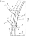
- rotor clip 114 may be installable or installed into scallop 281 by sliding rotor clip 114 into scallop 281 from the axial side of slot 257 (See momentarily FIG. 3 , which, as shown, similarly depicts rotor clip 314 being positioned to slide into scallop 381 from the axial side of slot 357).
- a single tab or multiple tabs (e.g., two tabs) of tab engagement portion 271 and tab engagement portion 272 may be bent circumferentially outward to keep rotor clip 114 from moving either circumferentially or radially on rotor disk 102.
- rotor clip 114 may be removed by either displacing rotor clip 114, bending rotor clip 114, or re-bending the tab/s of tab engagement portion 271 and tab engagement portion 272 and removing rotor clip 114. In various embodiments, in the event that rotor clip 114 becomes damaged, rotor clip 114 may be easily removed and reinstalled.
- Rotor clip 314 is similar in design to rotor clip 114, however, tab 371 and tab 372 include only a single tab.
- Rotor clip 314 may be held in place on rotor disk 102 utilizing an undercut engagement portion 370 of slot 357, defined by rotor lugs 350 and 351, and an undercut coupling portion 379 of rotor clip 314.
- Undercut engagement portion 370 may be, for example, defined by the bearing faces 383 of rotor lug 350 and rotor lug 351, and a scallop 381 portion connecting the bearing faces 383 of the adjacent lugs.
- Undercut coupling portion 379 may be, for example, the portion of rotor clip 314 designed to be affixed to undercut 370.
- Undercut coupling portion 379 may include a first bump 391 on one end and a second bump 392 on an opposite end.
- bump 391 may be in the shape of a partially circular end and bump 392 may be in the shape of a partially circular end.
- the shapes of bumps 391 and 392 may be rounded, a half-circle, or any other shape and dimensions that are complementary to the shape and dimensions of the bearing face 383 portions that define a first undercut 370a and a second undercut 370b.
- bump 391 and bump 392 clip into first undercut 370a of undercut engagement portion 370 and second undercut 370b of undercut engagement portion 370.
- Undercut engagement portion 370 is located radially inward of circumferentially protruding bearing face portions 383a and 383b.
- the shape of the bearing face 383 portions defining the first undercut 370a and the second undercut 370b may be curved, concave or any other shape where the defining surface of bearing face 383 is misaligned in a circumferential direction with bearing face portions 383a and 383b.
- undercut engagement portion 370 may be circumferentially inward of the bearing face portions 383a and 383b of rotor lug 350 and rotor lug 351, respectively, to a degree that allows the combination of undercut coupling portion 379 of rotor clip 314 and undercut engagement portion 370 to provide mechanical retention ability to rotor clip 314.
- rotor clip 314 may engage with rotor disk 102 utilizing first bump 391 and second bump 392 located on either side of rotor clip 314. In various embodiments, rotor clip 314 may be inserted in to slot 357 from a radially outward to inward direction. In various embodiments, first bump 391 and second bump 392 may fit into undercut engagement portion 370 on rotor disk 102. In various embodiments, rotor clip 314 may be held circumferentially onto rotor disk 102 by the use of tab engagement portion 371 and tab engagement portion 372 located on either side of rotor clip 314. In various embodiments, tab engagement portion 371 and tab engagement portion 372 may be clippable to rotor lug 350 and 351.
- Tab engagement portion 371 and tab engagement portion 372 may, for example, bend circumferentially outward in opposite directions to allow rotor clip 314 to lock in place on rotor lug 350 and rotor lug 351, respectively.
- rotor clip 314 may be placed radially outward of scallop 381 that defines a bottom portion and/or engagement portion 370 of slot 357.
- slot 357 is located between rotor lug 350 and rotor lug 351 and designed to encompass rotor clip 314.
- slot 357 may be designed such that bump 391 and bump 392 fit directly into first undercut 370a and second undercut 370b of undercut engagement portion 370 of slot 357.
- a first end of slot 357 may be defined by a side-wall, e.g. , bearing face 383a, of rotor lug 350 and a second end of slot 357 may be defined by a side-wall, e.g., bearing face 383b, of rotor lug 351, as depicted in, for example, FIG. 3
- method 400 may include aligning a rotor clip 114, 314 to a slot 257, 357.
- method 400 may include engaging a first bump and a second bump of the rotor clip 114, 314 with undercut engagement portion 270, 370 of the slot 257, 357 of rotor disk 102.
- method 400 may include snapping the rotor clip 114, 314 into the slot 257, 357 to position and retain an undercut coupling portion 279,379 of rotor clip 114, 314 radially within an undercut engagement portion 270, 370 of slot 257, 357.
Landscapes
- Engineering & Computer Science (AREA)
- General Engineering & Computer Science (AREA)
- Mechanical Engineering (AREA)
- Braking Arrangements (AREA)
Claims (15)
- Ensemble disque de frein comprenant un disque de rotor (102) et une pince de rotor (114), ladite pince de rotor (114) comprenant :une première partie de mise en prise de languette (271),une partie de couplage de contre-dépouille (279) couplée à ladite première partie de mise en prise de languette (271) ; etune seconde partie de mise en prise de languette (272) couplée à ladite partie de couplage de contre-dépouille (279), dans lequel ladite partie de couplage de contre-dépouille (279) a une première bosse (291) et une seconde bosse (292), etcaractérisé en ce que ladite première partie de mise en prise de languette (271) comprend une première ou plusieurs premières languettes et ladite seconde partie de mise en prise de languette (272) comprend une seconde ou plusieurs secondes languettes et dans laquelle ladite première languette de ladite première partie de mise en prise de languette et ladite seconde languette de ladite seconde partie de mise en prise de languette sont conçues pour être courbées circonférentiellement vers l'extérieur pour mettre en prise ladite première bosse de ladite pince de rotor (114) avec une première contre-dépouille de la fente et ladite seconde bosse de ladite pince de rotor (114) avec une seconde contre-dépouille de ladite fente dudit disque de rotor (102) ; etdans lequel ladite première languette de ladite première partie de mise en prise de languette de ladite pince de rotor (114) est conçue pour être encliquetée sur le disque de rotor et dans lequel ladite seconde languette de ladite seconde partie de mise en prise est conçue pour être encliquetée sur le disque de rotor.
- Ensemble disque de frein selon la revendication 1, dans lequel ladite partie de couplage de contre-dépouille (279) est utilisée pour mettre en prise ladite pince de rotor (114) dans ladite fente (257) dudit disque de rotor (102), ou
dans lequel ladite première bosse est située à une première extrémité de ladite partie de couplage de contre-dépouille (279) et ladite seconde bosse est située à une seconde extrémité de ladite partie de couplage de contre-dépouille. - Ensemble disque de frein selon la revendication 1, dans lequel ladite première bosse est partiellement circulaire et ladite seconde bosse est partiellement circulaire.
- Ensemble disque de frein selon la revendication 1, 2 ou 3, dans lequel ladite pince de rotor (114) est maintenue circonférentiellement sur un disque de rotor en utilisant ladite première partie de mise en prise de languette et ladite seconde partie de mise en prise de languette.
- Ensemble disque de frein selon l'une quelconque des revendications 1 à 4, dans lequel ladite première partie de mise en prise de languette est située d'un premier côté de ladite pince de rotor (114) et ladite seconde partie de mise en prise de languette est située d'un second côté de ladite pince de rotor (114).
- Ensemble disque de frein selon l'une quelconque des revendications 1 à 4, dans lequel ladite première partie de mise en prise de languette comporte un ensemble de deux languettes et ladite seconde partie de mise en prise de languette comporte un ensemble de deux languettes.
- Ensemble disque de frein selon l'une quelconque des revendications 1 à 4, dans lequel ladite première partie de mise en prise de languette comporte une languette unique et ladite seconde partie de mise en prise de languette comporte une languette unique.
- Ensemble disque de frein selon l'une quelconque des revendications 1 à 7, dans lequel ladite pince de rotor est conçue pour être installée dans ladite fente d'un disque de rotor (114) en encliquetant ledit premier ensemble de languettes de ladite première partie de mise en prise de languette sur un premier ergot de rotor (150) dudit disque de rotor et ledit second ensemble de languettes de ladite seconde partie de mise en prise de languette sur un second ergot de rotor (151) dudit disque de rotor, ou
dans lequel ladite pince de rotor (114) peut être installée sur un feston définissant une partie inférieure de ladite fente d'un disque de rotor (114) en faisant coulisser ladite pince de rotor sur ledit feston, ou
dans lequel ladite pince de rotor (114) peut être installée dans ladite fente d'un disque de rotor en mettant en prise ladite partie de couplage de contre-dépouille (279) et en encliquetant ledit premier ensemble de languettes de ladite première partie de mise en prise de languette sur un premier ergot de rotor (150) dudit disque de rotor (114) et un second ensemble de languettes de ladite seconde partie de mise en prise de languette sur un second ergot de rotor (151) dudit disque de rotor (114). - Ensemble disque de frein selon la revendication 1, ledit disque de rotor (102) comprenant :un premier ergot de rotor (150) ; etun second ergot de rotor (151) espacé circonférentiellement dudit premier ergot de rotor (150) et définissant ladite fente (257) entre eux, dans lequel ladite fente est située sur une partie radialement extérieure dudit disque de rotor (102) et ladite fente (257) a une partie de mise en prise de contre-dépouille définie par ledit premier ergot de rotor (150) et ledit second ergot de rotor (151).
- Ensemble disque de frein selon la revendication 9, dans lequel ladite partie de mise en prise de contre-dépouille (270) est positionnée circonférentiellement sur ledit disque de rotor pour mettre en prise ladite pince de rotor.
- Ensemble disque de frein selon la revendication 9, dans lequel ladite partie de mise en prise de contre-dépouille (270) comporte une première contre-dépouille (270a) et une seconde contre-dépouille (270b), et
dans lequel ladite première contre-dépouille (270a) est radialement vers l'intérieur et circonférentiellement désalignée avec une partie de face d'appui circonférentiellement saillante dudit premier ergot de rotor (150) et ladite seconde contre-dépouille (270b) est radialement vers l'intérieur et circonférentiellement désalignée avec une partie de face d'appui circonférentiellement saillante dudit second ergot de rotor (151), et
dans lequel ladite partie de face d'appui circonférentiellement saillante dudit premier ergot de rotor (150) et ladite partie de face d'appui circonférentiellement saillante dudit second ergot de rotor (151) ont chacune une partie de forme concave définissant respectivement ladite première contre-dépouille (270a) et ladite seconde contre-dépouille (270b). - Ensemble disque de frein selon la revendication 9, dans lequel ladite partie de mise en prise de contre-dépouille (270) est définie par un premier bord partiellement circulaire d'un premier côté de ladite fente et un second bord partiellement circulaire d'un second côté de ladite fente (257).
- Ensemble disque de frein selon la revendication 9, dans lequel ladite partie de mise en prise de contre-dépouille (270) est définie par une face d'appui dudit premier ergot de rotor (150) et définie par une face d'appui dudit second ergot de rotor (151).
- Procédé de formation d'un ensemble disque de frein selon l'une quelconque des revendications 1 à 13, comprenant l'insertion d'une pince de rotor dans une fente d'un disque de rotor, comprenant :l'alignement de ladite pince de rotor (114) sur ladite fente (257) située sur une partie radialement extérieure dudit disque de rotor (114) ; etcaractérisé en ce que ladite première partie de mise en prise de languette (271) comprend une première ou plusieurs premières languettes et ladite seconde partie de mise en prise de languette (272) comprend une seconde ou plusieurs secondes languettes etledit procédé comprend en outre le pliage de ladite première languette de ladite première partie de mise en prise de languette et de ladite seconde languette de ladite seconde partie de mise en prise de languette circonférentiellement vers l'extérieur etla mise en prise d'une première bosse de ladite pince de rotor (114) avec une première contre-dépouille de la fente et une seconde bosse de ladite pince de rotor (114) avec une seconde contre-dépouille de ladite fente dudit disque de rotor (102) ; etl'encliquetage de ladite première languette de ladite première partie de mise en prise de languette (114) sur un premier ergot de rotor du disque de rotor et l'encliquetage d'une seconde languette de ladite seconde partie de mise en prise sur un second ergot de rotor du disque de rotor pour contribuer au positionnement et à la retenue de ladite partie de couplage de contre-dépouille de ladite pince de rotor (114) radialement à l'intérieur de ladite partie de mise en prise de contre-dépouille de ladite fente (257).
- Procédé selon la revendication 14, dans lequel ladite partie de mise en prise de contre-dépouille a un premier bord circulaire et un second bord circulaire positionnés pour recevoir ladite partie de couplage de contre-dépouille (279).
Applications Claiming Priority (1)
| Application Number | Priority Date | Filing Date | Title |
|---|---|---|---|
| US15/673,591 US10436265B2 (en) | 2017-08-10 | 2017-08-10 | Rivet-less rotor clip design |
Publications (2)
| Publication Number | Publication Date |
|---|---|
| EP3441638A1 EP3441638A1 (fr) | 2019-02-13 |
| EP3441638B1 true EP3441638B1 (fr) | 2020-08-05 |
Family
ID=63209269
Family Applications (1)
| Application Number | Title | Priority Date | Filing Date |
|---|---|---|---|
| EP18188460.2A Active EP3441638B1 (fr) | 2017-08-10 | 2018-08-10 | Conception de pince de rotor sans rivet |
Country Status (2)
| Country | Link |
|---|---|
| US (1) | US10436265B2 (fr) |
| EP (1) | EP3441638B1 (fr) |
Families Citing this family (7)
| Publication number | Priority date | Publication date | Assignee | Title |
|---|---|---|---|---|
| US11644070B2 (en) | 2020-01-22 | 2023-05-09 | Honeywell International Inc. | Brake disc insert with retainer |
| CN111173864A (zh) * | 2020-02-12 | 2020-05-19 | 烟台胜地汽车零部件制造有限公司 | 一种复合制动盘连接组件及复合制动盘 |
| US11346416B2 (en) * | 2020-04-23 | 2022-05-31 | Honeywell International Inc. | Brake disc insert with bridge member |
| US11560930B2 (en) | 2020-10-23 | 2023-01-24 | Honeywell International Inc. | Brake disc insert with retainer |
| EP4155570B1 (fr) * | 2021-09-24 | 2024-04-17 | Goodrich Corporation | Pince de rotor pour ensemble frein |
| US11913510B2 (en) * | 2021-09-27 | 2024-02-27 | Goodrich Corporation | Rotor clip apparatus and systems |
| EP4290092A1 (fr) * | 2022-06-08 | 2023-12-13 | Goodrich Corporation | Pince de rotor pour un ensemble frein |
Family Cites Families (13)
| Publication number | Priority date | Publication date | Assignee | Title |
|---|---|---|---|---|
| US3250349A (en) * | 1964-03-20 | 1966-05-10 | American Brake Shoe Co | Disc brake |
| US4007814A (en) * | 1976-02-05 | 1977-02-15 | Goodyear Aerospace Corporation | Carbon brake disk with cast keyslot reinforcement members |
| US4465165A (en) * | 1983-01-28 | 1984-08-14 | The B. F. Goodrich Company | Brake apparatus |
| US4557356A (en) * | 1984-04-30 | 1985-12-10 | Goodyear Aerospace Corporation | Brake disk and keyslot reinforcements therefor |
| US4747473A (en) * | 1986-06-19 | 1988-05-31 | The B. F. Goodrich Company | Segmented friction brake or clutch disc assembly |
| US4863001A (en) | 1987-02-18 | 1989-09-05 | The Bf Goodrich Company | Brake apparatus |
| US4784246A (en) * | 1987-02-18 | 1988-11-15 | The B. F. Goodrich Company | Brake apparatus |
| US7442443B2 (en) * | 2005-05-31 | 2008-10-28 | Goodrich Corporation | Chromium-nickel stainless steel alloy article having oxide coating formed from the base metal suitable for brake apparatus |
| US20070193836A1 (en) | 2006-02-23 | 2007-08-23 | Walker Terence B | Method and brake disc with composite insert member |
| US7766133B2 (en) | 2007-06-04 | 2010-08-03 | Honeywell International, Inc. | Insert and retainer for securing same to an aircraft brake disk |
| US20160279710A1 (en) * | 2015-03-25 | 2016-09-29 | Goodrich Corporation | Aircraft brake rotor clip repair methods |
| US9897153B2 (en) | 2015-11-11 | 2018-02-20 | Goodrich Corporation | Low radial profile brake disk insert retainer |
| US10221905B2 (en) * | 2016-11-09 | 2019-03-05 | Goodrich Corporation | Bridged clip retainer for brake system |
-
2017
- 2017-08-10 US US15/673,591 patent/US10436265B2/en active Active
-
2018
- 2018-08-10 EP EP18188460.2A patent/EP3441638B1/fr active Active
Non-Patent Citations (1)
| Title |
|---|
| None * |
Also Published As
| Publication number | Publication date |
|---|---|
| US20190048949A1 (en) | 2019-02-14 |
| US10436265B2 (en) | 2019-10-08 |
| EP3441638A1 (fr) | 2019-02-13 |
Similar Documents
| Publication | Publication Date | Title |
|---|---|---|
| EP3441638B1 (fr) | Conception de pince de rotor sans rivet | |
| CN101529052B (zh) | 涡轮叶片组件 | |
| US9309782B2 (en) | Flat bottom damper pin for turbine blades | |
| JP5356083B2 (ja) | 軸流圧縮機ブレード保持 | |
| KR101711374B1 (ko) | 디스크에 관하여 블레이드를 로크하는 축방향 유지 링이 장착된 터빈 휠 | |
| CN101482136B (zh) | 轴向保持系统 | |
| US8459953B2 (en) | Seal plate and bucket retention pin assembly | |
| EP3327308B1 (fr) | Système de freinage avec dispositif de retenue d'attache à pont | |
| EP2025965A1 (fr) | Ensemble de disque de frein | |
| EP3168491B1 (fr) | Dispositif de fixation unique de retenue de plaquette de disque de frein | |
| CN105781625B (zh) | 用于安装涡轮动叶的卡具和方法 | |
| JP2002530580A (ja) | ディスクへのタービンブレード保持装置 | |
| US5622476A (en) | Axial fixing arrangement for rotor blades of a turbomachine | |
| EP3168492B1 (fr) | Retenue de plaquette de disque de frein à faible profil radial | |
| EP2439378A2 (fr) | Prévention de rotation de fil à freiner d'aube de turbine | |
| EP2562357B1 (fr) | Ensemble insert de tuteurage remplaçable et procédé associé | |
| US8128374B2 (en) | Securing element for fastening rotor blades | |
| US20060024167A1 (en) | Rotor disk for a turbomachine | |
| EP2299059A2 (fr) | Ensemble de pale profilée | |
| JP7209870B2 (ja) | リングファスナー | |
| CN112313396B (zh) | 用于拆卸叶片轮的保持系统 | |
| CN111619793A (zh) | 设有隔热罩的飞行器轮子 | |
| CN112534119A (zh) | 具有设置在两个转子盘之间的转子构件的转子 | |
| EP3680501B1 (fr) | Ensembles de bague de retenue | |
| CN104271893A (zh) | 限制径向移动的保持夹、涡轮机框架和方法 |
Legal Events
| Date | Code | Title | Description |
|---|---|---|---|
| PUAI | Public reference made under article 153(3) epc to a published international application that has entered the european phase |
Free format text: ORIGINAL CODE: 0009012 |
|
| STAA | Information on the status of an ep patent application or granted ep patent |
Free format text: STATUS: THE APPLICATION HAS BEEN PUBLISHED |
|
| AK | Designated contracting states |
Kind code of ref document: A1 Designated state(s): AL AT BE BG CH CY CZ DE DK EE ES FI FR GB GR HR HU IE IS IT LI LT LU LV MC MK MT NL NO PL PT RO RS SE SI SK SM TR |
|
| AX | Request for extension of the european patent |
Extension state: BA ME |
|
| STAA | Information on the status of an ep patent application or granted ep patent |
Free format text: STATUS: REQUEST FOR EXAMINATION WAS MADE |
|
| 17P | Request for examination filed |
Effective date: 20190809 |
|
| RBV | Designated contracting states (corrected) |
Designated state(s): AL AT BE BG CH CY CZ DE DK EE ES FI FR GB GR HR HU IE IS IT LI LT LU LV MC MK MT NL NO PL PT RO RS SE SI SK SM TR |
|
| GRAP | Despatch of communication of intention to grant a patent |
Free format text: ORIGINAL CODE: EPIDOSNIGR1 |
|
| STAA | Information on the status of an ep patent application or granted ep patent |
Free format text: STATUS: GRANT OF PATENT IS INTENDED |
|
| INTG | Intention to grant announced |
Effective date: 20200312 |
|
| GRAS | Grant fee paid |
Free format text: ORIGINAL CODE: EPIDOSNIGR3 |
|
| GRAA | (expected) grant |
Free format text: ORIGINAL CODE: 0009210 |
|
| STAA | Information on the status of an ep patent application or granted ep patent |
Free format text: STATUS: THE PATENT HAS BEEN GRANTED |
|
| AK | Designated contracting states |
Kind code of ref document: B1 Designated state(s): AL AT BE BG CH CY CZ DE DK EE ES FI FR GB GR HR HU IE IS IT LI LT LU LV MC MK MT NL NO PL PT RO RS SE SI SK SM TR |
|
| REG | Reference to a national code |
Ref country code: GB Ref legal event code: FG4D |
|
| REG | Reference to a national code |
Ref country code: CH Ref legal event code: EP |
|
| REG | Reference to a national code |
Ref country code: AT Ref legal event code: REF Ref document number: 1299127 Country of ref document: AT Kind code of ref document: T Effective date: 20200815 |
|
| REG | Reference to a national code |
Ref country code: DE Ref legal event code: R096 Ref document number: 602018006612 Country of ref document: DE |
|
| REG | Reference to a national code |
Ref country code: IE Ref legal event code: FG4D |
|
| REG | Reference to a national code |
Ref country code: LT Ref legal event code: MG4D |
|
| REG | Reference to a national code |
Ref country code: NL Ref legal event code: MP Effective date: 20200805 |
|
| REG | Reference to a national code |
Ref country code: AT Ref legal event code: MK05 Ref document number: 1299127 Country of ref document: AT Kind code of ref document: T Effective date: 20200805 |
|
| PG25 | Lapsed in a contracting state [announced via postgrant information from national office to epo] |
Ref country code: ES Free format text: LAPSE BECAUSE OF FAILURE TO SUBMIT A TRANSLATION OF THE DESCRIPTION OR TO PAY THE FEE WITHIN THE PRESCRIBED TIME-LIMIT Effective date: 20200805 Ref country code: PT Free format text: LAPSE BECAUSE OF FAILURE TO SUBMIT A TRANSLATION OF THE DESCRIPTION OR TO PAY THE FEE WITHIN THE PRESCRIBED TIME-LIMIT Effective date: 20201207 Ref country code: GR Free format text: LAPSE BECAUSE OF FAILURE TO SUBMIT A TRANSLATION OF THE DESCRIPTION OR TO PAY THE FEE WITHIN THE PRESCRIBED TIME-LIMIT Effective date: 20201106 Ref country code: NO Free format text: LAPSE BECAUSE OF FAILURE TO SUBMIT A TRANSLATION OF THE DESCRIPTION OR TO PAY THE FEE WITHIN THE PRESCRIBED TIME-LIMIT Effective date: 20201105 Ref country code: AT Free format text: LAPSE BECAUSE OF FAILURE TO SUBMIT A TRANSLATION OF THE DESCRIPTION OR TO PAY THE FEE WITHIN THE PRESCRIBED TIME-LIMIT Effective date: 20200805 Ref country code: SE Free format text: LAPSE BECAUSE OF FAILURE TO SUBMIT A TRANSLATION OF THE DESCRIPTION OR TO PAY THE FEE WITHIN THE PRESCRIBED TIME-LIMIT Effective date: 20200805 Ref country code: FI Free format text: LAPSE BECAUSE OF FAILURE TO SUBMIT A TRANSLATION OF THE DESCRIPTION OR TO PAY THE FEE WITHIN THE PRESCRIBED TIME-LIMIT Effective date: 20200805 Ref country code: HR Free format text: LAPSE BECAUSE OF FAILURE TO SUBMIT A TRANSLATION OF THE DESCRIPTION OR TO PAY THE FEE WITHIN THE PRESCRIBED TIME-LIMIT Effective date: 20200805 Ref country code: BG Free format text: LAPSE BECAUSE OF FAILURE TO SUBMIT A TRANSLATION OF THE DESCRIPTION OR TO PAY THE FEE WITHIN THE PRESCRIBED TIME-LIMIT Effective date: 20201105 Ref country code: LT Free format text: LAPSE BECAUSE OF FAILURE TO SUBMIT A TRANSLATION OF THE DESCRIPTION OR TO PAY THE FEE WITHIN THE PRESCRIBED TIME-LIMIT Effective date: 20200805 |
|
| PG25 | Lapsed in a contracting state [announced via postgrant information from national office to epo] |
Ref country code: LV Free format text: LAPSE BECAUSE OF FAILURE TO SUBMIT A TRANSLATION OF THE DESCRIPTION OR TO PAY THE FEE WITHIN THE PRESCRIBED TIME-LIMIT Effective date: 20200805 Ref country code: NL Free format text: LAPSE BECAUSE OF FAILURE TO SUBMIT A TRANSLATION OF THE DESCRIPTION OR TO PAY THE FEE WITHIN THE PRESCRIBED TIME-LIMIT Effective date: 20200805 Ref country code: PL Free format text: LAPSE BECAUSE OF FAILURE TO SUBMIT A TRANSLATION OF THE DESCRIPTION OR TO PAY THE FEE WITHIN THE PRESCRIBED TIME-LIMIT Effective date: 20200805 Ref country code: RS Free format text: LAPSE BECAUSE OF FAILURE TO SUBMIT A TRANSLATION OF THE DESCRIPTION OR TO PAY THE FEE WITHIN THE PRESCRIBED TIME-LIMIT Effective date: 20200805 Ref country code: IS Free format text: LAPSE BECAUSE OF FAILURE TO SUBMIT A TRANSLATION OF THE DESCRIPTION OR TO PAY THE FEE WITHIN THE PRESCRIBED TIME-LIMIT Effective date: 20201205 |
|
| REG | Reference to a national code |
Ref country code: DE Ref legal event code: R119 Ref document number: 602018006612 Country of ref document: DE |
|
| PG25 | Lapsed in a contracting state [announced via postgrant information from national office to epo] |
Ref country code: RO Free format text: LAPSE BECAUSE OF FAILURE TO SUBMIT A TRANSLATION OF THE DESCRIPTION OR TO PAY THE FEE WITHIN THE PRESCRIBED TIME-LIMIT Effective date: 20200805 Ref country code: CZ Free format text: LAPSE BECAUSE OF FAILURE TO SUBMIT A TRANSLATION OF THE DESCRIPTION OR TO PAY THE FEE WITHIN THE PRESCRIBED TIME-LIMIT Effective date: 20200805 Ref country code: DK Free format text: LAPSE BECAUSE OF FAILURE TO SUBMIT A TRANSLATION OF THE DESCRIPTION OR TO PAY THE FEE WITHIN THE PRESCRIBED TIME-LIMIT Effective date: 20200805 Ref country code: EE Free format text: LAPSE BECAUSE OF FAILURE TO SUBMIT A TRANSLATION OF THE DESCRIPTION OR TO PAY THE FEE WITHIN THE PRESCRIBED TIME-LIMIT Effective date: 20200805 Ref country code: LU Free format text: LAPSE BECAUSE OF NON-PAYMENT OF DUE FEES Effective date: 20200810 Ref country code: SM Free format text: LAPSE BECAUSE OF FAILURE TO SUBMIT A TRANSLATION OF THE DESCRIPTION OR TO PAY THE FEE WITHIN THE PRESCRIBED TIME-LIMIT Effective date: 20200805 |
|
| REG | Reference to a national code |
Ref country code: BE Ref legal event code: MM Effective date: 20200831 |
|
| PG25 | Lapsed in a contracting state [announced via postgrant information from national office to epo] |
Ref country code: AL Free format text: LAPSE BECAUSE OF FAILURE TO SUBMIT A TRANSLATION OF THE DESCRIPTION OR TO PAY THE FEE WITHIN THE PRESCRIBED TIME-LIMIT Effective date: 20200805 Ref country code: MC Free format text: LAPSE BECAUSE OF FAILURE TO SUBMIT A TRANSLATION OF THE DESCRIPTION OR TO PAY THE FEE WITHIN THE PRESCRIBED TIME-LIMIT Effective date: 20200805 |
|
| PLBE | No opposition filed within time limit |
Free format text: ORIGINAL CODE: 0009261 |
|
| STAA | Information on the status of an ep patent application or granted ep patent |
Free format text: STATUS: NO OPPOSITION FILED WITHIN TIME LIMIT |
|
| PG25 | Lapsed in a contracting state [announced via postgrant information from national office to epo] |
Ref country code: SK Free format text: LAPSE BECAUSE OF FAILURE TO SUBMIT A TRANSLATION OF THE DESCRIPTION OR TO PAY THE FEE WITHIN THE PRESCRIBED TIME-LIMIT Effective date: 20200805 |
|
| 26N | No opposition filed |
Effective date: 20210507 |
|
| PG25 | Lapsed in a contracting state [announced via postgrant information from national office to epo] |
Ref country code: IT Free format text: LAPSE BECAUSE OF FAILURE TO SUBMIT A TRANSLATION OF THE DESCRIPTION OR TO PAY THE FEE WITHIN THE PRESCRIBED TIME-LIMIT Effective date: 20200805 Ref country code: DE Free format text: LAPSE BECAUSE OF NON-PAYMENT OF DUE FEES Effective date: 20210302 |
|
| PG25 | Lapsed in a contracting state [announced via postgrant information from national office to epo] |
Ref country code: BE Free format text: LAPSE BECAUSE OF NON-PAYMENT OF DUE FEES Effective date: 20200831 Ref country code: SI Free format text: LAPSE BECAUSE OF FAILURE TO SUBMIT A TRANSLATION OF THE DESCRIPTION OR TO PAY THE FEE WITHIN THE PRESCRIBED TIME-LIMIT Effective date: 20200805 Ref country code: IE Free format text: LAPSE BECAUSE OF NON-PAYMENT OF DUE FEES Effective date: 20200810 |
|
| REG | Reference to a national code |
Ref country code: CH Ref legal event code: PL |
|
| PG25 | Lapsed in a contracting state [announced via postgrant information from national office to epo] |
Ref country code: LI Free format text: LAPSE BECAUSE OF NON-PAYMENT OF DUE FEES Effective date: 20210831 Ref country code: CH Free format text: LAPSE BECAUSE OF NON-PAYMENT OF DUE FEES Effective date: 20210831 |
|
| PG25 | Lapsed in a contracting state [announced via postgrant information from national office to epo] |
Ref country code: TR Free format text: LAPSE BECAUSE OF FAILURE TO SUBMIT A TRANSLATION OF THE DESCRIPTION OR TO PAY THE FEE WITHIN THE PRESCRIBED TIME-LIMIT Effective date: 20200805 Ref country code: MT Free format text: LAPSE BECAUSE OF FAILURE TO SUBMIT A TRANSLATION OF THE DESCRIPTION OR TO PAY THE FEE WITHIN THE PRESCRIBED TIME-LIMIT Effective date: 20200805 Ref country code: CY Free format text: LAPSE BECAUSE OF FAILURE TO SUBMIT A TRANSLATION OF THE DESCRIPTION OR TO PAY THE FEE WITHIN THE PRESCRIBED TIME-LIMIT Effective date: 20200805 |
|
| PG25 | Lapsed in a contracting state [announced via postgrant information from national office to epo] |
Ref country code: MK Free format text: LAPSE BECAUSE OF FAILURE TO SUBMIT A TRANSLATION OF THE DESCRIPTION OR TO PAY THE FEE WITHIN THE PRESCRIBED TIME-LIMIT Effective date: 20200805 |
|
| P01 | Opt-out of the competence of the unified patent court (upc) registered |
Effective date: 20230521 |
|
| PGFP | Annual fee paid to national office [announced via postgrant information from national office to epo] |
Ref country code: GB Payment date: 20230720 Year of fee payment: 6 |
|
| PGFP | Annual fee paid to national office [announced via postgrant information from national office to epo] |
Ref country code: FR Payment date: 20230720 Year of fee payment: 6 |