EP3441576A1 - Turbine fan system and method - Google Patents
Turbine fan system and method Download PDFInfo
- Publication number
- EP3441576A1 EP3441576A1 EP18188456.0A EP18188456A EP3441576A1 EP 3441576 A1 EP3441576 A1 EP 3441576A1 EP 18188456 A EP18188456 A EP 18188456A EP 3441576 A1 EP3441576 A1 EP 3441576A1
- Authority
- EP
- European Patent Office
- Prior art keywords
- shaft
- fan
- dry film
- film lubricant
- diameter surface
- Prior art date
- Legal status (The legal status is an assumption and is not a legal conclusion. Google has not performed a legal analysis and makes no representation as to the accuracy of the status listed.)
- Granted
Links
Images




Classifications
-
- F—MECHANICAL ENGINEERING; LIGHTING; HEATING; WEAPONS; BLASTING
- F02—COMBUSTION ENGINES; HOT-GAS OR COMBUSTION-PRODUCT ENGINE PLANTS
- F02K—JET-PROPULSION PLANTS
- F02K3/00—Plants including a gas turbine driving a compressor or a ducted fan
- F02K3/02—Plants including a gas turbine driving a compressor or a ducted fan in which part of the working fluid by-passes the turbine and combustion chamber
- F02K3/04—Plants including a gas turbine driving a compressor or a ducted fan in which part of the working fluid by-passes the turbine and combustion chamber the plant including ducted fans, i.e. fans with high volume, low pressure outputs, for augmenting the jet thrust, e.g. of double-flow type
- F02K3/06—Plants including a gas turbine driving a compressor or a ducted fan in which part of the working fluid by-passes the turbine and combustion chamber the plant including ducted fans, i.e. fans with high volume, low pressure outputs, for augmenting the jet thrust, e.g. of double-flow type with front fan
-
- F—MECHANICAL ENGINEERING; LIGHTING; HEATING; WEAPONS; BLASTING
- F01—MACHINES OR ENGINES IN GENERAL; ENGINE PLANTS IN GENERAL; STEAM ENGINES
- F01D—NON-POSITIVE DISPLACEMENT MACHINES OR ENGINES, e.g. STEAM TURBINES
- F01D25/00—Component parts, details, or accessories, not provided for in, or of interest apart from, other groups
- F01D25/007—Preventing corrosion
-
- F—MECHANICAL ENGINEERING; LIGHTING; HEATING; WEAPONS; BLASTING
- F04—POSITIVE - DISPLACEMENT MACHINES FOR LIQUIDS; PUMPS FOR LIQUIDS OR ELASTIC FLUIDS
- F04D—NON-POSITIVE-DISPLACEMENT PUMPS
- F04D29/00—Details, component parts, or accessories
- F04D29/05—Shafts or bearings, or assemblies thereof, specially adapted for elastic fluid pumps
- F04D29/053—Shafts
-
- F—MECHANICAL ENGINEERING; LIGHTING; HEATING; WEAPONS; BLASTING
- F02—COMBUSTION ENGINES; HOT-GAS OR COMBUSTION-PRODUCT ENGINE PLANTS
- F02C—GAS-TURBINE PLANTS; AIR INTAKES FOR JET-PROPULSION PLANTS; CONTROLLING FUEL SUPPLY IN AIR-BREATHING JET-PROPULSION PLANTS
- F02C7/00—Features, components parts, details or accessories, not provided for in, or of interest apart form groups F02C1/00 - F02C6/00; Air intakes for jet-propulsion plants
- F02C7/06—Arrangements of bearings; Lubricating
-
- F—MECHANICAL ENGINEERING; LIGHTING; HEATING; WEAPONS; BLASTING
- F04—POSITIVE - DISPLACEMENT MACHINES FOR LIQUIDS; PUMPS FOR LIQUIDS OR ELASTIC FLUIDS
- F04D—NON-POSITIVE-DISPLACEMENT PUMPS
- F04D29/00—Details, component parts, or accessories
- F04D29/02—Selection of particular materials
- F04D29/023—Selection of particular materials especially adapted for elastic fluid pumps
-
- F—MECHANICAL ENGINEERING; LIGHTING; HEATING; WEAPONS; BLASTING
- F04—POSITIVE - DISPLACEMENT MACHINES FOR LIQUIDS; PUMPS FOR LIQUIDS OR ELASTIC FLUIDS
- F04D—NON-POSITIVE-DISPLACEMENT PUMPS
- F04D29/00—Details, component parts, or accessories
- F04D29/06—Lubrication
- F04D29/063—Lubrication specially adapted for elastic fluid pumps
-
- F—MECHANICAL ENGINEERING; LIGHTING; HEATING; WEAPONS; BLASTING
- F05—INDEXING SCHEMES RELATING TO ENGINES OR PUMPS IN VARIOUS SUBCLASSES OF CLASSES F01-F04
- F05D—INDEXING SCHEME FOR ASPECTS RELATING TO NON-POSITIVE-DISPLACEMENT MACHINES OR ENGINES, GAS-TURBINES OR JET-PROPULSION PLANTS
- F05D2220/00—Application
- F05D2220/30—Application in turbines
- F05D2220/36—Application in turbines specially adapted for the fan of turbofan engines
-
- F—MECHANICAL ENGINEERING; LIGHTING; HEATING; WEAPONS; BLASTING
- F05—INDEXING SCHEMES RELATING TO ENGINES OR PUMPS IN VARIOUS SUBCLASSES OF CLASSES F01-F04
- F05D—INDEXING SCHEME FOR ASPECTS RELATING TO NON-POSITIVE-DISPLACEMENT MACHINES OR ENGINES, GAS-TURBINES OR JET-PROPULSION PLANTS
- F05D2230/00—Manufacture
- F05D2230/90—Coating; Surface treatment
-
- F—MECHANICAL ENGINEERING; LIGHTING; HEATING; WEAPONS; BLASTING
- F05—INDEXING SCHEMES RELATING TO ENGINES OR PUMPS IN VARIOUS SUBCLASSES OF CLASSES F01-F04
- F05D—INDEXING SCHEME FOR ASPECTS RELATING TO NON-POSITIVE-DISPLACEMENT MACHINES OR ENGINES, GAS-TURBINES OR JET-PROPULSION PLANTS
- F05D2240/00—Components
- F05D2240/60—Shafts
- F05D2240/61—Hollow
-
- F—MECHANICAL ENGINEERING; LIGHTING; HEATING; WEAPONS; BLASTING
- F05—INDEXING SCHEMES RELATING TO ENGINES OR PUMPS IN VARIOUS SUBCLASSES OF CLASSES F01-F04
- F05D—INDEXING SCHEME FOR ASPECTS RELATING TO NON-POSITIVE-DISPLACEMENT MACHINES OR ENGINES, GAS-TURBINES OR JET-PROPULSION PLANTS
- F05D2260/00—Function
- F05D2260/60—Fluid transfer
- F05D2260/609—Deoiling or demisting
-
- F—MECHANICAL ENGINEERING; LIGHTING; HEATING; WEAPONS; BLASTING
- F05—INDEXING SCHEMES RELATING TO ENGINES OR PUMPS IN VARIOUS SUBCLASSES OF CLASSES F01-F04
- F05D—INDEXING SCHEME FOR ASPECTS RELATING TO NON-POSITIVE-DISPLACEMENT MACHINES OR ENGINES, GAS-TURBINES OR JET-PROPULSION PLANTS
- F05D2260/00—Function
- F05D2260/98—Lubrication
-
- F—MECHANICAL ENGINEERING; LIGHTING; HEATING; WEAPONS; BLASTING
- F05—INDEXING SCHEMES RELATING TO ENGINES OR PUMPS IN VARIOUS SUBCLASSES OF CLASSES F01-F04
- F05D—INDEXING SCHEME FOR ASPECTS RELATING TO NON-POSITIVE-DISPLACEMENT MACHINES OR ENGINES, GAS-TURBINES OR JET-PROPULSION PLANTS
- F05D2300/00—Materials; Properties thereof
- F05D2300/50—Intrinsic material properties or characteristics
- F05D2300/509—Self lubricating materials; Solid lubricants
-
- F—MECHANICAL ENGINEERING; LIGHTING; HEATING; WEAPONS; BLASTING
- F05—INDEXING SCHEMES RELATING TO ENGINES OR PUMPS IN VARIOUS SUBCLASSES OF CLASSES F01-F04
- F05D—INDEXING SCHEME FOR ASPECTS RELATING TO NON-POSITIVE-DISPLACEMENT MACHINES OR ENGINES, GAS-TURBINES OR JET-PROPULSION PLANTS
- F05D2300/00—Materials; Properties thereof
- F05D2300/60—Properties or characteristics given to material by treatment or manufacturing
- F05D2300/611—Coating
Definitions
- the subject matter described herein relates to turbines.
- a fan mid shaft assembly of a turbine includes the installation titanium central vent tube support rings that are disposed in a forward section, mid-section, and aft-section of the fan mid shaft, respectively.
- the supports are integral in maintaining a position of a central vent tube that extends within the fan mid shaft between a fan and a low-pressure turbine.
- the central vent tube may provide a pathway between the fan and the low-pressure turbine in order to remove the exhaust of leaked oil from the turbine.
- the fan mid shaft is subjected to increasing operating temperatures, rotational speeds, forces, and loads.
- an improved coating system for a fan system may improve the durability of the fan system, and thereby reduce scratch formation and mitigate galvanic corrosion.
- a fan system of a turbine includes a fan mid shaft made of a coated steel material configured to extend along a center axis of a turbine.
- the fan mid shaft having an inner diameter surface.
- the fan system includes a dry film lubricant that is configured to be applied to at least a portion of the inner diameter surface of the fan mid shaft.
- a method in another aspect, includes applying a dry film lubricant to at least a portion of an inner diameter surface of a fan mid shaft that extends along a center axis of a turbine.
- the fan mid shaft is configured to be made of a coated steel material.
- the dry film is configured to one or more of prevent scratch formation on the inner diameter surface of the shaft or mitigate galvanic corrosion on the inner diameter surface of the shaft.
- a fan system of a turbine in another aspect, includes a fan mid shaft made of a coated steel material configured to extend along a center axis.
- the fan mid shaft has an inner diameter surface.
- the fan system includes a central vent tube that is configured to be inserted into the shaft to a position, wherein the position of the central vent tube is configured to be maintained by one or more supports that are disposed at one or more positions within the shaft along the center axis.
- the fan system includes a dry film lubricant that is applied to at least a portion of the inner diameter surface of the fan mid shaft.
- One or more embodiments of the inventive subject matter described herein relates to systems and methods that reduce a depth of a scratch that may be formed on an inner diameter surface of a fan mid shaft during the installation of a central vent tube support by applying a dry film lubricant to the inner diameter surface of a coated steel material of the fan mid shaft.
- the dry film lubricant may provide a low coefficient of friction between the supports and the shaft, thereby preventing the formation of axial assembly scratches or cracks.
- anti-corrosion coating that is applied to the steel shaft may be a porous material that provides a pathway for electrolytes to access the underlying steel substrate of the shaft. In an acidic environment, the coating may not dissolve which allows the electrolytes to attack and corrode the underlying steel.
- a hydrophobic dry film lubricant that is applied to the inner diameter surface of the coated steel material of the fan mid shaft provides a hermetic seal on the porous anti-corrosion coating thereby preventing any electrolyte ingress through the coating and preventing steel shaft corrosion.
- Figure 1 illustrates a perspective view of a fan system 100 in accordance with one embodiment.
- Figure 2 illustrates a cross-sectional view of the fan system 100 in accordance with one embodiment. Figures 1 and 2 will be described together in detail.
- the fan system 100 includes a fan mid shaft 102 that has a substantially circular cross-sectional shape.
- the fan mid shaft 102 is tubular between a first end 112 and an opposite second end 114 along a center axis 106.
- the fan mid shaft 102 has an inner diameter surface 108 and an outer diameter surface 110.
- the inner diameter surface 108 and the outer diameter surface 110 are substantially concentric about the central axis 106.
- one or more of the inner diameter surface 108 or the outer diameter surface 110 may not be substantially concentric about the central axis 106, may have uniform or non-uniform cross-sectional shapes, may have uniform or non-uniform shapes along the length of the center axis 106, or the like.
- the inner diameter surface 108 may have a polygon cross-sectional shape (e.g., rectangular, hexagonal, trapezoidal, or the like) and the outer diameter surface 110 may have a circular cross-sectional shape.
- the fan mid shaft 102 is manufactured out of a steel alloy in one embodiment.
- the shaft 102 may be manufactured out of any grade of heat treated and/or alloyed steel including, but not limited to, low-carbon steel, medium-carbon steel, high-carbon steel, or the like.
- the shaft 102 may be manufactured of a coated low, medium, or high carbon steel with additional alloying elements that may include but are not limited to chromium, nickel, cobalt, molybdenum, aluminum, titanium, or the like. Additionally or alternatively, the shaft 102 may be manufactured out of another material such as alloys of titanium, nickel, or alternative elements. A coating is applied to the steel fan mid shaft 102.
- the coating may be a porous, non-sacrificial, non-dissolvable, and unburnished anti-corrosion coating material.
- a porous coating may have minute spaces or holes through which liquid or air may pass.
- a non-sacrificial coating may be a permanent or semi-permanent material that may withstand high temperatures, high humidity levels, or the like.
- a non-dissolvable coating may not be metabolized, melt, liquify, disintegrate, fade, or the like.
- An unburnished coating may be unpolished, dull, or the like.
- the coating may be another material having other properties.
- the coating may be a non-porous material, the coating may be a sacrificial material, the coating may be a dissolvable material, the coating may be a burnished material, or the like.
- the coating may be applied to the all or a portion of the inner diameter surface 108 of the fan mid shaft 102, may be applied to all or a portion of the outer diameter surface 110, or any combination therein, in order to protect the steel material of the fan mid shaft 102.
- the fan mid shaft 102 may be used in one or more applications that may expose the coated steel shaft 102 to acidic environments.
- the acidic environment may have one or more carboxylic acids (e.g., acetic acid, valeric acid, propionic acid, lactic acid, or the like), may be exposed to moist and/or dry environments, environments having chlorides or alternatively chemical species, or the like.
- the fan system 100 may be exposed to temperatures up to and including 100°F, up to and including 250°F, up to and including 500°F, up to and including 750°F, up to and including 1000°F, or the like.
- a dry film lubricant 104 is applied to the inner diameter surface 108 of the fan mid shaft 102.
- the dry film lubricant 104 may be applied to at least a portion of the inner diameter surface 108, all of the inner diameter surface 108, or the like.
- the dry film lubricant may be applied to the coated steel fan mid shaft 102, or may be applied to a non-coated steel fan mid shaft 102.
- Examples of non-limiting processes for applying the dry film lubricant 104 to the inner diameter surface 108 may include spraying, immersing, dipping, burnishing, or the like, with or without a subsequent high temperature curing process.
- Non-limiting examples of the chemical composition of the dry film lubricant may be lead based, lead free, molybdenum disulfide based (e.g., with or without the presence of graphite), polytetrafluoroethylene based (e.g., with or without the presence of graphite), a mix of molybdenum disulfide and polytetrafluoroethylene based (e.g., with or without the presence of graphite), tungsten disulfide based, or the like.
- the dry film lubricant 104 may include graphite, may not include graphite, may be solvent based, may be water based, or the like.
- the dry film lubricant 104 may be a hydrophobic dry film lubricant that may provide a hermetic seal on the porous coating that is disposed onto the inner diameter surface 108 of the shaft 102.
- the dry film lubricant 104 may prevent, mitigate, or reduce a formation of cracks and/or an amount of corrosion on the inner diameter surface 108 of the shaft 102 relative to a system that is without a dry film lubricant. The preventing, mitigation, reduction, or the like, of the formation of cracks and an amount of corrosion will be discussed in detail below.
- the fan mid shaft 102 is operably coupled with a fan 116 at the first end 112 of the shaft 102. Additionally, the fan mid shaft 102 is operably coupled with a low-pressure turbine 118 at the second end 114 of the shaft 102.
- the fan system 100 may be used in a turbine in order to transfer energy between the low-pressure turbine 118 and the fan 116. Additionally or alternatively, the fan system 100 may be operably coupled with one or more alternative components of a turbine, a pump, or any alternative system.
- the fan mid shaft 102 may be disposed between and operably coupled with one or more static or dynamic components of any alternative system.
- the fan mid shaft 102 may be exposed to torque loading conditions up to and including 5 kilonewton-meters (kN-m), 10 kN-m, 20 kN-m, 50 kN-m, or the like. Additionally or alternatively, the fan mid shaft 102 may be exposed to normal forces (e.g., sliding conditions) up to and including 1 kilonewton (kN), 2 kN, 5 kN, 10 kN, or the like.
- normal forces e.g., sliding conditions
- the fan system 100 has a central vent tube 126 that is disposed inside of the fan mid shaft 102.
- the central vent tube 126 has a tubular shape between a first end 136 and a second end 138 of the central vent tube 126 along the center axis 106.
- the central vent tube 126 may extend a uniform length as the fan mid shaft 102, may extend a length that is shorter than the length of the fan mid shaft 102, or the like.
- the central vent tube 126 may provide a pathway between the fan 116 and the low-pressure turbine 118 in order to remove the exhaust of leaked oil from the turbine.
- the central vent tube 126 may be manufactured out of a steel alloy.
- the central vent tube 126 may be manufactured out of any grade of heat treated and/or alloyed steel including but not limited to low-carbon steel, medium-carbon steel, high-carbon steel, or the like.
- the central vent tube 126 may be manufactured out of stainless steel, an alloy of titanium, or any alloy of an alternative element.
- the central vent tube 126 and the fan mid shaft 102 may be manufactured out of uniform steel alloys or non-uniform steel alloys.
- the fan mid shaft 102 may be divided into three section lengths along the center axis 106 between the first and second ends 112, 114.
- the three segments include a forward-section 120 that is disposed near the first end 112 of the shaft 102, an aft-section 124 that is disposed near the second end 114 of the shaft 102, and a mid-section 122 that is disposed between the forward-section 120 and the aft-section 124 along the center axis 106.
- the lengths of the forward-section 120, mid-section 122, and aft-section 124 are substantially uniform between the first and second ends 112, 114.
- the fan mid shaft 102 may be divided into three non-uniform sections, less than three or more than three uniform or non-uniform sections, or any combination therein.
- the central vent tube 126 is held in a position within the fan mid shaft 102 along the center axis 106 by one or more supports.
- the position of the central vent tube 126 within the fan mid shaft 102 is maintained by three supports 130, 132, 134 that are inserted into the shaft 102.
- the position of the central vent tube 126 may be maintained by less than three or more than three supports.
- the supports 130, 132, 134 are sized and shaped to be inserted into the fan mid shaft 102.
- the supports 130, 132, 134 are generally in the shape of rings.
- the supports 130, 132, 134 may be manufactured out of a metallic alloy such as titanium, steel, other high strength alloy configurations of nickel based or alternative alloys, or the like.
- the supports 130, 132, 134 may include a coating that is disposed on an outer diameter surface 140 of the supports.
- the coating may be a copper-nickel-indium coating, or an alternative coating having a low coefficient of friction such as a lubricant coating, and is applied to a portion or all of the outer diameter surface 140 of each of the supports 130, 132, 134.
- the three supports include a forward support 130 that is disposed at the forward-section 120 of the shaft 102, a mid-support 132 that is disposed at the mid-section 122 of the shaft 102, and an aft support 134 that is disposed at the aft-section 124 of the shaft 102.
- the three supports 130, 132, 134 are inserted into the fan mid shaft 102 at the second end 114 of the shaft 102 and transferred in a direction A into the position at the forward-section 120, mid-section 122, and aft-section 124, respectively.
- Inserting the supports involves a tribological contact between the outer diameter surfaces 140 of each of the supports and the inner diameter surface 108 of the fan mid shaft 102.
- the supports 130, 132, 134 may be inserted into the fan mid shaft 102 by a torque load and/or compressive load application that may cause damage (e.g., crush, crack, compressive damage, or the like) to the inner diameter surface 108 of the fan mid shaft 102.
- the tribological contact may result in the formation of scratches, cracks, or the like, in the coated steel inner diameter surface 108 of the shaft 102.
- the steel alloy of the fan mid shaft 102 may be subjected to a corrosion or chemical attack (e.g., galvanic corrosion) when the underlying steel alloy of the shaft 102 is exposed due to the formation of scratches, cracks, or the like.
- a corrosion or chemical attack e.g., galvanic corrosion
- Figures 3 through 7 demonstrate that the dry film lubricant 104 improves the resistance of the fan mid shaft 102 to chemical attacks, electrochemical corrosion, oxidation, wear, or the like, relative to a fan system 100 that is devoid a dry film lubricant that is applied to the inner diameter surface 108 of the shaft 102.
- the dry film lubricant may provide improved protection and/or resistance to the compressive loading of the supports 130, 132, 134 relative to a fan system that does not have a dry film lubricant applied to the inner diameter surface 108 of the fan mid shaft 102.
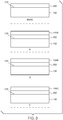
- Figure 3 illustrates cross-sectional views of four embodiments of the fan system 100.
- the four embodiments illustrate four sample configurations of materials that are subject to scratch tests (results illustrated in Figure 4 ) and corrosion tests (results illustrated in Figures 5 , 6 , and 7 ).
- a Base sample illustrates the steel fan mid shaft 102 with a coating 302 (e.g., anti-corrosion coating) that is applied to the inner diameter surface 108.
- the Base sample is devoid a dry film lubricant.
- Sample A illustrates the steel fan mid shaft 102 with the coating 302 applied to the inner diameter surface 108 and a first dry film lubricant 104A that is applied to the coating 302.
- the first dry film lubricant 104A may have a first chemical composition that includes a lead-based molybdenum disulfide.
- Sample B illustrates the steel fan mid shaft 102 with the coating 302 applied to the inner diameter surface 108 and a second dry film lubricant 104B that is applied to the coating 302.
- the second dry film lubricant 104B may have a different chemical composition that includes a lead-free molybdenum disulfide (e.g., with or without additional alloying elements such as, but not limited to, antimony (Sb) or Sb-based compounds).
- a lead-free molybdenum disulfide e.g., with or without additional alloying elements such as, but not limited to, antimony (Sb) or Sb-based compounds.
- Sample C illustrates the steel fan mid shaft 102 with the coating 302 applied to the inner diameter surface 108 and a third dry film lubricant 104C that is applied to the coating 302.
- the third dry film lubricant 104C may have a different chemical composition that includes a ⁇ 0.06% lead molybdenum disulfide (e.g., with or without additional alloying elements such as, but not limited to, antimony (Sb) or Sb-based compounds).
- one or more of the Base, Sample A, Sample B, or Sample C may include an additional sealant (not shown) that may be applied to the coating 302.
- a sealant may be applied between the coating 302 and the dry film lubricants 104A, 104B, 104C, respectively, of Samples A, B, and/or C.
- the sealant may be a non-porous sealant that provides a barrier against carbon deposits and extend the life of steel fan mid shaft 102 and the coating 302 relative to an embodiment that is devoid of the sealant.
- inventions illustrated in Figures 3 through 7 illustrate four samples of materials that may be subject to scratch and corrosion tests. Additionally or alternatively, more than four or less than four sets of materials may be tested.
- the dry film lubricants may have any alternative chemical compositions.
- a scratch indenter (not shown) applies a load ranging from 0 newtons (N) up to and including 1600 N to each of the four samples.
- the scratch indenter may be manufactured of the same metallic alloy, including a copper-nickel-indium coating (or another applied low-coefficient of friction coating), as the supports (130, 132, 134) in order to simulate the tribological contact between the outer diameter surface 140 of the supports 130, 132, 134 and the inner diameter surface 108 of the fan mid shaft 102 when the supports 130, 132, 134 are inserted into the fan mid shaft 102.
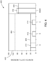
- Figure 4 illustrates a scratch depth graph 400 in accordance with one embodiment.
- a vertical axis 402 is representative of a scratch depth magnitude (in microns) that is measured on each of the four samples (Base, A, B, C, and D of Figure 3 ).
- a horizontal line 406 is representative of an average thickness of a dry film lubricant (104A, 104B, 104C) that is applied to the samples A, B, and C. For example, the average thickness of the dry film lubricant is about 20 microns.
- a horizontal line 404 is representative an average thickness of the coating 302 that is applied to the samples Base, A, B, and C. For example, the average thickness of the coating 302 is about 75 microns.
- the 75 microns thick coating 302 (illustrated as the solid horizontal line 404) is applied onto the 20 microns thick dry film lubricant of samples A, B, and C.
- the 75 microns thick coating 302 (illustrated as the dotted horizontal line 404) is applied to the bare inner diameter surface 108 of the fan mid shaft 102.
- the steel material of the inner diameter surface 108 of the fan mid shaft 102 is reached (e.g., exposed).
- the bare steel material of the fan mid shaft 102 may be subject to galvanic corrosion.
- the sample A (e.g., the steel fan mid shaft, coating 302, and lead-based dry film lubricant 104A) has a first scratch depth 410 that is about 20 microns deep. For example, the first scratch depth 410 reaches a scratch depth that is substantially the same as the average thickness 406 of the dry film lubricant.
- the sample B (e.g., the steel fan mid shaft, coating 302, and lead-free dry film lubricant 104B) has a second scratch depth 412 that is about 12 microns deep. For example, the second scratch depth 412 is less than (e.g., not as deep, more shallow than) the average thickness 406 of the dry film lubricant.
- the scratch test performed on sample B does not reach or expose the coating 302 (e.g., at a depth greater than 20 microns).
- the sample C e.g., the steel fan mid shaft, coating 302, and 0.06% lead dry film lubricant 104C
- the scratch test performed on sample C does not reach or expose the coating 302 (e.g., at a depth greater than 20 microns).
- the Base sample e.g., the steel fan mid shaft and coating 302
- the base scratch depth 416 is greater than (e.g., deeper than) the average thickness 404 of the coating 302.
- the scratch test performed on the Base sample reaches and exposes the bare steel material (e.g., the base scratch depth 416 is greater/deeper than 75 microns) of the fan mid shaft 102.
- Graph 400 illustrates that the dry film lubricants 104A, 104B, and 104C provide an improved scratch resistance to the indenter relative to the Base sample that does not have a dry film lubricant.
- the dry film lubricant reduces a depth of a scratch that is disposed on the inner diameter surface 108 of the shaft 102 relative to a system that is without the dry film lubricant.
- Each of the four samples are also subject to a corrosion test.
- a scribe that has a scribe depth of at least 140 microns is made on each of the four samples A, B, C, and Base. For example, the scribe depth reaches (e.g., exposes) the base steel material of the fan mid shaft 102.
- the samples are individually immersed and maintained in a 1wt% acetic acid solution. Additionally or alternatively, the samples may be immersed in an alternative acidic solution that may be prepared in an aqueous medium, oil, or a combination of both, at room temperature and/or at elevated temperatures up to and including 800°F.
- Figures 5 , 6 and 7 illustrate the results of the samples A, B, C and Base that are subjected to the corrosion test.
- FIG. 5 illustrates a pH corrosion graph 500 in accordance with one embodiment.
- a vertical axis 502 is representative of relative units of pH, and a horizontal axis 504 is representative of time (e.g., days).
- An increase in the pH level of the acidic solution corresponds to an increase in corrosion activity.
- the corrosion graph 500 illustrates that as the time increases, the pH level of the Base sample is greater than the pH level of samples A, B, and C. For example, at day 3, the pH level for each sample (Base, A, B, and C) is from about 2.5 to 2.8. At day 14, the pH level for the samples A, B and C is about 2.9, and the pH level for the Base sample is about 3.7.
- Samples A, B, and C, having the dry film lubricant have a lower increase in pH relative to the Base sample that is without a dry film lubricant.
- the amount of corrosive activity in the samples that include dry film lubricant increases slower than the corrosive activity in the Base sample that does not include a dry film lubricant.
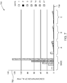
- Figure 6 illustrates an iron (Fe) release concentration graph 600 indicating corrosion activity and rate of corrosion in accordance with one embodiment.
- a vertical axis 602 is representative of a concentration of released of iron (Fe) measured in parts per million (ppm) in the acidic solution.
- a horizontal axis 604 is representative of measurements of each of the samples A, B, C and the Base sample over time (days).
- a greater level of concentration of iron (Fe) that is measured in the acidic solution is representative of increasing amounts of corrosion activity of the steel fan mid shaft.
- the measured amount of Fe in the acidic solution in which the Base sample is immersed in at day 10 is about 100ppm, at day 14 the measured amount of Fe is about 325ppm, and at day 20 the measured amount of Fe is about 850ppm.
- the measured amount of Fe in the acidic solution in which the sample A is immersed in at day 10 is about 25ppm, at day 14 the measured amount of Fe is about 50ppm, and at day 20 the measured amount of Fe is about 75ppm.
- the measured amount of Fe (e.g., the release of Fe into the acidic solution) in the acidic solution in which the samples A, B and C are immersed is less than 100ppm up to at least day 27.
- the measured amount of Fe in the acidic solution in which the Base sample is immersed is greater than 800ppm up to at least day 20.
- the measured amount of Fe that is released in the acidic solution of samples A, B and C is less than the measured amount of Fe that is released in the acidic solution of the Base sample.
- the graph 600 illustrates that a fan mid shaft that has a dry film lubricant applied to the coated steel surface of the shaft reduces the amount of galvanic corrosion activity relative to a fan mid shaft that is devoid a dry film lubricant applied to the coated steel material of the shaft.
- Figure 7 illustrates an aluminum (Al) release concentration graph 700 indicating corrosion activity and rate of corrosion in accordance with one embodiment.
- a vertical axis 702 is representative of a concentration of released Aluminum (Al) measured in parts per million (ppm) in the acidic solution.
- a horizontal axis 704 is representative of measurements of each of the samples A, B, C and the Base sample over time (days).
- a greater level of concentration of aluminum (Al) that is measured in the acidic solution is representative of increasing amounts of corrosion activity of the coating (e.g., coating 302).
- the measured amount of Al in the acidic solution in which the Base sample is immersed in at day 10 is about 35ppm, at day 14 the measured amount of Fe is about 65ppm, and at day 20 the measured amount of Fe is about 130ppm.
- the measured amount of Al in the acidic solution in which the sample A is immersed in at day 10 is about 2ppm, at day 14 the measured amount of Al is about 3ppm, and at day 20 the measured amount of Al is about 5ppm.
- the measured amount of Al (e.g., the release of Al into the acidic solution) in the acidic solution in which the samples A, B and C are immersed is less than 10ppm up to at least day 27.
- the measured amount of Al in the acidic solution in which the Base sample is immersed is greater than 120ppm up to at least day 20.
- the measured amount of Al that is released in the acidic solution of samples A, B and C is less than the measured amount of Al that is released in the acidic solution of the Base sample.
- the graph 700 illustrates that a fan mid shaft that has a dry film lubricant applied to the coated steel surface of the shaft reduces the amount of galvanic corrosion activity to the coating relative to a fan mid shaft that is devoid a dry film lubricant applied to the coated steel material of the shaft.
- Figures 5 through 7 illustrate that the dry film lubricant 104 that is applied to the inner diameter surface 108 of the coated steel material of the fan mid shaft 102 reduces an amount of corrosion on the inner diameter surface 108 of the fan mid shaft 102 relative to a system that is without a dry film lubricant.
- the higher values of the measured amounts of Fe and Al released in the acidic solution of the Base sample relative to the lower values of the measured amounts of Fe and Al released in the acidic solutions of the samples A, B, and C indicate that the dry film lubricant mitigates corrosion activity on the coated steel material of the fan mid shaft 102.
- the dry film lubricant increases a durability of the coated steel material relative to a coated steel material that is without a dry film lubricant.
- a fan system of a turbine includes a fan mid shaft made of a coated steel material configured to extend along a center axis of a turbine.
- the fan mid shaft having an inner diameter surface.
- the fan system includes a dry film lubricant that is configured to be applied to at least a portion of the inner diameter surface of the fan mid shaft.
- the dry film lubricant is a lead-free dry film lubricant.
- the fan system includes a central vent tube and one or more supports configured to be inserted into the shaft.
- the one or more supports are configured to maintain a position of the central vent tube within the shaft.
- the one or more supports are configured to be disposed at one or more positions within the shaft along the center axis of the turbine.
- the one or more supports include a forward support, a mid-support, and an aft support.
- the forward support is disposed at a forward-section of the shaft
- the mid-support is disposed at a mid-section of the shaft
- the aft support is disposed at an aft section of the shaft.
- the shaft is configured to be made of one or more of coated low-carbon steel, coated medium-carbon steel, or coated high-carbon steel.
- the fan system includes a scratch disposed on the inner diameter surface of the shaft.
- the dry film lubricant is configured to reduce a depth of the scratch disposed on the inner diameter surface of the shaft relative to a system without the dry film lubricant.
- the dry film lubricant is configured to reduce an amount of galvanic corrosion on the inner diameter surface of the shaft relative to a system without the dry film lubricant.
- the fan system includes a fan and a low-pressure turbine.
- the shaft is operably coupled with the fan at a forward-section of the shaft, and the shaft is operably coupled to the low-pressure turbine at an aft-section of the shaft.
- the dry film lubricant is one or more of molybdenum disulfide, polytetrafluoroethylene, or a combination of molybdenum disulfide and polytetrafluoroethylene.
- a method includes applying a dry film lubricant to at least a portion of an inner diameter surface of a fan mid shaft that extends along a center axis of a turbine.
- the fan mid shaft is configured to be made of a coated steel material.
- the dry film is configured to one or more of prevent scratch formation on the inner diameter surface of the shaft or mitigate galvanic corrosion on the inner diameter surface of the shaft.
- the dry film lubricant is a lead-free dry film lubricant.
- the method includes maintaining a position of a central vent tube within the fan mid shaft with one or more supports.
- the method includes disposing the one or more supports at one or more positions within the shaft along the center axis of the turbine.
- the method includes disposing a forward support of the one or more supports at a forward-section of the shaft, disposing a mid-support of the one or more supports at a mid-section of the shaft, and disposing an aft support of the one or more supports at an aft-section of the shaft.
- the shaft is made of one or more of coated low-carbon steel, coated medium-carbon steel, or coated high-carbon steel.
- the method includes reducing a depth of a scratch disposed on the inner diameter surface of the shaft with the dry film lubricant relative to a system without the dry film lubricant.
- the method includes reducing an amount of galvanic corrosion on the inner diameter surface of the shaft relative to a system without the dry film lubricant.
- the method includes operably coupling a fan with the shaft at a forward-section of the shaft, and operably coupling a low-pressure turbine with the shaft at an aft-section of the shaft.
- thy dry film lubricant is one or more of molybdenum disulfide, polytetrafluoroethylene, or a combination of molybdenum disulfide and polytetrafluoroethylene.
- a fan system of a turbine includes a fan mid shaft made of a coated steel material configured to extend along a center axis.
- the fan mid shaft has an inner diameter surface.
- the fan system includes a central vent tube that is configured to be inserted into the shaft to a position, wherein the position of the central vent tube is configured to be maintained by one or more supports that are disposed at one or more positions within the shaft along the center axis.
- the fan system includes a dry film lubricant that is applied to at least a portion of the inner diameter surface of the fan mid shaft.
Landscapes
- Engineering & Computer Science (AREA)
- Mechanical Engineering (AREA)
- General Engineering & Computer Science (AREA)
- Chemical & Material Sciences (AREA)
- Combustion & Propulsion (AREA)
- Structures Of Non-Positive Displacement Pumps (AREA)
Abstract
Description
- The subject matter described herein relates to turbines.
- A fan mid shaft assembly of a turbine includes the installation titanium central vent tube support rings that are disposed in a forward section, mid-section, and aft-section of the fan mid shaft, respectively. The supports are integral in maintaining a position of a central vent tube that extends within the fan mid shaft between a fan and a low-pressure turbine. The central vent tube may provide a pathway between the fan and the low-pressure turbine in order to remove the exhaust of leaked oil from the turbine. As the need increases for turbines to produce greater amounts of thrust, the fan mid shaft is subjected to increasing operating temperatures, rotational speeds, forces, and loads.
- One issue with known fan mid shaft assemblies is scratches or cracks that may be formed in the coating system of the shaft bore when the supports are installed into the fan mid shaft. Under increasing temperatures, forces, and loads, these coating defects (e.g., cracks, scratches, or the like) that are formed may grow until the fan mid shaft has a material failure. Additionally, in the presence of any leaked lubricant oil from the central vent tube (e.g., oil may become acidic at increasing temperatures and prolonged exposure), the coating defects may become local and/or general sites of corrosion initiation. These coating defects that are formed on the inner diameter surface of the shaft leave the steel material of the shaft exposed. The increasing temperature values of the turbine, increasing loads and forces on the shaft, and the presence of acidic environments also promote the growth of galvanic corrosion on the shaft at different locations along the shaft. The presence and growth of coating defects, corrosion sites and galvanic corrosion may reduce part life of the fan mid shaft assembly below acceptable levels, which may lead to increasing maintenance costs or potential catastrophic failure. Therefore, an improved coating system for a fan system may improve the durability of the fan system, and thereby reduce scratch formation and mitigate galvanic corrosion.
- In one aspect, a fan system of a turbine includes a fan mid shaft made of a coated steel material configured to extend along a center axis of a turbine. The fan mid shaft having an inner diameter surface. The fan system includes a dry film lubricant that is configured to be applied to at least a portion of the inner diameter surface of the fan mid shaft.
- In another aspect, a method includes applying a dry film lubricant to at least a portion of an inner diameter surface of a fan mid shaft that extends along a center axis of a turbine. The fan mid shaft is configured to be made of a coated steel material. The dry film is configured to one or more of prevent scratch formation on the inner diameter surface of the shaft or mitigate galvanic corrosion on the inner diameter surface of the shaft.
- In another aspect, a fan system of a turbine includes a fan mid shaft made of a coated steel material configured to extend along a center axis. The fan mid shaft has an inner diameter surface. The fan system includes a central vent tube that is configured to be inserted into the shaft to a position, wherein the position of the central vent tube is configured to be maintained by one or more supports that are disposed at one or more positions within the shaft along the center axis. The fan system includes a dry film lubricant that is applied to at least a portion of the inner diameter surface of the fan mid shaft.
- The present inventive subject matter will be better understood from reading the following description of non-limiting embodiments, with reference to the attached drawings, wherein below:
-
Figure 1 illustrates a perspective view of a fan mid shaft of a fan system in accordance with one embodiment; -
Figure 2 illustrates a cross-sectional view of the fan system ofFigure 1 in accordance with one embodiment; -
Figure 3 illustrates cross-sectional views of a fan system in accordance with one embodiment; -
Figure 4 illustrates a scratch depth graph in accordance with one embodiment; -
Figure 5 illustrates a pH concentration graph indicating a corrosion rate in accordance with one embodiment; -
Figure 6 illustrates a concentration graph indicating a corrosion rate in accordance with one embodiment; and -
Figure 7 illustrates a corrosion graph in accordance with one embodiment. - One or more embodiments of the inventive subject matter described herein relates to systems and methods that reduce a depth of a scratch that may be formed on an inner diameter surface of a fan mid shaft during the installation of a central vent tube support by applying a dry film lubricant to the inner diameter surface of a coated steel material of the fan mid shaft. For example, the dry film lubricant may provide a low coefficient of friction between the supports and the shaft, thereby preventing the formation of axial assembly scratches or cracks.
- One or more embodiments of the inventive subject matter described herein relates to system and methods that mitigate galvanic corrosion to the fan mid shaft. For example, anti-corrosion coating that is applied to the steel shaft may be a porous material that provides a pathway for electrolytes to access the underlying steel substrate of the shaft. In an acidic environment, the coating may not dissolve which allows the electrolytes to attack and corrode the underlying steel. A hydrophobic dry film lubricant that is applied to the inner diameter surface of the coated steel material of the fan mid shaft provides a hermetic seal on the porous anti-corrosion coating thereby preventing any electrolyte ingress through the coating and preventing steel shaft corrosion.
-
Figure 1 illustrates a perspective view of afan system 100 in accordance with one embodiment.Figure 2 illustrates a cross-sectional view of thefan system 100 in accordance with one embodiment.Figures 1 and2 will be described together in detail. - The
fan system 100 includes afan mid shaft 102 that has a substantially circular cross-sectional shape. Thefan mid shaft 102 is tubular between afirst end 112 and an oppositesecond end 114 along acenter axis 106. Thefan mid shaft 102 has aninner diameter surface 108 and anouter diameter surface 110. In the illustrated embodiment, theinner diameter surface 108 and theouter diameter surface 110 are substantially concentric about thecentral axis 106. Additionally or alternatively, one or more of theinner diameter surface 108 or theouter diameter surface 110 may not be substantially concentric about thecentral axis 106, may have uniform or non-uniform cross-sectional shapes, may have uniform or non-uniform shapes along the length of thecenter axis 106, or the like. For example, theinner diameter surface 108 may have a polygon cross-sectional shape (e.g., rectangular, hexagonal, trapezoidal, or the like) and theouter diameter surface 110 may have a circular cross-sectional shape. - The
fan mid shaft 102 is manufactured out of a steel alloy in one embodiment. For example, theshaft 102 may be manufactured out of any grade of heat treated and/or alloyed steel including, but not limited to, low-carbon steel, medium-carbon steel, high-carbon steel, or the like. For example, theshaft 102 may be manufactured of a coated low, medium, or high carbon steel with additional alloying elements that may include but are not limited to chromium, nickel, cobalt, molybdenum, aluminum, titanium, or the like. Additionally or alternatively, theshaft 102 may be manufactured out of another material such as alloys of titanium, nickel, or alternative elements. A coating is applied to the steelfan mid shaft 102. For example, the coating (not shown) may be a porous, non-sacrificial, non-dissolvable, and unburnished anti-corrosion coating material. A porous coating may have minute spaces or holes through which liquid or air may pass. A non-sacrificial coating may be a permanent or semi-permanent material that may withstand high temperatures, high humidity levels, or the like. A non-dissolvable coating may not be metabolized, melt, liquify, disintegrate, fade, or the like. An unburnished coating may be unpolished, dull, or the like. Additionally or alternatively, the coating may be another material having other properties. For example, the coating may be a non-porous material, the coating may be a sacrificial material, the coating may be a dissolvable material, the coating may be a burnished material, or the like. The coating may be applied to the all or a portion of theinner diameter surface 108 of thefan mid shaft 102, may be applied to all or a portion of theouter diameter surface 110, or any combination therein, in order to protect the steel material of thefan mid shaft 102. - In one or more embodiments, the
fan mid shaft 102 may be used in one or more applications that may expose the coatedsteel shaft 102 to acidic environments. For example, the acidic environment may have one or more carboxylic acids (e.g., acetic acid, valeric acid, propionic acid, lactic acid, or the like), may be exposed to moist and/or dry environments, environments having chlorides or alternatively chemical species, or the like. Additionally or alternatively, thefan system 100 may be exposed to temperatures up to and including 100°F, up to and including 250°F, up to and including 500°F, up to and including 750°F, up to and including 1000°F, or the like. - A
dry film lubricant 104 is applied to theinner diameter surface 108 of the fanmid shaft 102. Thedry film lubricant 104 may be applied to at least a portion of theinner diameter surface 108, all of theinner diameter surface 108, or the like. For example, the dry film lubricant may be applied to the coated steel fanmid shaft 102, or may be applied to a non-coated steel fanmid shaft 102. Examples of non-limiting processes for applying thedry film lubricant 104 to theinner diameter surface 108 may include spraying, immersing, dipping, burnishing, or the like, with or without a subsequent high temperature curing process. Non-limiting examples of the chemical composition of the dry film lubricant may be lead based, lead free, molybdenum disulfide based (e.g., with or without the presence of graphite), polytetrafluoroethylene based (e.g., with or without the presence of graphite), a mix of molybdenum disulfide and polytetrafluoroethylene based (e.g., with or without the presence of graphite), tungsten disulfide based, or the like. Additionally, thedry film lubricant 104 may include graphite, may not include graphite, may be solvent based, may be water based, or the like. In one or more embodiments, thedry film lubricant 104 may be a hydrophobic dry film lubricant that may provide a hermetic seal on the porous coating that is disposed onto theinner diameter surface 108 of theshaft 102. For example, thedry film lubricant 104 may prevent, mitigate, or reduce a formation of cracks and/or an amount of corrosion on theinner diameter surface 108 of theshaft 102 relative to a system that is without a dry film lubricant. The preventing, mitigation, reduction, or the like, of the formation of cracks and an amount of corrosion will be discussed in detail below. - The fan
mid shaft 102 is operably coupled with afan 116 at thefirst end 112 of theshaft 102. Additionally, the fanmid shaft 102 is operably coupled with a low-pressure turbine 118 at thesecond end 114 of theshaft 102. For example, in the illustrated embodiment, thefan system 100 may be used in a turbine in order to transfer energy between the low-pressure turbine 118 and thefan 116. Additionally or alternatively, thefan system 100 may be operably coupled with one or more alternative components of a turbine, a pump, or any alternative system. For example, the fanmid shaft 102 may be disposed between and operably coupled with one or more static or dynamic components of any alternative system. In one or more embodiments, the fanmid shaft 102 may be exposed to torque loading conditions up to and including 5 kilonewton-meters (kN-m), 10 kN-m, 20 kN-m, 50 kN-m, or the like. Additionally or alternatively, the fanmid shaft 102 may be exposed to normal forces (e.g., sliding conditions) up to and including 1 kilonewton (kN), 2 kN, 5 kN, 10 kN, or the like. - The
fan system 100 has acentral vent tube 126 that is disposed inside of the fanmid shaft 102. Thecentral vent tube 126 has a tubular shape between afirst end 136 and asecond end 138 of thecentral vent tube 126 along thecenter axis 106. Optionally, thecentral vent tube 126 may extend a uniform length as the fanmid shaft 102, may extend a length that is shorter than the length of the fanmid shaft 102, or the like. Thecentral vent tube 126 may provide a pathway between thefan 116 and the low-pressure turbine 118 in order to remove the exhaust of leaked oil from the turbine. - In one or more embodiments, the
central vent tube 126 may be manufactured out of a steel alloy. For example, thecentral vent tube 126 may be manufactured out of any grade of heat treated and/or alloyed steel including but not limited to low-carbon steel, medium-carbon steel, high-carbon steel, or the like. For example, thecentral vent tube 126 may be manufactured out of stainless steel, an alloy of titanium, or any alloy of an alternative element. Optionally, thecentral vent tube 126 and the fanmid shaft 102 may be manufactured out of uniform steel alloys or non-uniform steel alloys. - In one or more embodiments, the fan
mid shaft 102 may be divided into three section lengths along thecenter axis 106 between the first and second ends 112, 114. The three segments include a forward-section 120 that is disposed near thefirst end 112 of theshaft 102, an aft-section 124 that is disposed near thesecond end 114 of theshaft 102, and a mid-section 122 that is disposed between the forward-section 120 and the aft-section 124 along thecenter axis 106. In the illustrated embodiment, the lengths of the forward-section 120, mid-section 122, and aft-section 124 are substantially uniform between the first and second ends 112, 114. Optionally, the fanmid shaft 102 may be divided into three non-uniform sections, less than three or more than three uniform or non-uniform sections, or any combination therein. - The
central vent tube 126 is held in a position within the fanmid shaft 102 along thecenter axis 106 by one or more supports. For example, in the illustrated embodiment, the position of thecentral vent tube 126 within the fanmid shaft 102 is maintained by threesupports shaft 102. Optionally, the position of thecentral vent tube 126 may be maintained by less than three or more than three supports. Thesupports mid shaft 102. In the illustrated embodiment, thesupports supports supports outer diameter surface 140 of the supports. For example, the coating may be a copper-nickel-indium coating, or an alternative coating having a low coefficient of friction such as a lubricant coating, and is applied to a portion or all of theouter diameter surface 140 of each of thesupports - The three supports include a
forward support 130 that is disposed at the forward-section 120 of theshaft 102, a mid-support 132 that is disposed at the mid-section 122 of theshaft 102, and anaft support 134 that is disposed at the aft-section 124 of theshaft 102. The threesupports mid shaft 102 at thesecond end 114 of theshaft 102 and transferred in a direction A into the position at the forward-section 120, mid-section 122, and aft-section 124, respectively. - Inserting the supports involves a tribological contact between the outer diameter surfaces 140 of each of the supports and the
inner diameter surface 108 of the fanmid shaft 102. For example, thesupports mid shaft 102 by a torque load and/or compressive load application that may cause damage (e.g., crush, crack, compressive damage, or the like) to theinner diameter surface 108 of the fanmid shaft 102. The tribological contact may result in the formation of scratches, cracks, or the like, in the coated steelinner diameter surface 108 of theshaft 102. Additionally, the steel alloy of the fanmid shaft 102 may be subjected to a corrosion or chemical attack (e.g., galvanic corrosion) when the underlying steel alloy of theshaft 102 is exposed due to the formation of scratches, cracks, or the like.Figures 3 through 7 demonstrate that thedry film lubricant 104 improves the resistance of the fanmid shaft 102 to chemical attacks, electrochemical corrosion, oxidation, wear, or the like, relative to afan system 100 that is devoid a dry film lubricant that is applied to theinner diameter surface 108 of theshaft 102. For example, the dry film lubricant may provide improved protection and/or resistance to the compressive loading of thesupports inner diameter surface 108 of the fanmid shaft 102. -
Figure 3 illustrates cross-sectional views of four embodiments of thefan system 100. The four embodiments illustrate four sample configurations of materials that are subject to scratch tests (results illustrated inFigure 4 ) and corrosion tests (results illustrated inFigures 5 ,6 , and7 ). A Base sample illustrates the steel fanmid shaft 102 with a coating 302 (e.g., anti-corrosion coating) that is applied to theinner diameter surface 108. For example, the Base sample is devoid a dry film lubricant. Sample A illustrates the steel fanmid shaft 102 with thecoating 302 applied to theinner diameter surface 108 and a firstdry film lubricant 104A that is applied to thecoating 302. For example, the firstdry film lubricant 104A may have a first chemical composition that includes a lead-based molybdenum disulfide. Sample B illustrates the steel fanmid shaft 102 with thecoating 302 applied to theinner diameter surface 108 and a seconddry film lubricant 104B that is applied to thecoating 302. For example, the seconddry film lubricant 104B may have a different chemical composition that includes a lead-free molybdenum disulfide (e.g., with or without additional alloying elements such as, but not limited to, antimony (Sb) or Sb-based compounds). Sample C illustrates the steel fanmid shaft 102 with thecoating 302 applied to theinner diameter surface 108 and a thirddry film lubricant 104C that is applied to thecoating 302. For example, the thirddry film lubricant 104C may have a different chemical composition that includes a <0.06% lead molybdenum disulfide (e.g., with or without additional alloying elements such as, but not limited to, antimony (Sb) or Sb-based compounds). - Optionally, in one or more embodiments, one or more of the Base, Sample A, Sample B, or Sample C may include an additional sealant (not shown) that may be applied to the
coating 302. For example, a sealant may be applied between thecoating 302 and thedry film lubricants mid shaft 102 and thecoating 302 relative to an embodiment that is devoid of the sealant. - The embodiments illustrated in
Figures 3 through 7 illustrate four samples of materials that may be subject to scratch and corrosion tests. Additionally or alternatively, more than four or less than four sets of materials may be tested. Optionally, the dry film lubricants may have any alternative chemical compositions. - Each of the four samples are subject to a scratch test. A scratch indenter (not shown) applies a load ranging from 0 newtons (N) up to and including 1600 N to each of the four samples. The scratch indenter may be manufactured of the same metallic alloy, including a copper-nickel-indium coating (or another applied low-coefficient of friction coating), as the supports (130, 132, 134) in order to simulate the tribological contact between the
outer diameter surface 140 of thesupports inner diameter surface 108 of the fanmid shaft 102 when thesupports mid shaft 102. -
Figure 4 illustrates ascratch depth graph 400 in accordance with one embodiment. Avertical axis 402 is representative of a scratch depth magnitude (in microns) that is measured on each of the four samples (Base, A, B, C, and D ofFigure 3 ). Ahorizontal line 406 is representative of an average thickness of a dry film lubricant (104A, 104B, 104C) that is applied to the samples A, B, and C. For example, the average thickness of the dry film lubricant is about 20 microns. Ahorizontal line 404 is representative an average thickness of thecoating 302 that is applied to the samples Base, A, B, and C. For example, the average thickness of thecoating 302 is about 75 microns. The 75 microns thick coating 302 (illustrated as the solid horizontal line 404) is applied onto the 20 microns thick dry film lubricant of samples A, B, and C. Alternatively, the 75 microns thick coating 302 (illustrated as the dotted horizontal line 404) is applied to the bareinner diameter surface 108 of the fanmid shaft 102. At a depth greater than 75 microns, the steel material of theinner diameter surface 108 of the fanmid shaft 102 is reached (e.g., exposed). For example, when the bare steel material of the fanmid shaft 102 is exposed, the bare steel material may be subject to galvanic corrosion. - The sample A (e.g., the steel fan mid shaft, coating 302, and lead-based
dry film lubricant 104A) has afirst scratch depth 410 that is about 20 microns deep. For example, thefirst scratch depth 410 reaches a scratch depth that is substantially the same as theaverage thickness 406 of the dry film lubricant. The sample B (e.g., the steel fan mid shaft, coating 302, and lead-freedry film lubricant 104B) has asecond scratch depth 412 that is about 12 microns deep. For example, thesecond scratch depth 412 is less than (e.g., not as deep, more shallow than) theaverage thickness 406 of the dry film lubricant. The scratch test performed on sample B does not reach or expose the coating 302 (e.g., at a depth greater than 20 microns). The sample C (e.g., the steel fan mid shaft, coating 302, and 0.06% leaddry film lubricant 104C) has athird scratch depth 414 that is about 14 microns deep. For example, thethird scratch depth 414 is less than (e.g., not as deep, more shallow than) theaverage thickness 406 of the dry film lubricant. The scratch test performed on sample C does not reach or expose the coating 302 (e.g., at a depth greater than 20 microns). The Base sample (e.g., the steel fan mid shaft and coating 302) has abase scratch depth 416 that is about 85 microns deep. For example, thebase scratch depth 416 is greater than (e.g., deeper than) theaverage thickness 404 of thecoating 302. The scratch test performed on the Base sample reaches and exposes the bare steel material (e.g., thebase scratch depth 416 is greater/deeper than 75 microns) of the fanmid shaft 102.Graph 400 illustrates that thedry film lubricants inner diameter surface 108 of theshaft 102 relative to a system that is without the dry film lubricant. - Each of the four samples (e.g., new samples that were not used in the scratch test) are also subject to a corrosion test. A scribe that has a scribe depth of at least 140 microns is made on each of the four samples A, B, C, and Base. For example, the scribe depth reaches (e.g., exposes) the base steel material of the fan
mid shaft 102. The samples are individually immersed and maintained in a 1wt% acetic acid solution. Additionally or alternatively, the samples may be immersed in an alternative acidic solution that may be prepared in an aqueous medium, oil, or a combination of both, at room temperature and/or at elevated temperatures up to and including 800°F.Figures 5 ,6 and7 illustrate the results of the samples A, B, C and Base that are subjected to the corrosion test. -
Figure 5 illustrates apH corrosion graph 500 in accordance with one embodiment. Avertical axis 502 is representative of relative units of pH, and ahorizontal axis 504 is representative of time (e.g., days). An increase in the pH level of the acidic solution corresponds to an increase in corrosion activity. Thecorrosion graph 500 illustrates that as the time increases, the pH level of the Base sample is greater than the pH level of samples A, B, and C. For example, atday 3, the pH level for each sample (Base, A, B, and C) is from about 2.5 to 2.8. Atday 14, the pH level for the samples A, B and C is about 2.9, and the pH level for the Base sample is about 3.7. Samples A, B, and C, having the dry film lubricant, have a lower increase in pH relative to the Base sample that is without a dry film lubricant. For example, the amount of corrosive activity in the samples that include dry film lubricant increases slower than the corrosive activity in the Base sample that does not include a dry film lubricant. -
Figure 6 illustrates an iron (Fe)release concentration graph 600 indicating corrosion activity and rate of corrosion in accordance with one embodiment. Avertical axis 602 is representative of a concentration of released of iron (Fe) measured in parts per million (ppm) in the acidic solution. Ahorizontal axis 604 is representative of measurements of each of the samples A, B, C and the Base sample over time (days). A greater level of concentration of iron (Fe) that is measured in the acidic solution is representative of increasing amounts of corrosion activity of the steel fan mid shaft. - The measured amount of Fe in the acidic solution in which the Base sample is immersed in at
day 10 is about 100ppm, atday 14 the measured amount of Fe is about 325ppm, and atday 20 the measured amount of Fe is about 850ppm. Alternatively, the measured amount of Fe in the acidic solution in which the sample A is immersed in atday 10 is about 25ppm, atday 14 the measured amount of Fe is about 50ppm, and atday 20 the measured amount of Fe is about 75ppm. The measured amount of Fe (e.g., the release of Fe into the acidic solution) in the acidic solution in which the samples A, B and C are immersed is less than 100ppm up to atleast day 27. Alternatively, the measured amount of Fe in the acidic solution in which the Base sample is immersed is greater than 800ppm up to atleast day 20. The measured amount of Fe that is released in the acidic solution of samples A, B and C is less than the measured amount of Fe that is released in the acidic solution of the Base sample. For example, thegraph 600 illustrates that a fan mid shaft that has a dry film lubricant applied to the coated steel surface of the shaft reduces the amount of galvanic corrosion activity relative to a fan mid shaft that is devoid a dry film lubricant applied to the coated steel material of the shaft. -
Figure 7 illustrates an aluminum (Al)release concentration graph 700 indicating corrosion activity and rate of corrosion in accordance with one embodiment. Avertical axis 702 is representative of a concentration of released Aluminum (Al) measured in parts per million (ppm) in the acidic solution. Ahorizontal axis 704 is representative of measurements of each of the samples A, B, C and the Base sample over time (days). A greater level of concentration of aluminum (Al) that is measured in the acidic solution is representative of increasing amounts of corrosion activity of the coating (e.g., coating 302). - The measured amount of Al in the acidic solution in which the Base sample is immersed in at
day 10 is about 35ppm, atday 14 the measured amount of Fe is about 65ppm, and atday 20 the measured amount of Fe is about 130ppm. Alternatively, the measured amount of Al in the acidic solution in which the sample A is immersed in atday 10 is about 2ppm, atday 14 the measured amount of Al is about 3ppm, and atday 20 the measured amount of Al is about 5ppm. The measured amount of Al (e.g., the release of Al into the acidic solution) in the acidic solution in which the samples A, B and C are immersed is less than 10ppm up to atleast day 27. Alternatively, the measured amount of Al in the acidic solution in which the Base sample is immersed is greater than 120ppm up to atleast day 20. The measured amount of Al that is released in the acidic solution of samples A, B and C is less than the measured amount of Al that is released in the acidic solution of the Base sample. For example, thegraph 700 illustrates that a fan mid shaft that has a dry film lubricant applied to the coated steel surface of the shaft reduces the amount of galvanic corrosion activity to the coating relative to a fan mid shaft that is devoid a dry film lubricant applied to the coated steel material of the shaft. -
Figures 5 through 7 illustrate that thedry film lubricant 104 that is applied to theinner diameter surface 108 of the coated steel material of the fanmid shaft 102 reduces an amount of corrosion on theinner diameter surface 108 of the fanmid shaft 102 relative to a system that is without a dry film lubricant. For example, the higher values of the measured amounts of Fe and Al released in the acidic solution of the Base sample relative to the lower values of the measured amounts of Fe and Al released in the acidic solutions of the samples A, B, and C indicate that the dry film lubricant mitigates corrosion activity on the coated steel material of the fanmid shaft 102. For example, the dry film lubricant increases a durability of the coated steel material relative to a coated steel material that is without a dry film lubricant. - In one embodiment of the subject matter described herein, a fan system of a turbine includes a fan mid shaft made of a coated steel material configured to extend along a center axis of a turbine. The fan mid shaft having an inner diameter surface. The fan system includes a dry film lubricant that is configured to be applied to at least a portion of the inner diameter surface of the fan mid shaft.
- Optionally, the dry film lubricant is a lead-free dry film lubricant.
- Optionally, the fan system includes a central vent tube and one or more supports configured to be inserted into the shaft. The one or more supports are configured to maintain a position of the central vent tube within the shaft. Optionally, the one or more supports are configured to be disposed at one or more positions within the shaft along the center axis of the turbine.
- Optionally, the one or more supports include a forward support, a mid-support, and an aft support. The forward support is disposed at a forward-section of the shaft, the mid-support is disposed at a mid-section of the shaft, and the aft support is disposed at an aft section of the shaft.
- Optionally, the shaft is configured to be made of one or more of coated low-carbon steel, coated medium-carbon steel, or coated high-carbon steel.
- Optionally, the fan system includes a scratch disposed on the inner diameter surface of the shaft. The dry film lubricant is configured to reduce a depth of the scratch disposed on the inner diameter surface of the shaft relative to a system without the dry film lubricant.
- Optionally, the dry film lubricant is configured to reduce an amount of galvanic corrosion on the inner diameter surface of the shaft relative to a system without the dry film lubricant.
- Optionally, the fan system includes a fan and a low-pressure turbine. The shaft is operably coupled with the fan at a forward-section of the shaft, and the shaft is operably coupled to the low-pressure turbine at an aft-section of the shaft.
- Optionally, the dry film lubricant is one or more of molybdenum disulfide, polytetrafluoroethylene, or a combination of molybdenum disulfide and polytetrafluoroethylene.
- In one embodiment of the subject matter described herein, a method includes applying a dry film lubricant to at least a portion of an inner diameter surface of a fan mid shaft that extends along a center axis of a turbine. The fan mid shaft is configured to be made of a coated steel material. The dry film is configured to one or more of prevent scratch formation on the inner diameter surface of the shaft or mitigate galvanic corrosion on the inner diameter surface of the shaft.
- Optionally, the dry film lubricant is a lead-free dry film lubricant.
- Optionally, the method includes maintaining a position of a central vent tube within the fan mid shaft with one or more supports. Optionally, the method includes disposing the one or more supports at one or more positions within the shaft along the center axis of the turbine.
- Optionally, the method includes disposing a forward support of the one or more supports at a forward-section of the shaft, disposing a mid-support of the one or more supports at a mid-section of the shaft, and disposing an aft support of the one or more supports at an aft-section of the shaft.
- Optionally, the shaft is made of one or more of coated low-carbon steel, coated medium-carbon steel, or coated high-carbon steel.
- Optionally, the method includes reducing a depth of a scratch disposed on the inner diameter surface of the shaft with the dry film lubricant relative to a system without the dry film lubricant.
- Optionally, the method includes reducing an amount of galvanic corrosion on the inner diameter surface of the shaft relative to a system without the dry film lubricant.
- Optionally, the method includes operably coupling a fan with the shaft at a forward-section of the shaft, and operably coupling a low-pressure turbine with the shaft at an aft-section of the shaft.
- Optionally, thy dry film lubricant is one or more of molybdenum disulfide, polytetrafluoroethylene, or a combination of molybdenum disulfide and polytetrafluoroethylene.
- In one embodiment of the subject matter described herein, a fan system of a turbine includes a fan mid shaft made of a coated steel material configured to extend along a center axis. The fan mid shaft has an inner diameter surface. The fan system includes a central vent tube that is configured to be inserted into the shaft to a position, wherein the position of the central vent tube is configured to be maintained by one or more supports that are disposed at one or more positions within the shaft along the center axis. The fan system includes a dry film lubricant that is applied to at least a portion of the inner diameter surface of the fan mid shaft.
- As used herein, an element or step recited in the singular and proceeded with the word "a" or "an" should be understood as not excluding plural of said elements or steps, unless such exclusion is explicitly stated. Furthermore, references to "one embodiment" of the presently described subject matter are not intended to be interpreted as excluding the existence of additional embodiments that also incorporate the recited features. Moreover, unless explicitly stated to the contrary, embodiments "comprising" or "having" an element or a plurality of elements having a particular property may include additional such elements not having that property.
- It is to be understood that the above description is intended to be illustrative, and not restrictive. For example, the above-described embodiments (and/or aspects thereof) may be used in combination with each other. In addition, many modifications may be made to adapt a particular situation or material to the teachings of the subject matter set forth herein without departing from its scope. While the dimensions and types of materials described herein are intended to define the parameters of the disclosed subject matter, they are by no means limiting and are exemplary embodiments. Many other embodiments will be apparent to those of skill in the art upon reviewing the above description. The scope of the subject matter described herein should, therefore, be determined with reference to the appended claims, along with the full scope of equivalents to which such claims are entitled. In the appended claims, the terms "including" and "in which" are used as the plain-English equivalents of the respective terms "comprising" and "wherein." Moreover, in the following claims, the terms "first," "second," and "third," etc. are used merely as labels, and are not intended to impose numerical requirements on their objects. Further, the limitations of the following claims are not written in means-plus-function format and are not intended to be interpreted based on 35 U.S.C. § 112(f), unless and until such claim limitations expressly use the phrase "means for" followed by a statement of function void of further structure.
- This written description uses examples to disclose several embodiments of the subject matter set forth herein, including the best mode, and also to enable a person of ordinary skill in the art to practice the embodiments of disclosed subject matter, including making and using the devices or systems and performing the methods. The patentable scope of the subject matter described herein is defined by the claims, and may include other examples that occur to those of ordinary skill in the art. Such other examples are intended to be within the scope of the claims if they have structural elements that do not differ from the literal language of the claims, or if they include equivalent structural elements with insubstantial differences from the literal languages of the claims.
- Various aspects and embodiments of the present invention are defined by the following numbered clauses:
- 1. A fan system of a turbine, the fan system comprising:
- a fan mid shaft made of a coated steel material configured to extend along a center axis of a turbine, the fan mid shaft having an inner diameter surface; and
- a dry film lubricant configured to be applied to at least a portion of the inner diameter surface of the fan mid shaft.
- 2. The fan system of
clause 1, wherein the dry film lubricant is a lead-free dry film lubricant. - 3. The fan system of any preceding clause, further comprising a central vent tube and one or more supports configured to be inserted into the shaft, wherein the one or more supports are configured to maintain a position of the central vent tube within the shaft.
- 4. The fan system of any preceding clause, wherein the one or more supports are configured to be disposed at one or more positions within the shaft along the center axis of the turbine.
- 5. The fan system of any preceding clause, wherein the one or more supports include a forward support, a mid-support, and an aft support, wherein the forward support is configured to be disposed at a forward-section of the shaft, wherein the mid-support is configured to be disposed at a mid-section of the shaft, and wherein the aft support is configured to be disposed at an aft-section of the shaft.
- 6. The fan system of any preceding clause, wherein the shaft is configured to be made of one or more of coated low-carbon steel, coated medium-carbon steel, or coated high-carbon steel.
- 7. The fan system of any preceding clause, further comprising a scratch disposed on the inner diameter surface of the shaft, wherein the dry film lubricant is configured to reduce a depth of the scratch disposed on the inner diameter surface of the shaft relative to a system without the dry film lubricant.
- 8. The fan system of any preceding clause, wherein the dry film lubricant is configured to reduce an amount of galvanic corrosion on the inner diameter surface of the shaft relative to a system without the dry film lubricant.
- 9. The fan system of any preceding clause, further comprising a fan and a low-pressure turbine, wherein the shaft is configured to be operably coupled with the fan at a forward-section of the shaft, and the shaft is configured to be operably coupled to the low-pressure turbine at an aft-section of the shaft.
- 10. The fan system of any preceding clause, wherein the dry film lubricant is configured to be one or more of molybdenum disulfide, polytetrafluoroethylene, or a combination of molybdenum disulfide and polytetrafluoroethylene.
- 11. A method comprising:
applying a dry film lubricant to at least a portion of an inner diameter surface of a fan mid shaft that extends along a center axis of a turbine, the fan mid shaft configured to be made of a coated steel material, wherein the dry film lubricant is configured to one or more of prevent scratch formation on the inner diameter surface of the shaft or mitigate galvanic corrosion on the inner diameter surface of the shaft. - 12. The method of any preceding clause, wherein the dry film lubricant is a lead-free dry film lubricant.
- 13. The method of any preceding clause, further comprising maintaining a position of a central vent tube within the fan mid shaft with one or more supports.
- 14. The method of any preceding clause, further comprising disposing the one or more supports at one or more positions within the shaft along the center axis of the turbine.
- 15. The method of any preceding clause, further comprising disposing a forward support of the one or more supports at a forward-section of the shaft, disposing a mid-support of the one or more supports at a mid-section of the shaft, and disposing an aft support of the one or more supports at an aft-section of the shaft.
- 16. The method of any preceding clause, wherein the shaft is configured to be made of one or more of coated low-carbon steel, coated medium-carbon steel, or coated high-carbon steel.
- 17. The method of any preceding clause, further comprising reducing a depth of a scratch disposed on the inner diameter surface of the shaft with the dry film lubricant relative to a system without the dry film lubricant.
- 18. The method of any preceding clause, further comprising reducing an amount of galvanic corrosion on the inner diameter surface of the shaft relative to a system without the dry film lubricant.
- 19. The method of any preceding clause, wherein the dry film lubricant is configured to be one or more of molybdenum disulfide, polytetrafluoroethylene, or a combination of molybdenum disulfide and polytetrafluoroethylene.
- 20. A fan system of a turbine, the fan system comprising:
- a fan mid shaft made of a coated steel material configured to extend along a center axis, the fan mid shaft having an inner diameter surface;
- a central vent tube configured to be inserted into the shaft to a position, wherein the position of the central vent tube is configured to be maintained by one or more supports configured to be disposed at one or more positions within the shaft along the center axis; and
- a dry film lubricant configured to be applied to at least a portion of the inner diameter surface of the fan mid shaft.
Claims (14)
- A fan system (100) of a turbine, the fan system (100) comprising:a fan mid shaft (102) made of a coated steel material configured to extend along a center axis (106) of a turbine, the fan mid shaft (102) having an inner diameter surface (108); anda dry film lubricant (104) configured to be applied to at least a portion of the inner diameter surface (108) of the fan mid shaft (102).
- The fan system (100) of claim 1, wherein the dry film lubricant (104) is a lead-free dry film lubricant.
- The fan system (100) of either of claim 1 or 2, further comprising a central vent tube (126) and one or more supports (130, 132, 134) configured to be inserted into the shaft (102), wherein the one or more supports (130, 132, 134) are configured to maintain a position of the central vent tube (126) within the shaft (102).
- The fan system (100) of claim 3, wherein the one or more supports (130, 132, 134) are configured to be disposed at one or more positions within the shaft (102) along the center axis (106) of the turbine.
- The fan system (100) of either of claim 3 or 4, wherein the one or more supports include a forward support (130), a mid-support (132), and an aft support (134), wherein the forward support (130) is configured to be disposed at a forward-section (120) of the shaft (102), wherein the mid-support (132) is configured to be disposed at a mid-section (122) of the shaft (102), and wherein the aft support (134) is configured to be disposed at an aft-section (124) of the shaft (102).
- The fan system (100) of any preceding claim, wherein the shaft (102) is configured to be made of one or more of coated low-carbon steel, coated medium-carbon steel, or coated high-carbon steel.
- The fan system (100) of any preceding claim, further comprising a scratch disposed on the inner diameter surface (108) of the shaft (102), wherein the dry film lubricant (104) is configured to reduce a depth of the scratch disposed on the inner diameter surface (108) of the shaft (102) relative to a system without the dry film lubricant (104).
- The fan system (100) of any preceding claim, wherein the dry film lubricant is configured to reduce an amount of galvanic corrosion on the inner diameter surface (108) of the shaft (102) relative to a system without the dry film lubricant (104).
- The fan system (100) of any preceding claim, further comprising a fan (116) and a low-pressure turbine (118), wherein the shaft (102) is configured to be operably coupled with the fan (116) at a forward-section (120) of the shaft (102), and the shaft (102) is configured to be operably coupled to the low-pressure turbine (118) at an aft-section (124) of the shaft (102).
- The fan system (100) of any preceding claim, wherein the dry film lubricant (104) is configured to be one or more of molybdenum disulfide, polytetrafluoroethylene, or a combination of molybdenum disulfide and polytetrafluoroethylene.
- A method comprising:applying a dry film lubricant (104) to at least a portion of an inner diameter surface (108) of a fan mid shaft (102) that extends along a center axis (106) of a turbine, the fan mid shaft (102) configured to be made of a coated steel material, wherein the dry film lubricant (104) is configured to one or more of prevent scratch formation on the inner diameter surface (108) of the shaft (102) or mitigate galvanic corrosion on the inner diameter surface (108) of the shaft (102).
- The method of claim 11, further comprising maintaining a position of a central vent tube (126) within the fan mid shaft (102) with one or more supports (130, 132, 134).
- The method of claim 12, further comprising disposing the one or more supports (130, 132, 134) at one or more positions within the shaft (102) along the center axis (106) of the turbine.
- The method of either of claim 12 or 13, further comprising disposing a forward support (130) of the one or more supports at a forward-section (120) of the shaft (102), disposing a mid-support (132) of the one or more supports at a mid-section (122) of the shaft (102), and disposing an aft support (134) of the one or more supports at an aft-section (124) of the shaft (102).
Applications Claiming Priority (1)
| Application Number | Priority Date | Filing Date | Title |
|---|---|---|---|
| US15/674,570 US11162457B2 (en) | 2017-08-11 | 2017-08-11 | Turbine fan system and method |
Publications (2)
| Publication Number | Publication Date |
|---|---|
| EP3441576A1 true EP3441576A1 (en) | 2019-02-13 |
| EP3441576B1 EP3441576B1 (en) | 2020-04-08 |
Family
ID=63209266
Family Applications (1)
| Application Number | Title | Priority Date | Filing Date |
|---|---|---|---|
| EP18188456.0A Active EP3441576B1 (en) | 2017-08-11 | 2018-08-10 | Turbine fan system and method |
Country Status (4)
| Country | Link |
|---|---|
| US (1) | US11162457B2 (en) |
| EP (1) | EP3441576B1 (en) |
| CN (1) | CN109386495B (en) |
| CA (1) | CA3013131A1 (en) |
Citations (2)
| Publication number | Priority date | Publication date | Assignee | Title |
|---|---|---|---|---|
| FR2901313A1 (en) * | 2006-05-19 | 2007-11-23 | Snecma Sa | DEGASSING DEVICE FOR TURBOMACHINE |
| US20180128180A1 (en) * | 2016-11-07 | 2018-05-10 | Safran Aircraft Engines | Support providing a complete connection between a turbine shaft and a degassing pipe of a turbojet |
Family Cites Families (18)
| Publication number | Priority date | Publication date | Assignee | Title |
|---|---|---|---|---|
| US2664268A (en) * | 1948-11-27 | 1953-12-29 | Gen Electric | Overhung turbo-machine rotor arrangement |
| US3528241A (en) * | 1969-02-24 | 1970-09-15 | Gen Electric | Gas turbine engine lubricant sump vent and circulating system |
| JP2766423B2 (en) | 1991-05-28 | 1998-06-18 | ゼネラル・エレクトリック・カンパニイ | Removable turbofan engine assembly |
| US5537814A (en) * | 1994-09-28 | 1996-07-23 | General Electric Company | High pressure gas generator rotor tie rod system for gas turbine engine |
| JP3612879B2 (en) | 1996-08-29 | 2005-01-19 | 日本精工株式会社 | Electric motor for fan drive |
| FR2817289B1 (en) | 2000-11-30 | 2003-01-31 | Snecma Moteurs | DEVICE FOR CENTERING A TUBE IN A TURBINE SHAFT |
| US7666515B2 (en) * | 2005-03-31 | 2010-02-23 | General Electric Company | Turbine component other than airfoil having ceramic corrosion resistant coating and methods for making same |
| US7516547B2 (en) * | 2005-12-21 | 2009-04-14 | General Electric Company | Dovetail surface enhancement for durability |
| US7842403B2 (en) * | 2006-02-23 | 2010-11-30 | Atotech Deutschland Gmbh | Antifriction coatings, methods of producing such coatings and articles including such coatings |
| FR2902111B1 (en) | 2006-06-09 | 2009-03-06 | V & M France Soc Par Actions S | STEEL COMPOSITIONS FOR SPECIAL PURPOSES |
| FR2926604B1 (en) * | 2008-01-23 | 2010-03-26 | Snecma | CENTERING A WORKPIECE WITHIN A ROTOR SHAFT IN A TURBOMACHINE |
| US20110159175A1 (en) * | 2009-12-30 | 2011-06-30 | Jon Raymond Groh | Methods for inhibiting corrosion of high strength steel turbine components |
| EP2539622B1 (en) | 2010-02-22 | 2019-04-03 | Exxonmobil Upstream Research Company | Coated sleeved oil and gas well production devices |
| US20110211965A1 (en) | 2010-02-26 | 2011-09-01 | United Technologies Corporation | Hollow fan blade |
| US9605677B2 (en) | 2012-07-23 | 2017-03-28 | Emerson Climate Technologies, Inc. | Anti-wear coatings for scroll compressor wear surfaces |
| KR101570665B1 (en) | 2012-08-30 | 2015-11-30 | 이우성 | Flood disaster control system |
| WO2014204574A2 (en) * | 2013-06-21 | 2014-12-24 | United Technologies Corporation | Seals for gas turbine engine |
| JP6455179B2 (en) * | 2015-01-26 | 2019-01-23 | 株式会社Ihi | Center vent tube alignment mechanism and center vent tube support device |
-
2017
- 2017-08-11 US US15/674,570 patent/US11162457B2/en active Active
-
2018
- 2018-08-02 CA CA3013131A patent/CA3013131A1/en not_active Abandoned
- 2018-08-10 EP EP18188456.0A patent/EP3441576B1/en active Active
- 2018-08-10 CN CN201810910139.8A patent/CN109386495B/en active Active
Patent Citations (2)
| Publication number | Priority date | Publication date | Assignee | Title |
|---|---|---|---|---|
| FR2901313A1 (en) * | 2006-05-19 | 2007-11-23 | Snecma Sa | DEGASSING DEVICE FOR TURBOMACHINE |
| US20180128180A1 (en) * | 2016-11-07 | 2018-05-10 | Safran Aircraft Engines | Support providing a complete connection between a turbine shaft and a degassing pipe of a turbojet |
Also Published As
| Publication number | Publication date |
|---|---|
| US11162457B2 (en) | 2021-11-02 |
| CA3013131A1 (en) | 2019-02-11 |
| CN109386495A (en) | 2019-02-26 |
| CN109386495B (en) | 2021-08-31 |
| EP3441576B1 (en) | 2020-04-08 |
| US20190048825A1 (en) | 2019-02-14 |
Similar Documents
| Publication | Publication Date | Title |
|---|---|---|
| KR101947211B1 (en) | Roller bearing | |
| RU2262029C2 (en) | Threaded joint for steel pipes | |
| EP0407606A1 (en) | Greased bearing | |
| US5352046A (en) | Corrosion-resistant zinc-nickel plated bearing races | |
| EP3103830A1 (en) | Sliding member, rolling axle bearing, and holder | |
| López-Uruñuela et al. | Early stages of subsurface crack and WEC formation in 100Cr6 bearing steel under RCF and hydrogen influence | |
| EP3441576B1 (en) | Turbine fan system and method | |
| CN109210081B (en) | Electroplating component of rolling bearing | |
| SE1100509A1 (en) | Systems and method for monitoring environmental attenuation of components by monitoring the penetration of atomic hydrogen | |
| JPH07127644A (en) | Corrosion resistant bearing | |
| JPH07301241A (en) | Anticorrosive bearing | |
| JP2010002034A (en) | Rolling bearing for aircraft | |
| USRE35860E (en) | Corrosion-resistant zinc-nickel plated bearing races | |
| CA2728945C (en) | Roller bearing for underwater applications | |
| JP2007524045A (en) | Rolling bearing with nickel-phosphorus coating | |
| Suhadi et al. | Structural strength degradation of oil and gas refinery equipment. Case study: heat exchanger tubes of hydrocarbon vapor | |
| JP5351557B2 (en) | Rolling bearing | |
| JP2004340270A (en) | Thrust needle bearing | |
| CN110904317B (en) | Hardening treatment process for stainless steel expansion pipe | |
| JP4513787B2 (en) | Rolling bearing | |
| EP4477932A1 (en) | Metal pipe for oil well | |
| Krus Jr et al. | ToughMet® alloy: Improving thrust bearing performance through enhanced material properties | |
| Goto | Influence of mechanical and chemical factors on transition between severe and mild wear in saline solution | |
| JP2007332993A (en) | Solid lubricated bearing | |
| CA1213815A (en) | Implantation of certain solid lubricants into certain metallic surfaces by mechanical inclusion |
Legal Events
| Date | Code | Title | Description |
|---|---|---|---|
| PUAI | Public reference made under article 153(3) epc to a published international application that has entered the european phase |
Free format text: ORIGINAL CODE: 0009012 |
|
| STAA | Information on the status of an ep patent application or granted ep patent |
Free format text: STATUS: THE APPLICATION HAS BEEN PUBLISHED |
|
| AK | Designated contracting states |
Kind code of ref document: A1 Designated state(s): AL AT BE BG CH CY CZ DE DK EE ES FI FR GB GR HR HU IE IS IT LI LT LU LV MC MK MT NL NO PL PT RO RS SE SI SK SM TR |
|
| AX | Request for extension of the european patent |
Extension state: BA ME |
|
| STAA | Information on the status of an ep patent application or granted ep patent |
Free format text: STATUS: REQUEST FOR EXAMINATION WAS MADE |
|
| 17P | Request for examination filed |
Effective date: 20190813 |
|
| RBV | Designated contracting states (corrected) |
Designated state(s): AL AT BE BG CH CY CZ DE DK EE ES FI FR GB GR HR HU IE IS IT LI LT LU LV MC MK MT NL NO PL PT RO RS SE SI SK SM TR |
|
| RIC1 | Information provided on ipc code assigned before grant |
Ipc: F01D 25/00 20060101AFI20190926BHEP |
|
| GRAP | Despatch of communication of intention to grant a patent |
Free format text: ORIGINAL CODE: EPIDOSNIGR1 |
|
| STAA | Information on the status of an ep patent application or granted ep patent |
Free format text: STATUS: GRANT OF PATENT IS INTENDED |
|
| INTG | Intention to grant announced |
Effective date: 20191107 |
|
| RIN1 | Information on inventor provided before grant (corrected) |
Inventor name: SACHDEVA, DEEPIKA Inventor name: KASHFUDDOJA, MOHAMMAD Inventor name: RHOADS, MARK ALAN Inventor name: JENKINS, ANDREW JAMES Inventor name: KAUSHIK, ANSHUL |
|
| GRAS | Grant fee paid |
Free format text: ORIGINAL CODE: EPIDOSNIGR3 |
|
| GRAA | (expected) grant |
Free format text: ORIGINAL CODE: 0009210 |
|
| STAA | Information on the status of an ep patent application or granted ep patent |
Free format text: STATUS: THE PATENT HAS BEEN GRANTED |
|
| AK | Designated contracting states |
Kind code of ref document: B1 Designated state(s): AL AT BE BG CH CY CZ DE DK EE ES FI FR GB GR HR HU IE IS IT LI LT LU LV MC MK MT NL NO PL PT RO RS SE SI SK SM TR |
|
| REG | Reference to a national code |
Ref country code: CH Ref legal event code: EP Ref country code: AT Ref legal event code: REF Ref document number: 1254662 Country of ref document: AT Kind code of ref document: T Effective date: 20200415 |
|
| REG | Reference to a national code |
Ref country code: DE Ref legal event code: R096 Ref document number: 602018003602 Country of ref document: DE |
|
| REG | Reference to a national code |
Ref country code: IE Ref legal event code: FG4D |
|
| REG | Reference to a national code |
Ref country code: NL Ref legal event code: MP Effective date: 20200408 |
|
| REG | Reference to a national code |
Ref country code: LT Ref legal event code: MG4D |
|
| PG25 | Lapsed in a contracting state [announced via postgrant information from national office to epo] |
Ref country code: LT Free format text: LAPSE BECAUSE OF FAILURE TO SUBMIT A TRANSLATION OF THE DESCRIPTION OR TO PAY THE FEE WITHIN THE PRESCRIBED TIME-LIMIT Effective date: 20200408 Ref country code: NO Free format text: LAPSE BECAUSE OF FAILURE TO SUBMIT A TRANSLATION OF THE DESCRIPTION OR TO PAY THE FEE WITHIN THE PRESCRIBED TIME-LIMIT Effective date: 20200708 Ref country code: FI Free format text: LAPSE BECAUSE OF FAILURE TO SUBMIT A TRANSLATION OF THE DESCRIPTION OR TO PAY THE FEE WITHIN THE PRESCRIBED TIME-LIMIT Effective date: 20200408 Ref country code: NL Free format text: LAPSE BECAUSE OF FAILURE TO SUBMIT A TRANSLATION OF THE DESCRIPTION OR TO PAY THE FEE WITHIN THE PRESCRIBED TIME-LIMIT Effective date: 20200408 Ref country code: SE Free format text: LAPSE BECAUSE OF FAILURE TO SUBMIT A TRANSLATION OF THE DESCRIPTION OR TO PAY THE FEE WITHIN THE PRESCRIBED TIME-LIMIT Effective date: 20200408 Ref country code: GR Free format text: LAPSE BECAUSE OF FAILURE TO SUBMIT A TRANSLATION OF THE DESCRIPTION OR TO PAY THE FEE WITHIN THE PRESCRIBED TIME-LIMIT Effective date: 20200709 Ref country code: PT Free format text: LAPSE BECAUSE OF FAILURE TO SUBMIT A TRANSLATION OF THE DESCRIPTION OR TO PAY THE FEE WITHIN THE PRESCRIBED TIME-LIMIT Effective date: 20200817 Ref country code: IS Free format text: LAPSE BECAUSE OF FAILURE TO SUBMIT A TRANSLATION OF THE DESCRIPTION OR TO PAY THE FEE WITHIN THE PRESCRIBED TIME-LIMIT Effective date: 20200808 |
|
| REG | Reference to a national code |
Ref country code: AT Ref legal event code: MK05 Ref document number: 1254662 Country of ref document: AT Kind code of ref document: T Effective date: 20200408 |
|
| PG25 | Lapsed in a contracting state [announced via postgrant information from national office to epo] |
Ref country code: HR Free format text: LAPSE BECAUSE OF FAILURE TO SUBMIT A TRANSLATION OF THE DESCRIPTION OR TO PAY THE FEE WITHIN THE PRESCRIBED TIME-LIMIT Effective date: 20200408 Ref country code: RS Free format text: LAPSE BECAUSE OF FAILURE TO SUBMIT A TRANSLATION OF THE DESCRIPTION OR TO PAY THE FEE WITHIN THE PRESCRIBED TIME-LIMIT Effective date: 20200408 Ref country code: LV Free format text: LAPSE BECAUSE OF FAILURE TO SUBMIT A TRANSLATION OF THE DESCRIPTION OR TO PAY THE FEE WITHIN THE PRESCRIBED TIME-LIMIT Effective date: 20200408 Ref country code: BG Free format text: LAPSE BECAUSE OF FAILURE TO SUBMIT A TRANSLATION OF THE DESCRIPTION OR TO PAY THE FEE WITHIN THE PRESCRIBED TIME-LIMIT Effective date: 20200708 |
|
| PG25 | Lapsed in a contracting state [announced via postgrant information from national office to epo] |
Ref country code: AL Free format text: LAPSE BECAUSE OF FAILURE TO SUBMIT A TRANSLATION OF THE DESCRIPTION OR TO PAY THE FEE WITHIN THE PRESCRIBED TIME-LIMIT Effective date: 20200408 |
|
| REG | Reference to a national code |
Ref country code: DE Ref legal event code: R097 Ref document number: 602018003602 Country of ref document: DE |
|
| PG25 | Lapsed in a contracting state [announced via postgrant information from national office to epo] |
Ref country code: CZ Free format text: LAPSE BECAUSE OF FAILURE TO SUBMIT A TRANSLATION OF THE DESCRIPTION OR TO PAY THE FEE WITHIN THE PRESCRIBED TIME-LIMIT Effective date: 20200408 Ref country code: ES Free format text: LAPSE BECAUSE OF FAILURE TO SUBMIT A TRANSLATION OF THE DESCRIPTION OR TO PAY THE FEE WITHIN THE PRESCRIBED TIME-LIMIT Effective date: 20200408 Ref country code: SM Free format text: LAPSE BECAUSE OF FAILURE TO SUBMIT A TRANSLATION OF THE DESCRIPTION OR TO PAY THE FEE WITHIN THE PRESCRIBED TIME-LIMIT Effective date: 20200408 Ref country code: IT Free format text: LAPSE BECAUSE OF FAILURE TO SUBMIT A TRANSLATION OF THE DESCRIPTION OR TO PAY THE FEE WITHIN THE PRESCRIBED TIME-LIMIT Effective date: 20200408 Ref country code: RO Free format text: LAPSE BECAUSE OF FAILURE TO SUBMIT A TRANSLATION OF THE DESCRIPTION OR TO PAY THE FEE WITHIN THE PRESCRIBED TIME-LIMIT Effective date: 20200408 Ref country code: DK Free format text: LAPSE BECAUSE OF FAILURE TO SUBMIT A TRANSLATION OF THE DESCRIPTION OR TO PAY THE FEE WITHIN THE PRESCRIBED TIME-LIMIT Effective date: 20200408 Ref country code: AT Free format text: LAPSE BECAUSE OF FAILURE TO SUBMIT A TRANSLATION OF THE DESCRIPTION OR TO PAY THE FEE WITHIN THE PRESCRIBED TIME-LIMIT Effective date: 20200408 Ref country code: EE Free format text: LAPSE BECAUSE OF FAILURE TO SUBMIT A TRANSLATION OF THE DESCRIPTION OR TO PAY THE FEE WITHIN THE PRESCRIBED TIME-LIMIT Effective date: 20200408 |
|
| PLBE | No opposition filed within time limit |
Free format text: ORIGINAL CODE: 0009261 |
|
| STAA | Information on the status of an ep patent application or granted ep patent |
Free format text: STATUS: NO OPPOSITION FILED WITHIN TIME LIMIT |
|
| PG25 | Lapsed in a contracting state [announced via postgrant information from national office to epo] |
Ref country code: PL Free format text: LAPSE BECAUSE OF FAILURE TO SUBMIT A TRANSLATION OF THE DESCRIPTION OR TO PAY THE FEE WITHIN THE PRESCRIBED TIME-LIMIT Effective date: 20200408 Ref country code: SK Free format text: LAPSE BECAUSE OF FAILURE TO SUBMIT A TRANSLATION OF THE DESCRIPTION OR TO PAY THE FEE WITHIN THE PRESCRIBED TIME-LIMIT Effective date: 20200408 |
|
| 26N | No opposition filed |
Effective date: 20210112 |
|
| PG25 | Lapsed in a contracting state [announced via postgrant information from national office to epo] |
Ref country code: MC Free format text: LAPSE BECAUSE OF FAILURE TO SUBMIT A TRANSLATION OF THE DESCRIPTION OR TO PAY THE FEE WITHIN THE PRESCRIBED TIME-LIMIT Effective date: 20200408 |
|
| PG25 | Lapsed in a contracting state [announced via postgrant information from national office to epo] |
Ref country code: LU Free format text: LAPSE BECAUSE OF NON-PAYMENT OF DUE FEES Effective date: 20200810 |
|
| REG | Reference to a national code |
Ref country code: BE Ref legal event code: MM Effective date: 20200831 |
|
| PG25 | Lapsed in a contracting state [announced via postgrant information from national office to epo] |
Ref country code: SI Free format text: LAPSE BECAUSE OF FAILURE TO SUBMIT A TRANSLATION OF THE DESCRIPTION OR TO PAY THE FEE WITHIN THE PRESCRIBED TIME-LIMIT Effective date: 20200408 |
|
| PG25 | Lapsed in a contracting state [announced via postgrant information from national office to epo] |
Ref country code: BE Free format text: LAPSE BECAUSE OF NON-PAYMENT OF DUE FEES Effective date: 20200831 Ref country code: IE Free format text: LAPSE BECAUSE OF NON-PAYMENT OF DUE FEES Effective date: 20200810 |
|
| REG | Reference to a national code |
Ref country code: CH Ref legal event code: PL |
|
| PG25 | Lapsed in a contracting state [announced via postgrant information from national office to epo] |
Ref country code: LI Free format text: LAPSE BECAUSE OF NON-PAYMENT OF DUE FEES Effective date: 20210831 Ref country code: CH Free format text: LAPSE BECAUSE OF NON-PAYMENT OF DUE FEES Effective date: 20210831 |
|
| PG25 | Lapsed in a contracting state [announced via postgrant information from national office to epo] |
Ref country code: TR Free format text: LAPSE BECAUSE OF FAILURE TO SUBMIT A TRANSLATION OF THE DESCRIPTION OR TO PAY THE FEE WITHIN THE PRESCRIBED TIME-LIMIT Effective date: 20200408 Ref country code: MT Free format text: LAPSE BECAUSE OF FAILURE TO SUBMIT A TRANSLATION OF THE DESCRIPTION OR TO PAY THE FEE WITHIN THE PRESCRIBED TIME-LIMIT Effective date: 20200408 Ref country code: CY Free format text: LAPSE BECAUSE OF FAILURE TO SUBMIT A TRANSLATION OF THE DESCRIPTION OR TO PAY THE FEE WITHIN THE PRESCRIBED TIME-LIMIT Effective date: 20200408 |
|
| PG25 | Lapsed in a contracting state [announced via postgrant information from national office to epo] |
Ref country code: MK Free format text: LAPSE BECAUSE OF FAILURE TO SUBMIT A TRANSLATION OF THE DESCRIPTION OR TO PAY THE FEE WITHIN THE PRESCRIBED TIME-LIMIT Effective date: 20200408 |
|
| P01 | Opt-out of the competence of the unified patent court (upc) registered |
Effective date: 20230414 |
|
| PGFP | Annual fee paid to national office [announced via postgrant information from national office to epo] |
Ref country code: DE Payment date: 20250724 Year of fee payment: 8 |
|
| PGFP | Annual fee paid to national office [announced via postgrant information from national office to epo] |
Ref country code: GB Payment date: 20250724 Year of fee payment: 8 |
|
| PGFP | Annual fee paid to national office [announced via postgrant information from national office to epo] |
Ref country code: FR Payment date: 20250725 Year of fee payment: 8 |