EP3441569A1 - Verfahren zum herstellen eines komponentes, düsenauslass und anordnung zur laserbeseitigung einer beschichtung - Google Patents
Verfahren zum herstellen eines komponentes, düsenauslass und anordnung zur laserbeseitigung einer beschichtung Download PDFInfo
- Publication number
- EP3441569A1 EP3441569A1 EP18187595.6A EP18187595A EP3441569A1 EP 3441569 A1 EP3441569 A1 EP 3441569A1 EP 18187595 A EP18187595 A EP 18187595A EP 3441569 A1 EP3441569 A1 EP 3441569A1
- Authority
- EP
- European Patent Office
- Prior art keywords
- coating
- hole
- substrate
- component
- bore
- Prior art date
- Legal status (The legal status is an assumption and is not a legal conclusion. Google has not performed a legal analysis and makes no representation as to the accuracy of the status listed.)
- Granted
Links
- 238000000576 coating method Methods 0.000 title claims abstract description 109
- 239000011248 coating agent Substances 0.000 title claims abstract description 106
- 238000012545 processing Methods 0.000 title claims abstract description 12
- 238000000034 method Methods 0.000 title claims description 34
- 239000000758 substrate Substances 0.000 claims abstract description 70
- 238000003860 storage Methods 0.000 claims description 4
- 229910010293 ceramic material Inorganic materials 0.000 claims description 3
- 239000007769 metal material Substances 0.000 claims description 3
- 239000012720 thermal barrier coating Substances 0.000 claims description 2
- 230000002452 interceptive effect Effects 0.000 description 11
- 238000001816 cooling Methods 0.000 description 8
- PXHVJJICTQNCMI-UHFFFAOYSA-N Nickel Chemical compound [Ni] PXHVJJICTQNCMI-UHFFFAOYSA-N 0.000 description 4
- 238000012423 maintenance Methods 0.000 description 3
- 238000004519 manufacturing process Methods 0.000 description 3
- 239000000463 material Substances 0.000 description 3
- 230000001105 regulatory effect Effects 0.000 description 3
- XEEYBQQBJWHFJM-UHFFFAOYSA-N Iron Chemical compound [Fe] XEEYBQQBJWHFJM-UHFFFAOYSA-N 0.000 description 2
- 230000000903 blocking effect Effects 0.000 description 2
- 238000002485 combustion reaction Methods 0.000 description 2
- 230000003750 conditioning effect Effects 0.000 description 2
- 239000010408 film Substances 0.000 description 2
- 230000006870 function Effects 0.000 description 2
- 239000000203 mixture Substances 0.000 description 2
- 229910052759 nickel Inorganic materials 0.000 description 2
- 238000012552 review Methods 0.000 description 2
- 239000010409 thin film Substances 0.000 description 2
- 229910000831 Steel Inorganic materials 0.000 description 1
- 229910052782 aluminium Inorganic materials 0.000 description 1
- XAGFODPZIPBFFR-UHFFFAOYSA-N aluminium Chemical compound [Al] XAGFODPZIPBFFR-UHFFFAOYSA-N 0.000 description 1
- 239000010953 base metal Substances 0.000 description 1
- 230000008901 benefit Effects 0.000 description 1
- 230000015572 biosynthetic process Effects 0.000 description 1
- 239000010941 cobalt Substances 0.000 description 1
- 229910017052 cobalt Inorganic materials 0.000 description 1
- GUTLYIVDDKVIGB-UHFFFAOYSA-N cobalt atom Chemical compound [Co] GUTLYIVDDKVIGB-UHFFFAOYSA-N 0.000 description 1
- 230000001276 controlling effect Effects 0.000 description 1
- 238000007796 conventional method Methods 0.000 description 1
- 230000008878 coupling Effects 0.000 description 1
- 238000010168 coupling process Methods 0.000 description 1
- 238000005859 coupling reaction Methods 0.000 description 1
- 238000005553 drilling Methods 0.000 description 1
- 239000012530 fluid Substances 0.000 description 1
- 239000000446 fuel Substances 0.000 description 1
- 229910052735 hafnium Inorganic materials 0.000 description 1
- VBJZVLUMGGDVMO-UHFFFAOYSA-N hafnium atom Chemical compound [Hf] VBJZVLUMGGDVMO-UHFFFAOYSA-N 0.000 description 1
- 238000007689 inspection Methods 0.000 description 1
- 229910052742 iron Inorganic materials 0.000 description 1
- 230000000670 limiting effect Effects 0.000 description 1
- 229910052751 metal Inorganic materials 0.000 description 1
- 239000002184 metal Substances 0.000 description 1
- 238000002156 mixing Methods 0.000 description 1
- 238000012986 modification Methods 0.000 description 1
- 230000004048 modification Effects 0.000 description 1
- 230000036961 partial effect Effects 0.000 description 1
- 230000008569 process Effects 0.000 description 1
- 239000011253 protective coating Substances 0.000 description 1
- 230000001681 protective effect Effects 0.000 description 1
- 229910052761 rare earth metal Inorganic materials 0.000 description 1
- 238000009877 rendering Methods 0.000 description 1
- 230000008439 repair process Effects 0.000 description 1
- 230000002441 reversible effect Effects 0.000 description 1
- 238000005096 rolling process Methods 0.000 description 1
- 238000005488 sandblasting Methods 0.000 description 1
- 229910052710 silicon Inorganic materials 0.000 description 1
- 239000010703 silicon Substances 0.000 description 1
- 239000010959 steel Substances 0.000 description 1
- 238000011144 upstream manufacturing Methods 0.000 description 1
- 230000000007 visual effect Effects 0.000 description 1
- 229910001233 yttria-stabilized zirconia Inorganic materials 0.000 description 1
- 229910052727 yttrium Inorganic materials 0.000 description 1
- VWQVUPCCIRVNHF-UHFFFAOYSA-N yttrium atom Chemical compound [Y] VWQVUPCCIRVNHF-UHFFFAOYSA-N 0.000 description 1
Images


Classifications
-
- B—PERFORMING OPERATIONS; TRANSPORTING
- B23—MACHINE TOOLS; METAL-WORKING NOT OTHERWISE PROVIDED FOR
- B23K—SOLDERING OR UNSOLDERING; WELDING; CLADDING OR PLATING BY SOLDERING OR WELDING; CUTTING BY APPLYING HEAT LOCALLY, e.g. FLAME CUTTING; WORKING BY LASER BEAM
- B23K26/00—Working by laser beam, e.g. welding, cutting or boring
- B23K26/02—Positioning or observing the workpiece, e.g. with respect to the point of impact; Aligning, aiming or focusing the laser beam
- B23K26/06—Shaping the laser beam, e.g. by masks or multi-focusing
- B23K26/064—Shaping the laser beam, e.g. by masks or multi-focusing by means of optical elements, e.g. lenses, mirrors or prisms
- B23K26/0648—Shaping the laser beam, e.g. by masks or multi-focusing by means of optical elements, e.g. lenses, mirrors or prisms comprising lenses
-
- B—PERFORMING OPERATIONS; TRANSPORTING
- B23—MACHINE TOOLS; METAL-WORKING NOT OTHERWISE PROVIDED FOR
- B23K—SOLDERING OR UNSOLDERING; WELDING; CLADDING OR PLATING BY SOLDERING OR WELDING; CUTTING BY APPLYING HEAT LOCALLY, e.g. FLAME CUTTING; WORKING BY LASER BEAM
- B23K26/00—Working by laser beam, e.g. welding, cutting or boring
- B23K26/02—Positioning or observing the workpiece, e.g. with respect to the point of impact; Aligning, aiming or focusing the laser beam
- B23K26/03—Observing, e.g. monitoring, the workpiece
- B23K26/032—Observing, e.g. monitoring, the workpiece using optical means
-
- B—PERFORMING OPERATIONS; TRANSPORTING
- B23—MACHINE TOOLS; METAL-WORKING NOT OTHERWISE PROVIDED FOR
- B23K—SOLDERING OR UNSOLDERING; WELDING; CLADDING OR PLATING BY SOLDERING OR WELDING; CUTTING BY APPLYING HEAT LOCALLY, e.g. FLAME CUTTING; WORKING BY LASER BEAM
- B23K26/00—Working by laser beam, e.g. welding, cutting or boring
- B23K26/20—Bonding
- B23K26/21—Bonding by welding
- B23K26/24—Seam welding
- B23K26/28—Seam welding of curved planar seams
- B23K26/282—Seam welding of curved planar seams of tube sections
-
- B—PERFORMING OPERATIONS; TRANSPORTING
- B23—MACHINE TOOLS; METAL-WORKING NOT OTHERWISE PROVIDED FOR
- B23K—SOLDERING OR UNSOLDERING; WELDING; CLADDING OR PLATING BY SOLDERING OR WELDING; CUTTING BY APPLYING HEAT LOCALLY, e.g. FLAME CUTTING; WORKING BY LASER BEAM
- B23K26/00—Working by laser beam, e.g. welding, cutting or boring
- B23K26/36—Removing material
- B23K26/38—Removing material by boring or cutting
- B23K26/382—Removing material by boring or cutting by boring
- B23K26/389—Removing material by boring or cutting by boring of fluid openings, e.g. nozzles, jets
-
- B—PERFORMING OPERATIONS; TRANSPORTING
- B23—MACHINE TOOLS; METAL-WORKING NOT OTHERWISE PROVIDED FOR
- B23K—SOLDERING OR UNSOLDERING; WELDING; CLADDING OR PLATING BY SOLDERING OR WELDING; CUTTING BY APPLYING HEAT LOCALLY, e.g. FLAME CUTTING; WORKING BY LASER BEAM
- B23K26/00—Working by laser beam, e.g. welding, cutting or boring
- B23K26/36—Removing material
- B23K26/40—Removing material taking account of the properties of the material involved
-
- F—MECHANICAL ENGINEERING; LIGHTING; HEATING; WEAPONS; BLASTING
- F01—MACHINES OR ENGINES IN GENERAL; ENGINE PLANTS IN GENERAL; STEAM ENGINES
- F01D—NON-POSITIVE DISPLACEMENT MACHINES OR ENGINES, e.g. STEAM TURBINES
- F01D5/00—Blades; Blade-carrying members; Heating, heat-insulating, cooling or antivibration means on the blades or the members
- F01D5/12—Blades
- F01D5/14—Form or construction
- F01D5/18—Hollow blades, i.e. blades with cooling or heating channels or cavities; Heating, heat-insulating or cooling means on blades
- F01D5/186—Film cooling
-
- F—MECHANICAL ENGINEERING; LIGHTING; HEATING; WEAPONS; BLASTING
- F01—MACHINES OR ENGINES IN GENERAL; ENGINE PLANTS IN GENERAL; STEAM ENGINES
- F01D—NON-POSITIVE DISPLACEMENT MACHINES OR ENGINES, e.g. STEAM TURBINES
- F01D5/00—Blades; Blade-carrying members; Heating, heat-insulating, cooling or antivibration means on the blades or the members
- F01D5/12—Blades
- F01D5/28—Selecting particular materials; Particular measures relating thereto; Measures against erosion or corrosion
- F01D5/288—Protective coatings for blades
-
- F—MECHANICAL ENGINEERING; LIGHTING; HEATING; WEAPONS; BLASTING
- F05—INDEXING SCHEMES RELATING TO ENGINES OR PUMPS IN VARIOUS SUBCLASSES OF CLASSES F01-F04
- F05D—INDEXING SCHEME FOR ASPECTS RELATING TO NON-POSITIVE-DISPLACEMENT MACHINES OR ENGINES, GAS-TURBINES OR JET-PROPULSION PLANTS
- F05D2230/00—Manufacture
- F05D2230/80—Repairing, retrofitting or upgrading methods
-
- Y—GENERAL TAGGING OF NEW TECHNOLOGICAL DEVELOPMENTS; GENERAL TAGGING OF CROSS-SECTIONAL TECHNOLOGIES SPANNING OVER SEVERAL SECTIONS OF THE IPC; TECHNICAL SUBJECTS COVERED BY FORMER USPC CROSS-REFERENCE ART COLLECTIONS [XRACs] AND DIGESTS
- Y02—TECHNOLOGIES OR APPLICATIONS FOR MITIGATION OR ADAPTATION AGAINST CLIMATE CHANGE
- Y02T—CLIMATE CHANGE MITIGATION TECHNOLOGIES RELATED TO TRANSPORTATION
- Y02T50/00—Aeronautics or air transport
- Y02T50/60—Efficient propulsion technologies, e.g. for aircraft
Definitions
- Gas turbine engines such as those which power aircraft and industrial equipment, employ a compressor to compress air that is drawn into the engine and a turbine to capture energy associated with the combustion of a fuel-air mixture.
- Some gas turbine engine components include cooling holes in order to reduce the temperature of the component during use/operation.
- film cooling holes may be used to form a protective thin film of cool air along an outer/exterior surface of a component.
- one or more protective coatings may be applied to a substrate/base metal of the component to further shield the component from the elevated temperatures in the engine.
- film cooling holes are machined into the component following the application of the coating(s) to provide for a clean/uniform hole through both the coating(s) and the substrate.
- FIG. 2 which illustrates a flow chart of a method 200 for processing a component in accordance with the prior art.
- the coating(s) are stripped (block 202), inspections are performed (block 208), repairs are provided to the component (e.g., the substrate) as needed (block 214), and then the component is recoated (block 220).
- the recoating of the component will often compromise the air flow through the existing holes, reducing the benefit of the cooling that is provided by those holes. For example, the recoating may block/obstruct some or all of a hole, thereby impeding or preventing flow of air through the hole.
- aspects of the disclosure are directed to a method for processing a component, comprising: removing a first coating from a substrate of the component, the substrate including a first hole, subsequent to removing the first coating from the substrate, applying a second coating to the substrate, where a portion of the second coating at least partially blocks the first hole, and subsequent to applying the second coating to the substrate, removing the portion of the second coating to generate a second hole through the second coating, where the removal of the portion of the second coating creates a bore in the second coating that provides a clearance from an edge of the first hole on a surface of the substrate that interfaces to the second coating.
- the bore has a first thickness and the second coating has a second thickness.
- the first thickness is substantially equal to the second thickness.
- the first hole has a first dimension
- the bore has a second dimension
- the second dimension is a value within a range of 50-100% of the first dimension.
- the first dimension is a diameter of the first hole
- the second dimension is a width of the bore
- the method further comprises identifying a location of the first hole.
- the location of the first hole is identified subsequent to the removal of the first coating from the substrate and prior to the application of the second coating to the substrate.
- the method further comprises using a laser to remove the portion of the second coating from the substrate.
- the method further comprises controlling, during the removing, at least one parameter of the laser based on an identification of the laser.
- the at least one parameter includes at least one of: a total number of laser pulses, laser power, pulse width, or spot size.
- the component is an exhaust nozzle of an engine.
- the component is part of an engine, and the component is one of a vane, a blade, a flap, a case, or a liner.
- the first coating is removed from the substrate using a water-jet.
- aspects of the disclosure are directed to an exhaust nozzle of an engine, comprising: a substrate having a first hole, and a coating having a second hole, the coating coupled to the substrate, where a portion of the substrate that is adjacent to the first hole is free of the coating to form a bore in the coating about the second hole.
- the bore includes a width that is a value within a range of 50-100% of a diameter of the first hole.
- aspects of the disclosure are directed to a system comprising: a component that includes a coating coupled to a substrate, the substrate including a first hole, a laser, a processor, and a non-transitory storage device that includes instructions that, when executed by the processor, cause the processor to: cause the laser to remove a portion of the coating to generate a second hole in the coating, where the first hole and the second hole are substantially arranged about an axis, and where a portion of the substrate that is adjacent to the first hole is free of coating to form a bore in the coating about the second hole.
- the bore includes a width that is a value within a range of 50-100% of a diameter of the first hole.
- the bore is a counterbore.
- the coating is a thermal barrier coating that includes a ceramic material, and the substrate is a metal material.
- connections are set forth between elements in the following description and in the drawings (the contents of which are incorporated in this specification by way of reference). It is noted that these connections are general and, unless specified otherwise, may be direct or indirect and that this specification is not intended to be limiting in this respect.
- a coupling between two or more entities may refer to a direct connection or an indirect connection.
- An indirect connection may incorporate one or more intervening entities or a space/gap between the entities that are being coupled to one another.
- FIG. 1 is a side cutaway illustration of a geared turbine engine 10.
- This turbine engine 10 extends along an axial centerline 12 between an upstream airflow inlet 14 and a downstream airflow exhaust 16.
- the turbine engine 10 includes a fan section 18, a compressor section 19, a combustor section 20 and a turbine section 21.
- the compressor section 19 includes a low pressure compressor (LPC) section 19A and a high pressure compressor (HPC) section 19B.
- the turbine section 21 includes a high pressure turbine (HPT) section 21A and a low pressure turbine (LPT) section 21B.
- the engine sections 18-21 are arranged sequentially along the centerline 12 within an engine housing 22.
- Each of the engine sections 18-19B, 21A and 21B includes a respective rotor 24-28.
- Each of these rotors 24-28 includes a plurality of rotor blades arranged circumferentially around and connected to one or more respective rotor disks.
- the rotor blades may be formed integral with or mechanically fastened, welded, brazed, adhered and/or otherwise attached to the respective rotor disk(s).
- the fan rotor 24 is connected to a gear train 30, for example, through a fan shaft 32.
- the gear train 30 and the LPC rotor 25 are connected to and driven by the LPT rotor 28 through a low speed shaft 33.
- the HPC rotor 26 is connected to and driven by the HPT rotor 27 through a high speed shaft 34.
- the shafts 32-34 are rotatably supported by a plurality of bearings 36; e.g., rolling element and/or thrust bearings. Each of these bearings 36 is connected to the engine housing 22 by at least one stationary structure such as, for example, an annular support strut.
- a fan drive gear system which may be incorporated as part of the gear train 30, may be used to separate the rotation of the fan rotor 24 from the rotation of the rotor 25 of the low pressure compressor section 19A and the rotor 28 of the low pressure turbine section 21B.
- FDGS fan drive gear system
- such an FDGS may allow the fan rotor 24 to rotate at a different (e.g., slower) speed relative to the rotors 25 and 28.
- the air within the core gas path 38 may be referred to as "core air”.
- the air within the bypass gas path 40 may be referred to as "bypass air”.
- the core air is directed through the engine sections 19-21, and exits the turbine engine 10 through the airflow exhaust 16 to provide forward engine thrust.
- fuel is injected into a combustion chamber 42 and mixed with compressed core air. This fuel-core air mixture is ignited to power the turbine engine 10.
- the bypass air is directed through the bypass gas path 40 and out of the turbine engine 10 through a bypass nozzle 44 to provide additional forward engine thrust. This additional forward engine thrust may account for a majority (e.g., more than 70 percent) of total engine thrust.
- at least some of the bypass air may be directed out of the turbine engine 10 through a thrust reverser to provide reverse engine thrust.
- FIG. 1 represents one possible configuration for an engine 10. Aspects of the disclosure may be applied in connection with other environments, including additional configurations for gas turbine engines. Aspects of the disclosure may be applied in connection with non-geared engines.
- an engine may include one or more structures.
- the exhaust 16 may include one or more nozzles that may be used to control/regulate characteristics associated with the engine's operation, such as for example a noise profile, a temperature profile, a pressure profile, etc.
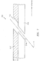
- FIG. 3A a schematic depiction of a nozzle 300a is shown.
- the nozzle 300a may include a substrate 304.
- the substrate 304 may include a metal, such as for example a nickel, steel, aluminum, etc.
- One or more coatings (represented by coating 310) may be applied/coupled to the substrate 304.
- the coatings 310 may include one or more materials, such as for example a ceramic material (e.g., yttria stabilized zirconia) or a metallic material (e.g., MCrAlY, where M is frequently at least one of iron, cobalt, or nickel, and X is an active element and stands for at least one of yttrium, silicon, a rare earth element, or hafnium).
- a ceramic material e.g., yttria stabilized zirconia
- a metallic material e.g., MCrAlY, where M is frequently at least one of iron, cobalt, or nickel, and X is an active element and stands for at least one of yttrium, silicon, a rare earth element, or hafnium.
- a first hole 316a may be formed through the substrate 304.
- a second hole 316b may be formed through the coating 310.
- the holes 316a and 316b may be arranged about an axis 'A', e.g., the holes 316a and 316b may be co-axial.
- the holes 316a and 316b may be used to cool the nozzle 300a.
- the holes 316a and 316b may provide a thin film of cooling air on an exterior/outer surface 310a of the coating 310.
- the holes 316a and 316b are shown in FIG. 3A as being oriented at an angle relative to the substrate 304 and the coating 310.
- the holes 316a and 316b are shown in FIG. 3A as being oriented at an angle of approximately forty-five degrees relative to the superimposed horizontal reference direction.
- a particular value for an angle (e.g., thirty degrees) that is used for the holes 316a and 316b may be based on one or more parameters of the nozzle 300a, such as for example a specification associated with the substrate 304 or the coating 310.
- a size or dimension of the holes 316a and 316b may be based on one or more parameters of the nozzle 300a. While the holes 316a and 316b are shown as being substantially cylindrical, other shapes/form-factors for the holes 316a and 316b may be used.
- the nozzle 300a shown in FIG. 3A may be indicative of an original equipment manufacture (OEM), and the holes 316a and 316b may be formed in the nozzle 300a following the application of the coating 310 to the substrate 304. During engine maintenance procedures, the nozzle 300a may be subject to further processing/reconditioning as described below.
- OEM original equipment manufacture
- the holes 316a and 316b may be formed in the nozzle 300a following the application of the coating 310 to the substrate 304.
- the nozzle 300a may be subject to further processing/reconditioning as described below.
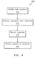
- a method 400 for processing/reconditioning a component is shown.
- the method 400 may be performed as part of an engine maintenance procedure.
- the method 400 is described below in conjunction with the nozzle(s) shown in FIGS. 3A-3D for ease in description and illustration.
- the method 400 may be adapted to accommodate other components (e.g., other nozzles). While the nozzles 300a-300d are described below as being separate nozzles (e.g., are shown with distinct reference characters in FIGS. 3A-3D ), one will appreciate that they may represent the same nozzle at different points/steps of processing/conditioning in accordance with the execution of the method 400.
- a location of one or more holes may be identified.
- a map/specification of a location of a hole may be consulted.
- the map/specification may be established during the original manufacture of the nozzle 300a and may be particular to the specific instance of the nozzle 300a.
- the location of a hole may be specified with respect to a serial number (or other part tracking identifier) of the nozzle 300a.
- the location of a hole may be specified on the basis of a make/model number of the nozzle 300a.
- the location of a hole may be based on an identification of one or more other features of the nozzle 300a, such as for example an external edge/surface of the nozzle 300a.
- a location of a hole may be determined based on one or more scans incorporating one or more sensors as would be known to one of skill in the art.
- U.S. patent number 7,329,832 provides examples of such scanning.
- one or more coatings 310 may be removed from the substrate 304.
- a toolset 340 may be applied to the nozzle 300a (e.g., the coating 310) of FIG. 3A to generate a substrate 304/nozzle 300b (see FIG. 3B ) that is substantially coat-free.
- the nozzle 300b is substantially similar to the nozzle 300a but does not include the coating 310.
- the toolset 340 may be operative on the basis of one or more techniques, such as for example use of a water-jet, sand-blasting, etc.
- the toolset 340 may be operated manually.
- the toolset may be operated on at least a partially automated basis. To the extent that the toolset 340 is automated, the toolset 340 may include a system similar to the system 500 described below in conjunction with FIG. 5 .
- the substrate 304/nozzle 300b of FIG. 3B may be (re)coated to include a coating 310' in forming a nozzle 300c (see FIG. 3C ).
- a thickness 'T' of the coating 310' may be substantially equal to a thickness 'T' of the coating 310.
- the coating performed in block 418 may substantially restore the coating 310' on the substrate 304 to the (original) thickness of the coating 310.
- a portion of the coating 310' in proximity to the hole 316a (as reflected by the portion inside the circle 322) may at least partially or completely block the hole 316a.
- a blocking of the hole 316a includes at least a partial or complete obstruction of the hole 316a that precludes a flow of a fluid (e.g., air) through both the substrate 304 and the coating 310'.
- a fluid e.g., air
- the flow interfering portion 322 of the coating 310' may be removed to generate a hole 316b' through the coating 310'.
- a nozzle 300d may be formed via the removal of the flow interfering portion 322 of the coating 310'.
- the removal of the flow interfering portion 322 may be facilitated by application of a toolset 350 to the flow interfering portion 322 as shown in FIG. 3C .
- the holes 316a and 316b' may be arranged about the axis 'A' in a manner similar to the arrangement of the holes 316a and 316b about the axis 'A' shown in FIG. 3A .
- the toolset 350 may correspond to the toolset 340 shown in FIG. 3A .
- the toolset 350 may include a laser 360 that may be used to remove the flow interfering portion 322.
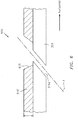
- a counterbore may be formed in the coating 310', the counterbore coinciding with the hole 316b'.
- the depth/thickness of the counterbore may be substantially equal to the thickness 'T' of the coating 310'.
- a dimension of the counterbore (illustratively shown in FIG.
- 3D as a width 'W' being measured at the interface between the substrate 304 and the coating 310' from an edge 328 of the substrate 304 where the substrate 304 and the hole 316a meet) may have a value within a range of 50-100% of a dimension (e.g., a (mean) diameter 'D') of the hole 316a.
- the substrate 304 may be free of coating in a region of the substrate 304 that is proximate the hole 316a and adjacent to the edge 328 over a span coinciding with the width 'W'. Stated slightly differently, a clearance may be established from the edge 328 of the substrate 304 to the coating 310' equal to the value of the width 'W'.
- width 'W' While specified in terms of width 'W', other dimensions (e.g., a diameter) of the counterbore may be specified to reflect/represent an enlargement in the coating 310' relative to a dimension (e.g., the diameter 'D') of the hole 316a.
- the width 'W' may be uniform/symmetrical about the hole 316a. In some embodiments, the width 'W' may be non-uniform/asymmetrical about the hole 316a; for example, multiple values for the width 'W' may be used in a given embodiment.
- the inclusion of the counterbore in the coating 310' may be provided to account for component and/or process tolerances.
- the counterbore may be provided to account for differences in a location of the hole 316a on a first instance of the nozzle 300a relative to a location of that same counterpart hole 316a on a second instance of the nozzle 300a.
- the particular value for a dimension (e.g., width 'W') that is used in a given application may be determined based on a size that is considered to be acceptable to the function/purpose of the coating 310' in the first instance.
- one or more thresholds may be established based on a thermal conductivity or thermal loss associated with the substrate 304 and/or the coating 310/310'.
- the technique that is applied may leave the substrate 304 substantially undisturbed.
- one or more of the parameters of the toolset 350 may be controlled/regulated so as to only remove the flow interfering portion 322 of the coating 310'.
- parameters of the laser 360 that may be regulated include: the total number of laser pulses during drilling, laser power, pulse width, or spot size (potentially as a function of a given power).
- Blocks of the method 400 may execute in an order or sequence that is different from what is shown in FIG. 4 .
- block 412 may execute prior to block 406, as doing so may provide a greater ability to identify the hole(s) 316a in the first instance without the obstruction presented by, e.g., the coating(s) 310.
- One or more of the blocks (or one or more portions thereof) of the method 400 may be optional in some embodiments. In some embodiments, additional blocks not shown in FIG. 4 may be included.
- a counterbore in the coating 310' is merely one example of a type of hole/bore that may be created concurrent with or following the removal of the flow interfering portion 322.
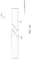
- a hole/bore may be formed, wherein the hole/bore includes a tapered sidewall 610.
- FIG. 7 illustrates yet another exemplary embodiment of a nozzle 700 following a removal of the flow interfering portion 322.
- a sidewall 710 may be formed in the coating 310' that may be substantially parallel to the axis A, such that a counterbore is included as part of the nozzle 700.
- the bore may be larger in dimension than the dimension(s) of the hole 316a.
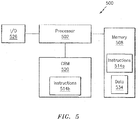
- FIG. 5 a computing system 500 that may be used in some embodiments is shown.
- the system 500 may be used to perform one or more portions of the method 400 of FIG. 4 described above. At least a part of the system 500 may be included in the toolset 350 of FIG. 3C .
- the system 500 may be used to control/regulate operation of the laser 360 in some embodiments.
- the system 500 may include a processor 502 and a memory 508.
- the memory 508 may store instructions (e.g., instructions 514a) that, when executed by the processor 502, may cause the system 500 to perform one or more methodological acts, such as one or more of the acts described herein. At least a portion of the instructions (e.g., instructions 514b) may be stored on a computer-readable medium (CRM) 520, such as for example a non-transitory CRM.
- CRM computer-readable medium
- the instructions 514b of the CRM 520 may be used as an alternative to, or in addition to, the use of the instructions 514a of the memory 508.
- One or both of the memory 508 and the CRM 520, taken individually or collectively, may be referred to as a storage device. Much like the CRM 520, the storage device may be non-transitory in nature.
- the system 500 may include one or more input/output (I/O) devices 526.
- the I/O devices 526 may provide an interface between the system 500 and one or more other components or devices.
- the I/O devices 526 may include one or more of a graphical user interface (GUI), a display screen, a touchscreen, a keyboard, a mouse, a joystick, a pushbutton, a microphone, a speaker, a transceiver, a laser, a drill, etc.
- GUI graphical user interface
- the I/O devices 526 may be used to output data in one or more formats (e.g., a visual or audio rendering).
- the memory 508 may store data 534.
- the data 534 may include an identification of one or more of: a type, material, or thickness of coating that is used (see, e.g., FIG. 3A - coating 310; FIG. 3C - coating 310'), a type or material of a substrate that is used (see, e.g., FIG. 3A - substrate 304), a location of one or more holes (see, e.g., FIG. 3A - hole 316a), a type of laser that is used (see, e.g., FIG. 3C - laser 360), or an identification of the specific laser 360 that is used.
- An identification of the specific laser 360 that is used may allow for a removal of the flow interfering portion 322 of the coating 310' to take into account variations between different instances of the laser 360 (e.g., variations in parameters associated with the laser 360).
- Portions of the data 534 may be remotely located and accessible to the system 500 via an extranet or the internet of things.
- the system 500 is illustrative. One skilled in the art will appreciate, based on a review of this disclosure, that the implementation of the system 500 may be achieved via the use of hardware, software, firmware, or any combination thereof.
- aspects of the disclosure may be applied to other types of components (e.g., other components of an engine).
- aspects of the disclosure may be applied to vanes, blades, flaps, cases, liners, etc.
- aspects of the disclosure may be used to remove/clear an obstruction from one or more cooling holes.
- Such an obstruction may include, for example, a coating that is applied during a recoating procedure.
- the cooling holes may be cleared without having an appreciable impact to a substrate of a component.
- a cooling hole size and orientation may be controlled/regulated to conform to a particular specification.
Applications Claiming Priority (1)
| Application Number | Priority Date | Filing Date | Title |
|---|---|---|---|
| US15/670,330 US11752573B2 (en) | 2017-08-07 | 2017-08-07 | Laser clearance of coating |
Publications (2)
| Publication Number | Publication Date |
|---|---|
| EP3441569A1 true EP3441569A1 (de) | 2019-02-13 |
| EP3441569B1 EP3441569B1 (de) | 2023-09-27 |
Family
ID=63165302
Family Applications (1)
| Application Number | Title | Priority Date | Filing Date |
|---|---|---|---|
| EP18187595.6A Active EP3441569B1 (de) | 2017-08-07 | 2018-08-06 | Verfahren zum herstellen eines komponentes, düsenauslass und anordnung zur laserbeseitigung einer beschichtung |
Country Status (2)
| Country | Link |
|---|---|
| US (1) | US11752573B2 (de) |
| EP (1) | EP3441569B1 (de) |
Families Citing this family (1)
| Publication number | Priority date | Publication date | Assignee | Title |
|---|---|---|---|---|
| US11407067B2 (en) * | 2018-06-29 | 2022-08-09 | Pratt & Whitney Canada Corp. | Method for repairing a part |
Citations (7)
| Publication number | Priority date | Publication date | Assignee | Title |
|---|---|---|---|---|
| EP1043480A2 (de) * | 1999-04-05 | 2000-10-11 | General Electric Company | Filmkühlung von heissen Wänden |
| WO2006106061A1 (de) * | 2005-04-07 | 2006-10-12 | Alstom Technology Ltd | Verfahren zum reparieren oder erneuern von kühllöchern einer beschichteten komponente einer gasturbine |
| US7329832B2 (en) | 2003-08-27 | 2008-02-12 | Alstom Technology Ltd. | Automated adaptive machining of obstructed passages |
| EP2301730A1 (de) * | 2009-09-25 | 2011-03-30 | United Technologies Corporation | Lochbohrung in der Nähe einer Rückwand |
| EP2386823A1 (de) * | 2010-05-12 | 2011-11-16 | Siemens Aktiengesellschaft | Oberflächenanalyse zur Detektierung verschlossener Löcher und Verfahren zur Wiedereröffnung |
| WO2014120152A1 (en) * | 2013-01-30 | 2014-08-07 | United Technologies Corporation | Coating process for gas turbine engine component with cooling holes |
| EP3059040A1 (de) * | 2015-02-20 | 2016-08-24 | General Electric Company | Komponentenreparatur mittels begrenztem laserbohren |
Family Cites Families (7)
| Publication number | Priority date | Publication date | Assignee | Title |
|---|---|---|---|---|
| US6172331B1 (en) | 1997-09-17 | 2001-01-09 | General Electric Company | Method and apparatus for laser drilling |
| US8237082B2 (en) | 2004-09-02 | 2012-08-07 | Siemens Aktiengesellschaft | Method for producing a hole |
| EP1844892A1 (de) * | 2006-04-13 | 2007-10-17 | ALSTOM Technology Ltd | Verfahren zur Laserentfernung von Beschichtenmaterialen in Kühlenlöchern eines Turbinenbauteiles |
| US20090142548A1 (en) * | 2007-10-18 | 2009-06-04 | David Bruce Patterson | Air cooled gas turbine components and methods of manufacturing and repairing the same |
| US20120167389A1 (en) * | 2011-01-04 | 2012-07-05 | General Electric Company | Method for providing a film cooled article |
| PL2604378T3 (pl) | 2011-12-15 | 2015-08-31 | Siemens Ag | Ponowne otwieranie otworów powietrza chłodzącego za pomocą lasera nanosekundowego w zakresie mikrosekundowym |
| US9284844B2 (en) * | 2012-02-15 | 2016-03-15 | United Technologies Corporation | Gas turbine engine component with cusped cooling hole |
-
2017
- 2017-08-07 US US15/670,330 patent/US11752573B2/en active Active
-
2018
- 2018-08-06 EP EP18187595.6A patent/EP3441569B1/de active Active
Patent Citations (7)
| Publication number | Priority date | Publication date | Assignee | Title |
|---|---|---|---|---|
| EP1043480A2 (de) * | 1999-04-05 | 2000-10-11 | General Electric Company | Filmkühlung von heissen Wänden |
| US7329832B2 (en) | 2003-08-27 | 2008-02-12 | Alstom Technology Ltd. | Automated adaptive machining of obstructed passages |
| WO2006106061A1 (de) * | 2005-04-07 | 2006-10-12 | Alstom Technology Ltd | Verfahren zum reparieren oder erneuern von kühllöchern einer beschichteten komponente einer gasturbine |
| EP2301730A1 (de) * | 2009-09-25 | 2011-03-30 | United Technologies Corporation | Lochbohrung in der Nähe einer Rückwand |
| EP2386823A1 (de) * | 2010-05-12 | 2011-11-16 | Siemens Aktiengesellschaft | Oberflächenanalyse zur Detektierung verschlossener Löcher und Verfahren zur Wiedereröffnung |
| WO2014120152A1 (en) * | 2013-01-30 | 2014-08-07 | United Technologies Corporation | Coating process for gas turbine engine component with cooling holes |
| EP3059040A1 (de) * | 2015-02-20 | 2016-08-24 | General Electric Company | Komponentenreparatur mittels begrenztem laserbohren |
Also Published As
| Publication number | Publication date |
|---|---|
| EP3441569B1 (de) | 2023-09-27 |
| US11752573B2 (en) | 2023-09-12 |
| US20190039177A1 (en) | 2019-02-07 |
Similar Documents
| Publication | Publication Date | Title |
|---|---|---|
| EP3467256B1 (de) | Mehrstufige beseitigung einer beschichtung | |
| JP4802192B2 (ja) | ガスタービンジェットエンジンにおけるタービンケースの補強 | |
| US7816625B2 (en) | Method for the production of a hole and device | |
| US9879544B2 (en) | Turbine rotor blades with improved tip portion cooling holes | |
| EP3070406A1 (de) | Motorbauteil | |
| EP3061911A1 (de) | Motorbauteil | |
| US10030524B2 (en) | Machined film holes | |
| US20200025014A1 (en) | Seal coating | |
| JP2017089639A (ja) | フィルム孔を有するガスタービンエンジン構成要素 | |
| US10458254B2 (en) | Abradable coating composition for compressor blade and methods for forming the same | |
| US11143048B2 (en) | Labyrinth seal with variable tooth heights | |
| EP3441569B1 (de) | Verfahren zum herstellen eines komponentes, düsenauslass und anordnung zur laserbeseitigung einer beschichtung | |
| US20150198048A1 (en) | Method for producing a stator blade and stator blade | |
| EP2022597A1 (de) | Verfahren zum Reparieren der Messerschneidendichtungen von Gasturbinenmotoren | |
| US20190128144A1 (en) | Repair of components using additive manufacturing with in-situ cold working | |
| Von der Bank et al. | Compressors for ultra-high-pressure-ratio aero-engines | |
| Mishra et al. | Investigation of LP turbine blade failure in a low bypass turbofan engine | |
| Moreau | Theoretical acoustic benefit of high bypass ratio and variable-area nozzle in turbofan engines | |
| EP2984472A2 (de) | Verfahren zur erkennung einer beschädigten komponente | |
| US20190010811A1 (en) | Method for manufacture of high temperature cylindrical component for a gas turbine engine | |
| Kappis et al. | Detailed Compressor Degradation Effect Modeling for Single Blade Rows While Assessing Its Local and Overall Consequences | |
| US20230070114A1 (en) | Multi-step method for machining blind ope1ning in ceramic component | |
| US20220341019A1 (en) | Case flowpath repair system and method | |
| EP4134518A2 (de) | Herstellung von kühlungsöffnungen in einer komponente eines turbinentriebwerks | |
| EP4134522A2 (de) | Energiestrahlpositionierung bei der bildung einer kühlöffnung |
Legal Events
| Date | Code | Title | Description |
|---|---|---|---|
| PUAI | Public reference made under article 153(3) epc to a published international application that has entered the european phase |
Free format text: ORIGINAL CODE: 0009012 |
|
| STAA | Information on the status of an ep patent application or granted ep patent |
Free format text: STATUS: THE APPLICATION HAS BEEN PUBLISHED |
|
| AK | Designated contracting states |
Kind code of ref document: A1 Designated state(s): AL AT BE BG CH CY CZ DE DK EE ES FI FR GB GR HR HU IE IS IT LI LT LU LV MC MK MT NL NO PL PT RO RS SE SI SK SM TR |
|
| AX | Request for extension of the european patent |
Extension state: BA ME |
|
| STAA | Information on the status of an ep patent application or granted ep patent |
Free format text: STATUS: REQUEST FOR EXAMINATION WAS MADE |
|
| 17P | Request for examination filed |
Effective date: 20190813 |
|
| RBV | Designated contracting states (corrected) |
Designated state(s): AL AT BE BG CH CY CZ DE DK EE ES FI FR GB GR HR HU IE IS IT LI LT LU LV MC MK MT NL NO PL PT RO RS SE SI SK SM TR |
|
| STAA | Information on the status of an ep patent application or granted ep patent |
Free format text: STATUS: EXAMINATION IS IN PROGRESS |
|
| 17Q | First examination report despatched |
Effective date: 20210201 |
|
| RAP1 | Party data changed (applicant data changed or rights of an application transferred) |
Owner name: RAYTHEON TECHNOLOGIES CORPORATION |
|
| STAA | Information on the status of an ep patent application or granted ep patent |
Free format text: STATUS: EXAMINATION IS IN PROGRESS |
|
| GRAP | Despatch of communication of intention to grant a patent |
Free format text: ORIGINAL CODE: EPIDOSNIGR1 |
|
| STAA | Information on the status of an ep patent application or granted ep patent |
Free format text: STATUS: GRANT OF PATENT IS INTENDED |
|
| INTG | Intention to grant announced |
Effective date: 20230303 |
|
| GRAS | Grant fee paid |
Free format text: ORIGINAL CODE: EPIDOSNIGR3 |
|
| GRAA | (expected) grant |
Free format text: ORIGINAL CODE: 0009210 |
|
| STAA | Information on the status of an ep patent application or granted ep patent |
Free format text: STATUS: THE PATENT HAS BEEN GRANTED |
|
| AK | Designated contracting states |
Kind code of ref document: B1 Designated state(s): AL AT BE BG CH CY CZ DE DK EE ES FI FR GB GR HR HU IE IS IT LI LT LU LV MC MK MT NL NO PL PT RO RS SE SI SK SM TR |
|
| REG | Reference to a national code |
Ref country code: GB Ref legal event code: FG4D |
|
| REG | Reference to a national code |
Ref country code: CH Ref legal event code: EP |
|
| REG | Reference to a national code |
Ref country code: DE Ref legal event code: R096 Ref document number: 602018058165 Country of ref document: DE |
|
| REG | Reference to a national code |
Ref country code: IE Ref legal event code: FG4D |
|
| RAP4 | Party data changed (patent owner data changed or rights of a patent transferred) |
Owner name: RTX CORPORATION |
|
| REG | Reference to a national code |
Ref country code: LT Ref legal event code: MG9D |
|
| PG25 | Lapsed in a contracting state [announced via postgrant information from national office to epo] |
Ref country code: GR Free format text: LAPSE BECAUSE OF FAILURE TO SUBMIT A TRANSLATION OF THE DESCRIPTION OR TO PAY THE FEE WITHIN THE PRESCRIBED TIME-LIMIT Effective date: 20231228 |
|
| PG25 | Lapsed in a contracting state [announced via postgrant information from national office to epo] |
Ref country code: SE Free format text: LAPSE BECAUSE OF FAILURE TO SUBMIT A TRANSLATION OF THE DESCRIPTION OR TO PAY THE FEE WITHIN THE PRESCRIBED TIME-LIMIT Effective date: 20230927 Ref country code: RS Free format text: LAPSE BECAUSE OF FAILURE TO SUBMIT A TRANSLATION OF THE DESCRIPTION OR TO PAY THE FEE WITHIN THE PRESCRIBED TIME-LIMIT Effective date: 20230927 Ref country code: NO Free format text: LAPSE BECAUSE OF FAILURE TO SUBMIT A TRANSLATION OF THE DESCRIPTION OR TO PAY THE FEE WITHIN THE PRESCRIBED TIME-LIMIT Effective date: 20231227 Ref country code: LV Free format text: LAPSE BECAUSE OF FAILURE TO SUBMIT A TRANSLATION OF THE DESCRIPTION OR TO PAY THE FEE WITHIN THE PRESCRIBED TIME-LIMIT Effective date: 20230927 Ref country code: LT Free format text: LAPSE BECAUSE OF FAILURE TO SUBMIT A TRANSLATION OF THE DESCRIPTION OR TO PAY THE FEE WITHIN THE PRESCRIBED TIME-LIMIT Effective date: 20230927 Ref country code: HR Free format text: LAPSE BECAUSE OF FAILURE TO SUBMIT A TRANSLATION OF THE DESCRIPTION OR TO PAY THE FEE WITHIN THE PRESCRIBED TIME-LIMIT Effective date: 20230927 Ref country code: GR Free format text: LAPSE BECAUSE OF FAILURE TO SUBMIT A TRANSLATION OF THE DESCRIPTION OR TO PAY THE FEE WITHIN THE PRESCRIBED TIME-LIMIT Effective date: 20231228 Ref country code: FI Free format text: LAPSE BECAUSE OF FAILURE TO SUBMIT A TRANSLATION OF THE DESCRIPTION OR TO PAY THE FEE WITHIN THE PRESCRIBED TIME-LIMIT Effective date: 20230927 |
|
| REG | Reference to a national code |
Ref country code: NL Ref legal event code: MP Effective date: 20230927 |
|
| REG | Reference to a national code |
Ref country code: AT Ref legal event code: MK05 Ref document number: 1615622 Country of ref document: AT Kind code of ref document: T Effective date: 20230927 |
|
| PG25 | Lapsed in a contracting state [announced via postgrant information from national office to epo] |
Ref country code: NL Free format text: LAPSE BECAUSE OF FAILURE TO SUBMIT A TRANSLATION OF THE DESCRIPTION OR TO PAY THE FEE WITHIN THE PRESCRIBED TIME-LIMIT Effective date: 20230927 |
|
| PG25 | Lapsed in a contracting state [announced via postgrant information from national office to epo] |
Ref country code: IS Free format text: LAPSE BECAUSE OF FAILURE TO SUBMIT A TRANSLATION OF THE DESCRIPTION OR TO PAY THE FEE WITHIN THE PRESCRIBED TIME-LIMIT Effective date: 20240127 |