EP3441558B2 - Geschützte ringkanaldurchflussanordnung für ein unterwasserkomplettierungssystem - Google Patents
Geschützte ringkanaldurchflussanordnung für ein unterwasserkomplettierungssystem Download PDFInfo
- Publication number
- EP3441558B2 EP3441558B2 EP18164404.8A EP18164404A EP3441558B2 EP 3441558 B2 EP3441558 B2 EP 3441558B2 EP 18164404 A EP18164404 A EP 18164404A EP 3441558 B2 EP3441558 B2 EP 3441558B2
- Authority
- EP
- European Patent Office
- Prior art keywords
- annulus
- subsea
- tubing
- tubing hanger
- flow passage
- Prior art date
- Legal status (The legal status is an assumption and is not a legal conclusion. Google has not performed a legal analysis and makes no representation as to the accuracy of the status listed.)
- Active
Links
Images

Classifications
-
- E—FIXED CONSTRUCTIONS
- E21—EARTH OR ROCK DRILLING; MINING
- E21B—EARTH OR ROCK DRILLING; OBTAINING OIL, GAS, WATER, SOLUBLE OR MELTABLE MATERIALS OR A SLURRY OF MINERALS FROM WELLS
- E21B33/00—Sealing or packing boreholes or wells
- E21B33/02—Surface sealing or packing
- E21B33/03—Well heads; Setting-up thereof
- E21B33/035—Well heads; Setting-up thereof specially adapted for underwater installations
-
- E—FIXED CONSTRUCTIONS
- E21—EARTH OR ROCK DRILLING; MINING
- E21B—EARTH OR ROCK DRILLING; OBTAINING OIL, GAS, WATER, SOLUBLE OR MELTABLE MATERIALS OR A SLURRY OF MINERALS FROM WELLS
- E21B33/00—Sealing or packing boreholes or wells
- E21B33/02—Surface sealing or packing
- E21B33/03—Well heads; Setting-up thereof
- E21B33/04—Casing heads; Suspending casings or tubings in well heads
- E21B33/0407—Casing heads; Suspending casings or tubings in well heads with a suspended electrical cable
-
- E—FIXED CONSTRUCTIONS
- E21—EARTH OR ROCK DRILLING; MINING
- E21B—EARTH OR ROCK DRILLING; OBTAINING OIL, GAS, WATER, SOLUBLE OR MELTABLE MATERIALS OR A SLURRY OF MINERALS FROM WELLS
- E21B33/00—Sealing or packing boreholes or wells
- E21B33/02—Surface sealing or packing
- E21B33/03—Well heads; Setting-up thereof
- E21B33/04—Casing heads; Suspending casings or tubings in well heads
- E21B33/043—Casing heads; Suspending casings or tubings in well heads specially adapted for underwater well heads
-
- E—FIXED CONSTRUCTIONS
- E21—EARTH OR ROCK DRILLING; MINING
- E21B—EARTH OR ROCK DRILLING; OBTAINING OIL, GAS, WATER, SOLUBLE OR MELTABLE MATERIALS OR A SLURRY OF MINERALS FROM WELLS
- E21B33/00—Sealing or packing boreholes or wells
- E21B33/02—Surface sealing or packing
- E21B33/03—Well heads; Setting-up thereof
- E21B33/068—Well heads; Setting-up thereof having provision for introducing objects or fluids into, or removing objects from, wells
- E21B33/076—Well heads; Setting-up thereof having provision for introducing objects or fluids into, or removing objects from, wells specially adapted for underwater installations
-
- E—FIXED CONSTRUCTIONS
- E21—EARTH OR ROCK DRILLING; MINING
- E21B—EARTH OR ROCK DRILLING; OBTAINING OIL, GAS, WATER, SOLUBLE OR MELTABLE MATERIALS OR A SLURRY OF MINERALS FROM WELLS
- E21B33/00—Sealing or packing boreholes or wells
- E21B33/02—Surface sealing or packing
- E21B33/03—Well heads; Setting-up thereof
- E21B33/04—Casing heads; Suspending casings or tubings in well heads
Definitions
- Hydrocarbon fluids such as oil and natural gas are obtained from a subterranean geologic formation, referred to as a reservoir, by drilling a well that penetrates the hydrocarbon-bearing geologic formation.
- the well is drilled at a subsea location and the flow of fluids may be handled by several different types of equipment.
- subsea equipment may comprise subsea completion systems which may include or work in cooperation with subsea installations mounted over a wellhead.
- the subsea installations may comprise various components, e.g. tubing hangers and subsea trees, and may incorporate fluid flow paths, e.g. a production flow path and an annulus flow path.
- the system according to the invention protect potentially susceptible components from unwanted exposure to well fluids or other fluids in a monobore subsea installation.
- the subsea installation may comprise various components, e.g. a tubing hanger and a subsea tree which form a plenum region therebetween.
- An annulus stab (or stabs) is positioned to extend between the tubing hanger and the subsea tree so as to provide an isolated annulus flow path within the annulus stab and through the plenum region.
- the isolated annulus flow path also is defined, in part, by a passageway extending longitudinally through the tubing hanger until exiting through a side of the tubing hanger.
- the present disclosure generally relates to a system and methodology which are utilized in protecting potentially susceptible components from unwanted exposure to well fluids or other fluids in a monobore subsea installation.
- the subsea installation may comprise various components which interface with each other, e.g. a tubing hanger and a subsea tree which form a plenum region therebetween.
- the tubing hanger also may form an interface with other components such as a tubing hanger running tool.
- a production path and an annulus path are routed through the subsea installation which may have a subsea tree with a monobore configuration.
- a vertical monobore subsea tree has a central production bore through the subsea tree rather than a production bore at a radially offset position as found in dual bore subsea trees.
- a vertical monobore subsea tree configuration may be configured with a central production bore which provides a production flow path.
- the annulus flow path may be provided by two or more smaller annulus stabs selected to achieve a desired flow area.
- the annulus stabs may be located on the same centerline and bolt circle as hydraulic and electric couplers in a given vertical monobore subsea tree. This approach may be used to provide better deflection characteristics throughout the body of the subsea tree when high pressure is applied to the production bore and/or production stabs.
- the subsea well system 20 may comprise a subsea installation 22, e.g. a monobore subsea installation.
- the subsea installation 22 may have a variety of components, such as a subsea tree 24, e.g. a vertical monobore subsea tree, mounted on a tubing head spool 26 positioned over a wellhead 28 at a subsea surface/mudline 30.
- the wellhead 28 may be positioned over a well 32 in which production tubing 34 is suspended from a tubing hanger 36 located at tubing head spool 26.
- the production tubing 34 and a well casing 38 establish flow passages, such as a subsurface production flow passage 40 and an annulus flow passage 42.
- the production flow passage 40 and the annulus flow passage 42 are continued up through tubing head spool 26, tubing hanger 36, and subsea tree 24 via a subsea installation production flow passage 44 and a subsea installation annulus flow passage 46, respectively.
- the flow passages may be split into a plurality of passages.
- the annulus flow passage 46 may comprise a plurality of flow passages arranged around a centrally located production passage 44.
- passages 44, 46 provide desired flow paths and flow capacities through the tubing head spool 26, tubing hanger 36, and subsea tree 24. Fluid flow along production flow passage 44 and annulus flow passage 46 may be controlled by production valve(s) 48 and annulus valve(s) 50, respectively.
- valves 48, 50 may comprise production gate valves and annulus gate valves.
- the subsea well system 20 also comprises a tree cap 52 which may be releasably deployed into engagement with the subsea tree 24.
- the annulus flow passage 42 is between the production tubing 34 and well casing 38 and is concentrically located about the production flow passage 40 within production tubing 34.
- Production fluid is able to flow up through production tubing 34 and continue through the subsea installation 22 along installation production flow passage 44 as controlled via valves 48.
- the installation annulus flow passage 46 is in communication with the annulus between production tubing 34 and well casing 38 to allow annular flow as controlled via valves 50.
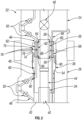
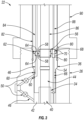
- FIG. 2 an embodiment of the subsea installation 22 is illustrated in which subsea tree 24 is mounted on tubing head spool 26 and tubing hanger 36 is suspended in the tubing head spool 26 via an abutment 54.
- the installation production flow passage 44 extends generally along a center line of the tubing head spool 26, tubing hanger 36, and subsea tree 24 (a monobore configuration). Fluid communication along flow passage 44 between tubing hanger 36 and subsea tree 24 may be enabled via a production stab 56.
- the production stab 56 may be sealed with respect to inside surfaces of the tubing hanger 36 and the subsea tree 24 via appropriate seals 58, e.g.
- the production stab 56 also facilitates coupling and decoupling of the subsea tree 24 with respect to the tubing hanger 36 when the subsea tree 24 is mounted on tubing head spool 26 or removed from tubing head spool 26, respectively.
- the installation annulus flow passage 46 is placed in communication with the annulus between production tubing 34 and well casing 38 at tubing head spool 26.
- the flow passage 46 is routed along the tubing head spool 26 and through an annulus valve or valves 50, e.g. a pair of annulus valves 50, before entering tubing hanger 36 through, for example, a side of the tubing hanger 36.
- Appropriate seals 60 e.g. O-ring seals or other suitable seals, may be positioned between an exterior surface of tubing hanger 36 and an interior surface of tubing head spool 26 to ensure a sealed annular flow passage between tubing head spool 26 and tubing hanger 36.
- Fluid communication along flow passage 46 between tubing hanger 36 and subsea tree 24 may be enabled via an annulus stab 62.
- the annulus stab 62 may be sealed with respect to inside surfaces of the tubing hanger 36 and the subsea tree 24 via appropriate seals 64, e.g. O-ring seals or other suitable seals.
- the annulus stab 62 further facilitates coupling and decoupling of the subsea tree 24 with respect to the tubing hanger 36 when the subsea tree 24 is mounted on tubing head spool 26 or removed from tubing head spool 26, respectively.
- the stabs 56, 62 may be in the form of tubing sections or other suitable structures which extend between the sections of the annulus flow passage 46 in the tubing hanger 36 and in the subsea tree 24.
- the portion of annulus flow passage 46 in subsea tree 24 is routed through the subsea tree 24 from a bottom to a top of the subsea tree 24.
- the installation annulus flow passage 46 may comprise a plurality of passages.
- the plurality of passages forming flow passage 46 may be disposed about the production flow passage 44.
- a plurality of corresponding annulus stabs 62 e.g. two annulus stabs, may be positioned along the plurality of passages, e.g. two passages, forming the annulus flow passage 46 between the tubing hanger 36 and subsea tree 24.
- the flow passage 46 is routed through subsea tree 24 and through an annulus valve or valves 50, e.g. a pair of annulus valves 50.
- appropriate arrangements of production valves 48 also may be located in subsea tree 24.
- one or more control lines 66 also may be routed through subsea installation 22.
- the control line(s) 66 may be routed through components of the subsea installation such as the subsea tree 24, tubing hanger 36, and tubing head spool 26.
- Appropriate couplers 68 may be used for joining sections of each control line 66 to facilitate coupling and decoupling of adjacent subsea installation components.
- couplers 68 comprises a pair of mating connectors 70, e.g. wet mate connectors, which are passively coupled or decoupled when the subsea tree 24 is mounted on tubing head spool 26 or removed from tubing head spool 26, respectively.
- stabs such as production stab 56 and annulus stabs 62 provides a protected flow path for well fluids through a plenum region 72.
- Various components 74 e.g. sensors, electronics, seals, and other components susceptible to the deleterious effects well fluid, may be positioned in or along the plenum region 72.
- the stabs, e.g. stabs 56, 62, provide isolation and protection for these components 74 by containing both the production flow and annulus flow of fluids along the interior of subsea installation 22.
- the components of subsea tree 24, tubing head spool 26, tubing hanger 36, and/or other components of subsea installation 22 may vary.
- the subsea tree 22 may comprise various components and arrangements of production passages and annulus passages. In a vertical monobore configuration, various arrangements and numbers of annulus passages may be positioned around a monobore production passage.
- various types of stabs 56, 62 and couplers 68 may be used to facilitate relatively easy coupling and decoupling of the subsea installation components.
- the tubing hanger running tool 82 may be constructed in various configurations with a variety of components selected according to the parameters of a given subsea operation.
- Different embodiments of the subsea installation 22 may comprise plenum regions having gallery areas 76 of many sizes and configurations.
- the gallery areas 76 may be specifically constructed to facilitate containment of or interaction with many types of components 74. Because the components 74 are protected from the annulus flow of well fluids, additional types of components 74 may be exposed to the gallery area 76.
- different types of materials and protective features e.g. less expensive materials and protective features, may be used in constructing components 74 due to the isolation of well fluids along the enclosed installation annulus flow passage 46.
Landscapes
- Life Sciences & Earth Sciences (AREA)
- Engineering & Computer Science (AREA)
- Geology (AREA)
- Mining & Mineral Resources (AREA)
- Physics & Mathematics (AREA)
- Environmental & Geological Engineering (AREA)
- Fluid Mechanics (AREA)
- General Life Sciences & Earth Sciences (AREA)
- Geochemistry & Mineralogy (AREA)
- Earth Drilling (AREA)
Claims (10)
- System zur Verwendung in einer Unterwasserbohranwendung (20), umfassend:
eine Monobore-Unterwasserinstallation (22), aufweisend:eine Rohrkopfspule (26), die über einem Bohrkopf (28) angeordnet ist;einen Rohrhänger (36), der mit der Rohrkopfspule (26) in Eingriff steht;einen Unterwasserbaum (24), der über dem Rohrhänger (36) mit der Rohrkopfspule (26) gekoppelt ist und einen Plenumbereich (72) zwischen dem Rohrhänger (36) und dem Unterwasserbaum (24) bildet;dadurch gekennzeichnet, dass:
der Plenumbereich einen Galeriebereich (76) aufweist, der im Plenumbereich durch mindestens einen Ringraumstab (62) gebildet wird, der sich zwischen dem Rohrhänger (36) und dem Unterwasserbaum (24) erstreckt, der einen isolierten Pfad innerhalb des mindestens einen Ringraumstabs (62) und durch den Plenumbereich bereitstellt, wobei der Galeriebereich vor der Einwirkung der Ringraumströmung der Bohrflüssigkeiten geschützt ist, wobei der Plenumbereich Komponenten (74) umfasst, die im oder entlang des Plenumbereichs (72) positioniert sind, wobei die Komponenten (74) durch den mindestens einen Ringraumstab (62) vor der Ringraumströmung der Bohrflüssigkeiten geschützt sind, wobei der isolierte Pfad außerdem durch den Rohrhänger (36) geführt ist, bis er durch eine Seite des Rohrhängers (36) zur Rohrkopfspule (26) austritt, um einen Ringraumströmungspfad (46) entlang der Monobore-Unterwasserinstallation (22) aufzunehmen. - System nach Anspruch 1, wobei die Komponenten (74) Sensoren, Elektronik, Dichtungen und/oder andere Komponenten umfassen, die den schädlichen Auswirkungen von Bohrflüssigkeiten ausgesetzt sind.
- System nach Anspruch 1, wobei der mindestens eine Ringraumstab (62) mindestens ein Rohr umfasst, das sich zwischen einem Rohrhänger-Ringraumströmungskanal (46) im Rohrhänger (36) und einem Unterwasserbaum-Ringraumströmungskanal (46) im Unterwasserbaum (24) erstreckt.
- System nach Anspruch 1, wobei der mindestens eine Ringraumstab (62) eine Vielzahl von Ringraumstäben (62) zum Leiten einer Strömung entlang des isolierten Pfads (46) umfasst.
- System nach Anspruch 1, ferner umfassend einen Produktionsstab (56), der entlang einer Monobohrung (Einlochbohrung) der Monobore-Unterwasserinstallation (22) zwischen dem Rohrhänger (36) und dem Unterwasserbaum (24) angeordnet ist.
- System nach Anspruch 3, wobei der Unterwasserbaum-Ringraumströmungskanal (46) von einer Unterseite des Unterwasserbaums (24) zu einer Oberseite des Unterwasserbaums (24) durch den Unterwasserbaum (24) geführt ist.
- System nach Anspruch 3, wobei der Rohrhänger-Ringraumströmungskanal (46) in Längsrichtung durch eine Wand des Rohrhängers (36) geführt ist, bis er radial nach außen zur Seite des Rohrhängers (36) hin abbiegt und in einen abgedichteten Bereich gelangt, der in Verbindung mit einem entsprechenden Ringraumströmungskanal (46) in der Rohrkopfspule (26) steht.
- System nach Anspruch 7, wobei der entsprechende Ringraumströmungskanal (46) mit einem Ringraum (42) zwischen einem Bohrlochrohr (34) und einer Verrohrung (38) in Verbindung steht, die sich bis unter den Rohrhänger (36) erstreckt, um einen gesamten Ringströmungskanal (46) durch die Monobore-Unterwasserinstallation (22) zu bilden.
- System nach Anspruch 8, ferner umfassend eine Vielzahl von Ventilen (50), die entlang des gesamten Ringraumströmungskanals (46) angeordnet sind.
- System nach Anspruch 9, wobei mindestens zwei Ventile (50) der Vielzahl von Ventilen (50) entlang des entsprechenden Ringraumströmungskanals (46) durch die Rohrkopfspule (26) angeordnet sind.
Applications Claiming Priority (1)
| Application Number | Priority Date | Filing Date | Title |
|---|---|---|---|
| US15/470,099 US9945202B1 (en) | 2017-03-27 | 2017-03-27 | Protected annulus flow arrangement for subsea completion system |
Publications (4)
| Publication Number | Publication Date |
|---|---|
| EP3441558A2 EP3441558A2 (de) | 2019-02-13 |
| EP3441558A3 EP3441558A3 (de) | 2019-03-27 |
| EP3441558B1 EP3441558B1 (de) | 2020-10-21 |
| EP3441558B2 true EP3441558B2 (de) | 2025-07-09 |
Family
ID=61832314
Family Applications (1)
| Application Number | Title | Priority Date | Filing Date |
|---|---|---|---|
| EP18164404.8A Active EP3441558B2 (de) | 2017-03-27 | 2018-03-27 | Geschützte ringkanaldurchflussanordnung für ein unterwasserkomplettierungssystem |
Country Status (2)
| Country | Link |
|---|---|
| US (1) | US9945202B1 (de) |
| EP (1) | EP3441558B2 (de) |
Families Citing this family (6)
| Publication number | Priority date | Publication date | Assignee | Title |
|---|---|---|---|---|
| US9945202B1 (en) | 2017-03-27 | 2018-04-17 | Onesubsea Ip Uk Limited | Protected annulus flow arrangement for subsea completion system |
| US11180968B2 (en) | 2017-10-19 | 2021-11-23 | Dril-Quip, Inc. | Tubing hanger alignment device |
| US11091979B2 (en) * | 2019-06-03 | 2021-08-17 | Baker Hughes Oilfield Operations Llc | Method and apparatus for setting an integrated hanger and annular seal before cementing |
| CN110501180B (zh) * | 2019-10-09 | 2022-03-11 | 自然资源部第一海洋研究所 | 一种海底沉积物取样用防干扰装置 |
| WO2022146144A1 (en) * | 2020-12-28 | 2022-07-07 | Aker Solutions Do Brasil Ltda | Adapter for connecting concentric christmas tree with eccentric production base |
| US11585183B2 (en) * | 2021-02-03 | 2023-02-21 | Baker Hughes Energy Technology UK Limited | Annulus isolation device |
Family Cites Families (22)
| Publication number | Priority date | Publication date | Assignee | Title |
|---|---|---|---|---|
| US4880061A (en) * | 1987-01-14 | 1989-11-14 | Cameron Iron Works Usa, Inc. | Tool for running structures in a well |
| GB2319544B (en) * | 1996-11-14 | 2000-11-22 | Vetco Gray Inc Abb | Tubing hanger and tree with horizontal flow and annulus ports |
| US6050339A (en) * | 1996-12-06 | 2000-04-18 | Abb Vetco Gray Inc. | Annulus porting of horizontal tree |
| EP1021637B1 (de) | 1997-10-07 | 2004-02-11 | FMC Technologies, Inc. | System und verfahren zur dünnbohrloch-unterwasserkomplettierung |
| GB2345927B (en) * | 1999-02-11 | 2000-12-13 | Fmc Corp | Subsea completion system with integral valves |
| GB2346630B (en) * | 1999-02-11 | 2001-08-08 | Fmc Corp | Flow control package for subsea completions |
| CA2403860C (en) * | 2000-03-24 | 2006-05-02 | Fmc Corporation | Tubing head seal assembly |
| AU4939101A (en) | 2000-03-24 | 2001-10-08 | Fmc Corp | Tubing hanger system with gate valve |
| US7025132B2 (en) * | 2000-03-24 | 2006-04-11 | Fmc Technologies, Inc. | Flow completion apparatus |
| US6659181B2 (en) * | 2001-11-13 | 2003-12-09 | Cooper Cameron Corporation | Tubing hanger with annulus bore |
| US6902005B2 (en) * | 2002-02-15 | 2005-06-07 | Vetco Gray Inc. | Tubing annulus communication for vertical flow subsea well |
| DE602004019212D1 (de) | 2003-05-31 | 2009-03-12 | Cameron Systems Ireland Ltd | Vorrichtung und verfahren zur rückgewinnung der unterirdischen flüssigkeiten und/oder injizieren von flüssigkeiten in einem bohrloch |
| US7419001B2 (en) | 2005-05-18 | 2008-09-02 | Azura Energy Systems, Inc. | Universal tubing hanger suspension assembly and well completion system and method of using same |
| BRPI0902732A2 (pt) * | 2008-04-02 | 2011-07-05 | Vetco Gray Inc | árvore vertical de grande perfuração |
| GB2476750B (en) * | 2008-10-28 | 2012-09-26 | Cameron Int Corp | Subsea completion with a wellhead annulus access adapter |
| NO334816B1 (no) | 2011-04-28 | 2014-06-02 | Aker Subsea As | Havbunns brønnsammenstilling |
| US9784063B2 (en) * | 2012-08-17 | 2017-10-10 | Onesubsea Ip Uk Limited | Subsea production system with downhole equipment suspension system |
| US8590625B1 (en) * | 2012-12-10 | 2013-11-26 | Cameron International Corporation | Subsea completion with a tubing spool connection system |
| US9458688B2 (en) | 2013-02-26 | 2016-10-04 | Ge Oil & Gas Pressure Control Lp | Wellhead system for tieback retrieval |
| US9279308B2 (en) | 2013-08-20 | 2016-03-08 | Onesubsea Llc | Vertical completion system including tubing hanger with valve |
| SG11201605395VA (en) | 2014-01-08 | 2016-07-28 | Onesubsea Ip Uk Ltd | Tubing hanger with shuttle rod valve |
| US9945202B1 (en) | 2017-03-27 | 2018-04-17 | Onesubsea Ip Uk Limited | Protected annulus flow arrangement for subsea completion system |
-
2017
- 2017-03-27 US US15/470,099 patent/US9945202B1/en active Active
-
2018
- 2018-03-27 EP EP18164404.8A patent/EP3441558B2/de active Active
Also Published As
| Publication number | Publication date |
|---|---|
| US9945202B1 (en) | 2018-04-17 |
| EP3441558A3 (de) | 2019-03-27 |
| EP3441558B1 (de) | 2020-10-21 |
| EP3441558A2 (de) | 2019-02-13 |
Similar Documents
| Publication | Publication Date | Title |
|---|---|---|
| EP3441558B2 (de) | Geschützte ringkanaldurchflussanordnung für ein unterwasserkomplettierungssystem | |
| US8613323B2 (en) | Wellhead assembly | |
| GB2521293B (en) | Subsea production system with downhole equipment suspension system | |
| AU2012242498B2 (en) | Multiple annulus universal monitoring and pressure relief assembly for subsea well completion systems and method of using same | |
| BR112015030083B1 (pt) | Sistema de conexão úmida, sistema de fundo de poço com uso de sistema de conexão úmida e método dos mesmos | |
| EP3399140B1 (de) | Stromdurchführungssystem für ausrüstung in steigleitung | |
| US9051807B2 (en) | Subsea completion with a tubing spool connection system | |
| US10240424B2 (en) | Christmas tree | |
| US20130168101A1 (en) | Vertical subsea tree assembly control | |
| US6966381B2 (en) | Drill-through spool body sleeve assembly | |
| EP3262275B1 (de) | System und verfahren für den zugang zu einem bohrloch | |
| EP2601375B1 (de) | Verfahren und system zur durchführung von bohrlochoperationen | |
| BR112021006923A2 (pt) | elemento de suspensão e árvore de tubulação não orientados | |
| BR112021006923B1 (pt) | Sistema e vedação sub | |
| GB2472738A (en) | Wellhead assembly | |
| GB2563496A (en) | Communication through a hanger and wellhead |
Legal Events
| Date | Code | Title | Description |
|---|---|---|---|
| PUAI | Public reference made under article 153(3) epc to a published international application that has entered the european phase |
Free format text: ORIGINAL CODE: 0009012 |
|
| STAA | Information on the status of an ep patent application or granted ep patent |
Free format text: STATUS: THE APPLICATION HAS BEEN PUBLISHED |
|
| AK | Designated contracting states |
Kind code of ref document: A2 Designated state(s): AL AT BE BG CH CY CZ DE DK EE ES FI FR GB GR HR HU IE IS IT LI LT LU LV MC MK MT NL NO PL PT RO RS SE SI SK SM TR |
|
| AX | Request for extension of the european patent |
Extension state: BA ME |
|
| PUAL | Search report despatched |
Free format text: ORIGINAL CODE: 0009013 |
|
| AK | Designated contracting states |
Kind code of ref document: A3 Designated state(s): AL AT BE BG CH CY CZ DE DK EE ES FI FR GB GR HR HU IE IS IT LI LT LU LV MC MK MT NL NO PL PT RO RS SE SI SK SM TR |
|
| AX | Request for extension of the european patent |
Extension state: BA ME |
|
| RIC1 | Information provided on ipc code assigned before grant |
Ipc: E21B 33/038 20060101ALI20190218BHEP Ipc: E21B 33/04 20060101AFI20190218BHEP |
|
| STAA | Information on the status of an ep patent application or granted ep patent |
Free format text: STATUS: REQUEST FOR EXAMINATION WAS MADE |
|
| 17P | Request for examination filed |
Effective date: 20190927 |
|
| RBV | Designated contracting states (corrected) |
Designated state(s): AL AT BE BG CH CY CZ DE DK EE ES FI FR GB GR HR HU IE IS IT LI LT LU LV MC MK MT NL NO PL PT RO RS SE SI SK SM TR |
|
| GRAP | Despatch of communication of intention to grant a patent |
Free format text: ORIGINAL CODE: EPIDOSNIGR1 |
|
| STAA | Information on the status of an ep patent application or granted ep patent |
Free format text: STATUS: GRANT OF PATENT IS INTENDED |
|
| INTG | Intention to grant announced |
Effective date: 20200514 |
|
| GRAS | Grant fee paid |
Free format text: ORIGINAL CODE: EPIDOSNIGR3 |
|
| GRAA | (expected) grant |
Free format text: ORIGINAL CODE: 0009210 |
|
| STAA | Information on the status of an ep patent application or granted ep patent |
Free format text: STATUS: THE PATENT HAS BEEN GRANTED |
|
| AK | Designated contracting states |
Kind code of ref document: B1 Designated state(s): AL AT BE BG CH CY CZ DE DK EE ES FI FR GB GR HR HU IE IS IT LI LT LU LV MC MK MT NL NO PL PT RO RS SE SI SK SM TR |
|
| REG | Reference to a national code |
Ref country code: GB Ref legal event code: FG4D |
|
| REG | Reference to a national code |
Ref country code: CH Ref legal event code: EP |
|
| REG | Reference to a national code |
Ref country code: IE Ref legal event code: FG4D |
|
| REG | Reference to a national code |
Ref country code: DE Ref legal event code: R096 Ref document number: 602018008811 Country of ref document: DE |
|
| REG | Reference to a national code |
Ref country code: AT Ref legal event code: REF Ref document number: 1326028 Country of ref document: AT Kind code of ref document: T Effective date: 20201115 |
|
| REG | Reference to a national code |
Ref country code: NL Ref legal event code: FP |
|
| REG | Reference to a national code |
Ref country code: AT Ref legal event code: MK05 Ref document number: 1326028 Country of ref document: AT Kind code of ref document: T Effective date: 20201021 |
|
| REG | Reference to a national code |
Ref country code: NO Ref legal event code: T2 Effective date: 20201021 |
|
| PG25 | Lapsed in a contracting state [announced via postgrant information from national office to epo] |
Ref country code: GR Free format text: LAPSE BECAUSE OF FAILURE TO SUBMIT A TRANSLATION OF THE DESCRIPTION OR TO PAY THE FEE WITHIN THE PRESCRIBED TIME-LIMIT Effective date: 20210122 Ref country code: FI Free format text: LAPSE BECAUSE OF FAILURE TO SUBMIT A TRANSLATION OF THE DESCRIPTION OR TO PAY THE FEE WITHIN THE PRESCRIBED TIME-LIMIT Effective date: 20201021 Ref country code: RS Free format text: LAPSE BECAUSE OF FAILURE TO SUBMIT A TRANSLATION OF THE DESCRIPTION OR TO PAY THE FEE WITHIN THE PRESCRIBED TIME-LIMIT Effective date: 20201021 Ref country code: PT Free format text: LAPSE BECAUSE OF FAILURE TO SUBMIT A TRANSLATION OF THE DESCRIPTION OR TO PAY THE FEE WITHIN THE PRESCRIBED TIME-LIMIT Effective date: 20210222 |
|
| REG | Reference to a national code |
Ref country code: LT Ref legal event code: MG4D |
|
| PG25 | Lapsed in a contracting state [announced via postgrant information from national office to epo] |
Ref country code: AT Free format text: LAPSE BECAUSE OF FAILURE TO SUBMIT A TRANSLATION OF THE DESCRIPTION OR TO PAY THE FEE WITHIN THE PRESCRIBED TIME-LIMIT Effective date: 20201021 Ref country code: ES Free format text: LAPSE BECAUSE OF FAILURE TO SUBMIT A TRANSLATION OF THE DESCRIPTION OR TO PAY THE FEE WITHIN THE PRESCRIBED TIME-LIMIT Effective date: 20201021 Ref country code: BG Free format text: LAPSE BECAUSE OF FAILURE TO SUBMIT A TRANSLATION OF THE DESCRIPTION OR TO PAY THE FEE WITHIN THE PRESCRIBED TIME-LIMIT Effective date: 20210121 Ref country code: PL Free format text: LAPSE BECAUSE OF FAILURE TO SUBMIT A TRANSLATION OF THE DESCRIPTION OR TO PAY THE FEE WITHIN THE PRESCRIBED TIME-LIMIT Effective date: 20201021 Ref country code: IS Free format text: LAPSE BECAUSE OF FAILURE TO SUBMIT A TRANSLATION OF THE DESCRIPTION OR TO PAY THE FEE WITHIN THE PRESCRIBED TIME-LIMIT Effective date: 20210221 Ref country code: LV Free format text: LAPSE BECAUSE OF FAILURE TO SUBMIT A TRANSLATION OF THE DESCRIPTION OR TO PAY THE FEE WITHIN THE PRESCRIBED TIME-LIMIT Effective date: 20201021 Ref country code: SE Free format text: LAPSE BECAUSE OF FAILURE TO SUBMIT A TRANSLATION OF THE DESCRIPTION OR TO PAY THE FEE WITHIN THE PRESCRIBED TIME-LIMIT Effective date: 20201021 |
|
| PG25 | Lapsed in a contracting state [announced via postgrant information from national office to epo] |
Ref country code: HR Free format text: LAPSE BECAUSE OF FAILURE TO SUBMIT A TRANSLATION OF THE DESCRIPTION OR TO PAY THE FEE WITHIN THE PRESCRIBED TIME-LIMIT Effective date: 20201021 |
|
| REG | Reference to a national code |
Ref country code: DE Ref legal event code: R026 Ref document number: 602018008811 Country of ref document: DE |
|
| PLBI | Opposition filed |
Free format text: ORIGINAL CODE: 0009260 |
|
| PG25 | Lapsed in a contracting state [announced via postgrant information from national office to epo] |
Ref country code: SM Free format text: LAPSE BECAUSE OF FAILURE TO SUBMIT A TRANSLATION OF THE DESCRIPTION OR TO PAY THE FEE WITHIN THE PRESCRIBED TIME-LIMIT Effective date: 20201021 Ref country code: EE Free format text: LAPSE BECAUSE OF FAILURE TO SUBMIT A TRANSLATION OF THE DESCRIPTION OR TO PAY THE FEE WITHIN THE PRESCRIBED TIME-LIMIT Effective date: 20201021 Ref country code: CZ Free format text: LAPSE BECAUSE OF FAILURE TO SUBMIT A TRANSLATION OF THE DESCRIPTION OR TO PAY THE FEE WITHIN THE PRESCRIBED TIME-LIMIT Effective date: 20201021 Ref country code: LT Free format text: LAPSE BECAUSE OF FAILURE TO SUBMIT A TRANSLATION OF THE DESCRIPTION OR TO PAY THE FEE WITHIN THE PRESCRIBED TIME-LIMIT Effective date: 20201021 Ref country code: RO Free format text: LAPSE BECAUSE OF FAILURE TO SUBMIT A TRANSLATION OF THE DESCRIPTION OR TO PAY THE FEE WITHIN THE PRESCRIBED TIME-LIMIT Effective date: 20201021 Ref country code: SK Free format text: LAPSE BECAUSE OF FAILURE TO SUBMIT A TRANSLATION OF THE DESCRIPTION OR TO PAY THE FEE WITHIN THE PRESCRIBED TIME-LIMIT Effective date: 20201021 |
|
| PLAX | Notice of opposition and request to file observation + time limit sent |
Free format text: ORIGINAL CODE: EPIDOSNOBS2 |
|
| 26 | Opposition filed |
Opponent name: FMC TECHNOLOGIES, INC. Effective date: 20210721 |
|
| PG25 | Lapsed in a contracting state [announced via postgrant information from national office to epo] |
Ref country code: DK Free format text: LAPSE BECAUSE OF FAILURE TO SUBMIT A TRANSLATION OF THE DESCRIPTION OR TO PAY THE FEE WITHIN THE PRESCRIBED TIME-LIMIT Effective date: 20201021 |
|
| PG25 | Lapsed in a contracting state [announced via postgrant information from national office to epo] |
Ref country code: MC Free format text: LAPSE BECAUSE OF FAILURE TO SUBMIT A TRANSLATION OF THE DESCRIPTION OR TO PAY THE FEE WITHIN THE PRESCRIBED TIME-LIMIT Effective date: 20201021 Ref country code: AL Free format text: LAPSE BECAUSE OF FAILURE TO SUBMIT A TRANSLATION OF THE DESCRIPTION OR TO PAY THE FEE WITHIN THE PRESCRIBED TIME-LIMIT Effective date: 20201021 |
|
| REG | Reference to a national code |
Ref country code: CH Ref legal event code: PL |
|
| PG25 | Lapsed in a contracting state [announced via postgrant information from national office to epo] |
Ref country code: SI Free format text: LAPSE BECAUSE OF FAILURE TO SUBMIT A TRANSLATION OF THE DESCRIPTION OR TO PAY THE FEE WITHIN THE PRESCRIBED TIME-LIMIT Effective date: 20201021 |
|
| PLBB | Reply of patent proprietor to notice(s) of opposition received |
Free format text: ORIGINAL CODE: EPIDOSNOBS3 |
|
| REG | Reference to a national code |
Ref country code: BE Ref legal event code: MM Effective date: 20210331 |
|
| PG25 | Lapsed in a contracting state [announced via postgrant information from national office to epo] |
Ref country code: CH Free format text: LAPSE BECAUSE OF NON-PAYMENT OF DUE FEES Effective date: 20210331 Ref country code: LI Free format text: LAPSE BECAUSE OF NON-PAYMENT OF DUE FEES Effective date: 20210331 Ref country code: LU Free format text: LAPSE BECAUSE OF NON-PAYMENT OF DUE FEES Effective date: 20210327 Ref country code: IE Free format text: LAPSE BECAUSE OF NON-PAYMENT OF DUE FEES Effective date: 20210327 |
|
| PG25 | Lapsed in a contracting state [announced via postgrant information from national office to epo] |
Ref country code: IS Free format text: LAPSE BECAUSE OF FAILURE TO SUBMIT A TRANSLATION OF THE DESCRIPTION OR TO PAY THE FEE WITHIN THE PRESCRIBED TIME-LIMIT Effective date: 20210221 |
|
| PG25 | Lapsed in a contracting state [announced via postgrant information from national office to epo] |
Ref country code: BE Free format text: LAPSE BECAUSE OF NON-PAYMENT OF DUE FEES Effective date: 20210331 |
|
| PG25 | Lapsed in a contracting state [announced via postgrant information from national office to epo] |
Ref country code: CY Free format text: LAPSE BECAUSE OF FAILURE TO SUBMIT A TRANSLATION OF THE DESCRIPTION OR TO PAY THE FEE WITHIN THE PRESCRIBED TIME-LIMIT Effective date: 20201021 |
|
| APAH | Appeal reference modified |
Free format text: ORIGINAL CODE: EPIDOSCREFNO |
|
| APBM | Appeal reference recorded |
Free format text: ORIGINAL CODE: EPIDOSNREFNO |
|
| APBP | Date of receipt of notice of appeal recorded |
Free format text: ORIGINAL CODE: EPIDOSNNOA2O |
|
| PG25 | Lapsed in a contracting state [announced via postgrant information from national office to epo] |
Ref country code: HU Free format text: LAPSE BECAUSE OF FAILURE TO SUBMIT A TRANSLATION OF THE DESCRIPTION OR TO PAY THE FEE WITHIN THE PRESCRIBED TIME-LIMIT; INVALID AB INITIO Effective date: 20180327 |
|
| APBQ | Date of receipt of statement of grounds of appeal recorded |
Free format text: ORIGINAL CODE: EPIDOSNNOA3O |
|
| P01 | Opt-out of the competence of the unified patent court (upc) registered |
Effective date: 20231212 |
|
| PG25 | Lapsed in a contracting state [announced via postgrant information from national office to epo] |
Ref country code: MK Free format text: LAPSE BECAUSE OF FAILURE TO SUBMIT A TRANSLATION OF THE DESCRIPTION OR TO PAY THE FEE WITHIN THE PRESCRIBED TIME-LIMIT Effective date: 20201021 |
|
| APAH | Appeal reference modified |
Free format text: ORIGINAL CODE: EPIDOSCREFNO |
|
| PG25 | Lapsed in a contracting state [announced via postgrant information from national office to epo] |
Ref country code: TR Free format text: LAPSE BECAUSE OF FAILURE TO SUBMIT A TRANSLATION OF THE DESCRIPTION OR TO PAY THE FEE WITHIN THE PRESCRIBED TIME-LIMIT Effective date: 20201021 |
|
| PG25 | Lapsed in a contracting state [announced via postgrant information from national office to epo] |
Ref country code: MT Free format text: LAPSE BECAUSE OF FAILURE TO SUBMIT A TRANSLATION OF THE DESCRIPTION OR TO PAY THE FEE WITHIN THE PRESCRIBED TIME-LIMIT Effective date: 20201021 |
|
| APBU | Appeal procedure closed |
Free format text: ORIGINAL CODE: EPIDOSNNOA9O |
|
| PGFP | Annual fee paid to national office [announced via postgrant information from national office to epo] |
Ref country code: NL Payment date: 20250107 Year of fee payment: 8 |
|
| PGFP | Annual fee paid to national office [announced via postgrant information from national office to epo] |
Ref country code: DE Payment date: 20241231 Year of fee payment: 8 |
|
| PGFP | Annual fee paid to national office [announced via postgrant information from national office to epo] |
Ref country code: IT Payment date: 20250211 Year of fee payment: 8 |
|
| PUAH | Patent maintained in amended form |
Free format text: ORIGINAL CODE: 0009272 |
|
| STAA | Information on the status of an ep patent application or granted ep patent |
Free format text: STATUS: PATENT MAINTAINED AS AMENDED |
|
| 27A | Patent maintained in amended form |
Effective date: 20250709 |
|
| AK | Designated contracting states |
Kind code of ref document: B2 Designated state(s): AL AT BE BG CH CY CZ DE DK EE ES FI FR GB GR HR HU IE IS IT LI LT LU LV MC MK MT NL NO PL PT RO RS SE SI SK SM TR |
|
| REG | Reference to a national code |
Ref country code: DE Ref legal event code: R102 Ref document number: 602018008811 Country of ref document: DE |
|
| PG25 | Lapsed in a contracting state [announced via postgrant information from national office to epo] |
Ref country code: NL Free format text: LAPSE BECAUSE OF FAILURE TO SUBMIT A TRANSLATION OF THE DESCRIPTION OR TO PAY THE FEE WITHIN THE PRESCRIBED TIME-LIMIT Effective date: 20201021 |
|
| PGFP | Annual fee paid to national office [announced via postgrant information from national office to epo] |
Ref country code: GB Payment date: 20260323 Year of fee payment: 9 |
|
| PGFP | Annual fee paid to national office [announced via postgrant information from national office to epo] |
Ref country code: NO Payment date: 20260318 Year of fee payment: 9 |
|
| PGFP | Annual fee paid to national office [announced via postgrant information from national office to epo] |
Ref country code: FR Payment date: 20260323 Year of fee payment: 9 |