EP3441507A1 - Yarn cooler - Google Patents
Yarn cooler Download PDFInfo
- Publication number
- EP3441507A1 EP3441507A1 EP18185451.4A EP18185451A EP3441507A1 EP 3441507 A1 EP3441507 A1 EP 3441507A1 EP 18185451 A EP18185451 A EP 18185451A EP 3441507 A1 EP3441507 A1 EP 3441507A1
- Authority
- EP
- European Patent Office
- Prior art keywords
- passage
- length
- yarn
- partition plates
- bulging
- Prior art date
- Legal status (The legal status is an assumption and is not a legal conclusion. Google has not performed a legal analysis and makes no representation as to the accuracy of the status listed.)
- Granted
Links
Images






Classifications
-
- D—TEXTILES; PAPER
- D01—NATURAL OR MAN-MADE THREADS OR FIBRES; SPINNING
- D01D—MECHANICAL METHODS OR APPARATUS IN THE MANUFACTURE OF ARTIFICIAL FILAMENTS, THREADS, FIBRES, BRISTLES OR RIBBONS
- D01D5/00—Formation of filaments, threads, or the like
- D01D5/08—Melt spinning methods
- D01D5/088—Cooling filaments, threads or the like, leaving the spinnerettes
Definitions
- the present invention relates to a yarn cooler configured to cool yarns spun out from a spinning beam.
- Patent Literature 1 Japanese Unexamined Patent Publication No. 2011-252260 recites a melt spinning device which is configured to generate yarns.
- the melt spinning device includes a spinning beam configured to spin out yarns and a yarn cooler configured to cool the yarns spun out from the spinning beam.
- the yarn cooler includes a yarn cooling unit configured to cool the yarns by blowing air onto the yarns and a duct in which a passage for supplying air to the yarn cooling unit is formed.
- a passage-enlarged portion in which the passage width increases toward the downstream side is provided at an intermediate portion of the duct in order to arrange the width of a downstream portion (a portion on the yarn cooling unit side) of the passage to be more or less identical with the width of the yarn cooling unit.
- the speed of the air is therefore relatively high at a central portion in the width direction of the passage and is relatively low at outer end portions in the width direction.
- the yarns may not be evenly cooled at the yarn cooling unit and the yarn quality may be uneven. It is therefore necessary to adjust the airflow in the passage-enlarged portion to restrain the dispersion in speed of air in the width direction.
- Patent Literature 2 Japanese Unexamined Patent Publication No. H8-201215 teaches that airflow is adjusted at an enlarged duct.
- partition plates are provided to radially extend from upstream end portions toward downstream end portions so as to divide the passage in the enlarged duct into a plurality of small passages. In this way, the adjustment of the airflow is performed on the downstream side by causing air to evenly flow into the small passages.
- the partition plates are provided in a simple manner in the arrangement disclosed in Patent Literature 2.
- This arrangement may be disadvantageous in that the airflow is disturbed as the air collides with an upstream end portion of each partition plate, with the result that the airflow adjustment is not effectively done. Under this circumstance, a technology for firmly enhancing the effect of the airflow adjustment by the partition plates has been demanded.
- An object of the present invention is to suppress the disturbance of a gas flow even if gas flowing in a passage-enlarged portion collides with an upstream end portion of a partition plate, and to suppress dispersion in speed of gas.
- a yarn cooler includes: a yarn cooling unit configured to cool a yarn spun out from a spinning apparatus, by applying gas to the yarn; and a duct in which a passage where the gas supplied to the yarn cooling unit flows is formed, the duct including: a passage-enlarged portion including an inner wall surface which is formed to increase the width of the passage from an upstream side toward a downstream side of the passage; and partition plates which are lined up in a passage width direction and are radially provided from the upstream side toward the downstream side, in the passage-enlarged portion, bulging portions being formed at end portions on the upstream side of the respective partition plates, each of the bulging portions including a part which increases in size in the passage width direction from the end portion on the upstream side of the bulging portion toward the downstream side, and the length of a gap between two bulging portions of neighboring two of the partition plates being 12mm or longer and 30mm or shorter.
- each of the bulging portions formed on the respective partition plates includes a part which increases in size in the passage width direction from the end portion on the upstream side toward the downstream side. This facilitates part of the gas coming from the upstream side to smoothly flow along the surface of each bulging portion. This prevents the gas flow from being detached from the partition plate and disturbed.
- the inventor of the subject application found that the size of the gap between two bulging portions significantly influenced on the dispersion in speed of the gas. To be more specific, the inventor of the subject application found that the obstruction to the gas flow by the bulging portions was restrained when the length of a gap between the two bulging portions was 12mm or longer, as in the present invention. The inventor also found that, when the length of the gap was 30 mm or shorter, the intervals between the partition plates were not too long, and the flow adjustment effect exerted by the partition plates was facilitated.
- the yarn cooler of the first aspect is arranged such that the length of the gap between the two bulging portions of the neighboring two of the partition plates is equal to or longer than 18mm and equal to or shorter than 30mm.
- the length of the gap between the two bulging portions by setting the length of the gap between the two bulging portions to be not shorter than 18mm and not longer than 30mm (i.e., by setting the lower limit value of the this length to be longer than that in the first aspect), obstruction to the gas flow by the bulging portions is further suppressed, and the dispersion in speed of air is further suppressed.
- the yarn cooler of the first or second aspect is arranged such that the length of a gap between the inner wall surface of the passage-enlarged portion and a bulging portion of a partition plate which is closest to the inner wall surface is equal to or longer than the length of the gap between the two bulging portions of the neighboring two of the partition plates and seven times or less longer than the length of the gap between the two bulging portions of the neighboring two of the partition plates.
- the inventor of the subject application also found that the relationship between (i) the length of the gap between the inner wall surface of the passage-enlarged portion and the bulging portion closest to the inner wall surface and (ii) the length of the gap between the two bulging portions significantly influenced on the dispersion in speed of the gas.
- the former length is relatively too long, the gas excessively flows into the gap between the inner wall surface of the passage-enlarged portion and the partition plate (i.e., into the end portion in the passage width direction in the passage-enlarged portion), with the result that the degree of dispersion in speed of the gas is high.
- the gas excessively flows into the intervals between the partition plates (i.e., into a central portion in the passage width direction in the passage-enlarged portion).
- the former length is set to be equal to or longer than the latter length and seven times or less longer than the latter length, the balance between the speed of the gas at the end portions in the passage width direction and the speed of air at the central portion in the passage width direction is improved in the passage-enlarged portion, with the result that the dispersion in speed of air is restrained.
- the yarn cooler of the third aspect is arranged such that the length of the gap between the inner wall surface of the passage-enlarged portion and the bulging portion of the partition plate which is closest to the inner wall surface is 1.5 times or more longer than and 5.5 times or less longer than the length of the gap between the two bulging portions of the neighboring two of the partition plates.
- the balance of the speed of the gas in the passage width direction is further improved.
- the yarn cooler of any one of the first to fourth aspects is arranged such that, in a passage length direction which is orthogonal to the passage width direction, the length of each of the partition plates is at least 26% of the length of the inner wall surface.
- each partition plate is 26% or more of the inner wall surface in length, the gas is properly guided outward in the passage width direction by the partition plates, and hence the gas is evenly spread to reach the end portions in the passage width direction.
- the yarn cooler of any one of the first to fifth aspects is arranged such that the bulging portions of the partition plates are lined up along the passage width direction to form a single line.
- the bulging portions When the bulging portions are arranged, for example, in an arc shape or in a staggered manner, the length of the gap between two bulging portions tends to be long, and hence the number of the partition plates required to keep the length to be equal to or shorter than a predetermined length may be large.
- the bulging portions are lined up to form a single line along the passage width direction, i.e., linearly lined up. Because this restrains the length of the gap between the two bulging portions from becoming long, it is possible to restrain increase in number of the required partition plates.
- the bulging portions are provided to be arc-shaped or in a staggered manner in the production of the passage-enlarged portion, arranging the bulging portions may require a lot of labor if the length of the gap between each pair of bulging portions is taken into account. Such labor is reduced in the present invention.
- the yarn cooler of any one of the first to sixth aspects is arranged such that a cross sectional shape of each of the bulging portions is circular, and the diameter of each of the bulging portions is not less than 4mm and not more than 20mm.
- the cross sectional shape of the bulging portion is circular, the gas flowing from the upstream side smoothly move to the downstream side.
- the diameter of the bulging portion is short, the effect of allowing the gas in contact with the partition plate to smoothly move may be deteriorated.
- the diameter of the bulging portion is long, it is necessary to increase the intervals between the partition plates in order to maintain the length of the gap between the bulging portions to fall within the predetermined range. Because as a result of this the width of the passage rapidly increases at the immediate downstream of the bulging portions, the gas flow may become destabilized. For this reason, it is preferable that the diameter of each bulging portion is not less than 4mm and not more than 20mm.
- FIG. 1 is a cross section of the melt spinning device of the present embodiment.
- FIG. 2 is a cross section taken along a line II-II in FIG. 1 .
- the description below is given on the premise that the up-down direction, front-rear direction, and left-right direction in FIG. 1 and FIG. 2 are respectively the up-down direction, front-rear direction, and left-right direction relative to the melt spinning device 1 in the present embodiment.
- the melt spinning device 1 includes members such as a spinning beam 2 (spinning apparatus of the present invention), a yarn cooler 3, and an oil guide 4.
- the spinning beam 2 is configured to spin out yarns Y which are made of molten polymer.
- the spinning beam 2 is provided with a plurality of pack housings 11. To the pack housings 11, spinning packs 12 are attached, respectively.
- the pack housings 11 (spinning packs 12) are staggered to form two lines along the left-right direction.
- molten polymer is supplied from an unillustrated pipe or the like.
- Each spinning pack 12 has, at its lower end portion, a spinneret 13 having nozzles (not illustrated).
- the supplied molten polymer is spun out from the spinning pack 12 through the nozzles of the spinneret 13.
- the polymer spun out through the nozzles is cooled at the yarn cooler 3 into filaments f.
- the yarn cooler 3 will be described later.
- one multi-filament yarn Y formed of plural filaments f is spun out from one spinneret 13.
- the yarn cooler 3 is provided to cool and solidify molten polymer spun out from the spinning packs 12.
- the yarn cooler 3 is located below the spinning beam 2.
- the yarn cooler 3 includes members such as: a box 20; cooling cylinders 21 (yarn cooling units of the present invention) accommodated in the box 20; and partitioning cylinders 22.
- the internal space of the box 20 is partitioned by a flow adjustment plate 23 into upper and lower spaces.
- the flow adjustment plate 23 is formed by a material such as punching metal having a flow adjustment function, and is horizontally provided.
- the cooling cylinders 21 are provided to be directly below the spinning packs 12, respectively.
- the cooling cylinders 21 are staggered along the left-right direction in accordance with the arrangement of the spinning packs 12, as shown in FIG. 2 .
- the wall of each cooling cylinder 21 is, in a manner similar to the flow adjustment plate 23, made of a material having flow adjustment capability such as punching metal.
- each partitioning cylinder 22 is provided to be directly below the cooling cylinders 21, respectively. Being different from the cooling cylinders 21, the wall of each partitioning cylinder 22 is made of an air-impermeable material. A yarn Y passes through the internal spaces of the cooling cylinder 21 and the partitioning cylinder 22 which are directly below the spinning pack 12.
- a duct 25 is connected to a rear side part of a lower portion of the box 20 (see FIG. 1 ).
- the duct 25 is connected to a compressed air source (not illustrated).
- the compressed air source feeds air for cooling the yarns Y to the inside of the duct 25.
- the air from the compressed air source is supplied to the lower space of the box 20 through the duct 25.
- the duct 25 will be detailed later.
- the flow of cooling air having entered the lower space of the box 20 is adjusted upward while passing through the horizontal flow adjustment plate 23, and flows into the upper space of the box 20.
- the flow of the air having entered the upper space of the box 20 is adjusted when passing through the wall of each cooling cylinder 21, and flows into each cooling cylinder 21.
- the air is blown to each yarn Y from the entire outer circumference of the corresponding cooling cylinder 21, so that each yarn Y is cooled in the corresponding cooling cylinder 21. Because the wall of each partitioning cylinder 22 is air-impermeable, the cooling air does not directly flow from the lower space of the box 20 into the partitioning cylinder 22.
- the oil guide 4 is configured to apply oil to the yarns Y.
- the oil guide 4 is provided below the corresponding cooling cylinder 21 and partitioning cylinder 22.
- the yarn Y having been cooled in the cooling cylinder 21 comes into contact with the oil guide 4.
- the oil guide 4 discharges oil to the yarn Y so that the oil is applied to the yarn Y.
- the yarn Y to which the oil has been applied by the oil guide 4 is taken up by a take-up roller (not illustrated)) provided below the oil guide 4.
- the yarn Y is then sent to a winding device (not illustrated) and is wound onto a bobbin (not illustrated) at the winding device.
- FIG. 3(a) is a cross section taken along a line III-III in FIG. 1 .
- FIG. 3(b) is an enlarged view of a bulging portion 31 of a later-described partition plate 29.
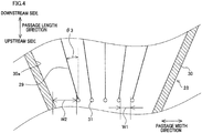
- FIG. 4 is an enlarged view of a lower (upstream) end portion of a later-described passage-enlarged portion 28.
- the up-down direction is the length direction (passage length direction) of the passage-enlarged portion 28.
- the upper side is the downstream side whereas the lower side is the upstream side.
- the left-right direction is the width direction (hereinafter, passage width direction) of the passage-enlarged portion 28.
- the duct 25 includes: a vertical passage portion 26 extending in the up-down direction; and a horizontal passage portion 27 extending in the front-rear direction.
- the lower end (upstream end) of the vertical passage portion 26 is connected to the compressed air source.
- the horizontal passage portion 27 extends horizontally from the upper end of the vertical passage portion 26, and is coupled to the rear side wall portion of the lower portion of the box 20. Air fed from the compressed air source flows to the box 20, through the vertical passage portion 26 and the horizontal passage portion 27 of the duct 25.
- the passage-enlarged portion 28 is formed at a downstream end portion of the vertical passage portion 26 of the duct 25.
- the passage width of the passage-enlarged portion 28 increases fanwise toward the downstream side.
- Two side walls 30 are formed at the respective end portions in the passage width direction of the passage-enlarged portion 28 to be symmetrical in the passage width direction. Each of these side walls 30 obliquely extends relative to the passage length direction.
- Each of the two side walls 30 has an inner wall surface 30a which forms the internal space of the passage-enlarged portion 28. That is to say, in FIG. 3(a) , a region surrounded by the two inner wall surfaces 30a and two two-dot chain lines is the internal space of the passage-enlarged portion 28.
- the length of the inner wall surface 30a in the passage length direction is referred to as the length X1.
- the horizontal passage portion 27 is connected to the downstream end portion of the passage-enlarged portion 28. From a different perspective, the passage width of the duct 25 is increased at the passage-enlarged portion 28, and the horizontal passage portion 27 connected to the passage-enlarged portion 28 extends to the box 20 while keeping the increased passage width.
- a plurality of (five in FIG. 3(a) ) partition plates 29 are provided to be lined up in the passage width direction.
- the partition plates 29 are provided to adjust an airflow so that air in the passage-enlarged portion 28 evenly spreads in the passage width direction.
- the partition plates 29 are radially provided from an upstream inlet portion 28a where the passage width is narrow toward a downstream outlet portion 28b where the passage width is wide.
- the partition plates 29 are substantially identical with one another in length.
- the partition plates 29 are arranged at substantially equal intervals with an angle ⁇ 1.
- a partition plate 29 provided at a central part in the passage width direction of the passage-enlarged portion 28 is provided along the passage length direction, whereas a partition plate 29 provided at an outer part in the passage width direction is inclined with respect to the passage length direction.
- the partition plate 29 which is closest to the inner wall surface 30a is provided to form an angle ⁇ 2 with the inner wall surface 30a.
- the angle ⁇ 1 is substantially equal to the angle ⁇ 2.
- the partition plates 29 which are provided at the end portions in the passage width direction are the shortest among the partition plates 29.
- the length of each of these shortest partition plates 29 in the passage length direction is referred to as the length X2.
- the lengths of the other partition plates 29 in the passage length direction are more than the length X2.
- the air flowing along the small passages 33 spreads in the passage width direction, and further flows toward the outlet portion 28b where the passage width is wide (see an arrow 103 in FIG. 3(a) ).
- the present embodiment employs the following structure.
- a bulging portion 31 is provided at an upstream end portion of each partition plate 29.
- the bulging portion 31 is, for example, formed by attaching, to an upstream end portion of the partition plate 29, a round bar 32 extending in the height direction (which is the direction orthogonal to the plane of the figure and will be simply referred to as the height direction) of the partition plate 29, which is the direction orthogonal to the passage length direction and is orthogonal to the passage width direction (see FIG. 3(b) ).
- the cross section of the bulging portion 31 taken in the direction orthogonal to the height direction is circular in shape.
- the bulging portion 31 increases in size toward the downstream side from the upstream end portion to an intermediate portion of the bulging portion 31.
- the bulging portion 31 increases in size in the passage width direction from the upstream end portion toward the downstream side.
- the bulging portion 31 includes a part which increases in size in the passage width direction from the upstream end portion toward the downstream side.
- the bulging portions 31 are lined up to form a single line along the passage width direction, i.e., linearly lined up.
- the length W1 is the shortest length of the gap between two bulging portions 31 (i.e., the length of the gap between end portions in the passage width direction of two bulging portions 31 in the present embodiment).
- the length W2 is the length of the gap in the passage width direction between the inner wall surface 30a and an end in the passage width direction of the bulging portion 31 of the partition plate 29 which is closest to the inner wall surface 30a.
- each partition plate 29 does not have the bulging portion 31.
- the bulging portions 31 are provided at the upstream end portions of the respective partition plates 29 in the present embodiment, and the upstream side part 31a of each bulging portion 31 increases in size in the passage width direction toward the downstream side. This facilitates part of the air coming from the upstream side to smoothly flow along the surface of each bulging portion 31.
- the inventor of the subject application found that the following conditions regarding the locations and arrangements of the partition plates 29 and the bulging portions 31 significantly influenced on the airflow adjustment effect.
- the airflow adjustment effect was improved by setting each of the following factors to fall within a suitable range: (1) the length W1 of the gap between the bulging portions 31; (2) the ratio (W2/W1) of the length W2 of the gap between the inner wall surface 30a and the bulging portion 31 to the length W1; (3) the ratio (X2/X1) of the length in the passage length direction of the partition plate 29 to the length in the passage length direction of the inner wall surface 30a; and (4) the diameter of the bulging portion 31 in cross section.
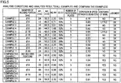
- FIG. 5 to FIG. 8(b) are tables showing the details of the analysis conditions and the analysis results.
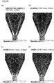
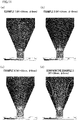
- FIG. 9(a) to FIG. 17(d) show analysis results of Examples and Comparative Examples (the speed distributions in the passage-enlarged portion 28 in cross section corresponding to FIG. 3(a) ).
- FIG. 5 shows analysis conditions and analysis results of all examples (Examples 1 to 11) and all comparative examples (Comparative Examples 1 to 6), whereas each of FIG. 6(a) to FIG. 8(b) shows the dependency on a parameter of examples and comparative examples.
- a parameter concerning each dependency is surrounded by a thick-bordered frame.
- FIG. 9(a) to FIG. 17(d) each showing the speed distribution, the air speed is low at a dark part whereas the air speed is high at a light gray part.
- FIG. 5 to FIG. 8(b) show, as specific conditions, the diameter of the bulging portion 31, the length W1, the length W2, the ratio W2/W1, and the ratio X2/X1.
- the number of the partition plates 29 is also shown because the number of the partition plates 29 is different in an example (Example 7).
- FIG. 5 to FIG. 8(b) show the degree of dispersion in speed of air at a downstream end portion of the passage-enlarged portion 28 (i.e., a standard deviation of speed; hereinafter, this will be simply referred to as standard deviation), generation of a whirl in the passage-enlarged portion 28, and judgment (OK or NG).
- the standard deviation was calculated from data of the air speed distribution in a cross section (orthogonal to the passage length direction) of the downstream end portion of the passage-enlarged portion 28.
- Whether a whirl was generated was determined by visually checking the speed distribution figures in FIG. 9(a) to FIG. 17(d) . (Generated whirls are indicated by white circles in FIG. 9(a) to FIG. 17(d) .) Energy loss increases when a whirl is generated. Furthermore, a whirl may increase the degree of dispersion in speed of air.
- the inventor of the subjection application understands the results described above as below.
- the length W1 is too short, an airflow from the upstream side tends to be obstructed by the bulging portions 31, with the result that the air does not easily flow into the small passages 33 between the partition plates 29, and the flow adjustment effect by the partition plates 29 is insufficient.
- the length W1 is too long, the intervals of the partition plates 29 are also too long, with the result that the flow adjustment effect by the partition plates 29 is insufficient also in this case.
- the length W1 when the length W1 is 12mm or longer, obstruction to air entrance into the intervals between the partition plates 29 by the bulging portions 31 is restrained. Meanwhile, when the length W1 is 30 mm or shorter, the intervals between the partition plates 29 are not too long. With these arrangements, the partition plates 29 properly exert the flow adjustment effect and the degree of dispersion in speed of air is small. More preferably, when the length W1 is arranged to be equal to or longer than 18mm and equal to or shorter than 30mm, the degree of dispersion in speed of air is further decreased and the generation of whirls is restrained.
- the degree of dispersion in speed of air is restrained to be small. More preferably, the degree of dispersion in speed of air is further restrained when the length W2 is 1.5 times or more longer than the length W1 and 5.5 times or less longer than the length W1.
- each partition plate 29 preferably has at least predetermined length (i.e., at least 26% of the length of the inner wall surface 30a) in the passage length direction. Basically, the longer each partition plate 29 is, the better. For this reason, in the passage length direction, the length of each partition plate 29 is more preferably 50% or more of the length of the inner wall surface 30a, and further preferably 75% or more of the length of the inner wall surface 30a.
- the diameter of the bulging portion was changed within the range of ⁇ 4mm to ⁇ 20mm, and comparisons were made in regard to the standard deviation and the formation of a whirl (Examples 1, 6, 10, and 11) .
- the standard deviation was 0.85 or smaller and the formation of whirls was not observed (see FIGs. 17(a) to 17(d) ).
- each bulging portion 31 When each bulging portion 31 is too small, the effect of allowing air in contact with the partition plate 29 to smoothly move may be deteriorated. Meanwhile, when each bulging portion 31 is too large, as described above, it is necessary to increase the intervals between the partition plates 29 in order to maintain the length W1 to fall within the predetermined range. Because as a result of this the width of each small passages 33 rapidly increases at the immediate downstream of the bulging portions 31, the airflow may become destabilized. For this reason, it is preferable that the diameter of the cross section of each bulging portion 31 is preferably not less than 4mm and not more than 20mm.
- the bulging portion 31 formed at each partition plate 29 includes a part which increases in size in the passage width direction from the end portion on the upstream side toward the downstream side, part of the air flowing from the upstream side is encouraged to smoothly flow along the surface of the bulging portion 31. This prevents the airflow from being detached from the partition plate 29 and disturbed.
- the length W1 between the two bulging portions 31 is 12mm or longer, obstruction to the airflow by the bulging portions 31 is restrained. Furthermore, because the length W1 is 30 mm or shorter, the intervals between the partition plates 29 are not too long, and the flow adjustment effect exerted by the partition plates 29 is facilitated.
- the length W1 is set to be to shorter than 18mm and not longer than 30mm (i.e., by increasing the lower limit value of the length W1), obstruction to the airflow by the bulging portions is further suppressed, and the dispersion in speed of air is further suppressed.
- the length W2 of the gap in the passage width direction between the inner wall surface 30a of the passage-enlarged portion 28 and the partition plate 29 closest to the inner wall surface 30a is set to be equal to or longer than the length W1 and seven times or less longer than the length W1
- the balance between the speed of air at the end portions in the passage width direction and the speed of air at the central portion in the passage width direction is improved in the passage-enlarged portion 28, with the result that the dispersion in speed of air is restrained.
- the length W2 to be 1.5 times or more longer than the length W1 and 5.5 times or less longer than the length W1
- the balance of the speed of the air in the passage width direction is further improved.
- each partition plate 29 is 26% or more of the inner wall surface 30a in length, the air is properly guided outward in the passage width direction by the partition plates 29, and hence the air is evenly spread to reach the end portions in the passage width direction.
- the bulging portions 31 are lined up to form a single line along the passage width direction.
- the bulging portions 31 are linearly lined up along the passage width direction.
- each bulging portion is 4mm or longer and 20mm or shorter, smooth movement of the air in contact with each partition plate 29 is ensured, rapid increase in width of each small passage 33 is restrained at the immediate downstream of each bulging portion 31, and destabilization of the airflow is restrained.
Landscapes
- Engineering & Computer Science (AREA)
- Mechanical Engineering (AREA)
- Textile Engineering (AREA)
- Spinning Methods And Devices For Manufacturing Artificial Fibers (AREA)
- Separation By Low-Temperature Treatments (AREA)
Abstract
Description
- The present invention relates to a yarn cooler configured to cool yarns spun out from a spinning beam.
- Patent Literature 1 (Japanese Unexamined Patent Publication No.
2011-252260 - In this yarn cooler, a passage-enlarged portion in which the passage width increases toward the downstream side is provided at an intermediate portion of the duct in order to arrange the width of a downstream portion (a portion on the yarn cooling unit side) of the passage to be more or less identical with the width of the yarn cooling unit. In this regard, when nothing is provided in the passage-enlarged portion, air uninterruptedly flows from the upstream side to the downstream side. The speed of the air is therefore relatively high at a central portion in the width direction of the passage and is relatively low at outer end portions in the width direction. When the speed of the air is significantly different at different positions in the width direction, the yarns may not be evenly cooled at the yarn cooling unit and the yarn quality may be uneven. It is therefore necessary to adjust the airflow in the passage-enlarged portion to restrain the dispersion in speed of air in the width direction.
- In connection with the above, Patent Literature 2 (Japanese Unexamined Patent Publication No.
H8-201215 - The partition plates are provided in a simple manner in the arrangement disclosed in
Patent Literature 2. This arrangement may be disadvantageous in that the airflow is disturbed as the air collides with an upstream end portion of each partition plate, with the result that the airflow adjustment is not effectively done. Under this circumstance, a technology for firmly enhancing the effect of the airflow adjustment by the partition plates has been demanded. - An object of the present invention is to suppress the disturbance of a gas flow even if gas flowing in a passage-enlarged portion collides with an upstream end portion of a partition plate, and to suppress dispersion in speed of gas.
- According to the first aspect of the invention, a yarn cooler includes: a yarn cooling unit configured to cool a yarn spun out from a spinning apparatus, by applying gas to the yarn; and a duct in which a passage where the gas supplied to the yarn cooling unit flows is formed, the duct including: a passage-enlarged portion including an inner wall surface which is formed to increase the width of the passage from an upstream side toward a downstream side of the passage; and partition plates which are lined up in a passage width direction and are radially provided from the upstream side toward the downstream side, in the passage-enlarged portion, bulging portions being formed at end portions on the upstream side of the respective partition plates, each of the bulging portions including a part which increases in size in the passage width direction from the end portion on the upstream side of the bulging portion toward the downstream side, and the length of a gap between two bulging portions of neighboring two of the partition plates being 12mm or longer and 30mm or shorter.
- In the present invention, gas flowing through the passage enters the yarn cooling unit while spreading on account of the passage-enlarged portion. In the passage-enlarged portion, the passage is divided into small passages by the partition plates. With this arrangement, the gas flows to downstream side through any small passages. According to the present invention, each of the bulging portions formed on the respective partition plates includes a part which increases in size in the passage width direction from the end portion on the upstream side toward the downstream side. This facilitates part of the gas coming from the upstream side to smoothly flow along the surface of each bulging portion. This prevents the gas flow from being detached from the partition plate and disturbed.
- As a result of diligent study, the inventor of the subject application found that the size of the gap between two bulging portions significantly influenced on the dispersion in speed of the gas. To be more specific, the inventor of the subject application found that the obstruction to the gas flow by the bulging portions was restrained when the length of a gap between the two bulging portions was 12mm or longer, as in the present invention. The inventor also found that, when the length of the gap was 30 mm or shorter, the intervals between the partition plates were not too long, and the flow adjustment effect exerted by the partition plates was facilitated.
- As described above, disturbance of a gas flow is suppressed even if gas flowing in a passage-enlarged portion collides with an upstream end portion of a partition plate, and dispersion in speed of gas is suppressed.
- According to the second aspect of the invention, the yarn cooler of the first aspect is arranged such that the length of the gap between the two bulging portions of the neighboring two of the partition plates is equal to or longer than 18mm and equal to or shorter than 30mm.
- According to the present invention, by setting the length of the gap between the two bulging portions to be not shorter than 18mm and not longer than 30mm (i.e., by setting the lower limit value of the this length to be longer than that in the first aspect), obstruction to the gas flow by the bulging portions is further suppressed, and the dispersion in speed of air is further suppressed.
- According to the third aspect of the invention, the yarn cooler of the first or second aspect is arranged such that the length of a gap between the inner wall surface of the passage-enlarged portion and a bulging portion of a partition plate which is closest to the inner wall surface is equal to or longer than the length of the gap between the two bulging portions of the neighboring two of the partition plates and seven times or less longer than the length of the gap between the two bulging portions of the neighboring two of the partition plates.
- In regard to the first or second aspect of the invention, the inventor of the subject application also found that the relationship between (i) the length of the gap between the inner wall surface of the passage-enlarged portion and the bulging portion closest to the inner wall surface and (ii) the length of the gap between the two bulging portions significantly influenced on the dispersion in speed of the gas. When the former length is relatively too long, the gas excessively flows into the gap between the inner wall surface of the passage-enlarged portion and the partition plate (i.e., into the end portion in the passage width direction in the passage-enlarged portion), with the result that the degree of dispersion in speed of the gas is high. Meanwhile, when the former length is relatively too short, the gas excessively flows into the intervals between the partition plates (i.e., into a central portion in the passage width direction in the passage-enlarged portion). According to the present invention, by setting the former length to be equal to or longer than the latter length and seven times or less longer than the latter length, the balance between the speed of the gas at the end portions in the passage width direction and the speed of air at the central portion in the passage width direction is improved in the passage-enlarged portion, with the result that the dispersion in speed of air is restrained.
- According to the fourth aspect of the invention, the yarn cooler of the third aspect is arranged such that the length of the gap between the inner wall surface of the passage-enlarged portion and the bulging portion of the partition plate which is closest to the inner wall surface is 1.5 times or more longer than and 5.5 times or less longer than the length of the gap between the two bulging portions of the neighboring two of the partition plates.
- According to the present invention, by setting the length of the gap between the inner wall surface of the passage-enlarged portion and the bulging portion closest to the inner wall surface to be 1.5 times or more longer than and 5.5 times or less longer than the length of the gap between the two bulging portions, the balance of the speed of the gas in the passage width direction is further improved.
- According to the fifth aspect of the invention, the yarn cooler of any one of the first to fourth aspects is arranged such that, in a passage length direction which is orthogonal to the passage width direction, the length of each of the partition plates is at least 26% of the length of the inner wall surface.
- When the partition plate is too short, the gas may not sufficiently spread to the outer sides in the passage width direction in the passage-enlarged portion. According to the present invention, because in the passage length direction each partition plate is 26% or more of the inner wall surface in length, the gas is properly guided outward in the passage width direction by the partition plates, and hence the gas is evenly spread to reach the end portions in the passage width direction.
- According to the sixth aspect of the invention, the yarn cooler of any one of the first to fifth aspects is arranged such that the bulging portions of the partition plates are lined up along the passage width direction to form a single line.
- When the bulging portions are arranged, for example, in an arc shape or in a staggered manner, the length of the gap between two bulging portions tends to be long, and hence the number of the partition plates required to keep the length to be equal to or shorter than a predetermined length may be large. According to the present invention, the bulging portions are lined up to form a single line along the passage width direction, i.e., linearly lined up. Because this restrains the length of the gap between the two bulging portions from becoming long, it is possible to restrain increase in number of the required partition plates. Furthermore, when, for example, the bulging portions are provided to be arc-shaped or in a staggered manner in the production of the passage-enlarged portion, arranging the bulging portions may require a lot of labor if the length of the gap between each pair of bulging portions is taken into account. Such labor is reduced in the present invention.
- According to the seventh aspect of the invention, the yarn cooler of any one of the first to sixth aspects is arranged such that a cross sectional shape of each of the bulging portions is circular, and the diameter of each of the bulging portions is not less than 4mm and not more than 20mm.
- According to the present invention, because the cross sectional shape of the bulging portion is circular, the gas flowing from the upstream side smoothly move to the downstream side. However, when the diameter of the bulging portion is short, the effect of allowing the gas in contact with the partition plate to smoothly move may be deteriorated. Meanwhile, when the diameter of the bulging portion is long, it is necessary to increase the intervals between the partition plates in order to maintain the length of the gap between the bulging portions to fall within the predetermined range. Because as a result of this the width of the passage rapidly increases at the immediate downstream of the bulging portions, the gas flow may become destabilized. For this reason, it is preferable that the diameter of each bulging portion is not less than 4mm and not more than 20mm.
-
-
FIG. 1 is a cross section of a melt spinning device of an embodiment of the present invention. -
FIG. 2 is a cross section taken along a line II-II inFIG. 1 . -
FIG. 3(a) is a cross section of a passage-enlarged portion taken along a line III-III inFIG. 1 .FIG. 3(b) is an enlarged view of a bulging portion of each partition plate inFIG. 3(a) . -
FIG. 4 is an enlarged view of an upstream end portion of a passage-enlarged portion. -
FIG. 5 shows conditions of all Examples and Comparative Examples and data of the degree of dispersion in speed of air obtained through fluid analysis. -
FIGs. 6(a) and 6(b) show conditions of some Examples and Comparative Examples and data of the degree of dispersion in speed of air obtained through fluid analysis. -
FIG. 7 shows conditions of some Examples and Comparative Examples and data of the degree of dispersion in speed obtained through fluid analysis. -
FIGs. 8(a) and 8(b) show conditions of some Examples and Comparative Examples and data of the degree of dispersion in speed obtained through fluid analysis. -
FIGs. 9(a) and 9(b) show analysis results (speed distributions in the passage-enlarged portion) regarding the dependency on the existence of bulging portions. -
FIGs. 10(a) to 10(d) show analysis results regarding the dependency on the length of the gap between the bulging portions. -
FIGs. 11(a) to 11(d) show analysis results regarding the dependency on the length of the gap between the bulging portions. -
FIGs. 12(a) and 12(b) show analysis results regarding the dependency on the length of the gap between the bulging portions. -
FIGs. 13(a) to 13(d) show analysis results regarding the dependency on the ratio between two types of gap lengths concerning the bulging portions. -
FIGs. 14(a) to 14(d) show analysis results regarding the dependency on the ratio between two types ofgap lengths concerning the bulging portions. -
FIGs. 15(a) to 15(c) show analysis results regarding the dependency on the ratio between two types of gap lengths concerning the bulging portions. -
FIGs. 16(a) to 16(d) show analysis results regarding the dependency on the length of a partition plate. -
FIGs. 17(a) to 17(d) show analysis results regarding the dependency on the diameter of the bulging portion. -
FIG. 18 illustrates a passage-enlarged portion of a modification. - The following will describe an embodiment of the present invention with reference to
FIG. 1 to FIG. 17 . - To begin with, the structure of a
melt spinning device 1 will be described with reference toFIG. 1 andFIG. 2 .FIG. 1 is a cross section of the melt spinning device of the present embodiment.FIG. 2 is a cross section taken along a line II-II inFIG. 1 . The description below is given on the premise that the up-down direction, front-rear direction, and left-right direction inFIG. 1 andFIG. 2 are respectively the up-down direction, front-rear direction, and left-right direction relative to themelt spinning device 1 in the present embodiment. Themelt spinning device 1 includes members such as a spinning beam 2 (spinning apparatus of the present invention), ayarn cooler 3, and anoil guide 4. - The
spinning beam 2 is configured to spin out yarns Y which are made of molten polymer. Thespinning beam 2 is provided with a plurality ofpack housings 11. To thepack housings 11, spinning packs 12 are attached, respectively. The pack housings 11 (spinning packs 12) are staggered to form two lines along the left-right direction. To each spinningpack 12, molten polymer is supplied from an unillustrated pipe or the like. Each spinningpack 12 has, at its lower end portion, aspinneret 13 having nozzles (not illustrated). The supplied molten polymer is spun out from the spinningpack 12 through the nozzles of thespinneret 13. The polymer spun out through the nozzles is cooled at theyarn cooler 3 into filaments f. Theyarn cooler 3 will be described later. To put it differently, one multi-filament yarn Y formed of plural filaments f is spun out from onespinneret 13. - The
yarn cooler 3 is provided to cool and solidify molten polymer spun out from the spinning packs 12. Theyarn cooler 3 is located below thespinning beam 2. As shownFIG. 1 andFIG. 2 , theyarn cooler 3 includes members such as: abox 20; cooling cylinders 21 (yarn cooling units of the present invention) accommodated in thebox 20; andpartitioning cylinders 22. - As shown in
FIG. 1 , the internal space of thebox 20 is partitioned by aflow adjustment plate 23 into upper and lower spaces. Theflow adjustment plate 23 is formed by a material such as punching metal having a flow adjustment function, and is horizontally provided. In the upper space (above the flow adjustment plate 23) of thebox 20, the coolingcylinders 21 are provided to be directly below the spinning packs 12, respectively. The coolingcylinders 21 are staggered along the left-right direction in accordance with the arrangement of the spinning packs 12, as shown inFIG. 2 . The wall of each coolingcylinder 21 is, in a manner similar to theflow adjustment plate 23, made of a material having flow adjustment capability such as punching metal. In the lower space (below the flow adjustment plate 23) of thebox 20, thepartitioning cylinders 22 are provided to be directly below the coolingcylinders 21, respectively. Being different from the coolingcylinders 21, the wall of eachpartitioning cylinder 22 is made of an air-impermeable material. A yarn Y passes through the internal spaces of thecooling cylinder 21 and thepartitioning cylinder 22 which are directly below the spinningpack 12. - A
duct 25 is connected to a rear side part of a lower portion of the box 20 (seeFIG. 1 ). Theduct 25 is connected to a compressed air source (not illustrated). The compressed air source feeds air for cooling the yarns Y to the inside of theduct 25. The air from the compressed air source is supplied to the lower space of thebox 20 through theduct 25. Theduct 25 will be detailed later. - The flow of cooling air having entered the lower space of the
box 20 is adjusted upward while passing through the horizontalflow adjustment plate 23, and flows into the upper space of thebox 20. The flow of the air having entered the upper space of thebox 20 is adjusted when passing through the wall of each coolingcylinder 21, and flows into each coolingcylinder 21. The air is blown to each yarn Y from the entire outer circumference of thecorresponding cooling cylinder 21, so that each yarn Y is cooled in thecorresponding cooling cylinder 21. Because the wall of eachpartitioning cylinder 22 is air-impermeable, the cooling air does not directly flow from the lower space of thebox 20 into thepartitioning cylinder 22. - The
oil guide 4 is configured to apply oil to the yarns Y. Theoil guide 4 is provided below the corresponding coolingcylinder 21 andpartitioning cylinder 22. The yarn Y having been cooled in thecooling cylinder 21 comes into contact with theoil guide 4. During this contact, theoil guide 4 discharges oil to the yarn Y so that the oil is applied to the yarn Y. The yarn Y to which the oil has been applied by theoil guide 4 is taken up by a take-up roller (not illustrated)) provided below theoil guide 4. The yarn Y is then sent to a winding device (not illustrated) and is wound onto a bobbin (not illustrated) at the winding device. - The following will describe the structure of the
duct 25 of theyarn cooler 3 with reference toFIG. 1 ,FIGs. 3(a) and 3(b) , andFIG. 4 .FIG. 3(a) is a cross section taken along a line III-III inFIG. 1 .FIG. 3(b) is an enlarged view of a bulgingportion 31 of a later-describedpartition plate 29.FIG. 4 is an enlarged view of a lower (upstream) end portion of a later-described passage-enlargedportion 28. Hereinafter, in the explanation of the passage-enlargedportion 28, the up-down direction is the length direction (passage length direction) of the passage-enlargedportion 28. The upper side is the downstream side whereas the lower side is the upstream side. Furthermore, the left-right direction is the width direction (hereinafter, passage width direction) of the passage-enlargedportion 28. - The
duct 25 includes: avertical passage portion 26 extending in the up-down direction; and ahorizontal passage portion 27 extending in the front-rear direction. The lower end (upstream end) of thevertical passage portion 26 is connected to the compressed air source. Thehorizontal passage portion 27 extends horizontally from the upper end of thevertical passage portion 26, and is coupled to the rear side wall portion of the lower portion of thebox 20. Air fed from the compressed air source flows to thebox 20, through thevertical passage portion 26 and thehorizontal passage portion 27 of theduct 25. - As shown in
FIG. 3(a) , the passage-enlargedportion 28 is formed at a downstream end portion of thevertical passage portion 26 of theduct 25. The passage width of the passage-enlargedportion 28 increases fanwise toward the downstream side. Twoside walls 30 are formed at the respective end portions in the passage width direction of the passage-enlargedportion 28 to be symmetrical in the passage width direction. Each of theseside walls 30 obliquely extends relative to the passage length direction. Each of the twoside walls 30 has aninner wall surface 30a which forms the internal space of the passage-enlargedportion 28. That is to say, inFIG. 3(a) , a region surrounded by the two inner wall surfaces 30a and two two-dot chain lines is the internal space of the passage-enlargedportion 28. The length of theinner wall surface 30a in the passage length direction is referred to as the length X1. Thehorizontal passage portion 27 is connected to the downstream end portion of the passage-enlargedportion 28. From a different perspective, the passage width of theduct 25 is increased at the passage-enlargedportion 28, and thehorizontal passage portion 27 connected to the passage-enlargedportion 28 extends to thebox 20 while keeping the increased passage width. - In the passage-enlarged
portion 28, a plurality of (five inFIG. 3(a) )partition plates 29 are provided to be lined up in the passage width direction. Thepartition plates 29 are provided to adjust an airflow so that air in the passage-enlargedportion 28 evenly spreads in the passage width direction. Thepartition plates 29 are radially provided from anupstream inlet portion 28a where the passage width is narrow toward adownstream outlet portion 28b where the passage width is wide. Thepartition plates 29 are substantially identical with one another in length. Thepartition plates 29 are arranged at substantially equal intervals with an angle θ1. To be more specific, apartition plate 29 provided at a central part in the passage width direction of the passage-enlargedportion 28 is provided along the passage length direction, whereas apartition plate 29 provided at an outer part in the passage width direction is inclined with respect to the passage length direction. Thepartition plate 29 which is closest to theinner wall surface 30a is provided to form an angle θ2 with theinner wall surface 30a. In the present embodiment, the angle θ1 is substantially equal to the angle θ2. - In the passage length direction, the
partition plates 29 which are provided at the end portions in the passage width direction (i.e., which are most inclined with respect to the passage length direction) are the shortest among thepartition plates 29. The length of each of theseshortest partition plates 29 in the passage length direction is referred to as the length X2. The lengths of theother partition plates 29 in the passage length direction are more than the length X2. - In the passage-enlarged
portion 28 structured as described above, air flows into the passage-enlargedportion 28 through theinlet portion 28a (see anarrow 101 inFIG. 3(a) ), and then flows intosmall passages 33 which are formed by the partition plates 29 (see anarrow 102 inFIG. 3(a) ). The air flowing along thesmall passages 33 spreads in the passage width direction, and further flows toward theoutlet portion 28b where the passage width is wide (see anarrow 103 inFIG. 3(a) ). - In regard to the above, if the
partition plate 29 are not properly disposed or arranged, the airflow cannot be effectively adjusted, and hence dispersion in speed in the passage width direction may be significant at around theoutlet portion 28b. When air with large dispersion in speed flows into thebox 20, the speed of the air is uneven between the coolingcylinders 21 in thebox 20. This results in differences in yarn cooling capability by air between the coolingcylinders 21, and hence the yarn quality may be uneven. To firmly enhance the airflow adjustment by thepartition plates 29 and to suppress the dispersion in air speed, the present embodiment employs the following structure. - As shown in
FIGs. 3(a) and 3(b) , a bulgingportion 31 is provided at an upstream end portion of eachpartition plate 29. The bulgingportion 31 is, for example, formed by attaching, to an upstream end portion of thepartition plate 29, around bar 32 extending in the height direction (which is the direction orthogonal to the plane of the figure and will be simply referred to as the height direction) of thepartition plate 29, which is the direction orthogonal to the passage length direction and is orthogonal to the passage width direction (seeFIG. 3(b) ). The cross section of the bulgingportion 31 taken in the direction orthogonal to the height direction is circular in shape. To put it differently, in the passage width direction, the bulgingportion 31 increases in size toward the downstream side from the upstream end portion to an intermediate portion of the bulgingportion 31. In other words, at anupstream side part 31a of the bulging portion 31 (i.e., a part surrounded by a two-dot chain line and a thick semicircle shown inFIG. 3(b) ), the bulgingportion 31 increases in size in the passage width direction from the upstream end portion toward the downstream side. To put it differently, the bulgingportion 31 includes a part which increases in size in the passage width direction from the upstream end portion toward the downstream side. - The bulging
portions 31 are lined up to form a single line along the passage width direction, i.e., linearly lined up. As shown inFIG. 4 , the length of the gap between two bulgingportions 31 provided at therespective partition plates 29 which are adjacent to each other is termed the length W1. To be more specific, the length W1 is the shortest length of the gap between two bulging portions 31 (i.e., the length of the gap between end portions in the passage width direction of two bulgingportions 31 in the present embodiment). Meanwhile, the length of the gap between theinner wall surface 30a and the bulgingportion 31 of thepartition plate 29 which is closest to theinner wall surface 30a is termed the length W2. To be more specific, the length W2 is the length of the gap in the passage width direction between theinner wall surface 30a and an end in the passage width direction of the bulgingportion 31 of thepartition plate 29 which is closest to theinner wall surface 30a. - Suppose that each
partition plate 29 does not have the bulgingportion 31. In this case, when air enters the passage-enlargedportion 28, the air collides with the upstream end portions of theflow adjustment plates 29. Thus, the flow of air is likely to be detached from thepartition plate 29 and disturbed. In this connection, the bulgingportions 31 are provided at the upstream end portions of therespective partition plates 29 in the present embodiment, and theupstream side part 31a of each bulgingportion 31 increases in size in the passage width direction toward the downstream side. This facilitates part of the air coming from the upstream side to smoothly flow along the surface of each bulgingportion 31. - In addition to the above, the inventor of the subject application found that the following conditions regarding the locations and arrangements of the
partition plates 29 and the bulgingportions 31 significantly influenced on the airflow adjustment effect. To be more specific, as a result of fluid analysis described below, the inventor found that the airflow adjustment effect was improved by setting each of the following factors to fall within a suitable range: (1) the length W1 of the gap between the bulgingportions 31; (2) the ratio (W2/W1) of the length W2 of the gap between theinner wall surface 30a and the bulgingportion 31 to the length W1; (3) the ratio (X2/X1) of the length in the passage length direction of thepartition plate 29 to the length in the passage length direction of theinner wall surface 30a; and (4) the diameter of the bulgingportion 31 in cross section. - The following describes the fluid analysis carried out by the inventor of the subject application. Conditions shared by all analytical models were as follows. The type of gas was air. Each of the angle θ1 and the angle θ2 (see
FIG. 3(a) ) was set at 8 degrees. The thickness of eachpartition plate 29 was 1mm. An amount of air flowing into theinlet portion 28a was 11.0m3/min. The number of the partition plates was 5 except in some examples. - The following will describe the details of the analysis conditions and analysis results, with reference to
FIG. 5 to FIG. 17(d) .FIG. 5 to FIG. 8(b) are tables showing the details of the analysis conditions and the analysis results.FIG. 9(a) to FIG. 17(d) show analysis results of Examples and Comparative Examples (the speed distributions in the passage-enlargedportion 28 in cross section corresponding toFIG. 3(a) ).FIG. 5 shows analysis conditions and analysis results of all examples (Examples 1 to 11) and all comparative examples (Comparative Examples 1 to 6), whereas each ofFIG. 6(a) to FIG. 8(b) shows the dependency on a parameter of examples and comparative examples. InFIG. 6(a) to FIG. 8(b) , a parameter concerning each dependency is surrounded by a thick-bordered frame. InFIG. 9(a) to FIG. 17(d) each showing the speed distribution, the air speed is low at a dark part whereas the air speed is high at a light gray part. -
FIG. 5 to FIG. 8(b) show, as specific conditions, the diameter of the bulgingportion 31, the length W1, the length W2, the ratio W2/W1, and the ratio X2/X1. In addition, the number of thepartition plates 29 is also shown because the number of thepartition plates 29 is different in an example (Example 7). As the analysis results,FIG. 5 to FIG. 8(b) show the degree of dispersion in speed of air at a downstream end portion of the passage-enlarged portion 28 (i.e., a standard deviation of speed; hereinafter, this will be simply referred to as standard deviation), generation of a whirl in the passage-enlargedportion 28, and judgment (OK or NG). - The standard deviation was calculated from data of the air speed distribution in a cross section (orthogonal to the passage length direction) of the downstream end portion of the passage-enlarged
portion 28. The smaller this standard deviation is, the smaller the degree of dispersion in speed of air is. Whether a whirl was generated was determined by visually checking the speed distribution figures inFIG. 9(a) to FIG. 17(d) . (Generated whirls are indicated by white circles inFIG. 9(a) to FIG. 17(d) .) Energy loss increases when a whirl is generated. Furthermore, a whirl may increase the degree of dispersion in speed of air. In regard to the judgment, an example in which the standard deviation was 0.85 or lower and the formation of a whirl of air (i.e., airflow disturbance) in the passage-enlargedportion 28 was inconspicuous was judged as OK, whereas an example which did not satisfy these conditions was judged as NG. The following will describe the analysis results related to the respective dependencies. - To begin with, as shown in
FIG. 6(a) , a case where the bulgingportions 31 were formed at the upstream end portions of thepartition plates 29 was compared with a case where no bulging portions were formed, in regard to the standard deviation and the formation of a whirl. Both in the case (Example 1) where the bulgingportions 31 were formed and the case (Comparative Example 1) where no bulgingportions 31 were formed, no whirl was formed (seeFIG. 9 ). However, the standard deviation was large, i.e., 0.89, and significant dispersion in speed was observed in Comparative Example 1. Meanwhile, the standard deviation was small, i.e., 0.75 and a good result was obtained in the Example. The analysis result shows that, because part of the air coming from the upstream side smoothly flows along the surface of each bulgingportion 31, the disturbance of the airflow is restrained and the degree of dispersion in speed of air is restrained to be low. - As shown in
FIG. 6(b) , fluid analysis was done regarding the dependency of the degree of dispersion in speed of air, etc. on the length W1. To be more specific, the length W1 was changed within the range of 6mm to 44mm, and comparisons were made in regard to the standard deviation and the formation of a whirl (Examples 1 to 6 and Comparative Examples 2 to 5). Furthermore, the diameter of the bulgingportion 31 was altered (ϕ8mm or (ϕ16mm). InFIG. 6(b) , the examples and the comparative examples are arranged in an ascending order of the length W1. - Consequently, irrespective of the diameter of the bulging
portion 31, in the cases (Examples 1 to 6) in which the length W1 was equal to or longer than 12mm and equal to or shorter than 30mm, good analysis results were obtained such that the standard deviation was equal to or smaller than 0.85 and the formation of a whirl was inconspicuous (seeFIG. 10 andFIG. 11 ). In particular, when the length W1 was equal to or longer than 18mm and equal to or shorter than 30mm, a better result was obtained, i.e., the formation of a whirl was not observed at all. A case where W1=12mm was judged as OK because, in the analysis results of some examples (Examples 2 and 5), small whirls were observed (seeFIGs. 10(b) and 10(c) ) but the standard deviation was small, i.e., 0.85 and the small whirls were considered to be small in energy loss. Meanwhile, when the length W1 was out of the range of 12mm or longer and 30mm or shorter (Comparative Examples 2 to 5), the standard deviation was large and large whirls were observed at end portions in the passage width direction of the passage-enlarged portion 28 (seeFIG. 10 to FIG. 12 ). - The inventor of the subjection application understands the results described above as below. When the length W1 is too short, an airflow from the upstream side tends to be obstructed by the bulging
portions 31, with the result that the air does not easily flow into thesmall passages 33 between thepartition plates 29, and the flow adjustment effect by thepartition plates 29 is insufficient. Meanwhile, when the length W1 is too long, the intervals of thepartition plates 29 are also too long, with the result that the flow adjustment effect by thepartition plates 29 is insufficient also in this case. On this account, it is necessary to arrange the length W1 to fall within the optimum range (more specifically, equal to or longer than 12mm and equal to or shorter than 30mm) in order to suppress the degree of dispersion in speed of air to be small in the passage width direction. To put it differently, when the length W1 is 12mm or longer, obstruction to air entrance into the intervals between thepartition plates 29 by the bulgingportions 31 is restrained. Meanwhile, when the length W1 is 30 mm or shorter, the intervals between thepartition plates 29 are not too long. With these arrangements, thepartition plates 29 properly exert the flow adjustment effect and the degree of dispersion in speed of air is small. More preferably, when the length W1 is arranged to be equal to or longer than 18mm and equal to or shorter than 30mm, the degree of dispersion in speed of air is further decreased and the generation of whirls is restrained. - As shown in
FIG. 7 , fluid analysis was done in regard to the dependency of the degree of dispersion in speed of air or the like on the ratio of W2/W1. To be more specific, the ratio W2/W1 was changed within the range of 0.35 to 15.4, and comparisons were made in regard to the standard deviation and the formation of a whirl (Examples 1 to 7 and Comparative Examples 2 to 5). InFIG. 7 , the examples and the comparative examples are arranged in an ascending order of the ratio W2/W1. - As a result, when the length W2 was equal to or longer than the length W1 and was seven times or less longer than the length W1 (Examples 1 to 7), the standard deviation was 0.85 or smaller and the formation of whirls was inconspicuous (see
FIG. 13 to FIG. 15 ). Furthermore, when the length W2 was 1.5 times or more longer than and 5.5 times or less longer than the length W1 (Examples 1, 3, 5, and 7), the standard deviation was lower than 0.8 and better results were obtained. Furthermore, even if the diameter of the bulgingportion 31 and the length W1 remained the same (Example 2 and Example 7), the standard deviation was significantly lowered and no whirl was generated when the ratio W2/W1 was changed from about 7 to about 5.5 (and the number of the partition plates was changed from 5 to 7 and the inclination of theinner wall surface 30a was changed in accordance with the change in the number of plates in Example 7). Meanwhile, when the ratio W2/W1 was out of the range of 1 or higher and 7 or lower (Comparative Examples 2 to 5), the degree of dispersion in speed of air was high and large whirls were observed (seeFIG. 13 andFIG. 15 ). - The inventor of the subjection application understands the results described above as below. When the length W2 is too short relative to the length W1, an airflow entering the gap between the
inner wall surface 30a and the partition plate 29 (at an end portion in the passage width direction in the passage-enlarged portion 28) is obstructed, with the result that the air speed becomes unbalanced in the passage width direction. Meanwhile, when the length W2 is too long relative to the length W1, excessive air flows into an end portion in the passage width direction in the passage-enlargedportion 28, with the result that the air speed becomes unbalanced in the passage width direction. It is therefore preferable to arrange the ratio W2/W1 to fall within an optimum range (to be more specific. one time or more and seven times or less). In this regard, when the length W2 is equal to or longer than the length W1, an airflow into the end portions in the passage width direction in the passage-enlargedportion 28 is facilitated. Meanwhile, when the length W2 is seven times or less longer than the length W1, excessive airflow into the end portions in the passage width direction in the passage-enlargedportion 28 is prevented. This improves the balance between the speed of air at the end portions in the passage width direction and the speed of air at the central portion in the width direction in the passage-enlargedportion 28, with the result that the degree of dispersion in speed of air is restrained to be small. More preferably, the degree of dispersion in speed of air is further restrained when the length W2 is 1.5 times or more longer than the length W1 and 5.5 times or less longer than the length W1. - The range of the ratio W2/W1 with which the degree of dispersion in speed of air is restrained to be low ranges from 1 to a value which is several times higher than 1, presumably because of the following reason. Because the
partition plates 29 are radially provided in the passage-enlargedportion 28, theoutermost partition plate 29 in the passage width direction forms an angle which is large to some degree with the passage length direction (see the angle θ3 inFIG. 4 ; in this analysis condition, θ3=2×θ1, i.e., 16 degrees). On this account, it is considered that a large amount of air among the air flowing from the upstream side and flowing on the outer side in the passage width direction makes contact with thepartition plate 29, and the air at the end portions in the passage width direction tends to slow down on account of friction between the air and thepartition plates 29. As such, the speed of the air flowing at the end portions in the passage width direction is not easily increased as compared to the air flowing at the central portion in the passage width direction. For this reason, it is considered that the speed of the air is unlikely to become unbalanced in the passage width direction even when the length W2 is considerably longer than the length W1. - As shown in
FIG. 8(a) , fluid analysis was done regarding the dependency of the degree of dispersion in speed of air or the like on the ratio X2/X1, while changing the ratio (X2/X1) of the length X2 in the passage length direction of thepartition plate 29 which was shortest in the passage length direction to the length X1 in the passage length direction of theinner wall surface 30a. To be more specific, the ratio X2/X1 was changed within the range of 13% to 78%, and comparisons were made in regard to the standard deviation and the formation of a whirl (Examples 1, 8, and 9 and Comparative Example 6). As a result, when the ratio X2/X1 was 26% or higher (Examples 1, 8, and 9), the standard deviation was 0.85 or smaller and the formation of whirls was not observed (seeFIGs. 16(b) to 16(d) ). In particular, the standard deviation was lowest in Example 9 in which the ratio X2/X1 was the highest (78%). Meanwhile, when thepartition plate 29 was short (Comparative Example 6), the standard deviation was large and the formation of whirls were conspicuous at end portions in the passage width direction in the passage-enlarged portion 28 (seeFIG. 16(a) ). - It is considered that this is because, the longer the
partition plate 29 is in the passage-enlargedportion 28, the more the air is guided outward in the passage width direction by thepartition plate 29. It is considered that, when thepartition plate 29 is too short, the air flows out to a region where thepartition plate 29 is not provided in the passage length direction, before the air sufficiently spreads outward in the passage width direction, with the result that the air does not evenly spread to the outer sides in the passage width direction in a sufficient manner. For this reason, eachpartition plate 29 preferably has at least predetermined length (i.e., at least 26% of the length of theinner wall surface 30a) in the passage length direction. Basically, the longer eachpartition plate 29 is, the better. For this reason, in the passage length direction, the length of eachpartition plate 29 is more preferably 50% or more of the length of theinner wall surface 30a, and further preferably 75% or more of the length of theinner wall surface 30a. - As shown in
FIG. 8(b) , the diameter of the bulging portion was changed within the range of ϕ4mm to ϕ20mm, and comparisons were made in regard to the standard deviation and the formation of a whirl (Examples 1, 6, 10, and 11) . As a result, in all examples, the standard deviation was 0.85 or smaller and the formation of whirls was not observed (seeFIGs. 17(a) to 17(d) ). - When each bulging
portion 31 is too small, the effect of allowing air in contact with thepartition plate 29 to smoothly move may be deteriorated. Meanwhile, when each bulgingportion 31 is too large, as described above, it is necessary to increase the intervals between thepartition plates 29 in order to maintain the length W1 to fall within the predetermined range. Because as a result of this the width of eachsmall passages 33 rapidly increases at the immediate downstream of the bulgingportions 31, the airflow may become destabilized. For this reason, it is preferable that the diameter of the cross section of each bulgingportion 31 is preferably not less than 4mm and not more than 20mm. - As described above, in the passage-enlarged
portion 28, because the bulgingportion 31 formed at eachpartition plate 29 includes a part which increases in size in the passage width direction from the end portion on the upstream side toward the downstream side, part of the air flowing from the upstream side is encouraged to smoothly flow along the surface of the bulgingportion 31. This prevents the airflow from being detached from thepartition plate 29 and disturbed. - Furthermore, because the length W1 between the two bulging
portions 31 is 12mm or longer, obstruction to the airflow by the bulgingportions 31 is restrained. Furthermore, because the length W1 is 30 mm or shorter, the intervals between thepartition plates 29 are not too long, and the flow adjustment effect exerted by thepartition plates 29 is facilitated. - In this way, the disturbance of the gas flow due to collision of gas flowing in the passage-enlarged
portion 28 with thepartition plates 29 is restrained, and the dispersion in speed of air is suppressed. - More preferably, by setting the length W1 to be to shorter than 18mm and not longer than 30mm (i.e., by increasing the lower limit value of the length W1), obstruction to the airflow by the bulging portions is further suppressed, and the dispersion in speed of air is further suppressed.
- In addition to the above, by setting the length W2 of the gap in the passage width direction between the
inner wall surface 30a of the passage-enlargedportion 28 and thepartition plate 29 closest to theinner wall surface 30a to be equal to or longer than the length W1 and seven times or less longer than the length W1, the balance between the speed of air at the end portions in the passage width direction and the speed of air at the central portion in the passage width direction is improved in the passage-enlargedportion 28, with the result that the dispersion in speed of air is restrained. Further preferably, by setting the length W2 to be 1.5 times or more longer than the length W1 and 5.5 times or less longer than the length W1, the balance of the speed of the air in the passage width direction is further improved. - Furthermore, because in the passage length direction each
partition plate 29 is 26% or more of theinner wall surface 30a in length, the air is properly guided outward in the passage width direction by thepartition plates 29, and hence the air is evenly spread to reach the end portions in the passage width direction. - In addition to the above, the bulging
portions 31 are lined up to form a single line along the passage width direction. In other words, the bulgingportions 31 are linearly lined up along the passage width direction. With this arrangement, the length W1 between two bulgingportions 31 is maintained to be short as compared to cases where, for example, the bulgingportions 31 are lined up to form an arc or lined up in a staggered manner. It is therefore possible to restrain increase in number of partition plates required to maintain the length W1 to be equal to or shorter than a predetermined length. Furthermore, labor required to line up the bulgingportions 31 while taking account of the length W1 is reduced. - In addition to the above, because the diameter of each bulging portion is 4mm or longer and 20mm or shorter, smooth movement of the air in contact with each
partition plate 29 is ensured, rapid increase in width of eachsmall passage 33 is restrained at the immediate downstream of each bulgingportion 31, and destabilization of the airflow is restrained. - The following will describe modifications of the above-described embodiment. The members identical with those in the embodiment above will be denoted by the same reference numerals and the explanations thereof are not repeated.
- (1) While in the embodiment above the
partition plates 29 are substantially identical with one another in length, the disclosure is not limited to this arrangement. For example, as shown inFIG. 18 , in aduct 25a, partition plates provided in the passage-enlargedportion 28 may be different from one another in length. For example, apartition plate 29a which is closest to theinner wall surface 30a may be the longest, whereas apartition plate 29b which is provided at a central portion in the passage width direction may be the shortest. In this way, it is possible to further efficiently spread the air in the passage width direction by elongating thepartition plate 29a provided at an end portion in the passage width direction. - (2) While in the embodiment above the
partition plates 29 extend from the upstream end portions (in the vicinity of theinlet portion 28a) toward the downstream side in the passage-enlargedportion 28, the disclosure is not limited to this arrangement. The upstream end portions of thepartition plates 29 may not be provided in the vicinity of theinlet portion 28a in the passage-enlargedportion 28. - (3) While in the embodiment above each bulging
portion 31 has a circular cross sectional shape, the disclosure is not limited to this arrangement. The cross sectional shape of the bulging portion may be elliptic, or may be triangular and have a corner protruding toward the upstream side. In other words, the bulging portion may be variously shaped on condition that the portion includes a part which increases in size in the passage width direction from an upstream end portion toward the downstream side. - (4) While in the embodiment above the bulging
portions 31 are linearly lined up along the passage width direction, the disclosure is not limited to this arrangement. For example, the bulgingportions 31 may be lined up to form an arc. - (5) Gas other than air may be supplied to the
duct 25.
Claims (7)
- A yarn cooler comprising:a yarn cooling unit configured to cool a yarn spun out from a spinning apparatus, by applying gas to the yarn; anda duct in which a passage where the gas supplied to the yarn cooling unit flows is formed,the duct including:a passage-enlarged portion including an inner wall surface which is formed to increase the width of the passage from an upstream side toward a downstream side of the passage; andpartition plates which are lined up in a passage width direction and are radially provided from the upstream side toward the downstream side, in the passage-enlarged portion,bulging portions being formed at end portions on the upstream side of the respective partition plates,each of the bulging portions including a part which increases in size in the passage width direction from the end portion on the upstream side of the bulging portion toward the downstream side, andthe length of a gap between two bulging portions of neighboring two of the partition plates being 12mm or longer and 30mm or shorter.
- The yarn cooler according to claim 1, wherein, the length of the gap between the two bulging portions of the neighboring two of the partition plates is equal to or longer than 18mm and equal to or shorter than 30mm.
- The yarn cooler according to claim 1 or 2, wherein, the length of a gap between the inner wall surface of the passage-enlarged portion and a bulging portion of a partition plate which is closest to the inner wall surface is equal to or longer than the length of the gap between the two bulging portions of the neighboring two of the partition plates and seven times or less longer than the length of the gap between the two bulging portions of the neighboring two of the partition plates.
- The yarn cooler according to claim 3, wherein, the length of the gap between the inner wall surface of the passage-enlarged portion and the bulging portion of the partition plate which is closest to the inner wall surface is 1.5 times or more longer than and 5.5 times or less longer than the length of the gap between the two bulging portions of the neighboring two of the partition plates.
- The yarn cooler according to any one of claims 1 to 4, wherein, in a passage length direction which is orthogonal to the passage width direction,
the length of each of the partition plates is at least 26% of the length of the inner wall surface. - The yarn cooler according to any one of claims 1 to 5, wherein, the bulging portions of the partition plates are lined up along the passage width direction to form a single line.
- The yarn cooler according to any one of claims 1 to 6, wherein, a cross sectional shape of each of the bulging portions is circular, and the diameter of each of the bulging portions is not less than 4mm and not more than 20mm.
Applications Claiming Priority (1)
| Application Number | Priority Date | Filing Date | Title |
|---|---|---|---|
| JP2017153109A JP6993135B2 (en) | 2017-08-08 | 2017-08-08 | Thread cooling device |
Publications (2)
| Publication Number | Publication Date |
|---|---|
| EP3441507A1 true EP3441507A1 (en) | 2019-02-13 |
| EP3441507B1 EP3441507B1 (en) | 2020-06-17 |
Family
ID=63173933
Family Applications (1)
| Application Number | Title | Priority Date | Filing Date |
|---|---|---|---|
| EP18185451.4A Active EP3441507B1 (en) | 2017-08-08 | 2018-07-25 | Yarn cooler |
Country Status (3)
| Country | Link |
|---|---|
| EP (1) | EP3441507B1 (en) |
| JP (1) | JP6993135B2 (en) |
| CN (2) | CN209039636U (en) |
Families Citing this family (1)
| Publication number | Priority date | Publication date | Assignee | Title |
|---|---|---|---|---|
| JP6993135B2 (en) * | 2017-08-08 | 2022-01-13 | Tmtマシナリー株式会社 | Thread cooling device |
Citations (4)
| Publication number | Priority date | Publication date | Assignee | Title |
|---|---|---|---|---|
| JPH08201215A (en) | 1995-01-23 | 1996-08-09 | Mitsubishi Heavy Ind Ltd | Rectifying duct |
| JP2003213517A (en) * | 2002-01-18 | 2003-07-30 | Toray Ind Inc | Method and apparatus for producing synthetic fiber |
| EP2392698A1 (en) * | 2010-06-04 | 2011-12-07 | TMT Machinery, Inc. | Filament cooler |
| CN105177738A (en) * | 2015-09-30 | 2015-12-23 | 苏州金泉新材料股份有限公司 | Cross air blow cooling device for melt spinning |
Family Cites Families (6)
| Publication number | Priority date | Publication date | Assignee | Title |
|---|---|---|---|---|
| JPS4636421Y1 (en) * | 1968-07-25 | 1971-12-15 | ||
| JPS51134462A (en) * | 1975-05-16 | 1976-11-20 | Sanyo Electric Co Ltd | A rectifier |
| JP2007063690A (en) * | 2005-08-30 | 2007-03-15 | Teijin Fibers Ltd | Device for cooling yarn |
| CN105650006A (en) * | 2012-04-03 | 2016-06-08 | 夏普株式会社 | Remote controller holding structure and ion delivery device and electrical apparatus incorporating the same |
| CN103526309B (en) * | 2013-10-18 | 2015-11-04 | 王振海 | A kind of many row's synthesis tow cooling systems |
| JP6993135B2 (en) * | 2017-08-08 | 2022-01-13 | Tmtマシナリー株式会社 | Thread cooling device |
-
2017
- 2017-08-08 JP JP2017153109A patent/JP6993135B2/en active Active
-
2018
- 2018-06-27 CN CN201821000212.XU patent/CN209039636U/en not_active Withdrawn - After Issue
- 2018-06-27 CN CN201810679035.0A patent/CN109385673B/en active Active
- 2018-07-25 EP EP18185451.4A patent/EP3441507B1/en active Active
Patent Citations (5)
| Publication number | Priority date | Publication date | Assignee | Title |
|---|---|---|---|---|
| JPH08201215A (en) | 1995-01-23 | 1996-08-09 | Mitsubishi Heavy Ind Ltd | Rectifying duct |
| JP2003213517A (en) * | 2002-01-18 | 2003-07-30 | Toray Ind Inc | Method and apparatus for producing synthetic fiber |
| EP2392698A1 (en) * | 2010-06-04 | 2011-12-07 | TMT Machinery, Inc. | Filament cooler |
| JP2011252260A (en) | 2010-06-04 | 2011-12-15 | Tmt Machinery Inc | Yarn cooling device |
| CN105177738A (en) * | 2015-09-30 | 2015-12-23 | 苏州金泉新材料股份有限公司 | Cross air blow cooling device for melt spinning |
Also Published As
| Publication number | Publication date |
|---|---|
| CN209039636U (en) | 2019-06-28 |
| JP2019031756A (en) | 2019-02-28 |
| CN109385673A (en) | 2019-02-26 |
| EP3441507B1 (en) | 2020-06-17 |
| CN109385673B (en) | 2022-11-29 |
| JP6993135B2 (en) | 2022-01-13 |
Similar Documents
| Publication | Publication Date | Title |
|---|---|---|
| EP3492634B1 (en) | Melt spinning device | |
| CN110541241B (en) | Apparatus and method for making spunbond nonwoven fabrics from continuous filaments | |
| JP6069019B2 (en) | Yarn cooling device | |
| EP3208367B1 (en) | Yarn cooler | |
| CA3041370C (en) | Apparatus and method for making spunbond from continuous filaments | |
| JP2015014071A (en) | Yarn cooling device | |
| EP3441507B1 (en) | Yarn cooler | |
| EP3147392B1 (en) | Melt spinning device | |
| JP2010070887A (en) | Cooling device for spinning and melt-spinning method | |
| JP2007063690A (en) | Device for cooling yarn | |
| EP3012354B1 (en) | Yarn cooler | |
| JP5925657B2 (en) | Melt spinning equipment | |
| JP4988318B2 (en) | Multi-spindle melt spinning apparatus and ultrafine multifilament yarn obtained therefrom | |
| EP3121312B1 (en) | Yarn cooler | |
| JP2006241611A (en) | Melt-spinning equipment of synthetic fiber | |
| JP2002038328A (en) | Melt spinning equipment | |
| JP2009068154A (en) | Yarn cooling device | |
| JP7149100B2 (en) | Spinning cooling device | |
| EP3800283B1 (en) | Yarn production system | |
| WO2025033484A1 (en) | Yarn cooling device | |
| JP2009228178A (en) | Apparatus and method for producing filament yarn | |
| JPH0323641B2 (en) |
Legal Events
| Date | Code | Title | Description |
|---|---|---|---|
| PUAI | Public reference made under article 153(3) epc to a published international application that has entered the european phase |
Free format text: ORIGINAL CODE: 0009012 |
|
| STAA | Information on the status of an ep patent application or granted ep patent |
Free format text: STATUS: THE APPLICATION HAS BEEN PUBLISHED |
|
| AK | Designated contracting states |
Kind code of ref document: A1 Designated state(s): AL AT BE BG CH CY CZ DE DK EE ES FI FR GB GR HR HU IE IS IT LI LT LU LV MC MK MT NL NO PL PT RO RS SE SI SK SM TR |
|
| AX | Request for extension of the european patent |
Extension state: BA ME |
|
| STAA | Information on the status of an ep patent application or granted ep patent |
Free format text: STATUS: REQUEST FOR EXAMINATION WAS MADE |
|
| 17P | Request for examination filed |
Effective date: 20190711 |
|
| RBV | Designated contracting states (corrected) |
Designated state(s): AL AT BE BG CH CY CZ DE DK EE ES FI FR GB GR HR HU IE IS IT LI LT LU LV MC MK MT NL NO PL PT RO RS SE SI SK SM TR |
|
| GRAP | Despatch of communication of intention to grant a patent |
Free format text: ORIGINAL CODE: EPIDOSNIGR1 |
|
| STAA | Information on the status of an ep patent application or granted ep patent |
Free format text: STATUS: GRANT OF PATENT IS INTENDED |
|
| INTG | Intention to grant announced |
Effective date: 20200207 |
|
| GRAS | Grant fee paid |
Free format text: ORIGINAL CODE: EPIDOSNIGR3 |
|
| GRAA | (expected) grant |
Free format text: ORIGINAL CODE: 0009210 |
|
| STAA | Information on the status of an ep patent application or granted ep patent |
Free format text: STATUS: THE PATENT HAS BEEN GRANTED |
|
| AK | Designated contracting states |
Kind code of ref document: B1 Designated state(s): AL AT BE BG CH CY CZ DE DK EE ES FI FR GB GR HR HU IE IS IT LI LT LU LV MC MK MT NL NO PL PT RO RS SE SI SK SM TR |
|
| REG | Reference to a national code |
Ref country code: GB Ref legal event code: FG4D |
|
| REG | Reference to a national code |
Ref country code: CH Ref legal event code: EP |
|
| REG | Reference to a national code |
Ref country code: DE Ref legal event code: R096 Ref document number: 602018005308 Country of ref document: DE |
|
| REG | Reference to a national code |
Ref country code: IE Ref legal event code: FG4D |
|
| REG | Reference to a national code |
Ref country code: AT Ref legal event code: REF Ref document number: 1281410 Country of ref document: AT Kind code of ref document: T Effective date: 20200715 |
|
| PG25 | Lapsed in a contracting state [announced via postgrant information from national office to epo] |
Ref country code: NO Free format text: LAPSE BECAUSE OF FAILURE TO SUBMIT A TRANSLATION OF THE DESCRIPTION OR TO PAY THE FEE WITHIN THE PRESCRIBED TIME-LIMIT Effective date: 20200917 Ref country code: GR Free format text: LAPSE BECAUSE OF FAILURE TO SUBMIT A TRANSLATION OF THE DESCRIPTION OR TO PAY THE FEE WITHIN THE PRESCRIBED TIME-LIMIT Effective date: 20200918 Ref country code: LT Free format text: LAPSE BECAUSE OF FAILURE TO SUBMIT A TRANSLATION OF THE DESCRIPTION OR TO PAY THE FEE WITHIN THE PRESCRIBED TIME-LIMIT Effective date: 20200617 Ref country code: SE Free format text: LAPSE BECAUSE OF FAILURE TO SUBMIT A TRANSLATION OF THE DESCRIPTION OR TO PAY THE FEE WITHIN THE PRESCRIBED TIME-LIMIT Effective date: 20200617 Ref country code: FI Free format text: LAPSE BECAUSE OF FAILURE TO SUBMIT A TRANSLATION OF THE DESCRIPTION OR TO PAY THE FEE WITHIN THE PRESCRIBED TIME-LIMIT Effective date: 20200617 |
|
| REG | Reference to a national code |
Ref country code: LT Ref legal event code: MG4D |
|
| REG | Reference to a national code |
Ref country code: NL Ref legal event code: MP Effective date: 20200617 |
|
| PG25 | Lapsed in a contracting state [announced via postgrant information from national office to epo] |
Ref country code: BG Free format text: LAPSE BECAUSE OF FAILURE TO SUBMIT A TRANSLATION OF THE DESCRIPTION OR TO PAY THE FEE WITHIN THE PRESCRIBED TIME-LIMIT Effective date: 20200917 Ref country code: HR Free format text: LAPSE BECAUSE OF FAILURE TO SUBMIT A TRANSLATION OF THE DESCRIPTION OR TO PAY THE FEE WITHIN THE PRESCRIBED TIME-LIMIT Effective date: 20200617 Ref country code: LV Free format text: LAPSE BECAUSE OF FAILURE TO SUBMIT A TRANSLATION OF THE DESCRIPTION OR TO PAY THE FEE WITHIN THE PRESCRIBED TIME-LIMIT Effective date: 20200617 Ref country code: RS Free format text: LAPSE BECAUSE OF FAILURE TO SUBMIT A TRANSLATION OF THE DESCRIPTION OR TO PAY THE FEE WITHIN THE PRESCRIBED TIME-LIMIT Effective date: 20200617 |
|
| REG | Reference to a national code |
Ref country code: AT Ref legal event code: MK05 Ref document number: 1281410 Country of ref document: AT Kind code of ref document: T Effective date: 20200617 |
|
| PG25 | Lapsed in a contracting state [announced via postgrant information from national office to epo] |
Ref country code: NL Free format text: LAPSE BECAUSE OF FAILURE TO SUBMIT A TRANSLATION OF THE DESCRIPTION OR TO PAY THE FEE WITHIN THE PRESCRIBED TIME-LIMIT Effective date: 20200617 Ref country code: AL Free format text: LAPSE BECAUSE OF FAILURE TO SUBMIT A TRANSLATION OF THE DESCRIPTION OR TO PAY THE FEE WITHIN THE PRESCRIBED TIME-LIMIT Effective date: 20200617 |
|
| PG25 | Lapsed in a contracting state [announced via postgrant information from national office to epo] |
Ref country code: ES Free format text: LAPSE BECAUSE OF FAILURE TO SUBMIT A TRANSLATION OF THE DESCRIPTION OR TO PAY THE FEE WITHIN THE PRESCRIBED TIME-LIMIT Effective date: 20200617 Ref country code: PT Free format text: LAPSE BECAUSE OF FAILURE TO SUBMIT A TRANSLATION OF THE DESCRIPTION OR TO PAY THE FEE WITHIN THE PRESCRIBED TIME-LIMIT Effective date: 20201019 Ref country code: IT Free format text: LAPSE BECAUSE OF FAILURE TO SUBMIT A TRANSLATION OF THE DESCRIPTION OR TO PAY THE FEE WITHIN THE PRESCRIBED TIME-LIMIT Effective date: 20200617 Ref country code: RO Free format text: LAPSE BECAUSE OF FAILURE TO SUBMIT A TRANSLATION OF THE DESCRIPTION OR TO PAY THE FEE WITHIN THE PRESCRIBED TIME-LIMIT Effective date: 20200617 Ref country code: CZ Free format text: LAPSE BECAUSE OF FAILURE TO SUBMIT A TRANSLATION OF THE DESCRIPTION OR TO PAY THE FEE WITHIN THE PRESCRIBED TIME-LIMIT Effective date: 20200617 Ref country code: SM Free format text: LAPSE BECAUSE OF FAILURE TO SUBMIT A TRANSLATION OF THE DESCRIPTION OR TO PAY THE FEE WITHIN THE PRESCRIBED TIME-LIMIT Effective date: 20200617 Ref country code: AT Free format text: LAPSE BECAUSE OF FAILURE TO SUBMIT A TRANSLATION OF THE DESCRIPTION OR TO PAY THE FEE WITHIN THE PRESCRIBED TIME-LIMIT Effective date: 20200617 Ref country code: EE Free format text: LAPSE BECAUSE OF FAILURE TO SUBMIT A TRANSLATION OF THE DESCRIPTION OR TO PAY THE FEE WITHIN THE PRESCRIBED TIME-LIMIT Effective date: 20200617 |
|
| PG25 | Lapsed in a contracting state [announced via postgrant information from national office to epo] |
Ref country code: PL Free format text: LAPSE BECAUSE OF FAILURE TO SUBMIT A TRANSLATION OF THE DESCRIPTION OR TO PAY THE FEE WITHIN THE PRESCRIBED TIME-LIMIT Effective date: 20200617 Ref country code: SK Free format text: LAPSE BECAUSE OF FAILURE TO SUBMIT A TRANSLATION OF THE DESCRIPTION OR TO PAY THE FEE WITHIN THE PRESCRIBED TIME-LIMIT Effective date: 20200617 Ref country code: IS Free format text: LAPSE BECAUSE OF FAILURE TO SUBMIT A TRANSLATION OF THE DESCRIPTION OR TO PAY THE FEE WITHIN THE PRESCRIBED TIME-LIMIT Effective date: 20201017 |
|
| REG | Reference to a national code |
Ref country code: DE Ref legal event code: R097 Ref document number: 602018005308 Country of ref document: DE |
|
| PG25 | Lapsed in a contracting state [announced via postgrant information from national office to epo] |
Ref country code: MC Free format text: LAPSE BECAUSE OF FAILURE TO SUBMIT A TRANSLATION OF THE DESCRIPTION OR TO PAY THE FEE WITHIN THE PRESCRIBED TIME-LIMIT Effective date: 20200617 |
|
| PLBE | No opposition filed within time limit |
Free format text: ORIGINAL CODE: 0009261 |
|
| STAA | Information on the status of an ep patent application or granted ep patent |
Free format text: STATUS: NO OPPOSITION FILED WITHIN TIME LIMIT |
|
| REG | Reference to a national code |
Ref country code: BE Ref legal event code: MM Effective date: 20200731 |
|
| PG25 | Lapsed in a contracting state [announced via postgrant information from national office to epo] |
Ref country code: LU Free format text: LAPSE BECAUSE OF NON-PAYMENT OF DUE FEES Effective date: 20200725 Ref country code: DK Free format text: LAPSE BECAUSE OF FAILURE TO SUBMIT A TRANSLATION OF THE DESCRIPTION OR TO PAY THE FEE WITHIN THE PRESCRIBED TIME-LIMIT Effective date: 20200617 |
|
| 26N | No opposition filed |
Effective date: 20210318 |
|
| PG25 | Lapsed in a contracting state [announced via postgrant information from national office to epo] |
Ref country code: BE Free format text: LAPSE BECAUSE OF NON-PAYMENT OF DUE FEES Effective date: 20200731 Ref country code: SI Free format text: LAPSE BECAUSE OF FAILURE TO SUBMIT A TRANSLATION OF THE DESCRIPTION OR TO PAY THE FEE WITHIN THE PRESCRIBED TIME-LIMIT Effective date: 20200617 |
|
| PG25 | Lapsed in a contracting state [announced via postgrant information from national office to epo] |
Ref country code: FR Free format text: LAPSE BECAUSE OF NON-PAYMENT OF DUE FEES Effective date: 20200817 |
|
| PG25 | Lapsed in a contracting state [announced via postgrant information from national office to epo] |
Ref country code: IE Free format text: LAPSE BECAUSE OF NON-PAYMENT OF DUE FEES Effective date: 20200725 |
|
| REG | Reference to a national code |
Ref country code: CH Ref legal event code: PL |
|
| PG25 | Lapsed in a contracting state [announced via postgrant information from national office to epo] |
Ref country code: LI Free format text: LAPSE BECAUSE OF NON-PAYMENT OF DUE FEES Effective date: 20210731 Ref country code: CH Free format text: LAPSE BECAUSE OF NON-PAYMENT OF DUE FEES Effective date: 20210731 |
|
| PG25 | Lapsed in a contracting state [announced via postgrant information from national office to epo] |
Ref country code: TR Free format text: LAPSE BECAUSE OF FAILURE TO SUBMIT A TRANSLATION OF THE DESCRIPTION OR TO PAY THE FEE WITHIN THE PRESCRIBED TIME-LIMIT Effective date: 20200617 Ref country code: MT Free format text: LAPSE BECAUSE OF FAILURE TO SUBMIT A TRANSLATION OF THE DESCRIPTION OR TO PAY THE FEE WITHIN THE PRESCRIBED TIME-LIMIT Effective date: 20200617 Ref country code: CY Free format text: LAPSE BECAUSE OF FAILURE TO SUBMIT A TRANSLATION OF THE DESCRIPTION OR TO PAY THE FEE WITHIN THE PRESCRIBED TIME-LIMIT Effective date: 20200617 |
|
| PG25 | Lapsed in a contracting state [announced via postgrant information from national office to epo] |
Ref country code: MK Free format text: LAPSE BECAUSE OF FAILURE TO SUBMIT A TRANSLATION OF THE DESCRIPTION OR TO PAY THE FEE WITHIN THE PRESCRIBED TIME-LIMIT Effective date: 20200617 |
|
| GBPC | Gb: european patent ceased through non-payment of renewal fee |
Effective date: 20220725 |
|
| PG25 | Lapsed in a contracting state [announced via postgrant information from national office to epo] |
Ref country code: GB Free format text: LAPSE BECAUSE OF NON-PAYMENT OF DUE FEES Effective date: 20220725 |
|
| P01 | Opt-out of the competence of the unified patent court (upc) registered |
Effective date: 20230426 |
|
| PGFP | Annual fee paid to national office [announced via postgrant information from national office to epo] |
Ref country code: DE Payment date: 20250728 Year of fee payment: 8 |