EP3441299A1 - Panel assembly - Google Patents
Panel assembly Download PDFInfo
- Publication number
- EP3441299A1 EP3441299A1 EP18186317.6A EP18186317A EP3441299A1 EP 3441299 A1 EP3441299 A1 EP 3441299A1 EP 18186317 A EP18186317 A EP 18186317A EP 3441299 A1 EP3441299 A1 EP 3441299A1
- Authority
- EP
- European Patent Office
- Prior art keywords
- stringer
- foot
- run
- reinforcement elements
- panel
- Prior art date
- Legal status (The legal status is an assumption and is not a legal conclusion. Google has not performed a legal analysis and makes no representation as to the accuracy of the status listed.)
- Granted
Links
Images


Classifications
-
- B—PERFORMING OPERATIONS; TRANSPORTING
- B64—AIRCRAFT; AVIATION; COSMONAUTICS
- B64C—AEROPLANES; HELICOPTERS
- B64C3/00—Wings
- B64C3/18—Spars; Ribs; Stringers
- B64C3/182—Stringers, longerons
-
- B—PERFORMING OPERATIONS; TRANSPORTING
- B29—WORKING OF PLASTICS; WORKING OF SUBSTANCES IN A PLASTIC STATE IN GENERAL
- B29C—SHAPING OR JOINING OF PLASTICS; SHAPING OF MATERIAL IN A PLASTIC STATE, NOT OTHERWISE PROVIDED FOR; AFTER-TREATMENT OF THE SHAPED PRODUCTS, e.g. REPAIRING
- B29C70/00—Shaping composites, i.e. plastics material comprising reinforcements, fillers or preformed parts, e.g. inserts
-
- B—PERFORMING OPERATIONS; TRANSPORTING
- B64—AIRCRAFT; AVIATION; COSMONAUTICS
- B64C—AEROPLANES; HELICOPTERS
- B64C1/00—Fuselages; Constructional features common to fuselages, wings, stabilising surfaces or the like
- B64C1/06—Frames; Stringers; Longerons ; Fuselage sections
- B64C1/064—Stringers; Longerons
-
- B—PERFORMING OPERATIONS; TRANSPORTING
- B64—AIRCRAFT; AVIATION; COSMONAUTICS
- B64C—AEROPLANES; HELICOPTERS
- B64C1/00—Fuselages; Constructional features common to fuselages, wings, stabilising surfaces or the like
- B64C1/06—Frames; Stringers; Longerons ; Fuselage sections
- B64C1/12—Construction or attachment of skin panels
-
- B—PERFORMING OPERATIONS; TRANSPORTING
- B64—AIRCRAFT; AVIATION; COSMONAUTICS
- B64C—AEROPLANES; HELICOPTERS
- B64C3/00—Wings
- B64C3/20—Integral or sandwich constructions
-
- B—PERFORMING OPERATIONS; TRANSPORTING
- B64—AIRCRAFT; AVIATION; COSMONAUTICS
- B64C—AEROPLANES; HELICOPTERS
- B64C3/00—Wings
- B64C3/26—Construction, shape, or attachment of separate skins, e.g. panels
-
- B—PERFORMING OPERATIONS; TRANSPORTING
- B64—AIRCRAFT; AVIATION; COSMONAUTICS
- B64C—AEROPLANES; HELICOPTERS
- B64C1/00—Fuselages; Constructional features common to fuselages, wings, stabilising surfaces or the like
- B64C2001/0054—Fuselage structures substantially made from particular materials
- B64C2001/0072—Fuselage structures substantially made from particular materials from composite materials
-
- Y—GENERAL TAGGING OF NEW TECHNOLOGICAL DEVELOPMENTS; GENERAL TAGGING OF CROSS-SECTIONAL TECHNOLOGIES SPANNING OVER SEVERAL SECTIONS OF THE IPC; TECHNICAL SUBJECTS COVERED BY FORMER USPC CROSS-REFERENCE ART COLLECTIONS [XRACs] AND DIGESTS
- Y02—TECHNOLOGIES OR APPLICATIONS FOR MITIGATION OR ADAPTATION AGAINST CLIMATE CHANGE
- Y02T—CLIMATE CHANGE MITIGATION TECHNOLOGIES RELATED TO TRANSPORTATION
- Y02T50/00—Aeronautics or air transport
- Y02T50/40—Weight reduction
Definitions
- the present invention relates to a panel assembly, typically but not exclusively for a composite skin of an aircraft wing.
- a polygonal curve is a series of line segments connected by corners, where not all of the line segments are co-linear - in other words they do not all lie in a straight line. Distributing the end row along a polygonal curve rather than a straight line enables the reinforcement elements to be more equally loaded by following the expected line of a curved crack front, thus avoiding successive failure of the reinforcement elements.
- the end row comprises four, five, six or more of the reinforcement elements which are distributed along a polygonal curve. Providing a larger number of reinforcement elements in the end row enables the polygonal curve to more closely follow the profile of a tightly curved crack front.
- At least some of the further rows comprise three, four, five, six or more of the reinforcement elements which are distributed along a respective polygonal curve. Providing a larger number of reinforcement elements in the further rows enables each polygonal curve to more closely follow the profile of a tightly curved crack front.
- at least some of the further rows have more reinforcement elements than the end row.
- the series of rows do not form a rectilinear grid, or any other grid of identical polygons.
- the reinforcement elements of the end row may be spaced apart along the polygonal curve with a centre-to-centre pitch which is substantially constant, or varies by no more than 10% or 20% from an average centre-to-centre pitch of the end row.
- the rows are spaced apart with an average row-to-row pitch which is less than 10mm or less than 5mm.
- the reinforcement elements may be tufts, Z-pins, or fasteners such as bolts or rivets.
- the foot run-out comprises multiple plies (typically fibre-reinforced composite plies); and the reinforcement elements pass through some or all of the plies of the foot run-out.
- the panel comprises multiple plies (typically fibre-reinforced composite plies); and the reinforcement elements pass through some or all of the plies of the panel.
- the foot run-out and/or the panel are made from a fibre-reinforced composite material.
- the panel has a thickness at the foot run-out interface, and at least some of the reinforcement elements are spaced from the tip of the stringer foot at the point of passing through the foot run-out interface by a distance less than the thickness of the panel at the foot run-out interface.
- the stringer web may have the same height along the entire length of the stringer, but more typically it comprises a web run-out which upstands by a height from the stringer foot and terminates at a tip of the stringer web, the height of the web run-out reduces towards the tip of the stringer web, and the foot run-out coincides with the web run-out.
- the web may stop short of the foot run-out, so the foot run-out extends further than the web in the lengthwise direction.
- the web may terminate in the same plane as the tip of the foot run-out.
- the stringer 2 has a T-shaped cross-section as shown in Figure 3 , with a stringer foot and an upstanding stringer web 4.
- the stringer web 4 upstands by a maximum height H from the stringer foot as shown in Figure 2 and 3 .
- a web run-out 8 At the end of the stringer web 4 there is a web run-out 8 which terminates at a tip 7.
- the web run-out 8 tapers so that the height of the web run-out 8 reduces towards the tip 7 as shown in Figure 2 .
- the stringer foot is illustrated schematically in Figure 3 as separate from the stringer web 4, in a preferred embodiment the stringer 2 is constructed as two back-to-back L-section pieces - as shown in Fig 1 of US5827383 for example.
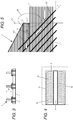
- Figure 5 is an enlarged view of the end of the stringer 2 and the panel 1, the horizontal shading indicating the planes of the plies of fibre-reinforced composite material.
- the panel assembly is manufactured by assembling dry fibre preforms (i.e. carbon fibre without any epoxy resin matrix) then injecting the preforms with epoxy resin matrix material to simultaneously infuse the panel 1 and the stringers 2. This infusion process fully wets the carbon fibre preforms, and the curing of the resin forms bonded joints between the individual plies, and a bonded joint between the stringer 2 and the panel 1 at the stringer/panel interface 10,11.
- the tufts 12 are inserted before the infusion process, so the infusion process fully wets the tufts, and the curing of the resin forms bonds between the tufts and the resin.
- the tufts 12 may be inserted after infusion, or the stringers and panel may be laid up as wet prepreg (resin-impregnated carbon fibre).
- the tufts are distributed in first and second series 12a,b of rows which pass through the first 9a and second 9b foot run-out parts respectively.
- the first series 12a has twenty-one rows
- the second series 12b also has twenty-one rows.
- Each series 12a,b includes an end row nearest to the tip 6 of the stringer foot and twenty further rows spaced progressively further back from the tip of the stringer foot.
- the rows of the first series 12a extend laterally away from the first side 4a of the stringer web towards the first lateral edge
- the rows of the second series 12b extend laterally away from the second side 4b of the stringer web towards the second lateral edge.
- Polygonal curves 14a,b and 15a,b are indicated in Figure 7 for the end rows and one of the further rows, but not for the other rows. Note that the polygonal curves indicated in Figure 7 are constructed from imaginary straight line segments connecting the tufts. So the straight line segments shown in Figure 7 do not indicate seams between the tufts (although optionally there may be seams which follow these lines). Note that the corner of each foot run-out part 9a,b next to the tip 6 is free of tufts.
- each row has the same number of tufts so the centre-to-centre pitch P does not vary from row-to-row.
- the number of tufts per row may increase from row-to-row away from the tip 6, so the centre-to-centre pitch P decreases from row-to-row.
- Each polygonal curve has a "C" shape with a convex side facing the tip 6 of the stringer foot and a concave side facing away from the tip 6 of the stringer foot.
- Each polygonal curve may have a portion where adjacent line segments are co-linear, that is, they lie in a straight line.
- the polygonal curve 14a includes two adjacent line segments which are co-linear. However, none of the polygonal curves are entirely straight.
- FIGs 8-11 The distribution pattern for the tufts 12 is determined in a design phase shown in Figures 8-11.
- Figures 8 and 9 illustrate a failure test of a test specimen with the same structure as the panel assembly of Figure 1 , except with only a single stringer.
- the test specimen is stressed by applying a tensile force indicated by arrows, the size of the arrows in Figures 8 and 9 indicating the size of the force.
- the tensile force is applied by holding the panel and stringer at one end, and holding just the panel at the other end.
- the force is increased in a series of equal steps.
- Figure 8 shows the test specimen at the end of a first step, when a crack has formed at the tip 6 of the stringer foot and propagated along the length of the stringer 2 to the position indicated 15a.
- tufts 12 are inserted through the foot run-out interface in the distribution pattern of Figure 7 , using the series of rows of data points from the design phase as a guide to determine the distribution pattern.
- each tuft 12 has a first (upper) portion 121 in the foot run-out 9a,b and a second (lower) portion 122 in the panel 1.
- the tufts are inclined in a direction of inclination which is away from the tip 6 of the stringer foot, so that the first portion 121 is further from the tip 6 of the stringer foot than the second portion 122.
- the direction of inclination of the tufts is also parallel with the lengthwise direction as shown in Figure 12 .
- Each arrow in Figure 12 indicates a tuft, with the arrow head showing the direction of inclination. So as shown in Figure 12 all of the tufts are inclined directly away from the tip 6 of the stringer foot in the lengthwise direction.
- Figure 13 shows an alternative embodiment in which the tufts are inclined in the opposite direction, towards the tip 6 of the stringer foot.
- Figures 16 and 17 illustrate the difference between the angle of inclination and the angle of azimuth for the tufts.
- Figure 16 shows a tuft 12a angled away from the stringer tip as in Figure 12 , and a tuft 12b angled towards the stringer tip as in Figure 13 .
- the orthogonal projection of the tuft onto the plane of the foot run-out interface 11 is parallel with the lengthwise direction, so the angle of azimuth relative to the lengthwise direction is zero.
- Figure 17 shows a first tuft 12c angled away from the stringer tip with an angle of inclination ⁇ 1, and a second tuft 12d angled towards the stringer tip with an angle of inclination ⁇ 2.
- the orthogonal projection of each tuft onto the plane of the foot run-out interface 11 is not parallel with the lengthwise direction. Rather the orthogonal projection of the first tuft 12c defines an angle of azimuth ⁇ 1 relative to the lengthwise direction, and the orthogonal projection of the second tuft 12d defines an angle of azimuth ⁇ 2 relative to the lengthwise direction.
- half of the tufts have an angle of azimuth ⁇ of +45°, and the other half of the tufts have an angle of azimuth ⁇ of -45°.
- Deformation around the run-out is highly dependent on the geometrical features which lead to formation of the crack and the crack growth. Based on the geometry and the loads, peak tensile and shear stresses are developed at the tip of the run-out or at the crack front after formation of the crack.
- peak tensile and shear stresses are developed at the tip of the run-out or at the crack front after formation of the crack.
- the tufts When vertical tufts are placed behind the crack front (supposing the crack has formed and passed through the tufts) then the tufts reduce the through-thickness tensile stress at the crack tip. However, they do not significantly affect the transverse shear stress. Inclining the tufts behind the crack front considerably reduces the peak tensile and the shear stresses at the crack tip.
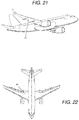
- Figures 21 and 22 show an aircraft with a pair of wings. Each wing has an upper (low pressure) skin 30 and a lower (high pressure) skin 31.
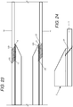
- Figure 23 is a schematic sectional view through one of the aircraft wings showing only the upper and lower skins 30, 31. Each skin comprises a panel assembly as shown in Figures 1-5 , so it will not be described again in detail.
- the wing is attached to the fuselage at its root, and extends in a spanwise direction to its tip.
- the stringers extend in the spanwise direction from an inboard end at the root of the wing to an outboard end towards the tip of the wing.
- Figure 23 shows only the outboard end of the stringer 2.
- the inboard end of the stringer typically has a different construction, running into the wing root joint and being held down by cleats for example.
Landscapes
- Engineering & Computer Science (AREA)
- Mechanical Engineering (AREA)
- Aviation & Aerospace Engineering (AREA)
- Chemical & Material Sciences (AREA)
- Composite Materials (AREA)
- Moulding By Coating Moulds (AREA)
- Working Measures On Existing Buildindgs (AREA)
Abstract
Description
- The present invention relates to a panel assembly, typically but not exclusively for a composite skin of an aircraft wing.
- The design of stringer run-outs in composite skins of aircraft wings presents a great technical challenge. High shear and peel stresses can develop locally at the run-out causing the stringer to peel off from the skin. Out of plane stresses develop at the tip of the run-out and since composites are poor in out-of-plane strength, cracks are prone to form at the tip. Additionally, composites are poor in Mode-1 fracture toughness, so these cracks may grow.
- A known solution is to clamp the run-out to the skin with a metallic finger plate which is bolted to the stringer foot and skin, as disclosed in
US2013/0313391 . - A first aspect of the invention provides a panel assembly comprising: a panel; a stringer comprising a stringer foot and an upstanding stringer web, wherein the stringer foot comprises a flange which extends in a widthwise direction between the stringer web and a lateral edge and in a lengthwise direction alongside the stringer web, and a foot run-out which extends between the flange and a tip of the stringer foot, wherein the foot run-out is bonded to the panel at a foot run-out interface; and reinforcement elements which pass through the foot run-out interface, wherein the reinforcement elements are distributed across the foot run-out interface in a series of rows including an end row nearest to the tip of the stringer foot and further rows spaced progressively further from the tip of the stringer foot, and at least the end row comprises three or more of the reinforcement elements which are distributed along a polygonal curve.
- A polygonal curve is a series of line segments connected by corners, where not all of the line segments are co-linear - in other words they do not all lie in a straight line. Distributing the end row along a polygonal curve rather than a straight line enables the reinforcement elements to be more equally loaded by following the expected line of a curved crack front, thus avoiding successive failure of the reinforcement elements.
- A further aspect of the invention provides a method of reinforcing a panel assembly, the panel assembly comprising: a panel; a stringer comprising a stringer foot and an upstanding stringer web, wherein the stringer foot comprises a flange which extends in a widthwise direction between the stringer web and a lateral edge and in a lengthwise direction alongside the stringer web, and a foot run-out which extends between the flange and a tip of the stringer foot, wherein the foot run-out contacts the panel at a foot run-out interface. The method comprises: in a design phase, performing a failure test of a test specimen or a failure analysis of a computer model to obtaining a series of rows of points each corresponding with a respective crack profile; and in a reinforcement phase, inserting reinforcement elements through the foot run-out interface in a distribution pattern, and using the series of rows of points from the design phase to determine the distribution pattern of the reinforcement elements across the foot run-out interface. Optionally the distribution pattern comprises a series of rows including an end row nearest to the tip of the stringer foot and further rows spaced progressively further from the tip of the stringer foot, and at least the end row comprises three or more of the reinforcement elements which are distributed along a polygonal curve.
- Optionally the end row comprises four, five, six or more of the reinforcement elements which are distributed along a polygonal curve. Providing a larger number of reinforcement elements in the end row enables the polygonal curve to more closely follow the profile of a tightly curved crack front.
- Preferably at least some of the further rows comprise three, four, five, six or more of the reinforcement elements which are distributed along a respective polygonal curve. Providing a larger number of reinforcement elements in the further rows enables each polygonal curve to more closely follow the profile of a tightly curved crack front. Optionally at least some of the further rows have more reinforcement elements than the end row.
- Preferably the series of rows do not form a rectilinear grid, or any other grid of identical polygons.
- Optionally the polygonal curve, or each respective polygonal curve, has a convex side facing the tip of the stringer foot and a concave side facing away from the tip of the stringer foot.
- Optionally at least some of the reinforcement elements are inclined relative to the foot run-out interface. Preferably at least some of the reinforcement elements are inclined at an oblique angle of inclination relative to the foot run-out interface and in a direction of inclination which is either towards or away from the tip of the stringer foot and defines an angle of azimuth relative to the lengthwise direction, and the angle of azimuth lies between -45° and +45°.
- Preferably the reinforcement elements are bonded to the foot run-out and/or the panel. This enhances the mechanical performance of the reinforcement elements, prevents leakage problems associated with bolts, and also avoids the structural weakness and lightning strike problems associated with drilled bolt holes.
- Preferably each reinforcement element has a diameter less than 1mm or less than 2mm.
- The reinforcement elements of the end row may be spaced apart along the polygonal curve with a centre-to-centre pitch which is substantially constant, or varies by no more than 10% or 20% from an average centre-to-centre pitch of the end row.
- Preferably the reinforcement elements of the end row are spaced apart along the polygonal curve with an average centre-to-centre pitch which is less than 10mm or less than 5mm.
- Preferably the rows are spaced apart with an average row-to-row pitch which is less than 10mm or less than 5mm.
- By way of example, the reinforcement elements may be tufts, Z-pins, or fasteners such as bolts or rivets.
- Preferably the foot run-out comprises multiple plies (typically fibre-reinforced composite plies); and the reinforcement elements pass through some or all of the plies of the foot run-out.
- Preferably the panel comprises multiple plies (typically fibre-reinforced composite plies); and the reinforcement elements pass through some or all of the plies of the panel.
- Preferably the foot run-out and/or the panel are made from a fibre-reinforced composite material.
- Preferably the panel has a thickness at the foot run-out interface, and at least some of the reinforcement elements are spaced from the tip of the stringer foot at the point of passing through the foot run-out interface by a distance less than the thickness of the panel at the foot run-out interface.
- Preferably at least some of the reinforcement elements are spaced from the tip of the stringer foot at the point of passing through the foot run-out interface by a distance less than 10mm or less than 5mm.
- The stringer web may have the same height along the entire length of the stringer, but more typically it comprises a web run-out which upstands by a height from the stringer foot and terminates at a tip of the stringer web, the height of the web run-out reduces towards the tip of the stringer web, and the foot run-out coincides with the web run-out.
- The stringer may have a variety of cross-sectional shapes, including T-shaped, L-shaped, omega (or top-hat) shaped, or J-shaped.
- The web may stop short of the foot run-out, so the foot run-out extends further than the web in the lengthwise direction. Alternatively the web may terminate in the same plane as the tip of the foot run-out.
- Optionally the foot run-out comprises a first foot run-out flange which extends in the widthwise direction between a first side of the stringer web and a first lateral edge and a second foot run-out flange which extends in the widthwise direction between a second side of the stringer web opposite the first side of the stringer web and a second lateral edge, the reinforcement elements are distributed in first and second series of rows which pass through the first and second foot run-out flanges respectively, each row including an end row nearest the tip of the stringer foot and further rows spaced progressively further from the tip of the stringer foot, the rows of the first series extend laterally away from the first side of the stringer web towards the first lateral edge, the rows of the second series extend laterally away from the second side of the stringer web towards the second lateral edge, the end row of the first series comprises three or more of the reinforcement elements which are distributed along a first polygonal curve, and the end row of the second series comprises three or more of the reinforcement elements which are distributed along a second polygonal curve.
- Embodiments of the invention will now be described with reference to the accompanying drawings, in which:
-
Figure 1 is a plan view of a panel assembly; -
Figure 2 is a sectional side view of the panel assembly ofFigure 1 ; -
Figure 3 is a sectional end view of the panel assembly ofFigure 1 showing multiple stringers; -
Figure 4 is an enlarged plan view of the stringer run-out; -
Figure 5 is an enlarged sectional side of the of the stringer run-out; -
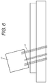
Figure 6 is a schematic view of a tufting head inserting tufts; -
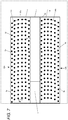
Figure 7 is an enlarged plan view of the stringer run-out; -
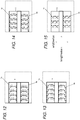
Figures 8-11 are plan views of a test specimen showing crack profiles and data points; -
Figure 12 is a plan view of a stringer run-out with tufts inclined directly away from the tip of the stringer; -
Figure 13 is a plan view of a stringer run-out with tufts inclined directly towards the tip of the stringer; -
Figure 14 is a plan view of a stringer run-out with tufts inclined in alternating directions; -
Figure 15 is a plan view of a stringer run-out with tufts inclined towards the tip of the stringer with an angle of azimuth of +/-45°; -
Figure 16 shows two tufts inclined with an angle of azimuth of 0°; -
Figure 17 shows two tufts inclined with different angles of inclination and different angles of azimuth; -
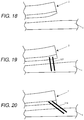
Figure 18 is a sectional side view of a stringer and panel with no tufts, showing the deformation of the stringer and panel predicted by a finite element analysis (FEA) model; -
Figure 19 is a sectional side view of a stringer and panel with vertical tufts; -
Figure 20 is a sectional side view of a stringer and panel with inclined tufts; -
Figures 21 and 22 show an aircraft; -
Figure 23 is a sectional side view showing the upper and lower skins of one of the aircraft wings; and -
Figure 24 shows a tuft with non-protruding ends. - A panel assembly shown in
Figures 1-5 comprises apanel 1 carryingmultiple stringers 2. Only one of the stringers is shown inFigure 1 , but three of the stringers are shown side-by-side inFigure 3 . All of the stringers are similar, so only thestringer 2 shown inFigure 1 will be described in detail. - The
stringer 2 has a T-shaped cross-section as shown inFigure 3 , with a stringer foot and anupstanding stringer web 4. Thestringer web 4 upstands by a maximum height H from the stringer foot as shown inFigure 2 and3 . At the end of thestringer web 4 there is a web run-out 8 which terminates at atip 7. The web run-out 8 tapers so that the height of the web run-out 8 reduces towards thetip 7 as shown inFigure 2 . - The stringer foot has two symmetrical halves: a
flange 3a and foot run-outpart 9a on one side of the web; and aflange 3b and foot run-outpart 9b on the other side of the web. The majority of the stringer foot comprises theflanges 3a,b which each extend in a widthwise direction between thestringer web 4 and a respectivelateral edge 5a,b. Eachflange 3a,b also extends in a lengthwise direction alongside thestringer web 4 up to a respective foot run-outpart 9a,b which coincides with the tapering web run-out 8. The foot run-outparts 9a,b each extend in the lengthwise direction between arespective flange 3a,b and atip 6 of the stringer foot. Thetip 6 of the stringer foot is a straight edge running in the widthwise direction perpendicular to the lengthwise direction, although other geometries may be possible. The first foot run-outpart 9a extends in the widthwise direction between afirst side 4a of the stringer web and a first lateral edge, and the second foot run-outpart 9b extends in the widthwise direction between asecond side 4b of the stringer web opposite thefirst side 4a of the stringer web and a second lateral edge. In this example thetip 7 of the web and thetip 6 of the stringer foot all lie in thesame tip plane 6a perpendicular to the lengthwise direction. -
Figure 1 shows only one end of thestringer 2. The opposite end of the stringer may be similar, or different to the end of the stringer shown inFigure 1 . Theflanges 3a,b run along the full length of the stringer between the foot run-outparts 9a,b and the opposite end of the stringer. Thestringer foot flange interface 10 where theflanges 3a,b are bonded to the panel, and a foot run-out interface 11 where the foot run-outparts 9a,b are bonded to the panel. - The
panel 1 and thestringer 2 are both made from fibre-reinforced composite materials. More specifically - thepanel 1 comprises multiple plies of fibre-reinforced composite material, such as carbon fibres impregnated or infused with an epoxy resin matrix. Thestringer 2 is typically made from a similar (or the same) composite material. That is, thestringer foot stringer web 4 are made from multiple plies of fibre-reinforced composite material, such as carbon fibres impregnated or infused with an epoxy resin matrix. Although the stringer foot is illustrated schematically inFigure 3 as separate from thestringer web 4, in a preferred embodiment thestringer 2 is constructed as two back-to-back L-section pieces - as shown inFig 1 ofUS5827383 for example.Figure 5 is an enlarged view of the end of thestringer 2 and thepanel 1, the horizontal shading indicating the planes of the plies of fibre-reinforced composite material. The panel assembly is manufactured by assembling dry fibre preforms (i.e. carbon fibre without any epoxy resin matrix) then injecting the preforms with epoxy resin matrix material to simultaneously infuse thepanel 1 and thestringers 2. This infusion process fully wets the carbon fibre preforms, and the curing of the resin forms bonded joints between the individual plies, and a bonded joint between thestringer 2 and thepanel 1 at the stringer/panel interface -
Reinforcement elements 12, shown in detail inFigure 5 , pass through the full thickness of the stringer foot and the full thickness of thepanel 1. In a preferred embodiment eachreinforcement element 12 is a tuft - that is, a loop of fibre such as carbon-fibre. Theindividual tufts 12 may be connected to adjacent tufts by seams, or more typically they are independent with no seams. In other embodiments thereinforcement elements 12 may be Z-pins made of carbon-fibre, steel, copper or any other suitable material. In the following description thereinforcement elements 12 will be referred to as tufts. -
Figure 6 is a schematic view of a tufting head 13 inserting thetufts 12. The tufts are inserted simultaneously, each tuft being inserted by a respective needle inclined at the necessary angle and direction of inclination. An imprint of the required tufting parameters (angle, pattern, density, and profile) is defined in the tufting head 13. - The
tufts 12 are inserted before the infusion process, so the infusion process fully wets the tufts, and the curing of the resin forms bonds between the tufts and the resin. Alternatively, thetufts 12 may be inserted after infusion, or the stringers and panel may be laid up as wet prepreg (resin-impregnated carbon fibre). - As shown in
Figure 7 , thetufts 12 are distributed across the full extent of the foot run-outparts 9a,b and also across part of theflanges 3a,b. As shown inFigure 5 , the tufts pass through the foot run-out interface 11 from the foot run-outparts 9a,b into thepanel 1. A small number of the tufts are also inserted into theflanges 3a,b - these tufts passing through theflange interface 10 between the flanges and the panel. The rest of each flange is free of tufts as shown inFigure 2 . In other examples, the tufts may only cover part of the foot run-outparts 9a,b. - The tufts are distributed in first and
second series 12a,b of rows which pass through the first 9a and second 9b foot run-out parts respectively. Thefirst series 12a has twenty-one rows, and thesecond series 12b also has twenty-one rows. Eachseries 12a,b includes an end row nearest to thetip 6 of the stringer foot and twenty further rows spaced progressively further back from the tip of the stringer foot. As indicated inFigure 7 , the rows of thefirst series 12a extend laterally away from thefirst side 4a of the stringer web towards the first lateral edge, and the rows of thesecond series 12b extend laterally away from thesecond side 4b of the stringer web towards the second lateral edge. The end row of thefirst series 12a consists of six tufts which are distributed along a firstpolygonal curve 14a which is not a straight line, and the end row of thesecond series 12b consists of six tufts which are distributed along a secondpolygonal curve 14b which is also not a straight line. - Polygonal curves 14a,b and 15a,b are indicated in
Figure 7 for the end rows and one of the further rows, but not for the other rows. Note that the polygonal curves indicated inFigure 7 are constructed from imaginary straight line segments connecting the tufts. So the straight line segments shown inFigure 7 do not indicate seams between the tufts (although optionally there may be seams which follow these lines). Note that the corner of each foot run-outpart 9a,b next to thetip 6 is free of tufts. - In this example each row consists of six tufts, but in other embodiments there may be more tufts (for instance sixteen per row) or fewer tufts (for instance three, four or five per row). The centre-to-centre pitch between the adjacent tufts in each row does not vary substantially along each row. In this example the average centre-to-centre pitch (labelled P in
Figure 7 ) along a row is 3.5mm and the diameter of each tuft is 0.5mm. The centre-to-centre pitch may vary slightly either side of the average along a row, but preferably by no more than 20% (0.7mm). The centre-to-centre pitch between rows is also approximately 3.5 mm. - In this example, each row has the same number of tufts so the centre-to-centre pitch P does not vary from row-to-row. In another example, the number of tufts per row may increase from row-to-row away from the
tip 6, so the centre-to-centre pitch P decreases from row-to-row. - Each polygonal curve has a "C" shape with a convex side facing the
tip 6 of the stringer foot and a concave side facing away from thetip 6 of the stringer foot. Each polygonal curve may have a portion where adjacent line segments are co-linear, that is, they lie in a straight line. For instance, thepolygonal curve 14a includes two adjacent line segments which are co-linear. However, none of the polygonal curves are entirely straight. - The distribution pattern for the
tufts 12 is determined in a design phase shown inFigures 8-11. Figures 8 and 9 illustrate a failure test of a test specimen with the same structure as the panel assembly ofFigure 1 , except with only a single stringer. The test specimen is stressed by applying a tensile force indicated by arrows, the size of the arrows inFigures 8 and 9 indicating the size of the force. The tensile force is applied by holding the panel and stringer at one end, and holding just the panel at the other end. The force is increased in a series of equal steps.Figure 8 shows the test specimen at the end of a first step, when a crack has formed at thetip 6 of the stringer foot and propagated along the length of thestringer 2 to the position indicated 15a. A smallultrasonic probe 18 is scanned across the back of thepanel 1. An ultrasonic signal is transmitted through the test specimen and echo signals are received. Diminished strength of the echo signal at a particular location defines the presence of a crack (or start of the crack front). The crack locations are marked on the test specimen to obtain a first pair of rows ofdata points 16a,b shown inFigure 10 corresponding with the crack profile ofFigure 8 . An approximate smooth curve over the data points is drawn to represent the crack front. Then the force is increased so that the crack moves to the position indicated inFigure 9 at 15b. Theultrasonic inspection device 18 is scanned again across the foot run-outparts 9a,b to obtain a second pair of rows ofdata points 17a,b shown inFigure 11 corresponding with the crack profile ofFigure 9 . The process is repeated to obtain a full set of data points. - After the design phase of
Figures 8-11 , in a reinforcement phase thetufts 12 are inserted through the foot run-out interface in the distribution pattern ofFigure 7 , using the series of rows of data points from the design phase as a guide to determine the distribution pattern. - In another embodiment, during the design phase, a finite element analysis (FEA) is performed on a computer model of the assembly (consisting of the stringer, panel, run-out and tufts) to theoretically predict the crack profile and number of tufts needed in each row to contain the crack growth. This analysis is performed by a suitably programmed computer to obtain the series of rows of
data points 16a,b;17a,b each row corresponding with a respective theoretical crack profile. - As shown in
Figure 5 , the tufts are inclined at an oblique angle of inclination θ relative to the foot run-out interface 11, in this case about 45° although this angle may vary. Eachtuft 12 has a first (upper)portion 121 in the foot run-out 9a,b and a second (lower)portion 122 in thepanel 1. The tufts are inclined in a direction of inclination which is away from thetip 6 of the stringer foot, so that thefirst portion 121 is further from thetip 6 of the stringer foot than thesecond portion 122. The direction of inclination of the tufts is also parallel with the lengthwise direction as shown inFigure 12 . Each arrow inFigure 12 indicates a tuft, with the arrow head showing the direction of inclination. So as shown inFigure 12 all of the tufts are inclined directly away from thetip 6 of the stringer foot in the lengthwise direction. -
Figure 13 shows an alternative embodiment in which the tufts are inclined in the opposite direction, towards thetip 6 of the stringer foot. -
Figure 14 shows a further alternative embodiment in which columns of tufts are inclined in alternating senses, towards and away from thetip 6 of the stringer foot. -
Figure 15 shows a further alternative embodiment in which the tufts are inclined towards thetip 6 of the stringer foot, but the direction of inclination is not parallel with the lengthwise direction but rather defines an angle of azimuth of +/- 45°. In another embodiment, the arrows inFigure 15 could be reversed so that the tufts are inclined away from thetip 6 of the stringer foot. -
Figures 16 and 17 illustrate the difference between the angle of inclination and the angle of azimuth for the tufts.Figure 16 shows atuft 12a angled away from the stringer tip as inFigure 12 , and atuft 12b angled towards the stringer tip as inFigure 13 . In each case the orthogonal projection of the tuft onto the plane of the foot run-out interface 11 is parallel with the lengthwise direction, so the angle of azimuth relative to the lengthwise direction is zero. -
Figure 17 shows afirst tuft 12c angled away from the stringer tip with an angle of inclination θ1, and asecond tuft 12d angled towards the stringer tip with an angle of inclination θ2. In this case the orthogonal projection of each tuft onto the plane of the foot run-out interface 11 is not parallel with the lengthwise direction. Rather the orthogonal projection of thefirst tuft 12c defines an angle of azimuth α1 relative to the lengthwise direction, and the orthogonal projection of thesecond tuft 12d defines an angle of azimuth α2 relative to the lengthwise direction. In the case ofFigure 15 , half of the tufts have an angle of azimuth α of +45°, and the other half of the tufts have an angle of azimuth α of -45°. - In the case of
Figures 12 and 13 , the angle of azimuth is shown as precisely zero, but in practice manufacturing tolerances will mean that the angle of azimuth of each tuft may deviate from zero by up to 5°, 10° or 15°. However, as long as the angle of azimuth is sufficiently low then the inclined tufts will be sufficiently aligned with the lengthwise direction to provide advantages compared with vertical tufts. - Deformation around the run-out is highly dependent on the geometrical features which lead to formation of the crack and the crack growth. Based on the geometry and the loads, peak tensile and shear stresses are developed at the tip of the run-out or at the crack front after formation of the crack. When vertical tufts are placed behind the crack front (supposing the crack has formed and passed through the tufts) then the tufts reduce the through-thickness tensile stress at the crack tip. However, they do not significantly affect the transverse shear stress. Inclining the tufts behind the crack front considerably reduces the peak tensile and the shear stresses at the crack tip.
-
Figure 18 is a view of astringer 2 andpanel 1 with no tufts, showing the deformation of the stringer and panel predicted by a finite element analysis (FEA) model after a crack has propagated between them. Note that there is a distinct upward kink at the tip of thestringer 2.Figure 19 shows the output of the same FEA model but withvertical tufts 123. Note that the kink is still present.Figure 20 shows the output of the same FEA model but withtufts 124 inclined away from the tip of the stringer. Note that there is no kink in the stringer run-out. This relative lack of deformation of the stringer run-out is beneficial because it reduces tensile and shear stresses at the crack front. - The inclined tufts modify the local load path as shown in
Figure 5 - the arrows indicating the load path from thepanel 1 to thestringer 2 via the inclined tufts. This results in reduced load flow in alocal zone 20 at the tip of the stringer minimising the chance of formation of a crack in this local zone. Calculations show that for a tufting density of 4%, the shear stiffness of the joint is doubled for tufts inclined at 45° in the region that is still bonded, which will alleviate the transverse shear stresses at the crack front or at the tip of the run-out before a crack is formed, thereby reducing the chance of a crack spreading by shear, or even forming in the first place. Beneficially, the first row of inclined tufts is sufficiently close to thetip 6 that they extend through theplane 6a of the tip as shown inFigure 5 . - The first row of tufts is positioned as close as possible to the
tip 6 of the stringer foot, in order to provide this reduced load flow in thelocal zone 20. In the case ofFigure 5 , the distance D between the first row of tufts and thetip 6 of the foot run-out, at the point where the tuft passes through theinterface 11, is less than the thickness of thepanel 1 at theinterface 11. The thickness of thepanel 1 at theinterface 11 could vary - for example it might be between 3mm and 10mm. Typically the distance D is greater than 3.5mm but less than 10mm. -
Figures 21 and 22 show an aircraft with a pair of wings. Each wing has an upper (low pressure)skin 30 and a lower (high pressure)skin 31.Figure 23 is a schematic sectional view through one of the aircraft wings showing only the upper andlower skins Figures 1-5 , so it will not be described again in detail. The wing is attached to the fuselage at its root, and extends in a spanwise direction to its tip. The stringers extend in the spanwise direction from an inboard end at the root of the wing to an outboard end towards the tip of the wing.Figure 23 shows only the outboard end of thestringer 2. The inboard end of the stringer typically has a different construction, running into the wing root joint and being held down by cleats for example. - The aerodynamic loads acting on the wing cause it to bend upwards so the lower skin is in tension. Therefore in the
lower skin 31 the tufts are inclined in a direction of inclination which is away from the tip of the stringer foot. So the first (upper)portion 121 of each tuft in the stringer foot is further from thetip 6 of the stringer foot than the second (lower)portion 122 of the tuft in thelower skin 31. - The upward bending of the wing causes the
upper skin 30 to be in compression, so the direction of inclination of the tufts is reversed compared with the lower skin. So in the upper skin the tufts are inclined in a direction of inclination which is towards thetip 6 of the stringer foot, so that the first (lower)portion 121 of each tuft in the stringer foot is closer to thetip 6 of the stringer foot than the second (upper)portion 122 of the tuft in theupper skin 30. - The ends of the tufts in
Figures 1-23 are shown protruding from the composite structure. In some applications this may be acceptable, but in the case of an aircraft wing as inFigure 23 , ideally the end of each tuft is bent so as to be flush with the surface, as shown by thesingle tuft 19 inFigure 24 . This is particularly important on the outer aerodynamic surface of the wing skin. - Where the word 'or' appears this is to be construed to mean 'and/or' such that items referred to are not necessarily mutually exclusive and may be used in any appropriate combination.
- Although the invention has been described above with reference to one or more preferred embodiments, it will be appreciated that various changes or modifications may be made without departing from the scope of the invention as defined in the appended claims.
Claims (15)
- A panel assembly comprising:a panel;a stringer comprising a stringer foot and an upstanding stringer web, wherein the stringer foot comprises a flange which extends in a widthwise direction between the stringer web and a lateral edge and in a lengthwise direction alongside the stringer web, and a foot run-out which extends between the flange and a tip of the stringer foot, wherein the foot run-out is bonded to the panel at a foot run-out interface; andreinforcement elements which pass through the foot run-out interface,wherein the reinforcement elements are distributed across the foot run-out interface in a series of rows including an end row nearest to the tip of the stringer foot and further rows spaced progressively further from the tip of the stringer foot, and at least the end row comprises three or more of the reinforcement elements which are distributed along a polygonal curve.
- The panel assembly of claim 1 wherein the reinforcement elements are bonded to the foot run-out and/or the panel.
- The panel assembly of any preceding claim wherein at least the end row comprises four, five, six or more of the reinforcement elements which are distributed along the polygonal curve.
- The panel assembly of any preceding claim wherein at least some of the further rows comprise three or more of the reinforcement elements which are distributed along a respective polygonal curve.
- The panel assembly of any preceding claim wherein at least some of the further rows comprise four, five, six or more of the reinforcement elements which are distributed along a respective polygonal curve.
- The panel assembly of any preceding claim wherein the series of rows do not form a rectilinear grid or a grid of identical polygons.
- The panel assembly of any preceding claim wherein the reinforcement elements of the end row are spaced apart along the polygonal curve with a centre-to-centre pitch which is substantially constant, or varies by no more than 10% or 20% from an average centre-to-centre pitch of the end row.
- The panel assembly of any preceding claim wherein the polygonal curve, or each respective polygonal curve, has a convex side facing the tip of the stringer foot and a concave side facing away from the tip of the stringer foot.
- The panel assembly of any preceding claim wherein each of the reinforcement elements has a diameter less than 2mm.
- The panel assembly of any preceding claim wherein the foot run-out comprises multiple plies; and the reinforcement elements pass through some or all of the plies of the foot run-out.
- The panel assembly of any preceding claim wherein the panel comprises multiple plies; and the reinforcement elements pass through some or all of the plies of the panel.
- The panel assembly of any preceding claim wherein the panel has a thickness at the foot run-out interface, and at least some of the reinforcement elements are spaced from the tip of the stringer foot at the point of passing through the foot run-out interface by a distance less than the thickness of the panel at the foot run-out interface.
- The panel assembly of any preceding claim wherein the foot run-out comprises a first foot run-out flange which extends in the widthwise direction between a first side of the stringer web and a first lateral edge, and a second foot run-out flange which extends in the widthwise direction between a second side of the stringer web opposite the first side of the stringer web and a second lateral edge, the reinforcement elements are distributed in first and second series of rows which pass through the first and second foot run-out flanges respectively, each row including an end row nearest the tip of the stringer foot and further rows spaced progressively further from the tip of the stringer foot, the rows of the first series extend laterally away from the first side of the stringer web towards the first lateral edge, the rows of the second series extend laterally away from the second side of the stringer web towards the second lateral edge, the end row of the first series comprises three or more of the reinforcement elements which are distributed along a first polygonal curve, and the end row of the second series comprises three or more of the reinforcement elements which are distributed along a second polygonal curve.
- An aircraft comprising a panel assembly according to any preceding claim.
- A method of reinforcing a panel assembly, the panel assembly comprising: a panel; a stringer comprising a stringer foot and an upstanding stringer web, wherein the stringer foot comprises a flange which extends in a widthwise direction between the stringer web and a lateral edge and in a lengthwise direction alongside the stringer web, and a foot run-out which extends between the flange and a tip of the stringer foot, wherein the foot run-out contacts the panel at a foot run-out interface, the method comprising:in a design phase, performing a failure test of a test specimen or a failure analysis of a computer model to obtaining a series of rows of points each corresponding with a respective crack profile; andin a reinforcement phase, inserting reinforcement elements through the foot run-out interface in a distribution pattern, and using the series of rows of points from the design phase to determine the distribution pattern of the reinforcement elements across the foot run-out interface.
Applications Claiming Priority (1)
| Application Number | Priority Date | Filing Date | Title |
|---|---|---|---|
| GB1712913.1A GB2565350A (en) | 2017-08-11 | 2017-08-11 | Panel assembly |
Publications (2)
| Publication Number | Publication Date |
|---|---|
| EP3441299A1 true EP3441299A1 (en) | 2019-02-13 |
| EP3441299B1 EP3441299B1 (en) | 2021-05-05 |
Family
ID=59895875
Family Applications (1)
| Application Number | Title | Priority Date | Filing Date |
|---|---|---|---|
| EP18186317.6A Active EP3441299B1 (en) | 2017-08-11 | 2018-07-30 | Panel assembly |
Country Status (4)
| Country | Link |
|---|---|
| US (1) | US11124284B2 (en) |
| EP (1) | EP3441299B1 (en) |
| CN (1) | CN109383751A (en) |
| GB (1) | GB2565350A (en) |
Citations (6)
| Publication number | Priority date | Publication date | Assignee | Title |
|---|---|---|---|---|
| US3837985A (en) * | 1972-02-24 | 1974-09-24 | Whittaker Corp | Multi-directional reinforced composite and method of making the same |
| US4350728A (en) * | 1980-10-02 | 1982-09-21 | The United States Of America As Represented By The Secretary Of The Navy | Cross reinforcement in a graphite-epoxy laminate |
| US20120234978A1 (en) * | 2011-03-14 | 2012-09-20 | Airbus Operations S.L. | Load transfer devices at a stringer run-out |
| US20130313391A1 (en) * | 2012-05-28 | 2013-11-28 | Airbus Operations Limited | Securing plate and aircraft structure |
| WO2014065719A1 (en) * | 2012-10-22 | 2014-05-01 | Saab Ab | Integral attachment of fiber reinforced plastic rib to fiber reinforced plastic skin for aircraft airfoils |
| US20140250665A1 (en) * | 2011-10-07 | 2014-09-11 | Korea Aerospace Research Institute | Z-pin patch and method for manufacturing or coupling a composite laminated structure using same |
Family Cites Families (16)
| Publication number | Priority date | Publication date | Assignee | Title |
|---|---|---|---|---|
| US4109435A (en) * | 1977-08-26 | 1978-08-29 | Rockwell International Corporation | Composite structural joint and method of fabrication thereof |
| US5466506A (en) * | 1992-10-27 | 1995-11-14 | Foster-Miller, Inc. | Translaminar reinforcement system for Z-direction reinforcement of a fiber matrix structure |
| US5789061A (en) | 1996-02-13 | 1998-08-04 | Foster-Miller, Inc. | Stiffener reinforced assembly and method of manufacturing same |
| US5876540A (en) * | 1996-05-31 | 1999-03-02 | The Boeing Company | Joining composites using Z-pinned precured strips |
| DE10159067A1 (en) | 2001-12-01 | 2003-06-26 | Daimler Chrysler Ag | Fiber composite crash structure |
| FR2866626B1 (en) * | 2004-02-20 | 2006-05-19 | Airbus France | OFFSET OF STIFF SLITTED SLOPES AND PANEL PROVIDED WITH SUCH A STOP |
| DK176564B1 (en) * | 2004-12-29 | 2008-09-01 | Lm Glasfiber As | Fiber reinforced joint |
| GB0708333D0 (en) | 2007-04-30 | 2007-06-06 | Airbus Uk Ltd | Composite structure |
| GB0819159D0 (en) * | 2008-10-20 | 2008-11-26 | Airbus Uk Ltd | Joint between aircraft components |
| GB201005308D0 (en) * | 2010-03-30 | 2010-05-12 | Airbus Operations Ltd | Composite structural member |
| GB201016279D0 (en) | 2010-09-28 | 2010-11-10 | Airbus Operations Ltd | Stiffener run-out |
| ES2405155B1 (en) * | 2011-10-24 | 2014-09-02 | Airbus Operations S.L. | TERMINATION AREAS OF OPTIMIZED LARGUERILLOS IN AIRCRAFT COMPONENTS |
| US8974886B2 (en) * | 2012-04-25 | 2015-03-10 | The Boeing Company | Disbond resistant composite stiffener runout |
| EP2808156B1 (en) | 2013-05-28 | 2017-07-12 | Airbus Operations GmbH | A shell segment of an aircraft and a production method |
| EP2808147B1 (en) * | 2013-05-30 | 2017-03-01 | Airbus Operations S.L. | Hybrid tool for curing pieces of composite material |
| US9399509B2 (en) * | 2014-04-10 | 2016-07-26 | The Boeing Company | Vent stringer fitting |
-
2017
- 2017-08-11 GB GB1712913.1A patent/GB2565350A/en not_active Withdrawn
-
2018
- 2018-07-30 EP EP18186317.6A patent/EP3441299B1/en active Active
- 2018-08-09 CN CN201810902801.5A patent/CN109383751A/en active Pending
- 2018-08-09 US US16/059,822 patent/US11124284B2/en active Active
Patent Citations (6)
| Publication number | Priority date | Publication date | Assignee | Title |
|---|---|---|---|---|
| US3837985A (en) * | 1972-02-24 | 1974-09-24 | Whittaker Corp | Multi-directional reinforced composite and method of making the same |
| US4350728A (en) * | 1980-10-02 | 1982-09-21 | The United States Of America As Represented By The Secretary Of The Navy | Cross reinforcement in a graphite-epoxy laminate |
| US20120234978A1 (en) * | 2011-03-14 | 2012-09-20 | Airbus Operations S.L. | Load transfer devices at a stringer run-out |
| US20140250665A1 (en) * | 2011-10-07 | 2014-09-11 | Korea Aerospace Research Institute | Z-pin patch and method for manufacturing or coupling a composite laminated structure using same |
| US20130313391A1 (en) * | 2012-05-28 | 2013-11-28 | Airbus Operations Limited | Securing plate and aircraft structure |
| WO2014065719A1 (en) * | 2012-10-22 | 2014-05-01 | Saab Ab | Integral attachment of fiber reinforced plastic rib to fiber reinforced plastic skin for aircraft airfoils |
Also Published As
| Publication number | Publication date |
|---|---|
| US11124284B2 (en) | 2021-09-21 |
| US20190047679A1 (en) | 2019-02-14 |
| GB201712913D0 (en) | 2017-09-27 |
| EP3441299B1 (en) | 2021-05-05 |
| CN109383751A (en) | 2019-02-26 |
| GB2565350A (en) | 2019-02-13 |
Similar Documents
| Publication | Publication Date | Title |
|---|---|---|
| EP2822852B1 (en) | Bonded splice joint | |
| EP2142360B1 (en) | Composite structure comprising a stringer with a pad embedded in the recess of a panel and method of transmitting forces | |
| EP3441303B1 (en) | Panel assembly | |
| EP2730498A2 (en) | Joint for composite wings | |
| CN107757873B (en) | System and method for structurally supporting an aircraft wing | |
| EP2173539B1 (en) | Apparatus and method for forming fibre reinforced composite structures | |
| DK2454473T3 (en) | Device for assembling sections of blades for wind turbines and method for connecting sections of blades for wind turbines | |
| EP2602097A2 (en) | Fiber composite component assembly having at least two plate-shaped composite structures and processes for preparing same | |
| EP2808156B1 (en) | A shell segment of an aircraft and a production method | |
| US11760041B2 (en) | Wind turbine blade manufacture | |
| CA2829899C (en) | Joint for composite wings | |
| EP3321178A1 (en) | Reinforced propeller blade and spar | |
| US11787148B2 (en) | Honeycomb core sandwich panels | |
| EP3441299B1 (en) | Panel assembly | |
| EP2848518B1 (en) | Carbon fiber reinforced polymer cargo beam with integrated cargo stanchions and c-splices | |
| US11685503B2 (en) | Stringer assemblies and methods of forming thereof | |
| Jürgens et al. | Influence of a 3D-Reinforcement Design on the structural Mechanics of co-bonded CFRP-Joints | |
| Overd | Carbon composite repairs of helicopter metallic primary structures |
Legal Events
| Date | Code | Title | Description |
|---|---|---|---|
| PUAI | Public reference made under article 153(3) epc to a published international application that has entered the european phase |
Free format text: ORIGINAL CODE: 0009012 |
|
| STAA | Information on the status of an ep patent application or granted ep patent |
Free format text: STATUS: THE APPLICATION HAS BEEN PUBLISHED |
|
| AK | Designated contracting states |
Kind code of ref document: A1 Designated state(s): AL AT BE BG CH CY CZ DE DK EE ES FI FR GB GR HR HU IE IS IT LI LT LU LV MC MK MT NL NO PL PT RO RS SE SI SK SM TR |
|
| AX | Request for extension of the european patent |
Extension state: BA ME |
|
| STAA | Information on the status of an ep patent application or granted ep patent |
Free format text: STATUS: REQUEST FOR EXAMINATION WAS MADE |
|
| 17P | Request for examination filed |
Effective date: 20190726 |
|
| RBV | Designated contracting states (corrected) |
Designated state(s): AL AT BE BG CH CY CZ DE DK EE ES FI FR GB GR HR HU IE IS IT LI LT LU LV MC MK MT NL NO PL PT RO RS SE SI SK SM TR |
|
| STAA | Information on the status of an ep patent application or granted ep patent |
Free format text: STATUS: EXAMINATION IS IN PROGRESS |
|
| 17Q | First examination report despatched |
Effective date: 20200320 |
|
| GRAP | Despatch of communication of intention to grant a patent |
Free format text: ORIGINAL CODE: EPIDOSNIGR1 |
|
| STAA | Information on the status of an ep patent application or granted ep patent |
Free format text: STATUS: GRANT OF PATENT IS INTENDED |
|
| INTG | Intention to grant announced |
Effective date: 20201127 |
|
| GRAS | Grant fee paid |
Free format text: ORIGINAL CODE: EPIDOSNIGR3 |
|
| GRAA | (expected) grant |
Free format text: ORIGINAL CODE: 0009210 |
|
| STAA | Information on the status of an ep patent application or granted ep patent |
Free format text: STATUS: THE PATENT HAS BEEN GRANTED |
|
| AK | Designated contracting states |
Kind code of ref document: B1 Designated state(s): AL AT BE BG CH CY CZ DE DK EE ES FI FR GB GR HR HU IE IS IT LI LT LU LV MC MK MT NL NO PL PT RO RS SE SI SK SM TR |
|
| REG | Reference to a national code |
Ref country code: GB Ref legal event code: FG4D |
|
| REG | Reference to a national code |
Ref country code: CH Ref legal event code: EP |
|
| REG | Reference to a national code |
Ref country code: AT Ref legal event code: REF Ref document number: 1389503 Country of ref document: AT Kind code of ref document: T Effective date: 20210515 |
|
| REG | Reference to a national code |
Ref country code: IE Ref legal event code: FG4D |
|
| REG | Reference to a national code |
Ref country code: DE Ref legal event code: R096 Ref document number: 602018016513 Country of ref document: DE |
|
| REG | Reference to a national code |
Ref country code: LT Ref legal event code: MG9D |
|
| REG | Reference to a national code |
Ref country code: AT Ref legal event code: MK05 Ref document number: 1389503 Country of ref document: AT Kind code of ref document: T Effective date: 20210505 |
|
| PG25 | Lapsed in a contracting state [announced via postgrant information from national office to epo] |
Ref country code: FI Free format text: LAPSE BECAUSE OF FAILURE TO SUBMIT A TRANSLATION OF THE DESCRIPTION OR TO PAY THE FEE WITHIN THE PRESCRIBED TIME-LIMIT Effective date: 20210505 Ref country code: HR Free format text: LAPSE BECAUSE OF FAILURE TO SUBMIT A TRANSLATION OF THE DESCRIPTION OR TO PAY THE FEE WITHIN THE PRESCRIBED TIME-LIMIT Effective date: 20210505 Ref country code: LT Free format text: LAPSE BECAUSE OF FAILURE TO SUBMIT A TRANSLATION OF THE DESCRIPTION OR TO PAY THE FEE WITHIN THE PRESCRIBED TIME-LIMIT Effective date: 20210505 Ref country code: AT Free format text: LAPSE BECAUSE OF FAILURE TO SUBMIT A TRANSLATION OF THE DESCRIPTION OR TO PAY THE FEE WITHIN THE PRESCRIBED TIME-LIMIT Effective date: 20210505 Ref country code: BG Free format text: LAPSE BECAUSE OF FAILURE TO SUBMIT A TRANSLATION OF THE DESCRIPTION OR TO PAY THE FEE WITHIN THE PRESCRIBED TIME-LIMIT Effective date: 20210805 |
|
| PG25 | Lapsed in a contracting state [announced via postgrant information from national office to epo] |
Ref country code: LV Free format text: LAPSE BECAUSE OF FAILURE TO SUBMIT A TRANSLATION OF THE DESCRIPTION OR TO PAY THE FEE WITHIN THE PRESCRIBED TIME-LIMIT Effective date: 20210505 Ref country code: PL Free format text: LAPSE BECAUSE OF FAILURE TO SUBMIT A TRANSLATION OF THE DESCRIPTION OR TO PAY THE FEE WITHIN THE PRESCRIBED TIME-LIMIT Effective date: 20210505 Ref country code: PT Free format text: LAPSE BECAUSE OF FAILURE TO SUBMIT A TRANSLATION OF THE DESCRIPTION OR TO PAY THE FEE WITHIN THE PRESCRIBED TIME-LIMIT Effective date: 20210906 Ref country code: NO Free format text: LAPSE BECAUSE OF FAILURE TO SUBMIT A TRANSLATION OF THE DESCRIPTION OR TO PAY THE FEE WITHIN THE PRESCRIBED TIME-LIMIT Effective date: 20210805 Ref country code: RS Free format text: LAPSE BECAUSE OF FAILURE TO SUBMIT A TRANSLATION OF THE DESCRIPTION OR TO PAY THE FEE WITHIN THE PRESCRIBED TIME-LIMIT Effective date: 20210505 Ref country code: SE Free format text: LAPSE BECAUSE OF FAILURE TO SUBMIT A TRANSLATION OF THE DESCRIPTION OR TO PAY THE FEE WITHIN THE PRESCRIBED TIME-LIMIT Effective date: 20210505 Ref country code: IS Free format text: LAPSE BECAUSE OF FAILURE TO SUBMIT A TRANSLATION OF THE DESCRIPTION OR TO PAY THE FEE WITHIN THE PRESCRIBED TIME-LIMIT Effective date: 20210905 Ref country code: GR Free format text: LAPSE BECAUSE OF FAILURE TO SUBMIT A TRANSLATION OF THE DESCRIPTION OR TO PAY THE FEE WITHIN THE PRESCRIBED TIME-LIMIT Effective date: 20210806 |
|
| REG | Reference to a national code |
Ref country code: NL Ref legal event code: MP Effective date: 20210505 |
|
| PG25 | Lapsed in a contracting state [announced via postgrant information from national office to epo] |
Ref country code: NL Free format text: LAPSE BECAUSE OF FAILURE TO SUBMIT A TRANSLATION OF THE DESCRIPTION OR TO PAY THE FEE WITHIN THE PRESCRIBED TIME-LIMIT Effective date: 20210505 |
|
| PG25 | Lapsed in a contracting state [announced via postgrant information from national office to epo] |
Ref country code: DK Free format text: LAPSE BECAUSE OF FAILURE TO SUBMIT A TRANSLATION OF THE DESCRIPTION OR TO PAY THE FEE WITHIN THE PRESCRIBED TIME-LIMIT Effective date: 20210505 Ref country code: CZ Free format text: LAPSE BECAUSE OF FAILURE TO SUBMIT A TRANSLATION OF THE DESCRIPTION OR TO PAY THE FEE WITHIN THE PRESCRIBED TIME-LIMIT Effective date: 20210505 Ref country code: RO Free format text: LAPSE BECAUSE OF FAILURE TO SUBMIT A TRANSLATION OF THE DESCRIPTION OR TO PAY THE FEE WITHIN THE PRESCRIBED TIME-LIMIT Effective date: 20210505 Ref country code: SM Free format text: LAPSE BECAUSE OF FAILURE TO SUBMIT A TRANSLATION OF THE DESCRIPTION OR TO PAY THE FEE WITHIN THE PRESCRIBED TIME-LIMIT Effective date: 20210505 Ref country code: SK Free format text: LAPSE BECAUSE OF FAILURE TO SUBMIT A TRANSLATION OF THE DESCRIPTION OR TO PAY THE FEE WITHIN THE PRESCRIBED TIME-LIMIT Effective date: 20210505 Ref country code: EE Free format text: LAPSE BECAUSE OF FAILURE TO SUBMIT A TRANSLATION OF THE DESCRIPTION OR TO PAY THE FEE WITHIN THE PRESCRIBED TIME-LIMIT Effective date: 20210505 Ref country code: ES Free format text: LAPSE BECAUSE OF FAILURE TO SUBMIT A TRANSLATION OF THE DESCRIPTION OR TO PAY THE FEE WITHIN THE PRESCRIBED TIME-LIMIT Effective date: 20210505 |
|
| REG | Reference to a national code |
Ref country code: DE Ref legal event code: R097 Ref document number: 602018016513 Country of ref document: DE |
|
| REG | Reference to a national code |
Ref country code: CH Ref legal event code: PL |
|
| PLBE | No opposition filed within time limit |
Free format text: ORIGINAL CODE: 0009261 |
|
| STAA | Information on the status of an ep patent application or granted ep patent |
Free format text: STATUS: NO OPPOSITION FILED WITHIN TIME LIMIT |
|
| PG25 | Lapsed in a contracting state [announced via postgrant information from national office to epo] |
Ref country code: MC Free format text: LAPSE BECAUSE OF FAILURE TO SUBMIT A TRANSLATION OF THE DESCRIPTION OR TO PAY THE FEE WITHIN THE PRESCRIBED TIME-LIMIT Effective date: 20210505 |
|
| REG | Reference to a national code |
Ref country code: BE Ref legal event code: MM Effective date: 20210731 |
|
| 26N | No opposition filed |
Effective date: 20220208 |
|
| PG25 | Lapsed in a contracting state [announced via postgrant information from national office to epo] |
Ref country code: LI Free format text: LAPSE BECAUSE OF NON-PAYMENT OF DUE FEES Effective date: 20210731 Ref country code: CH Free format text: LAPSE BECAUSE OF NON-PAYMENT OF DUE FEES Effective date: 20210731 |
|
| PG25 | Lapsed in a contracting state [announced via postgrant information from national office to epo] |
Ref country code: IS Free format text: LAPSE BECAUSE OF FAILURE TO SUBMIT A TRANSLATION OF THE DESCRIPTION OR TO PAY THE FEE WITHIN THE PRESCRIBED TIME-LIMIT Effective date: 20210905 Ref country code: LU Free format text: LAPSE BECAUSE OF NON-PAYMENT OF DUE FEES Effective date: 20210730 Ref country code: AL Free format text: LAPSE BECAUSE OF FAILURE TO SUBMIT A TRANSLATION OF THE DESCRIPTION OR TO PAY THE FEE WITHIN THE PRESCRIBED TIME-LIMIT Effective date: 20210505 |
|
| PG25 | Lapsed in a contracting state [announced via postgrant information from national office to epo] |
Ref country code: IT Free format text: LAPSE BECAUSE OF FAILURE TO SUBMIT A TRANSLATION OF THE DESCRIPTION OR TO PAY THE FEE WITHIN THE PRESCRIBED TIME-LIMIT Effective date: 20210505 Ref country code: IE Free format text: LAPSE BECAUSE OF NON-PAYMENT OF DUE FEES Effective date: 20210730 Ref country code: BE Free format text: LAPSE BECAUSE OF NON-PAYMENT OF DUE FEES Effective date: 20210731 |
|
| PG25 | Lapsed in a contracting state [announced via postgrant information from national office to epo] |
Ref country code: CY Free format text: LAPSE BECAUSE OF FAILURE TO SUBMIT A TRANSLATION OF THE DESCRIPTION OR TO PAY THE FEE WITHIN THE PRESCRIBED TIME-LIMIT Effective date: 20210505 |
|
| PG25 | Lapsed in a contracting state [announced via postgrant information from national office to epo] |
Ref country code: HU Free format text: LAPSE BECAUSE OF FAILURE TO SUBMIT A TRANSLATION OF THE DESCRIPTION OR TO PAY THE FEE WITHIN THE PRESCRIBED TIME-LIMIT; INVALID AB INITIO Effective date: 20180730 |
|
| PG25 | Lapsed in a contracting state [announced via postgrant information from national office to epo] |
Ref country code: MK Free format text: LAPSE BECAUSE OF FAILURE TO SUBMIT A TRANSLATION OF THE DESCRIPTION OR TO PAY THE FEE WITHIN THE PRESCRIBED TIME-LIMIT Effective date: 20210505 |
|
| PG25 | Lapsed in a contracting state [announced via postgrant information from national office to epo] |
Ref country code: TR Free format text: LAPSE BECAUSE OF FAILURE TO SUBMIT A TRANSLATION OF THE DESCRIPTION OR TO PAY THE FEE WITHIN THE PRESCRIBED TIME-LIMIT Effective date: 20210505 |
|
| PG25 | Lapsed in a contracting state [announced via postgrant information from national office to epo] |
Ref country code: MT Free format text: LAPSE BECAUSE OF FAILURE TO SUBMIT A TRANSLATION OF THE DESCRIPTION OR TO PAY THE FEE WITHIN THE PRESCRIBED TIME-LIMIT Effective date: 20210505 |
|
| PGFP | Annual fee paid to national office [announced via postgrant information from national office to epo] |
Ref country code: DE Payment date: 20250722 Year of fee payment: 8 |
|
| PGFP | Annual fee paid to national office [announced via postgrant information from national office to epo] |
Ref country code: GB Payment date: 20250722 Year of fee payment: 8 |
|
| PGFP | Annual fee paid to national office [announced via postgrant information from national office to epo] |
Ref country code: FR Payment date: 20250725 Year of fee payment: 8 |