EP3441287B1 - Selbstangetriebene fahrzeuge mit einem lenkpositionssensor - Google Patents
Selbstangetriebene fahrzeuge mit einem lenkpositionssensor Download PDFInfo
- Publication number
- EP3441287B1 EP3441287B1 EP18187965.1A EP18187965A EP3441287B1 EP 3441287 B1 EP3441287 B1 EP 3441287B1 EP 18187965 A EP18187965 A EP 18187965A EP 3441287 B1 EP3441287 B1 EP 3441287B1
- Authority
- EP
- European Patent Office
- Prior art keywords
- steering
- drive
- caster
- wheels
- self
- Prior art date
- Legal status (The legal status is an assumption and is not a legal conclusion. Google has not performed a legal analysis and makes no representation as to the accuracy of the status listed.)
- Active
Links
Images


Classifications
-
- B—PERFORMING OPERATIONS; TRANSPORTING
- B62—LAND VEHICLES FOR TRAVELLING OTHERWISE THAN ON RAILS
- B62D—MOTOR VEHICLES; TRAILERS
- B62D11/00—Steering non-deflectable wheels; Steering endless tracks or the like
- B62D11/001—Steering non-deflectable wheels; Steering endless tracks or the like control systems
- B62D11/003—Electric or electronic control systems
-
- B—PERFORMING OPERATIONS; TRANSPORTING
- B60—VEHICLES IN GENERAL
- B60W—CONJOINT CONTROL OF VEHICLE SUB-UNITS OF DIFFERENT TYPE OR DIFFERENT FUNCTION; CONTROL SYSTEMS SPECIALLY ADAPTED FOR HYBRID VEHICLES; ROAD VEHICLE DRIVE CONTROL SYSTEMS FOR PURPOSES NOT RELATED TO THE CONTROL OF A PARTICULAR SUB-UNIT
- B60W10/00—Conjoint control of vehicle sub-units of different type or different function
- B60W10/20—Conjoint control of vehicle sub-units of different type or different function including control of steering systems
-
- A—HUMAN NECESSITIES
- A01—AGRICULTURE; FORESTRY; ANIMAL HUSBANDRY; HUNTING; TRAPPING; FISHING
- A01B—SOIL WORKING IN AGRICULTURE OR FORESTRY; PARTS, DETAILS, OR ACCESSORIES OF AGRICULTURAL MACHINES OR IMPLEMENTS, IN GENERAL
- A01B69/00—Steering of agricultural machines or implements; Guiding agricultural machines or implements on a desired track
- A01B69/007—Steering or guiding of agricultural vehicles, e.g. steering of the tractor to keep the plough in the furrow
- A01B69/008—Steering or guiding of agricultural vehicles, e.g. steering of the tractor to keep the plough in the furrow automatic
-
- B—PERFORMING OPERATIONS; TRANSPORTING
- B60—VEHICLES IN GENERAL
- B60K—ARRANGEMENT OR MOUNTING OF PROPULSION UNITS OR OF TRANSMISSIONS IN VEHICLES; ARRANGEMENT OR MOUNTING OF PLURAL DIVERSE PRIME-MOVERS IN VEHICLES; AUXILIARY DRIVES FOR VEHICLES; INSTRUMENTATION OR DASHBOARDS FOR VEHICLES; ARRANGEMENTS IN CONNECTION WITH COOLING, AIR INTAKE, GAS EXHAUST OR FUEL SUPPLY OF PROPULSION UNITS IN VEHICLES
- B60K7/00—Disposition of motor in, or adjacent to, traction wheel
- B60K7/0007—Disposition of motor in, or adjacent to, traction wheel the motor being electric
-
- B—PERFORMING OPERATIONS; TRANSPORTING
- B60—VEHICLES IN GENERAL
- B60W—CONJOINT CONTROL OF VEHICLE SUB-UNITS OF DIFFERENT TYPE OR DIFFERENT FUNCTION; CONTROL SYSTEMS SPECIALLY ADAPTED FOR HYBRID VEHICLES; ROAD VEHICLE DRIVE CONTROL SYSTEMS FOR PURPOSES NOT RELATED TO THE CONTROL OF A PARTICULAR SUB-UNIT
- B60W10/00—Conjoint control of vehicle sub-units of different type or different function
- B60W10/04—Conjoint control of vehicle sub-units of different type or different function including control of propulsion units
- B60W10/08—Conjoint control of vehicle sub-units of different type or different function including control of propulsion units including control of electric propulsion units, e.g. motors or generators
-
- B—PERFORMING OPERATIONS; TRANSPORTING
- B62—LAND VEHICLES FOR TRAVELLING OTHERWISE THAN ON RAILS
- B62D—MOTOR VEHICLES; TRAILERS
- B62D11/00—Steering non-deflectable wheels; Steering endless tracks or the like
- B62D11/02—Steering non-deflectable wheels; Steering endless tracks or the like by differentially driving ground-engaging elements on opposite vehicle sides
- B62D11/04—Steering non-deflectable wheels; Steering endless tracks or the like by differentially driving ground-engaging elements on opposite vehicle sides by means of separate power sources
-
- B—PERFORMING OPERATIONS; TRANSPORTING
- B62—LAND VEHICLES FOR TRAVELLING OTHERWISE THAN ON RAILS
- B62D—MOTOR VEHICLES; TRAILERS
- B62D11/00—Steering non-deflectable wheels; Steering endless tracks or the like
- B62D11/24—Endless track steering specially adapted for vehicles having both steerable wheels and endless track
-
- B—PERFORMING OPERATIONS; TRANSPORTING
- B62—LAND VEHICLES FOR TRAVELLING OTHERWISE THAN ON RAILS
- B62D—MOTOR VEHICLES; TRAILERS
- B62D15/00—Steering not otherwise provided for
- B62D15/02—Steering position indicators ; Steering position determination; Steering aids
-
- B—PERFORMING OPERATIONS; TRANSPORTING
- B62—LAND VEHICLES FOR TRAVELLING OTHERWISE THAN ON RAILS
- B62D—MOTOR VEHICLES; TRAILERS
- B62D15/00—Steering not otherwise provided for
- B62D15/02—Steering position indicators ; Steering position determination; Steering aids
- B62D15/021—Determination of steering angle
- B62D15/0225—Determination of steering angle by measuring on a steering gear element, e.g. on a rack bar
-
- B—PERFORMING OPERATIONS; TRANSPORTING
- B62—LAND VEHICLES FOR TRAVELLING OTHERWISE THAN ON RAILS
- B62D—MOTOR VEHICLES; TRAILERS
- B62D5/00—Power-assisted or power-driven steering
- B62D5/06—Power-assisted or power-driven steering fluid, i.e. using a pressurised fluid for most or all the force required for steering a vehicle
- B62D5/10—Power-assisted or power-driven steering fluid, i.e. using a pressurised fluid for most or all the force required for steering a vehicle characterised by type of power unit
-
- B—PERFORMING OPERATIONS; TRANSPORTING
- B62—LAND VEHICLES FOR TRAVELLING OTHERWISE THAN ON RAILS
- B62D—MOTOR VEHICLES; TRAILERS
- B62D7/00—Steering linkage; Stub axles or their mountings
- B62D7/20—Links, e.g. track rods
-
- B—PERFORMING OPERATIONS; TRANSPORTING
- B62—LAND VEHICLES FOR TRAVELLING OTHERWISE THAN ON RAILS
- B62D—MOTOR VEHICLES; TRAILERS
- B62D9/00—Steering deflectable wheels not otherwise provided for
-
- B—PERFORMING OPERATIONS; TRANSPORTING
- B60—VEHICLES IN GENERAL
- B60W—CONJOINT CONTROL OF VEHICLE SUB-UNITS OF DIFFERENT TYPE OR DIFFERENT FUNCTION; CONTROL SYSTEMS SPECIALLY ADAPTED FOR HYBRID VEHICLES; ROAD VEHICLE DRIVE CONTROL SYSTEMS FOR PURPOSES NOT RELATED TO THE CONTROL OF A PARTICULAR SUB-UNIT
- B60W2300/00—Indexing codes relating to the type of vehicle
- B60W2300/15—Agricultural vehicles
- B60W2300/158—Harvesters
-
- B—PERFORMING OPERATIONS; TRANSPORTING
- B60—VEHICLES IN GENERAL
- B60W—CONJOINT CONTROL OF VEHICLE SUB-UNITS OF DIFFERENT TYPE OR DIFFERENT FUNCTION; CONTROL SYSTEMS SPECIALLY ADAPTED FOR HYBRID VEHICLES; ROAD VEHICLE DRIVE CONTROL SYSTEMS FOR PURPOSES NOT RELATED TO THE CONTROL OF A PARTICULAR SUB-UNIT
- B60W2710/00—Output or target parameters relating to a particular sub-units
- B60W2710/08—Electric propulsion units
-
- B—PERFORMING OPERATIONS; TRANSPORTING
- B60—VEHICLES IN GENERAL
- B60W—CONJOINT CONTROL OF VEHICLE SUB-UNITS OF DIFFERENT TYPE OR DIFFERENT FUNCTION; CONTROL SYSTEMS SPECIALLY ADAPTED FOR HYBRID VEHICLES; ROAD VEHICLE DRIVE CONTROL SYSTEMS FOR PURPOSES NOT RELATED TO THE CONTROL OF A PARTICULAR SUB-UNIT
- B60W2710/00—Output or target parameters relating to a particular sub-units
- B60W2710/20—Steering systems
- B60W2710/207—Steering angle of wheels
-
- B—PERFORMING OPERATIONS; TRANSPORTING
- B62—LAND VEHICLES FOR TRAVELLING OTHERWISE THAN ON RAILS
- B62D—MOTOR VEHICLES; TRAILERS
- B62D5/00—Power-assisted or power-driven steering
- B62D5/06—Power-assisted or power-driven steering fluid, i.e. using a pressurised fluid for most or all the force required for steering a vehicle
- B62D5/20—Power-assisted or power-driven steering fluid, i.e. using a pressurised fluid for most or all the force required for steering a vehicle specially adapted for particular type of steering gear or particular application
- B62D5/22—Power-assisted or power-driven steering fluid, i.e. using a pressurised fluid for most or all the force required for steering a vehicle specially adapted for particular type of steering gear or particular application for rack-and-pinion type
Definitions
- the field of the disclosure relates to self-propelled vehicles and, in particular, self-propelled vehicles that include independent drive wheels and a steering position sensor to measure the position of the steering system.
- US 2016/037707 A1 discloses, closely related to the invention, a multimode steering control for a vehicle.
- the vehicle includes a chassis and first and second drive wheels connected to the chassis. First and second drive systems are connected to the first and second drive wheels for independently controlling a rotational drive speed of each of the first and second drive wheels.
- the vehicle includes a steering system for steering the vehicle.
- the steering system includes a steering device and a steering actuator connected to the steering device.
- the steering system includes a steering position sensor that produces a signal based on the position of the steering actuator.
- a control unit adjusts the rotational drive speed of the first drive wheel and the rotational drive speed of the second drive wheel based at least in part on the signal produced by the steering position sensor. A difference in rotational drive speed between the first and second drive wheels steers the vehicle.
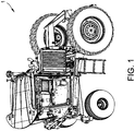
- Figure 1 shows an embodiment of a self-propelled vehicle 1.
- the vehicle includes a baling device 5 for forming a bale of crop or forage material.
- the self-propelled vehicle 1 may be an agricultural vehicle such as a mower and mower conditioner, merger, baler, rake, tedder, bale processor, bale mover, sprayer, broadcast spreader, fruit or nut harvester, or the like.
- the vehicle 1 is configured for non-agricultural use (e.g., construction, shipping or the like).
- baling device 5 should not be considered limiting and any suitable device may be substituted for the baling system unless stated differently (e.g., cutting or mower head, sickle bar, spray tank and/or booms, harvesting devices (e.g., grape or nut harvesting devices), broadcast spreader or the like).
- the vehicle 1 is adapted to carry a load (e.g., bale, herbicide, fertilizer, or harvested crop such as nuts or fruits).
- the device 5 (e.g., baling device 5) is supported by a chassis 9.
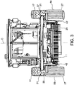
- the vehicle also includes a pick-up device 11 ( Fig. 3 ) that rotates to feed crop or forage material to the baling device 5.
- the vehicle 1 is controlled from an operator station 13 and is powered by an engine 101.
- engine 101 and device 5 are supported by the chassis 9 (i.e., the engine 101 is not part of a towed vehicle such as a tractor that releasably connects to the device by a hitch assembly attached to an implement tongue).
- the vehicle 1 includes first and second caster wheels 27 and first and second drive wheels 17.
- the term "caster wheel” includes a wheel mounted to a frame or chassis at a generally vertically oriented caster pivot so that the caster wheel is able to swivel about the caster pivot.
- Each of the wheels 17, 27 is connected to the chassis 9 and can be rotated around a rotational axis R 17 , R 27 .
- the drive wheels 17 have a common rotational axis R 17 and the caster wheels 27 have a common rotational axis R 27 .
- the drive wheels 17 are offset from each other and have different axes of rotation and/or the caster wheels 27 are offset from each other and have different axes of rotation.
- the vehicle 1 includes four wheels, though in other embodiments, the vehicle may include any number of drive and caster wheels.
- the speed and direction of travel may be controlled by a separate operator control.
- the vehicle 1 In the drive wheel steering mode, the vehicle 1 may be turned within its own footprint. In this mode, the caster wheels 27 self-align with the direction in which the drive wheels propel the vehicle, i.e., the caster wheels 27 follow the direction of travel of the rear drive wheels 17.
- the subframe 41 may have a single leg or may include any other arrangement of components that allows the caster wheels 27 to be positioned below the chassis 9 to support the vehicle.
- the caster wheels 27 are engaged by the steering system and used for steering.
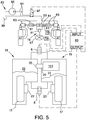
- the differential valves 8 ( Fig. 5 ) are opened (e.g., by energizing solenoids) with equal output from the drive wheel pumps 20 with the differential speeds of the drive wheels 17 being enabled by fluid flow through the differential valves 8.
- the differential valves 8 are opened and the output from the drive wheel pumps 20 is varied to the two drive wheels 17 based on the output of the control unit.
- the swivel position of the caster wheels 27 is controlled and the relative speeds of the drive wheels 17 is also controlled (e.g., similar to the drive wheel steering mode).
- the steering system 19 selectively engages a steering linkage to control the swivel position of the caster wheels 27 in the caster wheel steering mode.
- the steering system 19 may include a mechanical and/or electrical coupling mechanism to selectively engage the steering system with the caster wheels 27.
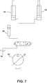
- the steering system 19 includes an orbital valve 51, a steering actuator 53 (shown as a hydraulic cylinder) and first and second tie rods 61 with each tie rod being connected to an opposite side of the steering actuator 53.
- the orbital valve 51 regulates fluid flow to the steering actuator 53 based on input from a steering device such as a steering wheel 67.
- the steering system 19 may include a steering pump (not shown) to provide the fluid flow.
- the steering device 67 is an operator and may be any suitable operator control such as a steering wheel, wheel lever, digital inputs, joystick, dual sticks, and/or a headset.
- the steering actuator 53 is a double acting cylinder having a through rod 65 that extends from each side of the barrel which pushes/pulls the tie rods 61 to commonly align the caster wheels 27 during caster wheel steering.
- the steering cylinder 53 includes inlet and outlet ports 70. Fluid flows through the ports 70 in a first direction to cause the through rod 65 to move to cause both caster wheels 27 to be steered. Fluid is caused to flow in the opposite direction to actuate the through rod 65 in the opposite direction, and to cause the caster wheels 27 to be steered in the opposite direction.
- Each tie rod 61 connects to a linkage 56 connected to the caster assembly shafts 37.
- Each tie rod 61 includes a disengagement cylinder 63 (e.g., a three-way cylinder) to enable selective steering of the caster wheels 27.
- the disengagement cylinders 63 are locked in an extended position such that actuation of the steering actuator 53 causes pivoting movement of the caster wheels 27 (i.e., the tie rods 61 are a fixed length).
- the disengagement cylinders 63 are allowed to float (i.e., fluid is allowed to freely flow with little or no pressure), thereby disengaging the movement of the steering actuator 53 from the caster wheels 27 (i.e., the tie rods 61 are variable in length). As such, actuation of the steering actuator 53 will not be translated through the disengagement cylinders 63 to the caster wheels 27 and the castor assemblies 31 will be allowed to freely pivot in the drive wheel steering mode.
- the disengagement cylinders 63 are connected to a hydraulic system 83 ( Fig. 5 ) that regulates the fluid flow to the cylinders 63.
- the hydraulic system 83 includes a pump 85, a valve 87, a hydraulic fluid tank 89, and fluid lines 91.
- the valve 87 allows oil into the cylinders to lock-out the disengagement cylinders 63 with pressure created by pump 85.
- valve 87 is shifted to allow fluid to freely flow in and out of the disengagement cylinders 63 and back to the tank 89.
- the steered caster wheel system includes mechanical connections from the steering device 67 to the caster wheels 27 for steering of the caster wheels 27 (i.e., includes only mechanical linkages and/or hydraulic components to translate movement of the steering device into caster wheel steering). In this mode, pivoting of the caster wheels 27 is not a response to a control unit signal.
- the vehicle 1 may include any steering system 19 that enables the vehicle to operate as described.
- the steering system 19 may include any of the following components, without limitation: tie rods, rack and pinion mechanisms, orbital valves, cylinders, motors, and bell cranks.
- the castor assemblies 31 are locked by manual and/or automatic mechanisms that prevent the castor assemblies from freely pivoting such as during the drive wheel steering mode.
- the vehicle 1 includes a control system to control the drive wheels 17 and front caster wheels 27 based on inputs from an operator.
- the control system includes a control unit 80, speed and direction control device 78, a mode selector 79 and steering device which is shown as a steering wheel 67.
- the speed and direction control device 78, mode selector 79 and steering wheel 67 may be controlled from the operator station 13.
- the control unit 80 includes a processor and a memory.
- the processor processes the signals received from various sensors, selectors and control devices of the system.
- the memory stores instructions that are executed by the processor.
- Control unit 80 may be a computer system.
- Computer systems as described herein, refer to any known computing device and computer system. As described herein, all such computer systems include a processor and a memory. However, any processor in a computer system referred to herein may also refer to one or more processors wherein the processor may be in one computing device or a plurality of computing devices acting in parallel. Additionally, any memory in a computer device referred to herein may also refer to one or more memories wherein the memories may be in one computing device or a plurality of computing devices acting in parallel.
- processor refers to central processing units, microprocessors, microcontrollers, reduced instruction set circuits (RISC), application specific integrated circuits (ASIC), logic circuits, and any other circuit or processor capable of executing the functions described herein.
- RISC reduced instruction set circuits
- ASIC application specific integrated circuits
- processor any other circuit or processor capable of executing the functions described herein.
- a computer program is provided to enable control unit 80, and this program is embodied on a computer readable medium.
- the computer system is executed on a single computer system, without requiring a connection to a server computer.
- the computer system is run in a Windows® environment (Windows is a registered trademark of Microsoft Corporation, Redmond, Washington).
- the computer system is run on a mainframe environment and a UNIX® server environment (UNIX is a registered trademark of X/Open Company Limited located in Reading, Berkshire, United Kingdom).
- the computer system is run in any suitable operating system environment.
- the computer program is flexible and designed to run in various different environments without compromising any major functionality.
- the computer system includes multiple components distributed among a plurality of computing devices. One or more components may be in the form of computer-executable instructions embodied in a computer-readable medium.
- the speed and direction control device 78 is typically hand-operated and may be a sliding lever that that causes an increase in forward speed as the lever is slid forward of a neutral position and an increase in reverse direction as the lever is slid rearward of the neutral position.
- the speed and direction control device 78 produces a signal in response to its position and the signal is transmitted to the control unit 80.
- the control unit 80 produces an output signal transmitted to the hydraulic pumps 20 that drive the rear wheels 17.
- the speed may also be controlled by a throttle that controls the engine speed.
- the vehicle 1 may be stopped by moving the speed and direction control device 78 to a zero-speed setting and/or by operating foot brake levers.
- steering may be performed by a steering device shown as a steering wheel 67 which regulates the steering system.
- a steering position sensor 81 measures the position of the steering actuator 53 and sends signals to the control unit 80 which generates an output (e.g., by an algorithm or look-up table) to control the difference in the rotation speed of the drive wheels 17.
- the sensor 81 is operatively connected to the control unit 80 to send the signals generated by the sensor to the control unit 80.
- the control unit 80 produces a signal based at least in part on the position of the actuator 53 that is transmitted to the hydraulic pumps 20 to independently regulate the rotational speeds of the first and second drive wheels 17 (i.e., the rotation speed and direction of rotation of each drive wheel 17).
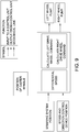
- the drive wheel steering mode is shown in Figure 9 .
- the orientation of the caster wheels is not controlled by a mechanical steering link or by output from the controller.
- the orientation of the caster wheels is independent from the steering system position and the position of the directional control device.
- the caster wheels follow the direction of travel of the vehicle as steered through rotation of the first and second drive wheels.
- the steering system position In the drive wheel steering mode, the steering system position, as measured by steering position sensor 81, sends a signal to a control unit.
- the "steering system position" of Figure 9 refers to the position of the steering actuator 53 and/or various linkages that position the caster wheels 27 (e.g., linkages that move even when caster wheel steering is disengaged as in the drive wheel steering mode).
- the steering system position is measured by the steering position sensor 81 and not by a sensor that measures the position on the steering device 67.
- the steering actuator 53 does not control the position of the caster wheels in the drive wheel steering mode.
- the steering position sensor 81 sends a signal to a control unit.
- a signal related to the position of the speed and direction control device is also sent to the control unit.
- the steering position signal and the speed and direction control device position signal are used to calculate a speed differential (e.g., through an algorithm or look-up table) that generates a turning radius of the self-propelled vehicle.
- a left drive wheel command and right drive wheel command are generated and transmitted to the left drive wheel pump and the right drive wheel pump.
- the commands control the output from the pumps (e.g., hydraulic output and direction of flow).
- the self-propelled vehicle may be operated by rotating the drive wheels at different speeds to steer the apparatus over an arc or in more aggressive manners in which one wheel remains stationary while the other wheel is rotated, or a zero-turn-radius mode where the drive wheels are rotated in opposite directions.
- zero-turning may be disabled when the self-propelled baler travels above a predetermined speed.
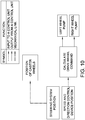
- the self-propelled vehicle 1 may also be selectively operated in a caster wheel steering or transport mode, as shown in Figure 10 .
- the steering device 67 sets/controls the steering actuator 53.
- the steering system position i.e., the position of the steering actuator 53
- the position of the steering system e.g., as measured by sensor 81
- the control unit is not used by the control unit.
- the steering system In the caster wheel steering mode, the steering system mechanically controls the orientation of the caster wheels such as by the steering system of Figure 6 .
- the speed and direction control device position signal is transmitted to a control unit to calculate a drive wheel command, with the left and right drive systems being controlled equally.
- the drive wheels In the transport mode of Figure 10 , the drive wheels are used to control the vehicle speed and not to steer the vehicle.
- the differential valve 8 of the differential system is opened to allow hydraulic flow to be transferred between the drive systems of the left and right rear wheels (e.g., upon cornering and the like) to improve maneuverability of the vehicles.
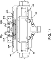
- the self-propelled vehicle 1 may be operated in a hybrid mode.
- the steering system mechanically controls the position of the caster wheels with the differential valves opened.
- the drive wheels are also controlled for steering based on the steering system positon as measured by steering position sensor 81 ( Fig. 14 ).
- the control unit determines the speed at which the drive wheels should vary in order to provide the curve that is consistent with the swivel position of the caster wheels.
- the self-propelled vehicle 1 is configured for autonomous operation.
- the vehicle may include sensors (e.g., cameras, GPS sensors and the like) that sense the position of a windrow and/or that may sense the position of the vehicle in the field.
- the vehicle 1 may also include a control unit that autonomously sends signals to control the vehicle speed and steering systems.
- the field in which the vehicle is propelled is mapped and the field map is used to autonomously control the operation of the vehicle in the field.
- the vehicle may include a riding station to carry an operator or the operator station may be eliminated.
- the vehicle also includes a baling device 5 that includes belts, rollers, belt tighteners, and a motor that drives the rollers.
- the baler forms bales in an expandable baling chamber, though, in other embodiments, the baler may be a fixed chamber baler.
- the baling chamber multiple belts are routed around the rollers and moved as a bale is formed, though a single bale forming belt may alternatively be used. Tension is maintained in the bale forming belts by the one or more belt tighteners to ensure a properly compressed bale.
- the baler includes a pick-up device 11 ( Fig. 3 ) to pick up crop or forage material.
- the pick-up device 11 is shown in a raised position.
- the pick-up device 11 is in a lowered position in which the rotating teeth of the device contact the crop or forage material and direct it toward the baling chamber.
- the pick-up device is powered by a motor.
- the baler moves across a field and along a windrow.
- the windrow may be formed by a mechanism, such as rakes, connected to the baler. Alternatively, the windrow may have been previously formed.
- the pick-up device collects material from the field and delivers the material to the baling chamber.
- the bale forming system forms the material into a bale within the baling chamber.
- a wrapping sequence is commenced by the wrapping mechanism 82.
- a tailgate 74 is opened and the full bale is discharged from the baling chamber and guided away from the baler by a ramp. Further details relating to the baling operation within the baling chamber can be found in U.S. Patent No. 7,181,900 , which is incorporated herein by reference.
- the engine 101 (e.g., gas or diesel powered engine) drives one or more hydraulic pumps which in turn power the various hydraulic motors and cylinders (e.g., first and second drive wheel motors, baling chamber motor, pick-up device motor, pick-up device lift cylinder, lift-gate cylinder and/or ramp cylinder).
- the engine 101 also provides power for the electrical systems of the vehicle.
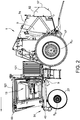
- the engine 101 is between the rotational axes R 17 of the rear drive wheels 17 and the rotational axes R 27 of the caster wheels 27. More specifically, the engine 101 is between the device 5 and the operator station 13.
- the "operator station” comprises the seat and controls for steering and controlling the speed of the vehicle.
- the operator station 13 is enclosed in a cab 121.
- the operator station 13 is forward of the device 5, forward of the rotational axis R 17 of the rear drive wheels 17 and is also forward to the engine 101.
- the cab 121 and operator station 13 may be partially aligned with the rotational axis R 27 of the caster wheels 27 (the steering wheel may be aligned with the rotational axis R 27 while the other controls and operator seat are rearward to the rotational axis).
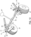
- FIG 12 shows a schematic of a portion of a steering system of other embodiments of the self-propelled baling vehicle.
- the self-propelled baling vehicle is similar to the vehicle shown in Figure 2 except the vehicle includes a different actuator 53 (rack and pinion) between the castor assembly 31 and the steering device 67.
- a tie rod 61 extends between each castor assembly 31 and the steering device 67.
- Each castor assembly 31 is rotatably connected to an end of a tie rod 61. In an unlocked mode, the castor assembly 31 freely pivots in relation to the tie rod 61. In a locked mode, the castor assembly 31 moves with and is pivoted by the tie rod 61.
- the steering measurement may be more reliable as the measurement is not affected by steering wheel creep (i.e., rotation of the steering wheel that does not cause a change in vehicle steering due to a loss of hydraulic fluid which causes an inconsistent relationship between the position of the steering device and the steering actuator).
- steering wheel creep i.e., rotation of the steering wheel that does not cause a change in vehicle steering due to a loss of hydraulic fluid which causes an inconsistent relationship between the position of the steering device and the steering actuator.
- a signal in both drive wheel steering mode and caster wheel steering mode may be produced.
- the caster wheels may be steered mechanically rather than by drive-by-wire in the caster wheel steering mode.
- the vehicle is versatile and has an increased operating efficiency.
Landscapes
- Engineering & Computer Science (AREA)
- Chemical & Material Sciences (AREA)
- Combustion & Propulsion (AREA)
- Mechanical Engineering (AREA)
- Transportation (AREA)
- Automation & Control Theory (AREA)
- Life Sciences & Earth Sciences (AREA)
- Environmental Sciences (AREA)
- Soil Sciences (AREA)
- Vehicle Body Suspensions (AREA)
- Aviation & Aerospace Engineering (AREA)
- Radar, Positioning & Navigation (AREA)
- Remote Sensing (AREA)
- Physics & Mathematics (AREA)
- General Physics & Mathematics (AREA)
- Steering-Linkage Mechanisms And Four-Wheel Steering (AREA)
- Guiding Agricultural Machines (AREA)
- Non-Deflectable Wheels, Steering Of Trailers, Or Other Steering (AREA)
Claims (15)
- Selbstangetriebenes Fahrzeug, mit:einem Fahrwerk (9);einem ersten und einem zweiten Antriebsrad (17), die mit dem Fahrwerk verbunden sind;einem ersten und einem zweiten Antriebssystem (15), die mit dem ersten und dem zweiten Antriebsrad derart verbunden sind, dass sie eine Drehantriebsgeschwindigkeit jeweils des ersten und des zweiten Antriebsrads unabhängig steuern;einem Lenksystem (19) zum Lenken des Fahrzeugs, mit:einer Lenkeinrichtung (67), wobei die Lenkreinrichtung ein Bedienersteuerelement ist;einem Lenkaktuator (53), der mit dem Bedienersteuerelement verbunden ist;gekennzeichnet durch:einen Lenkpositionssensor (81), der auf der Grundlage der Lage des Lenkaktuators ein Signal erzeugt; undeine Steuereinheit (80), die die Drehantriebsgeschwindigkeit des ersten Antriebsrads und die Drehantriebsgeschwindigkeit des zweiten Antriebsrads auf der Grundlage mindestens eines Teils des von dem Lenkpositionssensor erzeugten Signals einstellt, wobei eine Differenz der Drehantriebsgeschwindigkeit zwischen dem ersten und dem zweiten Antriebsrad das Fahrzeug lenkt.
- Selbstangetriebenes Fahrzeug nach Anspruch 1, wobei der Lenkaktuator ausgewählt ist aus einem Hydraulikzylinder, einem Zahnstangen- und Zahnradmechanismus und einem Lenkgetriebe mit Lenkhebel.
- Selbstangetriebenes Fahrzeug nach Anspruch 1 oder Anspruch 2, wobei die Lenkeinrichtung mit dem Lenkaktuator vorzugsweise durch ein Ringventil (51) verbunden ist, das mit der Lenkeinrichtung und hydraulisch mit dem Lenkaktuator verbunden ist.
- Selbstangetriebenes Fahrzeug nach einem der Ansprüche 1 bis 3, wobei die Lenkeinrichtung ein Lenkrad ist.
- Selbstangetriebenes Fahrzeug nach einem der Ansprüche 1 bis 4, das ferner aufweist:
eine erste und eine zweite Lenkrolle (27), die mit dem Fahrwerk verbunden sind, wobei der Lenkaktuator mit der ersten und der zweiten Lenkrolle verbunden ist, wobei das Lenksystem wahlweise betreibbar ist in einem Antriebsradlenkmodus und einem Lenkrollenlenkmodus, wobei das Lenksystem zum Lenken des Fahrzeugs in dem Lenkrollenlenkmodus eine Schwenkposition der Lenkrollen steuert, und wobei das Lenksystem zum Lenken des Fahrzeugs in dem Antriebsradlenkmodus den Geschwindigkeitsunterschied zwischen dem ersten und dem zweiten Antriebsrad steuert. - Selbstangetriebenes Fahrzeug nach Anspruch 5, wobei in dem Antriebsradlenkmodus die Lenkrollen in Bezug auf das Fahrwerk in Reaktion auf Unterschiede der Geschwindigkeit des ersten Antriebsrads und des zweiten Antriebsrads frei schwenkbar sind.
- Selbstangetriebenes Fahrzeug nach Anspruch 5 oder Anspruch 6, wobei in dem Lenkrollenlenkmodus die Lenkrollen mit dem Lenksystem verbunden und durch das Lenksystem gesteuert sind.
- Selbstangetriebenes Fahrzeug nach einem der Ansprüche 5 bis 7, wobei das Lenksystem eine erste Spurstange (61), die mit dem Lenkaktuator und der ersten Lenkrolle verbunden ist, und eine zweite Spurstange (61) aufweist, die mit dem Lenkaktuator und der zweiten Lenkrolle verbunden ist, wobei jede Spurstange einen Entkopplungszylinder aufweist, und wobei der Entkopplungszylinder (63) im Lenkrollenlenkmodus in einer festen Lage ist und in dem Antriebsradlenkmodus frei beweglich ist.
- Selbstangetriebenes Fahrzeug nach einem der Ansprüche 1 bis 8, wobei das erste Antriebssystem einen ersten Motor (23), der mit dem ersten Antriebsrad derart verbunden ist, dass er das erste Antriebsrad und eine erste Pumpe in Drehung versetzt, die mit dem ersten Motor verbunden ist, um dem ersten Motor Fluid zuzuführen, und wobei das zweite Antriebssystem einen zweiten Motor (23) aufweist, der mit dem zweiten Antriebsrad derart verbunden ist, dass er das zweite Antriebsrad und eine zweite Pumpe in Drehung versetzt, die mit dem zweiten Motor verbunden ist, um dem zweiten Motor Fluid zuzuführen, wobei die erste Pumpe eine erste Fluidströmung zu dem ersten Motor und die zweite Pumpe eine zweite Fluidströmung zu dem zweiten Motor hervorruft, und wobei die Steuereinheit die Geschwindigkeitsdifferenz zwischen dem ersten und dem zweiten Antriebsrad einstellt, indem in dem Antriebsradlenkmodus die erste und die zweite Fluidströmung variiert werden.
- Selbstangetriebenes Fahrzeug nach einem der Ansprüche 1 bis 9, das ferner eine landwirtschaftliche Einrichtung, die von dem Fahrwerk gehalten wird, aufweist, wobei die landwirtschaftliche Einrichtung ausgewählt ist aus: einer Ballenpresse, einem Rechen, einem Mäher, einer Mähaufbereitungseinheit, einem Heuwender, einer Sprüheinrichtung, einer Krautbearbeitungseinrichtung, einer Ballenverarbeitungseinrichtung, einer Ballentransporteinheit, einer Früchte- oder Nussernteeinrichtung, und einer Besprenkelungseinheit.
- Selbstangetriebenes Fahrzeug nach einem der Ansprüche 1 bis 10, wobei der Lenkaktuator ein Hydraulikzylinder mit einer Stange ist, die sich von einem Behälter aus erstreckt, wobei der Lenkpositionssensor die Lage der Stange misst.
- Selbstangetriebenes Fahrzeug nach einem der Ansprüche 1 bis 11, wobei der Lenkpositionssensor die Lage einer Spurstange, die sich von dem Aktuator aus erstreckt, misst.
- Selbstangetriebenes Fahrzeug nach einem der Ansprüche 1 bis 12, das ferner eine erste und eine zweite Lenkrolle, die mit dem Lenkaktuator verbunden sind, aufweist, wobei der Lenkpositionssensor die Winkellage mindestens einer der Lenkrollen misst.
- Selbstangetriebenes Fahrzeug nach einem der Ansprüche 1 bis 13, das ferner eine erste und eine zweite Lenkrolle aufweist, wobei die Lenkeinrichtung und der Lenkaktuator Bestandteile eines Lenkrollenlenksystems sind, wobei das Lenksystem nur mechanische Verbindungen zwischen der Lenkeinrichtung und den Lenkrollen aufweist.
- Selbstangetriebenes Fahrzeug nach einem der Ansprüche 1 bis 14, das ferner eine erste und eine zweite Lenkrolle aufweist, wobei die Lenkeinrichtung und der Lenkaktuator Bestandteile eines Lenkrollenlenksystems zur Steuerung der Schwenkposition der Lenkrollen sind, wobei eine Steuerung der Schwenkposition der Lenkrollen nicht eine Reaktion auf das Signal der Steuereinheit ist.
Applications Claiming Priority (1)
| Application Number | Priority Date | Filing Date | Title |
|---|---|---|---|
| US201762544132P | 2017-08-11 | 2017-08-11 |
Publications (3)
| Publication Number | Publication Date |
|---|---|
| EP3441287A2 EP3441287A2 (de) | 2019-02-13 |
| EP3441287A3 EP3441287A3 (de) | 2019-03-20 |
| EP3441287B1 true EP3441287B1 (de) | 2021-10-06 |
Family
ID=63174085
Family Applications (1)
| Application Number | Title | Priority Date | Filing Date |
|---|---|---|---|
| EP18187965.1A Active EP3441287B1 (de) | 2017-08-11 | 2018-08-08 | Selbstangetriebene fahrzeuge mit einem lenkpositionssensor |
Country Status (3)
| Country | Link |
|---|---|
| US (1) | US10850723B2 (de) |
| EP (1) | EP3441287B1 (de) |
| CA (1) | CA3013837C (de) |
Families Citing this family (8)
| Publication number | Priority date | Publication date | Assignee | Title |
|---|---|---|---|---|
| WO2017201452A1 (en) * | 2016-05-19 | 2017-11-23 | Vermeer Manufacturing Company | Self-propelled vehicles including a differential system |
| US11026368B2 (en) * | 2018-11-26 | 2021-06-08 | Cnh Industrial America Llc | Steering control system for harvester and methods of using the same |
| US11511642B2 (en) | 2019-04-05 | 2022-11-29 | Oshkosh Corporation | Electric concrete vehicle systems and methods |
| CN110606124B (zh) * | 2019-05-17 | 2020-08-07 | 合肥工业大学 | 方向盘位置校验方法及装置 |
| US10981024B1 (en) | 2019-10-11 | 2021-04-20 | Oshkosh Corporation | Hybrid fire fighting vehicle |
| JP7234962B2 (ja) * | 2020-02-11 | 2023-03-08 | トヨタ自動車株式会社 | 転舵装置およびそれが設けられたステアリングシステム |
| CN115703350A (zh) * | 2021-08-16 | 2023-02-17 | 余姚市爱优特电机有限公司 | 滚动式车辆 |
| CN119305626B (zh) * | 2024-11-29 | 2025-11-18 | 开沃新能源汽车集团股份有限公司 | 叉车转向轮的线控转向系统、方法及装置 |
Family Cites Families (28)
| Publication number | Priority date | Publication date | Assignee | Title |
|---|---|---|---|---|
| US3075233A (en) | 1960-07-20 | 1963-01-29 | Lorenz Clyde | Farm wagon caster wheel |
| US4090581A (en) * | 1976-11-04 | 1978-05-23 | Detroit Tool And Engineering Company | Carrier vehicle steering system |
| US4320810A (en) | 1979-12-17 | 1982-03-23 | Chromalloy American Corporation | Vehicle with improved steering system device |
| US4823899A (en) | 1986-07-10 | 1989-04-25 | Ashot Ashkelon Industries Ltd. | Steering apparatus |
| US4998596A (en) * | 1989-05-03 | 1991-03-12 | Ufi, Inc. | Self-propelled balancing three-wheeled vehicle |
| AUPM851294A0 (en) | 1994-09-29 | 1994-10-27 | O'Brien, Nelson Charles | Agricultural machine and implements therefor |
| WO2003026385A1 (en) | 2001-09-07 | 2003-04-03 | Dillon Ben N | Articulated combine |
| US7316288B1 (en) | 2003-01-27 | 2008-01-08 | Polaris Industries Inc. | All terrain vehicle with multiple steering modes |
| US6960973B2 (en) | 2003-06-18 | 2005-11-01 | The Cherry Corporation | Angular position sensor |
| US7624996B2 (en) * | 2003-11-14 | 2009-12-01 | Wright Manufacturing, Inc. | Walk-behind lawn mower sulky latch assembly |
| US7181900B2 (en) | 2003-11-21 | 2007-02-27 | Vermeer Manufacturing Co. | Netwrap feed and cut mechanism |
| US7478689B1 (en) * | 2006-03-21 | 2009-01-20 | Scag Power Equipment, Inc. | Vehicle steering and speed control |
| US7918305B2 (en) | 2007-02-05 | 2011-04-05 | The Toro Company | All-wheel steering system and vehicle incorporating the same |
| US8186697B2 (en) | 2008-01-03 | 2012-05-29 | Deere & Company | Suspension arrangement for rear castered wheels on a work machine |
| US7954573B2 (en) * | 2008-01-07 | 2011-06-07 | Jessen Thomas F | Drive-steering control system and vehicles equipped therewith |
| FR2943608B1 (fr) | 2009-03-31 | 2012-08-31 | Jean Marie Quenardel | Tracteur enjambeur a motricite electrique et a grande stabilite de trajectoire. |
| EP2435286A1 (de) * | 2009-05-29 | 2012-04-04 | El-Forest AB | Hybridnutzfahrzeug |
| US8893831B2 (en) | 2011-09-22 | 2014-11-25 | Macdon Industries Ltd. | Swather tractor with rear wheel active steering |
| US8733770B2 (en) * | 2011-12-19 | 2014-05-27 | Agco Corporation | Steerable rear axle system for dual-path steered windrower tractor |
| US8690171B2 (en) * | 2011-12-19 | 2014-04-08 | Agco Corporation | Individually steered rear axle for dual path steered vehicles |
| US9168784B2 (en) * | 2013-03-15 | 2015-10-27 | Cnh Industrial America Llc | Self-propelled windrower tailwheel non-zero caster for stability |
| CA2881892C (en) | 2014-02-11 | 2017-04-25 | Agco Corporation | Self-propelled agricultural machine with dual driving modes |
| DE102014104549A1 (de) | 2014-04-01 | 2015-10-01 | Claas Selbstfahrende Erntemaschinen Gmbh | Lenkbares Raupenfahrwerk |
| US9439341B2 (en) | 2014-08-08 | 2016-09-13 | Deere & Company | Multi-mode steering control for a vehicle |
| GB2539627A (en) * | 2015-04-22 | 2016-12-28 | I-Glider Ltd | A reconfigurable wheeled personal mobility device |
| US10087603B2 (en) * | 2016-09-28 | 2018-10-02 | Caterpillar Inc. | Stability control system for machine in motion |
| CA2956933A1 (en) * | 2017-02-03 | 2018-08-03 | Kelso Technologies Inc. | Active suspension control system and method for no-road vehicles |
| US10967695B2 (en) * | 2018-03-02 | 2021-04-06 | Blueline Mfg., Co. | Steerable suspension system |
-
2018
- 2018-08-07 US US16/056,712 patent/US10850723B2/en active Active
- 2018-08-08 EP EP18187965.1A patent/EP3441287B1/de active Active
- 2018-08-10 CA CA3013837A patent/CA3013837C/en active Active
Non-Patent Citations (1)
| Title |
|---|
| None * |
Also Published As
| Publication number | Publication date |
|---|---|
| CA3013837C (en) | 2020-08-25 |
| US10850723B2 (en) | 2020-12-01 |
| EP3441287A3 (de) | 2019-03-20 |
| US20190047541A1 (en) | 2019-02-14 |
| CA3013837A1 (en) | 2019-02-11 |
| EP3441287A2 (de) | 2019-02-13 |
Similar Documents
| Publication | Publication Date | Title |
|---|---|---|
| EP3441287B1 (de) | Selbstangetriebene fahrzeuge mit einem lenkpositionssensor | |
| EP3827653B1 (de) | Fahrzeug mit gelenkten nachlaufrädern | |
| EP3458334B1 (de) | Selbstangetriebene fahrzeuge mit einem differenzialsystem | |
| US11800826B2 (en) | Self-propelled baling vehicle | |
| EP3441244B1 (de) | Selbstfahrende fahrzeuge mit nicksteuerung | |
| US8733770B2 (en) | Steerable rear axle system for dual-path steered windrower tractor | |
| CA2651756C (en) | Articulated transport arrangement for windrower with cutting platform | |
| WO2017201445A1 (en) | Self-propelled vehicles | |
| WO2017201396A1 (en) | A modular self-propelled vehicle for supporting and operating a device | |
| GB2562378A (en) | Self-propelled windrower with towing mode for use with a pull-type mower conditioner |
Legal Events
| Date | Code | Title | Description |
|---|---|---|---|
| PUAI | Public reference made under article 153(3) epc to a published international application that has entered the european phase |
Free format text: ORIGINAL CODE: 0009012 |
|
| STAA | Information on the status of an ep patent application or granted ep patent |
Free format text: STATUS: REQUEST FOR EXAMINATION WAS MADE |
|
| 17P | Request for examination filed |
Effective date: 20180830 |
|
| AK | Designated contracting states |
Kind code of ref document: A2 Designated state(s): AL AT BE BG CH CY CZ DE DK EE ES FI FR GB GR HR HU IE IS IT LI LT LU LV MC MK MT NL NO PL PT RO RS SE SI SK SM TR |
|
| AX | Request for extension of the european patent |
Extension state: BA ME |
|
| PUAL | Search report despatched |
Free format text: ORIGINAL CODE: 0009013 |
|
| AK | Designated contracting states |
Kind code of ref document: A3 Designated state(s): AL AT BE BG CH CY CZ DE DK EE ES FI FR GB GR HR HU IE IS IT LI LT LU LV MC MK MT NL NO PL PT RO RS SE SI SK SM TR |
|
| AX | Request for extension of the european patent |
Extension state: BA ME |
|
| RIC1 | Information provided on ipc code assigned before grant |
Ipc: B62D 11/00 20060101AFI20190208BHEP Ipc: B62D 11/24 20060101ALI20190208BHEP Ipc: B62D 15/02 20060101ALI20190208BHEP |
|
| STAA | Information on the status of an ep patent application or granted ep patent |
Free format text: STATUS: EXAMINATION IS IN PROGRESS |
|
| 17Q | First examination report despatched |
Effective date: 20200922 |
|
| GRAP | Despatch of communication of intention to grant a patent |
Free format text: ORIGINAL CODE: EPIDOSNIGR1 |
|
| STAA | Information on the status of an ep patent application or granted ep patent |
Free format text: STATUS: GRANT OF PATENT IS INTENDED |
|
| INTG | Intention to grant announced |
Effective date: 20210413 |
|
| GRAS | Grant fee paid |
Free format text: ORIGINAL CODE: EPIDOSNIGR3 |
|
| GRAA | (expected) grant |
Free format text: ORIGINAL CODE: 0009210 |
|
| STAA | Information on the status of an ep patent application or granted ep patent |
Free format text: STATUS: THE PATENT HAS BEEN GRANTED |
|
| AK | Designated contracting states |
Kind code of ref document: B1 Designated state(s): AL AT BE BG CH CY CZ DE DK EE ES FI FR GB GR HR HU IE IS IT LI LT LU LV MC MK MT NL NO PL PT RO RS SE SI SK SM TR |
|
| REG | Reference to a national code |
Ref country code: GB Ref legal event code: FG4D |
|
| REG | Reference to a national code |
Ref country code: CH Ref legal event code: EP Ref country code: AT Ref legal event code: REF Ref document number: 1435987 Country of ref document: AT Kind code of ref document: T Effective date: 20211015 |
|
| REG | Reference to a national code |
Ref country code: IE Ref legal event code: FG4D |
|
| REG | Reference to a national code |
Ref country code: DE Ref legal event code: R096 Ref document number: 602018024522 Country of ref document: DE |
|
| REG | Reference to a national code |
Ref country code: LT Ref legal event code: MG9D |
|
| REG | Reference to a national code |
Ref country code: NL Ref legal event code: MP Effective date: 20211006 |
|
| REG | Reference to a national code |
Ref country code: AT Ref legal event code: MK05 Ref document number: 1435987 Country of ref document: AT Kind code of ref document: T Effective date: 20211006 |
|
| PG25 | Lapsed in a contracting state [announced via postgrant information from national office to epo] |
Ref country code: RS Free format text: LAPSE BECAUSE OF FAILURE TO SUBMIT A TRANSLATION OF THE DESCRIPTION OR TO PAY THE FEE WITHIN THE PRESCRIBED TIME-LIMIT Effective date: 20211006 Ref country code: LT Free format text: LAPSE BECAUSE OF FAILURE TO SUBMIT A TRANSLATION OF THE DESCRIPTION OR TO PAY THE FEE WITHIN THE PRESCRIBED TIME-LIMIT Effective date: 20211006 Ref country code: FI Free format text: LAPSE BECAUSE OF FAILURE TO SUBMIT A TRANSLATION OF THE DESCRIPTION OR TO PAY THE FEE WITHIN THE PRESCRIBED TIME-LIMIT Effective date: 20211006 Ref country code: BG Free format text: LAPSE BECAUSE OF FAILURE TO SUBMIT A TRANSLATION OF THE DESCRIPTION OR TO PAY THE FEE WITHIN THE PRESCRIBED TIME-LIMIT Effective date: 20220106 Ref country code: AT Free format text: LAPSE BECAUSE OF FAILURE TO SUBMIT A TRANSLATION OF THE DESCRIPTION OR TO PAY THE FEE WITHIN THE PRESCRIBED TIME-LIMIT Effective date: 20211006 |
|
| PG25 | Lapsed in a contracting state [announced via postgrant information from national office to epo] |
Ref country code: IS Free format text: LAPSE BECAUSE OF FAILURE TO SUBMIT A TRANSLATION OF THE DESCRIPTION OR TO PAY THE FEE WITHIN THE PRESCRIBED TIME-LIMIT Effective date: 20220206 Ref country code: SE Free format text: LAPSE BECAUSE OF FAILURE TO SUBMIT A TRANSLATION OF THE DESCRIPTION OR TO PAY THE FEE WITHIN THE PRESCRIBED TIME-LIMIT Effective date: 20211006 Ref country code: PT Free format text: LAPSE BECAUSE OF FAILURE TO SUBMIT A TRANSLATION OF THE DESCRIPTION OR TO PAY THE FEE WITHIN THE PRESCRIBED TIME-LIMIT Effective date: 20220207 Ref country code: PL Free format text: LAPSE BECAUSE OF FAILURE TO SUBMIT A TRANSLATION OF THE DESCRIPTION OR TO PAY THE FEE WITHIN THE PRESCRIBED TIME-LIMIT Effective date: 20211006 Ref country code: NO Free format text: LAPSE BECAUSE OF FAILURE TO SUBMIT A TRANSLATION OF THE DESCRIPTION OR TO PAY THE FEE WITHIN THE PRESCRIBED TIME-LIMIT Effective date: 20220106 Ref country code: NL Free format text: LAPSE BECAUSE OF FAILURE TO SUBMIT A TRANSLATION OF THE DESCRIPTION OR TO PAY THE FEE WITHIN THE PRESCRIBED TIME-LIMIT Effective date: 20211006 Ref country code: LV Free format text: LAPSE BECAUSE OF FAILURE TO SUBMIT A TRANSLATION OF THE DESCRIPTION OR TO PAY THE FEE WITHIN THE PRESCRIBED TIME-LIMIT Effective date: 20211006 Ref country code: HR Free format text: LAPSE BECAUSE OF FAILURE TO SUBMIT A TRANSLATION OF THE DESCRIPTION OR TO PAY THE FEE WITHIN THE PRESCRIBED TIME-LIMIT Effective date: 20211006 Ref country code: GR Free format text: LAPSE BECAUSE OF FAILURE TO SUBMIT A TRANSLATION OF THE DESCRIPTION OR TO PAY THE FEE WITHIN THE PRESCRIBED TIME-LIMIT Effective date: 20220107 Ref country code: ES Free format text: LAPSE BECAUSE OF FAILURE TO SUBMIT A TRANSLATION OF THE DESCRIPTION OR TO PAY THE FEE WITHIN THE PRESCRIBED TIME-LIMIT Effective date: 20211006 |
|
| REG | Reference to a national code |
Ref country code: DE Ref legal event code: R097 Ref document number: 602018024522 Country of ref document: DE |
|
| PG25 | Lapsed in a contracting state [announced via postgrant information from national office to epo] |
Ref country code: SM Free format text: LAPSE BECAUSE OF FAILURE TO SUBMIT A TRANSLATION OF THE DESCRIPTION OR TO PAY THE FEE WITHIN THE PRESCRIBED TIME-LIMIT Effective date: 20211006 Ref country code: SK Free format text: LAPSE BECAUSE OF FAILURE TO SUBMIT A TRANSLATION OF THE DESCRIPTION OR TO PAY THE FEE WITHIN THE PRESCRIBED TIME-LIMIT Effective date: 20211006 Ref country code: RO Free format text: LAPSE BECAUSE OF FAILURE TO SUBMIT A TRANSLATION OF THE DESCRIPTION OR TO PAY THE FEE WITHIN THE PRESCRIBED TIME-LIMIT Effective date: 20211006 Ref country code: EE Free format text: LAPSE BECAUSE OF FAILURE TO SUBMIT A TRANSLATION OF THE DESCRIPTION OR TO PAY THE FEE WITHIN THE PRESCRIBED TIME-LIMIT Effective date: 20211006 Ref country code: DK Free format text: LAPSE BECAUSE OF FAILURE TO SUBMIT A TRANSLATION OF THE DESCRIPTION OR TO PAY THE FEE WITHIN THE PRESCRIBED TIME-LIMIT Effective date: 20211006 Ref country code: CZ Free format text: LAPSE BECAUSE OF FAILURE TO SUBMIT A TRANSLATION OF THE DESCRIPTION OR TO PAY THE FEE WITHIN THE PRESCRIBED TIME-LIMIT Effective date: 20211006 |
|
| PLBE | No opposition filed within time limit |
Free format text: ORIGINAL CODE: 0009261 |
|
| STAA | Information on the status of an ep patent application or granted ep patent |
Free format text: STATUS: NO OPPOSITION FILED WITHIN TIME LIMIT |
|
| 26N | No opposition filed |
Effective date: 20220707 |
|
| PG25 | Lapsed in a contracting state [announced via postgrant information from national office to epo] |
Ref country code: AL Free format text: LAPSE BECAUSE OF FAILURE TO SUBMIT A TRANSLATION OF THE DESCRIPTION OR TO PAY THE FEE WITHIN THE PRESCRIBED TIME-LIMIT Effective date: 20211006 |
|
| PG25 | Lapsed in a contracting state [announced via postgrant information from national office to epo] |
Ref country code: SI Free format text: LAPSE BECAUSE OF FAILURE TO SUBMIT A TRANSLATION OF THE DESCRIPTION OR TO PAY THE FEE WITHIN THE PRESCRIBED TIME-LIMIT Effective date: 20211006 |
|
| PG25 | Lapsed in a contracting state [announced via postgrant information from national office to epo] |
Ref country code: MC Free format text: LAPSE BECAUSE OF FAILURE TO SUBMIT A TRANSLATION OF THE DESCRIPTION OR TO PAY THE FEE WITHIN THE PRESCRIBED TIME-LIMIT Effective date: 20211006 |
|
| REG | Reference to a national code |
Ref country code: CH Ref legal event code: PL |
|
| GBPC | Gb: european patent ceased through non-payment of renewal fee |
Effective date: 20220808 |
|
| PG25 | Lapsed in a contracting state [announced via postgrant information from national office to epo] |
Ref country code: LU Free format text: LAPSE BECAUSE OF NON-PAYMENT OF DUE FEES Effective date: 20220808 Ref country code: LI Free format text: LAPSE BECAUSE OF NON-PAYMENT OF DUE FEES Effective date: 20220831 Ref country code: CH Free format text: LAPSE BECAUSE OF NON-PAYMENT OF DUE FEES Effective date: 20220831 |
|
| REG | Reference to a national code |
Ref country code: BE Ref legal event code: MM Effective date: 20220831 |
|
| PG25 | Lapsed in a contracting state [announced via postgrant information from national office to epo] |
Ref country code: IT Free format text: LAPSE BECAUSE OF FAILURE TO SUBMIT A TRANSLATION OF THE DESCRIPTION OR TO PAY THE FEE WITHIN THE PRESCRIBED TIME-LIMIT Effective date: 20211006 |
|
| P01 | Opt-out of the competence of the unified patent court (upc) registered |
Effective date: 20230526 |
|
| PG25 | Lapsed in a contracting state [announced via postgrant information from national office to epo] |
Ref country code: BE Free format text: LAPSE BECAUSE OF NON-PAYMENT OF DUE FEES Effective date: 20220831 |
|
| PG25 | Lapsed in a contracting state [announced via postgrant information from national office to epo] |
Ref country code: GB Free format text: LAPSE BECAUSE OF NON-PAYMENT OF DUE FEES Effective date: 20220808 |
|
| PG25 | Lapsed in a contracting state [announced via postgrant information from national office to epo] |
Ref country code: HU Free format text: LAPSE BECAUSE OF FAILURE TO SUBMIT A TRANSLATION OF THE DESCRIPTION OR TO PAY THE FEE WITHIN THE PRESCRIBED TIME-LIMIT; INVALID AB INITIO Effective date: 20180808 |
|
| PG25 | Lapsed in a contracting state [announced via postgrant information from national office to epo] |
Ref country code: CY Free format text: LAPSE BECAUSE OF FAILURE TO SUBMIT A TRANSLATION OF THE DESCRIPTION OR TO PAY THE FEE WITHIN THE PRESCRIBED TIME-LIMIT Effective date: 20211006 |
|
| PG25 | Lapsed in a contracting state [announced via postgrant information from national office to epo] |
Ref country code: MK Free format text: LAPSE BECAUSE OF FAILURE TO SUBMIT A TRANSLATION OF THE DESCRIPTION OR TO PAY THE FEE WITHIN THE PRESCRIBED TIME-LIMIT Effective date: 20211006 |
|
| PG25 | Lapsed in a contracting state [announced via postgrant information from national office to epo] |
Ref country code: MT Free format text: LAPSE BECAUSE OF FAILURE TO SUBMIT A TRANSLATION OF THE DESCRIPTION OR TO PAY THE FEE WITHIN THE PRESCRIBED TIME-LIMIT Effective date: 20211006 |
|
| PGFP | Annual fee paid to national office [announced via postgrant information from national office to epo] |
Ref country code: DE Payment date: 20250709 Year of fee payment: 8 |
|
| PGFP | Annual fee paid to national office [announced via postgrant information from national office to epo] |
Ref country code: FR Payment date: 20250709 Year of fee payment: 8 |
|
| PGFP | Annual fee paid to national office [announced via postgrant information from national office to epo] |
Ref country code: IE Payment date: 20250709 Year of fee payment: 8 |
|
| PG25 | Lapsed in a contracting state [announced via postgrant information from national office to epo] |
Ref country code: TR Free format text: LAPSE BECAUSE OF FAILURE TO SUBMIT A TRANSLATION OF THE DESCRIPTION OR TO PAY THE FEE WITHIN THE PRESCRIBED TIME-LIMIT Effective date: 20211006 |