EP3441283A1 - Stroller frame - Google Patents
Stroller frame Download PDFInfo
- Publication number
- EP3441283A1 EP3441283A1 EP18157935.0A EP18157935A EP3441283A1 EP 3441283 A1 EP3441283 A1 EP 3441283A1 EP 18157935 A EP18157935 A EP 18157935A EP 3441283 A1 EP3441283 A1 EP 3441283A1
- Authority
- EP
- European Patent Office
- Prior art keywords
- disposed
- rod
- seat
- assemblies
- supporting
- Prior art date
- Legal status (The legal status is an assumption and is not a legal conclusion. Google has not performed a legal analysis and makes no representation as to the accuracy of the status listed.)
- Withdrawn
Links
Images


Classifications
-
- B—PERFORMING OPERATIONS; TRANSPORTING
- B62—LAND VEHICLES FOR TRAVELLING OTHERWISE THAN ON RAILS
- B62B—HAND-PROPELLED VEHICLES, e.g. HAND CARTS OR PERAMBULATORS; SLEDGES
- B62B7/00—Carriages for children; Perambulators, e.g. dolls' perambulators
- B62B7/04—Carriages for children; Perambulators, e.g. dolls' perambulators having more than one wheel axis; Steering devices therefor
- B62B7/06—Carriages for children; Perambulators, e.g. dolls' perambulators having more than one wheel axis; Steering devices therefor collapsible or foldable
- B62B7/08—Carriages for children; Perambulators, e.g. dolls' perambulators having more than one wheel axis; Steering devices therefor collapsible or foldable in the direction of, or at right angles to, the wheel axis
- B62B7/086—Carriages for children; Perambulators, e.g. dolls' perambulators having more than one wheel axis; Steering devices therefor collapsible or foldable in the direction of, or at right angles to, the wheel axis becoming smaller in all three dimensions
-
- B—PERFORMING OPERATIONS; TRANSPORTING
- B62—LAND VEHICLES FOR TRAVELLING OTHERWISE THAN ON RAILS
- B62B—HAND-PROPELLED VEHICLES, e.g. HAND CARTS OR PERAMBULATORS; SLEDGES
- B62B7/00—Carriages for children; Perambulators, e.g. dolls' perambulators
- B62B7/04—Carriages for children; Perambulators, e.g. dolls' perambulators having more than one wheel axis; Steering devices therefor
- B62B7/06—Carriages for children; Perambulators, e.g. dolls' perambulators having more than one wheel axis; Steering devices therefor collapsible or foldable
- B62B7/062—Coupling unit between front wheels, rear wheels and handle
-
- B—PERFORMING OPERATIONS; TRANSPORTING
- B62—LAND VEHICLES FOR TRAVELLING OTHERWISE THAN ON RAILS
- B62B—HAND-PROPELLED VEHICLES, e.g. HAND CARTS OR PERAMBULATORS; SLEDGES
- B62B9/00—Accessories or details specially adapted for children's carriages or perambulators
- B62B9/10—Perambulator bodies; Equipment therefor
- B62B9/12—Perambulator bodies; Equipment therefor involving parts that are adjustable, attachable or detachable
-
- B—PERFORMING OPERATIONS; TRANSPORTING
- B62—LAND VEHICLES FOR TRAVELLING OTHERWISE THAN ON RAILS
- B62B—HAND-PROPELLED VEHICLES, e.g. HAND CARTS OR PERAMBULATORS; SLEDGES
- B62B9/00—Accessories or details specially adapted for children's carriages or perambulators
- B62B9/20—Handle bars; Handles
-
- B—PERFORMING OPERATIONS; TRANSPORTING
- B62—LAND VEHICLES FOR TRAVELLING OTHERWISE THAN ON RAILS
- B62B—HAND-PROPELLED VEHICLES, e.g. HAND CARTS OR PERAMBULATORS; SLEDGES
- B62B2205/00—Hand-propelled vehicles or sledges being foldable or dismountable when not in use
- B62B2205/02—Hand-propelled vehicles or sledges being foldable or dismountable when not in use foldable widthwise
-
- B—PERFORMING OPERATIONS; TRANSPORTING
- B62—LAND VEHICLES FOR TRAVELLING OTHERWISE THAN ON RAILS
- B62B—HAND-PROPELLED VEHICLES, e.g. HAND CARTS OR PERAMBULATORS; SLEDGES
- B62B2205/00—Hand-propelled vehicles or sledges being foldable or dismountable when not in use
- B62B2205/12—Collapsible wheels
-
- B—PERFORMING OPERATIONS; TRANSPORTING
- B62—LAND VEHICLES FOR TRAVELLING OTHERWISE THAN ON RAILS
- B62B—HAND-PROPELLED VEHICLES, e.g. HAND CARTS OR PERAMBULATORS; SLEDGES
- B62B2205/00—Hand-propelled vehicles or sledges being foldable or dismountable when not in use
- B62B2205/20—Catches; Locking or releasing an articulation
- B62B2205/23—Catches; Locking or releasing an articulation foot operated
-
- B—PERFORMING OPERATIONS; TRANSPORTING
- B62—LAND VEHICLES FOR TRAVELLING OTHERWISE THAN ON RAILS
- B62B—HAND-PROPELLED VEHICLES, e.g. HAND CARTS OR PERAMBULATORS; SLEDGES
- B62B9/00—Accessories or details specially adapted for children's carriages or perambulators
- B62B9/08—Braking mechanisms; Locking devices against movement
- B62B9/082—Braking mechanisms; Locking devices against movement foot operated
Definitions
- the present invention relates to a stroller frame, and more particularly to a stroller frame that can be folded and expanded.
- a conventional stroller frame has a body having multiple foldable joints. Two front wheels are respectively disposed on two sides of a front end of a bottom of the body. Two rear wheels are respectively disposed on two sides of a rear end of a bottom of the body.
- the conventional stroller frame can be folded and expanded by the foldable joints of the body. When the conventional stroller frame is expanded, a baby or a toddler can be seated in the conventional stroller frame, and then the conventional stroller frame can be pushed to move. When the conventional stroller frame is folded, an occupied space of the conventional stroller frame could be decreased for ease in storage and carriage.
- a distance between the two rear wheels is larger than a distance between the two front wheels.
- the conventional stroller frame is folded by the foldable joints. After the conventional stroller frame is folded, the two rear wheels are located behind the two front wheels or are located at the outer sides of the two front wheels. Therefore, the overall width of the folded conventional stroller frame is still large. The overall volume of the folded conventional stroller frame is hard to decrease and occupies much space.
- a bearing mechanism for the baby/toddler to be seated is supported by two linkage assemblies at two sides of the conventional stroller frame respectively. Thus, a capacity of the bearing mechanism is inadequate with the two linkage assemblies.
- the present invention tends to provide a stroller frame to mitigate or obviate the aforementioned problems.
- the main objective of the invention is to provide a stroller frame that may solve the problems that the overall width of the conventional stroller frame when folded is still large, and the overall volume of the folded conventional stroller frame is hard to decrease and occupies much space.
- the stroller frame has a body, two front wheel assemblies, a seat supporting mechanism, and a rear wheel folding mechanism.
- the body has a front end having two sides, a rear side, a front wheel bracket, two first joint assemblies, a seat supporting bracket, a seat plate, two inclined rods, two second joint assemblies, a handle, a first transverse rod, a second transverse rod, and a linkage shaft.
- the front wheel bracket has a front, a rear, a top, and two top portions.
- the two top portions are disposed at a spaced interval and are inclined toward the top of the front wheel bracket from the front of the front wheel bracket to the rear of the front wheel bracket.
- the two first joint assemblies are respectively disposed on the two top portions of the front wheel bracket.
- the seat supporting bracket is disposed on the two first joint assemblies.
- the seat plate is disposed on the seat supporting bracket and has a middle section and a rear section.
- the two inclined rods are respectively disposed on the two first joint assemblies.
- the two second joint assemblies are respectively disposed on the two inclined rods.
- the handle is disposed across the two second joint assemblies and has two longitudinal portions and a transverse portion. The two longitudinal portions are respectively disposed on the two second joint assemblies.
- the transverse portion is disposed across the two longitudinal portions and has an operating assembly disposed on the transverse portion.
- the operating assembly controls the two first joint assemblies and the two second joint assemblies.
- the first transverse rod is disposed across the two first joint assemblies below the seat supporting bracket.
- the second transverse rod is disposed across the two top portions of the front wheel bracket below the seat supporting bracket, is parallel with the first transverse rod, is located ahead and below the first transverse rod, and has two ends.
- the linkage shaft is disposed below the rear section of the seat plate, and is linkingly connected between the two first joint assemblies.
- the two front wheel assemblies are respectively and pivotally disposed on the two sides of the front end of the body.
- Each front wheel assembly has a front wheel seat and a front wheel.
- the front wheel seat is pivotally disposed on the body.
- the front wheel is pivotally disposed on the front wheel seat.
- the seat supporting mechanism is moveably disposed below the seat plate of the body, and has a first arc-shaped plate, a second arc-shaped plate, and a supporting plate.
- a top end of the first arc-shaped plate is pivotally disposed on the middle section of the seat plate.
- a bottom end of the second arc-shaped plate is pivotally disposed on the second transverse rod.
- a top end of the supporting plate is connected to the linkage shaft.
- a bottom end of the first arc-shaped plate, a top end of the second arc-shaped plate, and a bottom end of the supporting plate are connected with each other by a pivot.
- the rear wheel folding mechanism is disposed on the rear side of the body and has two rear wheel assemblies and two linkage assemblies.
- the two rear wheel assemblies are moveably disposed on the first transverse rod of the body.
- Each rear wheel assembly has a rear wheel seat, a rear wheel, a connecting rod, and a connecting seat.
- the rear wheel seat has a top portion and a side.
- the rear wheel has a wheel shaft pivotally disposed on the side of the rear wheel seat.
- the wheel shaft has a central line defined along a longitudinal direction of the wheel shaft.
- the connecting rod is securely disposed on the top portion of the rear wheel seat and has a longitudinal direction, a central line defined along the longitudinal direction of the connecting rod, and a top end.
- An angle is defined between the central line of the connecting rod and the central line of the wheel shaft and is an acute angle.
- the connecting seat is pivotally disposed on the top end of the connecting rod, is obliquely and securely mounted on the first transverse rod, and has a pivoting portion, a fixing portion, and a stopping portion.
- the pivoting portion is pivotally disposed on the top end of the connecting rod by a pivoting pin and has a top end and a bottom end.
- the fixing portion is formed on the top end of the pivoting portion.
- the connecting seat is securely mounted on the first transverse rod by the fixing portion.
- the stopping portion is formed on the bottom end of the pivoting portion, and is located behind the top end of the connecting rod for limiting a backward rotating angle between the connecting rod and the connecting seat.
- the connecting seats of the two rear wheel assemblies are inclined outwardly from top to bottom of the body.
- the two connecting rods are symmetrical and are splayed from top to bottom of the body.
- a distance between the two rear wheels is larger than a distance between the two front wheels.
- the two rear wheels move between the two front wheels by the connecting seats inclined and the two connecting rods splayed.
- the two linkage assemblies are respectively disposed on the two ends of the second transverse rod, and are respectively located out of and connected to the connecting rods of the two rear wheel assemblies.
- Each linkage assembly has a first linkage rod, a second linkage rod, a first multi-directional connector, and a second multi-directional connector.
- An end of the first linkage rod is connected to the second transverse rod.
- the other end of the first linkage rod is combined to the first multi-directional connector to connect to an end of the second linkage rod.
- the other end of the second linkage rod is combined to the second multi-directional connector to connect to a middle section of a corresponding one of the connecting rods.
- the rear wheel folding mechanism is disposed on the rear side of the body.
- the two rear wheel assemblies are foldable and are obliquely and symmetrically disposed on the first transverse rod of the body.
- the two linkage assemblies are connected between the connecting rods of the two rear wheel assemblies and the second transverse rod of the body.
- the connecting seats are obliquely mounted and guide the connecting rods to splay from top to bottom of the body.
- the distance between the two rear wheels is larger than a distance between the two front wheels.
- the two linkage assemblies are expanded simultaneously to support the splayed connecting rods.
- the seat supporting mechanism is foldable, is located at the body, and is connected between a bottom of the seat plate, the first transverse rod, and the second transverse rod to form a foldable multi-point supporting mechanism to provide stable auxiliary strength to the seat plate.
- the rear wheel folding mechanism is spread steadily.
- the stroller frame can be pushed and moves steadily.
- the two linkage assemblies When the stroller frame is folded, the two linkage assemblies are folded and drive the connecting rods of the two rear wheel assemblies to respectively rotate along the pivoting pins of the pivoting portions of the connecting seats for moving toward the front wheel bracket.
- the first multi-directional connector is connected to the first linkage rod and the second linkage rod.
- the second multi-directional connector is connected to the second linkage rod and a corresponding one of the two connecting rods.
- the connecting rods are guided and move toward a middle direction of the rear wheel folding mechanism.
- the two rear wheels can move to and be disposed between the two front wheels.
- the overall width and volume of the folded stroller frame are decreased to overcome the problems that the two rear wheels of the conventional folded stroller frame are located at outer sides of the two front wheels of the conventional folded stroller frame, the overall width of the conventional stroller frame is still large when folded, and the overall volume of the folded conventional stroller frame is hard to decrease and occupies much space.
- the linkage shaft is driven by the first joint assemblies for driving the supporting plate to pull the seat supporting mechanism to fold automatically.
- a stroller frame in accordance with the present invention comprises a body 1, two front wheel assemblies 2, a seat supporting mechanism 3, and a rear wheel folding mechanism 4.
- the body 1 has a front end having two sides, a rear side, a front wheel bracket 10, two first joint assemblies 12A, a seat supporting bracket 11, a seat plate 111, two inclined rods 13, two second joint assemblies 12B, a handle 14, a first transverse rod 16, a second transverse rod 17, and a linkage shaft 121.
- the front wheel bracket 10 has a front, a rear, a top, and two top portions 101.
- the two top portions 101 are disposed at a spaced interval and are inclined toward the top of the front wheel bracket 10 from the front of the front wheel bracket 10 to the rear of the front wheel bracket 10.
- the two first joint assemblies 12A are respectively disposed on the two top portions 101 of the front wheel bracket 10.
- the seat supporting bracket 11 is disposed on the two first joint assemblies 12A.
- the seat plate 111 is disposed on the seat supporting bracket 11 and has a middle section and a rear section.
- the two inclined rods 13 are respectively disposed on the two first joint assemblies 12A.
- the two second joint assemblies 12B are respectively disposed on the two inclined rods 13.
- the handle 14 is disposed across the two second joint assemblies 12B and has two longitudinal portions 142 and a transverse portion 141.
- the two longitudinal portions 142 are respectively disposed on the two second joint assemblies 12B.
- the transverse portion 141 is disposed across the two longitudinal portions 142 and has an operating assembly 15 disposed on the transverse portion 141.
- the operating assembly 15 controls the two first joint assemblies 12A and the two second joint assemblies 12B.
- the first transverse rod 16 is disposed across the two first joint assemblies 12A below the seat supporting bracket 11.
- the second transverse rod 17 is disposed across the two top portions 101 of the front wheel bracket 10 below the seat supporting bracket 11, is parallel with the first transverse rod 16, is located ahead and below the first transverse rod 16, and has two ends.
- the linkage shaft 121 is disposed below the rear section of the seat plate 111, and is linkingly connected between the two first joint assemblies 12A.
- the two first joint assemblies 12A and the two second joint assemblies 12B are controlled by the operating assembly 15.
- the two first joint assemblies 12A have both clutch-controlling and rotation functions.
- the two second joint assemblies 12B also have both clutch-controlling and rotation functions.
- the body 1 can be folded and expanded.
- the first joint assemblies 12A, the second joint assemblies 12B, and the operating assembly 15 can be selected from the known folding joint assemblies.
- the body 1 has two retractable supporting assemblies 18.
- Each retractable supporting assembly 18 is connected between one of the two inclined rods 13 and the seat supporting bracket 11, and has a first supporting rod 181 and a second supporting rod 182.
- the first supporting rod 181 and the second supporting rod 182 are curved rods.
- An end of the first supporting rod 181 is pivotally disposed on a corresponding one of the two inclined rods 13.
- An arc-shaped elongated hole 1811 is formed through a side surface of the first supporting rod 181.
- An end of the second supporting rod 182 is pivotally disposed on a side of the seat supporting bracket 11.
- the other end of the second supporting rod 182 is moveably connected to the other end of the first supporting rod 181.
- a limiting element 1821 is disposed on the other end of the second supporting rod 182, and is inserted into the arc-shaped elongated hole 1811 for limiting a relative moving distance between the first supporting rod 181 and the second supporting rod 182.
- the two front wheel assemblies 2 are disposed in front of the front wheel bracket 10 and are respectively and pivotally disposed on the two sides of the front end of the body 10.
- Each front wheel assembly 2 has a front wheel seat 20 and a front wheel 21.
- the front wheel seat 20 is pivotally disposed on a bottom-front of one of the front portions 102 of the body 10 for rotating to change a direction of the front wheel seat 20.
- the front wheel 21 is pivotally disposed on the front wheel seat 20.
- the seat supporting mechanism 3 is moveably disposed on the body 1, is connected to a middle section of a bottom of the seat plate 111, and is connected between the first transverse rod 16 and the second transverse rod 17.
- the seat supporting mechanism 3 has a first arc-shaped plate 31, a second arc-shaped plate 32, and a supporting plate 33.
- a top end of the first arc-shaped plate 31 is pivotally disposed on the middle section of the bottom of the seat plate 111.
- a bottom end of the second arc-shaped plate 32 is pivotally disposed on the second transverse rod 17.
- a top end of the supporting plate 33 is connected to the linkage shaft 121.
- a bottom end of the first arc-shaped plate 31, a top end of the second arc-shaped plate 32, and a bottom end of the supporting plate 33 are connected with a pivoting shaft 34.
- the first arc-shaped plate 31 has a limiting portion 311.
- the limiting portion 311 is disposed on the bottom end of the first arc-shaped plate 31, is located below the pivoting shaft 34, and is located at an outer side of the top end of the second arc-shaped plate 32 to form a foldable multi-point supporting mechanism.
- the rear wheel folding mechanism 4 is disposed on the rear side of the body 1 behind the front wheels 21.
- the rear wheel folding mechanism 4 has two rear wheel assemblies 40 and two linkage assemblies 50.
- each rear wheel assembly 40 has a rear wheel seat 42, a rear wheel 41, a connecting rod 43, and a connecting seat 44.
- the rear wheel seat 42 has a top portion and a side.
- the rear wheel 41 has a wheel shaft with which the rear wheel is pivotally disposed on the side of the rear wheel seat 42.
- the wheel shaft has a central line defined on the wheel shaft.
- the connecting rod 43 is securely disposed on the top portion of the rear wheel seat 42.
- the connecting rod 43 has a central line and a top end. The central line of the connecting rod 43 is defined along a longitudinal direction of the connecting rod 43.
- the connecting seat 44 is pivotally disposed on the top end of the connecting rod 43, is obliquely and securely mounted on the first transverse rod 16 of the body 1, and has a pivoting portion 441, a fixing portion 442, and a stopping portion 443.
- the pivoting portion 441 is pivotally disposed on the top end of the connecting rod 43 by a pivoting pin and has a top end and a bottom end.
- the fixing portion 442 is formed on the top end of the pivoting portion 441.
- the connecting seat 44 is securely mounted on the first transverse rod 16 of the body 1 by the fixing portion 442.
- the stopping portion 443 is formed on the bottom end of the pivoting portion 441 and is located behind the top end of the connecting rod 43 for limiting a backward rotating angle between the connecting rod 43 and the connecting seat 44.
- the connecting seats 44 of the two rear wheel assemblies 40 are inclined outwardly from top to bottom of the body 1 and are located between the two second joint assemblies 12B of the body 1.
- the two connecting rods 43 are symmetrical and are splayed from top to bottom of the body 1 by the connecting seats 44, respectively.
- the two connecting rods 43 of the two rear wheel assemblies 40 are inclined and extend from a front-top direction to a rear-bottom direction of the body 1. Spacing between the two connecting rods 43 is progressively increased downwardly. Spacing between bottom ends of the two connecting rods 43 is larger than spacing between the top ends of the two connecting rods 43.
- a distance between the two rear wheels 41 is larger than a distance between the two front wheels 21.
- the distance between the two rear wheels 41 is smaller than the distance between the two front wheels 21.
- the two rear wheels 41 are moved between the two front wheels 21 by the connecting seats 42 inclined and the two connecting rods 43 splayed.
- the stroller frame has a flexible strap 45. Two ends of the flexible strap 45 are respectively connected to middle sections of the connecting rods 43 of the two rear wheel assemblies 40. An extending range of the two connecting rods 43 is limited by the flexible strap 45.
- the stroller frame has two locking devices 60. The two locking devices 60 are respectively disposed on the rear wheel seats 42 of the two rear wheel assemblies 40 for selectively locking the two rear wheels 41.
- a cable 62 is flexible and is connected to the two locking devices 60 to link the two locking devices 60.
- a pedal 61 is disposed on one of the two locking devices 60 for controlling the two locking devices 60.
- the two locking devices 60 are linked by the cable 62.
- the locking devices 60 can be selected from the known locking devices.
- the two linkage assemblies 50 are respectively disposed on the two ends of the second transverse rod 17, are respectively located at outer sides of the connecting rods 43, and are connected to the connecting rods 43 of the two rear wheel assemblies 40.
- Each linkage assembly 50 has a first linkage rod 51, a second linkage rod 52, a first multi-directional connector 53, and a second multi-directional connector 54.
- An end of the first linkage rod 51 is connected to the second transverse rod 17.
- the other end of the first linkage rod 51 is combined to the first multi-directional connector 53 to connect to an end of the second linkage rod 52.
- the other end of the second linkage rod 52 is combined to the second multi-directional connector 54 to connect to the middle section of a corresponding one of the connecting rods 43.
- the first multi-directional connector 53 is connected to the first linkage rod 51 and the second linkage rod 52.
- the second multi-directional connector 54 is connected to the second linkage rod 52 and a corresponding connecting rod 43.
- the two rear wheel assemblies 40 can be expanded backwardly and folded forwardly with respect to the body 1.
- the two rear wheel assemblies 40 can be left-right expanded and folded.
- the inclined rods 13 of the body 1 are extended upwardly by the two first joint assemblies 12A.
- the handle 14 is extended upwardly by the two second joint assemblies 12B.
- the two retractable supporting assemblies 18 are respectively extended and provide stable supporting strength to the seat plate 111 by the seat supporting bracket 11.
- the body 1 is in a steady expanded state.
- the rear wheel folding mechanism 4 when the stroller frame is expanded, the rear wheel folding mechanism 4 is located at a back of the body 1.
- the two rear wheel assemblies 40 of the rear wheel folding mechanism 4 are extended backwardly.
- the two connecting rods 43 are respectively guided by the two connecting seats 44 to extend backwardly and outwardly.
- the distance between the two rear wheels 41 is larger than the distance between the two front wheels 21.
- the two linkage assemblies 50 are connected to two ends of the second transverse rod 17 and the middle sections of the connecting rods 43 of the two rear wheel assemblies 40 to form an extended state and support the connecting rods 43.
- the stopping portion 443 located at a rear side of a bottom end of the connecting seat 44 abuts a corresponding connecting rod 43 for positioning and support.
- the seat supporting mechanism 3 is located on the body 1 and is connected to a bottom section of the seat plate 111, the linkage shaft 121, the first transverse rod 16, and the second transverse rod 17.
- the limiting portion 311 on the bottom end of the first arc-shaped plate 31 is located on the top end of the second arc-shaped plate 32 for stopping and limiting to form a foldable multi-point supporting mechanism to provide stable auxiliary strength to the seat plate 111.
- the rear wheel folding mechanism 4 is expanded steadily. The stroller frame can be pushed and moves steadily.
- the two first joint assemblies 12A and the two second joint assemblies 12B can be shifted to a foldable state by the operating assembly 15 of the handle 14.
- the two inclined rods 13 of the body 1 can be folded forwardly by the two first joint assemblies 12A, and are moved to combine with the two top portions 101 of the front wheel bracket 10.
- the handle 14 is folded reversely by the two second joint assemblies 12B.
- the two inclined rods 13 are moved close to each other.
- the seat supporting mechanism 3 is driven by the two first joint assemblies 12A located at the two sides of the linkage shaft 121 of the body 1 for pulling the seat supporting mechanism 3 to fold by the supporting plate 33.
- the first arc-shaped plate 31, the second arc-shaped plate 32, and the supporting plate33 are in a folded state.
- the rear wheel folding mechanism 4 is folded by the two linkage assemblies 50 and drives the connecting rods 43 of the two rear wheel assemblies 40 to respectively rotate along the pivoting pins of the pivoting portions 441 of the connecting seats 4 for moving close to the front wheel bracket 10.
- the first multi-directional connector 53 is connected to the first linkage rod 51 and the second linkage rod 52.
- the second multi-directional connector 54 is connected to the second linkage rod 52 and a corresponding one of the two connecting rods 43.
Landscapes
- Engineering & Computer Science (AREA)
- Chemical & Material Sciences (AREA)
- Combustion & Propulsion (AREA)
- Transportation (AREA)
- Mechanical Engineering (AREA)
- Health & Medical Sciences (AREA)
- Public Health (AREA)
- Carriages For Children, Sleds, And Other Hand-Operated Vehicles (AREA)
Abstract
A stroller frame has a body (10), two front wheel assemblies (2), a seat supporting mechanism (3), and a rear wheel folding mechanism (4). The two front wheel assemblies (2) are pivotally disposed on the body (10). The seat supporting mechanism (3) is moveably disposed below a seat plate (111) of the body (10). The rear wheel folding mechanism (4) is disposed on a rear side of the body (10) and has two rear wheel assemblies (40) and two linkage assemblies (50). When the stroller frame is folded, two rear wheels (41) of the two rear wheel assemblies (40) move between two front wheels (21) of the two front wheel assemblies (2) to decrease the overall width and volume of the folded stroller frame.
Description
- The present invention relates to a stroller frame, and more particularly to a stroller frame that can be folded and expanded.
- A conventional stroller frame has a body having multiple foldable joints. Two front wheels are respectively disposed on two sides of a front end of a bottom of the body. Two rear wheels are respectively disposed on two sides of a rear end of a bottom of the body. The conventional stroller frame can be folded and expanded by the foldable joints of the body. When the conventional stroller frame is expanded, a baby or a toddler can be seated in the conventional stroller frame, and then the conventional stroller frame can be pushed to move. When the conventional stroller frame is folded, an occupied space of the conventional stroller frame could be decreased for ease in storage and carriage.
- For improving stability and steering flexibility of the conventional stroller frame, a distance between the two rear wheels is larger than a distance between the two front wheels. The conventional stroller frame is folded by the foldable joints. After the conventional stroller frame is folded, the two rear wheels are located behind the two front wheels or are located at the outer sides of the two front wheels. Therefore, the overall width of the folded conventional stroller frame is still large. The overall volume of the folded conventional stroller frame is hard to decrease and occupies much space. In the conventional stroller frame, a bearing mechanism for the baby/toddler to be seated is supported by two linkage assemblies at two sides of the conventional stroller frame respectively. Thus, a capacity of the bearing mechanism is inadequate with the two linkage assemblies.
- To overcome the shortcomings, the present invention tends to provide a stroller frame to mitigate or obviate the aforementioned problems.
- The main objective of the invention is to provide a stroller frame that may solve the problems that the overall width of the conventional stroller frame when folded is still large, and the overall volume of the folded conventional stroller frame is hard to decrease and occupies much space.
- The stroller frame has a body, two front wheel assemblies, a seat supporting mechanism, and a rear wheel folding mechanism.
- The body has a front end having two sides, a rear side, a front wheel bracket, two first joint assemblies, a seat supporting bracket, a seat plate, two inclined rods, two second joint assemblies, a handle, a first transverse rod, a second transverse rod, and a linkage shaft.
- The front wheel bracket has a front, a rear, a top, and two top portions. The two top portions are disposed at a spaced interval and are inclined toward the top of the front wheel bracket from the front of the front wheel bracket to the rear of the front wheel bracket. The two first joint assemblies are respectively disposed on the two top portions of the front wheel bracket. The seat supporting bracket is disposed on the two first joint assemblies. The seat plate is disposed on the seat supporting bracket and has a middle section and a rear section. The two inclined rods are respectively disposed on the two first joint assemblies. The two second joint assemblies are respectively disposed on the two inclined rods. The handle is disposed across the two second joint assemblies and has two longitudinal portions and a transverse portion. The two longitudinal portions are respectively disposed on the two second joint assemblies. The transverse portion is disposed across the two longitudinal portions and has an operating assembly disposed on the transverse portion. The operating assembly controls the two first joint assemblies and the two second joint assemblies. The first transverse rod is disposed across the two first joint assemblies below the seat supporting bracket. The second transverse rod is disposed across the two top portions of the front wheel bracket below the seat supporting bracket, is parallel with the first transverse rod, is located ahead and below the first transverse rod, and has two ends. The linkage shaft is disposed below the rear section of the seat plate, and is linkingly connected between the two first joint assemblies.
- The two front wheel assemblies are respectively and pivotally disposed on the two sides of the front end of the body. Each front wheel assembly has a front wheel seat and a front wheel. The front wheel seat is pivotally disposed on the body. The front wheel is pivotally disposed on the front wheel seat.
- The seat supporting mechanism is moveably disposed below the seat plate of the body, and has a first arc-shaped plate, a second arc-shaped plate, and a supporting plate. A top end of the first arc-shaped plate is pivotally disposed on the middle section of the seat plate. A bottom end of the second arc-shaped plate is pivotally disposed on the second transverse rod. A top end of the supporting plate is connected to the linkage shaft. A bottom end of the first arc-shaped plate, a top end of the second arc-shaped plate, and a bottom end of the supporting plate are connected with each other by a pivot.
- The rear wheel folding mechanism is disposed on the rear side of the body and has two rear wheel assemblies and two linkage assemblies.
- The two rear wheel assemblies are moveably disposed on the first transverse rod of the body. Each rear wheel assembly has a rear wheel seat, a rear wheel, a connecting rod, and a connecting seat. The rear wheel seat has a top portion and a side. The rear wheel has a wheel shaft pivotally disposed on the side of the rear wheel seat. The wheel shaft has a central line defined along a longitudinal direction of the wheel shaft. The connecting rod is securely disposed on the top portion of the rear wheel seat and has a longitudinal direction, a central line defined along the longitudinal direction of the connecting rod, and a top end. An angle is defined between the central line of the connecting rod and the central line of the wheel shaft and is an acute angle. The connecting seat is pivotally disposed on the top end of the connecting rod, is obliquely and securely mounted on the first transverse rod, and has a pivoting portion, a fixing portion, and a stopping portion. The pivoting portion is pivotally disposed on the top end of the connecting rod by a pivoting pin and has a top end and a bottom end. The fixing portion is formed on the top end of the pivoting portion. The connecting seat is securely mounted on the first transverse rod by the fixing portion. The stopping portion is formed on the bottom end of the pivoting portion, and is located behind the top end of the connecting rod for limiting a backward rotating angle between the connecting rod and the connecting seat.
- The connecting seats of the two rear wheel assemblies are inclined outwardly from top to bottom of the body. The two connecting rods are symmetrical and are splayed from top to bottom of the body. When the two rear wheel assemblies are expanded, a distance between the two rear wheels is larger than a distance between the two front wheels. When the two rear wheel assemblies are folded, the two rear wheels move between the two front wheels by the connecting seats inclined and the two connecting rods splayed.
- The two linkage assemblies are respectively disposed on the two ends of the second transverse rod, and are respectively located out of and connected to the connecting rods of the two rear wheel assemblies. Each linkage assembly has a first linkage rod, a second linkage rod, a first multi-directional connector, and a second multi-directional connector. An end of the first linkage rod is connected to the second transverse rod. The other end of the first linkage rod is combined to the first multi-directional connector to connect to an end of the second linkage rod. The other end of the second linkage rod is combined to the second multi-directional connector to connect to a middle section of a corresponding one of the connecting rods.
- The rear wheel folding mechanism is disposed on the rear side of the body. The two rear wheel assemblies are foldable and are obliquely and symmetrically disposed on the first transverse rod of the body. The two linkage assemblies are connected between the connecting rods of the two rear wheel assemblies and the second transverse rod of the body. When the stroller frame is expanded, the connecting seats are obliquely mounted and guide the connecting rods to splay from top to bottom of the body. The distance between the two rear wheels is larger than a distance between the two front wheels. The two linkage assemblies are expanded simultaneously to support the splayed connecting rods. In addition, the seat supporting mechanism is foldable, is located at the body, and is connected between a bottom of the seat plate, the first transverse rod, and the second transverse rod to form a foldable multi-point supporting mechanism to provide stable auxiliary strength to the seat plate. The rear wheel folding mechanism is spread steadily. The stroller frame can be pushed and moves steadily.
- When the stroller frame is folded, the two linkage assemblies are folded and drive the connecting rods of the two rear wheel assemblies to respectively rotate along the pivoting pins of the pivoting portions of the connecting seats for moving toward the front wheel bracket. In each one of the two linkage assemblies, the first multi-directional connector is connected to the first linkage rod and the second linkage rod. The second multi-directional connector is connected to the second linkage rod and a corresponding one of the two connecting rods.
- When the two rear wheel assemblies are folded, the connecting rods are guided and move toward a middle direction of the rear wheel folding mechanism. The two rear wheels can move to and be disposed between the two front wheels. The overall width and volume of the folded stroller frame are decreased to overcome the problems that the two rear wheels of the conventional folded stroller frame are located at outer sides of the two front wheels of the conventional folded stroller frame, the overall width of the conventional stroller frame is still large when folded, and the overall volume of the folded conventional stroller frame is hard to decrease and occupies much space. In addition, in the folding process of the stroller frame, the linkage shaft is driven by the first joint assemblies for driving the supporting plate to pull the seat supporting mechanism to fold automatically.
- Other objects, advantages and novel features of the invention will become more apparent from the following detailed description when taken in conjunction with the accompanying drawings.
-
-
Fig. 1 is a perspective view of a stroller frame in accordance with the present invention; -
Fig. 2 is another perspective view of the stroller frame inFig. 1 ; -
Fig. 3 is a side view of the stroller frame inFig. 1 ; -
Fig. 4 is an enlarged bottom perspective view of the stroller frame inFig. 1 ; -
Fig. 5 is a bottom side view of the stroller frame inFig. 1 ; -
Fig. 6 is an enlarged rear side view of the stroller frame inFig. 1 ; -
Fig. 7 is an enlarged bottom side view of the stroller frame inFig. 1 ; -
Fig. 8 is a side view of the stroller frame inFig. 1 , showing the stroller frame being folded; -
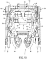
Fig. 9 is a rear perspective view of the stroller frame inFig. 1 , showing the stroller frame being folded; and -
Fig. 10 is a rear side view of the stroller frame inFig. 1 , showing the stroller frame being folded. - With reference to
Figs. 1 to 3 , and5 , a stroller frame in accordance with the present invention comprises abody 1, twofront wheel assemblies 2, aseat supporting mechanism 3, and a rearwheel folding mechanism 4. - With reference to
Figs. 1 to 5 , thebody 1 has a front end having two sides, a rear side, afront wheel bracket 10, two firstjoint assemblies 12A, aseat supporting bracket 11, aseat plate 111, twoinclined rods 13, two secondjoint assemblies 12B, ahandle 14, a firsttransverse rod 16, a secondtransverse rod 17, and alinkage shaft 121. - The
front wheel bracket 10 has a front, a rear, a top, and twotop portions 101. The twotop portions 101 are disposed at a spaced interval and are inclined toward the top of thefront wheel bracket 10 from the front of thefront wheel bracket 10 to the rear of thefront wheel bracket 10. The two firstjoint assemblies 12A are respectively disposed on the twotop portions 101 of thefront wheel bracket 10. Theseat supporting bracket 11 is disposed on the two firstjoint assemblies 12A. Theseat plate 111 is disposed on theseat supporting bracket 11 and has a middle section and a rear section. The twoinclined rods 13 are respectively disposed on the two firstjoint assemblies 12A. The two secondjoint assemblies 12B are respectively disposed on the twoinclined rods 13. - The
handle 14 is disposed across the two secondjoint assemblies 12B and has twolongitudinal portions 142 and atransverse portion 141. The twolongitudinal portions 142 are respectively disposed on the two secondjoint assemblies 12B. Thetransverse portion 141 is disposed across the twolongitudinal portions 142 and has an operatingassembly 15 disposed on thetransverse portion 141. The operatingassembly 15 controls the two firstjoint assemblies 12A and the two secondjoint assemblies 12B. The firsttransverse rod 16 is disposed across the two firstjoint assemblies 12A below theseat supporting bracket 11. The secondtransverse rod 17 is disposed across the twotop portions 101 of thefront wheel bracket 10 below theseat supporting bracket 11, is parallel with the firsttransverse rod 16, is located ahead and below the firsttransverse rod 16, and has two ends. Thelinkage shaft 121 is disposed below the rear section of theseat plate 111, and is linkingly connected between the two firstjoint assemblies 12A. - The two first
joint assemblies 12A and the two secondjoint assemblies 12B are controlled by the operatingassembly 15. The two firstjoint assemblies 12A have both clutch-controlling and rotation functions. The two secondjoint assemblies 12B also have both clutch-controlling and rotation functions. Thebody 1 can be folded and expanded. The firstjoint assemblies 12A, the secondjoint assemblies 12B, and the operatingassembly 15 can be selected from the known folding joint assemblies. - With reference to
Figs. 1 ,3 ,4 , and5 , thebody 1 has two retractable supportingassemblies 18. Each retractable supportingassembly 18 is connected between one of the twoinclined rods 13 and theseat supporting bracket 11, and has a first supportingrod 181 and a second supportingrod 182. The first supportingrod 181 and the second supportingrod 182 are curved rods. An end of the first supportingrod 181 is pivotally disposed on a corresponding one of the twoinclined rods 13. An arc-shapedelongated hole 1811 is formed through a side surface of the first supportingrod 181. An end of the second supportingrod 182 is pivotally disposed on a side of theseat supporting bracket 11. The other end of the second supportingrod 182 is moveably connected to the other end of the first supportingrod 181. A limitingelement 1821 is disposed on the other end of the second supportingrod 182, and is inserted into the arc-shapedelongated hole 1811 for limiting a relative moving distance between the first supportingrod 181 and the second supportingrod 182. - With reference to
Figs. 1 ,3 ,4 , and5 , the twofront wheel assemblies 2 are disposed in front of thefront wheel bracket 10 and are respectively and pivotally disposed on the two sides of the front end of thebody 10. Eachfront wheel assembly 2 has afront wheel seat 20 and afront wheel 21. Thefront wheel seat 20 is pivotally disposed on a bottom-front of one of thefront portions 102 of thebody 10 for rotating to change a direction of thefront wheel seat 20. Thefront wheel 21 is pivotally disposed on thefront wheel seat 20. - With reference to
Figs. 1 ,3 ,4 , and5 , theseat supporting mechanism 3 is moveably disposed on thebody 1, is connected to a middle section of a bottom of theseat plate 111, and is connected between the firsttransverse rod 16 and the secondtransverse rod 17. Theseat supporting mechanism 3 has a first arc-shapedplate 31, a second arc-shapedplate 32, and a supportingplate 33. A top end of the first arc-shapedplate 31 is pivotally disposed on the middle section of the bottom of theseat plate 111. A bottom end of the second arc-shapedplate 32 is pivotally disposed on the secondtransverse rod 17. A top end of the supportingplate 33 is connected to thelinkage shaft 121. A bottom end of the first arc-shapedplate 31, a top end of the second arc-shapedplate 32, and a bottom end of the supportingplate 33 are connected with a pivotingshaft 34. The first arc-shapedplate 31 has a limitingportion 311. The limitingportion 311 is disposed on the bottom end of the first arc-shapedplate 31, is located below the pivotingshaft 34, and is located at an outer side of the top end of the second arc-shapedplate 32 to form a foldable multi-point supporting mechanism. - With reference to
Figs. 2 ,3 ,5 , and6 , the rearwheel folding mechanism 4 is disposed on the rear side of thebody 1 behind thefront wheels 21. The rearwheel folding mechanism 4 has tworear wheel assemblies 40 and twolinkage assemblies 50. - With reference to
Figs. 2 ,3 ,5 , and6 , the tworear wheel assemblies 40 are moveably disposed on the rear side of thebody 1. Eachrear wheel assembly 40 has arear wheel seat 42, arear wheel 41, a connectingrod 43, and a connectingseat 44. Therear wheel seat 42 has a top portion and a side. Therear wheel 41 has a wheel shaft with which the rear wheel is pivotally disposed on the side of therear wheel seat 42. The wheel shaft has a central line defined on the wheel shaft. The connectingrod 43 is securely disposed on the top portion of therear wheel seat 42. The connectingrod 43 has a central line and a top end. The central line of the connectingrod 43 is defined along a longitudinal direction of the connectingrod 43. An angle is defined between the central line of the connectingrod 43 and the central line of the wheel shaft and is an acute angle. The connectingseat 44 is pivotally disposed on the top end of the connectingrod 43, is obliquely and securely mounted on the firsttransverse rod 16 of thebody 1, and has a pivotingportion 441, a fixingportion 442, and a stoppingportion 443. The pivotingportion 441 is pivotally disposed on the top end of the connectingrod 43 by a pivoting pin and has a top end and a bottom end. The fixingportion 442 is formed on the top end of the pivotingportion 441. The connectingseat 44 is securely mounted on the firsttransverse rod 16 of thebody 1 by the fixingportion 442. The stoppingportion 443 is formed on the bottom end of the pivotingportion 441 and is located behind the top end of the connectingrod 43 for limiting a backward rotating angle between the connectingrod 43 and the connectingseat 44. - With reference to
Figs. 2 ,3 ,5 , and6 , the connectingseats 44 of the tworear wheel assemblies 40 are inclined outwardly from top to bottom of thebody 1 and are located between the two secondjoint assemblies 12B of thebody 1. The two connectingrods 43 are symmetrical and are splayed from top to bottom of thebody 1 by the connectingseats 44, respectively. When the tworear wheel assemblies 40 are expanded, the two connectingrods 43 of the tworear wheel assemblies 40 are inclined and extend from a front-top direction to a rear-bottom direction of thebody 1. Spacing between the two connectingrods 43 is progressively increased downwardly. Spacing between bottom ends of the two connectingrods 43 is larger than spacing between the top ends of the two connectingrods 43. A distance between the tworear wheels 41 is larger than a distance between the twofront wheels 21. When the tworear wheel assemblies 40 are folded, the distance between the tworear wheels 41 is smaller than the distance between the twofront wheels 21. The tworear wheels 41 are moved between the twofront wheels 21 by the connectingseats 42 inclined and the two connectingrods 43 splayed. - With reference to
Figs. 2 ,3 ,5 , and6 , the stroller frame has aflexible strap 45. Two ends of theflexible strap 45 are respectively connected to middle sections of the connectingrods 43 of the tworear wheel assemblies 40. An extending range of the two connectingrods 43 is limited by theflexible strap 45. The stroller frame has twolocking devices 60. The twolocking devices 60 are respectively disposed on the rear wheel seats 42 of the tworear wheel assemblies 40 for selectively locking the tworear wheels 41. Acable 62 is flexible and is connected to the twolocking devices 60 to link the twolocking devices 60. Apedal 61 is disposed on one of the twolocking devices 60 for controlling the twolocking devices 60. The twolocking devices 60 are linked by thecable 62. Thelocking devices 60 can be selected from the known locking devices. - With reference to
Figs. 2 ,3 ,5 , and6 , the twolinkage assemblies 50 are respectively disposed on the two ends of the secondtransverse rod 17, are respectively located at outer sides of the connectingrods 43, and are connected to the connectingrods 43 of the tworear wheel assemblies 40. Eachlinkage assembly 50 has afirst linkage rod 51, asecond linkage rod 52, a firstmulti-directional connector 53, and a secondmulti-directional connector 54. An end of thefirst linkage rod 51 is connected to the secondtransverse rod 17. The other end of thefirst linkage rod 51 is combined to the firstmulti-directional connector 53 to connect to an end of thesecond linkage rod 52. The other end of thesecond linkage rod 52 is combined to the secondmulti-directional connector 54 to connect to the middle section of a corresponding one of the connectingrods 43. - The first
multi-directional connector 53 is connected to thefirst linkage rod 51 and thesecond linkage rod 52. The secondmulti-directional connector 54 is connected to thesecond linkage rod 52 and a corresponding connectingrod 43. The tworear wheel assemblies 40 can be expanded backwardly and folded forwardly with respect to thebody 1. The tworear wheel assemblies 40 can be left-right expanded and folded. - With reference to
Figs. 1 to 3 , when the stroller frame is expanded, theinclined rods 13 of thebody 1 are extended upwardly by the two firstjoint assemblies 12A. Thehandle 14 is extended upwardly by the two secondjoint assemblies 12B. The two retractable supportingassemblies 18 are respectively extended and provide stable supporting strength to theseat plate 111 by theseat supporting bracket 11. Thebody 1 is in a steady expanded state. - With reference to
Figs. 1 to 6 , when the stroller frame is expanded, the rearwheel folding mechanism 4 is located at a back of thebody 1. The tworear wheel assemblies 40 of the rearwheel folding mechanism 4 are extended backwardly. The two connectingrods 43 are respectively guided by the two connectingseats 44 to extend backwardly and outwardly. The distance between the tworear wheels 41 is larger than the distance between the twofront wheels 21. The twolinkage assemblies 50 are connected to two ends of the secondtransverse rod 17 and the middle sections of the connectingrods 43 of the tworear wheel assemblies 40 to form an extended state and support the connectingrods 43. In eachrear wheel assembly 40, the stoppingportion 443 located at a rear side of a bottom end of the connectingseat 44 abuts a corresponding connectingrod 43 for positioning and support. - In addition, the
seat supporting mechanism 3 is located on thebody 1 and is connected to a bottom section of theseat plate 111, thelinkage shaft 121, the firsttransverse rod 16, and the secondtransverse rod 17. The limitingportion 311 on the bottom end of the first arc-shapedplate 31 is located on the top end of the second arc-shapedplate 32 for stopping and limiting to form a foldable multi-point supporting mechanism to provide stable auxiliary strength to theseat plate 111. The rearwheel folding mechanism 4 is expanded steadily. The stroller frame can be pushed and moves steadily. - With reference to
Figs. 8 to 10 , when the stroller frame is folded, the two firstjoint assemblies 12A and the two secondjoint assemblies 12B can be shifted to a foldable state by the operatingassembly 15 of thehandle 14. The twoinclined rods 13 of thebody 1 can be folded forwardly by the two firstjoint assemblies 12A, and are moved to combine with the twotop portions 101 of thefront wheel bracket 10. Thehandle 14 is folded reversely by the two secondjoint assemblies 12B. The twoinclined rods 13 are moved close to each other. In a folding process of thebody 1, theseat supporting mechanism 3 is driven by the two firstjoint assemblies 12A located at the two sides of thelinkage shaft 121 of thebody 1 for pulling theseat supporting mechanism 3 to fold by the supportingplate 33. The first arc-shapedplate 31, the second arc-shapedplate 32, and the supporting plate33 are in a folded state. - Furthermore, the rear
wheel folding mechanism 4 is folded by the twolinkage assemblies 50 and drives the connectingrods 43 of the tworear wheel assemblies 40 to respectively rotate along the pivoting pins of the pivotingportions 441 of the connectingseats 4 for moving close to thefront wheel bracket 10. In each one of the twolinkage assemblies 50, the firstmulti-directional connector 53 is connected to thefirst linkage rod 51 and thesecond linkage rod 52. The secondmulti-directional connector 54 is connected to thesecond linkage rod 52 and a corresponding one of the two connectingrods 43. When the tworear wheel assemblies 40 are folded, the connectingrods 43 are guided and move toward a middle direction of the rearwheel folding mechanism 4. The tworear wheels 41 can move to be disposed between the twofront wheels 21. The overall width and volume of the folded stroller frame are decreased.
Claims (6)
- A stroller frame, characterized in that the stroller frame comprises:a body (10) havinga front end having two sides;a rear side;a front wheel bracket (10) havinga front;a rear;a top; andtwo top portions (102) disposed at a spaced interval and inclined toward the top of the front wheel bracket (10) from the front of the front wheel bracket (10) to the rear of the front wheel bracket (10);two first joint assemblies (12A) respectively disposed on the two top portions (102) of the front wheel bracket (10);a seat supporting bracket (11) disposed on the two first joint assemblies (12A);a seat plate (111) disposed on the seat supporting bracket (11) and having a middle section and a rear section;two inclined rods (13) respectively disposed on the two first joint assemblies (12A);two second joint assemblies (12B) respectively disposed on the two inclined rods (13);a handle (14) disposed across the two second joint assemblies (12B) and havingtwo longitudinal portions (142) respectively disposed on the two second joint assemblies (12B); anda transverse portion (141) disposed across the two longitudinal portions (142) and having an operating assembly (15) disposed on the transverse portion (141), wherein the operating assembly (15) controls the two first joint assemblies (12A) and the two second joint assemblies (12B);a first transverse rod (16) disposed across the two first joint assemblies (12A) below the seat supporting bracket (11);a second transverse rod (17) disposed across the two top portions (102) of the front wheel bracket (10) below the seat supporting bracket (11), parallel with the first transverse rod (16), located ahead and below the first transverse rod (16), and having two ends; anda linkage shaft (121) disposed below the rear section of the seat plate (111), and linkingly connected between the two first joint assemblies (12A);two front wheel assemblies (2) respectively and pivotally disposed on the two sides of the front end of the body (10), and each front wheel assembly (2) havinga front wheel seat (20) pivotally disposed on the body (10); anda front wheel (21) pivotally disposed on the front wheel seat (20);a seat supporting mechanism (3) moveably disposed below the seat plate (111) of the body (10), and having a first arc-shaped plate (31), a second arc-shaped plate (32), and a supporting plate (33), a top end of the first arc-shaped plate (31) pivotally disposed on the middle section of the seat plate (111), a bottom end of the second arc-shaped plate (32) pivotally disposed on the second transverse rod (17), a top end of the supporting plate (33) connected to the linkage shaft (121), and a bottom end of the first arc-shaped plate (31), a top end of the second arc-shaped plate (32), and a bottom end of the supporting plate (33) connected with each other by a pivoting shaft (34); anda rear wheel folding mechanism (4) disposed on the rear side of the body (10), and havingtwo rear wheel assemblies (40) moveably disposed on the first transverse rod (16) of the body (10), and each rear wheel assembly (40) havinga rear wheel seat (42) having a top portion and a side;a rear wheel (41) having a wheel shaft pivotally disposed on the side of the rear wheel seat (42), and the wheel shaft having a longitudinal direction and a central line defined along the longitudinal direction of the wheel shaft;a connecting rod (43) securely disposed on the top portion of the rear wheel seat (42) and having a longitudinal direction, a central line defined along the longitudinal direction of the connecting rod (43), and a top end, wherein an angle is defined between the central line of the connecting rod (43) and the central line of the wheel shaft and is an acute angle; anda connecting seat (44) pivotally disposed on the top end of the connecting rod (43), obliquely and securely mounted on the first transverse rod (16), and havinga pivoting portion (441) pivotally disposed on the top end of the connecting rod (43) by a pivoting pin and having a top end and a bottom end;a fixing portion (442) formed on the top end of the pivoting portion (441), and the connecting seat (44) securely mounted on the first transverse rod (16) by the fixing portion (442); anda stopping portion (443) formed on the bottom end of the pivoting portion (441) and located behind the top end of the connecting rod (43) for limiting a backward rotating angle between the connecting rod (43) and the connecting seat (44);wherein the connecting seats (44) of the two rear wheel assemblies (40) are inclined outwardly from top to bottom of the body (10), and the two connecting rod (43)s are symmetrical and are splayed from top to bottom of the body (10), when the two rear wheel assemblies (40) are expanded, a distance between the two rear wheels (41) is larger than a distance between the two front wheels (21), and when the two rear wheel assemblies (40) are folded, the two rear wheels (41) move between the two front wheels (21) by the connecting seats (44) inclined and the two connecting rods (43) splayed; andtwo linkage assemblies (50) respectively disposed on the two ends of the second transverse rod (17), and respectively located at outer sides of the connecting rods (43) and connected to the connecting rods (43) of the two rear wheel assemblies (40), and each linkage assembly (50) havinga first linkage rod (51), a second linkage rod (52), a first multi-directional connector (53), and a second multi-directional connector (54), an end of the first linkage rod (51) connected to the second transverse rod (17), the other end of the first linkage rod (51) combined to the first multi-directional connector (53) to connect to an end of the second linkage rod (52), and the other end of the second linkage rod (52) combined to the second multi-directional connector (54) to connect to a middle section of a corresponding one of the connecting rods (43).
- The stroller frame as claimed in claim 1, wherein the first arc-shaped plate (31) has a limiting portion (311), the limiting portion (311) is disposed on the bottom end of the first arc-shaped plate (31), is located below the pivoting shaft (34), and is located at an outer side of the top end of the second arc-shaped plate (32).
- The stroller frame as claimed in claim 2, wherein the body (10) has two retractable supporting assemblies (18), and each retractable supporting assembly (18) is connected between one of the two inclined rods (13) and the seat supporting bracket (11) and has a first supporting rod (181) and a second supporting rod (182), the first supporting rod (181) and the second supporting rod (182) are curved rods, an end of the first supporting rod (181) is pivotally disposed on a corresponding one of the two inclined rods (13), an arc-shaped elongated hole (1811) is formed through a side surface of the first supporting rod (181), an end of the second supporting rod (182) is pivotally disposed on a side of the seat supporting bracket (11), the other end of the second supporting rod (182) is moveably connected to the other end of the first supporting rod (181), and a limiting element (1821) is disposed on the other end of the second supporting rod (182) and is inserted into the arc-shaped elongated hole (1811) for limiting a relative moving distance between the first supporting rod (181) and the second supporting rod (182).
- The stroller frame as claimed in claim 3, wherein the front wheel bracket (10) has two front portions, the two front portions are disposed on the front of the front wheel bracket (10), and the two front wheel seats (20) of the two front wheel assemblies (2) are respectively and pivotally disposed on the two front portions of the front wheel bracket (10).
- The stroller frame as claimed in any one of claims 1 to 4, wherein the stroller frame has a flexible strap (45), and two ends of the flexible strap (45) are respectively connected to the middle sections of the connecting rods (43) of the two rear wheel assemblies (40).
- The stroller frame as claimed in claim 5, wherein the stroller frame has two locking devices (60), the two locking devices (60) are respectively disposed on the rear wheel seats (42) of the two rear wheel assemblies (40) for selectively locking the two rear wheels (41), a cable (62) is connected to the two locking devices (60) to link the two locking devices (60), and a pedal (61) is disposed on one of the two locking devices (60) for controlling the two locking devices (60).
Applications Claiming Priority (1)
| Application Number | Priority Date | Filing Date | Title |
|---|---|---|---|
| CN201721000465.2U CN207328549U (en) | 2017-08-10 | 2017-08-10 | Stroller frame |
Publications (1)
| Publication Number | Publication Date |
|---|---|
| EP3441283A1 true EP3441283A1 (en) | 2019-02-13 |
Family
ID=61256719
Family Applications (1)
| Application Number | Title | Priority Date | Filing Date |
|---|---|---|---|
| EP18157935.0A Withdrawn EP3441283A1 (en) | 2017-08-10 | 2018-02-21 | Stroller frame |
Country Status (3)
| Country | Link |
|---|---|
| US (1) | US10167008B1 (en) |
| EP (1) | EP3441283A1 (en) |
| CN (1) | CN207328549U (en) |
Families Citing this family (13)
| Publication number | Priority date | Publication date | Assignee | Title |
|---|---|---|---|---|
| JP1608325S (en) * | 2017-07-12 | 2018-07-02 | ||
| CN107323511B (en) * | 2017-08-10 | 2023-06-27 | 珠海阳光儿童用品有限公司 | stroller frame |
| USD860871S1 (en) * | 2018-06-21 | 2019-09-24 | Patron Bohemia A.S. | Baby carriage |
| USD889324S1 (en) * | 2018-08-17 | 2020-07-07 | gb GmbH | Stroller for children |
| USD891993S1 (en) * | 2018-08-17 | 2020-08-04 | gb GmbH | Stroller for children |
| GB2591211B (en) * | 2018-09-18 | 2022-04-27 | Jijibaba Ltd | A push chair |
| EP3747730B1 (en) * | 2019-06-05 | 2024-07-31 | Thule Sweden AB | Foldable frame assembly and stroller |
| CN110316238B (en) * | 2019-08-08 | 2024-02-27 | 昆山威凯儿童用品有限公司 | Automatic rear wheel tread adjusting device of baby carrier |
| US11136055B2 (en) * | 2019-11-04 | 2021-10-05 | Dynamic Motion, Llc | Foldable stroller |
| CN115397715A (en) | 2020-01-29 | 2022-11-25 | 顾娃族公司 | Stroller with compact folding and suspension system |
| CN113562058B (en) * | 2021-09-13 | 2024-12-10 | 安徽呀呀乐儿童用品有限公司 | A baby stroller capable of being folded and linked |
| NL2029603B1 (en) * | 2021-11-03 | 2023-06-02 | Johannes De Haas Fortunatus | Foldable stroller |
| CN115056844B (en) * | 2022-06-13 | 2024-02-27 | 好孩子儿童用品有限公司 | Child cart |
Citations (4)
| Publication number | Priority date | Publication date | Assignee | Title |
|---|---|---|---|---|
| EP2441645A1 (en) * | 2009-06-12 | 2012-04-18 | Combi Corporation | Baby buggy |
| CN205059701U (en) * | 2015-09-18 | 2016-03-02 | 昆山威凯儿童用品有限公司 | Novel foldable bassinet frame |
| DE202017104057U1 (en) * | 2016-07-18 | 2017-07-31 | Chao-Hsi Lin | Folding stroller |
| CN107323511A (en) * | 2017-08-10 | 2017-11-07 | 中山市西区青原贸易代理服务部 | Stroller frame |
Family Cites Families (18)
| Publication number | Priority date | Publication date | Assignee | Title |
|---|---|---|---|---|
| JP3040496B2 (en) * | 1991-01-11 | 2000-05-15 | アップリカ▲葛▼西株式会社 | Folding stroller and folding mechanism used therein |
| US5472224A (en) * | 1992-04-04 | 1995-12-05 | Jane, S.A. | Foldable baby carriage frame and cradle seat couplable to same |
| TW280801B (en) * | 1994-12-26 | 1996-07-11 | Aprica Kassai Kk | |
| US5772235A (en) * | 1995-11-09 | 1998-06-30 | Graco Children's Products Inc. | Convertible stroller |
| US7044497B2 (en) * | 2000-05-08 | 2006-05-16 | Graco Children's Products Inc. | Foldable stroller |
| TW540501U (en) * | 2001-12-19 | 2003-07-01 | Link Treasure Ltd | Foldable structure for baby carriage |
| CN2690255Y (en) * | 2003-11-09 | 2005-04-06 | 中山市隆成日用制品有限公司 | Stroller folding joint structure and stroller skeleton structure |
| TWM257142U (en) * | 2003-11-12 | 2005-02-21 | Link Treasure Ltd | Frame of stroller |
| US7281732B2 (en) * | 2004-12-15 | 2007-10-16 | Evenflo Company, Inc. | Stroller with tray fold and fold latch mechanisms |
| EP1970286A1 (en) * | 2007-03-15 | 2008-09-17 | Team-Tex | Device for transporting a child |
| CA2820907C (en) * | 2012-07-10 | 2020-10-20 | Toshihiro Kikui | Stroller |
| US9399477B2 (en) * | 2012-12-27 | 2016-07-26 | Kolcraft Enterprises, Inc. | Strollers with removable child supports and related methods |
| US8991838B2 (en) * | 2013-05-23 | 2015-03-31 | Lerado (Zhong Shan) Industrial Co., Ltd. | Stroller frame with an automatic brake mechanism actuatable by hand detecting |
| US8894090B1 (en) * | 2013-11-06 | 2014-11-25 | Way-Hong Chen | Stroller with foldable structure |
| JP6236131B2 (en) * | 2015-11-23 | 2017-11-22 | 明門香港股▲フェン▼有限公司 | Infant stroller equipment |
| CN107792153B (en) * | 2016-09-06 | 2020-05-12 | 明门香港股份有限公司 | Folding structure for bicycle frame |
| CN108068869B (en) * | 2016-11-18 | 2020-04-14 | 明门香港股份有限公司 | stroller frame |
| JP6798899B2 (en) * | 2017-02-10 | 2020-12-09 | ニューウェルブランズ・ジャパン合同会社 | Wheel structure and wheelbarrow with it |
-
2017
- 2017-08-10 CN CN201721000465.2U patent/CN207328549U/en active Active
-
2018
- 2018-02-12 US US15/894,456 patent/US10167008B1/en not_active Expired - Fee Related
- 2018-02-21 EP EP18157935.0A patent/EP3441283A1/en not_active Withdrawn
Patent Citations (4)
| Publication number | Priority date | Publication date | Assignee | Title |
|---|---|---|---|---|
| EP2441645A1 (en) * | 2009-06-12 | 2012-04-18 | Combi Corporation | Baby buggy |
| CN205059701U (en) * | 2015-09-18 | 2016-03-02 | 昆山威凯儿童用品有限公司 | Novel foldable bassinet frame |
| DE202017104057U1 (en) * | 2016-07-18 | 2017-07-31 | Chao-Hsi Lin | Folding stroller |
| CN107323511A (en) * | 2017-08-10 | 2017-11-07 | 中山市西区青原贸易代理服务部 | Stroller frame |
Also Published As
| Publication number | Publication date |
|---|---|
| US10167008B1 (en) | 2019-01-01 |
| CN207328549U (en) | 2018-05-08 |
Similar Documents
| Publication | Publication Date | Title |
|---|---|---|
| US10167008B1 (en) | Stroller frame | |
| US20250136164A1 (en) | Child stroller | |
| CN105460065A (en) | Baby carriage capable of being folded in place in one step | |
| CN110816633B (en) | Child cart | |
| CN109383678B (en) | Folding stroller | |
| CN201923194U (en) | Reversing-handle baby stroller | |
| CN119117074A (en) | Strollers | |
| CN110723191B (en) | Folding baby carriage | |
| US8814183B1 (en) | Running stroller | |
| CN104417595A (en) | Linkage folding mechanism and baby carriage | |
| CN110116746A (en) | A kind of children trolley | |
| CN112319591B (en) | Child cart | |
| CN107323511B (en) | stroller frame | |
| CN110481623B (en) | Folding stroller | |
| CN206615265U (en) | Fold the small baby carriage frame of the volume of timber | |
| CN210882280U (en) | Children's barrow | |
| CN108177679A (en) | Children trolley | |
| CN217835680U (en) | Folding handcart | |
| CN112092890A (en) | a children's stroller | |
| CN207157290U (en) | A kind of three wheeled stroller | |
| US20250376207A1 (en) | Stroller | |
| CN213649705U (en) | Baby stroller capable of being folded in two directions | |
| CN110271598A (en) | A kind of children trolley | |
| CN216805566U (en) | Link gear, folding leg and shallow | |
| CN213831863U (en) | Multifunctional carriage |
Legal Events
| Date | Code | Title | Description |
|---|---|---|---|
| PUAI | Public reference made under article 153(3) epc to a published international application that has entered the european phase |
Free format text: ORIGINAL CODE: 0009012 |
|
| AK | Designated contracting states |
Kind code of ref document: A1 Designated state(s): AL AT BE BG CH CY CZ DE DK EE ES FI FR GB GR HR HU IE IS IT LI LT LU LV MC MK MT NL NO PL PT RO RS SE SI SK SM TR |
|
| AX | Request for extension of the european patent |
Extension state: BA ME |
|
| STAA | Information on the status of an ep patent application or granted ep patent |
Free format text: STATUS: THE APPLICATION IS DEEMED TO BE WITHDRAWN |
|
| 18D | Application deemed to be withdrawn |
Effective date: 20190814 |