EP3441279A1 - Rail breakage detection device - Google Patents
Rail breakage detection device Download PDFInfo
- Publication number
- EP3441279A1 EP3441279A1 EP17778818.9A EP17778818A EP3441279A1 EP 3441279 A1 EP3441279 A1 EP 3441279A1 EP 17778818 A EP17778818 A EP 17778818A EP 3441279 A1 EP3441279 A1 EP 3441279A1
- Authority
- EP
- European Patent Office
- Prior art keywords
- unit
- train
- transmission
- rail
- track circuit
- Prior art date
- Legal status (The legal status is an assumption and is not a legal conclusion. Google has not performed a legal analysis and makes no representation as to the accuracy of the status listed.)
- Granted
Links
Images


Classifications
-
- B—PERFORMING OPERATIONS; TRANSPORTING
- B61—RAILWAYS
- B61L—GUIDING RAILWAY TRAFFIC; ENSURING THE SAFETY OF RAILWAY TRAFFIC
- B61L23/00—Control, warning or like safety means along the route or between vehicles or trains
- B61L23/04—Control, warning or like safety means along the route or between vehicles or trains for monitoring the mechanical state of the route
- B61L23/042—Track changes detection
- B61L23/044—Broken rails
-
- B—PERFORMING OPERATIONS; TRANSPORTING
- B61—RAILWAYS
- B61L—GUIDING RAILWAY TRAFFIC; ENSURING THE SAFETY OF RAILWAY TRAFFIC
- B61L1/00—Devices along the route controlled by interaction with the vehicle or train
- B61L1/18—Railway track circuits
- B61L1/181—Details
-
- B—PERFORMING OPERATIONS; TRANSPORTING
- B61—RAILWAYS
- B61L—GUIDING RAILWAY TRAFFIC; ENSURING THE SAFETY OF RAILWAY TRAFFIC
- B61L23/00—Control, warning or like safety means along the route or between vehicles or trains
- B61L23/04—Control, warning or like safety means along the route or between vehicles or trains for monitoring the mechanical state of the route
-
- E—FIXED CONSTRUCTIONS
- E01—CONSTRUCTION OF ROADS, RAILWAYS, OR BRIDGES
- E01B—PERMANENT WAY; PERMANENT-WAY TOOLS; MACHINES FOR MAKING RAILWAYS OF ALL KINDS
- E01B35/00—Applications of measuring apparatus or devices for track-building purposes
-
- G—PHYSICS
- G01—MEASURING; TESTING
- G01R—MEASURING ELECTRIC VARIABLES; MEASURING MAGNETIC VARIABLES
- G01R31/00—Arrangements for testing electric properties; Arrangements for locating electric faults; Arrangements for electrical testing characterised by what is being tested not provided for elsewhere
- G01R31/50—Testing of electric apparatus, lines, cables or components for short-circuits, continuity, leakage current or incorrect line connections
-
- B—PERFORMING OPERATIONS; TRANSPORTING
- B61—RAILWAYS
- B61L—GUIDING RAILWAY TRAFFIC; ENSURING THE SAFETY OF RAILWAY TRAFFIC
- B61L1/00—Devices along the route controlled by interaction with the vehicle or train
- B61L1/18—Railway track circuits
- B61L1/181—Details
- B61L1/185—Use of direct current
-
- B—PERFORMING OPERATIONS; TRANSPORTING
- B61—RAILWAYS
- B61L—GUIDING RAILWAY TRAFFIC; ENSURING THE SAFETY OF RAILWAY TRAFFIC
- B61L1/00—Devices along the route controlled by interaction with the vehicle or train
- B61L1/18—Railway track circuits
- B61L1/181—Details
- B61L1/187—Use of alternating current
-
- B—PERFORMING OPERATIONS; TRANSPORTING
- B61—RAILWAYS
- B61L—GUIDING RAILWAY TRAFFIC; ENSURING THE SAFETY OF RAILWAY TRAFFIC
- B61L25/00—Recording or indicating positions or identities of vehicles or trains or setting of track apparatus
- B61L25/02—Indicating or recording positions or identities of vehicles or trains
- B61L25/025—Absolute localisation, e.g. providing geodetic coordinates
-
- B—PERFORMING OPERATIONS; TRANSPORTING
- B61—RAILWAYS
- B61L—GUIDING RAILWAY TRAFFIC; ENSURING THE SAFETY OF RAILWAY TRAFFIC
- B61L25/00—Recording or indicating positions or identities of vehicles or trains or setting of track apparatus
- B61L25/02—Indicating or recording positions or identities of vehicles or trains
- B61L25/026—Relative localisation, e.g. using odometer
-
- B—PERFORMING OPERATIONS; TRANSPORTING
- B61—RAILWAYS
- B61L—GUIDING RAILWAY TRAFFIC; ENSURING THE SAFETY OF RAILWAY TRAFFIC
- B61L3/00—Devices along the route for controlling devices on the vehicle or train, e.g. to release brake or to operate a warning signal
- B61L3/16—Continuous control along the route
- B61L3/22—Continuous control along the route using magnetic or electrostatic induction; using electromagnetic radiation
- B61L3/221—Continuous control along the route using magnetic or electrostatic induction; using electromagnetic radiation using track circuits
Definitions
- the present invention relates to a rail fracture detection device that can be used with rails provided with a track circuit.
- Patent Literature 1 With the conventional technology disclosed in Patent Literature 1, it is possible to, by using train positional information, distinguish between the rail fracture and the presence of a train on the rails.
- Patent Literature 1 Japanese Patent Application Laid-Open No. 2012-188009
- the present invention is made in view of the above, and an object of the present invention is to provide a rail fracture detection device capable of detecting a fracture of a rail in a track circuit without using train positional information.
- a rail fracture detection device detects a rail fracture in a section provided with a track circuit by determining presence or absence of a rail fracture and determining presence or absence of a train on a rail by using information on whether a relay of the track circuit is activated or deactivated and information on a current value of a current flowing in the track circuit.
- an effect is obtained where a fracture of a rail in a track circuit can be detected without using train positional information.
- a rail fracture detection device according to embodiments of the present invention will be described below in detail with reference to the drawings. Note that the present invention is not limited by the embodiments.
- FIG. 1 is a diagram illustrating an exemplary configuration of a rail fracture detection device according to a first embodiment of the present invention.
- a rail fracture detection device 5 illustrated in FIG. 1 includes a transmission unit 1; a reception unit 2; rails 3a and 3b to which the transmission unit 1 and the reception unit 2 are electrically connected; and a rail fracture detection unit 4.
- one section of a track circuit is illustrated in FIG. 1 , and the travelling direction of a train is in the direction from the reception unit 2 toward the transmission unit 1.
- the transmission unit 1 includes a transmission-unit power source 11; a transmission-unit resistor 12; a transmission-unit current measurement unit 13; and a transmission-unit power consumption calculation unit 14.
- the transmission-unit power source 11 is a DC power source connected in series between the rail 3a and the rail 3b.
- the transmission-unit resistor 12 is a resistor connected in series with the transmission-unit power source 11.
- the transmission-unit current measurement unit 13 measures the current flowing through the transmission-unit resistor 12 and outputs a current measurement value I.
- the current measurement value I is input to the rail fracture detection unit 4.
- the transmission-unit power consumption calculation unit 14 measures the power consumption of the transmission unit 1 and outputs a power consumption measurement value P.
- the power consumption measurement value P is calculated by multiplying the voltage of the transmission-unit power source 11 by the current measurement value I measured by the transmission-unit current measurement unit 13.
- the reception unit 2 includes a relay 21 and a reception-unit voltage measurement unit 22.
- the reception-unit voltage measurement unit 22 measures the voltage applied to the relay 21 and outputs a voltage measurement value V. In a case where the voltage applied to the relay 21 is lower than a preset threshold value, the relay 21 is deactivated, and in a case where the applied voltage is greater than or equal to the preset threshold value, the relay 21 of the track circuit is activated. In a case where power is not supplied to the reception unit 2 due to a malfunction, the relay is deactivated and a train cannot enter the section of this track circuit.
- One end of the transmission unit 1 and one end of the reception unit 2 are connected to the rail 3a, and the other end of the transmission unit 1 and the other end of the reception unit 2 are connected to the rail 3b.
- the rail fracture detection unit 4 includes a determination unit 41.
- the determination unit 41 receives the current measurement value I from the transmission-unit current measurement unit 13, the voltage measurement value V from the reception-unit voltage measurement unit 22, and the power consumption measurement value P.
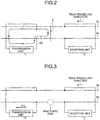
- FIG. 2 is a diagram illustrating an exemplary schematic configuration when a train is present on the rails in the section of the track circuit illustrated in FIG. 1 .
- FIG. 2 does not illustrate the train present on the rails but illustrates an axle 6 of the train present on the rails.
- the axle 6 short-circuits the rail 3a and the rail 3b.
- the current from the transmission unit 1 passes through the rail 3a and flows to the rail 3b via the axle 6.
- the current measurement value I of the transmission-unit current measurement unit 13 at this point is defined as I 2 .
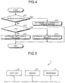
- FIG. 3 is a diagram illustrating an exemplary schematic configuration when a rail fracture occurs in the section of the track circuit illustrated in FIG. 1 .
- the current measurement value I of the transmission-unit current measurement unit 13 at this point is defined as I 3 .
- This weak current value I 3 is set as a current threshold value to perform a determination process.
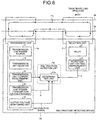
- FIG. 4 is a flowchart illustrating an exemplary operation of the determination unit 41 of the rail fracture detection unit 4 illustrated in FIG. 1 .
- the determination unit 41 determines whether the relay of the track circuit in the section that is a determination target is activated (S11).
- the voltage measurement value V of the reception-unit voltage measurement unit 22 is used to determine whether the relay of the track circuit is activated.
- the relay of the track circuit is activated.
- the relay of the track circuit is deactivated.
- the determination unit 41 determines that there is no rail fracture in the section of the track circuit and a train is not present on the rails (S12).
- the determination unit 41 determines whether the current value I of the transmission-unit current measurement unit 13 is larger than I 3 (S13).
- the determination unit 41 determines that there is no rail fracture in the section of the track circuit but a train is present on the rails (S15). In other words, when the relay is deactivated and the current value I is larger than I 3 , the determination unit 41 determines that a train is present on the rails in the track circuit. Alternatively, when the voltage measurement value V is lower than the preset voltage threshold value and the current value I is larger than I 3 , the determination unit 41 determines that a train is present on the rails in the track circuit.
- the determination unit 41 determines whether the current value I of the transmission-unit current measurement unit 13 is larger than I 3 , but the present invention is not limited thereto.
- the determination unit 41 may determine whether the current value I of the transmission-unit current measurement unit 13 is larger than a preset determination threshold value I 0 .
- the determination unit 41 can determine whether there is a rail fracture in the section of the track circuit.
- the determination unit 41 determines that there is a rail fracture, a train is stopped or the train is made to travel slowly.
- the train is stopped or the train is made to travel slowly in a manner similar to when a rail fracture is detected.
- the rail fracture detection unit 4 includes at least a processor, a memory, and an input unit, and the operation of the respective devices can be implemented by software.
- FIG. 5 is a diagram illustrating an exemplary general configuration of hardware to implement the rail fracture detection unit 4 according to the first embodiment.
- the devices illustrated in FIG. 5 include a processor 42, a memory 43, and an input unit 44.
- the processor 42 uses received data to execute calculations and control with software.
- the memory 43 stores the received data or data and software necessary for the processor 42 to execute calculations and control.
- the input unit 44 receives the current measurement value I from the transmission-unit current measurement unit 13 and the voltage measurement value V from the reception-unit voltage measurement unit 22.
- a plurality of processors 42 and a plurality of memories 43 may be provided.
- the rail fracture detection device uses information on whether the relay of the track circuit is activated or deactivated and information on the value of the current flowing through the track circuit to detect a rail fracture in the section provided with the track circuit.
- the rail fracture detection device includes: the reception unit 2 that is provided between the two rails 3a and 3b and that includes the relay 21 of the track circuit; the transmission unit 1 that is provided between the two rails 3a and 3b but is located after the reception unit 2 in the travelling direction of a train and that forms a current loop with the reception unit 2 and the two rails 3a and 3b; and the determination unit 41 to determine whether there is a fracture in the two rails 3a and 3b on the basis of the information from the reception unit 2 and the information from the transmission unit 1.
- the reception unit 2 includes the reception-unit voltage measurement unit 22 to measure the voltage applied to the relay 21.
- the transmission unit 1 includes the transmission-unit power source 11 to generate current; the transmission-unit resistor 12 connected in series with the transmission-unit power source 11; and the transmission-unit current measurement unit 13 to measure the current in the transmission-unit resistor 12.
- the determination unit 41 determines whether there is a fracture in the two rails 3a and 3b by using the current measurement value of the transmission-unit current measurement unit 13 and the voltage measurement value of the reception-unit voltage measurement unit 22.
- a fracture of a rail in a track circuit can be detected by using a voltage value of the reception unit in the track circuit and a current value of the transmission unit.
- a rail fracture can be detected even in a state when a train is not present on the rails in a track circuit.
- the first embodiment can be implemented by a simple configuration, and therefore, the first embodiment can be installed at low cost.
- the determination unit 41 detects a rail fracture by using both the current measurement value I from the transmission-unit current measurement unit 13 and the voltage measurement value V from the reception-unit voltage measurement unit 22, but the present invention is not limited thereto. It is possible to use only the current measurement value I from the transmission-unit current measurement unit 13 without using the voltage measurement value V from the reception-unit voltage measurement unit 22.
- a rail fracture is detected by using the current of the transmission unit 1 and the voltage of the reception unit 2, but a rail fracture may also be detected by calculating power consumption in the transmission unit 1 by the transmission-unit power consumption calculation unit 14 provided in the transmission unit 1.
- a DC track circuit is exemplified as the track circuit, but the present invention is not limited thereto, and an AC current track circuit may be used as the track circuit. Furthermore, the track circuit is exemplified in the first embodiment, but the present invention is not limited thereto, and an electric circuit may also be used.
- the first embodiment is preferably used in a section including a curved portion of a railroad.
- the reason is that a rail fracture is more likely to occur in a curved portion of a railroad due to the friction with the wheels. It is particularly preferable for the first embodiment to be used in a curved portion having a small radius of curvature of a railroad.
- the first embodiment is also preferably used in a section including a welded portion of a railroad.
- the reason is that a rail fracture is more likely to occur in a welded portion of a railroad.
- FIG. 6 is a diagram illustrating an exemplary configuration of a rail fracture detection device according to a second embodiment of the present invention.
- a rail fracture detection device 5a illustrated in FIG. 6 differs from the rail fracture detection device 5 illustrated in FIG. 1 in that the former includes a transmission unit 1a in place of the transmission unit 1 and includes a rail fracture detection unit 4a in place of the rail fracture detection unit 4. Any points not specifically mentioned here are referred to in the first embodiment.
- the transmission unit 1a has a configuration in which an output voltage monitoring unit 15 is added to the transmission unit 1 illustrated in FIG. 1 .
- the output voltage monitoring unit 15 monitors the output voltage of the transmission-unit power source 11, and it outputs a malfunction signal when the output voltage exceeds a preset voltage value range.
- the rail fracture detection unit 4a differs from the rail fracture detection unit 4 illustrated in FIG. 1 in that it includes a determination unit 41a to which this malfunction signal is input.
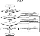
- FIG. 7 is a flowchart illustrating an exemplary operation of the determination unit 41a of the rail fracture detection unit 4a illustrated in FIG. 6 .
- the determination unit 41a determines whether a malfunction signal is received (S20). In a case where the determination unit 41a receives the malfunction signal (S20: Yes), the determination unit 41a determines that a malfunction has occurred (S21) and terminates the processing. In a case where the determination unit 41a does not receive the malfunction signal (S20: No), the determination unit 41a determines whether the relay of the track circuit in the section that is a determination target is activated (S11).
- the processing after the determination is similar to the processing of FIG. 4 in the first embodiment.
- a malfunction of the transmission-unit power source 11 can be detected in advance by monitoring the output voltage of the transmission-unit power source 11.
- FIG. 8 is a diagram illustrating an exemplary configuration of a rail fracture detection device according to a third embodiment of the present invention.
- a rail fracture detection device 5b illustrated in FIG. 8 differs from the rail fracture detection device 5a illustrated in FIG. 6 in that it includes a rail fracture detection unit 4b in place of the rail fracture detection unit 4a and it further includes a train position detection unit 7. Any points not specifically mentioned here are referred to in the first embodiment.
- the train position detection unit 7 outputs train positional information on a train present on a track including rails 3a and 3b.
- This train positional information is the train's own positional information acquired from a pulse signal from a tacho-generator and from absolute positional information from a ground coil.
- the tacho-generator is included in an on-board device mounted on the train present on the track and provided to the wheels of the train.
- the rail fracture detection unit 4b includes a determination unit 41b.
- the determination unit 41b receives the current measurement value I from the transmission-unit current measurement unit 13, the voltage measurement value V from the reception-unit voltage measurement unit 22, the power consumption measurement value P from the transmission-unit power consumption calculation unit 14, and the train positional information from the train position detection unit 7.
- FIG. 9 is a flowchart illustrating an exemplary operation of the determination unit 41b of the rail fracture detection unit 4b illustrated in FIG. 8 .
- the flowchart illustrated in FIG. 9 differs from the flowchart illustrated in FIG. 7 in the second embodiment in that in a case where it is determined that there is a fracture in the section of the track circuit (S14), a fractured part is identified (S31).
- Other processes are similar to those in FIG. 7 in the second embodiment.
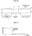
- FIG. 10 is a diagram illustrating an exemplary schematic configuration when a rail fracture occurs in the section of the track circuit illustrated in FIG. 8 .
- axles 6a and 6b of a train present on the rails are illustrated, and there is a fractured part in the rail 3b.
- the axles 6a and 6b short-circuit the rail 3a and the rail 3b, and the travelling direction of the train is in the direction from the axle 6a toward the axle 6b.
- the axle 6a is located before the fractured part in the travelling direction, i.e., on the side closer to the reception unit 2 than the fractured part
- the axle 6b is located after the fractured part in the travelling direction, i.e., on the side closer to the transmission unit 1 than the fractured part.
- FIG. 11 is a graph illustrating an exemplary relation between the current value and the axle position, where the horizontal axis represents the axle position and the vertical axis represents the current value.
- the current measurement value I of the transmission-unit current measurement unit 13 increases as illustrated by K 2 in FIG. 11 .
- the relay is deactivated and the current measurement value I of the transmission-unit current measurement unit 13 at this point is I 2 described above due to a short-circuit caused by the axle.
- the determination unit 41b of the rail fracture detection unit 4b illustrated in FIG. 8 refers to the train positional information from the train position detection unit 7, and then identifies, as a place of fracture, the position of the axle of the train at which the current measurement value I increases.
- the rail fracture detection device includes the train position detection unit that acquires positional information from a train on the track circuit and outputs train positional information, and the determination unit identifies a fractured part of the rail on the basis of the train positional information and the current value or current measurement value.
- the determination unit identifies, as the place of fracture, the position of the axle of the train at which the current measurement value I increases.
- the rail fracture detection device may include the transmission unit 1 in place of the transmission unit 1a.
Landscapes
- Engineering & Computer Science (AREA)
- Mechanical Engineering (AREA)
- Automation & Control Theory (AREA)
- Architecture (AREA)
- Civil Engineering (AREA)
- Structural Engineering (AREA)
- Physics & Mathematics (AREA)
- General Physics & Mathematics (AREA)
- Train Traffic Observation, Control, And Security (AREA)
- Investigating Or Analyzing Materials By The Use Of Electric Means (AREA)
- Geophysics And Detection Of Objects (AREA)
Abstract
Description
- The present invention relates to a rail fracture detection device that can be used with rails provided with a track circuit.
- In the conventional technologies, whether a relay of a track circuit is activated or deactivated is detected on the rails provided with the track circuit. When the relay of the track circuit is activated, it is determined that a train is not present on the rails, and when the relay of the track circuit is deactivated, it is determined that a train is present on the rails or there is a fractured part in a rail. It is thus impossible in the conventional technologies to distinguish between the presence of a train on the rails and the occurrence of a fractured part in a rail.
- With the conventional technology disclosed in
Patent Literature 1, it is possible to, by using train positional information, distinguish between the rail fracture and the presence of a train on the rails. - Patent Literature 1: Japanese Patent Application Laid-Open No.
2012-188009 - However, with the conventional technology, train positional information is necessary. Thus, both on-board information and ground information are required and cooperation between ground devices and on-board devices is required. This leads to a problem in that the system becomes complicated.
- The present invention is made in view of the above, and an object of the present invention is to provide a rail fracture detection device capable of detecting a fracture of a rail in a track circuit without using train positional information.
- In order to solve the above problems and achieve the object, a rail fracture detection device according to an aspect of the present invention detects a rail fracture in a section provided with a track circuit by determining presence or absence of a rail fracture and determining presence or absence of a train on a rail by using information on whether a relay of the track circuit is activated or deactivated and information on a current value of a current flowing in the track circuit.
- According to the present invention, an effect is obtained where a fracture of a rail in a track circuit can be detected without using train positional information.
-
-
FIG. 1 is a diagram illustrating an exemplary configuration of a rail fracture detection device according to a first embodiment. -
FIG. 2 is a diagram illustrating an exemplary schematic configuration when a train is present on the rails in a section of a track circuit illustrated inFIG. 1 . -
FIG. 3 is a diagram illustrating an exemplary schematic configuration when a rail fracture occurs in the section of the track circuit illustrated inFIG. 1 . -
FIG. 4 is a flowchart illustrating an exemplary operation of a determination unit of the rail fracture detection device according to the first embodiment. -
FIG. 5 is a diagram illustrating an exemplary general configuration of hardware to implement the rail fracture detection device according to the first embodiment. -
FIG. 6 is a diagram illustrating an exemplary configuration of a rail fracture detection device according to a second embodiment. -
FIG. 7 is a flowchart illustrating an exemplary operation of a determination unit of the rail fracture detection device according to the second embodiment. -
FIG. 8 is a diagram illustrating an exemplary configuration of a rail fracture detection device according to a third embodiment. -
FIG. 9 is a flowchart illustrating an exemplary operation of a determination unit of the rail fracture detection device according to the third embodiment. -
FIG. 10 is a diagram illustrating an exemplary schematic configuration when a rail fracture occurs in a section of a track circuit illustrated inFIG. 8 . -
FIG. 11 is a graph illustrating an exemplary relation between a current value and an axle position, where the horizontal axis represents the axle position and the vertical axis represents the current value. - A rail fracture detection device according to embodiments of the present invention will be described below in detail with reference to the drawings. Note that the present invention is not limited by the embodiments.
-
FIG. 1 is a diagram illustrating an exemplary configuration of a rail fracture detection device according to a first embodiment of the present invention. A railfracture detection device 5 illustrated inFIG. 1 includes atransmission unit 1; areception unit 2;rails transmission unit 1 and thereception unit 2 are electrically connected; and a rail fracture detection unit 4. Here, one section of a track circuit is illustrated inFIG. 1 , and the travelling direction of a train is in the direction from thereception unit 2 toward thetransmission unit 1. - The
transmission unit 1 includes a transmission-unit power source 11; a transmission-unit resistor 12; a transmission-unitcurrent measurement unit 13; and a transmission-unit powerconsumption calculation unit 14. The transmission-unit power source 11 is a DC power source connected in series between therail 3a and therail 3b. The transmission-unit resistor 12 is a resistor connected in series with the transmission-unit power source 11. The transmission-unitcurrent measurement unit 13 measures the current flowing through the transmission-unit resistor 12 and outputs a current measurement value I. The current measurement value I is input to the rail fracture detection unit 4. The transmission-unit powerconsumption calculation unit 14 measures the power consumption of thetransmission unit 1 and outputs a power consumption measurement value P. The power consumption measurement value P is calculated by multiplying the voltage of the transmission-unit power source 11 by the current measurement value I measured by the transmission-unitcurrent measurement unit 13. - The
reception unit 2 includes arelay 21 and a reception-unitvoltage measurement unit 22. The reception-unitvoltage measurement unit 22 measures the voltage applied to therelay 21 and outputs a voltage measurement value V. In a case where the voltage applied to therelay 21 is lower than a preset threshold value, therelay 21 is deactivated, and in a case where the applied voltage is greater than or equal to the preset threshold value, therelay 21 of the track circuit is activated. In a case where power is not supplied to thereception unit 2 due to a malfunction, the relay is deactivated and a train cannot enter the section of this track circuit. - One end of the
transmission unit 1 and one end of thereception unit 2 are connected to therail 3a, and the other end of thetransmission unit 1 and the other end of thereception unit 2 are connected to therail 3b. - The rail fracture detection unit 4 includes a
determination unit 41. Thedetermination unit 41 receives the current measurement value I from the transmission-unitcurrent measurement unit 13, the voltage measurement value V from the reception-unitvoltage measurement unit 22, and the power consumption measurement value P. - In
FIG. 1 , no train is present on the rails in the section of the track circuit. Thus, the current from thetransmission unit 1 passes through therail 3a, flows to therail 3b via thereception unit 2, passes through therail 3b, and then flows to thetransmission unit 1. The current measurement value I of the transmission-unitcurrent measurement unit 13 at this point is defined as I1. -
FIG. 2 is a diagram illustrating an exemplary schematic configuration when a train is present on the rails in the section of the track circuit illustrated inFIG. 1 .FIG. 2 does not illustrate the train present on the rails but illustrates anaxle 6 of the train present on the rails. Theaxle 6 short-circuits therail 3a and therail 3b. Thus, inFIG. 2 , the current from thetransmission unit 1 passes through therail 3a and flows to therail 3b via theaxle 6. In other words, the current is short-circuited by theaxle 6. The current measurement value I of the transmission-unitcurrent measurement unit 13 at this point is defined as I2. -
FIG. 3 is a diagram illustrating an exemplary schematic configuration when a rail fracture occurs in the section of the track circuit illustrated inFIG. 1 . InFIG. 3 , there is a fractured part in therail 3b and thus a current path is blocked inFIG. 3 and only a weak current flows. The current measurement value I of the transmission-unitcurrent measurement unit 13 at this point is defined as I3. This weak current value I3 is set as a current threshold value to perform a determination process. -
FIG. 4 is a flowchart illustrating an exemplary operation of thedetermination unit 41 of the rail fracture detection unit 4 illustrated inFIG. 1 . First, the processing is started, and thedetermination unit 41 determines whether the relay of the track circuit in the section that is a determination target is activated (S11). Here, the voltage measurement value V of the reception-unitvoltage measurement unit 22 is used to determine whether the relay of the track circuit is activated. When the voltage measurement value V is greater than or equal to a preset threshold value, the relay of the track circuit is activated. When the voltage measurement value V is lower than the preset threshold value, the relay of the track circuit is deactivated. When the relay of the track circuit is activated (S11: Yes), thedetermination unit 41 determines that there is no rail fracture in the section of the track circuit and a train is not present on the rails (S12). When the relay of the track circuit is not activated (S11: No), i.e., when the relay of the track circuit is deactivated, thedetermination unit 41 determines whether the current value I of the transmission-unitcurrent measurement unit 13 is larger than I3 (S13). When the current value I is not larger than I3 (S13: No), i.e., when the current value I=I3, thedetermination unit 41 determines that there is a fracture in the section of the track circuit (S14). When the current value I is larger than I3 (S13: Yes), thedetermination unit 41 determines that there is no rail fracture in the section of the track circuit but a train is present on the rails (S15). In other words, when the relay is deactivated and the current value I is larger than I3, thedetermination unit 41 determines that a train is present on the rails in the track circuit. Alternatively, when the voltage measurement value V is lower than the preset voltage threshold value and the current value I is larger than I3, thedetermination unit 41 determines that a train is present on the rails in the track circuit. - Note that, in S13 of
FIG. 4 , thedetermination unit 41 determines whether the current value I of the transmission-unitcurrent measurement unit 13 is larger than I3, but the present invention is not limited thereto. Thedetermination unit 41 may determine whether the current value I of the transmission-unitcurrent measurement unit 13 is larger than a preset determination threshold value I0. - As described above, the
determination unit 41 can determine whether there is a rail fracture in the section of the track circuit. - In a case where the
determination unit 41 determines that there is a rail fracture, a train is stopped or the train is made to travel slowly. - In a case where the
determination unit 41 cannot acquire the current measurement value I from the transmission-unitcurrent measurement unit 13 due to a malfunction of thetransmission unit 1 or in a case where thedetermination unit 41 cannot acquire the voltage measurement value V from the reception-unitvoltage measurement unit 22, the train is stopped or the train is made to travel slowly in a manner similar to when a rail fracture is detected. - Note that, in the first embodiment, the rail fracture detection unit 4 includes at least a processor, a memory, and an input unit, and the operation of the respective devices can be implemented by software.
FIG. 5 is a diagram illustrating an exemplary general configuration of hardware to implement the rail fracture detection unit 4 according to the first embodiment. The devices illustrated inFIG. 5 include aprocessor 42, a memory 43, and aninput unit 44. Theprocessor 42 uses received data to execute calculations and control with software. The memory 43 stores the received data or data and software necessary for theprocessor 42 to execute calculations and control. Theinput unit 44 receives the current measurement value I from the transmission-unitcurrent measurement unit 13 and the voltage measurement value V from the reception-unitvoltage measurement unit 22. A plurality ofprocessors 42 and a plurality of memories 43 may be provided. - As described above, the rail fracture detection device according to the first embodiment uses information on whether the relay of the track circuit is activated or deactivated and information on the value of the current flowing through the track circuit to detect a rail fracture in the section provided with the track circuit. Specifically, the rail fracture detection device according to the first embodiment includes: the
reception unit 2 that is provided between the tworails relay 21 of the track circuit; thetransmission unit 1 that is provided between the tworails reception unit 2 in the travelling direction of a train and that forms a current loop with thereception unit 2 and the tworails determination unit 41 to determine whether there is a fracture in the tworails reception unit 2 and the information from thetransmission unit 1. Thereception unit 2 includes the reception-unitvoltage measurement unit 22 to measure the voltage applied to therelay 21. Thetransmission unit 1 includes the transmission-unit power source 11 to generate current; the transmission-unit resistor 12 connected in series with the transmission-unit power source 11; and the transmission-unitcurrent measurement unit 13 to measure the current in the transmission-unit resistor 12. Thedetermination unit 41 determines whether there is a fracture in the tworails current measurement unit 13 and the voltage measurement value of the reception-unitvoltage measurement unit 22. - With the conventional technology, whether a relay of a track circuit is activated or deactivated is detected, and in a case where the relay of the track circuit is activated, it is determined that a train is not present on the rails, and in a case where the relay of the track circuit is deactivated, it is determined that a train is present on the rails or there is a fractured part in a rail. It is therefore not possible to distinguish between when a train is present on the rails and when there is a fractured part in a rail.
- Accordingly, with the conventional technology, in the case where the relay of the track circuit is deactivated, it is possible to distinguish between when a train is present on the rails and when there is a fractured part in a rail by referring to train positional information and determining whether the train positional information is included in the track circuit. However, with such a technology, it is necessary to refer to the train positional information that is on-board information and thus both the on-board information and ground information are required. Thus, there is a problem in that the system becomes complicated. Additionally, the train positional information detected on the train is affected by idling or slippage of the wheels of the train, and therefore, there is a problem in that the train positional information lacks accuracy.
- According to the first embodiment, a fracture of a rail in a track circuit can be detected by using a voltage value of the reception unit in the track circuit and a current value of the transmission unit. Thus, it is possible to detect a fracture of a rail in the track circuit only by using the information on the ground side without referring to the train positional information that is on-board information. Therefore, a fracture of a rail in the track circuit can be detected without any cooperation between a ground device and an on-board device.
- Additionally, it is also possible to detect a rail fracture by using a return current. However, in a case where the return current is used, it is necessary that a train be in a power running operation or in a regenerative operation. According to the first embodiment, a rail fracture can be detected even in a state when a train is not present on the rails in a track circuit.
- Furthermore, the first embodiment can be implemented by a simple configuration, and therefore, the first embodiment can be installed at low cost.
- In the above description, the
determination unit 41 detects a rail fracture by using both the current measurement value I from the transmission-unitcurrent measurement unit 13 and the voltage measurement value V from the reception-unitvoltage measurement unit 22, but the present invention is not limited thereto. It is possible to use only the current measurement value I from the transmission-unitcurrent measurement unit 13 without using the voltage measurement value V from the reception-unitvoltage measurement unit 22. In other words, because the current measurement value I=I1 in a case where a train is not present on the rails within the section of the track circuit, the current measurement value I=I2 in a case where a train is present on the rails in the section of the track circuit, and the current measurement value I=I3 in a case where a rail fracture occurs are different values, the presence of a train on the rails, the absence of a train on the rails, and the occurrence of a rail fracture can be distinguished from each other by focusing on such differences between the current measurement values. Here, in the case where a train is present on the rails in the section of the track circuit, the current is large because the current path is short-circuited by theaxle 6, but in a case where no train is present on the rails in the section of the track circuit, the current path is not short-circuited and passes through thereception unit 2. Therefore, the relationship I2>I1 holds. - In the first embodiment, a rail fracture is detected by using the current of the
transmission unit 1 and the voltage of thereception unit 2, but a rail fracture may also be detected by calculating power consumption in thetransmission unit 1 by the transmission-unit powerconsumption calculation unit 14 provided in thetransmission unit 1. - In the first embodiment, a DC track circuit is exemplified as the track circuit, but the present invention is not limited thereto, and an AC current track circuit may be used as the track circuit. Furthermore, the track circuit is exemplified in the first embodiment, but the present invention is not limited thereto, and an electric circuit may also be used.
- Note that the first embodiment is preferably used in a section including a curved portion of a railroad. The reason is that a rail fracture is more likely to occur in a curved portion of a railroad due to the friction with the wheels. It is particularly preferable for the first embodiment to be used in a curved portion having a small radius of curvature of a railroad.
- The first embodiment is also preferably used in a section including a welded portion of a railroad. The reason is that a rail fracture is more likely to occur in a welded portion of a railroad.
-
FIG. 6 is a diagram illustrating an exemplary configuration of a rail fracture detection device according to a second embodiment of the present invention. A railfracture detection device 5a illustrated inFIG. 6 differs from the railfracture detection device 5 illustrated inFIG. 1 in that the former includes atransmission unit 1a in place of thetransmission unit 1 and includes a railfracture detection unit 4a in place of the rail fracture detection unit 4. Any points not specifically mentioned here are referred to in the first embodiment. - The
transmission unit 1a has a configuration in which an outputvoltage monitoring unit 15 is added to thetransmission unit 1 illustrated inFIG. 1 . The outputvoltage monitoring unit 15 monitors the output voltage of the transmission-unit power source 11, and it outputs a malfunction signal when the output voltage exceeds a preset voltage value range. The railfracture detection unit 4a differs from the rail fracture detection unit 4 illustrated inFIG. 1 in that it includes adetermination unit 41a to which this malfunction signal is input. -
FIG. 7 is a flowchart illustrating an exemplary operation of thedetermination unit 41a of the railfracture detection unit 4a illustrated inFIG. 6 . First, the processing is started, and thedetermination unit 41a determines whether a malfunction signal is received (S20). In a case where thedetermination unit 41a receives the malfunction signal (S20: Yes), thedetermination unit 41a determines that a malfunction has occurred (S21) and terminates the processing. In a case where thedetermination unit 41a does not receive the malfunction signal (S20: No), thedetermination unit 41a determines whether the relay of the track circuit in the section that is a determination target is activated (S11). The processing after the determination is similar to the processing ofFIG. 4 in the first embodiment. - According to the second embodiment, a malfunction of the transmission-
unit power source 11 can be detected in advance by monitoring the output voltage of the transmission-unit power source 11. -
FIG. 8 is a diagram illustrating an exemplary configuration of a rail fracture detection device according to a third embodiment of the present invention. A railfracture detection device 5b illustrated inFIG. 8 differs from the railfracture detection device 5a illustrated inFIG. 6 in that it includes a railfracture detection unit 4b in place of the railfracture detection unit 4a and it further includes a trainposition detection unit 7. Any points not specifically mentioned here are referred to in the first embodiment. - The train
position detection unit 7 outputs train positional information on a train present on atrack including rails - The rail
fracture detection unit 4b includes adetermination unit 41b. Thedetermination unit 41b receives the current measurement value I from the transmission-unitcurrent measurement unit 13, the voltage measurement value V from the reception-unitvoltage measurement unit 22, the power consumption measurement value P from the transmission-unit powerconsumption calculation unit 14, and the train positional information from the trainposition detection unit 7. -
FIG. 9 is a flowchart illustrating an exemplary operation of thedetermination unit 41b of the railfracture detection unit 4b illustrated inFIG. 8 . The flowchart illustrated inFIG. 9 differs from the flowchart illustrated inFIG. 7 in the second embodiment in that in a case where it is determined that there is a fracture in the section of the track circuit (S14), a fractured part is identified (S31). Other processes are similar to those inFIG. 7 in the second embodiment. -
FIG. 10 is a diagram illustrating an exemplary schematic configuration when a rail fracture occurs in the section of the track circuit illustrated inFIG. 8 . InFIG. 10 ,axles rail 3b. Theaxles rail 3a and therail 3b, and the travelling direction of the train is in the direction from theaxle 6a toward theaxle 6b. Theaxle 6a is located before the fractured part in the travelling direction, i.e., on the side closer to thereception unit 2 than the fractured part, and theaxle 6b is located after the fractured part in the travelling direction, i.e., on the side closer to thetransmission unit 1 than the fractured part. -
FIG. 11 is a graph illustrating an exemplary relation between the current value and the axle position, where the horizontal axis represents the axle position and the vertical axis represents the current value. First, when a train is present at the position of theaxle 6a, because the position of the axle is between K0 and K2, the voltage measurement value V is lower than a preset threshold value. Thus, the relay is deactivated and the current measurement value I of the transmission-unitcurrent measurement unit 13 at this point is the weak current I3 as described above. With this current detection, it can be determined that there is a fractured part in the track circuit. - Then, when a train travels toward the position of the
axle 6b and the axle passes the fractured part, the current measurement value I of the transmission-unitcurrent measurement unit 13 increases as illustrated by K2 inFIG. 11 . - After that, when the train is present at the position of the
axle 6b, because the position of the axle is between K2 and K1, the voltage measurement value V is lower than the preset threshold value. Thus, the relay is deactivated and the current measurement value I of the transmission-unitcurrent measurement unit 13 at this point is I2 described above due to a short-circuit caused by the axle. - The
determination unit 41b of the railfracture detection unit 4b illustrated inFIG. 8 refers to the train positional information from the trainposition detection unit 7, and then identifies, as a place of fracture, the position of the axle of the train at which the current measurement value I increases. - As described above, the rail fracture detection device according to the third embodiment includes the train position detection unit that acquires positional information from a train on the track circuit and outputs train positional information, and the determination unit identifies a fractured part of the rail on the basis of the train positional information and the current value or current measurement value. Here, the determination unit identifies, as the place of fracture, the position of the axle of the train at which the current measurement value I increases.
- Note that the rail fracture detection device according to the third embodiment may include the
transmission unit 1 in place of thetransmission unit 1a. - Note that the configurations described in the first to third embodiments are exemplary content of the present invention and can be combined with another known technology, and furthermore, part of the configurations can be omitted or modified within the scope without departing from the spirit of the present invention.
- 1, 1a transmission unit; 2 reception unit; 3a, 3b rail; 4, 4a, 4b rail fracture detection unit; 5, 5a, 5b rail fracture detection device; 6, 6a, 6b axle; 7 train position detection unit; 11 transmission-unit power source; 12 transmission-unit resistor; 13 transmission-unit current measurement unit; 14 transmission-unit power consumption calculation unit; 15 output voltage monitoring unit; 21 relay; 22 reception-unit voltage measurement unit; 41, 41a, 41b determination unit; 42 processor; 43 memory; 44 input unit.
Claims (10)
- A rail fracture detection device to detect a rail fracture in a section provided with a track circuit by determining presence or absence of a rail fracture and determining presence or absence of a train on a rail by using information on whether a relay of the track circuit is activated or deactivated and information on a current value of a current flowing in the track circuit.
- The rail fracture detection device according to claim 1, wherein in a case where the relay is deactivated and the current value is larger than a threshold value, it is determined that a train is present on a rail in the track circuit.
- The rail fracture detection device according to claim 1 or 2, comprising a transmission unit that is provided between two rails but is located after a reception unit including the relay of the track circuit in a travelling direction of a train and that forms a current loop with,the reception unit and the two rails, wherein
the transmission unit includes a power consumption calculation unit to calculate a power consumption on a basis of a voltage value of a transmission-unit power source and a current value of a current flowing in a transmission-unit resistor. - The rail fracture detection device according to any one of claims 1 to 3, comprising a train position detection unit to acquire positional information from a train on the track circuit and output train positional information, wherein
a rail fractured part is identified on a basis of the train positional information and the current value. - A rail fracture detection device comprising:a reception unit provided between two rails and including a relay of a track circuit;a transmission unit that is provided between the two rails but is located after the reception unit in a travelling direction of a train and that forms a current loop with the reception unit and the two rails; anda determination unit to determine presence or absence of a fracture in the two rails and presence or absence of a train on the rails on a basis of information from the reception unit and information from the transmission unit, whereinthe reception unit includes a reception-unit voltage measurement unit to measure a voltage applied to the relay,the transmission unit includesa transmission-unit power source to generate the current,a transmission-unit resistor connected in series with the transmission-unit power source, anda transmission-unit current measurement unit to measure a current in the transmission-unit resistor, andthe determination unit determines a fracture in the two rails by using a current measurement value of the transmission-unit current measurement unit and a voltage measurement value of the reception-unit voltage measurement unit.
- The rail fracture detection device according to claim 5, wherein in a case where the voltage measurement value is lower than a preset voltage threshold value and the current measurement value is larger than a current threshold value, it is determined that a train is present on the rails in the track circuit.
- The rail fracture detection device according to claim 5 or 6, wherein the transmission unit includes a power consumption calculation unit to calculate a power consumption on a basis of a voltage value of the transmission-unit power source and a current value of a current flowing in the transmission-unit resistor.
- The rail fracture detection device according to any one of claims 5 to 7, comprising a train position detection unit to acquire positional information from a train on the track circuit and output train positional information, wherein
the determination unit identifies a rail fractured part on a basis of the train positional information and the current measurement value. - The rail fracture detection device according to any one of claims 1 to 8, wherein the track circuit is provided in a section including a curved portion of a railroad.
- The rail fracture detection device according to any one of claims 1 to 8, wherein the track circuit is provided in a section including a welded portion of a railroad.
Applications Claiming Priority (2)
| Application Number | Priority Date | Filing Date | Title |
|---|---|---|---|
| PCT/JP2016/061037 WO2017175277A1 (en) | 2016-04-04 | 2016-04-04 | Rail breakage detection device |
| PCT/JP2017/001131 WO2017175439A1 (en) | 2016-04-04 | 2017-01-13 | Rail breakage detection device |
Publications (3)
| Publication Number | Publication Date |
|---|---|
| EP3441279A1 true EP3441279A1 (en) | 2019-02-13 |
| EP3441279A4 EP3441279A4 (en) | 2019-07-31 |
| EP3441279B1 EP3441279B1 (en) | 2023-04-26 |
Family
ID=60000330
Family Applications (1)
| Application Number | Title | Priority Date | Filing Date |
|---|---|---|---|
| EP17778818.9A Active EP3441279B1 (en) | 2016-04-04 | 2017-01-13 | Rail breakage detection device |
Country Status (5)
| Country | Link |
|---|---|
| US (1) | US10946879B2 (en) |
| EP (1) | EP3441279B1 (en) |
| JP (1) | JP6448853B2 (en) |
| ES (1) | ES2945735T3 (en) |
| WO (2) | WO2017175277A1 (en) |
Families Citing this family (9)
| Publication number | Priority date | Publication date | Assignee | Title |
|---|---|---|---|---|
| CN107985344B (en) * | 2017-10-19 | 2021-02-09 | 北京全路通信信号研究设计院集团有限公司 | Broken rail detection method and device |
| CN107914737B (en) * | 2017-10-19 | 2021-02-09 | 北京全路通信信号研究设计院集团有限公司 | Broken rail detection method and device |
| CN108819986B (en) * | 2018-05-31 | 2020-09-29 | 北京全路通信信号研究设计院集团有限公司 | System and method for fault detection of track line |
| WO2020021672A1 (en) | 2018-07-26 | 2020-01-30 | 三菱電機株式会社 | Rail breakage detection device and rail breakage result management system |
| CN109849964A (en) * | 2019-03-29 | 2019-06-07 | 山西润泽丰科技开发有限公司 | A kind of rail joint clamping plate fracture on-Line Monitor Device and its monitoring method |
| JP7303705B2 (en) * | 2019-09-03 | 2023-07-05 | 東日本旅客鉄道株式会社 | Rail break detector |
| CN112114275B (en) * | 2020-09-14 | 2024-11-22 | 交控科技股份有限公司 | Track status detection method and system |
| JP7604266B2 (en) | 2021-02-26 | 2024-12-23 | 大同信号株式会社 | Rail breakage detection device |
| WO2024024274A1 (en) * | 2022-07-29 | 2024-02-01 | 株式会社日立製作所 | Rail breakage detection system and rail breakage detection method |
Family Cites Families (15)
| Publication number | Priority date | Publication date | Assignee | Title |
|---|---|---|---|---|
| DE3738696C2 (en) * | 1987-11-14 | 1998-05-14 | Sel Alcatel Ag | Method and device for locating a broken rail |
| JPH04133601A (en) * | 1990-09-21 | 1992-05-07 | Toshiba Corp | Automatic operation controller having protective function |
| JP2936023B2 (en) * | 1991-07-03 | 1999-08-23 | 東日本旅客鉄道株式会社 | Monitoring system for train track detection in track circuits |
| US5417388A (en) | 1993-07-15 | 1995-05-23 | Stillwell; William R. | Train detection circuit |
| US5680054A (en) * | 1996-02-23 | 1997-10-21 | Chemin De Fer Qns&L | Broken rail position detection using ballast electrical property measurement |
| US6102340A (en) * | 1997-02-07 | 2000-08-15 | Ge-Harris Railway Electronics, Llc | Broken rail detection system and method |
| JP4168316B2 (en) * | 2001-07-02 | 2008-10-22 | 株式会社日立製作所 | Track circuit device |
| JP4226400B2 (en) * | 2003-07-17 | 2009-02-18 | 本田技研工業株式会社 | Relay drive circuit |
| MY147512A (en) * | 2004-12-13 | 2012-12-31 | Bombardier Transp Gmbh | A broken rail detection system |
| JP2011057005A (en) * | 2009-09-08 | 2011-03-24 | Railway Technical Res Inst | Method of detecting rail breakage and rail breakage detection system |
| JP2012188009A (en) | 2011-03-10 | 2012-10-04 | Railway Technical Research Institute | Method and device for detecting breakage of rail |
| JP5728332B2 (en) * | 2011-08-26 | 2015-06-03 | 東日本旅客鉄道株式会社 | Rail breakage detection system and rail breakage detection device |
| US9038965B2 (en) * | 2012-03-19 | 2015-05-26 | Ansaldo Sts Usa, Inc. | Method and sequential monitoring overlay system for track circuits |
| US20150158510A1 (en) * | 2013-12-05 | 2015-06-11 | General Electric Company | Wayside monitoring system and method |
| US9701326B2 (en) * | 2014-09-12 | 2017-07-11 | Westinghouse Air Brake Technologies Corporation | Broken rail detection system for railway systems |
-
2016
- 2016-04-04 WO PCT/JP2016/061037 patent/WO2017175277A1/en not_active Ceased
-
2017
- 2017-01-13 ES ES17778818T patent/ES2945735T3/en active Active
- 2017-01-13 EP EP17778818.9A patent/EP3441279B1/en active Active
- 2017-01-13 WO PCT/JP2017/001131 patent/WO2017175439A1/en not_active Ceased
- 2017-01-13 JP JP2018510233A patent/JP6448853B2/en not_active Expired - Fee Related
- 2017-01-13 US US16/077,227 patent/US10946879B2/en not_active Expired - Fee Related
Also Published As
| Publication number | Publication date |
|---|---|
| ES2945735T3 (en) | 2023-07-06 |
| WO2017175439A1 (en) | 2017-10-12 |
| WO2017175277A1 (en) | 2017-10-12 |
| EP3441279B1 (en) | 2023-04-26 |
| JP6448853B2 (en) | 2019-01-09 |
| US10946879B2 (en) | 2021-03-16 |
| JPWO2017175439A1 (en) | 2018-11-01 |
| EP3441279A4 (en) | 2019-07-31 |
| US20190047600A1 (en) | 2019-02-14 |
Similar Documents
| Publication | Publication Date | Title |
|---|---|---|
| EP3441279A1 (en) | Rail breakage detection device | |
| US10081379B2 (en) | Broken rail detection system for communications-based train control | |
| US11325623B2 (en) | Rail breakage detection device and rail breakage detection system | |
| US11572088B2 (en) | Rail break detection device | |
| BR112017004795A2 (en) | broken track detection systems for a portion of a railway track and method for detecting broken tracks in a portion of a railway track | |
| JP6782545B2 (en) | Abnormality judgment device, abnormality judgment method and program | |
| US12535535B2 (en) | Malfunction diagnosis apparatus and malfunction diagnosis method for wireless power transmission system | |
| EP2810847A1 (en) | Circuit breaker controller for electrically powered train | |
| JP2016137731A (en) | Vehicle control system, on-board device, and ground device | |
| JP5939692B2 (en) | Railroad crossing obstacle multi-computer visual identification system | |
| JP2016016731A (en) | Train position detection system and train position detection method, and program | |
| US10377240B2 (en) | Collected-current monitoring device | |
| US10829097B2 (en) | Speed control device | |
| KR101749890B1 (en) | System for detecting wheel | |
| CN107697761B (en) | elevator system | |
| KR20110081416A (en) | Train separation detection system | |
| WO2019011052A1 (en) | Switch information collecting system and method | |
| CN106525323B (en) | Vehicle tyre pressure detection method and device | |
| KR20150079326A (en) | Vehicle approaching alarm apparatus | |
| KR101490854B1 (en) | Method and apparatus for detecting decrease in tire air pressure | |
| JP5640127B1 (en) | On-vehicle equipment | |
| CN105172830B (en) | The alarming method for power and system of a kind of locomotive braking system | |
| JP6363944B2 (en) | Power converter and control method of power converter | |
| EP3636512A1 (en) | Train safety system, train safety control method, and train on-board device | |
| RU142335U1 (en) | DEVICE FOR DETECTION AND REGISTRATION OF CRACKS ON THE SURFACES OF CONSTRUCTION PARTS |
Legal Events
| Date | Code | Title | Description |
|---|---|---|---|
| STAA | Information on the status of an ep patent application or granted ep patent |
Free format text: STATUS: THE INTERNATIONAL PUBLICATION HAS BEEN MADE |
|
| PUAI | Public reference made under article 153(3) epc to a published international application that has entered the european phase |
Free format text: ORIGINAL CODE: 0009012 |
|
| STAA | Information on the status of an ep patent application or granted ep patent |
Free format text: STATUS: REQUEST FOR EXAMINATION WAS MADE |
|
| 17P | Request for examination filed |
Effective date: 20180928 |
|
| AK | Designated contracting states |
Kind code of ref document: A1 Designated state(s): AL AT BE BG CH CY CZ DE DK EE ES FI FR GB GR HR HU IE IS IT LI LT LU LV MC MK MT NL NO PL PT RO RS SE SI SK SM TR |
|
| AX | Request for extension of the european patent |
Extension state: BA ME |
|
| DAV | Request for validation of the european patent (deleted) | ||
| DAX | Request for extension of the european patent (deleted) | ||
| A4 | Supplementary search report drawn up and despatched |
Effective date: 20190627 |
|
| RIC1 | Information provided on ipc code assigned before grant |
Ipc: E01B 35/00 20060101ALI20190621BHEP Ipc: B61L 23/04 20060101AFI20190621BHEP Ipc: B61L 1/18 20060101ALI20190621BHEP |
|
| STAA | Information on the status of an ep patent application or granted ep patent |
Free format text: STATUS: EXAMINATION IS IN PROGRESS |
|
| 17Q | First examination report despatched |
Effective date: 20200629 |
|
| RIC1 | Information provided on ipc code assigned before grant |
Ipc: B61L 25/02 20060101ALN20221104BHEP Ipc: B61L 1/18 20060101ALI20221104BHEP Ipc: E01B 35/00 20060101ALI20221104BHEP Ipc: B61L 23/04 20060101AFI20221104BHEP |
|
| INTG | Intention to grant announced |
Effective date: 20221125 |
|
| INTG | Intention to grant announced |
Effective date: 20221130 |
|
| RIC1 | Information provided on ipc code assigned before grant |
Ipc: B61L 25/02 20060101ALN20221122BHEP Ipc: B61L 1/18 20060101ALI20221122BHEP Ipc: E01B 35/00 20060101ALI20221122BHEP Ipc: B61L 23/04 20060101AFI20221122BHEP |
|
| GRAS | Grant fee paid |
Free format text: ORIGINAL CODE: EPIDOSNIGR3 |
|
| STAA | Information on the status of an ep patent application or granted ep patent |
Free format text: STATUS: GRANT OF PATENT IS INTENDED |
|
| GRAA | (expected) grant |
Free format text: ORIGINAL CODE: 0009210 |
|
| STAA | Information on the status of an ep patent application or granted ep patent |
Free format text: STATUS: THE PATENT HAS BEEN GRANTED |
|
| AK | Designated contracting states |
Kind code of ref document: B1 Designated state(s): AL AT BE BG CH CY CZ DE DK EE ES FI FR GB GR HR HU IE IS IT LI LT LU LV MC MK MT NL NO PL PT RO RS SE SI SK SM TR |
|
| REG | Reference to a national code |
Ref country code: GB Ref legal event code: FG4D |
|
| REG | Reference to a national code |
Ref country code: CH Ref legal event code: EP |
|
| REG | Reference to a national code |
Ref country code: DE Ref legal event code: R096 Ref document number: 602017068092 Country of ref document: DE |
|
| REG | Reference to a national code |
Ref country code: AT Ref legal event code: REF Ref document number: 1562635 Country of ref document: AT Kind code of ref document: T Effective date: 20230515 |
|
| REG | Reference to a national code |
Ref country code: IE Ref legal event code: FG4D |
|
| P01 | Opt-out of the competence of the unified patent court (upc) registered |
Effective date: 20230425 |
|
| REG | Reference to a national code |
Ref country code: ES Ref legal event code: FG2A Ref document number: 2945735 Country of ref document: ES Kind code of ref document: T3 Effective date: 20230706 |
|
| REG | Reference to a national code |
Ref country code: LT Ref legal event code: MG9D |
|
| REG | Reference to a national code |
Ref country code: NL Ref legal event code: MP Effective date: 20230426 |
|
| REG | Reference to a national code |
Ref country code: AT Ref legal event code: MK05 Ref document number: 1562635 Country of ref document: AT Kind code of ref document: T Effective date: 20230426 |
|
| PG25 | Lapsed in a contracting state [announced via postgrant information from national office to epo] |
Ref country code: NL Free format text: LAPSE BECAUSE OF FAILURE TO SUBMIT A TRANSLATION OF THE DESCRIPTION OR TO PAY THE FEE WITHIN THE PRESCRIBED TIME-LIMIT Effective date: 20230426 |
|
| PG25 | Lapsed in a contracting state [announced via postgrant information from national office to epo] |
Ref country code: SE Free format text: LAPSE BECAUSE OF FAILURE TO SUBMIT A TRANSLATION OF THE DESCRIPTION OR TO PAY THE FEE WITHIN THE PRESCRIBED TIME-LIMIT Effective date: 20230426 Ref country code: PT Free format text: LAPSE BECAUSE OF FAILURE TO SUBMIT A TRANSLATION OF THE DESCRIPTION OR TO PAY THE FEE WITHIN THE PRESCRIBED TIME-LIMIT Effective date: 20230828 Ref country code: NO Free format text: LAPSE BECAUSE OF FAILURE TO SUBMIT A TRANSLATION OF THE DESCRIPTION OR TO PAY THE FEE WITHIN THE PRESCRIBED TIME-LIMIT Effective date: 20230726 Ref country code: AT Free format text: LAPSE BECAUSE OF FAILURE TO SUBMIT A TRANSLATION OF THE DESCRIPTION OR TO PAY THE FEE WITHIN THE PRESCRIBED TIME-LIMIT Effective date: 20230426 |
|
| PG25 | Lapsed in a contracting state [announced via postgrant information from national office to epo] |
Ref country code: RS Free format text: LAPSE BECAUSE OF FAILURE TO SUBMIT A TRANSLATION OF THE DESCRIPTION OR TO PAY THE FEE WITHIN THE PRESCRIBED TIME-LIMIT Effective date: 20230426 Ref country code: PL Free format text: LAPSE BECAUSE OF FAILURE TO SUBMIT A TRANSLATION OF THE DESCRIPTION OR TO PAY THE FEE WITHIN THE PRESCRIBED TIME-LIMIT Effective date: 20230426 Ref country code: LV Free format text: LAPSE BECAUSE OF FAILURE TO SUBMIT A TRANSLATION OF THE DESCRIPTION OR TO PAY THE FEE WITHIN THE PRESCRIBED TIME-LIMIT Effective date: 20230426 Ref country code: LT Free format text: LAPSE BECAUSE OF FAILURE TO SUBMIT A TRANSLATION OF THE DESCRIPTION OR TO PAY THE FEE WITHIN THE PRESCRIBED TIME-LIMIT Effective date: 20230426 Ref country code: IS Free format text: LAPSE BECAUSE OF FAILURE TO SUBMIT A TRANSLATION OF THE DESCRIPTION OR TO PAY THE FEE WITHIN THE PRESCRIBED TIME-LIMIT Effective date: 20230826 Ref country code: HR Free format text: LAPSE BECAUSE OF FAILURE TO SUBMIT A TRANSLATION OF THE DESCRIPTION OR TO PAY THE FEE WITHIN THE PRESCRIBED TIME-LIMIT Effective date: 20230426 Ref country code: GR Free format text: LAPSE BECAUSE OF FAILURE TO SUBMIT A TRANSLATION OF THE DESCRIPTION OR TO PAY THE FEE WITHIN THE PRESCRIBED TIME-LIMIT Effective date: 20230727 |
|
| PG25 | Lapsed in a contracting state [announced via postgrant information from national office to epo] |
Ref country code: FI Free format text: LAPSE BECAUSE OF FAILURE TO SUBMIT A TRANSLATION OF THE DESCRIPTION OR TO PAY THE FEE WITHIN THE PRESCRIBED TIME-LIMIT Effective date: 20230426 |
|
| PG25 | Lapsed in a contracting state [announced via postgrant information from national office to epo] |
Ref country code: SK Free format text: LAPSE BECAUSE OF FAILURE TO SUBMIT A TRANSLATION OF THE DESCRIPTION OR TO PAY THE FEE WITHIN THE PRESCRIBED TIME-LIMIT Effective date: 20230426 |
|
| REG | Reference to a national code |
Ref country code: DE Ref legal event code: R097 Ref document number: 602017068092 Country of ref document: DE |
|
| PG25 | Lapsed in a contracting state [announced via postgrant information from national office to epo] |
Ref country code: SM Free format text: LAPSE BECAUSE OF FAILURE TO SUBMIT A TRANSLATION OF THE DESCRIPTION OR TO PAY THE FEE WITHIN THE PRESCRIBED TIME-LIMIT Effective date: 20230426 Ref country code: SK Free format text: LAPSE BECAUSE OF FAILURE TO SUBMIT A TRANSLATION OF THE DESCRIPTION OR TO PAY THE FEE WITHIN THE PRESCRIBED TIME-LIMIT Effective date: 20230426 Ref country code: RO Free format text: LAPSE BECAUSE OF FAILURE TO SUBMIT A TRANSLATION OF THE DESCRIPTION OR TO PAY THE FEE WITHIN THE PRESCRIBED TIME-LIMIT Effective date: 20230426 Ref country code: EE Free format text: LAPSE BECAUSE OF FAILURE TO SUBMIT A TRANSLATION OF THE DESCRIPTION OR TO PAY THE FEE WITHIN THE PRESCRIBED TIME-LIMIT Effective date: 20230426 Ref country code: DK Free format text: LAPSE BECAUSE OF FAILURE TO SUBMIT A TRANSLATION OF THE DESCRIPTION OR TO PAY THE FEE WITHIN THE PRESCRIBED TIME-LIMIT Effective date: 20230426 Ref country code: CZ Free format text: LAPSE BECAUSE OF FAILURE TO SUBMIT A TRANSLATION OF THE DESCRIPTION OR TO PAY THE FEE WITHIN THE PRESCRIBED TIME-LIMIT Effective date: 20230426 |
|
| PLBE | No opposition filed within time limit |
Free format text: ORIGINAL CODE: 0009261 |
|
| STAA | Information on the status of an ep patent application or granted ep patent |
Free format text: STATUS: NO OPPOSITION FILED WITHIN TIME LIMIT |
|
| 26N | No opposition filed |
Effective date: 20240129 |
|
| PG25 | Lapsed in a contracting state [announced via postgrant information from national office to epo] |
Ref country code: SI Free format text: LAPSE BECAUSE OF FAILURE TO SUBMIT A TRANSLATION OF THE DESCRIPTION OR TO PAY THE FEE WITHIN THE PRESCRIBED TIME-LIMIT Effective date: 20230426 |
|
| PG25 | Lapsed in a contracting state [announced via postgrant information from national office to epo] |
Ref country code: SI Free format text: LAPSE BECAUSE OF FAILURE TO SUBMIT A TRANSLATION OF THE DESCRIPTION OR TO PAY THE FEE WITHIN THE PRESCRIBED TIME-LIMIT Effective date: 20230426 Ref country code: IT Free format text: LAPSE BECAUSE OF FAILURE TO SUBMIT A TRANSLATION OF THE DESCRIPTION OR TO PAY THE FEE WITHIN THE PRESCRIBED TIME-LIMIT Effective date: 20230426 |
|
| REG | Reference to a national code |
Ref country code: DE Ref legal event code: R119 Ref document number: 602017068092 Country of ref document: DE |
|
| PG25 | Lapsed in a contracting state [announced via postgrant information from national office to epo] |
Ref country code: MC Free format text: LAPSE BECAUSE OF FAILURE TO SUBMIT A TRANSLATION OF THE DESCRIPTION OR TO PAY THE FEE WITHIN THE PRESCRIBED TIME-LIMIT Effective date: 20230426 |
|
| PG25 | Lapsed in a contracting state [announced via postgrant information from national office to epo] |
Ref country code: MC Free format text: LAPSE BECAUSE OF FAILURE TO SUBMIT A TRANSLATION OF THE DESCRIPTION OR TO PAY THE FEE WITHIN THE PRESCRIBED TIME-LIMIT Effective date: 20230426 |
|
| REG | Reference to a national code |
Ref country code: CH Ref legal event code: PL |
|
| PG25 | Lapsed in a contracting state [announced via postgrant information from national office to epo] |
Ref country code: LU Free format text: LAPSE BECAUSE OF NON-PAYMENT OF DUE FEES Effective date: 20240113 |
|
| GBPC | Gb: european patent ceased through non-payment of renewal fee |
Effective date: 20240113 |
|
| PG25 | Lapsed in a contracting state [announced via postgrant information from national office to epo] |
Ref country code: LU Free format text: LAPSE BECAUSE OF NON-PAYMENT OF DUE FEES Effective date: 20240113 |
|
| PG25 | Lapsed in a contracting state [announced via postgrant information from national office to epo] |
Ref country code: DE Free format text: LAPSE BECAUSE OF NON-PAYMENT OF DUE FEES Effective date: 20240801 |
|
| PG25 | Lapsed in a contracting state [announced via postgrant information from national office to epo] |
Ref country code: GB Free format text: LAPSE BECAUSE OF NON-PAYMENT OF DUE FEES Effective date: 20240113 |
|
| PG25 | Lapsed in a contracting state [announced via postgrant information from national office to epo] |
Ref country code: BE Free format text: LAPSE BECAUSE OF NON-PAYMENT OF DUE FEES Effective date: 20240131 |
|
| PG25 | Lapsed in a contracting state [announced via postgrant information from national office to epo] |
Ref country code: FR Free format text: LAPSE BECAUSE OF NON-PAYMENT OF DUE FEES Effective date: 20240131 |
|
| PG25 | Lapsed in a contracting state [announced via postgrant information from national office to epo] |
Ref country code: CH Free format text: LAPSE BECAUSE OF NON-PAYMENT OF DUE FEES Effective date: 20240131 |
|
| PG25 | Lapsed in a contracting state [announced via postgrant information from national office to epo] |
Ref country code: GB Free format text: LAPSE BECAUSE OF NON-PAYMENT OF DUE FEES Effective date: 20240113 Ref country code: FR Free format text: LAPSE BECAUSE OF NON-PAYMENT OF DUE FEES Effective date: 20240131 Ref country code: DE Free format text: LAPSE BECAUSE OF NON-PAYMENT OF DUE FEES Effective date: 20240801 Ref country code: CH Free format text: LAPSE BECAUSE OF NON-PAYMENT OF DUE FEES Effective date: 20240131 Ref country code: BE Free format text: LAPSE BECAUSE OF NON-PAYMENT OF DUE FEES Effective date: 20240131 |
|
| REG | Reference to a national code |
Ref country code: BE Ref legal event code: MM Effective date: 20240131 |
|
| PG25 | Lapsed in a contracting state [announced via postgrant information from national office to epo] |
Ref country code: BG Free format text: LAPSE BECAUSE OF FAILURE TO SUBMIT A TRANSLATION OF THE DESCRIPTION OR TO PAY THE FEE WITHIN THE PRESCRIBED TIME-LIMIT Effective date: 20230426 |
|
| PG25 | Lapsed in a contracting state [announced via postgrant information from national office to epo] |
Ref country code: BG Free format text: LAPSE BECAUSE OF FAILURE TO SUBMIT A TRANSLATION OF THE DESCRIPTION OR TO PAY THE FEE WITHIN THE PRESCRIBED TIME-LIMIT Effective date: 20230426 |
|
| PG25 | Lapsed in a contracting state [announced via postgrant information from national office to epo] |
Ref country code: IE Free format text: LAPSE BECAUSE OF NON-PAYMENT OF DUE FEES Effective date: 20240113 |
|
| PG25 | Lapsed in a contracting state [announced via postgrant information from national office to epo] |
Ref country code: IE Free format text: LAPSE BECAUSE OF NON-PAYMENT OF DUE FEES Effective date: 20240113 |
|
| PGFP | Annual fee paid to national office [announced via postgrant information from national office to epo] |
Ref country code: ES Payment date: 20250204 Year of fee payment: 9 |
|
| PG25 | Lapsed in a contracting state [announced via postgrant information from national office to epo] |
Ref country code: CY Free format text: LAPSE BECAUSE OF FAILURE TO SUBMIT A TRANSLATION OF THE DESCRIPTION OR TO PAY THE FEE WITHIN THE PRESCRIBED TIME-LIMIT; INVALID AB INITIO Effective date: 20170113 |
|
| PG25 | Lapsed in a contracting state [announced via postgrant information from national office to epo] |
Ref country code: HU Free format text: LAPSE BECAUSE OF FAILURE TO SUBMIT A TRANSLATION OF THE DESCRIPTION OR TO PAY THE FEE WITHIN THE PRESCRIBED TIME-LIMIT; INVALID AB INITIO Effective date: 20170113 |
|
| PG25 | Lapsed in a contracting state [announced via postgrant information from national office to epo] |
Ref country code: TR Free format text: LAPSE BECAUSE OF FAILURE TO SUBMIT A TRANSLATION OF THE DESCRIPTION OR TO PAY THE FEE WITHIN THE PRESCRIBED TIME-LIMIT Effective date: 20230426 |