EP3441261B1 - Lighting device for vehicles provided with rotating modules - Google Patents
Lighting device for vehicles provided with rotating modules Download PDFInfo
- Publication number
- EP3441261B1 EP3441261B1 EP17185390.6A EP17185390A EP3441261B1 EP 3441261 B1 EP3441261 B1 EP 3441261B1 EP 17185390 A EP17185390 A EP 17185390A EP 3441261 B1 EP3441261 B1 EP 3441261B1
- Authority
- EP
- European Patent Office
- Prior art keywords
- housing body
- lighting
- lighting module
- sub
- assembly
- Prior art date
- Legal status (The legal status is an assumption and is not a legal conclusion. Google has not performed a legal analysis and makes no representation as to the accuracy of the status listed.)
- Active
Links
Images


Classifications
-
- B—PERFORMING OPERATIONS; TRANSPORTING
- B60—VEHICLES IN GENERAL
- B60Q—ARRANGEMENT OF SIGNALLING OR LIGHTING DEVICES, THE MOUNTING OR SUPPORTING THEREOF OR CIRCUITS THEREFOR, FOR VEHICLES IN GENERAL
- B60Q1/00—Arrangement of optical signalling or lighting devices, the mounting or supporting thereof or circuits therefor
- B60Q1/0029—Spatial arrangement
- B60Q1/0041—Spatial arrangement of several lamps in relation to each other
-
- F—MECHANICAL ENGINEERING; LIGHTING; HEATING; WEAPONS; BLASTING
- F21—LIGHTING
- F21S—NON-PORTABLE LIGHTING DEVICES; SYSTEMS THEREOF; VEHICLE LIGHTING DEVICES SPECIALLY ADAPTED FOR VEHICLE EXTERIORS
- F21S41/00—Illuminating devices specially adapted for vehicle exteriors, e.g. headlamps
- F21S41/60—Illuminating devices specially adapted for vehicle exteriors, e.g. headlamps characterised by a variable light distribution
- F21S41/65—Illuminating devices specially adapted for vehicle exteriors, e.g. headlamps characterised by a variable light distribution by acting on light sources
- F21S41/657—Illuminating devices specially adapted for vehicle exteriors, e.g. headlamps characterised by a variable light distribution by acting on light sources by moving light sources
-
- B—PERFORMING OPERATIONS; TRANSPORTING
- B60—VEHICLES IN GENERAL
- B60Q—ARRANGEMENT OF SIGNALLING OR LIGHTING DEVICES, THE MOUNTING OR SUPPORTING THEREOF OR CIRCUITS THEREFOR, FOR VEHICLES IN GENERAL
- B60Q1/00—Arrangement of optical signalling or lighting devices, the mounting or supporting thereof or circuits therefor
- B60Q1/02—Arrangement of optical signalling or lighting devices, the mounting or supporting thereof or circuits therefor the devices being primarily intended to illuminate the way ahead or to illuminate other areas of way or environments
- B60Q1/04—Arrangement of optical signalling or lighting devices, the mounting or supporting thereof or circuits therefor the devices being primarily intended to illuminate the way ahead or to illuminate other areas of way or environments the devices being headlights
- B60Q1/06—Arrangement of optical signalling or lighting devices, the mounting or supporting thereof or circuits therefor the devices being primarily intended to illuminate the way ahead or to illuminate other areas of way or environments the devices being headlights adjustable, e.g. remotely-controlled from inside vehicle
- B60Q1/068—Arrangement of optical signalling or lighting devices, the mounting or supporting thereof or circuits therefor the devices being primarily intended to illuminate the way ahead or to illuminate other areas of way or environments the devices being headlights adjustable, e.g. remotely-controlled from inside vehicle by mechanical means
- B60Q1/0683—Adjustable by rotation of a screw
-
- B—PERFORMING OPERATIONS; TRANSPORTING
- B60—VEHICLES IN GENERAL
- B60Q—ARRANGEMENT OF SIGNALLING OR LIGHTING DEVICES, THE MOUNTING OR SUPPORTING THEREOF OR CIRCUITS THEREFOR, FOR VEHICLES IN GENERAL
- B60Q1/00—Arrangement of optical signalling or lighting devices, the mounting or supporting thereof or circuits therefor
- B60Q1/02—Arrangement of optical signalling or lighting devices, the mounting or supporting thereof or circuits therefor the devices being primarily intended to illuminate the way ahead or to illuminate other areas of way or environments
- B60Q1/04—Arrangement of optical signalling or lighting devices, the mounting or supporting thereof or circuits therefor the devices being primarily intended to illuminate the way ahead or to illuminate other areas of way or environments the devices being headlights
- B60Q1/06—Arrangement of optical signalling or lighting devices, the mounting or supporting thereof or circuits therefor the devices being primarily intended to illuminate the way ahead or to illuminate other areas of way or environments the devices being headlights adjustable, e.g. remotely-controlled from inside vehicle
- B60Q1/076—Arrangement of optical signalling or lighting devices, the mounting or supporting thereof or circuits therefor the devices being primarily intended to illuminate the way ahead or to illuminate other areas of way or environments the devices being headlights adjustable, e.g. remotely-controlled from inside vehicle by electrical means including means to transmit the movements, e.g. shafts or joints
-
- F—MECHANICAL ENGINEERING; LIGHTING; HEATING; WEAPONS; BLASTING
- F21—LIGHTING
- F21S—NON-PORTABLE LIGHTING DEVICES; SYSTEMS THEREOF; VEHICLE LIGHTING DEVICES SPECIALLY ADAPTED FOR VEHICLE EXTERIORS
- F21S41/00—Illuminating devices specially adapted for vehicle exteriors, e.g. headlamps
- F21S41/20—Illuminating devices specially adapted for vehicle exteriors, e.g. headlamps characterised by refractors, transparent cover plates, light guides or filters
-
- F—MECHANICAL ENGINEERING; LIGHTING; HEATING; WEAPONS; BLASTING
- F21—LIGHTING
- F21S—NON-PORTABLE LIGHTING DEVICES; SYSTEMS THEREOF; VEHICLE LIGHTING DEVICES SPECIALLY ADAPTED FOR VEHICLE EXTERIORS
- F21S41/00—Illuminating devices specially adapted for vehicle exteriors, e.g. headlamps
- F21S41/60—Illuminating devices specially adapted for vehicle exteriors, e.g. headlamps characterised by a variable light distribution
- F21S41/67—Illuminating devices specially adapted for vehicle exteriors, e.g. headlamps characterised by a variable light distribution by acting on reflectors
- F21S41/675—Illuminating devices specially adapted for vehicle exteriors, e.g. headlamps characterised by a variable light distribution by acting on reflectors by moving reflectors
-
- F—MECHANICAL ENGINEERING; LIGHTING; HEATING; WEAPONS; BLASTING
- F21—LIGHTING
- F21S—NON-PORTABLE LIGHTING DEVICES; SYSTEMS THEREOF; VEHICLE LIGHTING DEVICES SPECIALLY ADAPTED FOR VEHICLE EXTERIORS
- F21S45/00—Arrangements within vehicle lighting devices specially adapted for vehicle exteriors, for purposes other than emission or distribution of light
- F21S45/10—Protection of lighting devices
-
- F—MECHANICAL ENGINEERING; LIGHTING; HEATING; WEAPONS; BLASTING
- F21—LIGHTING
- F21V—FUNCTIONAL FEATURES OR DETAILS OF LIGHTING DEVICES OR SYSTEMS THEREOF; STRUCTURAL COMBINATIONS OF LIGHTING DEVICES WITH OTHER ARTICLES, NOT OTHERWISE PROVIDED FOR
- F21V19/00—Fastening of light sources or lamp holders
-
- F—MECHANICAL ENGINEERING; LIGHTING; HEATING; WEAPONS; BLASTING
- F21—LIGHTING
- F21V—FUNCTIONAL FEATURES OR DETAILS OF LIGHTING DEVICES OR SYSTEMS THEREOF; STRUCTURAL COMBINATIONS OF LIGHTING DEVICES WITH OTHER ARTICLES, NOT OTHERWISE PROVIDED FOR
- F21V21/00—Supporting, suspending, or attaching arrangements for lighting devices; Hand grips
- F21V21/14—Adjustable mountings
- F21V21/30—Pivoted housings or frames
-
- B—PERFORMING OPERATIONS; TRANSPORTING
- B60—VEHICLES IN GENERAL
- B60Q—ARRANGEMENT OF SIGNALLING OR LIGHTING DEVICES, THE MOUNTING OR SUPPORTING THEREOF OR CIRCUITS THEREFOR, FOR VEHICLES IN GENERAL
- B60Q2200/00—Special features or arrangements of vehicle headlamps
- B60Q2200/30—Special arrangements for adjusting headlamps, e.g. means for transmitting the movements for adjusting the lamps
- B60Q2200/36—Conjoint adjustments, i.e. a mechanical link allows conjoint adjustment of several units
-
- F—MECHANICAL ENGINEERING; LIGHTING; HEATING; WEAPONS; BLASTING
- F21—LIGHTING
- F21S—NON-PORTABLE LIGHTING DEVICES; SYSTEMS THEREOF; VEHICLE LIGHTING DEVICES SPECIALLY ADAPTED FOR VEHICLE EXTERIORS
- F21S41/00—Illuminating devices specially adapted for vehicle exteriors, e.g. headlamps
- F21S41/10—Illuminating devices specially adapted for vehicle exteriors, e.g. headlamps characterised by the light source
- F21S41/14—Illuminating devices specially adapted for vehicle exteriors, e.g. headlamps characterised by the light source characterised by the type of light source
- F21S41/141—Light emitting diodes [LED]
- F21S41/147—Light emitting diodes [LED] the main emission direction of the LED being angled to the optical axis of the illuminating device
- F21S41/148—Light emitting diodes [LED] the main emission direction of the LED being angled to the optical axis of the illuminating device the main emission direction of the LED being perpendicular to the optical axis
-
- F—MECHANICAL ENGINEERING; LIGHTING; HEATING; WEAPONS; BLASTING
- F21—LIGHTING
- F21W—INDEXING SCHEME ASSOCIATED WITH SUBCLASSES F21K, F21L, F21S and F21V, RELATING TO USES OR APPLICATIONS OF LIGHTING DEVICES OR SYSTEMS
- F21W2107/00—Use or application of lighting devices on or in particular types of vehicles
- F21W2107/10—Use or application of lighting devices on or in particular types of vehicles for land vehicles
Definitions
- the present invention relates to a lighting device equipped with a main lighting module, and with a plurality (i.e. at least two) of secondary lighting modules having rotation capabilities in order to provide selectively a plurality of lighting distributions by means of the same lighting device.
- Lighting devices for vehicles provided with rotating elements like a rotating reflector, are known in the art.
- EP2902701 and FR3022322A1 disclose a lighting module having a fixed light source consisting of a LED and a rotating support having two opposite faces, one constituting a reflector and the other realizing a second function, e.g. an aspect function; a fixed motor rotates the support with respect to the fixed light source in order to bring selectively the two faces on the front side of the device facing toward the direction of motion of the vehicle.
- Lighting devices for vehicles comprising a plurality of individual lighting modules, some of which are provided with rotating elements, like e.g. a rotating reflector, are known in the art, see for instance WO 2016/083689 A1 or CN 106 500 028 A .
- Vehicle lighting devices such as headlamps, equipped with a plurality of rotating lighting modules are generally difficult and expensive to assemble. Moreover, they are likewise difficult to adjust, in order to ensure that, on one side, all the rotating lighting modules are synchronized to each other and all oriented correctly with reference to the main module and, on the other side, that all the modules, i.e. both the main module and the rotating secondary modules, are oriented properly in the vertical plane in order to avoid dazzling when the vehicle crosses other vehicles.
- the object of the present invention is to provide a lighting device for vehicles comprising a main lighting module and a plurality, i.e. at least two, of secondary lighting modules with rotating capabilities, able to carry out a plurality of lighting function though being of simple and compact construction, cost-effective and easily adjustable during the assembly operations.
- reference number 1 indicates as a whole a lighting device consisting, in the non-limiting embodiment shown, in a vehicle headlight assembly, which is only schematically shown from the front.
- the lighting device 1 comprises a generally cup-shaped housing body 2 designed to be mounted on a vehicle, known and not shown for sake of simplicity.
- Housing body 2 is made of synthetic plastic material by injection molding and has a front inlet opening 3 in use facing opposite to the vehicle and towards a forward driving direction FD of the vehicle, indicated by an arrow; the front inlet opening 3 is closed by a transparent cover 4, normally constituted by a terse lens (i.e. a transparent lens not provided with optical functions).
- the housing body 2 carries at the interior thereof at least one main lighting module 5 and at least two, and preferably three or more, in the embodiment shown three, secondary (or auxiliary) lighting modules 6, 7 and 8, arranged side by side to one another; the lighting modules 6-8 are moreover arranged all on a same side of the main lighting module 5; all the modules 5-8 may be visible from the outside through the transparent cover 4.
- the housing body 2 is designed to be mounted in a known manner on a vehicle (not shown) with the front inlet opening 3 arranged to face in use toward the forward driving direction FD of the vehicle; the main lighting module 5 and the at least two (three in the embodiment shown) secondary lighting modules 6,7,8 are arranged inside the housing body 2, facing the inlet opening.
- the main lighting module 5 is designed to be carried normally in a stationary manner within the housing body 2.
- the secondary lighting modules 6,7,8 are carried within the housing body 2 rotatable in relation to the housing body 2 itself and to the main lighting module 5, each around a respective its own first axis, each indicated in figures 1 and 3 with a different reference letter "A”, "B” and "C".
- the first axes A,B,C of the secondary lighting modules 6,7,8 are arranged parallel to each other and transverse to a plane which, in a mounting position of the lighting device 1, is an horizontal plane and contains respective optical axes of the lighting devices 5,6,7,8; for sake of simplicity in figure 1 is shown the optical axis OA of the stationary lighting module 5 only, which is arranged parallel to the direction FD.
- the optical axes of the lighting modules 6,7,8 may be arranged parallel to the optical axis OA or at an angle thereto, by rotating one at a time or all together the secondary lighting modules 6-8 around the respective axes A,B,C.
- Each lighting modules 6-8 therefore comprises a rigid, C-shaped framed support 9 carrying in a rotatable manner around the respective first axis, namely around axis A in figure 2 , a rotating optical unit 10 comprising a reflector 11 and a lens 12 connected rigid together, facing each other.
- the framed support 9 also bears at an upper end 13 thereof, defining the upper end of the whole lighting module 6, a printed circuit board 14 carrying in known manner at least one light source 15 ( figure 7 ), and preferably a plurality of light sources, preferably all constituted by LEDs; the LED light source 15 and the eventual other LED light sources are known and not shown in details for sake of simplicity.
- the framed support 9 also caries at a lower end 16 thereof, also constituting the lower end of each secondary lighting module 6-8, an actuator 17 constituted by an electric motor to rotate the optical unit 10 of each module 6,7,8 relative to the respective light source 15 around the first axis of each module A, B, C.
- the secondary lighting modules 6-8 and the main lighting module 5 are constrained to the housing body 2 so as to be rotatable in relation to the housing body 2 around second axes arranged parallel to the horizontal plane.
- the second axes of the secondary lighting modules 6-8 are indicated in figure 3 with the reference letters "D", “E” and “F”, for the lighting modules 6, 7 and 8 respectively; the second axis of the main lighting module 5 is indicated with the reference letter "G” and it is shown in figure 3 and, better, in figure 6 .
- the rotation around the axes D-G has the object to correct in use the vertical position of the light beams generated by the lighting device 1 both in order to compensate the variations in loads of the vehicle and, as it will be seen, to automatically compensate for the asperity of the terrain in order to avoid to dazzle other incoming vehicles and to generate specific light distributions in order to improve the lighting performances of the lighting device 1.
- the secondary lighting modules 6-8 are mechanically connected together to form within the housing body 2 a first sub-assembly 18 comprising the secondary lighting modules 6-8 and a first motorized actuator 19 ( figures 3 and 5 ) configured to rotate all the secondary lighting modules 6-8 together, i.e. simultaneously at the same time, around the respective second axes D-F.
- the main lighting module 5 is configured to form within the housing body 2 a second sub-assembly comprising, other than the lighting module 5, a second motorized actuator 21b configured to rotate the main lighting module 5 around its respective second axis G independently of the first motor actuator 19 and of the secondary lighting modules 6,7 and 8.
- the first and second sub-assembly 18,20 are mechanically connected to a common operational element 21 arranged inside the housing body 2 above and behind the lighting modules 5-8, so as to be axially movable in relation to the housing body 2 under the thrust and action of a first manual adjusting device 22 provided within the housing body 2.
- the first manual adjusting device 22 has a first control element 23, in the embodiment shown an hexagonal gripping handle, crossing in a fluid tight manner (not shown for sake of simplicity) the rear wall of the housing body 2 through a respective first hole 24 thereof, to project outside the housing body 2 opposite to the inlet opening 3.
- a first control element 23 in the embodiment shown an hexagonal gripping handle, crossing in a fluid tight manner (not shown for sake of simplicity) the rear wall of the housing body 2 through a respective first hole 24 thereof, to project outside the housing body 2 opposite to the inlet opening 3.
- the first manual adjusting device 22 is configured to rotate of the same angle the main lighting module 5 and all the secondary lighting modules 6-8, the latter together, i.e. simultaneously, with the lighting module 5, around the second axes G and D-F thereof.
- the first and second motorized actuators 19,21b consist of electric motors having output shafts 25 and 26 respectively, arranged to slide axially relative to the housing body 2 in a direction parallel to the optical axis OA of the main lighting module 5.
- each secondary lighting module 6-8 comprises ( figures 2 and 4 ) a first hinge 27 and a second hinge 28, both provided integral with the framed support 9; the first hinge 27 is arranged at the lower end 16 of the secondary lighting module 6-8 and defines the respective second axis D-F; the second hinge 28 is arranged at the upper end 13 of each secondary lighting module 6-8, parallel to the first hinge 27.
- the first sub-assembly 18 also comprises a drag link rod 29 connecting the secondary lighting modules 6-8 to one another; the drag link rod 29 is arranged within the housing body 2 running above all the secondary lighting modules 6-8 and is connected, in the manner that will be described in details herein below, to the second hinge 28 of all the secondary lighting modules 6-8.
- the first sub-assembly 18 further comprises a second manual adjusting device 30 arranged within the housing body 2 and having a second control element 31 thereof (a star-shaped handle) facing the front inlet opening 3.
- a second manual adjusting device 30 arranged within the housing body 2 and having a second control element 31 thereof (a star-shaped handle) facing the front inlet opening 3.
- the second manual adjusting device 30 is configured to axially move the first motorized actuator 19 relative to the housing body 2 to make the secondary lighting modules 6-8 to rotate all together, i.e. simultaneously, around the respective second axes D-F relative to the main lighting module 5.
- the first motorized actuator 19 is carried by a first support element 32 provided in a through manner with a threaded seat 33 ( figure 3 ).
- the second manual adjusting device 30 consists of the threaded seat 33 and of a threaded rod 34 engaging in a through manner the threaded seat 33.
- the threaded rod 34 has a first end constituted by the control element 31, which is therefore carried integral to the first end of the threaded rod 34, angularly rigid therewith, and a second end 35 mechanically linked to the common operational element 21 to which the first and second sub-assembly 18,20 are both connected.
- the second end 35 is linked to the common element 21 by means of a ball joint 36.
- the second manual adjusting device 30 is constrained by means of the ball joint 36 to the common element 21 to which the first and second sub-assembly 18,20 are both connected and which indirectly bears the motorized actuator 19 via the rod 34, seat 33 and support element 32.
- the second manual adjusting device 30 connects, via the ball joint 36 and the first support element 32, the first motorized actuator 19 to the common element 21, as described above.
- the second sub-assembly 20 comprises a third manual adjusting device 37 of generally known type and therefore not described in details for sake of simplicity; the manual adjusting device 37 is provided within the housing body 2 and has a third control element 38, in the embodiment shown an hexagonal gripping handle, crossing in a fluid tight manner (not shown for sake of simplicity) the rear wall of the housing body 2 through a respective second hole 39 thereof, to project outside the housing body 2 opposite to the inlet opening 3.
- a third control element 38 in the embodiment shown an hexagonal gripping handle, crossing in a fluid tight manner (not shown for sake of simplicity) the rear wall of the housing body 2 through a respective second hole 39 thereof, to project outside the housing body 2 opposite to the inlet opening 3.
- the third manual adjusting device 37 is configured to rotate the main lighting module 5 around the second axis G thereof independently of the secondary lighting modules 6-8.
- the drag link rod 29 is connected to the second hinge 28 of all the secondary lighting modules 6-8 via a respective fourth manual adjusting device 40 for each lighting module 6-8.
- Each manual adjusting device 40 is configured to rotate the respective secondary module 6-8 around its respective second axis D-F relative to the drag link rod 29, independently of the other secondary lighting modules 6-8.
- the drag link rod 29 is connected axially rigid with the first motor actuator 19 to be moved thereby relative to the housing body 2 and the main lighting module 5 via a connecting rod 41.
- the connecting rod 41 is arranged above the drag link rod 29 and is connected thereto via a joint 42.
- Each fourth manual adjusting device 40 comprises ( figures 7 and 4 ) a pin 43 having a threaded first end 44 and a second end 45 provided with a fork-shaped lug 46 rotationally linked to the second hinge 28 of the respective secondary lighting module 6-8.
- Each adjusting device 40 further comprises a cup-shaped through seat 47 provided transversally within the drag link rod 29 at the second hinge 28 of each secondary lighting module 6-8. Each cup-shaped through seat 47 is engaged by the pin 43 on the side of the first end 44 thereof. Each adjusting device 40 also comprises a spiral spring 48 fitted onto the pin 43, on the side of the first end 44 thereof and arranged within the respective cup-shaped seat 47 of the drag link rod 29, packed between a bottom wall of the cup-shaped through seat 47 ( figure 7 ) and the second end 45 of the pin 43.
- each adjusting device 40 also comprises a nut 50 screwed onto the first end 44 of the pin 43 and cooperating against the drag link rod 29 on the side opposite to the respective cup-shaped through seat 47 thereof to pull the pin 43 against the action of the spiral spring 48.
- each secondary lighting module 6-8 can be rotated around the respective axis D-F without moving the drag link rod 29 and therefore independently of the other secondary lighting modules 6-8.
- the secondary lighting modules 6-8 are carried, either individually or all together, by a single rigid base element 51 configured to receive all the lighting modules 6-8 or by a plurality of identical rigid base elements 51 configured to receive one single secondary lighting module 6-8.
- each secondary lighting module 6-8 is hinged to the respective or common base element 51 at the respective second axis D-F by means of the hinge 27.
- the respective or common rigid base element 51 is configured to provide a support for the first sub-assembly 18 and to provide a mounting interface between the housing body 2 and the first sub-assembly 18.
- each lighting module 6-8 it is possible to pre-assemble the sub-assembly 18 by linking each lighting module 6-8 to a base element 51 and to the drag link rod 29; after assembly, the angular position of each lighting module 6-8 relative to the respective second axis D-F is adjusted by means of the device 40, acting on the nuts 50.
- the pre-assembly is completed by linking the drag link rod to the connecting rod 41 and to the actuator 19, via the threaded rod 34 and the support element 32; finally the sub-assembly 18 is inserted within the housing body 2 with the sub-assembly 20 already arranged therein and is connected to the common operational element by means of the ball joint 36.
- the angular position of all the lighting modules 6-8 relative to the main lighting module 5 is adjusted by means of device 30.
- the lighting device can be tested and the angular position of all the lighting modules 5-8 is adjusted by means of device 22.
Landscapes
- Engineering & Computer Science (AREA)
- General Engineering & Computer Science (AREA)
- Mechanical Engineering (AREA)
- Non-Portable Lighting Devices Or Systems Thereof (AREA)
- Lighting Device Outwards From Vehicle And Optical Signal (AREA)
Description
- The present invention relates to a lighting device equipped with a main lighting module, and with a plurality (i.e. at least two) of secondary lighting modules having rotation capabilities in order to provide selectively a plurality of lighting distributions by means of the same lighting device.
- Lighting devices for vehicles provided with rotating elements, like a rotating reflector, are known in the art.
-
EP2902701 andFR3022322A1 - Lighting devices for vehicles comprising a plurality of individual lighting modules, some of which are provided with rotating elements, like e.g. a rotating reflector, are known in the art, see for instance
WO 2016/083689 A1 orCN 106 500 028 A . - Vehicle lighting devices, such as headlamps, equipped with a plurality of rotating lighting modules are generally difficult and expensive to assemble. Moreover, they are likewise difficult to adjust, in order to ensure that, on one side, all the rotating lighting modules are synchronized to each other and all oriented correctly with reference to the main module and, on the other side, that all the modules, i.e. both the main module and the rotating secondary modules, are oriented properly in the vertical plane in order to avoid dazzling when the vehicle crosses other vehicles.
- The object of the present invention is to provide a lighting device for vehicles comprising a main lighting module and a plurality, i.e. at least two, of secondary lighting modules with rotating capabilities, able to carry out a plurality of lighting function though being of simple and compact construction, cost-effective and easily adjustable during the assembly operations.
- According to the invention, therefore, a lighting device for vehicles is provided having the features set out in the appended claims.
- Further features and advantages of the present invention will become more apparent from the following description of one non-limiting embodiment thereof, made with reference to the figures in the accompanying drawings, in which:
-
figure 1 shows schematically a three-quarter front perspective view of a lighting device for vehicles realized according to the present invention, including one main lighting module and a plurality of secondary lighting modules; -
figure 2 shows schematically and in an enlarged scale a three-quarter front perspective view of one secondary lighting module of the lighting device offigure 1 ; -
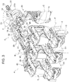
figure 3 shows a three-quarter front perspective view taken from the above of the main lighting module, with parts thereof cut away for sake of simplicity, and of all the secondary lighting modules of the lighting device offigure 1 arranged as they are mounted relative to each other inside the lighting device offigure 1 and of their operating and adjusting mechanisms; -
figure 4 shows in an enlarged scale a detail of one of the secondary lighting modules offigure 3 ; -
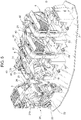
figure 5 shows a three-quarter rear perspective view taken from the above of all the lighting modules offigure 3 and of their operating and adjusting mechanisms, still with part of the main lighting module taken away; -
figure 6 shows in a further enlarges scale a three-quarter front perspective view taken from the above of the main lighting module viewed in its entirety and of an adjusting device thereof; and -
figure 7 shows a detail of an adjusting device of the secondary lighting modules. - With reference to
figure 1 , reference number 1 indicates as a whole a lighting device consisting, in the non-limiting embodiment shown, in a vehicle headlight assembly, which is only schematically shown from the front. - The lighting device 1 comprises a generally cup-
shaped housing body 2 designed to be mounted on a vehicle, known and not shown for sake of simplicity.Housing body 2 is made of synthetic plastic material by injection molding and has a front inlet opening 3 in use facing opposite to the vehicle and towards a forward driving direction FD of the vehicle, indicated by an arrow; thefront inlet opening 3 is closed by atransparent cover 4, normally constituted by a terse lens (i.e. a transparent lens not provided with optical functions). - According to one aspect of the present invention, the
housing body 2 carries at the interior thereof at least onemain lighting module 5 and at least two, and preferably three or more, in the embodiment shown three, secondary (or auxiliary)lighting modules main lighting module 5; all the modules 5-8 may be visible from the outside through thetransparent cover 4. - The
housing body 2 is designed to be mounted in a known manner on a vehicle (not shown) with the front inlet opening 3 arranged to face in use toward the forward driving direction FD of the vehicle; themain lighting module 5 and the at least two (three in the embodiment shown)secondary lighting modules housing body 2, facing the inlet opening. - The
main lighting module 5 is designed to be carried normally in a stationary manner within thehousing body 2. - The
secondary lighting modules housing body 2 rotatable in relation to thehousing body 2 itself and to themain lighting module 5, each around a respective its own first axis, each indicated infigures 1 and3 with a different reference letter "A", "B" and "C". - The first axes A,B,C of the
secondary lighting modules lighting devices figure 1 is shown the optical axis OA of thestationary lighting module 5 only, which is arranged parallel to the direction FD. The optical axes of thelighting modules - With reference to
figures 2 and4 , all the rotatinglighting module figure 2 it is shown shows for sake of simplicity thelighting module 6 only, but what described with reference tolighting module 6 also apply tolighting modules EP 3 176 493 A1 - Each lighting modules 6-8 therefore comprises a rigid, C-shaped
framed support 9 carrying in a rotatable manner around the respective first axis, namely around axis A infigure 2 , a rotatingoptical unit 10 comprising areflector 11 and alens 12 connected rigid together, facing each other. Theframed support 9 also bears at anupper end 13 thereof, defining the upper end of thewhole lighting module 6, a printedcircuit board 14 carrying in known manner at least one light source 15 (figure 7 ), and preferably a plurality of light sources, preferably all constituted by LEDs; theLED light source 15 and the eventual other LED light sources are known and not shown in details for sake of simplicity. - The
framed support 9 also caries at alower end 16 thereof, also constituting the lower end of each secondary lighting module 6-8, anactuator 17 constituted by an electric motor to rotate theoptical unit 10 of eachmodule respective light source 15 around the first axis of each module A, B, C. - According to one feature of the invention, the secondary lighting modules 6-8 and the
main lighting module 5 are constrained to thehousing body 2 so as to be rotatable in relation to thehousing body 2 around second axes arranged parallel to the horizontal plane. - The second axes of the secondary lighting modules 6-8 are indicated in
figure 3 with the reference letters "D", "E" and "F", for thelighting modules main lighting module 5 is indicated with the reference letter "G" and it is shown infigure 3 and, better, infigure 6 . - The rotation around the axes D-G has the object to correct in use the vertical position of the light beams generated by the lighting device 1 both in order to compensate the variations in loads of the vehicle and, as it will be seen, to automatically compensate for the asperity of the terrain in order to avoid to dazzle other incoming vehicles and to generate specific light distributions in order to improve the lighting performances of the lighting device 1.
- According to a first aspect of the invention, the secondary lighting modules 6-8 are mechanically connected together to form within the housing body 2 a
first sub-assembly 18 comprising the secondary lighting modules 6-8 and a first motorized actuator 19 (figures 3 and5 ) configured to rotate all the secondary lighting modules 6-8 together, i.e. simultaneously at the same time, around the respective second axes D-F. - In combination with the above, the
main lighting module 5 is configured to form within the housing body 2 a second sub-assembly comprising, other than thelighting module 5, a second motorizedactuator 21b configured to rotate themain lighting module 5 around its respective second axis G independently of thefirst motor actuator 19 and of thesecondary lighting modules - Moreover, according to a further feature of the invention, the first and
second sub-assembly operational element 21 arranged inside thehousing body 2 above and behind the lighting modules 5-8, so as to be axially movable in relation to thehousing body 2 under the thrust and action of a firstmanual adjusting device 22 provided within thehousing body 2. - The first
manual adjusting device 22 has afirst control element 23, in the embodiment shown an hexagonal gripping handle, crossing in a fluid tight manner (not shown for sake of simplicity) the rear wall of thehousing body 2 through a respectivefirst hole 24 thereof, to project outside thehousing body 2 opposite to theinlet opening 3. - The first
manual adjusting device 22 is configured to rotate of the same angle themain lighting module 5 and all the secondary lighting modules 6-8, the latter together, i.e. simultaneously, with thelighting module 5, around the second axes G and D-F thereof. - In the embodiment shown, the first and second motorized
actuators output shafts housing body 2 in a direction parallel to the optical axis OA of themain lighting module 5. - Moreover, each secondary lighting module 6-8 comprises (
figures 2 and4 ) afirst hinge 27 and asecond hinge 28, both provided integral with theframed support 9; thefirst hinge 27 is arranged at thelower end 16 of the secondary lighting module 6-8 and defines the respective second axis D-F; thesecond hinge 28 is arranged at theupper end 13 of each secondary lighting module 6-8, parallel to thefirst hinge 27. - According to the invention, the
first sub-assembly 18 also comprises adrag link rod 29 connecting the secondary lighting modules 6-8 to one another; thedrag link rod 29 is arranged within thehousing body 2 running above all the secondary lighting modules 6-8 and is connected, in the manner that will be described in details herein below, to thesecond hinge 28 of all the secondary lighting modules 6-8. - The
first sub-assembly 18 further comprises a secondmanual adjusting device 30 arranged within thehousing body 2 and having asecond control element 31 thereof (a star-shaped handle) facing thefront inlet opening 3. - The second
manual adjusting device 30 is configured to axially move the first motorizedactuator 19 relative to thehousing body 2 to make the secondary lighting modules 6-8 to rotate all together, i.e. simultaneously, around the respective second axes D-F relative to themain lighting module 5. - At this purpose, the first motorized
actuator 19 is carried by afirst support element 32 provided in a through manner with a threaded seat 33 (figure 3 ). - Moreover, the second
manual adjusting device 30 consists of the threadedseat 33 and of a threadedrod 34 engaging in a through manner the threadedseat 33. - The threaded
rod 34 has a first end constituted by thecontrol element 31, which is therefore carried integral to the first end of the threadedrod 34, angularly rigid therewith, and asecond end 35 mechanically linked to the commonoperational element 21 to which the first andsecond sub-assembly - In particular, the
second end 35 is linked to thecommon element 21 by means of aball joint 36. In this manner, the secondmanual adjusting device 30 is constrained by means of theball joint 36 to thecommon element 21 to which the first andsecond sub-assembly actuator 19 via therod 34,seat 33 andsupport element 32. - Accordingly, the second
manual adjusting device 30 connects, via theball joint 36 and thefirst support element 32, the first motorizedactuator 19 to thecommon element 21, as described above. - The
second sub-assembly 20 comprises a thirdmanual adjusting device 37 of generally known type and therefore not described in details for sake of simplicity; themanual adjusting device 37 is provided within thehousing body 2 and has athird control element 38, in the embodiment shown an hexagonal gripping handle, crossing in a fluid tight manner (not shown for sake of simplicity) the rear wall of thehousing body 2 through a respectivesecond hole 39 thereof, to project outside thehousing body 2 opposite to theinlet opening 3. - According to one feature of the invention, the third
manual adjusting device 37 is configured to rotate themain lighting module 5 around the second axis G thereof independently of the secondary lighting modules 6-8. - According to a further feature of the invention, the
drag link rod 29 is connected to thesecond hinge 28 of all the secondary lighting modules 6-8 via a respective fourthmanual adjusting device 40 for each lighting module 6-8. - Each
manual adjusting device 40 is configured to rotate the respective secondary module 6-8 around its respective second axis D-F relative to thedrag link rod 29, independently of the other secondary lighting modules 6-8. - Moreover, the
drag link rod 29 is connected axially rigid with thefirst motor actuator 19 to be moved thereby relative to thehousing body 2 and themain lighting module 5 via a connectingrod 41. The connectingrod 41 is arranged above thedrag link rod 29 and is connected thereto via ajoint 42. - Each fourth
manual adjusting device 40 comprises (figures 7 and4 ) apin 43 having a threadedfirst end 44 and asecond end 45 provided with a fork-shaped lug 46 rotationally linked to thesecond hinge 28 of the respective secondary lighting module 6-8. - Each adjusting
device 40 further comprises a cup-shaped throughseat 47 provided transversally within thedrag link rod 29 at thesecond hinge 28 of each secondary lighting module 6-8. Each cup-shaped throughseat 47 is engaged by thepin 43 on the side of thefirst end 44 thereof. Each adjustingdevice 40 also comprises aspiral spring 48 fitted onto thepin 43, on the side of thefirst end 44 thereof and arranged within the respective cup-shaped seat 47 of thedrag link rod 29, packed between a bottom wall of the cup-shaped through seat 47 (figure 7 ) and thesecond end 45 of thepin 43. - Finally, each adjusting
device 40 also comprises anut 50 screwed onto thefirst end 44 of thepin 43 and cooperating against thedrag link rod 29 on the side opposite to the respective cup-shaped throughseat 47 thereof to pull thepin 43 against the action of thespiral spring 48. - In this manner, each secondary lighting module 6-8 can be rotated around the respective axis D-F without moving the
drag link rod 29 and therefore independently of the other secondary lighting modules 6-8. - In order to let the sub-unit 18 to be pre-mounted before inserting it within the
housing body 2, the secondary lighting modules 6-8 are carried, either individually or all together, by a singlerigid base element 51 configured to receive all the lighting modules 6-8 or by a plurality of identicalrigid base elements 51 configured to receive one single secondary lighting module 6-8. - In both cases, each secondary lighting module 6-8 is hinged to the respective or
common base element 51 at the respective second axis D-F by means of thehinge 27. - In both cases, the respective or common
rigid base element 51 is configured to provide a support for thefirst sub-assembly 18 and to provide a mounting interface between thehousing body 2 and thefirst sub-assembly 18. - Owing to the described arrangements, it is possible to pre-assemble the sub-assembly 18 by linking each lighting module 6-8 to a
base element 51 and to thedrag link rod 29; after assembly, the angular position of each lighting module 6-8 relative to the respective second axis D-F is adjusted by means of thedevice 40, acting on the nuts 50. - Then the pre-assembly is completed by linking the drag link rod to the connecting
rod 41 and to theactuator 19, via the threadedrod 34 and thesupport element 32; finally the sub-assembly 18 is inserted within thehousing body 2 with the sub-assembly 20 already arranged therein and is connected to the common operational element by means of the ball joint 36. - At this point the angular position of all the lighting modules 6-8 relative to the
main lighting module 5 is adjusted by means ofdevice 30. Finally, the lighting device can be tested and the angular position of all the lighting modules 5-8 is adjusted by means ofdevice 22. - In the end, an extremely compact and effective arrangement is obtained which is easy to be assembled and above all, to be very finely tuned.
- All the aims of the invention are therefore accomplished.
Claims (9)
- A lighting device (1) for vehicles, comprising an housing body (2) designed to be mounted on a vehicle and having a front inlet opening (3) arranged to face in use toward a forward driving direction of the vehicle, a transparent cover (4) to close the front inlet opening, a main lighting module (5) and at least two secondary lighting modules (6,7,8), the main lighting module and the at least two secondary lighting modules being arranged inside the housing body (2), side by side, facing the inlet opening, the at least two secondary lighting modules (6,7,8) being carried within the housing body (2) rotatable in relation to the housing body and to the main lighting module, around respective first axes (A,B,C) arranged parallel to each other and transverse to an horizontal plane; and wherein the secondary lighting modules and the main lighting module are constrained to the housing body (2) so as to be rotatable in relation to the housing body around second axes (D,E,F,G) arranged parallel to the horizontal plane; wherein, in combination:i)- the secondary lighting modules (6-8) are mechanically connected together to form within the housing body a first sub-assembly (18) comprising a first motorized actuator (19) configured to rotate all the secondary lighting modules (6-8) together around the respective second axes;ii) the main lighting module (5) is configured to form within the housing body a second sub-assembly (20) comprising a second motorized actuator (21b) configured to rotate the main lighting module around its respective second axis independently of the first motor actuator (19) and of the secondary lighting modules (6-8); characterized in thatiii) the first and second sub-assembly (18,20) are mechanically connected to a common element (21) axially movable in relation to the housing body (2) under the thrust of a first manual adjusting device (22) provided within the housing body and having a first control element (23) passing through the housing body to project outside the housing body opposite to the inlet opening (3); the first adjusting device (22) being configured to rotate of the same angle the main and secondary lighting modules (5-8), all together, around the second axes (D-G) .
- A lighting device according to claim 1, characterized in that the first sub-assembly (18) comprises a second manual adjusting device (30) arranged within the housing body and having a second control element (31) thereof facing the front inlet opening (3), the second manual adjusting device being configured to axially move the first motorized actuator (19) relative to the housing body (2) to make the secondary lighting modules (6-8) to rotate all together around the respective second axes (D-F) relative to the main lighting module (5); the second manual adjusting device (30) being constrained by means of a ball joint (36) to the common element (21) to which the first and second sub-assembly (18,20) are both connected.
- A lighting device according to claim 2, characterized in that the second manual adjusting device (30) consists of a threaded rod (34) engaging a threaded seat (33) provided through a first support element (32) carrying the first motorized actuator (19); the threaded rod (34) having a first end carrying the second control element (31) angularly rigid thereto and a second (35) end linked to said common element (21) to which the first and second sub-assembly (18,20) are both connected via said ball joint (36), so as to connect to the common element (21) also the first motorized actuator (19) via said fist support element (32).
- A lighting device according to anyone of the preceding claims, characterized in that the second sub-assembly (20) comprises a third manual adjusting device (37) provided within the housing body and having a third control element (38) passing through the housing body to project outside the housing body (2) opposite to the inlet opening; the third manual adjusting device (37) being configured to rotate the main lighting module (5) around the second axis (G) thereof independently of the secondary lighting modules (6-8) .
- A lighting device according to anyone of the preceding claims, characterized in that each secondary lighting module (6-8) comprises a first and a second hinge (27,28); the first hinge (27) being arranged at a lower end (16) of the secondary lighting module and defining the respective second axis; and the second hinge (28) being arranged at a upper end (13) of the secondary lighting module, parallel to the first hinge (27); the first sub-assembly (18) further comprising a drag link rod (29) to connect together all the secondary lighting modules (6-8); the drag link rod (29) running above all the secondary lighting modules and being connected to the second hinge (28) of all the secondary lighting modules via a respective fourth manual adjusting device (40) configured to rotate the respective secondary module around its respective second axis relative to the drag link rod (29) and independently of the other secondary lighting devices; the drag link rod (29) being connected axially rigid with the first motor actuator (19) to be moved thereby relative to the housing body (2) and the main lighting module (5).
- A lighting device according to claim 5, characterized in that each fourth manual adjusting device (40) comprises: a pin (43) having a threaded first end (44) and a second end (45) provided with a lug (46) rotationally linked to the second hinge (28) of a respective secondary lighting module; a cup-shaped through seat (47) provided transversally within the drag link rod (29) at the second hinge (28) of each secondary lighting module (6-8), the cup-shaped through seat (47) being engaged by said pin (43) on the side of the first end (44) thereof; a spiral spring (48) fitted onto the pin, on the side of the first end thereof and arranged within the respective cup-shaped seat (47) of the drag link rod, packed between a bottom wall (49) of the cup-shaped through seat and the second end (45) of the pin; and a nut (50) screwed onto the first end of said pin and cooperating against the drag link rod (29) on the side opposite to the respective cup-shaped through seat (47) thereof to pull the pin (43) against the action of the spiral spring (48).
- A lighting device according to anyone of the preceding claims, characterized in that the secondary lighting modules (6-8) are carried, either individually or all together, by one or more rigid base element/s (51) to which each secondary lighting module is hinged at the respective second axis (D-F); the rigid base element/s (51) being configured to provide a support for the first sub-assembly (18) and to provide a mounting interface between the housing body (2) and the first sub-assembly (18).
- A lighting device according to anyone of the preceding claims, characterized in that said first and second motorized actuators (19,21b) consist of an electric motors having an output shaft (25,26) sliding axially relative to the housing body in a direction parallel to an optical axis (OA) of the main lighting module (5).
- Vehicle provided with a lighting device (1) according to anyone of the preceding claims.
Priority Applications (2)
| Application Number | Priority Date | Filing Date | Title |
|---|---|---|---|
| EP17185390.6A EP3441261B8 (en) | 2017-08-08 | 2017-08-08 | Lighting device for vehicles provided with rotating modules |
| CN201810896939.9A CN109386810B (en) | 2017-08-08 | 2018-08-08 | Lighting device for vehicle with rotating module |
Applications Claiming Priority (1)
| Application Number | Priority Date | Filing Date | Title |
|---|---|---|---|
| EP17185390.6A EP3441261B8 (en) | 2017-08-08 | 2017-08-08 | Lighting device for vehicles provided with rotating modules |
Publications (3)
| Publication Number | Publication Date |
|---|---|
| EP3441261A1 EP3441261A1 (en) | 2019-02-13 |
| EP3441261B1 true EP3441261B1 (en) | 2020-02-26 |
| EP3441261B8 EP3441261B8 (en) | 2020-04-08 |
Family
ID=59677003
Family Applications (1)
| Application Number | Title | Priority Date | Filing Date |
|---|---|---|---|
| EP17185390.6A Active EP3441261B8 (en) | 2017-08-08 | 2017-08-08 | Lighting device for vehicles provided with rotating modules |
Country Status (2)
| Country | Link |
|---|---|
| EP (1) | EP3441261B8 (en) |
| CN (1) | CN109386810B (en) |
Cited By (1)
| Publication number | Priority date | Publication date | Assignee | Title |
|---|---|---|---|---|
| US11788700B1 (en) | 2022-09-23 | 2023-10-17 | Eagle Eyes Traffic Industrial Co., Ltd. | Adjustable light fixture capable of preventing light holder from falling off |
Families Citing this family (5)
| Publication number | Priority date | Publication date | Assignee | Title |
|---|---|---|---|---|
| CN110220153B (en) * | 2018-03-02 | 2023-01-06 | 法雷奥照明湖北技术中心有限公司 | Adjusting device for a light emitting module, light emitting module and vehicle |
| FR3102827B1 (en) * | 2019-10-30 | 2022-11-04 | Psa Automobiles Sa | Trim correction device for a motor vehicle headlamp |
| WO2021209021A1 (en) * | 2020-04-17 | 2021-10-21 | 法雷奥市光(中国)车灯有限公司 | Light-emitting assembly, method for adjusting light-emitting assembly, and vehicle |
| EP4624254A1 (en) * | 2024-03-26 | 2025-10-01 | PO LIGHTING CZECH s.r.o. | Light unit of a vehicle headlamp module |
| CN119393694B (en) * | 2024-12-25 | 2025-06-06 | 佛山市指橙科技有限公司 | A vehicle light adjustment structure and vehicle light |
Family Cites Families (14)
| Publication number | Priority date | Publication date | Assignee | Title |
|---|---|---|---|---|
| KR20090063573A (en) * | 2007-12-14 | 2009-06-18 | 현대자동차주식회사 | LED Headlamp Aiming Device |
| CN201819166U (en) * | 2010-08-12 | 2011-05-04 | 杭州凹凸导光科技有限公司 | Connecting device |
| DE102011017538A1 (en) * | 2011-04-26 | 2012-10-31 | Automotive Lighting Reutlingen Gmbh | Adjusting unit for headlight mounted in vehicle, has adjusting element that includes rotary portion and carriage portion which are rotationally coupled to each other and are movably arranged in adjusting direction |
| AT514402B1 (en) * | 2013-05-16 | 2015-09-15 | Zizala Lichtsysteme Gmbh | vehicle headlights |
| CN203703833U (en) * | 2013-12-26 | 2014-07-09 | 北京申安投资集团有限公司 | Rotary scale assembly structure for regulating irradiation angle of LED (light emitting diode) lamp |
| FR3017189B1 (en) | 2014-02-04 | 2019-04-26 | Valeo Vision | ROTARY LIGHTING AND / OR SIGNALING MODULE WITH FIXED LIGHT SOURCE |
| US9587794B2 (en) * | 2014-05-21 | 2017-03-07 | Ford Global Technologies, Llc | Headlamp assembly with multiple high aspect ratio lenses |
| FR3022322B1 (en) | 2014-06-16 | 2016-07-15 | Valeo Vision | ROTARY LIGHTING AND / OR SIGNALING MODULE |
| FR3029266B1 (en) * | 2014-11-27 | 2020-08-07 | Peugeot Citroen Automobiles Sa | VEHICLE PROJECTOR |
| FR3039798B1 (en) * | 2015-08-06 | 2019-01-25 | Valeo Vision | DEVICE FOR LIGHTING AND / OR SIGNALING A MOTOR VEHICLE COMPRISING AT LEAST TWO LIGHTING MODULES. |
| US9809150B2 (en) * | 2015-10-28 | 2017-11-07 | GM Global Technology Operations LLC | Headlamp assembly |
| CN105387410A (en) * | 2015-11-24 | 2016-03-09 | 马瑞利汽车零部件(芜湖)有限公司 | AFS dimming module for automobile lamp |
| EP3176493B1 (en) * | 2015-11-24 | 2020-12-30 | Marelli Automotive Lighting Italy S.p.A. | Rotating lighting module and lighting device for vehicles |
| CN205498752U (en) * | 2016-03-30 | 2016-08-24 | 山东临工工程机械有限公司 | But height -adjusting warning light support |
-
2017
- 2017-08-08 EP EP17185390.6A patent/EP3441261B8/en active Active
-
2018
- 2018-08-08 CN CN201810896939.9A patent/CN109386810B/en active Active
Non-Patent Citations (1)
| Title |
|---|
| None * |
Cited By (1)
| Publication number | Priority date | Publication date | Assignee | Title |
|---|---|---|---|---|
| US11788700B1 (en) | 2022-09-23 | 2023-10-17 | Eagle Eyes Traffic Industrial Co., Ltd. | Adjustable light fixture capable of preventing light holder from falling off |
Also Published As
| Publication number | Publication date |
|---|---|
| EP3441261B8 (en) | 2020-04-08 |
| CN109386810A (en) | 2019-02-26 |
| CN109386810B (en) | 2022-02-18 |
| EP3441261A1 (en) | 2019-02-13 |
Similar Documents
| Publication | Publication Date | Title |
|---|---|---|
| EP3441261B1 (en) | Lighting device for vehicles provided with rotating modules | |
| US10272820B2 (en) | Synchronized lamp adjuster | |
| US9709235B2 (en) | Synchronized lamp adjuster | |
| US6799876B2 (en) | Lighting device with beam orientation adjustable support | |
| EP3176493B1 (en) | Rotating lighting module and lighting device for vehicles | |
| CN105416159B (en) | The regulating system of automobile front lamp | |
| US10267475B2 (en) | Light module and lighting device for a motor vehicle comprising such a light module | |
| CN105987336A (en) | Adjusting system for vehicle headlamp | |
| CN105318241B (en) | Rotary type illumination and/or signal designation module | |
| KR102199026B1 (en) | Setting device for a motor vehicle headlamp | |
| CN105209293B (en) | Headlamp equipped with retractable lighting module | |
| CN103373272B (en) | The illumination of adjusting apparatus including optimization and/or recoil simulator | |
| EP3650745B1 (en) | Lighting device for vehicles having light guides | |
| CN109519890A (en) | Car light ball nut and its installation and adjustment method, car headlamp | |
| RU2677540C2 (en) | Vehicle headlamp | |
| EP3354967B1 (en) | Rotating lighting module with welcome function and lighting device for vehicles | |
| ITMI990214A1 (en) | HEADLIGHT FOR HEADLIGHT AND HIGH BEAM FOR VEHICLES | |
| EP3354968B1 (en) | Lighting module and lighting device for vehicles having welcome function | |
| CN109099385B (en) | Lighting device for vehicle provided with rotary lighting module | |
| EP3431864B1 (en) | Lighting device for vehicles provided with rotating lighting modules | |
| CN109386806B (en) | Rotary lighting module for a vehicle and associated lighting device for a vehicle | |
| CN109578927B (en) | Lighting device with rotary module for vehicle | |
| JP5588237B2 (en) | Vehicle headlamp | |
| CN209079985U (en) | Unmanned vehicle steering mechanism and unmanned vehicle | |
| CN118998673B (en) | A lighting device for enhancing stage effects |
Legal Events
| Date | Code | Title | Description |
|---|---|---|---|
| PUAI | Public reference made under article 153(3) epc to a published international application that has entered the european phase |
Free format text: ORIGINAL CODE: 0009012 |
|
| STAA | Information on the status of an ep patent application or granted ep patent |
Free format text: STATUS: THE APPLICATION HAS BEEN PUBLISHED |
|
| AK | Designated contracting states |
Kind code of ref document: A1 Designated state(s): AL AT BE BG CH CY CZ DE DK EE ES FI FR GB GR HR HU IE IS IT LI LT LU LV MC MK MT NL NO PL PT RO RS SE SI SK SM TR |
|
| AX | Request for extension of the european patent |
Extension state: BA ME |
|
| STAA | Information on the status of an ep patent application or granted ep patent |
Free format text: STATUS: REQUEST FOR EXAMINATION WAS MADE |
|
| GRAP | Despatch of communication of intention to grant a patent |
Free format text: ORIGINAL CODE: EPIDOSNIGR1 |
|
| STAA | Information on the status of an ep patent application or granted ep patent |
Free format text: STATUS: GRANT OF PATENT IS INTENDED |
|
| 17P | Request for examination filed |
Effective date: 20190812 |
|
| RBV | Designated contracting states (corrected) |
Designated state(s): AL AT BE BG CH CY CZ DE DK EE ES FI FR GB GR HR HU IE IS IT LI LT LU LV MC MK MT NL NO PL PT RO RS SE SI SK SM TR |
|
| RIC1 | Information provided on ipc code assigned before grant |
Ipc: B60Q 1/068 20060101ALI20190830BHEP Ipc: B60Q 1/00 20060101AFI20190830BHEP Ipc: F21S 41/60 20180101ALI20190830BHEP Ipc: B60Q 1/076 20060101ALI20190830BHEP Ipc: F21S 41/675 20180101ALI20190830BHEP |
|
| INTG | Intention to grant announced |
Effective date: 20190918 |
|
| GRAS | Grant fee paid |
Free format text: ORIGINAL CODE: EPIDOSNIGR3 |
|
| GRAA | (expected) grant |
Free format text: ORIGINAL CODE: 0009210 |
|
| STAA | Information on the status of an ep patent application or granted ep patent |
Free format text: STATUS: THE PATENT HAS BEEN GRANTED |
|
| GRAM | Information related to correction after decision after decision to grant or to maintain patent in amended form deleted |
Free format text: ORIGINAL CODE: EPIDOSDCDEC |
|
| GRAT | Correction requested after decision to grant or after decision to maintain patent in amended form |
Free format text: ORIGINAL CODE: EPIDOSNCDEC |
|
| GRAT | Correction requested after decision to grant or after decision to maintain patent in amended form |
Free format text: ORIGINAL CODE: EPIDOSNCDEC |
|
| REG | Reference to a national code |
Ref country code: DE Ref legal event code: R081 Ref document number: 602017012167 Country of ref document: DE Owner name: PSA AUTOMOBILES SA, FR Free format text: FORMER OWNERS: AUTOMOTIVE LIGHTING ITALIA S.P.A., VENARIA REALE, TORINO, IT; PSA AUTOMOBILES SA, POISSY, FR Ref country code: DE Ref legal event code: R081 Ref document number: 602017012167 Country of ref document: DE Owner name: MAREILI AUTOMOTIVE LIGHTING ITALY S.P.A., VENA, IT Free format text: FORMER OWNERS: AUTOMOTIVE LIGHTING ITALIA S.P.A., VENARIA REALE, TORINO, IT; PSA AUTOMOBILES SA, POISSY, FR |
|
| AK | Designated contracting states |
Kind code of ref document: B1 Designated state(s): AL AT BE BG CH CY CZ DE DK EE ES FI FR GB GR HR HU IE IS IT LI LT LU LV MC MK MT NL NO PL PT RO RS SE SI SK SM TR |
|
| REG | Reference to a national code |
Ref country code: GB Ref legal event code: FG4D |
|
| REG | Reference to a national code |
Ref country code: CH Ref legal event code: EP |
|
| RAP2 | Party data changed (patent owner data changed or rights of a patent transferred) |
Owner name: MARELLI AUTOMOTIVE LIGHTING ITALY S.P.A. Owner name: PSA AUTOMOBILES SA |
|
| REG | Reference to a national code |
Ref country code: CH Ref legal event code: PK Free format text: BERICHTIGUNG B8 |
|
| REG | Reference to a national code |
Ref country code: AT Ref legal event code: REF Ref document number: 1237219 Country of ref document: AT Kind code of ref document: T Effective date: 20200315 |
|
| REG | Reference to a national code |
Ref country code: IE Ref legal event code: FG4D |
|
| REG | Reference to a national code |
Ref country code: DE Ref legal event code: R096 Ref document number: 602017012167 Country of ref document: DE |
|
| PG25 | Lapsed in a contracting state [announced via postgrant information from national office to epo] |
Ref country code: RS Free format text: LAPSE BECAUSE OF FAILURE TO SUBMIT A TRANSLATION OF THE DESCRIPTION OR TO PAY THE FEE WITHIN THE PRESCRIBED TIME-LIMIT Effective date: 20200226 Ref country code: NO Free format text: LAPSE BECAUSE OF FAILURE TO SUBMIT A TRANSLATION OF THE DESCRIPTION OR TO PAY THE FEE WITHIN THE PRESCRIBED TIME-LIMIT Effective date: 20200526 Ref country code: FI Free format text: LAPSE BECAUSE OF FAILURE TO SUBMIT A TRANSLATION OF THE DESCRIPTION OR TO PAY THE FEE WITHIN THE PRESCRIBED TIME-LIMIT Effective date: 20200226 |
|
| REG | Reference to a national code |
Ref country code: NL Ref legal event code: MP Effective date: 20200226 |
|
| REG | Reference to a national code |
Ref country code: LT Ref legal event code: MG4D |
|
| PG25 | Lapsed in a contracting state [announced via postgrant information from national office to epo] |
Ref country code: LV Free format text: LAPSE BECAUSE OF FAILURE TO SUBMIT A TRANSLATION OF THE DESCRIPTION OR TO PAY THE FEE WITHIN THE PRESCRIBED TIME-LIMIT Effective date: 20200226 Ref country code: HR Free format text: LAPSE BECAUSE OF FAILURE TO SUBMIT A TRANSLATION OF THE DESCRIPTION OR TO PAY THE FEE WITHIN THE PRESCRIBED TIME-LIMIT Effective date: 20200226 Ref country code: GR Free format text: LAPSE BECAUSE OF FAILURE TO SUBMIT A TRANSLATION OF THE DESCRIPTION OR TO PAY THE FEE WITHIN THE PRESCRIBED TIME-LIMIT Effective date: 20200527 Ref country code: IS Free format text: LAPSE BECAUSE OF FAILURE TO SUBMIT A TRANSLATION OF THE DESCRIPTION OR TO PAY THE FEE WITHIN THE PRESCRIBED TIME-LIMIT Effective date: 20200626 Ref country code: SE Free format text: LAPSE BECAUSE OF FAILURE TO SUBMIT A TRANSLATION OF THE DESCRIPTION OR TO PAY THE FEE WITHIN THE PRESCRIBED TIME-LIMIT Effective date: 20200226 Ref country code: BG Free format text: LAPSE BECAUSE OF FAILURE TO SUBMIT A TRANSLATION OF THE DESCRIPTION OR TO PAY THE FEE WITHIN THE PRESCRIBED TIME-LIMIT Effective date: 20200526 |
|
| PG25 | Lapsed in a contracting state [announced via postgrant information from national office to epo] |
Ref country code: NL Free format text: LAPSE BECAUSE OF FAILURE TO SUBMIT A TRANSLATION OF THE DESCRIPTION OR TO PAY THE FEE WITHIN THE PRESCRIBED TIME-LIMIT Effective date: 20200226 |
|
| PG25 | Lapsed in a contracting state [announced via postgrant information from national office to epo] |
Ref country code: SK Free format text: LAPSE BECAUSE OF FAILURE TO SUBMIT A TRANSLATION OF THE DESCRIPTION OR TO PAY THE FEE WITHIN THE PRESCRIBED TIME-LIMIT Effective date: 20200226 Ref country code: CZ Free format text: LAPSE BECAUSE OF FAILURE TO SUBMIT A TRANSLATION OF THE DESCRIPTION OR TO PAY THE FEE WITHIN THE PRESCRIBED TIME-LIMIT Effective date: 20200226 Ref country code: RO Free format text: LAPSE BECAUSE OF FAILURE TO SUBMIT A TRANSLATION OF THE DESCRIPTION OR TO PAY THE FEE WITHIN THE PRESCRIBED TIME-LIMIT Effective date: 20200226 Ref country code: LT Free format text: LAPSE BECAUSE OF FAILURE TO SUBMIT A TRANSLATION OF THE DESCRIPTION OR TO PAY THE FEE WITHIN THE PRESCRIBED TIME-LIMIT Effective date: 20200226 Ref country code: ES Free format text: LAPSE BECAUSE OF FAILURE TO SUBMIT A TRANSLATION OF THE DESCRIPTION OR TO PAY THE FEE WITHIN THE PRESCRIBED TIME-LIMIT Effective date: 20200226 Ref country code: PT Free format text: LAPSE BECAUSE OF FAILURE TO SUBMIT A TRANSLATION OF THE DESCRIPTION OR TO PAY THE FEE WITHIN THE PRESCRIBED TIME-LIMIT Effective date: 20200719 Ref country code: EE Free format text: LAPSE BECAUSE OF FAILURE TO SUBMIT A TRANSLATION OF THE DESCRIPTION OR TO PAY THE FEE WITHIN THE PRESCRIBED TIME-LIMIT Effective date: 20200226 Ref country code: DK Free format text: LAPSE BECAUSE OF FAILURE TO SUBMIT A TRANSLATION OF THE DESCRIPTION OR TO PAY THE FEE WITHIN THE PRESCRIBED TIME-LIMIT Effective date: 20200226 Ref country code: SM Free format text: LAPSE BECAUSE OF FAILURE TO SUBMIT A TRANSLATION OF THE DESCRIPTION OR TO PAY THE FEE WITHIN THE PRESCRIBED TIME-LIMIT Effective date: 20200226 |
|
| RAP2 | Party data changed (patent owner data changed or rights of a patent transferred) |
Owner name: MARELLI AUTOMOTIVE LIGHTING ITALY S.P.A. Owner name: PSA AUTOMOBILES SA |
|
| REG | Reference to a national code |
Ref country code: AT Ref legal event code: MK05 Ref document number: 1237219 Country of ref document: AT Kind code of ref document: T Effective date: 20200226 |
|
| REG | Reference to a national code |
Ref country code: DE Ref legal event code: R097 Ref document number: 602017012167 Country of ref document: DE |
|
| PLBE | No opposition filed within time limit |
Free format text: ORIGINAL CODE: 0009261 |
|
| STAA | Information on the status of an ep patent application or granted ep patent |
Free format text: STATUS: NO OPPOSITION FILED WITHIN TIME LIMIT |
|
| PG25 | Lapsed in a contracting state [announced via postgrant information from national office to epo] |
Ref country code: AT Free format text: LAPSE BECAUSE OF FAILURE TO SUBMIT A TRANSLATION OF THE DESCRIPTION OR TO PAY THE FEE WITHIN THE PRESCRIBED TIME-LIMIT Effective date: 20200226 |
|
| 26N | No opposition filed |
Effective date: 20201127 |
|
| PG25 | Lapsed in a contracting state [announced via postgrant information from national office to epo] |
Ref country code: SI Free format text: LAPSE BECAUSE OF FAILURE TO SUBMIT A TRANSLATION OF THE DESCRIPTION OR TO PAY THE FEE WITHIN THE PRESCRIBED TIME-LIMIT Effective date: 20200226 Ref country code: PL Free format text: LAPSE BECAUSE OF FAILURE TO SUBMIT A TRANSLATION OF THE DESCRIPTION OR TO PAY THE FEE WITHIN THE PRESCRIBED TIME-LIMIT Effective date: 20200226 |
|
| PG25 | Lapsed in a contracting state [announced via postgrant information from national office to epo] |
Ref country code: MC Free format text: LAPSE BECAUSE OF FAILURE TO SUBMIT A TRANSLATION OF THE DESCRIPTION OR TO PAY THE FEE WITHIN THE PRESCRIBED TIME-LIMIT Effective date: 20200226 |
|
| REG | Reference to a national code |
Ref country code: CH Ref legal event code: PL |
|
| PG25 | Lapsed in a contracting state [announced via postgrant information from national office to epo] |
Ref country code: CH Free format text: LAPSE BECAUSE OF NON-PAYMENT OF DUE FEES Effective date: 20200831 Ref country code: LU Free format text: LAPSE BECAUSE OF NON-PAYMENT OF DUE FEES Effective date: 20200808 Ref country code: LI Free format text: LAPSE BECAUSE OF NON-PAYMENT OF DUE FEES Effective date: 20200831 |
|
| REG | Reference to a national code |
Ref country code: BE Ref legal event code: MM Effective date: 20200831 |
|
| PG25 | Lapsed in a contracting state [announced via postgrant information from national office to epo] |
Ref country code: BE Free format text: LAPSE BECAUSE OF NON-PAYMENT OF DUE FEES Effective date: 20200831 Ref country code: IE Free format text: LAPSE BECAUSE OF NON-PAYMENT OF DUE FEES Effective date: 20200808 |
|
| GBPC | Gb: european patent ceased through non-payment of renewal fee |
Effective date: 20210808 |
|
| PG25 | Lapsed in a contracting state [announced via postgrant information from national office to epo] |
Ref country code: MT Free format text: LAPSE BECAUSE OF FAILURE TO SUBMIT A TRANSLATION OF THE DESCRIPTION OR TO PAY THE FEE WITHIN THE PRESCRIBED TIME-LIMIT Effective date: 20200226 Ref country code: CY Free format text: LAPSE BECAUSE OF FAILURE TO SUBMIT A TRANSLATION OF THE DESCRIPTION OR TO PAY THE FEE WITHIN THE PRESCRIBED TIME-LIMIT Effective date: 20200226 |
|
| PG25 | Lapsed in a contracting state [announced via postgrant information from national office to epo] |
Ref country code: MK Free format text: LAPSE BECAUSE OF FAILURE TO SUBMIT A TRANSLATION OF THE DESCRIPTION OR TO PAY THE FEE WITHIN THE PRESCRIBED TIME-LIMIT Effective date: 20200226 Ref country code: AL Free format text: LAPSE BECAUSE OF FAILURE TO SUBMIT A TRANSLATION OF THE DESCRIPTION OR TO PAY THE FEE WITHIN THE PRESCRIBED TIME-LIMIT Effective date: 20200226 |
|
| PG25 | Lapsed in a contracting state [announced via postgrant information from national office to epo] |
Ref country code: GB Free format text: LAPSE BECAUSE OF NON-PAYMENT OF DUE FEES Effective date: 20210808 |
|
| PGFP | Annual fee paid to national office [announced via postgrant information from national office to epo] |
Ref country code: DE Payment date: 20250724 Year of fee payment: 9 |
|
| PGFP | Annual fee paid to national office [announced via postgrant information from national office to epo] |
Ref country code: TR Payment date: 20250731 Year of fee payment: 9 Ref country code: IT Payment date: 20250723 Year of fee payment: 9 |
|
| PGFP | Annual fee paid to national office [announced via postgrant information from national office to epo] |
Ref country code: FR Payment date: 20250723 Year of fee payment: 9 |