EP3441260A1 - Loading and unloading system for hazardous goods tankers - Google Patents
Loading and unloading system for hazardous goods tankers Download PDFInfo
- Publication number
- EP3441260A1 EP3441260A1 EP17382557.1A EP17382557A EP3441260A1 EP 3441260 A1 EP3441260 A1 EP 3441260A1 EP 17382557 A EP17382557 A EP 17382557A EP 3441260 A1 EP3441260 A1 EP 3441260A1
- Authority
- EP
- European Patent Office
- Prior art keywords
- tanker
- loading
- valve
- manhole
- actuator
- Prior art date
- Legal status (The legal status is an assumption and is not a legal conclusion. Google has not performed a legal analysis and makes no representation as to the accuracy of the status listed.)
- Granted
Links
Images
Classifications
-
- B—PERFORMING OPERATIONS; TRANSPORTING
- B60—VEHICLES IN GENERAL
- B60P—VEHICLES ADAPTED FOR LOAD TRANSPORTATION OR TO TRANSPORT, TO CARRY, OR TO COMPRISE SPECIAL LOADS OR OBJECTS
- B60P3/00—Vehicles adapted to transport, to carry or to comprise special loads or objects
- B60P3/22—Tank vehicles
- B60P3/224—Tank vehicles comprising auxiliary devices, e.g. for unloading or level indicating
- B60P3/226—Arrangements of access openings or covers therefor
Definitions
- the object of the present invention is a system for loading and unloading tanker trucks carrying dangerous goods that does not require access to the top of the tankers.
- This system is of particular value in top-loading operations, that is to say, when loading is performed through the top of the tanker, as the system enables the operation to be performed without requiring personnel to access the top of the tanker; likewise access to the top is not required either in the unloading operation.
- the present invention is characterised by the special configuration and functionality of the elements used which enable a loading and unloading system offering a high degree of safety and protection for operators during loading and unloading work by eliminating the need for personnel to access the top of the vehicles.
- This invention therefore falls within the area of tanker trucks on the one hand, and of opening and closing methods for supplying liquid on the other.
- manholes also known as loading hatches.
- the tanker accesses the loading facilities in factories or loading tanks and is positioned under what is known as the loading arm. The operator must then access the top of the tanker to open the manhole in order to allow the loading arm to be inserted and the tanker filled. This manhole is also used to gain access to the interior of the tanker for repair and maintenance work.
- This loading and unloading system requires a system for accessing the top of the tanker, located at a height of over 3 metres, with the corresponding protection systems for work at height, and the subsequent risk assessment in order to draw up working procedures and safety equipment for the working platforms of the tankers, said equipment generally comprising an access ladder, work platforms and protective railings.
- the manhole must be opened and later closed manually, sometimes in high temperature conditions (due to the product transported) with fumes being emitted from the goods being loaded. This procedure entails the possibility of human error if the right tightening torque is not applied to close the manhole securely, with a subsequent possibility of accident as a result of leakage of the product and escape of fumes.
- the object of the present invention is therefore to avoid the possible accidents and risks involved in loading and unloading of goods tankers as performed heretofore, by developing a loading and unloading system such as that described below, whose essential details are set out in Claim 1.
- the object of the present invention is a system for loading tankers carrying dangerous goods to replace the manhole or loading hatch with a remotely controlled guillotine, knife-gate or slide-gate valve, adapted to the manhole of the tanker.
- the diameter of said valve is adapted to the dimensions of the hoses of the loading pipes, which can range from 100 to 700 mm in diameter.
- the valve has remote actuator systems which may be pneumatic, hydraulic, electrical, by radiofrequency or mechanical, such that they cause the valve to open or close, by moving the knife-gate, guillotine or slide-gate in the valve.
- the valve is fully opening, thus allowing the loading pipe or hose to be inserted without impediment, and allowing the filling operation to be carried out with no modification to current systems at loading facilities.
- the loading system of the tanker is thus entirely autonomous and independent of the loading system and is therefore valid for all present systems.
- valve is remotely closed, without requiring access to the top of the tanker, with the subsequent advantage in terms of safety, as well as ensuring that the valve is tightly closed, since it has been closed automatically using devices that are not manually operated directly on the valve.
- valve When it is necessary to unload or empty the tanker, once the unloading hose has been connected, the valve is remotely opened, with the subsequent advantage in terms of safety derived from the fact that it is not necessary to work at height or in immediate proximity to the goods, as well as ensuring correct opening by performing the operation automatically, without requiring physical intervention by personnel.
- the valve In the case of unloading of the goods using high-pressure air, the valve may remain closed, working at the design pressure, without loss of sealing or pressure, and the operator is never required to be in close proximity to the goods.
- Figure 1 shows a tank or tanker (1) fitted with a manhole (2) containing a filler neck (3) protruding perpendicularly to the surface of the tank, with a cover flange (4) to close the tank (1) on the free edge of the neck (3).
- shut-off valve (5) preferably fully-closing, containing a remotely-controlled actuator (6), as well as closing devices, which in the embodiment shown here are a knife-gate, guillotine or slide-gate (7).
- the shut-off valve (5) is secured on the manhole (2) of the tanker (1) in a preferred embodiment by means of a fixing flange (8) which ensures that the valve is secured on the cover flange (4) of the tanker (1).
- the actuator (2) may be an electrical, mechanical, hydraulic, pneumatic or any other possible type of valve actuator, while the remote-controlled actuator devices will be any of those already known, such as manual, electric, hydraulic, pneumatic or by means of radiofrequency.
Landscapes
- Engineering & Computer Science (AREA)
- Health & Medical Sciences (AREA)
- Public Health (AREA)
- Transportation (AREA)
- Mechanical Engineering (AREA)
- Loading And Unloading Of Fuel Tanks Or Ships (AREA)
- Ship Loading And Unloading (AREA)
- Air Transport Of Granular Materials (AREA)
Abstract
Description
- The object of the present invention, as established in the title of the invention, is a system for loading and unloading tanker trucks carrying dangerous goods that does not require access to the top of the tankers. This system is of particular value in top-loading operations, that is to say, when loading is performed through the top of the tanker, as the system enables the operation to be performed without requiring personnel to access the top of the tanker; likewise access to the top is not required either in the unloading operation.
- The present invention is characterised by the special configuration and functionality of the elements used which enable a loading and unloading system offering a high degree of safety and protection for operators during loading and unloading work by eliminating the need for personnel to access the top of the vehicles.
- This invention therefore falls within the area of tanker trucks on the one hand, and of opening and closing methods for supplying liquid on the other.
- Traditionally the system for loading tanker trucks carrying bulk dangerous goods is performed through the top of the vehicle by way of what are called manholes, also known as loading hatches.
- To perform loading and unloading, the tanker accesses the loading facilities in factories or loading tanks and is positioned under what is known as the loading arm. The operator must then access the top of the tanker to open the manhole in order to allow the loading arm to be inserted and the tanker filled. This manhole is also used to gain access to the interior of the tanker for repair and maintenance work.
- This loading and unloading system requires a system for accessing the top of the tanker, located at a height of over 3 metres, with the corresponding protection systems for work at height, and the subsequent risk assessment in order to draw up working procedures and safety equipment for the working platforms of the tankers, said equipment generally comprising an access ladder, work platforms and protective railings.
- The manhole must be opened and later closed manually, sometimes in high temperature conditions (due to the product transported) with fumes being emitted from the goods being loaded. This procedure entails the possibility of human error if the right tightening torque is not applied to close the manhole securely, with a subsequent possibility of accident as a result of leakage of the product and escape of fumes.
- Several accidents have been reported with subsequent loss of human life due to the possibility of human error. In one case, for example, the bolts of the manhole on a tanker loaded with asphalt were not properly closed, resulting in a leakage which caused the death of the driver.
- The current procedure for unloading top-loading tankers also requires that personnel from the unloading facilities or the drivers themselves access the top of the tanker to open the manhole before unloading and to close the manhole after unloading, with the same safety problems for work at height as mentioned above, frequently in the open air and in unfavourable conditions.
- The object of the present invention is therefore to avoid the possible accidents and risks involved in loading and unloading of goods tankers as performed heretofore, by developing a loading and unloading system such as that described below, whose essential details are set out in Claim 1.
- The object of the present invention is a system for loading tankers carrying dangerous goods to replace the manhole or loading hatch with a remotely controlled guillotine, knife-gate or slide-gate valve, adapted to the manhole of the tanker.
- The diameter of said valve is adapted to the dimensions of the hoses of the loading pipes, which can range from 100 to 700 mm in diameter.
- The valve has remote actuator systems which may be pneumatic, hydraulic, electrical, by radiofrequency or mechanical, such that they cause the valve to open or close, by moving the knife-gate, guillotine or slide-gate in the valve.
- The valve is fully opening, thus allowing the loading pipe or hose to be inserted without impediment, and allowing the filling operation to be carried out with no modification to current systems at loading facilities. The loading system of the tanker is thus entirely autonomous and independent of the loading system and is therefore valid for all present systems.
- Once loading of the tanker has concluded, the valve is remotely closed, without requiring access to the top of the tanker, with the subsequent advantage in terms of safety, as well as ensuring that the valve is tightly closed, since it has been closed automatically using devices that are not manually operated directly on the valve.
- When it is necessary to unload or empty the tanker, once the unloading hose has been connected, the valve is remotely opened, with the subsequent advantage in terms of safety derived from the fact that it is not necessary to work at height or in immediate proximity to the goods, as well as ensuring correct opening by performing the operation automatically, without requiring physical intervention by personnel.
- In the case of unloading of the goods using high-pressure air, the valve may remain closed, working at the design pressure, without loss of sealing or pressure, and the operator is never required to be in close proximity to the goods.
- Unless otherwise specified, all technical and scientific elements used in this specification have the meaning habitually understood by a person skilled in the art to which this invention pertains. In the practice of the present invention, similar or equivalent procedures and materials to those described in the specification may be used.
- Throughout the description and the claims, the word "contains", "comprises" and any variations thereon shall not be intended to exclude other technical characteristics, additives, components or steps. For experts in the field, other objects, advantages and characteristics of the invention will emerge partly from the description and partly from practice with the invention.
- To complete the description made herein and in order better to aid understanding of the characteristics of the invention, according to a preferential example of a practical embodiment thereof, this description is accompanied by a set of drawings showing as follows in indicative, but not limitative terms.
-
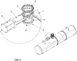
Figure 1 shows a detailed perspective aerial view of the tanker loading system that forms the object of the invention. -
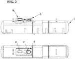
Figure 2 shows a side view of the system represented above. - According to the figures one preferred embodiment of the proposed invention is described below.
-
Figure 1 shows a tank or tanker (1) fitted with a manhole (2) containing a filler neck (3) protruding perpendicularly to the surface of the tank, with a cover flange (4) to close the tank (1) on the free edge of the neck (3). - In addition, over the manhole of the tank is fitted a shut-off valve (5), preferably fully-closing, containing a remotely-controlled actuator (6), as well as closing devices, which in the embodiment shown here are a knife-gate, guillotine or slide-gate (7).
- The shut-off valve (5) is secured on the manhole (2) of the tanker (1) in a preferred embodiment by means of a fixing flange (8) which ensures that the valve is secured on the cover flange (4) of the tanker (1).
- The actuator (2) may be an electrical, mechanical, hydraulic, pneumatic or any other possible type of valve actuator, while the remote-controlled actuator devices will be any of those already known, such as manual, electric, hydraulic, pneumatic or by means of radiofrequency.
- The characteristics described above achieve above all the safety of the operators, since they do not have to perform loading and unloading work at height or in the proximity of the goods, and also of the goods themselves by ensuring secure opening and closing since this is performed with automatic devices and not by way of manual manoeuvres which are always prone to possible error.
- Having sufficiently described the nature of the present invention, and the means of implementing it, it is noted that within the same essence, it may be made in other embodiments differing in detail from that indicated herein as an example, and to which the protection obtained shall equally extend, provided that it does not alter, change or modify its basic principle.
Claims (3)
- Loading and unloading system for tanker trucks carrying dangerous goods comprising a tanker (1) fitted with a manhole (2) containing a neck (3) which protrudes perpendicularly to the surface of the tank with a cover flange (4) on the free edge of the neck (3) to close the tanker (1) characterised by the fact that secured on the manhole (2) of the tank there is a shut-off valve (5) containing an actuator (6) remotely controlled by means of actuator devices, where the shut-off valve (5) has a knife-gate, guillotine or slide-gate (7).
- Loading and unloading system for tanker trucks carrying dangerous goods according to Claim 1 characterised by the fact that the actuator (6) is an electrical, mechanical, hydraulic or pneumatic actuator, while the remote-control device is manual, electrical, hydraulic, pneumatic or by means of radiofrequency.
- Loading and unloading system for tanker trucks carrying dangerous goods according to Claim 1 or 2 characterised by the fact that the shut-off valve (5) is secured on the manhole (2) of the tanker (1) by means of a fixing flange (8) which ensures proper securing of the valve on the cover flange (4) of the tanker (1).
Priority Applications (3)
| Application Number | Priority Date | Filing Date | Title |
|---|---|---|---|
| PT173825571T PT3441260T (en) | 2017-08-07 | 2017-08-07 | Loading and unloading system for hazardous goods tankers |
| ES17382557T ES2800678T3 (en) | 2017-08-07 | 2017-08-07 | Dangerous goods tank loading and unloading system |
| EP17382557.1A EP3441260B1 (en) | 2017-08-07 | 2017-08-07 | Loading and unloading system for hazardous goods tankers |
Applications Claiming Priority (1)
| Application Number | Priority Date | Filing Date | Title |
|---|---|---|---|
| EP17382557.1A EP3441260B1 (en) | 2017-08-07 | 2017-08-07 | Loading and unloading system for hazardous goods tankers |
Publications (2)
| Publication Number | Publication Date |
|---|---|
| EP3441260A1 true EP3441260A1 (en) | 2019-02-13 |
| EP3441260B1 EP3441260B1 (en) | 2020-03-04 |
Family
ID=59772581
Family Applications (1)
| Application Number | Title | Priority Date | Filing Date |
|---|---|---|---|
| EP17382557.1A Active EP3441260B1 (en) | 2017-08-07 | 2017-08-07 | Loading and unloading system for hazardous goods tankers |
Country Status (3)
| Country | Link |
|---|---|
| EP (1) | EP3441260B1 (en) |
| ES (1) | ES2800678T3 (en) |
| PT (1) | PT3441260T (en) |
Cited By (3)
| Publication number | Priority date | Publication date | Assignee | Title |
|---|---|---|---|---|
| US11814506B2 (en) | 2019-07-02 | 2023-11-14 | Marathon Petroleum Company Lp | Modified asphalts with enhanced rheological properties and associated methods |
| US12304377B2 (en) | 2020-05-21 | 2025-05-20 | Marathon Petroleum Company Lp | Systems and methods for venting tanks to enhance transporting asphalt |
| USRE50456E1 (en) | 2016-05-26 | 2025-06-10 | Marathon Petroleum Company Lp | Method of making an asphalt composition containing ester bottoms |
Citations (3)
| Publication number | Priority date | Publication date | Assignee | Title |
|---|---|---|---|---|
| US3142410A (en) * | 1962-10-03 | 1964-07-28 | Ethyl Corp | Sliding closure and operating means |
| US6318402B1 (en) * | 2000-05-25 | 2001-11-20 | Richard Ladeira | Pneumatic tank truck closure apparatus |
| US20140090300A1 (en) * | 2012-10-02 | 2014-04-03 | Mark Hoffmann | Door actuator assembly and method |
-
2017
- 2017-08-07 PT PT173825571T patent/PT3441260T/en unknown
- 2017-08-07 ES ES17382557T patent/ES2800678T3/en active Active
- 2017-08-07 EP EP17382557.1A patent/EP3441260B1/en active Active
Patent Citations (3)
| Publication number | Priority date | Publication date | Assignee | Title |
|---|---|---|---|---|
| US3142410A (en) * | 1962-10-03 | 1964-07-28 | Ethyl Corp | Sliding closure and operating means |
| US6318402B1 (en) * | 2000-05-25 | 2001-11-20 | Richard Ladeira | Pneumatic tank truck closure apparatus |
| US20140090300A1 (en) * | 2012-10-02 | 2014-04-03 | Mark Hoffmann | Door actuator assembly and method |
Cited By (3)
| Publication number | Priority date | Publication date | Assignee | Title |
|---|---|---|---|---|
| USRE50456E1 (en) | 2016-05-26 | 2025-06-10 | Marathon Petroleum Company Lp | Method of making an asphalt composition containing ester bottoms |
| US11814506B2 (en) | 2019-07-02 | 2023-11-14 | Marathon Petroleum Company Lp | Modified asphalts with enhanced rheological properties and associated methods |
| US12304377B2 (en) | 2020-05-21 | 2025-05-20 | Marathon Petroleum Company Lp | Systems and methods for venting tanks to enhance transporting asphalt |
Also Published As
| Publication number | Publication date |
|---|---|
| PT3441260T (en) | 2020-06-16 |
| ES2800678T3 (en) | 2021-01-04 |
| EP3441260B1 (en) | 2020-03-04 |
Similar Documents
| Publication | Publication Date | Title |
|---|---|---|
| EP3441260B1 (en) | Loading and unloading system for hazardous goods tankers | |
| US20220364655A1 (en) | Valve Cover | |
| CA2959888C (en) | Cargo tank assemblies with ground level access | |
| US3908718A (en) | Vapour recovery systems of liquid fuel storage | |
| US20230166146A1 (en) | Method and apparatus for launching and recovering a remote inspection device | |
| US2803269A (en) | Liquid dispensing and vapor recovery system | |
| US4310012A (en) | Thermal and remote valve control | |
| US3310070A (en) | Selective valve actuating mechanism for vessels | |
| MXPA03009437A (en) | Security device and method to prevent unauthorized discharge of contents from a tank. | |
| US9739390B2 (en) | Valve pressure assembly and methods of operating the same | |
| US4121614A (en) | Valve guard for bottom operated tank car valve | |
| US20170335986A1 (en) | Storage Tank Valve | |
| US5170819A (en) | Valve system for mobile tank cars | |
| CN215097555U (en) | Top adding and discharging system of liquefied gas railway pressure tank car and pressure tank car | |
| US20180162279A1 (en) | Walkway and safety rail apparatus. | |
| CA2919610C (en) | Valve cover | |
| US4114636A (en) | Bottom operable air inlet and outlet valve | |
| CN210440968U (en) | Pipeline structure and liquefied gas storage and transportation equipment with same | |
| EP3803162B1 (en) | Vessel closure device with fail safe failure detection means | |
| US5170988A (en) | Internal tank valve | |
| CN112319526A (en) | A liquefied gas railway pressure tank car top adding and discharging system and pressure tank car | |
| US4137937A (en) | Adapter for bottom operable tank car valve | |
| US3840056A (en) | Apparatus for filling liquid storage tanks | |
| CA2865992C (en) | Closure for fluid ports in a production tank | |
| BE1029681A1 (en) | Method for inspecting a tank, lock device and arrangement, comprising a tank, a lock device and an inspection device |
Legal Events
| Date | Code | Title | Description |
|---|---|---|---|
| PUAI | Public reference made under article 153(3) epc to a published international application that has entered the european phase |
Free format text: ORIGINAL CODE: 0009012 |
|
| STAA | Information on the status of an ep patent application or granted ep patent |
Free format text: STATUS: THE APPLICATION HAS BEEN PUBLISHED |
|
| AK | Designated contracting states |
Kind code of ref document: A1 Designated state(s): AL AT BE BG CH CY CZ DE DK EE ES FI FR GB GR HR HU IE IS IT LI LT LU LV MC MK MT NL NO PL PT RO RS SE SI SK SM TR |
|
| AX | Request for extension of the european patent |
Extension state: BA ME |
|
| STAA | Information on the status of an ep patent application or granted ep patent |
Free format text: STATUS: REQUEST FOR EXAMINATION WAS MADE |
|
| 17P | Request for examination filed |
Effective date: 20190227 |
|
| RBV | Designated contracting states (corrected) |
Designated state(s): AL AT BE BG CH CY CZ DE DK EE ES FI FR GB GR HR HU IE IS IT LI LT LU LV MC MK MT NL NO PL PT RO RS SE SI SK SM TR |
|
| GRAP | Despatch of communication of intention to grant a patent |
Free format text: ORIGINAL CODE: EPIDOSNIGR1 |
|
| STAA | Information on the status of an ep patent application or granted ep patent |
Free format text: STATUS: GRANT OF PATENT IS INTENDED |
|
| RIC1 | Information provided on ipc code assigned before grant |
Ipc: B60P 3/00 20060101AFI20190918BHEP Ipc: B60P 3/22 20060101ALN20190918BHEP |
|
| INTG | Intention to grant announced |
Effective date: 20191007 |
|
| GRAS | Grant fee paid |
Free format text: ORIGINAL CODE: EPIDOSNIGR3 |
|
| GRAA | (expected) grant |
Free format text: ORIGINAL CODE: 0009210 |
|
| STAA | Information on the status of an ep patent application or granted ep patent |
Free format text: STATUS: THE PATENT HAS BEEN GRANTED |
|
| AK | Designated contracting states |
Kind code of ref document: B1 Designated state(s): AL AT BE BG CH CY CZ DE DK EE ES FI FR GB GR HR HU IE IS IT LI LT LU LV MC MK MT NL NO PL PT RO RS SE SI SK SM TR |
|
| REG | Reference to a national code |
Ref country code: GB Ref legal event code: FG4D |
|
| REG | Reference to a national code |
Ref country code: CH Ref legal event code: EP |
|
| REG | Reference to a national code |
Ref country code: AT Ref legal event code: REF Ref document number: 1239998 Country of ref document: AT Kind code of ref document: T Effective date: 20200315 |
|
| REG | Reference to a national code |
Ref country code: DE Ref legal event code: R096 Ref document number: 602017012547 Country of ref document: DE |
|
| REG | Reference to a national code |
Ref country code: IE Ref legal event code: FG4D |
|
| REG | Reference to a national code |
Ref country code: PT Ref legal event code: SC4A Ref document number: 3441260 Country of ref document: PT Date of ref document: 20200616 Kind code of ref document: T Free format text: AVAILABILITY OF NATIONAL TRANSLATION Effective date: 20200601 |
|
| PG25 | Lapsed in a contracting state [announced via postgrant information from national office to epo] |
Ref country code: FI Free format text: LAPSE BECAUSE OF FAILURE TO SUBMIT A TRANSLATION OF THE DESCRIPTION OR TO PAY THE FEE WITHIN THE PRESCRIBED TIME-LIMIT Effective date: 20200304 Ref country code: NO Free format text: LAPSE BECAUSE OF FAILURE TO SUBMIT A TRANSLATION OF THE DESCRIPTION OR TO PAY THE FEE WITHIN THE PRESCRIBED TIME-LIMIT Effective date: 20200604 Ref country code: RS Free format text: LAPSE BECAUSE OF FAILURE TO SUBMIT A TRANSLATION OF THE DESCRIPTION OR TO PAY THE FEE WITHIN THE PRESCRIBED TIME-LIMIT Effective date: 20200304 |
|
| REG | Reference to a national code |
Ref country code: NL Ref legal event code: MP Effective date: 20200304 |
|
| PG25 | Lapsed in a contracting state [announced via postgrant information from national office to epo] |
Ref country code: BG Free format text: LAPSE BECAUSE OF FAILURE TO SUBMIT A TRANSLATION OF THE DESCRIPTION OR TO PAY THE FEE WITHIN THE PRESCRIBED TIME-LIMIT Effective date: 20200604 Ref country code: GR Free format text: LAPSE BECAUSE OF FAILURE TO SUBMIT A TRANSLATION OF THE DESCRIPTION OR TO PAY THE FEE WITHIN THE PRESCRIBED TIME-LIMIT Effective date: 20200605 Ref country code: HR Free format text: LAPSE BECAUSE OF FAILURE TO SUBMIT A TRANSLATION OF THE DESCRIPTION OR TO PAY THE FEE WITHIN THE PRESCRIBED TIME-LIMIT Effective date: 20200304 Ref country code: LV Free format text: LAPSE BECAUSE OF FAILURE TO SUBMIT A TRANSLATION OF THE DESCRIPTION OR TO PAY THE FEE WITHIN THE PRESCRIBED TIME-LIMIT Effective date: 20200304 Ref country code: SE Free format text: LAPSE BECAUSE OF FAILURE TO SUBMIT A TRANSLATION OF THE DESCRIPTION OR TO PAY THE FEE WITHIN THE PRESCRIBED TIME-LIMIT Effective date: 20200304 |
|
| REG | Reference to a national code |
Ref country code: LT Ref legal event code: MG4D |
|
| PG25 | Lapsed in a contracting state [announced via postgrant information from national office to epo] |
Ref country code: NL Free format text: LAPSE BECAUSE OF FAILURE TO SUBMIT A TRANSLATION OF THE DESCRIPTION OR TO PAY THE FEE WITHIN THE PRESCRIBED TIME-LIMIT Effective date: 20200304 |
|
| PG25 | Lapsed in a contracting state [announced via postgrant information from national office to epo] |
Ref country code: CZ Free format text: LAPSE BECAUSE OF FAILURE TO SUBMIT A TRANSLATION OF THE DESCRIPTION OR TO PAY THE FEE WITHIN THE PRESCRIBED TIME-LIMIT Effective date: 20200304 Ref country code: RO Free format text: LAPSE BECAUSE OF FAILURE TO SUBMIT A TRANSLATION OF THE DESCRIPTION OR TO PAY THE FEE WITHIN THE PRESCRIBED TIME-LIMIT Effective date: 20200304 Ref country code: LT Free format text: LAPSE BECAUSE OF FAILURE TO SUBMIT A TRANSLATION OF THE DESCRIPTION OR TO PAY THE FEE WITHIN THE PRESCRIBED TIME-LIMIT Effective date: 20200304 Ref country code: SK Free format text: LAPSE BECAUSE OF FAILURE TO SUBMIT A TRANSLATION OF THE DESCRIPTION OR TO PAY THE FEE WITHIN THE PRESCRIBED TIME-LIMIT Effective date: 20200304 Ref country code: SM Free format text: LAPSE BECAUSE OF FAILURE TO SUBMIT A TRANSLATION OF THE DESCRIPTION OR TO PAY THE FEE WITHIN THE PRESCRIBED TIME-LIMIT Effective date: 20200304 Ref country code: EE Free format text: LAPSE BECAUSE OF FAILURE TO SUBMIT A TRANSLATION OF THE DESCRIPTION OR TO PAY THE FEE WITHIN THE PRESCRIBED TIME-LIMIT Effective date: 20200304 Ref country code: IS Free format text: LAPSE BECAUSE OF FAILURE TO SUBMIT A TRANSLATION OF THE DESCRIPTION OR TO PAY THE FEE WITHIN THE PRESCRIBED TIME-LIMIT Effective date: 20200704 |
|
| REG | Reference to a national code |
Ref country code: AT Ref legal event code: MK05 Ref document number: 1239998 Country of ref document: AT Kind code of ref document: T Effective date: 20200304 |
|
| REG | Reference to a national code |
Ref country code: DE Ref legal event code: R097 Ref document number: 602017012547 Country of ref document: DE |
|
| REG | Reference to a national code |
Ref country code: ES Ref legal event code: FG2A Ref document number: 2800678 Country of ref document: ES Kind code of ref document: T3 Effective date: 20210104 |
|
| PLBE | No opposition filed within time limit |
Free format text: ORIGINAL CODE: 0009261 |
|
| STAA | Information on the status of an ep patent application or granted ep patent |
Free format text: STATUS: NO OPPOSITION FILED WITHIN TIME LIMIT |
|
| PG25 | Lapsed in a contracting state [announced via postgrant information from national office to epo] |
Ref country code: AT Free format text: LAPSE BECAUSE OF FAILURE TO SUBMIT A TRANSLATION OF THE DESCRIPTION OR TO PAY THE FEE WITHIN THE PRESCRIBED TIME-LIMIT Effective date: 20200304 Ref country code: IT Free format text: LAPSE BECAUSE OF FAILURE TO SUBMIT A TRANSLATION OF THE DESCRIPTION OR TO PAY THE FEE WITHIN THE PRESCRIBED TIME-LIMIT Effective date: 20200304 Ref country code: DK Free format text: LAPSE BECAUSE OF FAILURE TO SUBMIT A TRANSLATION OF THE DESCRIPTION OR TO PAY THE FEE WITHIN THE PRESCRIBED TIME-LIMIT Effective date: 20200304 |
|
| 26N | No opposition filed |
Effective date: 20201207 |
|
| PG25 | Lapsed in a contracting state [announced via postgrant information from national office to epo] |
Ref country code: SI Free format text: LAPSE BECAUSE OF FAILURE TO SUBMIT A TRANSLATION OF THE DESCRIPTION OR TO PAY THE FEE WITHIN THE PRESCRIBED TIME-LIMIT Effective date: 20200304 Ref country code: PL Free format text: LAPSE BECAUSE OF FAILURE TO SUBMIT A TRANSLATION OF THE DESCRIPTION OR TO PAY THE FEE WITHIN THE PRESCRIBED TIME-LIMIT Effective date: 20200304 |
|
| PG25 | Lapsed in a contracting state [announced via postgrant information from national office to epo] |
Ref country code: MC Free format text: LAPSE BECAUSE OF FAILURE TO SUBMIT A TRANSLATION OF THE DESCRIPTION OR TO PAY THE FEE WITHIN THE PRESCRIBED TIME-LIMIT Effective date: 20200304 |
|
| REG | Reference to a national code |
Ref country code: CH Ref legal event code: PL |
|
| PG25 | Lapsed in a contracting state [announced via postgrant information from national office to epo] |
Ref country code: LU Free format text: LAPSE BECAUSE OF NON-PAYMENT OF DUE FEES Effective date: 20200807 Ref country code: LI Free format text: LAPSE BECAUSE OF NON-PAYMENT OF DUE FEES Effective date: 20200831 Ref country code: CH Free format text: LAPSE BECAUSE OF NON-PAYMENT OF DUE FEES Effective date: 20200831 |
|
| REG | Reference to a national code |
Ref country code: BE Ref legal event code: MM Effective date: 20200831 |
|
| PG25 | Lapsed in a contracting state [announced via postgrant information from national office to epo] |
Ref country code: BE Free format text: LAPSE BECAUSE OF NON-PAYMENT OF DUE FEES Effective date: 20200831 |
|
| PG25 | Lapsed in a contracting state [announced via postgrant information from national office to epo] |
Ref country code: TR Free format text: LAPSE BECAUSE OF FAILURE TO SUBMIT A TRANSLATION OF THE DESCRIPTION OR TO PAY THE FEE WITHIN THE PRESCRIBED TIME-LIMIT Effective date: 20200304 Ref country code: MT Free format text: LAPSE BECAUSE OF FAILURE TO SUBMIT A TRANSLATION OF THE DESCRIPTION OR TO PAY THE FEE WITHIN THE PRESCRIBED TIME-LIMIT Effective date: 20200304 Ref country code: CY Free format text: LAPSE BECAUSE OF FAILURE TO SUBMIT A TRANSLATION OF THE DESCRIPTION OR TO PAY THE FEE WITHIN THE PRESCRIBED TIME-LIMIT Effective date: 20200304 |
|
| PG25 | Lapsed in a contracting state [announced via postgrant information from national office to epo] |
Ref country code: MK Free format text: LAPSE BECAUSE OF FAILURE TO SUBMIT A TRANSLATION OF THE DESCRIPTION OR TO PAY THE FEE WITHIN THE PRESCRIBED TIME-LIMIT Effective date: 20200304 Ref country code: AL Free format text: LAPSE BECAUSE OF FAILURE TO SUBMIT A TRANSLATION OF THE DESCRIPTION OR TO PAY THE FEE WITHIN THE PRESCRIBED TIME-LIMIT Effective date: 20200304 |
|
| PGFP | Annual fee paid to national office [announced via postgrant information from national office to epo] |
Ref country code: ES Payment date: 20250901 Year of fee payment: 9 Ref country code: PT Payment date: 20250807 Year of fee payment: 9 |
|
| PGFP | Annual fee paid to national office [announced via postgrant information from national office to epo] |
Ref country code: DE Payment date: 20250808 Year of fee payment: 9 |
|
| PGFP | Annual fee paid to national office [announced via postgrant information from national office to epo] |
Ref country code: GB Payment date: 20250807 Year of fee payment: 9 |
|
| PGFP | Annual fee paid to national office [announced via postgrant information from national office to epo] |
Ref country code: FR Payment date: 20250807 Year of fee payment: 9 |
|
| PGFP | Annual fee paid to national office [announced via postgrant information from national office to epo] |
Ref country code: IE Payment date: 20250807 Year of fee payment: 9 |