EP3441249A1 - Drive force control system for hybrid vehicle - Google Patents
Drive force control system for hybrid vehicle Download PDFInfo
- Publication number
- EP3441249A1 EP3441249A1 EP17211168.4A EP17211168A EP3441249A1 EP 3441249 A1 EP3441249 A1 EP 3441249A1 EP 17211168 A EP17211168 A EP 17211168A EP 3441249 A1 EP3441249 A1 EP 3441249A1
- Authority
- EP
- European Patent Office
- Prior art keywords
- mode
- engine
- power
- battery
- motor
- Prior art date
- Legal status (The legal status is an assumption and is not a legal conclusion. Google has not performed a legal analysis and makes no representation as to the accuracy of the status listed.)
- Granted
Links
Images


Classifications
-
- B—PERFORMING OPERATIONS; TRANSPORTING
- B60—VEHICLES IN GENERAL
- B60K—ARRANGEMENT OR MOUNTING OF PROPULSION UNITS OR OF TRANSMISSIONS IN VEHICLES; ARRANGEMENT OR MOUNTING OF PLURAL DIVERSE PRIME-MOVERS IN VEHICLES; AUXILIARY DRIVES FOR VEHICLES; INSTRUMENTATION OR DASHBOARDS FOR VEHICLES; ARRANGEMENTS IN CONNECTION WITH COOLING, AIR INTAKE, GAS EXHAUST OR FUEL SUPPLY OF PROPULSION UNITS IN VEHICLES
- B60K6/00—Arrangement or mounting of plural diverse prime-movers for mutual or common propulsion, e.g. hybrid propulsion systems comprising electric motors and internal combustion engines
- B60K6/20—Arrangement or mounting of plural diverse prime-movers for mutual or common propulsion, e.g. hybrid propulsion systems comprising electric motors and internal combustion engines the prime-movers consisting of electric motors and internal combustion engines, e.g. HEVs
- B60K6/22—Arrangement or mounting of plural diverse prime-movers for mutual or common propulsion, e.g. hybrid propulsion systems comprising electric motors and internal combustion engines the prime-movers consisting of electric motors and internal combustion engines, e.g. HEVs characterised by apparatus, components or means specially adapted for HEVs
- B60K6/36—Arrangement or mounting of plural diverse prime-movers for mutual or common propulsion, e.g. hybrid propulsion systems comprising electric motors and internal combustion engines the prime-movers consisting of electric motors and internal combustion engines, e.g. HEVs characterised by apparatus, components or means specially adapted for HEVs characterised by the transmission gearings
- B60K6/365—Arrangement or mounting of plural diverse prime-movers for mutual or common propulsion, e.g. hybrid propulsion systems comprising electric motors and internal combustion engines the prime-movers consisting of electric motors and internal combustion engines, e.g. HEVs characterised by apparatus, components or means specially adapted for HEVs characterised by the transmission gearings with the gears having orbital motion
-
- B—PERFORMING OPERATIONS; TRANSPORTING
- B60—VEHICLES IN GENERAL
- B60W—CONJOINT CONTROL OF VEHICLE SUB-UNITS OF DIFFERENT TYPE OR DIFFERENT FUNCTION; CONTROL SYSTEMS SPECIALLY ADAPTED FOR HYBRID VEHICLES; ROAD VEHICLE DRIVE CONTROL SYSTEMS FOR PURPOSES NOT RELATED TO THE CONTROL OF A PARTICULAR SUB-UNIT
- B60W20/00—Control systems specially adapted for hybrid vehicles
- B60W20/10—Controlling the power contribution of each of the prime movers to meet required power demand
-
- B—PERFORMING OPERATIONS; TRANSPORTING
- B60—VEHICLES IN GENERAL
- B60K—ARRANGEMENT OR MOUNTING OF PROPULSION UNITS OR OF TRANSMISSIONS IN VEHICLES; ARRANGEMENT OR MOUNTING OF PLURAL DIVERSE PRIME-MOVERS IN VEHICLES; AUXILIARY DRIVES FOR VEHICLES; INSTRUMENTATION OR DASHBOARDS FOR VEHICLES; ARRANGEMENTS IN CONNECTION WITH COOLING, AIR INTAKE, GAS EXHAUST OR FUEL SUPPLY OF PROPULSION UNITS IN VEHICLES
- B60K6/00—Arrangement or mounting of plural diverse prime-movers for mutual or common propulsion, e.g. hybrid propulsion systems comprising electric motors and internal combustion engines
- B60K6/20—Arrangement or mounting of plural diverse prime-movers for mutual or common propulsion, e.g. hybrid propulsion systems comprising electric motors and internal combustion engines the prime-movers consisting of electric motors and internal combustion engines, e.g. HEVs
- B60K6/22—Arrangement or mounting of plural diverse prime-movers for mutual or common propulsion, e.g. hybrid propulsion systems comprising electric motors and internal combustion engines the prime-movers consisting of electric motors and internal combustion engines, e.g. HEVs characterised by apparatus, components or means specially adapted for HEVs
- B60K6/26—Arrangement or mounting of plural diverse prime-movers for mutual or common propulsion, e.g. hybrid propulsion systems comprising electric motors and internal combustion engines the prime-movers consisting of electric motors and internal combustion engines, e.g. HEVs characterised by apparatus, components or means specially adapted for HEVs characterised by the motors or the generators
-
- B—PERFORMING OPERATIONS; TRANSPORTING
- B60—VEHICLES IN GENERAL
- B60K—ARRANGEMENT OR MOUNTING OF PROPULSION UNITS OR OF TRANSMISSIONS IN VEHICLES; ARRANGEMENT OR MOUNTING OF PLURAL DIVERSE PRIME-MOVERS IN VEHICLES; AUXILIARY DRIVES FOR VEHICLES; INSTRUMENTATION OR DASHBOARDS FOR VEHICLES; ARRANGEMENTS IN CONNECTION WITH COOLING, AIR INTAKE, GAS EXHAUST OR FUEL SUPPLY OF PROPULSION UNITS IN VEHICLES
- B60K6/00—Arrangement or mounting of plural diverse prime-movers for mutual or common propulsion, e.g. hybrid propulsion systems comprising electric motors and internal combustion engines
- B60K6/20—Arrangement or mounting of plural diverse prime-movers for mutual or common propulsion, e.g. hybrid propulsion systems comprising electric motors and internal combustion engines the prime-movers consisting of electric motors and internal combustion engines, e.g. HEVs
- B60K6/22—Arrangement or mounting of plural diverse prime-movers for mutual or common propulsion, e.g. hybrid propulsion systems comprising electric motors and internal combustion engines the prime-movers consisting of electric motors and internal combustion engines, e.g. HEVs characterised by apparatus, components or means specially adapted for HEVs
- B60K6/38—Arrangement or mounting of plural diverse prime-movers for mutual or common propulsion, e.g. hybrid propulsion systems comprising electric motors and internal combustion engines the prime-movers consisting of electric motors and internal combustion engines, e.g. HEVs characterised by apparatus, components or means specially adapted for HEVs characterised by the driveline clutches
-
- B—PERFORMING OPERATIONS; TRANSPORTING
- B60—VEHICLES IN GENERAL
- B60K—ARRANGEMENT OR MOUNTING OF PROPULSION UNITS OR OF TRANSMISSIONS IN VEHICLES; ARRANGEMENT OR MOUNTING OF PLURAL DIVERSE PRIME-MOVERS IN VEHICLES; AUXILIARY DRIVES FOR VEHICLES; INSTRUMENTATION OR DASHBOARDS FOR VEHICLES; ARRANGEMENTS IN CONNECTION WITH COOLING, AIR INTAKE, GAS EXHAUST OR FUEL SUPPLY OF PROPULSION UNITS IN VEHICLES
- B60K6/00—Arrangement or mounting of plural diverse prime-movers for mutual or common propulsion, e.g. hybrid propulsion systems comprising electric motors and internal combustion engines
- B60K6/20—Arrangement or mounting of plural diverse prime-movers for mutual or common propulsion, e.g. hybrid propulsion systems comprising electric motors and internal combustion engines the prime-movers consisting of electric motors and internal combustion engines, e.g. HEVs
- B60K6/42—Arrangement or mounting of plural diverse prime-movers for mutual or common propulsion, e.g. hybrid propulsion systems comprising electric motors and internal combustion engines the prime-movers consisting of electric motors and internal combustion engines, e.g. HEVs characterised by the architecture of the hybrid electric vehicle
- B60K6/44—Series-parallel type
- B60K6/445—Differential gearing distribution type
-
- B—PERFORMING OPERATIONS; TRANSPORTING
- B60—VEHICLES IN GENERAL
- B60K—ARRANGEMENT OR MOUNTING OF PROPULSION UNITS OR OF TRANSMISSIONS IN VEHICLES; ARRANGEMENT OR MOUNTING OF PLURAL DIVERSE PRIME-MOVERS IN VEHICLES; AUXILIARY DRIVES FOR VEHICLES; INSTRUMENTATION OR DASHBOARDS FOR VEHICLES; ARRANGEMENTS IN CONNECTION WITH COOLING, AIR INTAKE, GAS EXHAUST OR FUEL SUPPLY OF PROPULSION UNITS IN VEHICLES
- B60K6/00—Arrangement or mounting of plural diverse prime-movers for mutual or common propulsion, e.g. hybrid propulsion systems comprising electric motors and internal combustion engines
- B60K6/20—Arrangement or mounting of plural diverse prime-movers for mutual or common propulsion, e.g. hybrid propulsion systems comprising electric motors and internal combustion engines the prime-movers consisting of electric motors and internal combustion engines, e.g. HEVs
- B60K6/50—Architecture of the driveline characterised by arrangement or kind of transmission units
- B60K6/54—Transmission for changing ratio
-
- B—PERFORMING OPERATIONS; TRANSPORTING
- B60—VEHICLES IN GENERAL
- B60W—CONJOINT CONTROL OF VEHICLE SUB-UNITS OF DIFFERENT TYPE OR DIFFERENT FUNCTION; CONTROL SYSTEMS SPECIALLY ADAPTED FOR HYBRID VEHICLES; ROAD VEHICLE DRIVE CONTROL SYSTEMS FOR PURPOSES NOT RELATED TO THE CONTROL OF A PARTICULAR SUB-UNIT
- B60W10/00—Conjoint control of vehicle sub-units of different type or different function
- B60W10/04—Conjoint control of vehicle sub-units of different type or different function including control of propulsion units
- B60W10/06—Conjoint control of vehicle sub-units of different type or different function including control of propulsion units including control of combustion engines
-
- B—PERFORMING OPERATIONS; TRANSPORTING
- B60—VEHICLES IN GENERAL
- B60W—CONJOINT CONTROL OF VEHICLE SUB-UNITS OF DIFFERENT TYPE OR DIFFERENT FUNCTION; CONTROL SYSTEMS SPECIALLY ADAPTED FOR HYBRID VEHICLES; ROAD VEHICLE DRIVE CONTROL SYSTEMS FOR PURPOSES NOT RELATED TO THE CONTROL OF A PARTICULAR SUB-UNIT
- B60W10/00—Conjoint control of vehicle sub-units of different type or different function
- B60W10/04—Conjoint control of vehicle sub-units of different type or different function including control of propulsion units
- B60W10/08—Conjoint control of vehicle sub-units of different type or different function including control of propulsion units including control of electric propulsion units, e.g. motors or generators
-
- B—PERFORMING OPERATIONS; TRANSPORTING
- B60—VEHICLES IN GENERAL
- B60W—CONJOINT CONTROL OF VEHICLE SUB-UNITS OF DIFFERENT TYPE OR DIFFERENT FUNCTION; CONTROL SYSTEMS SPECIALLY ADAPTED FOR HYBRID VEHICLES; ROAD VEHICLE DRIVE CONTROL SYSTEMS FOR PURPOSES NOT RELATED TO THE CONTROL OF A PARTICULAR SUB-UNIT
- B60W10/00—Conjoint control of vehicle sub-units of different type or different function
- B60W10/24—Conjoint control of vehicle sub-units of different type or different function including control of energy storage means
- B60W10/26—Conjoint control of vehicle sub-units of different type or different function including control of energy storage means for electrical energy, e.g. batteries or capacitors
-
- B—PERFORMING OPERATIONS; TRANSPORTING
- B60—VEHICLES IN GENERAL
- B60W—CONJOINT CONTROL OF VEHICLE SUB-UNITS OF DIFFERENT TYPE OR DIFFERENT FUNCTION; CONTROL SYSTEMS SPECIALLY ADAPTED FOR HYBRID VEHICLES; ROAD VEHICLE DRIVE CONTROL SYSTEMS FOR PURPOSES NOT RELATED TO THE CONTROL OF A PARTICULAR SUB-UNIT
- B60W20/00—Control systems specially adapted for hybrid vehicles
- B60W20/10—Controlling the power contribution of each of the prime movers to meet required power demand
- B60W20/13—Controlling the power contribution of each of the prime movers to meet required power demand in order to stay within battery power input or output limits; in order to prevent overcharging or battery depletion
-
- B—PERFORMING OPERATIONS; TRANSPORTING
- B60—VEHICLES IN GENERAL
- B60W—CONJOINT CONTROL OF VEHICLE SUB-UNITS OF DIFFERENT TYPE OR DIFFERENT FUNCTION; CONTROL SYSTEMS SPECIALLY ADAPTED FOR HYBRID VEHICLES; ROAD VEHICLE DRIVE CONTROL SYSTEMS FOR PURPOSES NOT RELATED TO THE CONTROL OF A PARTICULAR SUB-UNIT
- B60W2510/00—Input parameters relating to a particular sub-units
- B60W2510/24—Energy storage means
- B60W2510/242—Energy storage means for electrical energy
- B60W2510/244—Charge state
-
- B—PERFORMING OPERATIONS; TRANSPORTING
- B60—VEHICLES IN GENERAL
- B60W—CONJOINT CONTROL OF VEHICLE SUB-UNITS OF DIFFERENT TYPE OR DIFFERENT FUNCTION; CONTROL SYSTEMS SPECIALLY ADAPTED FOR HYBRID VEHICLES; ROAD VEHICLE DRIVE CONTROL SYSTEMS FOR PURPOSES NOT RELATED TO THE CONTROL OF A PARTICULAR SUB-UNIT
- B60W2510/00—Input parameters relating to a particular sub-units
- B60W2510/24—Energy storage means
- B60W2510/242—Energy storage means for electrical energy
- B60W2510/246—Temperature
-
- B—PERFORMING OPERATIONS; TRANSPORTING
- B60—VEHICLES IN GENERAL
- B60W—CONJOINT CONTROL OF VEHICLE SUB-UNITS OF DIFFERENT TYPE OR DIFFERENT FUNCTION; CONTROL SYSTEMS SPECIALLY ADAPTED FOR HYBRID VEHICLES; ROAD VEHICLE DRIVE CONTROL SYSTEMS FOR PURPOSES NOT RELATED TO THE CONTROL OF A PARTICULAR SUB-UNIT
- B60W2520/00—Input parameters relating to overall vehicle dynamics
- B60W2520/10—Longitudinal speed
-
- B—PERFORMING OPERATIONS; TRANSPORTING
- B60—VEHICLES IN GENERAL
- B60W—CONJOINT CONTROL OF VEHICLE SUB-UNITS OF DIFFERENT TYPE OR DIFFERENT FUNCTION; CONTROL SYSTEMS SPECIALLY ADAPTED FOR HYBRID VEHICLES; ROAD VEHICLE DRIVE CONTROL SYSTEMS FOR PURPOSES NOT RELATED TO THE CONTROL OF A PARTICULAR SUB-UNIT
- B60W2710/00—Output or target parameters relating to a particular sub-units
- B60W2710/06—Combustion engines, Gas turbines
- B60W2710/0605—Throttle position
-
- B—PERFORMING OPERATIONS; TRANSPORTING
- B60—VEHICLES IN GENERAL
- B60W—CONJOINT CONTROL OF VEHICLE SUB-UNITS OF DIFFERENT TYPE OR DIFFERENT FUNCTION; CONTROL SYSTEMS SPECIALLY ADAPTED FOR HYBRID VEHICLES; ROAD VEHICLE DRIVE CONTROL SYSTEMS FOR PURPOSES NOT RELATED TO THE CONTROL OF A PARTICULAR SUB-UNIT
- B60W2710/00—Output or target parameters relating to a particular sub-units
- B60W2710/06—Combustion engines, Gas turbines
- B60W2710/0644—Engine speed
-
- B—PERFORMING OPERATIONS; TRANSPORTING
- B60—VEHICLES IN GENERAL
- B60W—CONJOINT CONTROL OF VEHICLE SUB-UNITS OF DIFFERENT TYPE OR DIFFERENT FUNCTION; CONTROL SYSTEMS SPECIALLY ADAPTED FOR HYBRID VEHICLES; ROAD VEHICLE DRIVE CONTROL SYSTEMS FOR PURPOSES NOT RELATED TO THE CONTROL OF A PARTICULAR SUB-UNIT
- B60W2710/00—Output or target parameters relating to a particular sub-units
- B60W2710/06—Combustion engines, Gas turbines
- B60W2710/0666—Engine torque
-
- B—PERFORMING OPERATIONS; TRANSPORTING
- B60—VEHICLES IN GENERAL
- B60W—CONJOINT CONTROL OF VEHICLE SUB-UNITS OF DIFFERENT TYPE OR DIFFERENT FUNCTION; CONTROL SYSTEMS SPECIALLY ADAPTED FOR HYBRID VEHICLES; ROAD VEHICLE DRIVE CONTROL SYSTEMS FOR PURPOSES NOT RELATED TO THE CONTROL OF A PARTICULAR SUB-UNIT
- B60W2710/00—Output or target parameters relating to a particular sub-units
- B60W2710/06—Combustion engines, Gas turbines
- B60W2710/0677—Engine power
-
- B—PERFORMING OPERATIONS; TRANSPORTING
- B60—VEHICLES IN GENERAL
- B60W—CONJOINT CONTROL OF VEHICLE SUB-UNITS OF DIFFERENT TYPE OR DIFFERENT FUNCTION; CONTROL SYSTEMS SPECIALLY ADAPTED FOR HYBRID VEHICLES; ROAD VEHICLE DRIVE CONTROL SYSTEMS FOR PURPOSES NOT RELATED TO THE CONTROL OF A PARTICULAR SUB-UNIT
- B60W2710/00—Output or target parameters relating to a particular sub-units
- B60W2710/08—Electric propulsion units
- B60W2710/081—Speed
-
- B—PERFORMING OPERATIONS; TRANSPORTING
- B60—VEHICLES IN GENERAL
- B60W—CONJOINT CONTROL OF VEHICLE SUB-UNITS OF DIFFERENT TYPE OR DIFFERENT FUNCTION; CONTROL SYSTEMS SPECIALLY ADAPTED FOR HYBRID VEHICLES; ROAD VEHICLE DRIVE CONTROL SYSTEMS FOR PURPOSES NOT RELATED TO THE CONTROL OF A PARTICULAR SUB-UNIT
- B60W2710/00—Output or target parameters relating to a particular sub-units
- B60W2710/08—Electric propulsion units
- B60W2710/083—Torque
-
- B—PERFORMING OPERATIONS; TRANSPORTING
- B60—VEHICLES IN GENERAL
- B60W—CONJOINT CONTROL OF VEHICLE SUB-UNITS OF DIFFERENT TYPE OR DIFFERENT FUNCTION; CONTROL SYSTEMS SPECIALLY ADAPTED FOR HYBRID VEHICLES; ROAD VEHICLE DRIVE CONTROL SYSTEMS FOR PURPOSES NOT RELATED TO THE CONTROL OF A PARTICULAR SUB-UNIT
- B60W2710/00—Output or target parameters relating to a particular sub-units
- B60W2710/08—Electric propulsion units
- B60W2710/086—Power
-
- B—PERFORMING OPERATIONS; TRANSPORTING
- B60—VEHICLES IN GENERAL
- B60W—CONJOINT CONTROL OF VEHICLE SUB-UNITS OF DIFFERENT TYPE OR DIFFERENT FUNCTION; CONTROL SYSTEMS SPECIALLY ADAPTED FOR HYBRID VEHICLES; ROAD VEHICLE DRIVE CONTROL SYSTEMS FOR PURPOSES NOT RELATED TO THE CONTROL OF A PARTICULAR SUB-UNIT
- B60W2710/00—Output or target parameters relating to a particular sub-units
- B60W2710/10—Change speed gearings
- B60W2710/1005—Transmission ratio engaged
-
- B—PERFORMING OPERATIONS; TRANSPORTING
- B60—VEHICLES IN GENERAL
- B60W—CONJOINT CONTROL OF VEHICLE SUB-UNITS OF DIFFERENT TYPE OR DIFFERENT FUNCTION; CONTROL SYSTEMS SPECIALLY ADAPTED FOR HYBRID VEHICLES; ROAD VEHICLE DRIVE CONTROL SYSTEMS FOR PURPOSES NOT RELATED TO THE CONTROL OF A PARTICULAR SUB-UNIT
- B60W2710/00—Output or target parameters relating to a particular sub-units
- B60W2710/24—Energy storage means
- B60W2710/242—Energy storage means for electrical energy
- B60W2710/248—Current for loading or unloading
-
- Y—GENERAL TAGGING OF NEW TECHNOLOGICAL DEVELOPMENTS; GENERAL TAGGING OF CROSS-SECTIONAL TECHNOLOGIES SPANNING OVER SEVERAL SECTIONS OF THE IPC; TECHNICAL SUBJECTS COVERED BY FORMER USPC CROSS-REFERENCE ART COLLECTIONS [XRACs] AND DIGESTS
- Y02—TECHNOLOGIES OR APPLICATIONS FOR MITIGATION OR ADAPTATION AGAINST CLIMATE CHANGE
- Y02T—CLIMATE CHANGE MITIGATION TECHNOLOGIES RELATED TO TRANSPORTATION
- Y02T10/00—Road transport of goods or passengers
- Y02T10/60—Other road transportation technologies with climate change mitigation effect
- Y02T10/62—Hybrid vehicles
-
- Y—GENERAL TAGGING OF NEW TECHNOLOGICAL DEVELOPMENTS; GENERAL TAGGING OF CROSS-SECTIONAL TECHNOLOGIES SPANNING OVER SEVERAL SECTIONS OF THE IPC; TECHNICAL SUBJECTS COVERED BY FORMER USPC CROSS-REFERENCE ART COLLECTIONS [XRACs] AND DIGESTS
- Y02—TECHNOLOGIES OR APPLICATIONS FOR MITIGATION OR ADAPTATION AGAINST CLIMATE CHANGE
- Y02T—CLIMATE CHANGE MITIGATION TECHNOLOGIES RELATED TO TRANSPORTATION
- Y02T10/00—Road transport of goods or passengers
- Y02T10/60—Other road transportation technologies with climate change mitigation effect
- Y02T10/72—Electric energy management in electromobility
Definitions
- Embodiments of the present disclosure relate to the art of a drive force control system for a hybrid vehicle, in which an output torque of a rotary machine driven by electricity translated from an output torque of the engine is synthesized with the engine torque.
- JP-A-2017-007437 describes a drive unit for a hybrid vehicle in which an output torque of an engine is distributed to a first motor and to an output side through a power split mechanism, and in which an output torque of a second motor driven by electricity supplied from the first motor is synthesized with the engine torque.
- the power split mechanism is adapted to establish a low mode in which a ratio of the power delivered to the output side to the power delivered to the first motor is relatively large, and a high mode in which the above-mentioned ratio is relatively small.
- a speed of the engine may be restricted to limit damage on rotary members of the power split mechanism, and a limit speed of the engine in the low mode is lower than that in the high mode.
- a maximum output torque of the engine gradually increases with an increase in an engine speed, and a change in the maximum output torque of the engine is smaller than that of the engine speed. That is, the upper limit power of the engine is greatly affected by the engine speed. If the engine speed is thus restricted, a maximum output torque of the engine is also restricted. Specifically, in the low mode, the upper limit power of the engine is reduced in comparison with that in the high mode.
- a ratio of the torque delivered to the output side is larger than that in the high mode, and hence the large torque may be delivered to the output side even if the output torque of the engine is restricted. That is, if it is possible to supply electricity sufficiently from a battery to the second motor, the second motor is allowed to generate a rated torque (i.e. a maximum torque) irrespective of a generation amount of the first motor. Accordingly, if the electricity can be supplied sufficiently from the battery to the second motor, a larger drive force may be generated by shifting the operating mode from the high mode to the low mode even if the engine output is restricted.
- an available output torque of the second motor is determined depending on the generation amount of the first motor.
- a ratio of the power delivered to the first motor is smaller than that in the high mode, and the output torque of the engine is restricted as explained above.
- the generation amount of the first motor is reduced in the low mode in comparison with that in the high mode. Consequently, if the electricity cannot be supplied sufficiently from the battery to the second motor, the maximum output torque of the second motor may be decreased in the low mode in comparison with that in the high mode. For this reason, if the low mode and the high mode are selected based on a unified condition, a maximum drive force may be reduced excessively when the electricity cannot be supplied sufficiently from the battery to the second motor.
- an object of the present disclosure is to provide a control system for hybrid vehicles configured to prevent a reduction in a maximum drive force when electricity cannot be supplied sufficiently from the battery to the second motor.
- Driving force control system is applied to a hybrid vehicle comprising: an engine; a first rotary machine that is configured to translate an output power of the engine partially into an electric power; a transmission mechanism that is configured to distribute an output torque of the engine to the first rotary machine side and an output member side, wherein an operating mode can be selected from a first mode in which the output torque of the engine is delivered to the output member side at a first predetermined ratio, and a second mode in which the output torque of the engine is delivered to the output member side at a second predetermined ratio that is smaller than the first predetermined ratio; a battery; and a second rotary machine to which at least one of the electric power translated by the first rotary machine and an electric power accumulated in the battery is supplied to generate a power.
- the control system is configured to generate a maximum drive force to propel the vehicle by operating the engine to generate an upper limit power, while operating the second rotary machine to generate a power by supplying the electric power translated by the first rotary machine and a maximum output power of the battery to the second rotary machine.
- a controller that is configured to control the transmission mechanism is configured to restrict selection of the first mode when an available output power of the battery to be supplied to the second rotary machine is smaller than a predetermined value.
- the threshold power may include an output power of the battery possible to reduce the maximum drive force in the first mode to be smaller than the maximum drive force in the second mode.
- the predetermined value may be reduced with an increase in the upper limit power of the engine.
- the upper limit power of the engine may be calculated by multiplying a maximum output torque of the engine by an upper limit speed of the engine, and the upper limit speed of the engine in the first mode may be set to be lower than the upper limit speed of the engine in the second mode.
- the transmission may comprise a plurality of rotary elements, and the upper limit speed of the engine may be raised with an increase in an upper limit speed of a predetermined rotary element in the rotary elements.
- the upper limit speed of the predetermined rotary element may be lowered with a temperature rise of the predetermined rotary element, and the upper limit speed of the predetermined rotary element may be raised with an increase in an amount of lubricant supplied to the predetermined rotary element.
- the controller may be further configured to restrict the selection of the first mode when a vehicle speed is higher than a predetermined speed.
- the controller may be further configured to execute a cancellation control to cancel the restriction of selection of the first mode by increasing the available output power of the battery supplied to the second rotary machine.
- the available output power of the battery may be restricted when a temperature of the battery is raised higher than a predetermined temperature.
- the drive force control system may further comprises a cooling device, and the cancellation control may include a control configured to cool the battery by the cooling device more promptly during restricting the selection of the first mode, in comparison with a case in which the selection of the first mode is not restricted.
- the controller may be further configured to: select an operating mode of the hybrid vehicle from a hybrid mode in which the hybrid vehicle is powered by the engine and the second rotary machine, and an electric vehicle mode in which the hybrid vehicle is powered by the second rotary machine without using the engine; and start the engine when a required power is greater than a predetermined power.
- the cancellation control may include a control configured to decrease the predetermined power when the selection of the first mode is restricted, in comparison with a case in which the selection of the first mode is not restricted.
- the operating mode of the transmission can be selected from the first mode in which the output torque of the engine is delivered to the output member side at a first predetermined ratio, and the second mode in which the output torque of the engine is delivered to the output member side at the second predetermined ratio that is smaller than the first predetermined ratio.
- a large power may be applied to the output member through the transmission by selecting the first mode.
- at least one of the electric power translated by the first rotary machine and the electric power accumulated in the battery is supplied to the second rotary machine.
- the maximum drive force to propel the hybrid vehicle may be increased by selecting the first mode, when the electricity can be supplied sufficiently from the battery to the second motor.
- the controller is configured to restrict the selection of the first mode in such situation.
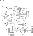
- Fig. 1 shows a first drive unit 2 that drives a pair of front wheels 1R and 1L
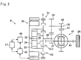
- Fig. 2 shows a second drive unit 4 that drives a pair of rear wheels 3R and 3L
- the hybrid vehicle is provided with an engine 5, a first motor 6 (abbreviated as "MG1” in the drawings) and a second motor 7 (abbreviated as "MG2" in the drawings).
- the first motor 6 is a motor-generator having a generating function.
- a speed of the engine 5 is controlled by the first motor 6, and the second motor 7 is driven by electric power generated by the first motor 6 to generate a drive force for propelling the vehicle.
- the second motor 7 may also be used as the motor-generator having a generating function.
- the first motor 6 serves as a first rotary machine.
- a power split mechanism 8 as a transmission is connected to the engine 5.
- the power split mechanism 8 includes a power split section 9 that distributes the engine torque to the first motor side and to an output side, and a transmission section 10 that alters a torque split ratio.
- the power split section 9 comprises: a sun gear 11; a ring gear 12 as an internal gear arranged concentrically with the sun gear 11; pinion gears 13 interposed between the sun gear 11 and the ring gear 12 while being meshed with both gears 11 and 12; and a carrier 14 supporting the pinion gears 13 in a rotatable manner.
- the sun gear 11 serves mainly as a reaction element
- the ring gear 12 serves mainly as an output element
- the carrier 14 serves mainly as an input element.
- An output shaft 15 of the engine 5 is connected to an input shaft 16 of the power split mechanism 8 connected to the carrier 14 so that power of the engine 5 is applied to the carrier 14.
- an additional gear unit may be interposed between the input shaft 16 and the carrier 14, and a damper device and a torque converter may be interposed between the output shaft 15 and the input shaft 16.
- the sun gear 11 is connected to the first motor 6.
- the power split section 9 and the first motor 6 are arranged concentrically with a rotational center axis of the engine 5, and the first motor 6 is situated on an opposite side of the engine 5 across power split section 9.
- the transmission section 10 is interposed coaxially between the power split section 9 and the engine 5.
- the transmission section 10 is a single pinion planetary gear unit comprising: a sun gear 17; a ring gear 18 as an internal gear arranged concentrically with the sun gear 17; pinion gears 19 interposed between the sun gear 17 and the ring gear 18 while being meshed with both gears 17 and 18; and a carrier 20 supporting the pinion gears 19 in a rotatable manner.
- the transmission section 10 is also adapted to perform a differential action among the sun gear 17, the ring gear 18, and the carrier 20.
- the sun gear 17 is connected to the ring gear 12 of the power split section 9, and the ring gear 18 is connected to an output gear 21.
- a first clutch CL1 is disposed to selectively connect the carrier 20 of the transmission section 10 with the carrier 14 of the power split section 9.
- a wet-type multiple plate clutch or a dog clutch may be used as the first clutch CL1.
- the power split section 9 is connected to the transmission section 10 to serve as a complex planetary gear unit by bringing the first clutch CL1 into engagement.
- the carrier 14 of the power split section 9 is connected to the carrier 20 of the transmission section 10 to serve as an input element, the sun gear 11 of the power split section 9 serves as a reaction element, and the ring gear 18 of the transmission section 10 serves as an output element.
- a second clutch CL2 is disposed to rotate the rotary elements of the transmission section 10 integrally.
- a friction clutch and a dog clutch may also be used as the second clutch CL2 to selectively connect the carrier 20 to the ring gear 18 or the sun gear 17, or to connect the sun gear 17 to the ring gear 18.
- the second clutch CL2 is adapted to connect the carrier 20 to the ring gear 18 to rotate the rotary elements of the transmission section 10 integrally.
- the first clutch CL1 and the second clutch CL2 are arranged coaxially with the engine 5, the power split section 9, and the transmission section 10 on the opposite side of the power split section 9 across the transmission section 10.
- the first clutch CL1 and the second clutch CL2 may be arranged not only in parallel to each other in a radial direction but also in tandem in an axial direction.
- the first clutch CL1 and the second clutch CL2 are arranged radially parallel to each other and hence an axial length of the drive unit can be shortened.
- the number of friction plates of the frictional clutch can be reduced.
- a counter shaft 22 extends parallel to a common rotational axis of the engine 5, the power split section 9, and the transmission section 10.
- a driven gear 23 is fitted onto one end of the counter shaft 22 to be meshed with the output gear 21, and a drive gear 24 is fitted onto the other end of the counter shaft 22 to be meshed with a ring gear 26 of a differential gear unit 25 as a final reduction.
- the driven gear 23 is also meshed with a drive gear 28 fitted onto a rotor shaft 27 of the second motor 7 so that power or torque of the second motor 7 is synthesized with power or torque of the output gear 21 at the driven gear 23 to be distributed from the differential gear unit 25 to the front wheels 1R and 1L via each of the drive shafts 29.
- a first brake B1 is arranged in the first drive unit 2.
- a frictional engagement device or a dog brake may be used as the first brake B1.
- the carrier 14 of the power split section 9 and the carrier 20 of the transmission section 10 are allowed to serve as reaction elements, and the sun gear 11 of the power split section 9 is allowed to serve as an input element by applying the first brake B1 to halt the output shaft 15 or the input shaft 16.
- the first brake B1 may be adapted to stop the rotation of the output shaft 15 or the input shaft 16 not only completely but also incompletely to apply a reaction torque to those shafts.
- a one-way clutch may be used instead of the first brake B1 to restrict a reverse rotation of the output shaft 15 or the input shaft 16.
- the second drive unit 4 is mounted on the hybrid vehicle to deliver a power or a torque of a rear motor 30 to a pair of rear wheels 3R and 3L.
- a motor-generator having a generating function may also be used as the rear motor 30 (abbreviated as "MGR" in the drawings), and the rear motor 30 is connected to a transmission 31.
- a gear stage of the transmission 31 may be selected from a speed reducing stage in which the torque of the rear motor 30 is multiplied, and a fixed stage in which the torque of the rear motor 30 is transmitted without being multiplied.
- the transmission 31 is a single-pinion planetary gear unit comprising: a sun gear 32; a ring gear 33 as an internal gear arranged concentrically with the sun gear 32; pinion gears 34 interposed between the sun gear 32 and the ring gear 33 while being meshed with both gears 32 and 33; and a carrier 35 supporting the pinion gears 34 in a rotatable manner.
- the sun gear 32 is connected to the rear motor 30 to serve as an input element, and the carrier 35 is connected to an output shaft 36 to serve as an output element.
- a third clutch CL3 is arranged in the second drive unit 4.
- a friction clutch and a dog clutch may also be used as the third clutch CL3 to selectively connect the sun gear 32 to the ring gear 33 or the carrier 35, or to connect the ring gear 33 to the carrier 35.
- the third clutch CL3 is adapted to connect the ring gear 33 to the carrier 35 to establish the fixed stage in the transmission 31.
- a second brake B2 is arranged in the second drive unit 4.
- a frictional engagement device or a dog brake may also be used as the second brake B2.
- the second brake B2 stops a rotation of the ring gear 33 of the transmission 31 by engaging the ring gear 33 with a casing C holding the second drive unit 4 so that the ring gear 33 is allowed to serve as a reaction element.
- the second brake B2 may be adapted to stop the rotation of the ring gear 33 not only completely but also incompletely.
- a drive gear 37 is fitted onto the output shaft 36 of the transmission 31, and a counter shaft 38 extends parallel to the output shaft 36.
- a driven gear 39 is fitted onto one end of the counter shaft 38 to be meshed with the drive gear 37.
- the driven gear 39 is diametrically larger than the drive gear 37 so that an output torque of the transmission 31 is transmitted through the driven gear 39 while being multiplied.
- a drive gear 40 is fitted onto the other end of the counter shaft 38 to be meshed with a ring gear 42 of a differential gear unit 41 as a final reduction.
- the differential gear unit 41 is connected to driveshafts 43 to deliver the power of the rear motor 30 to the right rear wheel 3R and the left rear wheel 3L.
- a first power control system 44 is connected to the first motor 6, a second power control system 45 is connected to the second motor 7, and a third power control system 46 is connected to the rear motor 30.
- Each of the first power control system 44, the second power control system 45, and the third power control system 46 individually includes an inverter and a converter.
- the first power control system 44, the second power control system 45, and the third power control system 46 are connected to one another, and also connected individually to a battery 47 including a lithium ion battery and a capacitor.
- a battery 47 including a lithium ion battery and a capacitor.
- the battery 47 is cooled by a cooling fan F as a cooling device.
- the second motor 7 and the rear motor 30 serve as a second rotary machine.
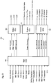
- the hybrid vehicle is provided with an electronic control unit (to be abbreviated as the "ECU” hereinafter) 48 as a controller.
- the ECU 48 is composed mainly of a microcomputer, and as shown in Fig. 3 , the ECU 48 comprises a main ECU 49, a motor ECU 50 (abbreviated as "MG-ECU” in the drawings), an engine ECU 51, and a clutch ECU 52.
- the main ECU 49 is configured to execute a calculation based on incident data from sensors as well as maps and formulas installed in advance, and transmits a calculation result to the motor ECU 50, the engine ECU 51, and the clutch ECU 52 in the form of command signal.
- the main ECU 49 receives data about; a vehicle speed; an accelerator position; a speed of the first motor 6; a speed of the second motor 7; a speed of the rear motor 30; a speed of the output shaft 15 of the engine 5; an output speed such as a speed of the ring gear 18 of the transmission section 10 or the counter shaft 22; strokes of pistons of the clutches CL1, CL2, CL3, the brakes B1, and B2; a temperature of the battery 47; temperatures of the ECUs 44, 45, and 46; a temperature of the first motor 6; a temperature of the second motor 7; a temperature of the rear motor 30; a temperature of oil (i.e., ATF) lubricating the power split mechanism 8 and the transmission 31; and a state
- command signals of output torques and speeds of the first motor 6, the second motor 7 and the rear motor 30 are transmitted from the main ECU 49 to the motor ECU 50.
- command signals of an output torque and a speed of the engine 5 are transmitted from the main ECU 49 to the engine ECU 51.
- command signals of torque transmitting capacities (including "0") of the clutches CL1, CL2, CL3, and the brakes B1, B2 are transmitted from the main ECU 49 to the clutch ECU 52.
- the motor ECU 50 calculates current values applied to the first motor 6, the second motor 7, and the rear motor 30 based on the data transmitted from the main ECU 49, and transmits calculation results to the motors 6, 7, and 30 in the form of command signals.
- an AC motor is used individually as the first motor 6, the second motor 7, and the rear motor 30.
- the command signal transmitted from the motor ECU 50 includes command signals for controlling a frequency of a current generated by the inverter and a voltage value boosted by the converter.
- the engine ECU 51 calculates current values to control opening degrees of an electronic throttle valve, an EGR (Exhaust Gas Restriction) valve, an intake valve, and an exhaust valve, and to activate an ignition plug, based on the data transmitted from the main ECU 49, and transmits calculation results to the valves and the plug in the form of command signals.
- the engine ECU 51 transmits command signals for controlling a power, an output torque and a speed of the engine 5.
- the clutch ECU 52 calculates current values supplied to actuators controlling engagement pressures of the clutches CL1, CL2, CL3, and the brakes B1, B2, based on the data transmitted from the main ECU 49, and transmits calculation results to the actuators in the form of command signals.
- the main ECU 49 also calculates a current value applied to the cooling fan F taking account of a temperature of the battery 47, and transmits calculation results to an actuator for activating the cooling fan in the form of command signal.
- an operating mode may be selected from a hybrid mode (to be abbreviated as the "HV mode” hereinafter) in which the hybrid vehicle is propelled by a drive torque generated by the engine 5, and an electric vehicle mode (to be abbreviated as the “EV mode” hereinafter) in which the hybrid vehicle is propelled by drive torques generated by the first motor 6 and the second motor 7 without using the engine 5.
- the HV mode may be selected from a hybrid-low mode (to be abbreviated as the "HV-Lo mode” hereinafter) as a first mode of the embodiment, a hybrid-high mode (to be abbreviated as the "HV-Hi mode” hereinafter) as a second mode of the embodiment, and a fixed mode.
- a rotational speed of the engine 5 (i.e., a rotational speed of the input shaft 16) is increased higher than a rotational speed of the ring gear 18 of the transmission section 10 when a rotational speed of the first motor 6 is reduced substantially to zero.
- a rotational speed of the engine 5 is reduced lower than a rotational speed of the ring gear 18 of the transmission section 10 when a rotational speed of the first motor 6 is reduced substantially to zero.
- the engine 5 and the ring gear 18 of the transmission section 10 are always rotated at substantially same speeds.
- the EV mode may be selected from a dual-motor mode in which both of the first motor 6 and the second motor 7 generate drive torques to propel the hybrid vehicle, and a single-motor mode in which only the second motor 7 generates a drive torque to propel the hybrid vehicle.
- the dual-motor mode may be selected from an electric vehicle-low mode (to be abbreviated as the "EV-Lo mode” hereinafter) in which a torque of the first motor 6 is multiplied by a relatively larger factor, and an electric vehicle-high mode (to be abbreviated as the "EV-Hi mode” hereinafter) in which a torque of the first motor 6 is multiplied by a relatively smaller factor.
- the hybrid vehicle is powered only by the second motor 7, while engaging the first clutch CL1, while engaging the second clutch CL2, or while disengaging both of the first clutch CL1 and the second clutch CL2.
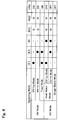
- Fig. 4 shows engagement states of the first clutch CL1, the second clutch CL2, and the first brake B1, and operating conditions of the first motor 6, the second motor 7, and the engine 5 in each operating mode.
- “ ⁇ ” represents that the engagement device is in engagement
- “-” represents the engagement device is in disengagement
- "G” represents that the motor serves mainly as a generator
- “M” represents that the motor serves mainly as a motor
- blank represents that the motor serves as neither a motor nor a generator or that the motor is not involved in propulsion of the hybrid vehicle
- "ON” represents that the engine 5 generates a drive torque
- “OFF” represents that the engine 5 does not generate a drive torque.
- an output power of the engine 5 may be translated entirely into an electric energy by operating the first motor 6 as a generator.
- the status of the engine 5 is indicated as "OFF" in Fig. 3 .
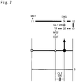
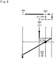
- Rotational speeds of the rotary elements of the power split mechanism 8, and directions of torques of the engine 5, the first motor 6, and the second motor 7 in each operating mode are indicated in figs. 5 to 10 .
- distances among the vertical lines represents a gear ratio of the power split mechanism 8
- a vertical distance on the vertical line from the horizontal base line represents a rotational speed of the rotary member
- an orientation of the arrow represents a direction of the torque
- a length of the arrow represents a magnitude of the torque.
- any one of the first clutch CL1 and the second clutch CL2 is engaged, and the engine 5 generates a drive torque while establishing a reaction torque by the first motor 6.
- a rotational speed of the first motor 6 is controlled in such a manner as to optimize a total energy efficiency in the first drive unit 2 including a fuel efficiency of the engine 5 and a driving efficiency of the first motor 6.
- the total energy efficiency in the first drive unit 2 may be calculated by dividing a total energy consumption by a power to rotate the front wheels 1R and 1L.
- a rotational speed of the first motor 6 may be varied continuously, and the rotational speed of the engine 5 is governed by the rotational speed of the first motor 6 and a vehicle speed. That is, the power split mechanism 8 may serve as a continuously variable transmission.
- the first motor 6 may serve as a generator. In this situation, therefore, a power of the engine 5 is partially translated into an electric energy, and the remaining power of the engine 5 is delivered to the ring gear 18 of the transmission section 10.
- Such split ratio between the torque delivered from the engine 5 to the first motor 6 side through the power split mechanism 8 and the torque delivered from the engine 5 to the ring gear 18 differs between the HV-Lo mode and the HV-Hi mode.
- a ratio of the torque applied to the ring gear 18 in the HV-Lo mode may be expressed as "1/( ⁇ 1 ⁇ 2)", and a ratio of the torque applied to the ring gear 18 in the HV-Hi mode may be expressed as "1/( ⁇ 1)”.
- a ratio of the torque of the engine 5 delivered to the ring gear 18 in the HV-Lo mode may be expressed as "1/(1-( ⁇ 1 ⁇ 2))”
- a ratio of the torque of the engine 5 delivered to the ring gear 18 in the HV-Hi mode may be expressed as "1/( ⁇ 1+1)".
- ⁇ 1 is a gear ratio of the power split section 9 (i.e., a ratio between teeth number of the ring gear 12 and teeth number of the sun gear 11)
- ⁇ 2 is a gear ratio of the transmission section 10 (i.e., a ratio between teeth number of the ring gear 18 and teeth number of the sun gear 17).
- ⁇ 1 and “ ⁇ 2" are individually smaller than "1". That is, in the HV-Lo mode, a ratio of the torque delivered to the ring gear 18 is increased in comparison with that in the HV-Hi mode.
- 1/(1-( ⁇ 1 ⁇ 2)) corresponds to a first predetermined ratio of the embodiment
- "1/( ⁇ 1+1)” corresponds to a second predetermined ratio of the embodiment.
- the ring gear 18 and the driven gear 23 serve as an output member in the embodiment.
- the output torque of the engine 5 is calculated by subtracting a torque required to increase the speed of the engine 5 from a torque generated by the engine 5.
- the electric power generated by the first motor 6 is supplied to the second motor 7, and in addition, the electric power accumulated in the battery 47 is also supplied to the second motor 7 as necessary.
- the second motor 7 and the rear motor 30 are used to assist the drive torque generated by the engine 5. That is, the rear motor 30 may also be controlled in a similar manner as the second motor 7. In the following explanation, however, an example to assist the drive torque only by the second motor 7 will be explained.
- both of the first clutch CL1 and the second clutch CL2 are engaged so that all of the rotary elements in the power split mechanism 8 are rotated at a same speed.
- the output power of the engine 5 will not be translated into an electric energy by the first motor 6 and the second motor 7. For this reason, a power loss associated with such energy conversion will not be caused in the fixed mode and hence power transmission efficiency can be improved.
- a ratio of a rotational speed of the ring gear 18 of the transmission section 10 to a rotational speed of the first motor 6 is reduced smaller than that in the EV-Hi mode.
- a speed reducing ratio in the HV-Lo mode is greater than that in the HV-Hi mode so that a greater drive force is established in the EV-Lo mode.
- the operating mode is selected on the basis of an SOC level of the battery 47, a vehicle speed, a required drive force and so on.
- a selection pattern of the operating mode may be selected from a CS (i.e., Charge Sustaining) mode in which the operating mode is selected in such a manner as to maintain the SOC level of the battery 47 as far as possible, and a CD (i.e., Charge Depleting) mode in which the operating mode is selected in such a manner as to propel the hybrid vehicle while consuming the electric power accumulated in the battery 47.
- CS i.e., Charge Sustaining
- CD Charge Depleting
- the CS mode is selected when the SOC level of the battery 47 is relatively low
- the CD mode is selected when the SOC level of the battery 47 is relatively high.
- Fig. 11 shows an example of a map used to select the operating mode during propulsion in the CS mode.
- the vertical axis represents a required drive force
- the horizontal axis represents a vehicle speed.
- the vehicle speed may be detected by a vehicle speed sensor
- the required drive force may be estimated based on an accelerator position detected by an accelerator sensor.
- the hatched area is an area where the single-motor mode is selected.
- the single-motor mode is selected when the hybrid vehicle is propelled in a reverse direction irrespective of the required drive force, and when the hybrid vehicle is propelled in a forward direction and the required drive force is small (or when decelerating).
- Such area where the single-motor mode is selected is determined based on specifications of the second motor 7 and the rear motor 30.
- the HV mode is selected when the large drive force is required.
- the drive force may be generated from a low speed range to a high speed range.
- the SOC level falls close to a lower limit level, therefore, the HV mode may be selected even if an operating point governed by the required drive force and the vehicle speed falls within the hatched area.
- the HV mode may be selected from the HV-Lo mode, the HV-Hi mode, and the fixed mode.
- the HV-Lo mode is selected when the vehicle speed is relatively low and the required drive force is relatively large
- the HV-Hi mode is selected when the vehicle speed is relatively high and the required drive force is relatively small
- the fixed mode is selected when the operating point falls between an area where the HV-Lo mode is selected and an area where the HV-Hi mode is selected.
- the operating mode is shifted from the fixed mode to the HV-Lo mode when the operating point is shifted across the "Lo ⁇ Fix" line from right to left, or when the operating point is shifted across the "Lo ⁇ Fix” line upwardly from the bottom.
- the operating mode is shifted from the HV-Lo mode to the fixed mode when the operating point is shifted across the "Lo ⁇ Fix" line from left to right, or when the operating point is shifted across the "Lo ⁇ Fix” line downwardly from the top.
- the operating mode is shifted from the HV-Hi mode to the fixed mode when the operating point is shifted across the "Fix ⁇ Hi” line from right to left, or when the operating point is shifted across the "Fix ⁇ Hi” line upwardly from the bottom.
- the operating mode is shifted from the fixed mode to the HV-Hi mode when the operating point is shifted across the "Fix ⁇ Hi” line from left to right, or when the operating point is shifted across the "Fix ⁇ Hi” line downwardly from the top.
- Fig. 12 shows an example of a map used to select the operating mode during propulsion in the CD mode.
- the vertical axis also represents the required drive force
- the horizontal axis also represents the vehicle speed.
- the hatched area is also an area where the single-motor mode is selected.
- the single-motor mode is selected when the hybrid vehicle is propelled in a reverse direction irrespective of the required drive force, and when the hybrid vehicle is propelled in a forward direction and the required drive force is smaller than a first threshold force value F1 (or when decelerating).
- Such area where the single-motor mode is selected is also determined based on specifications of the second motor 7 and the rear motor 30.
- the dual-motor mode is selected when the drive force greater than the first threshold force value F1 is required.
- the HV mode is selected when the vehicle speed is higher than a first threshold speed VI, or when the vehicle speed is higher than a second threshold speed V2 and the required drive force is greater than a second threshold force value F2.
- the drive force may be generated from the low speed range to the high speed range in the HV mode.
- the HV mode may be selected even if the operating point falls within the areas where the single-motor mode and the dual-motor mode are selected.
- the HV-Lo mode is also selected when the vehicle speed is relatively low and the required drive force is relatively large
- the HV-Hi mode is also selected when the vehicle speed is relatively high and the required drive force is relatively small
- the fixed mode is also selected when the operating point falls between the area where the HV-Lo mode is selected and the area where the HV-Hi mode is selected.
- the operating mode is shifted between the fixed mode and the HV-Lo mode when the operating point is shifted across the "Lo ⁇ Fix" line. Likewise, the operating mode is shifted from the HV-Hi mode and the fixed mode when the operating point is shifted across the "Fix ⁇ Hi".
- the areas of each of the operating mode and the lines defining the areas may be altered depending on temperatures of the members of the first drive unit 2, the battery 47, the power control systems 44, 45, and46, and the SOC level of the battery 47.
- the upper limit power of the engine 5 is governed by an upper limit speed of the engine 5.
- the upper limit speed of the engine 5 is determined based on upper limit speeds of the pinion gears 13 of the power split section 9, the first motor 6 and so on.
- the horizontal axis represents a vehicle speed
- a vertical axis represents an upper limit speed of the engine 5.
- the line Npin1-Lo indicates a change in the upper limit speed of the engine 5 set on the basis of the upper limit speed of the pinion gear 13 during propulsion in the HV-Lo mode.
- the upper limit speed of the engine 5 is increased mildly with an increase in the vehicle speed.
- the line Ng-Lo indicates a change in the upper limit speed of the engine 5 set on the basis of the upper limit speed of the first motor 6 during propulsion in the HV-Lo mode.
- the upper limit speed of the engine 5 is increased at a relatively larger rate with an increase in the vehicle speed.
- the upper limit speed of the engine 5 set on the basis of the upper limit speed of the pinion gear 13 is lower than the upper limit speed of the engine 5 set on the basis of the upper limit speed of the first motor 6 over the entire speed range.
- the rotational speed of the engine 5 is limited based on the upper limit speed of the pinion gear 13. Accordingly, the sun gears 11, 17, the ring gears 12, 18, the pinion gears 13, 19, and the carriers 14, 20 correspond to "a plurality of rotary members", and the sun gear 11 connected to the pinion gears 13 and the first motor 6 corresponds to a "predetermined rotary member" of the embodiment.
- the dashed line Npin1-Hi indicates a change in the upper limit speed of the engine 5 set on the basis of the upper limit speed of the pinion gear 13 during propulsion in the HV-Hi mode.
- the upper limit speed of the engine 5 set on the basis of upper limit speed of the pinion gear 13 is higher in the HV-Hi mode over the entire speed range in comparison with that in the HV-Lo mode.
- an increasing rate of the upper limit speed of the engine 5 set on the basis of upper limit speed of the pinion gear 13 in the HV-Hi mode is substantially identical to that in the HV-Lo mode.
- the dashed line Ng-Hi indicates a change in the upper limit speed of the engine 5 set on the basis of the upper limit speed of the first motor 6 during propulsion in the HV-Hi mode.
- the upper limit speed of the engine 5 is increased mildly with an increase in the vehicle speed.
- the upper limit speed of the engine 5 set on the basis of the upper limit speed of the first motor 6 is lower than the upper limit speed of the engine 5 set on the basis of the upper limit speed of the pinion gear 13 over the entire speed range.
- the rotational speed of the engine 5 is limited based on the upper limit speed of the first motor 6.
- the upper limit speed of the engine 5 in the HV-Hi mode is higher than that in the HV-Lo mode.
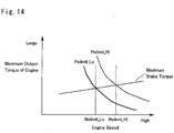
- FIG. 14 Upper limit powers of the engine 5 in the HV-Lo mode and the HV-Hi mode are indicated in Fig. 14 .
- the horizontal axis represents an engine speed
- the vertical axis represents a maximum output torque of the engine 5.
- the maximum output torque of the engine 5 increases gradually after the engine speed exceeds a predetermined speed Ne 1.
- the upper limit power of the engine 5 may be obtained by multiplying a maximum output torque of the engine 5 by an upper limit speed of the engine 5.
- the upper limit power of the engine 5 in the HV-Lo mode is indicated by a solid curve Pelimit_Lo
- the upper limit power of the engine 5 in the HV-Hi mode is indicated by a dashed curve Pelimit_Hi.
- the upper limit power of the engine 5 is greater in the HV-Hi mode than that in the HV-Lo mode.
- an upper limit speed of the engine 5 in the HV-Lo mode is indicated by the vertical dashed line Nelimit_Lo
- an upper limit speed of the engine 5 in the HV-Hi mode is indicated by the vertical dashed line Nelimit_Hi.
- the ratio of the torque delivered to the output side is greater than that in the HV-Hi mode. Accordingly, even if the upper limit power of the engine 5 in the HV-Lo mode is smaller than that in the HV-Hi mode, the power (or the torque) delivered to the ring gear 18 is increased.
- an amount of energy regenerated by the first motor 6 in the HV-Lo mode may be smaller than that in the HV-Hi mode.
- the drive force in the HV-Lo mode and the drive force in the HV-Hi mode may be calculated by adding a torque delivered from the ring gear 18 to an output torque of the second motor 7.
- the electricity generated by the first motor 6 and the electricity accumulated in the battery 47 may be supplied to the second motor 7. That is, when the electric power can be supplied sufficiently from the battery 47 to the second motor 7 to generate the rated torque, to the second motor 7 is allowed to generate the maximum torque irrespective of a generation amount of the first motor 6.
- the maximum output torque of the second motor will not be changed in the HV-Lo mode and the HV-Hi mode.
- the maximum drive force to propel the vehicle is governed by an output power (or torque) of the ring gear 18 and an output power of the second motor 7. For this reason, a larger drive force may be generated in the HV-Lo mode than the HV-Hi mode in a difference in a magnitude of the output power (or torque) of the ring gear 18.
- a definition of the "maximum drive force" is an upper limit value of an available drive force taking account of a speed restriction on the rotary members and so on.
- the electric power may not be supplied sufficiently from the battery 47 to the second motor 7.
- a total value of the electric power supplied to the second motor 7 varies depending on a generation amount of the first motor 6. For example, in the HV-Lo mode in which the ration of the power delivered to the first motor 6 side is small, the electric power supplied to the second motor 7 is reduced from that in the HV-Hi mode.
- an output power of the battery 47 may also be restricted by a temperature of the second power control system 45. According to the embodiment, therefore, the upper limit power possible to be supplied to the battery 47 is determined taking account of conditions of the battery 47 and the second power control system 45.
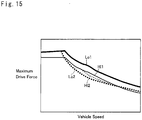
- Fig. 15 indicates a change in the maximum drive force in accordance with the available output power of the battery 47.
- the horizontal axis represents a vehicle speed
- the vertical axis represents the maximum drive force
- the curve Lo1 represents the maximum drive force of a case in which the battery 47 can output sufficient power in the HV-Lo mode
- the curve Lo2 represents the maximum drive force of a case in which the available output power of the battery 47 is restricted in the HV-Lo mode
- the curve Hi1 represents the maximum drive force of a case in which the battery 47 can output sufficient power in the HV-HI mode
- the curve Ho2 represents the maximum drive force of a case in which the available output power of the battery 47 is restricted in the HV-Hi mode.
- the maximum drive force in the HV-Lo mode and the maximum drive force in the HV-Hi mode are changed in accordance with the output power of the battery 47. Specifically, when the battery 47 can output the electric power sufficiently, a larger maximum drive force can be generated in the HV-Lo mode. By contrast, when the available output power of the battery 47 is restricted or small, a larger maximum drive force can be generated in the HV-Hi mode.
- the control system is configured to execute the routine shown in Fig. 16 .
- step S1 it is determined whether or not a vehicle speed V is higher than a first predetermined speed Vs1.
- the first predetermined speed Vs1 is set to a level possible to generate the drive force comparable to that of the case in which the electric power can be supplied from the battery 47 sufficiently to the second motor 7, even if the output power of the battery 47 supplied to the second motor 7 is restricted.
- the first predetermined speed Vs1 is set on the basis of a base speed of the second motor 7 in such a manner that the output torque of the second motor 7 is kept constant irrespective of the rotational speed of the second motor 7.
- the base speed is reduced to a lower speed with a reduction in the available electric power supplied to the second motor 7.
- the first predetermined speed Vs1 may be set in accordance with the electric power possible to be supplied from the battery 47 to the second motor 7.
- the first predetermined speed Vs1 may be set to a fixed value at which the electric power can be supplied from the battery 47 sufficiently to the second motor 7, even if the available output power of the battery 47 falls to a lower limit value.
- the first predetermined speed Vs1 corresponds to a "predetermined vehicle speed" of the embodiment.
- step S1 it is determined whether or not the electric power possible to be supplied from the battery 47 to the second motor 7 is reduced to a level at which the drive force to be generated in the HV-Lo mode is reduced lower than the drive force to be generated in the HV Hi mode.
- the electric power possible to supply from the battery 47 to the second motor 7 is governed by the available output power of the battery 47 and a limit value of the electric power applied to the second power control system 45. As described, the available output power of the battery 47 is governed by the temperature and the SOC level of the battery 47. In the routine shown in Fig.
- the first threshold power W1 may be set based on a result of an experimentation or simulation.
- the first threshold power W1 is set to a value possible to fulfill the following relations (1) Wg+Wout ⁇ Wm, and (2) Tr_Lo-Tr_Hi ⁇ Ts-Tm_Lo.
- Wg is a power generated by the first motor 6 by maintaining the engine speed to the upper limit speed Nelimit_Hi in the HV-Hi mode
- Wout is a power corresponding to the first threshold power W1
- Wm is a power consumed by the second motor 7 by generating a rated torque by the second motor 7 at a current vehicle speed.
- Tr_Lo is a torque expected to be delivered to the ring gear 18 by rotating the engine 5 at the upper limit speed Nelimit_Lo in the HV-Lo mode
- Tr_Hi is a torque expected to be delivered to the ring gear 18 by rotating the engine 5 at the upper limit speed Nelimit_Hi in the HV-Hi mode
- Ts is the rated torque of the second motor 7 at a current vehicle speed
- Tm_Lo is an output torque of the second motor 7 generated by controlling the second motor 7 in such a manner as to adjust the output power to the battery 47 within the first threshold power W1, while controlling the first motor 6 in such a manner as to maintain the engine speed to the upper limit speed Nelimit_Lo in the HV-Lo mode.
- the maximum drive forces in the HV-Hi mode and the HV-Lo mode in accordance with the available output power to the battery 47 may also be determined in advance based on a result of experimentation or simulation.
- the output power from the battery 47 possible to reduce the maximum drive force in the HV-Lo mode smaller than the maximum drive force in the HV-Hi mode may be employed as the first threshold power W1.
- the first threshold power W1 may be set larger than the value possible to reduce the maximum drive force in the HV-Lo mode smaller than the maximum drive force in the HV-Hi mode, taking account of deterioration of the thermal condition.
- step S3 the routine progresses to step S3 to restrict selection of the HV-Lo mode, and thereafter returns.
- the HV-Lo mode will not be inhibited completely.
- the current operating mode e.g., the HV-Hi mode or the fixed mode
- the rotational speed of the second motor 7 may be maintained until a predetermined period of time has elapsed, or until the rotational speed of the second motor 7 is reduced lower than the base speed, even if the condition to shift the operating mode from the HV-Hi mode or the fixed mode to the HV-Lo mode is satisfied with reference to the maps shown in Figs. 11 and 12 .
- step S4 determines whether or not the selection of the HV-Lo mode is restricted.
- a flag representing a restriction of selection of the HV-Lo mode is turned on when the restriction at step S3 is executed, and the determination at step S4 is made based on the flag.
- step S5 determines whether or not the vehicle speed V is lower than a second predetermined speed Vs2. That is, at step S5, it is determined whether or not the restriction of selection of the HV-Lo mode can be cancelled. To this end, specifically, it is determined whether or not the rotational speed of the second motor 7 is reduced lower than the base speed. Specifically, in order to reduce a frequency of the restriction of the HV-Lo mode, the second predetermined speed Vs2 is set to be lower than the first predetermined speed Vs1.
- step S6 the routine progresses to cancel the restriction of selection of the HV-Lo mode, and to turn off the flag representing the restriction of selection of the HV-Lo mode. Thereafter, the routine returns.
- step S7 the routine progresses to step S7 to determine whether or not the available output power of the battery 47 is greater than a second threshold power W2. That is, at step S7, it is also determined whether or not the restriction of selection of the HV-Lo mode can be cancelled.
- the second threshold power W2 is set to be greater than the first threshold power W1.
- step S7 If the available output power of the battery 47 is greater than the second threshold power W2 so that the answer of step S7 is YES, the routine progresses to step S6 to cancel the restriction of selection of the HV-Lo mode, and to turn off the flag representing the restriction of selection of the HV-Lo mode. Thereafter, the routine returns.
- the available output power of the battery 47 is smaller than the second threshold power W2 so that the answer of step S7 is NO, the routine returns. That is, the restriction of selection of the HV-Lo mode is continued.
- Fig. 17 indicates temporal changes in the available output power of the battery 47 and the restriction of selection of the HV-Lo mode, after accelerating the stopping hybrid vehicle to a predetermined speed and then decelerate the hybrid vehicle.
- the hybrid vehicle is launched at point t0.
- a speed of the hybrid vehicle reaches the predetermined speed at point t4, and gradually reduced after point t4.
- the SOC level of the battery 47 falls gradually from point t0, and after the vehicle speed reaches the predetermined speed, the SOC level of the battery 47 starts falling moderately.
- the temperature of the battery 47 is raised from point t0 as a result of power output from the battery 47.
- the maximum output power of the battery 47 is governed by the SOC level and the temperature of the battery 47. In the example shown in Fig. 17 , therefore, the maximum output power of the battery 47 is increased from point t0 to point t3 mainly by a temperature rise itself. Then, the temperature of the battery 47 reaches the upper limit value at point t5 and the SOC level of the battery 47 keeps falling in this situation. Therefore, the maximum output of the battery 47 is maintained substantially constant until point t5, and decreases gradually from point t5.
- the vehicle speed exceeds the first predetermined speed Vs1, and the maximum output power of the battery 47 is smaller than the first threshold power W1. In this situation, therefore, the selection of the HV-Lo mode is restricted.
- the available output power of the battery 47 exceeds the second threshold power W2, and the restriction of selection of the HV-Lo mode is cancelled at point t2.
- the available output power of the battery 47 starts decreasing from point t5, and when the available output power of the battery 47 falls below the first threshold power W1 at point t6, the selection of the HV-Lo mode is restricted again.
- the routine shown in Fig. 16 progresses from step S1 to step S2.
- selection of the HV-Lo mode is restricted when the available output power of the battery 47 decreases to the extent that the maximum drive force expected to be established in the HV-Lo mode based on the current condition is reduced smaller than the maximum drive force expected to be established in the HV-Hi mode based on the current condition. According to the embodiment, therefore, the maximum drive force will not be restricted by the limitation of the available output power of the battery 47.
- the low speed range lower than the first predetermined speed Vs1 and the second predetermined speed Vs2
- selection of the HV-Lo mode will not be restricted. According to the embodiment, therefore, the maximum drive force will not be restricted in the low speed range. Specifically, in the low speed range, the drive force indicated by the dashed lime shown in Fig. 15 can be established, and in the remaining speed range, the drive force indicated by the solid line shown in Fig. 15 can be established.
- steps S1 and S5 may be omitted. That is, the restriction of the HV-Lo mode may also be determined without reference to the vehicle speed. In this case, the routine progresses directly from step S4 to step S7 if the answer of step S4 is YES.
- the power generation of the first motor 6 is increased with an increase in the upper limit power of the engine 5. That is, even if the second motor 7 is supplied small amount of electric power from the battery 47, the electric power will be supplied sufficiently to the second motor 7 by generating the electric power by the first motor 6. According to the embodiment, therefore, the first threshold power W1 may be reduced with an increase in the upper limit power of the engine 5 in the HV-Lo mode.
- the determination at step S2 may be made with reference to a map shown in Fig. 18 .
- the map shown in Fig. 18 may be prepared based on a result of an experimentation or a simulation, and in Fig. 18 , the horizontal axis represents the upper limit power of the engine 5 in the HV-Lo mode, and the vertical axis represents the first threshold power W1.
- the upper limit power of the engine 5 is set on the basis of the allowable speed of the pinion gear 13 as an upper limit speed at which the pinion gear 13 can be rotated without being damaged. Accordingly, as shown in Fig. 19 , the allowable speed of the pinion gear 13 may be reduced with an increase in a temperature of the pinion gear 13. Instead, as shown in Fig. 20 , the allowable speed of the pinion gear 13 may be increased with an increase in an amount of lubricant (i.e., oil) supplied to the pinion gear 13. By thus adjusting the allowable speed of the pinion gear 13, the output power of the engine 5 will not be restricted excessively to prevent shortage of the drive force.
- lubricant i.e., oil
- a temperature sensor may be arranged in the vicinity of the pinion gears 13 to measure a temperature of the pinion gears 13.
- the temperature of the pinion gear 13 may be estimated based on a magnitude of the torque applied to the pinion gear 13, or based on an oil temperature in the first drive unit 2.
- control system may be further configured to execute a cancellation control to increase the available output power of the battery 47 during restricting the selection of the HV-Lo mode.
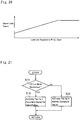
- Fig. 21 An example of the cancellation control is shown in Fig. 21 .
- the routine shown in Fig. 21 is commenced when the available output power of the battery 47 is limited due to temperature rise in the battery 47.
- step S11 it is determined whether or not the selection of the HV-Lo mode is restricted. Such determination at step S11 may be made by the same procedure as the determination at step S4 in the routine shown in Fig. 16 .
- step S11 If the selection of the HV-Lo mode is not restricted so that the answer of step S11 is NO, the routine progresses to step S12 to activate the cooling fan F based on a command signal for the normal control. Thereafter, the routine returns.
- step S13 the routine progresses to step S13 to activate the cooling fan F based on a command signal for the cancellation control. Thereafter, the routine returns.
- FIG. 22 An example of the command signal for activating the cooling fan F is shown in Fig. 22 .
- the horizontal axis represents a temperature of the battery 47
- the vertical axis represents a current value applied to the cooling fan F
- the solid line represents a current value applied to the cooling fan F when carrying out the cancellation control
- the dashed line represents a current value applied to the cooling fan F in the normal condition.
- a relatively large current is applied to the cooling fan F from a relatively low temperature. In this case, therefore, the battery 47 can be cooled promptly to ease the limitation of the available output power of the battery 47. In other words, the restriction of selection of the HV-Lo mode can be cancelled promptly.
- a water-cooling system may also be used instead of the cooling fan F. In this case, a flow rate of the water is increased when carrying out the cancellation control to cool the battery 47 promptly.
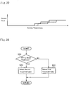
- control system is further configured to execute another cancellation control shown in Fig. 23 .
- the routine shown in Fig. 23 is executed to charge the battery 47 by increasing frequency to start the engine 5. According to the routine shown in Fig. 23 , specifically, the engine 5 is started when the required power is relatively small.
- step S21 it is determined whether or not the selection of the HV-Lo mode is restricted. Such determination at step S21 may be made by the same procedure as the determination at steps S4 and S11 in the foregoing routines. If the selection of the HV-Lo mode is not restricted so that the answer of step S21 is NO, the routine progresses to step S22 to select a first starting threshold value of the required power to start the engine 5 in the normal condition, and thereafter, the routine returns. By contrast, if the selection of the HV-Lo mode is restricted so that the answer of step S21 is YES, the routine progresses to step S23 to select a second starting threshold value of the required power to start the engine 5 that is smaller than the first starting threshold value.
- the first differential mechanism is adapted to perform a differential action among a first rotary element connected to an engine; a second rotary element connected to a motor; and a third rotary element connected to drive wheels.
- the second differential mechanism is also adapted to perform a differential action among: a fourth rotary element; a fifth rotary element connected to the third rotary element; and a sixth rotary element.
- the hybrid vehicles comprises: a first engagement device that selectively connects the sixth rotary element to the first rotary element or the second rotary element; and a second engagement device that selectively connects any two of the first rotary element, the second rotary element, and the third rotary element, or connects any two of the fourth rotary element, the fifth rotary element, and the sixth rotary element.
Landscapes
- Engineering & Computer Science (AREA)
- Chemical & Material Sciences (AREA)
- Combustion & Propulsion (AREA)
- Transportation (AREA)
- Mechanical Engineering (AREA)
- Automation & Control Theory (AREA)
- Electric Propulsion And Braking For Vehicles (AREA)
- Hybrid Electric Vehicles (AREA)
Abstract
Description
- The present disclosure claims the benefit of Japanese Patent Application No.
2017-153836 filed on August 9, 2017 - Embodiments of the present disclosure relate to the art of a drive force control system for a hybrid vehicle, in which an output torque of a rotary machine driven by electricity translated from an output torque of the engine is synthesized with the engine torque.
-
JP-A-2017-007437 JP-A-2017-007437 - A speed of the engine may be restricted to limit damage on rotary members of the power split mechanism, and a limit speed of the engine in the low mode is lower than that in the high mode. A maximum output torque of the engine gradually increases with an increase in an engine speed, and a change in the maximum output torque of the engine is smaller than that of the engine speed. That is, the upper limit power of the engine is greatly affected by the engine speed. If the engine speed is thus restricted, a maximum output torque of the engine is also restricted. Specifically, in the low mode, the upper limit power of the engine is reduced in comparison with that in the high mode.
- However, in the low mode, a ratio of the torque delivered to the output side is larger than that in the high mode, and hence the large torque may be delivered to the output side even if the output torque of the engine is restricted. That is, if it is possible to supply electricity sufficiently from a battery to the second motor, the second motor is allowed to generate a rated torque (i.e. a maximum torque) irrespective of a generation amount of the first motor. Accordingly, if the electricity can be supplied sufficiently from the battery to the second motor, a larger drive force may be generated by shifting the operating mode from the high mode to the low mode even if the engine output is restricted.
- By contrast, if the electricity cannot be supplied sufficiently from the battery to the second motor, an available output torque of the second motor is determined depending on the generation amount of the first motor. In the low mode, a ratio of the power delivered to the first motor is smaller than that in the high mode, and the output torque of the engine is restricted as explained above. For these reasons, the generation amount of the first motor is reduced in the low mode in comparison with that in the high mode. Consequently, if the electricity cannot be supplied sufficiently from the battery to the second motor, the maximum output torque of the second motor may be decreased in the low mode in comparison with that in the high mode. For this reason, if the low mode and the high mode are selected based on a unified condition, a maximum drive force may be reduced excessively when the electricity cannot be supplied sufficiently from the battery to the second motor.
- Aspects of embodiments of the present disclosure have been conceived noting the foregoing technical problems, and it is therefore an object of the present disclosure is to provide a control system for hybrid vehicles configured to prevent a reduction in a maximum drive force when electricity cannot be supplied sufficiently from the battery to the second motor.
- Driving force control system according to the embodiment of the present disclosure is applied to a hybrid vehicle comprising: an engine; a first rotary machine that is configured to translate an output power of the engine partially into an electric power; a transmission mechanism that is configured to distribute an output torque of the engine to the first rotary machine side and an output member side, wherein an operating mode can be selected from a first mode in which the output torque of the engine is delivered to the output member side at a first predetermined ratio, and a second mode in which the output torque of the engine is delivered to the output member side at a second predetermined ratio that is smaller than the first predetermined ratio; a battery; and a second rotary machine to which at least one of the electric power translated by the first rotary machine and an electric power accumulated in the battery is supplied to generate a power. The control system is configured to generate a maximum drive force to propel the vehicle by operating the engine to generate an upper limit power, while operating the second rotary machine to generate a power by supplying the electric power translated by the first rotary machine and a maximum output power of the battery to the second rotary machine. In order to achieve the above-explained objective, according to the embodiment of the present disclosure, a controller that is configured to control the transmission mechanism is configured to restrict selection of the first mode when an available output power of the battery to be supplied to the second rotary machine is smaller than a predetermined value.
- In a non-limiting embodiment, the threshold power may include an output power of the battery possible to reduce the maximum drive force in the first mode to be smaller than the maximum drive force in the second mode.
- In a non-limiting embodiment, the predetermined value may be reduced with an increase in the upper limit power of the engine.
- In a non-limiting embodiment, the upper limit power of the engine may be calculated by multiplying a maximum output torque of the engine by an upper limit speed of the engine, and the upper limit speed of the engine in the first mode may be set to be lower than the upper limit speed of the engine in the second mode.
- In a non-limiting embodiment, the transmission may comprise a plurality of rotary elements, and the upper limit speed of the engine may be raised with an increase in an upper limit speed of a predetermined rotary element in the rotary elements.
- In a non-limiting embodiment, the upper limit speed of the predetermined rotary element may be lowered with a temperature rise of the predetermined rotary element, and the upper limit speed of the predetermined rotary element may be raised with an increase in an amount of lubricant supplied to the predetermined rotary element.
- In a non-limiting embodiment, the controller may be further configured to restrict the selection of the first mode when a vehicle speed is higher than a predetermined speed.
- In a non-limiting embodiment, the controller may be further configured to execute a cancellation control to cancel the restriction of selection of the first mode by increasing the available output power of the battery supplied to the second rotary machine.
- In a non-limiting embodiment, the available output power of the battery may be restricted when a temperature of the battery is raised higher than a predetermined temperature. The drive force control system may further comprises a cooling device, and the cancellation control may include a control configured to cool the battery by the cooling device more promptly during restricting the selection of the first mode, in comparison with a case in which the selection of the first mode is not restricted.
- In a non-limiting embodiment, the controller may be further configured to: select an operating mode of the hybrid vehicle from a hybrid mode in which the hybrid vehicle is powered by the engine and the second rotary machine, and an electric vehicle mode in which the hybrid vehicle is powered by the second rotary machine without using the engine; and start the engine when a required power is greater than a predetermined power. In addition, the cancellation control may include a control configured to decrease the predetermined power when the selection of the first mode is restricted, in comparison with a case in which the selection of the first mode is not restricted.
- Thus, according to the embodiments of the present disclosure, the operating mode of the transmission can be selected from the first mode in which the output torque of the engine is delivered to the output member side at a first predetermined ratio, and the second mode in which the output torque of the engine is delivered to the output member side at the second predetermined ratio that is smaller than the first predetermined ratio. According to the embodiment, therefore, a large power may be applied to the output member through the transmission by selecting the first mode. In addition, at least one of the electric power translated by the first rotary machine and the electric power accumulated in the battery is supplied to the second rotary machine. According to the embodiment, therefore, the maximum drive force to propel the hybrid vehicle may be increased by selecting the first mode, when the electricity can be supplied sufficiently from the battery to the second motor. In the first mode, since the ratio of the power delivered to the first rotary machine side is small, the maximum drive force will be reduced significantly when the available output power of the battery to be supplied to the second rotary machine is reduced. In order to prevent such reduction in the maximum drive force, according to the embodiment, the controller is configured to restrict the selection of the first mode in such situation.
- Features, aspects, and advantages of exemplary embodiments of the present invention will become better understood with reference to the following description and accompanying drawings, which should not limit the invention in any way.
-
Fig. 1 is a skeleton diagram showing a first drive unit of the hybrid vehicle according to at least one embodiment of the present disclosure; -
Fig. 2 is a skeleton diagram showing a second drive unit of the hybrid vehicle according to at least one embodiment of the present disclosure; -
Fig. 3 is a block diagram showing a structure of an electronic control unit; -
Fig. 4 is a table showing engagement states of engagement devices and operating conditions of the prime movers in each operating mode; -
Fig. 5 is a nomographic diagram showing a situation in a HV-Hi mode; -
Fig. 6 is a nomographic diagram showing a situation in a HV-Lo mode; -
Fig. 7 is a nomographic diagram showing a situation in a fixed mode; -
Fig. 8 is a nomographic diagram showing a situation in an EV-Lo mode; -
Fig. 9 is a nomographic diagram showing a situation in an EV-Hi mode; -
Fig. 10 is a nomographic diagram showing a situation in a single mode; -
Fig. 11 shows a map for determining an operating mode during propulsion in a CS mode; -
Fig. 12 shows a map for determining an operating mode during propulsion in a CD mode; -
Fig. 13 is a graph showing an upper limit speed of the engine; -
Fig. 14 is a graph showing upper limit outputs of the engine in the HV-Lo mode and the HV-Hi mode; -
Fig. 15 is a graph showing a change in a maximum drive force in accordance with a change in the available output power of the battery; -
Fig. 16 is a flowchart showing one example of a routine executed by the control system according to the embodiment; -
Fig. 17 is a time chart showing a temporal restriction of the HV-Lo mode in accordance with a temporal change in an output power allowed to output from the battery; -
Fig. 18 is a graph showing a change in a first threshold value in accordance with a change in the upper limit output power of the engine; -
Fig. 19 is a graph showing an allowable speed of a pinion gear in accordance with a change in a temperature of the pinion gear; -
Fig. 20 is a graph showing the allowable speed of a pinion gear in accordance with a change in an amount of lubricant applied to the pinion gear; -
Fig. 21 is a flowchart showing one example of a routine to change a command signal to a cooling fan so as to increase an available output from the battery; -
Fig. 22 is a graph showing a change in the command signal to the cooling fan in accordance with a current value; and -
Fig. 23 is a flowchart showing one example of a routine to increase a frequency to start the engine so as to increase the available output from the battery. - Preferred embodiments of the present disclosure will now be explained with reference to the accompanying drawings. Referring now to
Figs. 1 and2 , there are shown the first embodiment of the hybrid vehicle according to the present disclosure. Specifically,Fig. 1 shows afirst drive unit 2 that drives a pair offront wheels Fig. 2 shows asecond drive unit 4 that drives a pair ofrear wheels 3R and 3L. The hybrid vehicle is provided with anengine 5, a first motor 6 (abbreviated as "MG1" in the drawings) and a second motor 7 (abbreviated as "MG2" in the drawings). Specifically, the first motor 6 is a motor-generator having a generating function. In the hybrid vehicle according to the first embodiment, a speed of theengine 5 is controlled by the first motor 6, and thesecond motor 7 is driven by electric power generated by the first motor 6 to generate a drive force for propelling the vehicle. Optionally, thesecond motor 7 may also be used as the motor-generator having a generating function. In the hybrid vehicle, accordingly, the first motor 6 serves as a first rotary machine. - A power split mechanism 8 as a transmission is connected to the
engine 5. The power split mechanism 8 includes a power split section 9 that distributes the engine torque to the first motor side and to an output side, and atransmission section 10 that alters a torque split ratio. - For example, a single-pinion planetary gear unit adapted to perform differential action among three rotary elements may be used as the power split section 9. Specifically, the power split section 9 comprises: a
sun gear 11; aring gear 12 as an internal gear arranged concentrically with thesun gear 11; pinion gears 13 interposed between thesun gear 11 and thering gear 12 while being meshed with bothgears carrier 14 supporting the pinion gears 13 in a rotatable manner. In the power split section 9, accordingly, thesun gear 11 serves mainly as a reaction element, thering gear 12 serves mainly as an output element, and thecarrier 14 serves mainly as an input element. - An
output shaft 15 of theengine 5 is connected to aninput shaft 16 of the power split mechanism 8 connected to thecarrier 14 so that power of theengine 5 is applied to thecarrier 14. Optionally, an additional gear unit may be interposed between theinput shaft 16 and thecarrier 14, and a damper device and a torque converter may be interposed between theoutput shaft 15 and theinput shaft 16. - The
sun gear 11 is connected to the first motor 6. In the embodiment shown inFig. 1 , the power split section 9 and the first motor 6 are arranged concentrically with a rotational center axis of theengine 5, and the first motor 6 is situated on an opposite side of theengine 5 across power split section 9. Thetransmission section 10 is interposed coaxially between the power split section 9 and theengine 5. - Specifically, the
transmission section 10 is a single pinion planetary gear unit comprising: asun gear 17; aring gear 18 as an internal gear arranged concentrically with thesun gear 17; pinion gears 19 interposed between thesun gear 17 and thering gear 18 while being meshed with bothgears carrier 20 supporting the pinion gears 19 in a rotatable manner. Thus, thetransmission section 10 is also adapted to perform a differential action among thesun gear 17, thering gear 18, and thecarrier 20. In thetransmission section 10, thesun gear 17 is connected to thering gear 12 of the power split section 9, and thering gear 18 is connected to anoutput gear 21. - In order to use the power split section 9 and the
transmission section 10 as a complex planetary gear unit, a first clutch CL1 is disposed to selectively connect thecarrier 20 of thetransmission section 10 with thecarrier 14 of the power split section 9. To this end, for example, a wet-type multiple plate clutch or a dog clutch may be used as the first clutch CL1. Thus, in thefirst drive unit 2 shown inFig. 1 , the power split section 9 is connected to thetransmission section 10 to serve as a complex planetary gear unit by bringing the first clutch CL1 into engagement. In the complex planetary gear unit thus formed, thecarrier 14 of the power split section 9 is connected to thecarrier 20 of thetransmission section 10 to serve as an input element, thesun gear 11 of the power split section 9 serves as a reaction element, and thering gear 18 of thetransmission section 10 serves as an output element. - A second clutch CL2 is disposed to rotate the rotary elements of the
transmission section 10 integrally. For example, a friction clutch and a dog clutch may also be used as the second clutch CL2 to selectively connect thecarrier 20 to thering gear 18 or thesun gear 17, or to connect thesun gear 17 to thering gear 18. In thefirst drive unit 2 shown inFig. 1 , specifically, the second clutch CL2 is adapted to connect thecarrier 20 to thering gear 18 to rotate the rotary elements of thetransmission section 10 integrally. The first clutch CL1 and the second clutch CL2 are arranged coaxially with theengine 5, the power split section 9, and thetransmission section 10 on the opposite side of the power split section 9 across thetransmission section 10. The first clutch CL1 and the second clutch CL2 may be arranged not only in parallel to each other in a radial direction but also in tandem in an axial direction. In thefirst drive unit 2 shown inFig. 1 , the first clutch CL1 and the second clutch CL2 are arranged radially parallel to each other and hence an axial length of the drive unit can be shortened. In addition, since a width of the drive unit will not be widened by the clutches CL1 and CL2, the number of friction plates of the frictional clutch can be reduced. - A
counter shaft 22 extends parallel to a common rotational axis of theengine 5, the power split section 9, and thetransmission section 10. A drivengear 23 is fitted onto one end of thecounter shaft 22 to be meshed with theoutput gear 21, and adrive gear 24 is fitted onto the other end of thecounter shaft 22 to be meshed with aring gear 26 of adifferential gear unit 25 as a final reduction. The drivengear 23 is also meshed with adrive gear 28 fitted onto arotor shaft 27 of thesecond motor 7 so that power or torque of thesecond motor 7 is synthesized with power or torque of theoutput gear 21 at the drivengear 23 to be distributed from thedifferential gear unit 25 to thefront wheels drive shafts 29. - In order to selectively stop a rotation of the
output shaft 15 or theinput shaft 16 for the purpose of delivering the drive torque generated by the first motor 6 to thefront wheels first drive unit 2. For example, a frictional engagement device or a dog brake may be used as the first brake B1. Specifically, thecarrier 14 of the power split section 9 and thecarrier 20 of thetransmission section 10 are allowed to serve as reaction elements, and thesun gear 11 of the power split section 9 is allowed to serve as an input element by applying the first brake B1 to halt theoutput shaft 15 or theinput shaft 16. To this end, the first brake B1 may be adapted to stop the rotation of theoutput shaft 15 or theinput shaft 16 not only completely but also incompletely to apply a reaction torque to those shafts. Alternatively, a one-way clutch may be used instead of the first brake B1 to restrict a reverse rotation of theoutput shaft 15 or theinput shaft 16. - The
second drive unit 4 is mounted on the hybrid vehicle to deliver a power or a torque of arear motor 30 to a pair ofrear wheels 3R and 3L. Here, it is to be noted that the left rear wheel 3L is not illustrated inFig. 2 for the sake of illustration. A motor-generator having a generating function may also be used as the rear motor 30 (abbreviated as "MGR" in the drawings), and therear motor 30 is connected to atransmission 31. A gear stage of thetransmission 31 may be selected from a speed reducing stage in which the torque of therear motor 30 is multiplied, and a fixed stage in which the torque of therear motor 30 is transmitted without being multiplied. - As shown in
Fig. 2 , thetransmission 31 is a single-pinion planetary gear unit comprising: asun gear 32; aring gear 33 as an internal gear arranged concentrically with thesun gear 32; pinion gears 34 interposed between thesun gear 32 and thering gear 33 while being meshed with bothgears carrier 35 supporting the pinion gears 34 in a rotatable manner. - In the
transmission 31, thesun gear 32 is connected to therear motor 30 to serve as an input element, and thecarrier 35 is connected to anoutput shaft 36 to serve as an output element. In order to establish the fixed stage in thetransmission 31, a third clutch CL3 is arranged in thesecond drive unit 4. For example, a friction clutch and a dog clutch may also be used as the third clutch CL3 to selectively connect thesun gear 32 to thering gear 33 or thecarrier 35, or to connect thering gear 33 to thecarrier 35. In thesecond drive unit 4 shown inFig. 2 , specifically, the third clutch CL3 is adapted to connect thering gear 33 to thecarrier 35 to establish the fixed stage in thetransmission 31. - In order to establish the speed reducing stage in the
transmission 31, a second brake B2 is arranged in thesecond drive unit 4. For example, a frictional engagement device or a dog brake may also be used as the second brake B2. Specifically, the second brake B2 stops a rotation of thering gear 33 of thetransmission 31 by engaging thering gear 33 with a casing C holding thesecond drive unit 4 so that thering gear 33 is allowed to serve as a reaction element. To this end, the second brake B2 may be adapted to stop the rotation of thering gear 33 not only completely but also incompletely. - A
drive gear 37 is fitted onto theoutput shaft 36 of thetransmission 31, and acounter shaft 38 extends parallel to theoutput shaft 36. A drivengear 39 is fitted onto one end of thecounter shaft 38 to be meshed with thedrive gear 37. Specifically, the drivengear 39 is diametrically larger than thedrive gear 37 so that an output torque of thetransmission 31 is transmitted through the drivengear 39 while being multiplied. Adrive gear 40 is fitted onto the other end of thecounter shaft 38 to be meshed with a ring gear 42 of adifferential gear unit 41 as a final reduction. Thedifferential gear unit 41 is connected todriveshafts 43 to deliver the power of therear motor 30 to the rightrear wheel 3R and the left rear wheel 3L. - As shown in
Figs. 1 and2 , a firstpower control system 44 is connected to the first motor 6, a secondpower control system 45 is connected to thesecond motor 7, and a thirdpower control system 46 is connected to therear motor 30. Each of the firstpower control system 44, the secondpower control system 45, and the thirdpower control system 46 individually includes an inverter and a converter. The firstpower control system 44, the secondpower control system 45, and the thirdpower control system 46 are connected to one another, and also connected individually to abattery 47 including a lithium ion battery and a capacitor. For example, when the first motor 6 is operated as a generator while establishing a reaction torque, an electric power generated by the first motor 6 may be supplied directly to thesecond motor 7 and therear motor 30 without passing through thebattery 47. In order to prevent a restriction of an electrical input to thebattery 47 and to reduce a thermal damage on thebattery 47, thebattery 47 is cooled by a cooling fan F as a cooling device. In the hybrid vehicle according to the embodiment, thesecond motor 7 and therear motor 30 serve as a second rotary machine. - In order to control the first
power control system 44, the secondpower control system 45, the thirdpower control system 46, theengine 5, the clutches CL1, CL2, CL3, and the brakes B1,B2, the hybrid vehicle is provided with an electronic control unit (to be abbreviated as the "ECU" hereinafter) 48 as a controller. TheECU 48 is composed mainly of a microcomputer, and as shown inFig. 3 , theECU 48 comprises amain ECU 49, a motor ECU 50 (abbreviated as "MG-ECU" in the drawings), anengine ECU 51, and aclutch ECU 52. - The
main ECU 49 is configured to execute a calculation based on incident data from sensors as well as maps and formulas installed in advance, and transmits a calculation result to themotor ECU 50, theengine ECU 51, and theclutch ECU 52 in the form of command signal. For example, themain ECU 49 receives data about; a vehicle speed; an accelerator position; a speed of the first motor 6; a speed of thesecond motor 7; a speed of therear motor 30; a speed of theoutput shaft 15 of theengine 5; an output speed such as a speed of thering gear 18 of thetransmission section 10 or thecounter shaft 22; strokes of pistons of the clutches CL1, CL2, CL3, the brakes B1, and B2; a temperature of thebattery 47; temperatures of theECUs second motor 7; a temperature of therear motor 30; a temperature of oil (i.e., ATF) lubricating the power split mechanism 8 and thetransmission 31; and a state of charge (to be abbreviated as the "SOC" hereinafter) level of thebattery 47. - Specifically, command signals of output torques and speeds of the first motor 6, the
second motor 7 and therear motor 30 are transmitted from themain ECU 49 to themotor ECU 50. Likewise, command signals of an output torque and a speed of theengine 5 are transmitted from themain ECU 49 to theengine ECU 51. Further, command signals of torque transmitting capacities (including "0") of the clutches CL1, CL2, CL3, and the brakes B1, B2 are transmitted from themain ECU 49 to theclutch ECU 52. - The
motor ECU 50 calculates current values applied to the first motor 6, thesecond motor 7, and therear motor 30 based on the data transmitted from themain ECU 49, and transmits calculation results to themotors second motor 7, and therear motor 30. In order to control the AC motor, the command signal transmitted from themotor ECU 50 includes command signals for controlling a frequency of a current generated by the inverter and a voltage value boosted by the converter. - The
engine ECU 51 calculates current values to control opening degrees of an electronic throttle valve, an EGR (Exhaust Gas Restriction) valve, an intake valve, and an exhaust valve, and to activate an ignition plug, based on the data transmitted from themain ECU 49, and transmits calculation results to the valves and the plug in the form of command signals. Thus, theengine ECU 51 transmits command signals for controlling a power, an output torque and a speed of theengine 5. - The
clutch ECU 52 calculates current values supplied to actuators controlling engagement pressures of the clutches CL1, CL2, CL3, and the brakes B1, B2, based on the data transmitted from themain ECU 49, and transmits calculation results to the actuators in the form of command signals. In addition, themain ECU 49 also calculates a current value applied to the cooling fan F taking account of a temperature of thebattery 47, and transmits calculation results to an actuator for activating the cooling fan in the form of command signal. - In the hybrid vehicle according to the embodiment, an operating mode may be selected from a hybrid mode (to be abbreviated as the "HV mode" hereinafter) in which the hybrid vehicle is propelled by a drive torque generated by the
engine 5, and an electric vehicle mode (to be abbreviated as the "EV mode" hereinafter) in which the hybrid vehicle is propelled by drive torques generated by the first motor 6 and thesecond motor 7 without using theengine 5. The HV mode may be selected from a hybrid-low mode (to be abbreviated as the "HV-Lo mode" hereinafter) as a first mode of the embodiment, a hybrid-high mode (to be abbreviated as the "HV-Hi mode" hereinafter) as a second mode of the embodiment, and a fixed mode. Specifically, in the HV-Lo mode, a rotational speed of the engine 5 (i.e., a rotational speed of the input shaft 16) is increased higher than a rotational speed of thering gear 18 of thetransmission section 10 when a rotational speed of the first motor 6 is reduced substantially to zero. In turn, in the HV-Hi mode, a rotational speed of theengine 5 is reduced lower than a rotational speed of thering gear 18 of thetransmission section 10 when a rotational speed of the first motor 6 is reduced substantially to zero. Further, in the fixed mode, theengine 5 and thering gear 18 of thetransmission section 10 are always rotated at substantially same speeds. - The EV mode may be selected from a dual-motor mode in which both of the first motor 6 and the
second motor 7 generate drive torques to propel the hybrid vehicle, and a single-motor mode in which only thesecond motor 7 generates a drive torque to propel the hybrid vehicle. Further, the dual-motor mode may be selected from an electric vehicle-low mode (to be abbreviated as the "EV-Lo mode" hereinafter) in which a torque of the first motor 6 is multiplied by a relatively larger factor, and an electric vehicle-high mode (to be abbreviated as the "EV-Hi mode" hereinafter) in which a torque of the first motor 6 is multiplied by a relatively smaller factor. In the single-motor mode, the hybrid vehicle is powered only by thesecond motor 7, while engaging the first clutch CL1, while engaging the second clutch CL2, or while disengaging both of the first clutch CL1 and the second clutch CL2. -
Fig. 4 shows engagement states of the first clutch CL1, the second clutch CL2, and the first brake B1, and operating conditions of the first motor 6, thesecond motor 7, and theengine 5 in each operating mode. InFig. 4 , "●" represents that the engagement device is in engagement, "-" represents the engagement device is in disengagement, "G" represents that the motor serves mainly as a generator, "M" represents that the motor serves mainly as a motor, blank represents that the motor serves as neither a motor nor a generator or that the motor is not involved in propulsion of the hybrid vehicle, "ON" represents that theengine 5 generates a drive torque, and "OFF" represents that theengine 5 does not generate a drive torque. During propulsion in the single-motor mode, an output power of theengine 5 may be translated entirely into an electric energy by operating the first motor 6 as a generator. In this case, since theengine 5 does not function as a prime mover, the status of theengine 5 is indicated as "OFF" inFig. 3 . - Rotational speeds of the rotary elements of the power split mechanism 8, and directions of torques of the
engine 5, the first motor 6, and thesecond motor 7 in each operating mode are indicated infigs. 5 to 10 . In the nomographic diagrams shown inFigs. 5 to 10 , distances among the vertical lines represents a gear ratio of the power split mechanism 8, a vertical distance on the vertical line from the horizontal base line represents a rotational speed of the rotary member, an orientation of the arrow represents a direction of the torque, and a length of the arrow represents a magnitude of the torque. - As indicated in
Figs. 5 and6 , in the HV-Hi mode and the HV-Lo mode, any one of the first clutch CL1 and the second clutch CL2 is engaged, and theengine 5 generates a drive torque while establishing a reaction torque by the first motor 6. In this situation, a rotational speed of the first motor 6 is controlled in such a manner as to optimize a total energy efficiency in thefirst drive unit 2 including a fuel efficiency of theengine 5 and a driving efficiency of the first motor 6. Specifically, the total energy efficiency in thefirst drive unit 2 may be calculated by dividing a total energy consumption by a power to rotate thefront wheels engine 5 is governed by the rotational speed of the first motor 6 and a vehicle speed. That is, the power split mechanism 8 may serve as a continuously variable transmission. - As a result of establishing a reaction torque by the first motor 6, the first motor 6 may serve as a generator. In this situation, therefore, a power of the
engine 5 is partially translated into an electric energy, and the remaining power of theengine 5 is delivered to thering gear 18 of thetransmission section 10. Such split ratio between the torque delivered from theengine 5 to the first motor 6 side through the power split mechanism 8 and the torque delivered from theengine 5 to thering gear 18 differs between the HV-Lo mode and the HV-Hi mode. - Given that the torque delivered to the first motor 6 side is "1", a ratio of the torque applied to the
ring gear 18 in the HV-Lo mode may be expressed as "1/(ρ1·ρ2)", and a ratio of the torque applied to thering gear 18 in the HV-Hi mode may be expressed as "1/(ρ1)". In other words, given that the torque of theengine 5 is " 1", a ratio of the torque of theengine 5 delivered to thering gear 18 in the HV-Lo mode may be expressed as "1/(1-(ρ1·ρ2))", and a ratio of the torque of theengine 5 delivered to thering gear 18 in the HV-Hi mode may be expressed as "1/(ρ1+1)". In the above-expressed expressions, "ρ1" is a gear ratio of the power split section 9 (i.e., a ratio between teeth number of thering gear 12 and teeth number of the sun gear 11), and "ρ2" is a gear ratio of the transmission section 10 (i.e., a ratio between teeth number of thering gear 18 and teeth number of the sun gear 17). Specifically, "ρ1" and "ρ2" are individually smaller than "1". That is, in the HV-Lo mode, a ratio of the torque delivered to thering gear 18 is increased in comparison with that in the HV-Hi mode. Accordingly, "1/(1-(ρ1·ρ2))" corresponds to a first predetermined ratio of the embodiment, and "1/(ρ1+1)" corresponds to a second predetermined ratio of the embodiment. Further, thering gear 18 and the drivengear 23 serve as an output member in the embodiment. Here, when the speed of theengine 5 is increased by the torque generated by theengine 5, the output torque of theengine 5 is calculated by subtracting a torque required to increase the speed of theengine 5 from a torque generated by theengine 5. - In the HV mode, the electric power generated by the first motor 6 is supplied to the
second motor 7, and in addition, the electric power accumulated in thebattery 47 is also supplied to thesecond motor 7 as necessary. In the hybrid vehicle, thesecond motor 7 and therear motor 30 are used to assist the drive torque generated by theengine 5. That is, therear motor 30 may also be controlled in a similar manner as thesecond motor 7. In the following explanation, however, an example to assist the drive torque only by thesecond motor 7 will be explained. - In the fixed mode, as indicated in
Fig. 7 , both of the first clutch CL1 and the second clutch CL2 are engaged so that all of the rotary elements in the power split mechanism 8 are rotated at a same speed. In other words, the output power of theengine 5 will not be translated into an electric energy by the first motor 6 and thesecond motor 7. For this reason, a power loss associated with such energy conversion will not be caused in the fixed mode and hence power transmission efficiency can be improved. - As indicated in
Figs. 8 and9 , in the EV-Lo mode and the EV-Hi mode, the first brake B1 is engaged, and the first motor 6 and thesecond motor 7 generates the drive torques to propel the hybrid vehicle. In the EV-Lo mode, a ratio of a rotational speed of thering gear 18 of thetransmission section 10 to a rotational speed of the first motor 6 is reduced smaller than that in the EV-Hi mode. In other words, a speed reducing ratio in the HV-Lo mode is greater than that in the HV-Hi mode so that a greater drive force is established in the EV-Lo mode. As indicated inFig. 10 , in the single-motor mode, only thesecond motor 7 generates a drive torque, and both of the clutch CL1 and the second clutch CL2 are disengaged. In the single-motor mode, therefore, all of the rotary elements on the power split mechanism 8 are stopped. For this reason, theengine 5 and the first motor 6 will not be rotated passively, and hence the power loss can be reduced. - In the hybrid vehicle, the operating mode is selected on the basis of an SOC level of the
battery 47, a vehicle speed, a required drive force and so on. According to the embodiment, a selection pattern of the operating mode may be selected from a CS (i.e., Charge Sustaining) mode in which the operating mode is selected in such a manner as to maintain the SOC level of thebattery 47 as far as possible, and a CD (i.e., Charge Depleting) mode in which the operating mode is selected in such a manner as to propel the hybrid vehicle while consuming the electric power accumulated in thebattery 47. Specifically, the CS mode is selected when the SOC level of thebattery 47 is relatively low, and the CD mode is selected when the SOC level of thebattery 47 is relatively high. -
Fig. 11 shows an example of a map used to select the operating mode during propulsion in the CS mode. InFig. 11 , the vertical axis represents a required drive force, and the horizontal axis represents a vehicle speed. In order to select the operating mode of the hybrid vehicle, the vehicle speed may be detected by a vehicle speed sensor, and the required drive force may be estimated based on an accelerator position detected by an accelerator sensor. - In
Fig. 11 , the hatched area is an area where the single-motor mode is selected. In the CS mode, the single-motor mode is selected when the hybrid vehicle is propelled in a reverse direction irrespective of the required drive force, and when the hybrid vehicle is propelled in a forward direction and the required drive force is small (or when decelerating). Such area where the single-motor mode is selected is determined based on specifications of thesecond motor 7 and therear motor 30. - During forward propulsion in the CS mode, the HV mode is selected when the large drive force is required. In the HV mode, the drive force may be generated from a low speed range to a high speed range. When the SOC level falls close to a lower limit level, therefore, the HV mode may be selected even if an operating point governed by the required drive force and the vehicle speed falls within the hatched area.
- As described, the HV mode may be selected from the HV-Lo mode, the HV-Hi mode, and the fixed mode. In the CS mode, specifically, the HV-Lo mode is selected when the vehicle speed is relatively low and the required drive force is relatively large, the HV-Hi mode is selected when the vehicle speed is relatively high and the required drive force is relatively small, and the fixed mode is selected when the operating point falls between an area where the HV-Lo mode is selected and an area where the HV-Hi mode is selected.
- In the CS mode, the operating mode is shifted from the fixed mode to the HV-Lo mode when the operating point is shifted across the "Lo←Fix" line from right to left, or when the operating point is shifted across the "Lo←Fix" line upwardly from the bottom. By contrast, the operating mode is shifted from the HV-Lo mode to the fixed mode when the operating point is shifted across the "Lo→Fix" line from left to right, or when the operating point is shifted across the "Lo→Fix" line downwardly from the top. Likewise, the operating mode is shifted from the HV-Hi mode to the fixed mode when the operating point is shifted across the "Fix←Hi" line from right to left, or when the operating point is shifted across the "Fix←Hi" line upwardly from the bottom. By contrast, the operating mode is shifted from the fixed mode to the HV-Hi mode when the operating point is shifted across the "Fix→Hi" line from left to right, or when the operating point is shifted across the "Fix→Hi" line downwardly from the top.
-
Fig. 12 shows an example of a map used to select the operating mode during propulsion in the CD mode. InFig. 12 , the vertical axis also represents the required drive force, and the horizontal axis also represents the vehicle speed. - In
Fig. 12 , the hatched area is also an area where the single-motor mode is selected. In the CD mode, the single-motor mode is selected when the hybrid vehicle is propelled in a reverse direction irrespective of the required drive force, and when the hybrid vehicle is propelled in a forward direction and the required drive force is smaller than a first threshold force value F1 (or when decelerating). Such area where the single-motor mode is selected is also determined based on specifications of thesecond motor 7 and therear motor 30. - During forward propulsion in the CD mode, the dual-motor mode is selected when the drive force greater than the first threshold force value F1 is required. In this case, the HV mode is selected when the vehicle speed is higher than a first threshold speed VI, or when the vehicle speed is higher than a second threshold speed V2 and the required drive force is greater than a second threshold force value F2. As described, the drive force may be generated from the low speed range to the high speed range in the HV mode. When the SOC level of the
battery 47 falls close to the lower limit level, therefore, the HV mode may be selected even if the operating point falls within the areas where the single-motor mode and the dual-motor mode are selected. - In the CD mode, the HV-Lo mode is also selected when the vehicle speed is relatively low and the required drive force is relatively large, the HV-Hi mode is also selected when the vehicle speed is relatively high and the required drive force is relatively small, and the fixed mode is also selected when the operating point falls between the area where the HV-Lo mode is selected and the area where the HV-Hi mode is selected.
- In the CD mode, the operating mode is shifted between the fixed mode and the HV-Lo mode when the operating point is shifted across the "Lo↔Fix" line. Likewise, the operating mode is shifted from the HV-Hi mode and the fixed mode when the operating point is shifted across the "Fix↔Hi".
- In the maps shown in
Figs. 11 and12 , the areas of each of the operating mode and the lines defining the areas may be altered depending on temperatures of the members of thefirst drive unit 2, thebattery 47, thepower control systems battery 47. - In the HV-Lo mode and the HV-Hi mode, the upper limit power of the
engine 5 is governed by an upper limit speed of theengine 5. As indicated inFig. 13 , the upper limit speed of theengine 5 is determined based on upper limit speeds of the pinion gears 13 of the power split section 9, the first motor 6 and so on. InFig. 13 , the horizontal axis represents a vehicle speed, and a vertical axis represents an upper limit speed of theengine 5. InFig. 13 , the line Npin1-Lo indicates a change in the upper limit speed of theengine 5 set on the basis of the upper limit speed of thepinion gear 13 during propulsion in the HV-Lo mode. In this case, as indicated by the line Npin1-Lo, the upper limit speed of theengine 5 is increased mildly with an increase in the vehicle speed. In turn, the line Ng-Lo indicates a change in the upper limit speed of theengine 5 set on the basis of the upper limit speed of the first motor 6 during propulsion in the HV-Lo mode. In this case, as indicated by the line Ng-Lo, the upper limit speed of theengine 5 is increased at a relatively larger rate with an increase in the vehicle speed. As can be seen fromFig. 13 , in the HV-Lo mode, the upper limit speed of theengine 5 set on the basis of the upper limit speed of thepinion gear 13 is lower than the upper limit speed of theengine 5 set on the basis of the upper limit speed of the first motor 6 over the entire speed range. In the HV-Lo mode, accordingly, the rotational speed of theengine 5 is limited based on the upper limit speed of thepinion gear 13. Accordingly, the sun gears 11, 17, the ring gears 12, 18, the pinion gears 13, 19, and thecarriers sun gear 11 connected to the pinion gears 13 and the first motor 6 corresponds to a "predetermined rotary member" of the embodiment. - In
Fig. 13 , the dashed line Npin1-Hi indicates a change in the upper limit speed of theengine 5 set on the basis of the upper limit speed of thepinion gear 13 during propulsion in the HV-Hi mode. As can be seen fromFig. 13 , the upper limit speed of theengine 5 set on the basis of upper limit speed of thepinion gear 13 is higher in the HV-Hi mode over the entire speed range in comparison with that in the HV-Lo mode. Here, an increasing rate of the upper limit speed of theengine 5 set on the basis of upper limit speed of thepinion gear 13 in the HV-Hi mode is substantially identical to that in the HV-Lo mode. In turn, the dashed line Ng-Hi indicates a change in the upper limit speed of theengine 5 set on the basis of the upper limit speed of the first motor 6 during propulsion in the HV-Hi mode. In this case, as indicated by the dashed line Ng-Hi, the upper limit speed of theengine 5 is increased mildly with an increase in the vehicle speed. As can be seen fromFig. 13 , in the HV-Hi mode, the upper limit speed of theengine 5 set on the basis of the upper limit speed of the first motor 6 is lower than the upper limit speed of theengine 5 set on the basis of the upper limit speed of thepinion gear 13 over the entire speed range. In the HV-Hi mode, accordingly, the rotational speed of theengine 5 is limited based on the upper limit speed of the first motor 6. Further, the upper limit speed of theengine 5 in the HV-Hi mode is higher than that in the HV-Lo mode. - Upper limit powers of the
engine 5 in the HV-Lo mode and the HV-Hi mode are indicated inFig. 14 . InFig. 14 , the horizontal axis represents an engine speed, and the vertical axis represents a maximum output torque of theengine 5. As indicated inFig. 14 , the maximum output torque of theengine 5 increases gradually after the engine speed exceeds apredetermined speed Ne 1. Specifically, the upper limit power of theengine 5 may be obtained by multiplying a maximum output torque of theengine 5 by an upper limit speed of theengine 5. InFig. 14 , the upper limit power of theengine 5 in the HV-Lo mode is indicated by a solid curve Pelimit_Lo, and the upper limit power of theengine 5 in the HV-Hi mode is indicated by a dashed curve Pelimit_Hi. As can be seen fromFig. 14 , the upper limit power of theengine 5 is greater in the HV-Hi mode than that in the HV-Lo mode. InFig. 14 , an upper limit speed of theengine 5 in the HV-Lo mode is indicated by the vertical dashed line Nelimit_Lo, and an upper limit speed of theengine 5 in the HV-Hi mode is indicated by the vertical dashed line Nelimit_Hi. - As described, in the HV-Lo mode, the ratio of the torque delivered to the output side is greater than that in the HV-Hi mode. Accordingly, even if the upper limit power of the
engine 5 in the HV-Lo mode is smaller than that in the HV-Hi mode, the power (or the torque) delivered to thering gear 18 is increased. Here, an amount of energy regenerated by the first motor 6 in the HV-Lo mode may be smaller than that in the HV-Hi mode. - Given that a gear ratio between the
output gear 21 and the drivengear 23, and a gear ratio between thedrive gear 28 and the drivengear 23 are "1", the drive force in the HV-Lo mode and the drive force in the HV-Hi mode may be calculated by adding a torque delivered from thering gear 18 to an output torque of thesecond motor 7. As described, the electricity generated by the first motor 6 and the electricity accumulated in thebattery 47 may be supplied to thesecond motor 7. That is, when the electric power can be supplied sufficiently from thebattery 47 to thesecond motor 7 to generate the rated torque, to thesecond motor 7 is allowed to generate the maximum torque irrespective of a generation amount of the first motor 6. In this case, therefore, the maximum output torque of the second motor will not be changed in the HV-Lo mode and the HV-Hi mode. The maximum drive force to propel the vehicle is governed by an output power (or torque) of thering gear 18 and an output power of thesecond motor 7. For this reason, a larger drive force may be generated in the HV-Lo mode than the HV-Hi mode in a difference in a magnitude of the output power (or torque) of thering gear 18. In the present disclosure, a definition of the "maximum drive force" is an upper limit value of an available drive force taking account of a speed restriction on the rotary members and so on. - If an SOC level of the
battery 47 is low, if a temperature of thebattery 47 is low, or if a temperature of thebattery 47 is raised to almost an upper limit temperature, the electric power may not be supplied sufficiently from thebattery 47 to thesecond motor 7. When the power supply from thebattery 47 to thesecond motor 7 is thus restricted, a total value of the electric power supplied to thesecond motor 7 varies depending on a generation amount of the first motor 6. For example, in the HV-Lo mode in which the ration of the power delivered to the first motor 6 side is small, the electric power supplied to thesecond motor 7 is reduced from that in the HV-Hi mode. If such change in the output torque of thesecond motor 7 due to difference in the electric power supplied to thebattery 47 is greater than a difference in the output power of thering gear 18 between the HV-Hi mode and the HV-Lo mode, a larger drive force can be generated in the HV-Hi mode in comparison with the HV-Lo mode. In addition, an output power of thebattery 47 may also be restricted by a temperature of the secondpower control system 45. According to the embodiment, therefore, the upper limit power possible to be supplied to thebattery 47 is determined taking account of conditions of thebattery 47 and the secondpower control system 45. -
Fig. 15 indicates a change in the maximum drive force in accordance with the available output power of thebattery 47. InFig. 15 , the horizontal axis represents a vehicle speed, the vertical axis represents the maximum drive force, the curve Lo1 represents the maximum drive force of a case in which thebattery 47 can output sufficient power in the HV-Lo mode, the curve Lo2 represents the maximum drive force of a case in which the available output power of thebattery 47 is restricted in the HV-Lo mode, the curve Hi1 represents the maximum drive force of a case in which thebattery 47 can output sufficient power in the HV-HI mode, and the curve Ho2 represents the maximum drive force of a case in which the available output power of thebattery 47 is restricted in the HV-Hi mode. - As indicated in
Fig. 15 , the maximum drive force in the HV-Lo mode and the maximum drive force in the HV-Hi mode are changed in accordance with the output power of thebattery 47. Specifically, when thebattery 47 can output the electric power sufficiently, a larger maximum drive force can be generated in the HV-Lo mode. By contrast, when the available output power of thebattery 47 is restricted or small, a larger maximum drive force can be generated in the HV-Hi mode. - In order to prevent a reduction in the maximum drive force due to reduction in the available output power of the
battery 47 supplied to thebattery 47, the control system according to the embodiment is configured to execute the routine shown inFig. 16 . At step S1, it is determined whether or not a vehicle speed V is higher than a first predetermined speed Vs1. Specifically, the first predetermined speed Vs1 is set to a level possible to generate the drive force comparable to that of the case in which the electric power can be supplied from thebattery 47 sufficiently to thesecond motor 7, even if the output power of thebattery 47 supplied to thesecond motor 7 is restricted. More specifically, the first predetermined speed Vs1 is set on the basis of a base speed of thesecond motor 7 in such a manner that the output torque of thesecond motor 7 is kept constant irrespective of the rotational speed of thesecond motor 7. The base speed is reduced to a lower speed with a reduction in the available electric power supplied to thesecond motor 7. Accordingly, the first predetermined speed Vs1 may be set in accordance with the electric power possible to be supplied from thebattery 47 to thesecond motor 7. For example, the first predetermined speed Vs1 may be set to a fixed value at which the electric power can be supplied from thebattery 47 sufficiently to thesecond motor 7, even if the available output power of thebattery 47 falls to a lower limit value. Accordingly, the first predetermined speed Vs1 corresponds to a "predetermined vehicle speed" of the embodiment. - If the vehicle speed V is higher than the first predetermined speed Vs1 so that the answer of step S1 is YES, it is determined whether or not the electric power possible to be supplied from the
battery 47 to thesecond motor 7 is reduced to a level at which the drive force to be generated in the HV-Lo mode is reduced lower than the drive force to be generated in the HV Hi mode. The electric power possible to supply from thebattery 47 to thesecond motor 7 is governed by the available output power of thebattery 47 and a limit value of the electric power applied to the secondpower control system 45. As described, the available output power of thebattery 47 is governed by the temperature and the SOC level of thebattery 47. In the routine shown inFig. 1 , specifically, it is determined at step s2 whether or not the available output power off thebattery 47 is smaller than a first threshold power W1 as a predetermined value of the embodiment. To this end, the first threshold power W1 may be set based on a result of an experimentation or simulation. - Specifically, the first threshold power W1 is set to a value possible to fulfill the following relations (1) Wg+Wout<Wm, and (2) Tr_Lo-Tr_Hi<Ts-Tm_Lo. In the inequality (1), "Wg" is a power generated by the first motor 6 by maintaining the engine speed to the upper limit speed Nelimit_Hi in the HV-Hi mode, "Wout" is a power corresponding to the first threshold power W1, and "Wm" is a power consumed by the
second motor 7 by generating a rated torque by thesecond motor 7 at a current vehicle speed. In the inequality (2): "Tr_Lo" is a torque expected to be delivered to thering gear 18 by rotating theengine 5 at the upper limit speed Nelimit_Lo in the HV-Lo mode; "Tr_Hi" is a torque expected to be delivered to thering gear 18 by rotating theengine 5 at the upper limit speed Nelimit_Hi in the HV-Hi mode; "Ts" is the rated torque of thesecond motor 7 at a current vehicle speed; and "Tm_Lo" is an output torque of thesecond motor 7 generated by controlling thesecond motor 7 in such a manner as to adjust the output power to thebattery 47 within the first threshold power W1, while controlling the first motor 6 in such a manner as to maintain the engine speed to the upper limit speed Nelimit_Lo in the HV-Lo mode. - Instead, the maximum drive forces in the HV-Hi mode and the HV-Lo mode in accordance with the available output power to the
battery 47 may also be determined in advance based on a result of experimentation or simulation. In this case, the output power from thebattery 47 possible to reduce the maximum drive force in the HV-Lo mode smaller than the maximum drive force in the HV-Hi mode may be employed as the first threshold power W1. Optionally, the first threshold power W1 may be set larger than the value possible to reduce the maximum drive force in the HV-Lo mode smaller than the maximum drive force in the HV-Hi mode, taking account of deterioration of the thermal condition. - If the available output power of the
battery 47 is smaller than the first threshold power W1 so that the answer of step S2 is YES, the routine progresses to step S3 to restrict selection of the HV-Lo mode, and thereafter returns. In this case, however, the HV-Lo mode will not be inhibited completely. For example, the current operating mode (e.g., the HV-Hi mode or the fixed mode) may be maintained until a predetermined period of time has elapsed, or until the rotational speed of thesecond motor 7 is reduced lower than the base speed, even if the condition to shift the operating mode from the HV-Hi mode or the fixed mode to the HV-Lo mode is satisfied with reference to the maps shown inFigs. 11 and12 . Instead, it is possible to allow selection of the HV-Lo mode when a required drive force can be achieved even if the operating mode is shifted from the HV-Hi mode or the fixed mode to the HV-Lo mode. Further, if the HV-Lo mode is currently selected but the required drive force can be achieved in the HV-Lo mode, it is not necessary to shift the operating mode from the HV-Lo mode to the HV-Hi mode or the fixed mode. - By contrast, if the vehicle speed V is higher than the first predetermined speed Vs1 so that the answer of step S1 is NO, or if the available output power of the
battery 47 is greater than the first threshold power W1 so that the answer of step S2 is NO, the routine progresses to step S4 to determine whether or not the selection of the HV-Lo mode is restricted. To this end, a flag representing a restriction of selection of the HV-Lo mode is turned on when the restriction at step S3 is executed, and the determination at step S4 is made based on the flag. - If the selection of the HV-Lo mode is restricted so that the answer of step S4 is YES, the routine progresses to step S5 to determine whether or not the vehicle speed V is lower than a second predetermined speed Vs2. That is, at step S5, it is determined whether or not the restriction of selection of the HV-Lo mode can be cancelled. To this end, specifically, it is determined whether or not the rotational speed of the
second motor 7 is reduced lower than the base speed. Specifically, in order to reduce a frequency of the restriction of the HV-Lo mode, the second predetermined speed Vs2 is set to be lower than the first predetermined speed Vs1. - If the vehicle speed V is lower than the second predetermined speed Vs2 so that the answer of step S5 is YES, the routine progresses to step S6 to cancel the restriction of selection of the HV-Lo mode, and to turn off the flag representing the restriction of selection of the HV-Lo mode. Thereafter, the routine returns. By contrast, if the vehicle speed V is higher than the second predetermined speed Vs2 so that the answer of step S5 is NO, the routine progresses to step S7 to determine whether or not the available output power of the
battery 47 is greater than a second threshold power W2. That is, at step S7, it is also determined whether or not the restriction of selection of the HV-Lo mode can be cancelled. To this end, specifically, it is determined whether or not the electric power possible to increase the maximum drive force in the HV-Lo mode greater than the maximum drive force in the HV-Hi mode can be outputted from thebattery 47. Specifically, in order to reduce the frequency of the restriction of the HV-Lo mode, the second threshold power W2 is set to be greater than the first threshold power W1. - If the available output power of the
battery 47 is greater than the second threshold power W2 so that the answer of step S7 is YES, the routine progresses to step S6 to cancel the restriction of selection of the HV-Lo mode, and to turn off the flag representing the restriction of selection of the HV-Lo mode. Thereafter, the routine returns. By contrast, if the available output power of thebattery 47 is smaller than the second threshold power W2 so that the answer of step S7 is NO, the routine returns. That is, the restriction of selection of the HV-Lo mode is continued. -
Fig. 17 indicates temporal changes in the available output power of thebattery 47 and the restriction of selection of the HV-Lo mode, after accelerating the stopping hybrid vehicle to a predetermined speed and then decelerate the hybrid vehicle. - As shown in
Fig. 17 , the hybrid vehicle is launched at point t0. A speed of the hybrid vehicle reaches the predetermined speed at point t4, and gradually reduced after point t4. In the example shown inFig. 17 , the SOC level of thebattery 47 falls gradually from point t0, and after the vehicle speed reaches the predetermined speed, the SOC level of thebattery 47 starts falling moderately. The temperature of thebattery 47 is raised from point t0 as a result of power output from thebattery 47. As described, the maximum output power of thebattery 47 is governed by the SOC level and the temperature of thebattery 47. In the example shown inFig. 17 , therefore, the maximum output power of thebattery 47 is increased from point t0 to point t3 mainly by a temperature rise itself. Then, the temperature of thebattery 47 reaches the upper limit value at point t5 and the SOC level of thebattery 47 keeps falling in this situation. Therefore, the maximum output of thebattery 47 is maintained substantially constant until point t5, and decreases gradually from point t5. - At point t1, the vehicle speed exceeds the first predetermined speed Vs1, and the maximum output power of the
battery 47 is smaller than the first threshold power W1. In this situation, therefore, the selection of the HV-Lo mode is restricted. - Then, at point t2, the available output power of the
battery 47 exceeds the second threshold power W2, and the restriction of selection of the HV-Lo mode is cancelled at point t2. The available output power of thebattery 47 starts decreasing from point t5, and when the available output power of thebattery 47 falls below the first threshold power W1 at point t6, the selection of the HV-Lo mode is restricted again. At point t6, since the vehicle speed is higher than the first predetermined speed Vs1, the routine shown inFig. 16 progresses from step S1 to step S2. - Thus, selection of the HV-Lo mode is restricted when the available output power of the
battery 47 decreases to the extent that the maximum drive force expected to be established in the HV-Lo mode based on the current condition is reduced smaller than the maximum drive force expected to be established in the HV-Hi mode based on the current condition. According to the embodiment, therefore, the maximum drive force will not be restricted by the limitation of the available output power of thebattery 47. In addition, in the low speed range lower than the first predetermined speed Vs1 and the second predetermined speed Vs2, selection of the HV-Lo mode will not be restricted. According to the embodiment, therefore, the maximum drive force will not be restricted in the low speed range. Specifically, in the low speed range, the drive force indicated by the dashed lime shown inFig. 15 can be established, and in the remaining speed range, the drive force indicated by the solid line shown inFig. 15 can be established. - In the routine shown in
Fig. 16 , steps S1 and S5 may be omitted. That is, the restriction of the HV-Lo mode may also be determined without reference to the vehicle speed. In this case, the routine progresses directly from step S4 to step S7 if the answer of step S4 is YES. - The power generation of the first motor 6 is increased with an increase in the upper limit power of the
engine 5. That is, even if thesecond motor 7 is supplied small amount of electric power from thebattery 47, the electric power will be supplied sufficiently to thesecond motor 7 by generating the electric power by the first motor 6. According to the embodiment, therefore, the first threshold power W1 may be reduced with an increase in the upper limit power of theengine 5 in the HV-Lo mode. To this end, the determination at step S2 may be made with reference to a map shown inFig. 18 . The map shown inFig. 18 may be prepared based on a result of an experimentation or a simulation, and inFig. 18 , the horizontal axis represents the upper limit power of theengine 5 in the HV-Lo mode, and the vertical axis represents the first threshold power W1. - As described, the upper limit power of the
engine 5 is set on the basis of the allowable speed of thepinion gear 13 as an upper limit speed at which thepinion gear 13 can be rotated without being damaged. Accordingly, as shown inFig. 19 , the allowable speed of thepinion gear 13 may be reduced with an increase in a temperature of thepinion gear 13. Instead, as shown inFig. 20 , the allowable speed of thepinion gear 13 may be increased with an increase in an amount of lubricant (i.e., oil) supplied to thepinion gear 13. By thus adjusting the allowable speed of thepinion gear 13, the output power of theengine 5 will not be restricted excessively to prevent shortage of the drive force. For this purpose, a temperature sensor may be arranged in the vicinity of the pinion gears 13 to measure a temperature of the pinion gears 13. Instead, the temperature of thepinion gear 13 may be estimated based on a magnitude of the torque applied to thepinion gear 13, or based on an oil temperature in thefirst drive unit 2. - As a result of restricting the selection of the HV-Lo mode by carrying out the routine shown in
Fig. 16 , it is possible to avoid a reduction in the maximum drive force due to selection of the HV-Hi mode and the fixed mode. However, a required drive force may not be achieved in the HV-Hi mode and the fixed mode. In order to avoid such disadvantage, it is preferable to promptly increase the electric power supplied from thebattery 47 to thesecond motor 7. To this end, the control system according to the embodiment may be further configured to execute a cancellation control to increase the available output power of thebattery 47 during restricting the selection of the HV-Lo mode. - An example of the cancellation control is shown in
Fig. 21 . For example, the routine shown inFig. 21 is commenced when the available output power of thebattery 47 is limited due to temperature rise in thebattery 47. At step S11, it is determined whether or not the selection of the HV-Lo mode is restricted. Such determination at step S11 may be made by the same procedure as the determination at step S4 in the routine shown inFig. 16 . - If the selection of the HV-Lo mode is not restricted so that the answer of step S11 is NO, the routine progresses to step S12 to activate the cooling fan F based on a command signal for the normal control. Thereafter, the routine returns. By contrast, if the selection of the HV-Lo mode is restricted so that the answer of step S11 is YES, the routine progresses to step S13 to activate the cooling fan F based on a command signal for the cancellation control. Thereafter, the routine returns.
- An example of the command signal for activating the cooling fan F is shown in
Fig. 22 . InFig. 22 , the horizontal axis represents a temperature of thebattery 47, the vertical axis represents a current value applied to the cooling fan F, the solid line represents a current value applied to the cooling fan F when carrying out the cancellation control, and the dashed line represents a current value applied to the cooling fan F in the normal condition. As shown inFig. 22 , in a case of carrying out the cancellation control, a relatively large current is applied to the cooling fan F from a relatively low temperature. In this case, therefore, thebattery 47 can be cooled promptly to ease the limitation of the available output power of thebattery 47. In other words, the restriction of selection of the HV-Lo mode can be cancelled promptly. To this end, a water-cooling system may also be used instead of the cooling fan F. In this case, a flow rate of the water is increased when carrying out the cancellation control to cool thebattery 47 promptly. - In addition, when the SOC level of the
battery 47 drops, the selection of the HV-Lo mode may also be restricted due to reduction in the available output power of thebattery 47. In order to avoid such disadvantage, it is preferable to promptly to raise the SOC level of thebattery 47. To this end, the control system according to the embodiment is further configured to execute another cancellation control shown inFig. 23 . - The routine shown in
Fig. 23 is executed to charge thebattery 47 by increasing frequency to start theengine 5. According to the routine shown inFig. 23 , specifically, theengine 5 is started when the required power is relatively small. - At step S21, it is determined whether or not the selection of the HV-Lo mode is restricted. Such determination at step S21 may be made by the same procedure as the determination at steps S4 and S11 in the foregoing routines. If the selection of the HV-Lo mode is not restricted so that the answer of step S21 is NO, the routine progresses to step S22 to select a first starting threshold value of the required power to start the
engine 5 in the normal condition, and thereafter, the routine returns. By contrast, if the selection of the HV-Lo mode is restricted so that the answer of step S21 is YES, the routine progresses to step S23 to select a second starting threshold value of the required power to start theengine 5 that is smaller than the first starting threshold value. - When the selection of the HV-Lo mode is restricted, frequency to translate the kinetic energy generated by the
engine 5 into an electric energy by the first motor 6 is increased so that thebattery 47 is charged promptly. Consequently, the SOC level of thebattery 47 can be raised promptly. In other words, the restriction of selection of the HV-Lo mode can be cancelled promptly. - Although the above exemplary embodiments of the present application have been described, it will be understood by those skilled in the art that the present application should not be limited to the described exemplary embodiments, and various changes and modifications can be made within the scope of the claims.
- According to the embodiment, the first differential mechanism is adapted to perform a differential action among a first rotary element connected to an engine; a second rotary element connected to a motor; and a third rotary element connected to drive wheels. The second differential mechanism is also adapted to perform a differential action among: a fourth rotary element; a fifth rotary element connected to the third rotary element; and a sixth rotary element. The hybrid vehicles comprises: a first engagement device that selectively connects the sixth rotary element to the first rotary element or the second rotary element; and a second engagement device that selectively connects any two of the first rotary element, the second rotary element, and the third rotary element, or connects any two of the fourth rotary element, the fifth rotary element, and the sixth rotary element.
Claims (10)
- A drive force control system for a hybrid vehicle, comprising:an engine (5);a first rotary machine (6) that is configured to translate an output power of the engine (5) partially into an electric power;a transmission mechanism (8) that is configured to distribute an output torque of the engine (5) to the first rotary machine (6) side and an output member (18) side, wherein an operating mode can be selected from a first mode in which the output torque of the engine (5) is delivered to the output member (18) side at a first predetermined ratio, and a second mode in which the output torque of the engine (5) is delivered to the output member (18) side at a second predetermined ratio that is smaller than the first predetermined ratio;a battery (47);a second rotary machine (7) to which at least one of the electric power translated by the first rotary machine (6) and an electric power accumulated in the battery (47) is supplied to generate a power,wherein the control system is configured to generate a maximum drive force to propel the vehicle by operating the engine (5) to generate an upper limit power, while operating the second rotary machine (7) to generate a power by supplying the electric power translated by the first rotary machine (6) and a maximum output power of the battery (47) to the second rotary machine (7); anda controller (48) that is configured to control the transmission mechanism (8),wherein the controller (48) is configured to restrict selection of the first mode when an available output power of the battery (47) to be supplied to the second rotary machine (7) is smaller than a predetermined value (W1).
- The drive force control system for a hybrid vehicle as claimed in claim 1, wherein the threshold power (W1) includes an output power of the battery (47) possible to reduce the maximum drive force (Lo2) in the first mode to be smaller than the maximum drive force (Hi2) in the second mode.
- The drive force control system for a hybrid vehicle as claimed in claim 1 or 2, wherein the predetermined value (W1) is reduced with an increase in the upper limit power of the engine (5).
- The drive force control system for a hybrid vehicle as claimed in any of claims 1 to 3,
wherein the upper limit power of the engine (5) is calculated by multiplying a maximum output torque of the engine (5) by an upper limit speed of the engine (5), and
wherein the upper limit speed (Nelimit_Lo) of the engine (5) in the first mode is set to be lower than the upper limit speed (Nelimit_Hi) of the engine (5) in the second mode. - The drive force control system for a hybrid vehicle as claimed in claim 4,
wherein the transmission (8) comprises a plurality of rotary elements, and
wherein the upper limit speed of the engine (5) is raised with an increase in an upper limit speed of a predetermined rotary element (11, 13) in the rotary elements. - The drive force control system for a hybrid vehicle as claimed in claim 5,
wherein the upper limit speed of the predetermined rotary element (11, 13) is lowered with a temperature rise of the predetermined rotary element (11, 13), and
wherein the upper limit speed of the predetermined rotary element (11, 13) is raised with an increase in an amount of lubricant supplied to the predetermined rotary element (11, 13). - The drive force control system for a hybrid vehicle as claimed in any of claims 1 to 6, wherein the controller (48) is further configured to restrict the selection of the first mode when a vehicle speed (V) is higher than a predetermined speed (Vs1).
- The drive force control system for a hybrid vehicle as claimed in any of claims 1 to 6, wherein the controller (48) is further configured to execute a cancellation control to cancel the restriction of selection of the first mode by increasing the available output power of the battery (47) supplied to the second rotary machine (7).
- The drive force control system for a hybrid vehicle as claimed in claim 8,
wherein the available output power of the battery (47) is restricted when a temperature of the battery (47) is raised higher than a predetermined temperature,
wherein the drive force control system further comprises a cooling device (F), and
wherein the cancellation control includes a control configured to cool the battery (47) by the cooling device (F) more promptly during restricting the selection of the first mode, in comparison with a case in which the selection of the first mode is not restricted. - The drive force control system for a hybrid vehicle as claimed in claim 8 or 9,
wherein the controller (48) is further configured to:select an operating mode of the hybrid vehicle from a hybrid mode in which the hybrid vehicle is powered by the engine (5) and the second rotary machine (7), and an electric vehicle mode in which the hybrid vehicle is powered by the second rotary machine (7) without using the engine (5); andstart the engine (5) when a required power is greater than a predetermined power; andwherein the cancellation control includes a control configured to decrease the predetermined power when the selection of the first mode is restricted, in comparison with a case in which the selection of the first mode is not restricted.
Applications Claiming Priority (1)
| Application Number | Priority Date | Filing Date | Title |
|---|---|---|---|
| JP2017153836A JP6662359B2 (en) | 2017-08-09 | 2017-08-09 | Driving force control device for hybrid vehicle |
Publications (2)
| Publication Number | Publication Date |
|---|---|
| EP3441249A1 true EP3441249A1 (en) | 2019-02-13 |
| EP3441249B1 EP3441249B1 (en) | 2019-12-04 |
Family
ID=60856974
Family Applications (1)
| Application Number | Title | Priority Date | Filing Date |
|---|---|---|---|
| EP17211168.4A Not-in-force EP3441249B1 (en) | 2017-08-09 | 2017-12-29 | Drive force control system for hybrid vehicle |
Country Status (4)
| Country | Link |
|---|---|
| US (1) | US10759410B2 (en) |
| EP (1) | EP3441249B1 (en) |
| JP (1) | JP6662359B2 (en) |
| CN (1) | CN109383267B (en) |
Cited By (1)
| Publication number | Priority date | Publication date | Assignee | Title |
|---|---|---|---|---|
| CN113715804A (en) * | 2020-05-22 | 2021-11-30 | 广州汽车集团股份有限公司 | Controller and control method of vehicle with hybrid power coupling system and vehicle |
Families Citing this family (5)
| Publication number | Priority date | Publication date | Assignee | Title |
|---|---|---|---|---|
| JP6863231B2 (en) * | 2017-10-30 | 2021-04-21 | トヨタ自動車株式会社 | Hybrid vehicle control device |
| JP7215967B2 (en) * | 2019-06-18 | 2023-01-31 | トヨタ自動車株式会社 | Hybrid vehicle control device |
| JP7287351B2 (en) * | 2020-06-01 | 2023-06-06 | トヨタ自動車株式会社 | Hybrid vehicle control device |
| JP7666189B2 (en) | 2021-07-26 | 2025-04-22 | トヨタ自動車株式会社 | Driving force control device for hybrid vehicle |
| CN117360469B (en) * | 2022-02-09 | 2026-04-21 | 极光湾(宁波)智能科技有限公司 | Hybrid vehicle powertrain control methods, control systems, and vehicles |
Citations (5)
| Publication number | Priority date | Publication date | Assignee | Title |
|---|---|---|---|---|
| US20080289889A1 (en) * | 2005-11-17 | 2008-11-27 | Toyota Jidosha Kabushiki Kaisha | Power Output Apparatus, Control Method of Power Output Apparatus, and Vehicle Equipped with Power Output Apparatus |
| US20090114464A1 (en) * | 2007-11-01 | 2009-05-07 | Toyota Jidosha Kabushiki Kaisha | Control apparatus for vehicular power transmitting system |
| US20160090075A1 (en) * | 2014-09-25 | 2016-03-31 | Ford Global Technologies, Llc | System And Method For Controlling a Powertrain In a Vehicle |
| JP2017007437A (en) | 2015-06-18 | 2017-01-12 | トヨタ自動車株式会社 | Hybrid vehicle drive device |
| US20170066433A1 (en) * | 2015-09-03 | 2017-03-09 | Toyota Jidosha Kabushiki Kaisha | Hybrid vehicle |
Family Cites Families (25)
| Publication number | Priority date | Publication date | Assignee | Title |
|---|---|---|---|---|
| JP3510275B2 (en) * | 1992-08-04 | 2004-03-22 | アイシン精機株式会社 | Planetary gear system of automatic transmission |
| JP2973920B2 (en) * | 1995-05-24 | 1999-11-08 | トヨタ自動車株式会社 | Hybrid electric vehicle |
| JP3721443B2 (en) * | 1998-07-24 | 2005-11-30 | マツダ株式会社 | Hybrid car |
| US6321144B1 (en) * | 2000-08-08 | 2001-11-20 | Ford Global Technologies, Inc. | Torque control strategy for management of rollback in a wheeled vehicle whose powertrain includes a rotary electric machine |
| JP3951948B2 (en) * | 2003-03-27 | 2007-08-01 | トヨタ自動車株式会社 | Hybrid vehicle drive system |
| JP3933106B2 (en) * | 2003-07-30 | 2007-06-20 | トヨタ自動車株式会社 | POWER OUTPUT DEVICE, ITS CONTROL METHOD, AND AUTOMOBILE |
| JP2005063682A (en) * | 2003-08-11 | 2005-03-10 | Nissan Motor Co Ltd | Battery cooling control device |
| JP4049138B2 (en) * | 2004-08-23 | 2008-02-20 | トヨタ自動車株式会社 | Vehicle control device |
| CN101007533B (en) * | 2006-01-26 | 2010-12-22 | 艾晓林 | Mechanical and electric hybrid power system and its control |
| JP4784478B2 (en) * | 2006-04-20 | 2011-10-05 | 株式会社デンソー | Control device for multiphase rotating electrical machine |
| US8209097B2 (en) * | 2007-11-07 | 2012-06-26 | GM Global Technology Operations LLC | Method and control architecture to determine motor torque split in fixed gear operation for a hybrid powertrain system |
| KR101085568B1 (en) * | 2007-12-28 | 2011-11-25 | 아이신에이더블류 가부시키가이샤 | Rotating electric machine control system |
| JP2011152829A (en) * | 2010-01-26 | 2011-08-11 | Aisin Aw Co Ltd | Hybrid drive apparatus |
| JP5126628B2 (en) * | 2010-04-02 | 2013-01-23 | アイシン・エィ・ダブリュ株式会社 | Control device |
| JP5622038B2 (en) * | 2010-09-06 | 2014-11-12 | アイシン・エィ・ダブリュ株式会社 | Control device |
| JP5565627B2 (en) * | 2010-09-29 | 2014-08-06 | アイシン・エィ・ダブリュ株式会社 | Control device |
| JP5382467B2 (en) * | 2011-04-20 | 2014-01-08 | アイシン・エィ・ダブリュ株式会社 | Vehicle drive device |
| JP5811187B2 (en) * | 2011-11-24 | 2015-11-11 | トヨタ自動車株式会社 | Shift instruction device for hybrid vehicle |
| WO2013108847A1 (en) * | 2012-01-17 | 2013-07-25 | アイシン・エィ・ダブリュ株式会社 | Control device for vehicle drive device |
| US9174634B2 (en) * | 2012-05-22 | 2015-11-03 | Toyota Jidosha Kabushiki Kaisha | Control apparatus for hybrid vehicle |
| US9551400B2 (en) * | 2012-09-14 | 2017-01-24 | Toyota Jidosha Kabushiki Kaisha | Power transmission device of hybrid vehicle and hybrid system |
| JP5704151B2 (en) * | 2012-11-28 | 2015-04-22 | トヨタ自動車株式会社 | Vehicle control device |
| EP2930078B1 (en) * | 2012-12-06 | 2018-11-14 | Toyota Jidosha Kabushiki Kaisha | Power transmission device |
| JP5949692B2 (en) * | 2013-07-30 | 2016-07-13 | トヨタ自動車株式会社 | Hybrid system |
| JP6464947B2 (en) * | 2015-07-06 | 2019-02-06 | トヨタ自動車株式会社 | Control device for hybrid vehicle |
-
2017
- 2017-08-09 JP JP2017153836A patent/JP6662359B2/en not_active Expired - Fee Related
- 2017-12-29 EP EP17211168.4A patent/EP3441249B1/en not_active Not-in-force
-
2018
- 2018-07-24 US US16/043,646 patent/US10759410B2/en not_active Expired - Fee Related
- 2018-08-08 CN CN201810894360.9A patent/CN109383267B/en not_active Expired - Fee Related
Patent Citations (5)
| Publication number | Priority date | Publication date | Assignee | Title |
|---|---|---|---|---|
| US20080289889A1 (en) * | 2005-11-17 | 2008-11-27 | Toyota Jidosha Kabushiki Kaisha | Power Output Apparatus, Control Method of Power Output Apparatus, and Vehicle Equipped with Power Output Apparatus |
| US20090114464A1 (en) * | 2007-11-01 | 2009-05-07 | Toyota Jidosha Kabushiki Kaisha | Control apparatus for vehicular power transmitting system |
| US20160090075A1 (en) * | 2014-09-25 | 2016-03-31 | Ford Global Technologies, Llc | System And Method For Controlling a Powertrain In a Vehicle |
| JP2017007437A (en) | 2015-06-18 | 2017-01-12 | トヨタ自動車株式会社 | Hybrid vehicle drive device |
| US20170066433A1 (en) * | 2015-09-03 | 2017-03-09 | Toyota Jidosha Kabushiki Kaisha | Hybrid vehicle |
Cited By (2)
| Publication number | Priority date | Publication date | Assignee | Title |
|---|---|---|---|---|
| CN113715804A (en) * | 2020-05-22 | 2021-11-30 | 广州汽车集团股份有限公司 | Controller and control method of vehicle with hybrid power coupling system and vehicle |
| CN113715804B (en) * | 2020-05-22 | 2024-04-12 | 广汽埃安新能源汽车有限公司 | Controller of vehicle with hybrid power coupling system, control method and vehicle |
Also Published As
| Publication number | Publication date |
|---|---|
| JP2019031214A (en) | 2019-02-28 |
| EP3441249B1 (en) | 2019-12-04 |
| CN109383267B (en) | 2021-09-07 |
| CN109383267A (en) | 2019-02-26 |
| US20190047543A1 (en) | 2019-02-14 |
| US10759410B2 (en) | 2020-09-01 |
| JP6662359B2 (en) | 2020-03-11 |
Similar Documents
| Publication | Publication Date | Title |
|---|---|---|
| EP3482986B1 (en) | Drive force control system for hybrid vehicles | |
| EP3441249B1 (en) | Drive force control system for hybrid vehicle | |
| US10647190B2 (en) | Control system for hybrid vehicles | |
| US10850600B2 (en) | Drive force control system for hybrid vehicles | |
| US10562402B2 (en) | Control system for hybrid vehicle | |
| US11325581B2 (en) | Control system for hybrid vehicle | |
| US20170259809A1 (en) | Control system for hybrid vehicle | |
| US20220041156A1 (en) | Control system for hybrid vehicle | |
| KR20170007164A (en) | Control apparatus for dynamic power transmission apparatus | |
| US11247657B2 (en) | Control system for hybrid vehicles | |
| US20160214598A1 (en) | Driving force control system for a vehicle | |
| US11027721B2 (en) | Drive force control system for vehicle | |
| US9475488B2 (en) | Control system for hybrid drive unit | |
| US9771065B2 (en) | Vehicle control system | |
| EP3919302A1 (en) | Control system for hybrid vehicle | |
| US11453384B2 (en) | Vehicle control system | |
| US10836373B2 (en) | Control system for hybrid vehicle | |
| US11440533B2 (en) | Control system for hybrid vehicle | |
| US20220063586A1 (en) | Vehicle control system |
Legal Events
| Date | Code | Title | Description |
|---|---|---|---|
| PUAI | Public reference made under article 153(3) epc to a published international application that has entered the european phase |
Free format text: ORIGINAL CODE: 0009012 |
|
| STAA | Information on the status of an ep patent application or granted ep patent |
Free format text: STATUS: REQUEST FOR EXAMINATION WAS MADE |
|
| 17P | Request for examination filed |
Effective date: 20171229 |
|
| AK | Designated contracting states |
Kind code of ref document: A1 Designated state(s): AL AT BE BG CH CY CZ DE DK EE ES FI FR GB GR HR HU IE IS IT LI LT LU LV MC MK MT NL NO PL PT RO RS SE SI SK SM TR |
|
| AX | Request for extension of the european patent |
Extension state: BA ME |
|
| REG | Reference to a national code |
Ref country code: DE Ref legal event code: R079 Ref document number: 602017009344 Country of ref document: DE Free format text: PREVIOUS MAIN CLASS: B60K0006445000 Ipc: B60W0020100000 |
|
| GRAP | Despatch of communication of intention to grant a patent |
Free format text: ORIGINAL CODE: EPIDOSNIGR1 |
|
| STAA | Information on the status of an ep patent application or granted ep patent |
Free format text: STATUS: GRANT OF PATENT IS INTENDED |
|
| RIC1 | Information provided on ipc code assigned before grant |
Ipc: B60W 20/10 20160101AFI20190527BHEP Ipc: B60W 10/26 20060101ALI20190527BHEP Ipc: B60W 20/13 20160101ALI20190527BHEP Ipc: B60W 10/08 20060101ALI20190527BHEP Ipc: B60K 6/445 20071001ALI20190527BHEP Ipc: B60W 10/06 20060101ALI20190527BHEP |
|
| INTG | Intention to grant announced |
Effective date: 20190701 |
|
| GRAS | Grant fee paid |
Free format text: ORIGINAL CODE: EPIDOSNIGR3 |
|
| GRAA | (expected) grant |
Free format text: ORIGINAL CODE: 0009210 |
|
| STAA | Information on the status of an ep patent application or granted ep patent |
Free format text: STATUS: THE PATENT HAS BEEN GRANTED |
|
| AK | Designated contracting states |
Kind code of ref document: B1 Designated state(s): AL AT BE BG CH CY CZ DE DK EE ES FI FR GB GR HR HU IE IS IT LI LT LU LV MC MK MT NL NO PL PT RO RS SE SI SK SM TR |
|
| REG | Reference to a national code |
Ref country code: GB Ref legal event code: FG4D |
|
| REG | Reference to a national code |
Ref country code: CH Ref legal event code: EP |
|
| REG | Reference to a national code |
Ref country code: AT Ref legal event code: REF Ref document number: 1209021 Country of ref document: AT Kind code of ref document: T Effective date: 20191215 |
|
| REG | Reference to a national code |
Ref country code: DE Ref legal event code: R096 Ref document number: 602017009344 Country of ref document: DE |
|
| REG | Reference to a national code |
Ref country code: IE Ref legal event code: FG4D |
|
| REG | Reference to a national code |
Ref country code: NL Ref legal event code: MP Effective date: 20191204 |
|
| REG | Reference to a national code |
Ref country code: LT Ref legal event code: MG4D |
|
| PG25 | Lapsed in a contracting state [announced via postgrant information from national office to epo] |
Ref country code: FI Free format text: LAPSE BECAUSE OF FAILURE TO SUBMIT A TRANSLATION OF THE DESCRIPTION OR TO PAY THE FEE WITHIN THE PRESCRIBED TIME-LIMIT Effective date: 20191204 Ref country code: BG Free format text: LAPSE BECAUSE OF FAILURE TO SUBMIT A TRANSLATION OF THE DESCRIPTION OR TO PAY THE FEE WITHIN THE PRESCRIBED TIME-LIMIT Effective date: 20200304 Ref country code: LT Free format text: LAPSE BECAUSE OF FAILURE TO SUBMIT A TRANSLATION OF THE DESCRIPTION OR TO PAY THE FEE WITHIN THE PRESCRIBED TIME-LIMIT Effective date: 20191204 Ref country code: GR Free format text: LAPSE BECAUSE OF FAILURE TO SUBMIT A TRANSLATION OF THE DESCRIPTION OR TO PAY THE FEE WITHIN THE PRESCRIBED TIME-LIMIT Effective date: 20200305 Ref country code: NO Free format text: LAPSE BECAUSE OF FAILURE TO SUBMIT A TRANSLATION OF THE DESCRIPTION OR TO PAY THE FEE WITHIN THE PRESCRIBED TIME-LIMIT Effective date: 20200304 Ref country code: LV Free format text: LAPSE BECAUSE OF FAILURE TO SUBMIT A TRANSLATION OF THE DESCRIPTION OR TO PAY THE FEE WITHIN THE PRESCRIBED TIME-LIMIT Effective date: 20191204 Ref country code: SE Free format text: LAPSE BECAUSE OF FAILURE TO SUBMIT A TRANSLATION OF THE DESCRIPTION OR TO PAY THE FEE WITHIN THE PRESCRIBED TIME-LIMIT Effective date: 20191204 |
|
| PG25 | Lapsed in a contracting state [announced via postgrant information from national office to epo] |
Ref country code: RS Free format text: LAPSE BECAUSE OF FAILURE TO SUBMIT A TRANSLATION OF THE DESCRIPTION OR TO PAY THE FEE WITHIN THE PRESCRIBED TIME-LIMIT Effective date: 20191204 Ref country code: HR Free format text: LAPSE BECAUSE OF FAILURE TO SUBMIT A TRANSLATION OF THE DESCRIPTION OR TO PAY THE FEE WITHIN THE PRESCRIBED TIME-LIMIT Effective date: 20191204 |
|
| PG25 | Lapsed in a contracting state [announced via postgrant information from national office to epo] |
Ref country code: AL Free format text: LAPSE BECAUSE OF FAILURE TO SUBMIT A TRANSLATION OF THE DESCRIPTION OR TO PAY THE FEE WITHIN THE PRESCRIBED TIME-LIMIT Effective date: 20191204 |
|
| PG25 | Lapsed in a contracting state [announced via postgrant information from national office to epo] |
Ref country code: NL Free format text: LAPSE BECAUSE OF FAILURE TO SUBMIT A TRANSLATION OF THE DESCRIPTION OR TO PAY THE FEE WITHIN THE PRESCRIBED TIME-LIMIT Effective date: 20191204 Ref country code: EE Free format text: LAPSE BECAUSE OF FAILURE TO SUBMIT A TRANSLATION OF THE DESCRIPTION OR TO PAY THE FEE WITHIN THE PRESCRIBED TIME-LIMIT Effective date: 20191204 Ref country code: PT Free format text: LAPSE BECAUSE OF FAILURE TO SUBMIT A TRANSLATION OF THE DESCRIPTION OR TO PAY THE FEE WITHIN THE PRESCRIBED TIME-LIMIT Effective date: 20200429 Ref country code: RO Free format text: LAPSE BECAUSE OF FAILURE TO SUBMIT A TRANSLATION OF THE DESCRIPTION OR TO PAY THE FEE WITHIN THE PRESCRIBED TIME-LIMIT Effective date: 20191204 Ref country code: CZ Free format text: LAPSE BECAUSE OF FAILURE TO SUBMIT A TRANSLATION OF THE DESCRIPTION OR TO PAY THE FEE WITHIN THE PRESCRIBED TIME-LIMIT Effective date: 20191204 Ref country code: ES Free format text: LAPSE BECAUSE OF FAILURE TO SUBMIT A TRANSLATION OF THE DESCRIPTION OR TO PAY THE FEE WITHIN THE PRESCRIBED TIME-LIMIT Effective date: 20191204 |
|
| REG | Reference to a national code |
Ref country code: BE Ref legal event code: MM Effective date: 20191231 |
|
| PG25 | Lapsed in a contracting state [announced via postgrant information from national office to epo] |
Ref country code: SM Free format text: LAPSE BECAUSE OF FAILURE TO SUBMIT A TRANSLATION OF THE DESCRIPTION OR TO PAY THE FEE WITHIN THE PRESCRIBED TIME-LIMIT Effective date: 20191204 Ref country code: SK Free format text: LAPSE BECAUSE OF FAILURE TO SUBMIT A TRANSLATION OF THE DESCRIPTION OR TO PAY THE FEE WITHIN THE PRESCRIBED TIME-LIMIT Effective date: 20191204 Ref country code: IS Free format text: LAPSE BECAUSE OF FAILURE TO SUBMIT A TRANSLATION OF THE DESCRIPTION OR TO PAY THE FEE WITHIN THE PRESCRIBED TIME-LIMIT Effective date: 20200404 |
|
| REG | Reference to a national code |
Ref country code: DE Ref legal event code: R097 Ref document number: 602017009344 Country of ref document: DE |
|
| REG | Reference to a national code |
Ref country code: AT Ref legal event code: MK05 Ref document number: 1209021 Country of ref document: AT Kind code of ref document: T Effective date: 20191204 |
|
| PG25 | Lapsed in a contracting state [announced via postgrant information from national office to epo] |
Ref country code: MC Free format text: LAPSE BECAUSE OF FAILURE TO SUBMIT A TRANSLATION OF THE DESCRIPTION OR TO PAY THE FEE WITHIN THE PRESCRIBED TIME-LIMIT Effective date: 20191204 |
|
| PLBE | No opposition filed within time limit |
Free format text: ORIGINAL CODE: 0009261 |
|
| STAA | Information on the status of an ep patent application or granted ep patent |
Free format text: STATUS: NO OPPOSITION FILED WITHIN TIME LIMIT |
|
| PG25 | Lapsed in a contracting state [announced via postgrant information from national office to epo] |
Ref country code: LU Free format text: LAPSE BECAUSE OF NON-PAYMENT OF DUE FEES Effective date: 20191229 Ref country code: DK Free format text: LAPSE BECAUSE OF FAILURE TO SUBMIT A TRANSLATION OF THE DESCRIPTION OR TO PAY THE FEE WITHIN THE PRESCRIBED TIME-LIMIT Effective date: 20191204 Ref country code: IE Free format text: LAPSE BECAUSE OF NON-PAYMENT OF DUE FEES Effective date: 20191229 |
|
| 26N | No opposition filed |
Effective date: 20200907 |
|
| PG25 | Lapsed in a contracting state [announced via postgrant information from national office to epo] |
Ref country code: PL Free format text: LAPSE BECAUSE OF FAILURE TO SUBMIT A TRANSLATION OF THE DESCRIPTION OR TO PAY THE FEE WITHIN THE PRESCRIBED TIME-LIMIT Effective date: 20191204 Ref country code: BE Free format text: LAPSE BECAUSE OF NON-PAYMENT OF DUE FEES Effective date: 20191231 Ref country code: AT Free format text: LAPSE BECAUSE OF FAILURE TO SUBMIT A TRANSLATION OF THE DESCRIPTION OR TO PAY THE FEE WITHIN THE PRESCRIBED TIME-LIMIT Effective date: 20191204 Ref country code: SI Free format text: LAPSE BECAUSE OF FAILURE TO SUBMIT A TRANSLATION OF THE DESCRIPTION OR TO PAY THE FEE WITHIN THE PRESCRIBED TIME-LIMIT Effective date: 20191204 |
|
| PG25 | Lapsed in a contracting state [announced via postgrant information from national office to epo] |
Ref country code: IT Free format text: LAPSE BECAUSE OF FAILURE TO SUBMIT A TRANSLATION OF THE DESCRIPTION OR TO PAY THE FEE WITHIN THE PRESCRIBED TIME-LIMIT Effective date: 20191204 |
|
| PG25 | Lapsed in a contracting state [announced via postgrant information from national office to epo] |
Ref country code: CY Free format text: LAPSE BECAUSE OF FAILURE TO SUBMIT A TRANSLATION OF THE DESCRIPTION OR TO PAY THE FEE WITHIN THE PRESCRIBED TIME-LIMIT Effective date: 20191204 |
|
| PG25 | Lapsed in a contracting state [announced via postgrant information from national office to epo] |
Ref country code: HU Free format text: LAPSE BECAUSE OF FAILURE TO SUBMIT A TRANSLATION OF THE DESCRIPTION OR TO PAY THE FEE WITHIN THE PRESCRIBED TIME-LIMIT; INVALID AB INITIO Effective date: 20171229 Ref country code: MT Free format text: LAPSE BECAUSE OF FAILURE TO SUBMIT A TRANSLATION OF THE DESCRIPTION OR TO PAY THE FEE WITHIN THE PRESCRIBED TIME-LIMIT Effective date: 20191204 |
|
| REG | Reference to a national code |
Ref country code: CH Ref legal event code: PL |
|
| REG | Reference to a national code |
Ref country code: DE Ref legal event code: R084 Ref document number: 602017009344 Country of ref document: DE |
|
| REG | Reference to a national code |
Ref country code: GB Ref legal event code: 746 Effective date: 20210917 |
|
| PG25 | Lapsed in a contracting state [announced via postgrant information from national office to epo] |
Ref country code: LI Free format text: LAPSE BECAUSE OF NON-PAYMENT OF DUE FEES Effective date: 20201231 Ref country code: CH Free format text: LAPSE BECAUSE OF NON-PAYMENT OF DUE FEES Effective date: 20201231 |
|
| PGFP | Annual fee paid to national office [announced via postgrant information from national office to epo] |
Ref country code: DE Payment date: 20211102 Year of fee payment: 5 Ref country code: FR Payment date: 20211115 Year of fee payment: 5 Ref country code: GB Payment date: 20211104 Year of fee payment: 5 |
|
| PG25 | Lapsed in a contracting state [announced via postgrant information from national office to epo] |
Ref country code: TR Free format text: LAPSE BECAUSE OF FAILURE TO SUBMIT A TRANSLATION OF THE DESCRIPTION OR TO PAY THE FEE WITHIN THE PRESCRIBED TIME-LIMIT Effective date: 20191204 |
|
| PG25 | Lapsed in a contracting state [announced via postgrant information from national office to epo] |
Ref country code: MK Free format text: LAPSE BECAUSE OF FAILURE TO SUBMIT A TRANSLATION OF THE DESCRIPTION OR TO PAY THE FEE WITHIN THE PRESCRIBED TIME-LIMIT Effective date: 20191204 |
|
| REG | Reference to a national code |
Ref country code: DE Ref legal event code: R119 Ref document number: 602017009344 Country of ref document: DE |
|
| GBPC | Gb: european patent ceased through non-payment of renewal fee |
Effective date: 20221229 |
|
| PG25 | Lapsed in a contracting state [announced via postgrant information from national office to epo] |
Ref country code: GB Free format text: LAPSE BECAUSE OF NON-PAYMENT OF DUE FEES Effective date: 20221229 Ref country code: DE Free format text: LAPSE BECAUSE OF NON-PAYMENT OF DUE FEES Effective date: 20230701 |
|
| PG25 | Lapsed in a contracting state [announced via postgrant information from national office to epo] |
Ref country code: FR Free format text: LAPSE BECAUSE OF NON-PAYMENT OF DUE FEES Effective date: 20221231 |