EP3441242A2 - Bewegliche schleppstangenanordnung - Google Patents
Bewegliche schleppstangenanordnung Download PDFInfo
- Publication number
- EP3441242A2 EP3441242A2 EP18169831.7A EP18169831A EP3441242A2 EP 3441242 A2 EP3441242 A2 EP 3441242A2 EP 18169831 A EP18169831 A EP 18169831A EP 3441242 A2 EP3441242 A2 EP 3441242A2
- Authority
- EP
- European Patent Office
- Prior art keywords
- frame
- sleeve
- bar assembly
- tow
- towing attachment
- Prior art date
- Legal status (The legal status is an assumption and is not a legal conclusion. Google has not performed a legal analysis and makes no representation as to the accuracy of the status listed.)
- Granted
Links
Images


Classifications
-
- B—PERFORMING OPERATIONS; TRANSPORTING
- B60—VEHICLES IN GENERAL
- B60D—VEHICLE CONNECTIONS
- B60D1/00—Traction couplings; Hitches; Draw-gear; Towing devices
- B60D1/01—Traction couplings or hitches characterised by their type
- B60D1/06—Ball-and-socket hitches
-
- B—PERFORMING OPERATIONS; TRANSPORTING
- B60—VEHICLES IN GENERAL
- B60D—VEHICLE CONNECTIONS
- B60D1/00—Traction couplings; Hitches; Draw-gear; Towing devices
- B60D1/24—Traction couplings; Hitches; Draw-gear; Towing devices characterised by arrangements for particular functions
- B60D1/246—Traction couplings; Hitches; Draw-gear; Towing devices characterised by arrangements for particular functions for actuating the hitch by powered means
-
- B—PERFORMING OPERATIONS; TRANSPORTING
- B60—VEHICLES IN GENERAL
- B60D—VEHICLE CONNECTIONS
- B60D1/00—Traction couplings; Hitches; Draw-gear; Towing devices
- B60D1/24—Traction couplings; Hitches; Draw-gear; Towing devices characterised by arrangements for particular functions
- B60D1/42—Traction couplings; Hitches; Draw-gear; Towing devices characterised by arrangements for particular functions for being adjustable
- B60D1/44—Traction couplings; Hitches; Draw-gear; Towing devices characterised by arrangements for particular functions for being adjustable horizontally
-
- B—PERFORMING OPERATIONS; TRANSPORTING
- B60—VEHICLES IN GENERAL
- B60D—VEHICLE CONNECTIONS
- B60D1/00—Traction couplings; Hitches; Draw-gear; Towing devices
- B60D1/58—Auxiliary devices
- B60D1/62—Auxiliary devices involving supply lines, electric circuits or the like
Definitions
- the invention relates to a movable tow bar assembly.
- the invention relates, but is not limited, to a tow bar which moves relative to a vehicle to provide a user with increased manoeuvrability and/or control.
- Tow bars also known as a tow or trailer hitch, are commonly used to connect a towing vehicle to a trailer, or the like.
- Typical standard tow bars used by consumers have an extension member with a tow ball.
- the tow ball can be received by a coupling on the trailer which securely connects the two together while allowing limited relative movement.
- Another towing attachment system uses a hook and ring and operates in a similar manner.
- the driver of a towing vehicle can often find it difficult to manoeuvre a towed trailer. This is particularly the case when travelling in reverse, where the trailer precedes the driven vehicle. Notably, turning the driven vehicle in a particular direction results in the trailer tending towards the opposite direction. Even for experienced drivers this behaviour can present significant manoeuvrability challenges. This can reduce safety, increase time taken, increase frustration, and/or result in an accident that causes damage to the vehicle, trailer, environment, and/or injuries to nearby people.
- the invention provides a movable tow-bar assembly comprising:
- the sleeve comprises a C-shaped member that is shaped to receive a section of the elongate frame in an internal space defined by the C-shaped member for supporting the towing attachment and allowing the towing attachment to translate along a length of the frame.
- end portions of the C-shaped member comprise opposed lips for preventing the sleeve from being detached from the frame when a towing force is applied to the sleeve in a transverse direction relative to the frame.
- the C shaped member comprises spaced apart plates to be arranged adjacently relative to opposed outer walls of the elongate frame, said spaced apart plates being connected by a transverse plate for defining the internal space therebetween to receive the section of the elongate frame.
- the spaced apart plates and the transverse plate are welded to each other.
- the driving arrangement comprises a drive motor coupled to the sleeve for driving the towing attachment along the length of the frame.
- the drive motor transmits power to the sleeve by a worm gear coupled to the sleeve.
- the worm gear is disposed in an internal cavity defined by walls of the elongate frame, the worm gear extending between two opposed end portions of the elongate frame.
- the assembly comprises a sliding member positioned in a hollow elongate slot extending along the length of the elongate frame.
- the sliding member is configured to be fastened to the towing attachment thereby allowing movement of the towbar attachment along the length of the frame.
- the sliding member is coupled to the worm gear.
- the sliding member comprises a sliding block having a transversely extending worm gear connector.
- the invention further comprises a fastening arrangement including one or more fasteners for fastening the sleeve to the sliding member.
- the fastening arrangement comprises a plurality of bolt holes provided in the sliding member, said bolt holes extending in a transverse direction relative to the frame for receiving corresponding bolts therethrough and fastening the sleeve onto the sliding block positioned in the elongate slot.
- the sliding member comprises two opposed walls wherein a first plurality of bolt holes is provided on a first of the opposed walls and a second plurality of opposed walls is provided on a second of the opposed walls.
- the opposed walls of the C-shaped member each comprise a respective plurality of bolt holes that correspond to the plurality of bolt holes of the sliding member for receiving said bolts and allowing the C-shaped member to be bolted to the sliding member during use.
- the tow-bar attachment further comprises an outwardly extending tongue portion to receive a tow-ball thereon, the tongue portion being preferably welded to the sleeve.
- a reinforcing member extends between an upstanding wall of the sleeve and the outwardly tongue portion.
- the assembly comprises a connector for attaching the elongate frame to a tow-bar receiving socket of the vehicle, the connector being positioned to be substantially equidistant from the opposed ends of the elongate frame.
- the assembly further comprises one or more gusset members extending between the elongate frame and the connector.
- the assembly further comprises a locking arrangement for locking the position of the towing attachment relative to the elongate frame at a pre-determined location.
- the locking arrangement comprises one or more locking pins adapted to be received into respective locking apertures provided along an outer wall of the elongate frame such that in a locked position, the locking pins are received in respective locking apertures to prevent movement of the towing attachment relative to the elongate frame.
- the assembly further comprises a control module coupled with the actuator, the control module comprising a user input interface for receiving user input and controlling the movement of the towing attachment relative to the elongate frame.
- control module is arranged for wireless control of the drive motor.
- the invention provides a movable tow bar comprising:
- a movable tow bar comprising:
- the actuator moves the extension member in a substantially horizontal plane.
- the extension member rotates relative to the frame.
- the extension member rotates around a vertical axis.
- the extension member pivots around a pivot pin that connects the extension member to the frame.
- the extension member is an elongate member having a longitudinal axis.
- the longitudinal axis of the elongate member is located in the substantially horizontal plane.
- the movable tow bar assembly may further comprise a locking assembly.
- the locking assembly preferably prevents movement between the frame and the towing attachment.
- the locking assembly prevents movement between the frame and the towing attachment by preventing movement between the frame and the extension member.
- the locking assembly comprises a locking pin.
- the locking pin is received in corresponding locking apertures of the frame and the extension member.
- the actuator may comprise a hydraulic cylinder, a pneumatic cylinder, an electric motor, and/or a gearbox.
- the actuator comprises a hydraulic cylinder.
- the hydraulic cylinder is connected to the extension member.
- the actuator is powered.
- the actuator is configured to be powered by the vehicle.
- the extension member has two opposed ends.
- the hydraulic cylinder is connected at or adjacent a first end.
- the towing attachment is located at or adjacent a second end.
- the extension member is connected to the frame, e.g. by a pivot pin, between the hydraulic cylinder connection and the towing attachment.
- the movable tow bar assembly may further comprise a controller.
- the controller operates the actuator.
- the controller may signal the actuator wirelessly or, alternatively, the controller may signal the actuator electrically over wires or even mechanically.
- the controller preferably has an interface with controls that an operator can use to direct the actuator.
- the controller has one or more sensors and directs the actuator in response to measurements from the one or more sensors.
- the towing attachment comprises a tow ball.
- the towing attachment may comprise a different type of towing attachment such as, for example, a tow ring.
- the towing attachment may be movable within a track of the extension member.
- the towing attachment may be movable within a track of the frame.
- the track preferably comprises a channel.
- the channel may be any suitable shape but is preferably substantially linear.
- the channel preferably extends substantially perpendicularly to a towing axis.
- the towing attachment is preferably movable in the channel by an actuator.
- the actuator may comprise an electric motor.
- the actuator preferably converts rotational movement of the motor into non-rotational movement, such as linear movement.
- the actuator may comprise a worm drive.
- the towing attachment may be movable across a rail.
- the rail is substantially cylindrical.
- the towing attachment is mounted to a sleeve.
- the sleeve has a channel that corresponds to the shape of the rail.
- the sleeve is slidably mounted on the rail.
- the sleeve substantially surrounds a portion of the rail.
- the sleeve is movably connected to the rail via a fluid actuated cylinder.
- the frame comprises a hollow member.
- the hollow member comprises a rectangular hollow section (RHS).
- the actuator comprises a hydraulic cylinder and the hollow member of the frame contains a hydraulic reservoir and/or a hydraulic pump.
- a method of manoeuvring a trailer connected to a movable tow bar of a vehicle comprising the steps of:
- the movable tow bar assembly is mounted to a rear end of the vehicle and the controller is operated from inside the vehicle.
- the controller is operated by a user of the vehicle.
- the towing attachment is moved in a substantially horizontal plane by the actuator. In a preferred form the towing attachment is moved substantially perpendicularly to a towing axis.
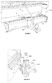
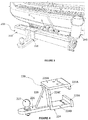
- Figures 1 to 3 illustrate the tow bar assembly 200 in an installed position whereby the tow-bar assembly 200 has been installed on a vehicle V.
- the tow-bar assembly 200 comprises a tubular elongate frame 210 which is attached to a tow-bar receiving socket (S) of the vehicle V such that the elongate frame 210 extends in lateral direction relative to a direction of motion of the vehicle V.
- the elongate frame 210 includes a connector 212 that is welded to an outer wall of the elongate frame 210 and extends in a generally perpendicular direction from the main body of the elongate frame 210.
- the connector 212 is provided in the form of a square shaped tube that is configured for being received into the socket S having a complementary configuration.
- the socket S may take the form of a conventional tow-bar socket which is typically coupled with the chassis of the vehicle V.
- a securing arrangement for securing the connector 212 within the socket S may also be provided to prevent the connector 212 (and the elongate frame 210) from inadvertently becoming uncoupled from the socket S during use.
- Substantially triangular gusset members 213 are also welded to the walls of the connector 212 and the rear wall of the elongate frame 210 for reinforcing the welded connection between the connector 212 and the elongate frame 210.
- the tow-bar assembly 200 also comprises a movable towing attachment 220 which is configured to slide along a length of the elongate frame 210.
- the towing attachment 220 comprises a C-shaped sleeve member 224 that is shaped to receive a section of the elongate frame in an internal space defined by the C-shaped member 224.
- the C shaped member 224 comprises spaced apart and mutually opposed plates 224A and 224B which are spaced apart and welded to a transversely arranged connecting plate 224C so that during use inner walls of the spaced apart plates 224A and 224B can be arranged adjacently relative to opposed outer walls of the elongate frame 210 in order to support the towing attachment 220 and allow the towing attachment 220 to translate over the length of the elongate frame 210.
- the spaced apart plates 224A and 224B include corresponding lip portions 223A and 223B that are provided in a mutually opposed configuration to prevent the towing attachment 220 from being detached from the elongate frame 210 when a towing force is applied in a transverse direction relative to the elongate frame 210.
- the towing attachment 220 also includes an outwardly extending tongue portion 226 that allows a tow ball 227 to be mounted thereon.
- a reinforcing member 229 extending between the tongue portion 227 and the transverse connecting plate 224C is provided for reinforcing the welded connection between the tongue 226 and the C-shaped sleeve member 224.
- the outwardly extending tongue portion 226 is welded onto the transverse connecting plate 224C to be substantially in alignment with one of said spaced apart plates 224A and 224B.
- Such a configuration of the towing attachment 220 allows the towing attachment to be inverted and positioned along the fixed elongate frame 210 in order to vary the height of the tongue portion (which supports the tow ball 227).
- the tongue portion 226 in a first in-use configuration, is positioned at a higher elevation relative to the supporting surface for the vehicle. In a second in-use configuration, the tongue portion 226 is positioned at a relatively lower elevation.
- the tongue portion 226 may be modified to allow the position of the tongue portion 226 to be movably adjusted along various mounting locations along the transverse connecting plate 224C without departing from the spirit and scope of the invention. It is important to note that after the towing attachment 220 is inverted, the towball 227 needs to be uncoupled from the tongue portion 226 (preferably by using a fastening nut of the towball) and re-positioned so that the towball 227 is mounted on the tongue portion 226 in an upwardly facing configuration.
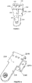
- the towing attachment 220 is removably fastened to a sliding block 260 (clearly visible in Figures 8 to 10 ) that is positioned within an internal cavity defined by the walls of the elongate frame 210.
- a sliding block 260 (clearly visible in Figures 8 to 10 ) that is positioned within an internal cavity defined by the walls of the elongate frame 210.
- the spaced apart plates 224A and 224B of the C-shaped member 224 are bolted onto the sliding block 260.
- the sliding block 260 is provided with bolt holes 262 that extend in a transverse direction relative to the elongate frame 210 and correspond with bolt holes 223 provided along each of the spaced apart plates 224A and 224B.
- Fastening bolts 228 are provided for fastening the towing attachment 220 with the sliding block 260 which in turn allows the towing attachment 220 to slide along the elongate frame 210 whilst being attached to the sliding block 260.
- the provision of the fastening bolts 228 also allows the bolts 228 to be removed in order to remove the towing attachment 220 relatively easily by sliding the towing attachment out of the elongate frame 210.
- the sliding block 260 that is positioned within the housing of the elongate frame 210 is driven by a drive motor 240.
- a top portion and a bottom portion of the sliding block 260 is accessible from an elongate slot 221 that is provided along a top and bottom wall of the elongate frame 210.
- the provision of the elongate slot along each of the top and bottom wall of the elongate frame 210 allows the spaced apart plates 224A and 224B to be fastened onto the top and bottom portions of the sliding block 260 and allows the towing attachment 220 to be fastened onto the sliding block 260.
- the sliding block 260 when bolted to the towing attachment 220, allows power to be transmitted from the drive motor to the towing attachment 220.
- a worm gear drive 245 (shown clearly in Figure 10 ) is coupled with the drive motor 240 for driving the sliding block 260 (which is fastened to the towing attachment 220).
- Hexagonal nuts 264 ( Figure 12 and 12A ) are provided for transferring drive from the worm gear drive 245 to the sliding block 260.
- the hexagonal head portion of the nuts 264 include an opening for threadedly receiving the worm gear drive 245 (best shown in Figures 12 and 12A ).
- the shank portion of the nut 264 is fastened onto a side wall of the sliding block 260 (shown clearly in Figure 12 ).
- any movement of the worm gear 245 results in translation of the sliding block 260 along the length of an elongate cavity defined by the walls of the elongate frame 210.
- the towing attachment 220 when fastened to the sliding block 260 also moves along a length of the elongate frame 210.
- the motor 240 may be controllable by, for instance, a controller mounted along the elongate frame 210 which may include conventional switches and/or buttons, as known by one of ordinary skill in the art.
- a plug receptacle could be replaced with a receiver of electromagnetic signals (not shown), and controller could be replaced with a remote control (not shown) that emits electromagnetic signals for controlling the motor 240.
- the towing assembly 200 also includes a bracket assembly provided within the elongate frame 210 for mounting the worm gear drive 245 within the internal space defined by the walls of the tubular elongate frame 210 such that the worm gear 245 extends between two lateral ends of the elongate frame 210.
- Plate guides and bearing plates 247 may be provided at either lateral end of the housing defined by the walls of the elongate frame 210 for supporting the worm gear 245.
- the plates and bearing for positioning the worm gear 245 may be used with any suitable fasteners, such as bolts, to permit disassembly and service of internal components, or may be permanently affixed within the elongate frame 210 via welding, etc., where disassembly is not required.
- a locking arrangement is also provided for optionally locking the position of the towing attachment 220 relative to the elongate frame 210 at a substantially central location relative to the elongate frame 210.
- two locking pins 292 (shown in Figure 7 ) are adapted to be received into respective locking apertures (shown in Figures 9 and 10 ) provided along an outer top wall of the elongate frame 210 and corresponding locking apertures 295 (shown in Figure 5 ) positioned along the spaced apart plate 224A (or 224B).
- the locking pins 292 are received in the respective locking apertures 293 and 295 provided in the elongate frame 220 and the attachment member 220 and prevent movement of the towing attachment 220 relative to the elongate frame 210.
- the configuration of the towing attachment 220 in combination with the elongate frame 210 in combination with the driving arrangement allows the towbar assembly to function like a normal tow bar during usual towing.
- the driving arrangement (including the drive motor 240 in combination with the worm gear 245 and the sliding block 260 fastened to the towing attachment 220) allows translational movement of the towing attachment 220 along a length of the elongate frame 210.
- the provision of the aforementioned configuration provides additional control over a towed vehicle during difficult manoeuvres, such as when reversing the vehicle V.
- the additional control over the towed vehicle improves safety by reducing the likelihood of the towed vehicle having a collision with either the environment or bystanders.
- the movable towbar assembly 200 further provides additional convenience and efficiency during difficult towing manoeuvres.
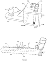
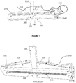
- Figure 13 illustrates a movable tow bar assembly 10, in accordance with a second embodiment, mounted to a vehicle 20 having a rear end 22 and two opposed sides 24.
- the movable tow bar assembly 10 has a frame 100 mounted to the rear of the vehicle 20 and an extension member 120 connected to the frame 100.
- the frame 100 is preferably rigidly affixed to a chassis of the vehicle 20 with a support plate 102 adjacent the extension member 120.
- a pair of support plates 102 are provided.
- the pair of support plates 102 are preferably aligned in spaced apart parallel planes with the extension member 120 being received between the two support plates 102.
- the extension member 120 has a towing attachment, in the form of a tow ball 122, at an end that is distal from the vehicle 20.
- the extension member 120 is connected to the frame 100 by a pivot pin 124.
- the extension member 120 also has a locking assembly in the form of a removable locking pin 126 the also connects the extension member 120 to the frame 100.
- the pivot pin 124 and locking pin 126 are both receivable in respective apertures in the frame 100 and the extension member 120.
- the extension member 120 is also coupled to an actuator in the form of a hydraulic cylinder 140.
- the hydraulic cylinder 140 is connected substantially perpendicularly to a longitudinal axis of the extension member 120 such that extension and retraction of the hydraulic cylinder 140 causes the extension member to pivot around the pivot pin 124 when the locking assembly is unlocked, e.g. when the locking pin 126 is removed from the extension member 120 and/or frame 100.
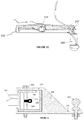
- Figure 14 illustrates an alternative embodiment of a movable tow bar 10 wherein the tow ball 122 is movable within a rail in the form of a channel 104 in the frame 100.
- the channel 104 is substantially linear with a longitudinal axis substantially perpendicular to a towing axis.
- the actuator (not shown in Figure14 ) for this arrangement preferably includes an electric motor and gearbox. A worm drive may also be utilised.
- a straight channel 104 is illustrated in Figure 14 it will be appreciated that the channel could take other forms such as, for example, a curved channel.
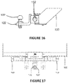
- Figures 15 to 17 illustrate an alternative embodiment of a movable tow bar assembly 10 wherein the tow ball 122 is located on a sleeve 150 via bracket 122'.
- the sleeve 150 is slidably mounted to a rail 160.
- the rail 160 is substantially cylindrical, with the sleeve 150 having a correspondingly shaped substantially cylindrical opening of channel running therethrough.
- the rail 160 is contained between two end stops 162.
- the sleeve 150 can slide along the rail between the end stops 162 as illustrated in Figure 17 .
- the sleeve is connected to one end of a concealed hydraulic cylinder (not shown) and the rail is connected to another end of the hydraulic cylinder.
- hydraulic ports 152 are provided to control the hydraulic cylinder.
- the hydraulic ports 152 can be utilised to connect the hydraulic cylinder to a hydraulic reservoir and pump.
- the reservoir and pump (not shown) are contained inside the frame 100.
- the movable tow bar assembly 10 of Figure 13 may be used like a normal tow bar with the extension member 120 locked such that its longitudinal axis substantially coincides with the longitudinal axis of the vehicle 20.
- additional manoeuvrability such as when reversing the vehicle 20 with a towed vehicle such as a trailer attached to the tow ball 122, additional control over the towed vehicle may be obtained by removing the locking pin 126 and actuating the hydraulic cylinder 140.
- the hydraulic cylinder 140 is preferably controlled from a cabin of the vehicle 20, to enable a user to pivot the extension member 120 with tow-ball 122 thereon towards either the left or right side of the vehicle.
- the pivot movement will also bring the tow ball 122 closer to a rear of the vehicle 20.
- the angle between the vehicle 20 and the towed vehicle is altered. This change in angle can be used to the driver's advantage to direct the towed vehicle in a particular direction to achieve a desired path for the towed vehicle to travel.
- the movable tow bar assembly 10 of Figure 14 is operated in a similar manner, with the tow ball 122 being movable with respect to the frame 100 and hence the vehicle 20. As the tow ball 122 is moved in the channel 104, the angle between the vehicle 20 and the towed vehicle is altered and, again, can be used to the driver's advantage to direct the towed vehicle in a particular direction to achieve a desired path for the towed vehicle to travel.
- the movable tow bar assembly 10 of figures 15 to 17 is operated in a similar manner, with the tow ball 122 being movable with respect to the frame 100 and hence the vehicle 20 by sliding the sleeve 150 across the rail 160. As a controller is operated, manually or automatically, the hydraulic cylinder slides the sleeve 150 longitudinally along the rail 160 to move the tow ball 122 towards a side of the vehicle to which the movable tow bar 10 is mounted.
- the movable tow bar assembly 10 operates like a normal tow bar during usual towing, but allows the tow ball 122 of the tow bar 10 to be moved when desired.
- This provides additional control over a towed vehicle during difficult manoeuvres, such as when reversing the vehicle 20.
- the additional control over the towed vehicle can vastly improve safety by reducing the likelihood of the towed vehicle having a collision with either the environment or bystanders.
- the movable towbar assembly 10 further provides additional convenience and efficiency during difficult towing manoeuvres.
- the terms 'comprises', 'comprising', 'includes', 'including', or similar terms are intended to mean a non-exclusive inclusion, such that a method, system or apparatus that comprises a list of elements does not include those elements solely, but may well include other elements not listed.
Landscapes
- Engineering & Computer Science (AREA)
- Transportation (AREA)
- Mechanical Engineering (AREA)
- Body Structure For Vehicles (AREA)
Applications Claiming Priority (1)
| Application Number | Priority Date | Filing Date | Title |
|---|---|---|---|
| NZ17731643 | 2017-05-05 |
Publications (3)
| Publication Number | Publication Date |
|---|---|
| EP3441242A2 true EP3441242A2 (de) | 2019-02-13 |
| EP3441242A3 EP3441242A3 (de) | 2019-02-20 |
| EP3441242B1 EP3441242B1 (de) | 2021-11-17 |
Family
ID=62089628
Family Applications (1)
| Application Number | Title | Priority Date | Filing Date |
|---|---|---|---|
| EP18169831.7A Active EP3441242B1 (de) | 2017-05-05 | 2018-04-27 | Bewegliche schleppstangenanordnung |
Country Status (1)
| Country | Link |
|---|---|
| EP (1) | EP3441242B1 (de) |
Family Cites Families (3)
| Publication number | Priority date | Publication date | Assignee | Title |
|---|---|---|---|---|
| US3178203A (en) * | 1962-08-29 | 1965-04-13 | Bernard E Elliott | Tandem trailer steering mechanism |
| US8091913B1 (en) * | 2010-04-06 | 2012-01-10 | White Donald M | Variable adjustable trailer hitch |
| WO2016070245A1 (en) * | 2014-11-07 | 2016-05-12 | Tiainen Richard | Movable tow bar |
-
2018
- 2018-04-27 EP EP18169831.7A patent/EP3441242B1/de active Active
Non-Patent Citations (1)
| Title |
|---|
| None |
Also Published As
| Publication number | Publication date |
|---|---|
| EP3441242A3 (de) | 2019-02-20 |
| EP3441242B1 (de) | 2021-11-17 |
Similar Documents
| Publication | Publication Date | Title |
|---|---|---|
| US10308086B2 (en) | Movable tow bar assembly | |
| EP2417007B1 (de) | Automatisches pneumatisch-elektrisches kopplersystem für traktor/anhänger-kombinationsfahrzeuge | |
| US6363629B1 (en) | Vehicle hitch mount assembly for a snow plow | |
| US8678421B1 (en) | Articulating hitch apparatus for vehicles | |
| US7806423B2 (en) | Fifth wheel assembly for coupling a trailer to a truck tractor and a method for operating said assembly | |
| US5346239A (en) | Tractor train, optionally an articulated train | |
| US20050103541A1 (en) | Mobile trailer hitching apparatus | |
| US9764778B2 (en) | Coupling part | |
| CA2591549C (en) | System for connecting of supply lines | |
| EP1886845B1 (de) | Anhängerkupplung für Zugfahrzeuge, insbesondere für landwirtschaftliche Traktoren | |
| EP3441242B1 (de) | Bewegliche schleppstangenanordnung | |
| US20220234403A1 (en) | Trailer Hitch System Including Actuatable Multi-Directional Trailer Hitch and Method | |
| AU2017202996B2 (en) | Movable tow bar assembly | |
| CA2966257C (en) | Movable tow bar assembly | |
| NZ731643A (en) | Movable tow bar assembly | |
| EP2643175B1 (de) | Befestigungsvorrichtung für eine anhängerdeichsel | |
| EP0308271B1 (de) | Zugstangenvorrichtung | |
| US7568717B2 (en) | Tow coupling system and method | |
| EP0425462A2 (de) | Anhängerkupplung | |
| US1500236A (en) | Industrial truck | |
| EP4387578B1 (de) | Andocksystem für rollstühle | |
| KR200191050Y1 (ko) | 토우 트럭 장착용 제설 삽날 조립체 | |
| NZ731643B2 (en) | Movable tow bar assembly | |
| KR200191719Y1 (ko) | 토우 트럭용 견인 고리 조립체 | |
| KR20000014965A (ko) | 토우 트럭용 견인 고리 조립체 |
Legal Events
| Date | Code | Title | Description |
|---|---|---|---|
| PUAI | Public reference made under article 153(3) epc to a published international application that has entered the european phase |
Free format text: ORIGINAL CODE: 0009012 |
|
| STAA | Information on the status of an ep patent application or granted ep patent |
Free format text: STATUS: THE APPLICATION HAS BEEN PUBLISHED |
|
| PUAL | Search report despatched |
Free format text: ORIGINAL CODE: 0009013 |
|
| AK | Designated contracting states |
Kind code of ref document: A2 Designated state(s): AL AT BE BG CH CY CZ DE DK EE ES FI FR GB GR HR HU IE IS IT LI LT LU LV MC MK MT NL NO PL PT RO RS SE SI SK SM TR |
|
| AX | Request for extension of the european patent |
Extension state: BA ME |
|
| AK | Designated contracting states |
Kind code of ref document: A3 Designated state(s): AL AT BE BG CH CY CZ DE DK EE ES FI FR GB GR HR HU IE IS IT LI LT LU LV MC MK MT NL NO PL PT RO RS SE SI SK SM TR |
|
| AX | Request for extension of the european patent |
Extension state: BA ME |
|
| RIC1 | Information provided on ipc code assigned before grant |
Ipc: B60D 1/62 20060101ALI20190117BHEP Ipc: B60D 1/24 20060101ALI20190117BHEP Ipc: B60D 1/06 20060101AFI20190117BHEP Ipc: B60D 1/44 20060101ALI20190117BHEP |
|
| STAA | Information on the status of an ep patent application or granted ep patent |
Free format text: STATUS: REQUEST FOR EXAMINATION WAS MADE |
|
| 17P | Request for examination filed |
Effective date: 20190820 |
|
| RBV | Designated contracting states (corrected) |
Designated state(s): AL AT BE BG CH CY CZ DE DK EE ES FI FR GB GR HR HU IE IS IT LI LT LU LV MC MK MT NL NO PL PT RO RS SE SI SK SM TR |
|
| STAA | Information on the status of an ep patent application or granted ep patent |
Free format text: STATUS: EXAMINATION IS IN PROGRESS |
|
| 17Q | First examination report despatched |
Effective date: 20201215 |
|
| GRAP | Despatch of communication of intention to grant a patent |
Free format text: ORIGINAL CODE: EPIDOSNIGR1 |
|
| STAA | Information on the status of an ep patent application or granted ep patent |
Free format text: STATUS: GRANT OF PATENT IS INTENDED |
|
| INTG | Intention to grant announced |
Effective date: 20210604 |
|
| GRAS | Grant fee paid |
Free format text: ORIGINAL CODE: EPIDOSNIGR3 |
|
| GRAA | (expected) grant |
Free format text: ORIGINAL CODE: 0009210 |
|
| STAA | Information on the status of an ep patent application or granted ep patent |
Free format text: STATUS: THE PATENT HAS BEEN GRANTED |
|
| AK | Designated contracting states |
Kind code of ref document: B1 Designated state(s): AL AT BE BG CH CY CZ DE DK EE ES FI FR GB GR HR HU IE IS IT LI LT LU LV MC MK MT NL NO PL PT RO RS SE SI SK SM TR |
|
| REG | Reference to a national code |
Ref country code: GB Ref legal event code: FG4D |
|
| REG | Reference to a national code |
Ref country code: DE Ref legal event code: R096 Ref document number: 602018026705 Country of ref document: DE |
|
| REG | Reference to a national code |
Ref country code: IE Ref legal event code: FG4D |
|
| REG | Reference to a national code |
Ref country code: AT Ref legal event code: REF Ref document number: 1447750 Country of ref document: AT Kind code of ref document: T Effective date: 20211215 |
|
| REG | Reference to a national code |
Ref country code: LT Ref legal event code: MG9D |
|
| REG | Reference to a national code |
Ref country code: NL Ref legal event code: MP Effective date: 20211117 |
|
| REG | Reference to a national code |
Ref country code: AT Ref legal event code: MK05 Ref document number: 1447750 Country of ref document: AT Kind code of ref document: T Effective date: 20211117 |
|
| PG25 | Lapsed in a contracting state [announced via postgrant information from national office to epo] |
Ref country code: RS Free format text: LAPSE BECAUSE OF FAILURE TO SUBMIT A TRANSLATION OF THE DESCRIPTION OR TO PAY THE FEE WITHIN THE PRESCRIBED TIME-LIMIT Effective date: 20211117 Ref country code: LT Free format text: LAPSE BECAUSE OF FAILURE TO SUBMIT A TRANSLATION OF THE DESCRIPTION OR TO PAY THE FEE WITHIN THE PRESCRIBED TIME-LIMIT Effective date: 20211117 Ref country code: FI Free format text: LAPSE BECAUSE OF FAILURE TO SUBMIT A TRANSLATION OF THE DESCRIPTION OR TO PAY THE FEE WITHIN THE PRESCRIBED TIME-LIMIT Effective date: 20211117 Ref country code: BG Free format text: LAPSE BECAUSE OF FAILURE TO SUBMIT A TRANSLATION OF THE DESCRIPTION OR TO PAY THE FEE WITHIN THE PRESCRIBED TIME-LIMIT Effective date: 20220217 Ref country code: AT Free format text: LAPSE BECAUSE OF FAILURE TO SUBMIT A TRANSLATION OF THE DESCRIPTION OR TO PAY THE FEE WITHIN THE PRESCRIBED TIME-LIMIT Effective date: 20211117 |
|
| PG25 | Lapsed in a contracting state [announced via postgrant information from national office to epo] |
Ref country code: IS Free format text: LAPSE BECAUSE OF FAILURE TO SUBMIT A TRANSLATION OF THE DESCRIPTION OR TO PAY THE FEE WITHIN THE PRESCRIBED TIME-LIMIT Effective date: 20220317 Ref country code: SE Free format text: LAPSE BECAUSE OF FAILURE TO SUBMIT A TRANSLATION OF THE DESCRIPTION OR TO PAY THE FEE WITHIN THE PRESCRIBED TIME-LIMIT Effective date: 20211117 Ref country code: PT Free format text: LAPSE BECAUSE OF FAILURE TO SUBMIT A TRANSLATION OF THE DESCRIPTION OR TO PAY THE FEE WITHIN THE PRESCRIBED TIME-LIMIT Effective date: 20220317 Ref country code: PL Free format text: LAPSE BECAUSE OF FAILURE TO SUBMIT A TRANSLATION OF THE DESCRIPTION OR TO PAY THE FEE WITHIN THE PRESCRIBED TIME-LIMIT Effective date: 20211117 Ref country code: NO Free format text: LAPSE BECAUSE OF FAILURE TO SUBMIT A TRANSLATION OF THE DESCRIPTION OR TO PAY THE FEE WITHIN THE PRESCRIBED TIME-LIMIT Effective date: 20220217 Ref country code: NL Free format text: LAPSE BECAUSE OF FAILURE TO SUBMIT A TRANSLATION OF THE DESCRIPTION OR TO PAY THE FEE WITHIN THE PRESCRIBED TIME-LIMIT Effective date: 20211117 Ref country code: LV Free format text: LAPSE BECAUSE OF FAILURE TO SUBMIT A TRANSLATION OF THE DESCRIPTION OR TO PAY THE FEE WITHIN THE PRESCRIBED TIME-LIMIT Effective date: 20211117 Ref country code: HR Free format text: LAPSE BECAUSE OF FAILURE TO SUBMIT A TRANSLATION OF THE DESCRIPTION OR TO PAY THE FEE WITHIN THE PRESCRIBED TIME-LIMIT Effective date: 20211117 Ref country code: GR Free format text: LAPSE BECAUSE OF FAILURE TO SUBMIT A TRANSLATION OF THE DESCRIPTION OR TO PAY THE FEE WITHIN THE PRESCRIBED TIME-LIMIT Effective date: 20220218 Ref country code: ES Free format text: LAPSE BECAUSE OF FAILURE TO SUBMIT A TRANSLATION OF THE DESCRIPTION OR TO PAY THE FEE WITHIN THE PRESCRIBED TIME-LIMIT Effective date: 20211117 |
|
| PG25 | Lapsed in a contracting state [announced via postgrant information from national office to epo] |
Ref country code: SM Free format text: LAPSE BECAUSE OF FAILURE TO SUBMIT A TRANSLATION OF THE DESCRIPTION OR TO PAY THE FEE WITHIN THE PRESCRIBED TIME-LIMIT Effective date: 20211117 Ref country code: SK Free format text: LAPSE BECAUSE OF FAILURE TO SUBMIT A TRANSLATION OF THE DESCRIPTION OR TO PAY THE FEE WITHIN THE PRESCRIBED TIME-LIMIT Effective date: 20211117 Ref country code: RO Free format text: LAPSE BECAUSE OF FAILURE TO SUBMIT A TRANSLATION OF THE DESCRIPTION OR TO PAY THE FEE WITHIN THE PRESCRIBED TIME-LIMIT Effective date: 20211117 Ref country code: EE Free format text: LAPSE BECAUSE OF FAILURE TO SUBMIT A TRANSLATION OF THE DESCRIPTION OR TO PAY THE FEE WITHIN THE PRESCRIBED TIME-LIMIT Effective date: 20211117 Ref country code: DK Free format text: LAPSE BECAUSE OF FAILURE TO SUBMIT A TRANSLATION OF THE DESCRIPTION OR TO PAY THE FEE WITHIN THE PRESCRIBED TIME-LIMIT Effective date: 20211117 Ref country code: CZ Free format text: LAPSE BECAUSE OF FAILURE TO SUBMIT A TRANSLATION OF THE DESCRIPTION OR TO PAY THE FEE WITHIN THE PRESCRIBED TIME-LIMIT Effective date: 20211117 |
|
| REG | Reference to a national code |
Ref country code: DE Ref legal event code: R097 Ref document number: 602018026705 Country of ref document: DE |
|
| PLBE | No opposition filed within time limit |
Free format text: ORIGINAL CODE: 0009261 |
|
| STAA | Information on the status of an ep patent application or granted ep patent |
Free format text: STATUS: NO OPPOSITION FILED WITHIN TIME LIMIT |
|
| 26N | No opposition filed |
Effective date: 20220818 |
|
| PG25 | Lapsed in a contracting state [announced via postgrant information from national office to epo] |
Ref country code: AL Free format text: LAPSE BECAUSE OF FAILURE TO SUBMIT A TRANSLATION OF THE DESCRIPTION OR TO PAY THE FEE WITHIN THE PRESCRIBED TIME-LIMIT Effective date: 20211117 |
|
| PG25 | Lapsed in a contracting state [announced via postgrant information from national office to epo] |
Ref country code: SI Free format text: LAPSE BECAUSE OF FAILURE TO SUBMIT A TRANSLATION OF THE DESCRIPTION OR TO PAY THE FEE WITHIN THE PRESCRIBED TIME-LIMIT Effective date: 20211117 |
|
| REG | Reference to a national code |
Ref country code: CH Ref legal event code: PL |
|
| REG | Reference to a national code |
Ref country code: BE Ref legal event code: MM Effective date: 20220430 |
|
| PG25 | Lapsed in a contracting state [announced via postgrant information from national office to epo] |
Ref country code: MC Free format text: LAPSE BECAUSE OF FAILURE TO SUBMIT A TRANSLATION OF THE DESCRIPTION OR TO PAY THE FEE WITHIN THE PRESCRIBED TIME-LIMIT Effective date: 20211117 Ref country code: LU Free format text: LAPSE BECAUSE OF NON-PAYMENT OF DUE FEES Effective date: 20220427 Ref country code: LI Free format text: LAPSE BECAUSE OF NON-PAYMENT OF DUE FEES Effective date: 20220430 Ref country code: CH Free format text: LAPSE BECAUSE OF NON-PAYMENT OF DUE FEES Effective date: 20220430 |
|
| PG25 | Lapsed in a contracting state [announced via postgrant information from national office to epo] |
Ref country code: BE Free format text: LAPSE BECAUSE OF NON-PAYMENT OF DUE FEES Effective date: 20220430 |
|
| PG25 | Lapsed in a contracting state [announced via postgrant information from national office to epo] |
Ref country code: IE Free format text: LAPSE BECAUSE OF NON-PAYMENT OF DUE FEES Effective date: 20220427 |
|
| PG25 | Lapsed in a contracting state [announced via postgrant information from national office to epo] |
Ref country code: IT Free format text: LAPSE BECAUSE OF FAILURE TO SUBMIT A TRANSLATION OF THE DESCRIPTION OR TO PAY THE FEE WITHIN THE PRESCRIBED TIME-LIMIT Effective date: 20211117 |
|
| PG25 | Lapsed in a contracting state [announced via postgrant information from national office to epo] |
Ref country code: HU Free format text: LAPSE BECAUSE OF FAILURE TO SUBMIT A TRANSLATION OF THE DESCRIPTION OR TO PAY THE FEE WITHIN THE PRESCRIBED TIME-LIMIT; INVALID AB INITIO Effective date: 20180427 |
|
| PG25 | Lapsed in a contracting state [announced via postgrant information from national office to epo] |
Ref country code: MK Free format text: LAPSE BECAUSE OF FAILURE TO SUBMIT A TRANSLATION OF THE DESCRIPTION OR TO PAY THE FEE WITHIN THE PRESCRIBED TIME-LIMIT Effective date: 20211117 Ref country code: CY Free format text: LAPSE BECAUSE OF FAILURE TO SUBMIT A TRANSLATION OF THE DESCRIPTION OR TO PAY THE FEE WITHIN THE PRESCRIBED TIME-LIMIT Effective date: 20211117 |
|
| PG25 | Lapsed in a contracting state [announced via postgrant information from national office to epo] |
Ref country code: MT Free format text: LAPSE BECAUSE OF FAILURE TO SUBMIT A TRANSLATION OF THE DESCRIPTION OR TO PAY THE FEE WITHIN THE PRESCRIBED TIME-LIMIT Effective date: 20211117 |
|
| PGFP | Annual fee paid to national office [announced via postgrant information from national office to epo] |
Ref country code: DE Payment date: 20250420 Year of fee payment: 8 |
|
| PGFP | Annual fee paid to national office [announced via postgrant information from national office to epo] |
Ref country code: GB Payment date: 20250406 Year of fee payment: 8 |
|
| PGFP | Annual fee paid to national office [announced via postgrant information from national office to epo] |
Ref country code: FR Payment date: 20250420 Year of fee payment: 8 |
|
| PG25 | Lapsed in a contracting state [announced via postgrant information from national office to epo] |
Ref country code: TR Free format text: LAPSE BECAUSE OF FAILURE TO SUBMIT A TRANSLATION OF THE DESCRIPTION OR TO PAY THE FEE WITHIN THE PRESCRIBED TIME-LIMIT Effective date: 20211117 |