EP3441219A1 - Resin structure - Google Patents
Resin structure Download PDFInfo
- Publication number
- EP3441219A1 EP3441219A1 EP18187298.7A EP18187298A EP3441219A1 EP 3441219 A1 EP3441219 A1 EP 3441219A1 EP 18187298 A EP18187298 A EP 18187298A EP 3441219 A1 EP3441219 A1 EP 3441219A1
- Authority
- EP
- European Patent Office
- Prior art keywords
- fibers
- structural portion
- pattern
- design surface
- structural
- Prior art date
- Legal status (The legal status is an assumption and is not a legal conclusion. Google has not performed a legal analysis and makes no representation as to the accuracy of the status listed.)
- Granted
Links
Images


Classifications
-
- B—PERFORMING OPERATIONS; TRANSPORTING
- B62—LAND VEHICLES FOR TRAVELLING OTHERWISE THAN ON RAILS
- B62D—MOTOR VEHICLES; TRAILERS
- B62D35/00—Vehicle bodies characterised by streamlining
- B62D35/007—Rear spoilers
-
- B—PERFORMING OPERATIONS; TRANSPORTING
- B32—LAYERED PRODUCTS
- B32B—LAYERED PRODUCTS, i.e. PRODUCTS BUILT-UP OF STRATA OF FLAT OR NON-FLAT, e.g. CELLULAR OR HONEYCOMB, FORM
- B32B5/00—Layered products characterised by the non- homogeneity or physical structure, i.e. comprising a fibrous, filamentary, particulate or foam layer; Layered products characterised by having a layer differing constitutionally or physically in different parts
- B32B5/02—Layered products characterised by the non- homogeneity or physical structure, i.e. comprising a fibrous, filamentary, particulate or foam layer; Layered products characterised by having a layer differing constitutionally or physically in different parts characterised by structural features of a fibrous or filamentary layer
- B32B5/12—Layered products characterised by the non- homogeneity or physical structure, i.e. comprising a fibrous, filamentary, particulate or foam layer; Layered products characterised by having a layer differing constitutionally or physically in different parts characterised by structural features of a fibrous or filamentary layer characterised by the relative arrangement of fibres or filaments of different layers, e.g. the fibres or filaments being parallel or perpendicular to each other
-
- B—PERFORMING OPERATIONS; TRANSPORTING
- B29—WORKING OF PLASTICS; WORKING OF SUBSTANCES IN A PLASTIC STATE IN GENERAL
- B29C—SHAPING OR JOINING OF PLASTICS; SHAPING OF MATERIAL IN A PLASTIC STATE, NOT OTHERWISE PROVIDED FOR; AFTER-TREATMENT OF THE SHAPED PRODUCTS, e.g. REPAIRING
- B29C70/00—Shaping composites, i.e. plastics material comprising reinforcements, fillers or preformed parts, e.g. inserts
- B29C70/04—Shaping composites, i.e. plastics material comprising reinforcements, fillers or preformed parts, e.g. inserts comprising reinforcements only, e.g. self-reinforcing plastics
- B29C70/06—Fibrous reinforcements only
- B29C70/10—Fibrous reinforcements only characterised by the structure of fibrous reinforcements, e.g. hollow fibres
- B29C70/16—Fibrous reinforcements only characterised by the structure of fibrous reinforcements, e.g. hollow fibres using fibres of substantial or continuous length
- B29C70/22—Fibrous reinforcements only characterised by the structure of fibrous reinforcements, e.g. hollow fibres using fibres of substantial or continuous length oriented in at least two directions forming a two-dimensional [2D] structure
- B29C70/222—Fibrous reinforcements only characterised by the structure of fibrous reinforcements, e.g. hollow fibres using fibres of substantial or continuous length oriented in at least two directions forming a two-dimensional [2D] structure the structure being shaped to form a three dimensional configuration
-
- B—PERFORMING OPERATIONS; TRANSPORTING
- B29—WORKING OF PLASTICS; WORKING OF SUBSTANCES IN A PLASTIC STATE IN GENERAL
- B29C—SHAPING OR JOINING OF PLASTICS; SHAPING OF MATERIAL IN A PLASTIC STATE, NOT OTHERWISE PROVIDED FOR; AFTER-TREATMENT OF THE SHAPED PRODUCTS, e.g. REPAIRING
- B29C70/00—Shaping composites, i.e. plastics material comprising reinforcements, fillers or preformed parts, e.g. inserts
- B29C70/04—Shaping composites, i.e. plastics material comprising reinforcements, fillers or preformed parts, e.g. inserts comprising reinforcements only, e.g. self-reinforcing plastics
- B29C70/28—Shaping operations therefor
- B29C70/40—Shaping or impregnating by compression not applied
- B29C70/42—Shaping or impregnating by compression not applied for producing articles of definite length, i.e. discrete articles
- B29C70/44—Shaping or impregnating by compression not applied for producing articles of definite length, i.e. discrete articles using isostatic pressure, e.g. pressure difference-moulding, vacuum bag-moulding, autoclave-moulding or expanding rubber-moulding
- B29C70/443—Shaping or impregnating by compression not applied for producing articles of definite length, i.e. discrete articles using isostatic pressure, e.g. pressure difference-moulding, vacuum bag-moulding, autoclave-moulding or expanding rubber-moulding and impregnating by vacuum or injection
-
- B—PERFORMING OPERATIONS; TRANSPORTING
- B29—WORKING OF PLASTICS; WORKING OF SUBSTANCES IN A PLASTIC STATE IN GENERAL
- B29C—SHAPING OR JOINING OF PLASTICS; SHAPING OF MATERIAL IN A PLASTIC STATE, NOT OTHERWISE PROVIDED FOR; AFTER-TREATMENT OF THE SHAPED PRODUCTS, e.g. REPAIRING
- B29C70/00—Shaping composites, i.e. plastics material comprising reinforcements, fillers or preformed parts, e.g. inserts
- B29C70/04—Shaping composites, i.e. plastics material comprising reinforcements, fillers or preformed parts, e.g. inserts comprising reinforcements only, e.g. self-reinforcing plastics
- B29C70/28—Shaping operations therefor
- B29C70/54—Component parts, details or accessories; Auxiliary operations, e.g. feeding or storage of prepregs or SMC after impregnation or during ageing
- B29C70/545—Perforating, cutting or machining during or after moulding
-
- B—PERFORMING OPERATIONS; TRANSPORTING
- B32—LAYERED PRODUCTS
- B32B—LAYERED PRODUCTS, i.e. PRODUCTS BUILT-UP OF STRATA OF FLAT OR NON-FLAT, e.g. CELLULAR OR HONEYCOMB, FORM
- B32B3/00—Layered products comprising a layer with external or internal discontinuities or unevennesses, or a layer of non-planar shape; Layered products comprising a layer having particular features of form
- B32B3/10—Layered products comprising a layer with external or internal discontinuities or unevennesses, or a layer of non-planar shape; Layered products comprising a layer having particular features of form characterised by a discontinuous layer, i.e. formed of separate pieces of material
- B32B3/14—Layered products comprising a layer with external or internal discontinuities or unevennesses, or a layer of non-planar shape; Layered products comprising a layer having particular features of form characterised by a discontinuous layer, i.e. formed of separate pieces of material characterised by a face layer formed of separate pieces of material which are juxtaposed side-by-side
-
- B—PERFORMING OPERATIONS; TRANSPORTING
- B32—LAYERED PRODUCTS
- B32B—LAYERED PRODUCTS, i.e. PRODUCTS BUILT-UP OF STRATA OF FLAT OR NON-FLAT, e.g. CELLULAR OR HONEYCOMB, FORM
- B32B5/00—Layered products characterised by the non- homogeneity or physical structure, i.e. comprising a fibrous, filamentary, particulate or foam layer; Layered products characterised by having a layer differing constitutionally or physically in different parts
- B32B5/02—Layered products characterised by the non- homogeneity or physical structure, i.e. comprising a fibrous, filamentary, particulate or foam layer; Layered products characterised by having a layer differing constitutionally or physically in different parts characterised by structural features of a fibrous or filamentary layer
- B32B5/026—Knitted fabric
-
- B—PERFORMING OPERATIONS; TRANSPORTING
- B32—LAYERED PRODUCTS
- B32B—LAYERED PRODUCTS, i.e. PRODUCTS BUILT-UP OF STRATA OF FLAT OR NON-FLAT, e.g. CELLULAR OR HONEYCOMB, FORM
- B32B5/00—Layered products characterised by the non- homogeneity or physical structure, i.e. comprising a fibrous, filamentary, particulate or foam layer; Layered products characterised by having a layer differing constitutionally or physically in different parts
- B32B5/22—Layered products characterised by the non- homogeneity or physical structure, i.e. comprising a fibrous, filamentary, particulate or foam layer; Layered products characterised by having a layer differing constitutionally or physically in different parts characterised by the presence of two or more layers which are next to each other and are fibrous, filamentary, formed of particles or foamed
- B32B5/24—Layered products characterised by the non- homogeneity or physical structure, i.e. comprising a fibrous, filamentary, particulate or foam layer; Layered products characterised by having a layer differing constitutionally or physically in different parts characterised by the presence of two or more layers which are next to each other and are fibrous, filamentary, formed of particles or foamed one layer being a fibrous or filamentary layer
- B32B5/245—Layered products characterised by the non- homogeneity or physical structure, i.e. comprising a fibrous, filamentary, particulate or foam layer; Layered products characterised by having a layer differing constitutionally or physically in different parts characterised by the presence of two or more layers which are next to each other and are fibrous, filamentary, formed of particles or foamed one layer being a fibrous or filamentary layer another layer next to it being a foam layer
-
- B—PERFORMING OPERATIONS; TRANSPORTING
- B32—LAYERED PRODUCTS
- B32B—LAYERED PRODUCTS, i.e. PRODUCTS BUILT-UP OF STRATA OF FLAT OR NON-FLAT, e.g. CELLULAR OR HONEYCOMB, FORM
- B32B5/00—Layered products characterised by the non- homogeneity or physical structure, i.e. comprising a fibrous, filamentary, particulate or foam layer; Layered products characterised by having a layer differing constitutionally or physically in different parts
- B32B5/22—Layered products characterised by the non- homogeneity or physical structure, i.e. comprising a fibrous, filamentary, particulate or foam layer; Layered products characterised by having a layer differing constitutionally or physically in different parts characterised by the presence of two or more layers which are next to each other and are fibrous, filamentary, formed of particles or foamed
- B32B5/24—Layered products characterised by the non- homogeneity or physical structure, i.e. comprising a fibrous, filamentary, particulate or foam layer; Layered products characterised by having a layer differing constitutionally or physically in different parts characterised by the presence of two or more layers which are next to each other and are fibrous, filamentary, formed of particles or foamed one layer being a fibrous or filamentary layer
- B32B5/28—Layered products characterised by the non- homogeneity or physical structure, i.e. comprising a fibrous, filamentary, particulate or foam layer; Layered products characterised by having a layer differing constitutionally or physically in different parts characterised by the presence of two or more layers which are next to each other and are fibrous, filamentary, formed of particles or foamed one layer being a fibrous or filamentary layer impregnated with or embedded in a plastic substance
-
- B—PERFORMING OPERATIONS; TRANSPORTING
- B29—WORKING OF PLASTICS; WORKING OF SUBSTANCES IN A PLASTIC STATE IN GENERAL
- B29K—INDEXING SCHEME ASSOCIATED WITH SUBCLASSES B29B, B29C OR B29D, RELATING TO MOULDING MATERIALS OR TO MATERIALS FOR MOULDS, REINFORCEMENTS, FILLERS OR PREFORMED PARTS, e.g. INSERTS
- B29K2105/00—Condition, form or state of moulded material or of the material to be shaped
- B29K2105/06—Condition, form or state of moulded material or of the material to be shaped containing reinforcements, fillers or inserts
- B29K2105/08—Condition, form or state of moulded material or of the material to be shaped containing reinforcements, fillers or inserts of continuous length, e.g. cords, rovings, mats, fabrics, strands or yarns
- B29K2105/0809—Fabrics
- B29K2105/0836—Knitted fabrics
-
- B—PERFORMING OPERATIONS; TRANSPORTING
- B29—WORKING OF PLASTICS; WORKING OF SUBSTANCES IN A PLASTIC STATE IN GENERAL
- B29K—INDEXING SCHEME ASSOCIATED WITH SUBCLASSES B29B, B29C OR B29D, RELATING TO MOULDING MATERIALS OR TO MATERIALS FOR MOULDS, REINFORCEMENTS, FILLERS OR PREFORMED PARTS, e.g. INSERTS
- B29K2105/00—Condition, form or state of moulded material or of the material to be shaped
- B29K2105/06—Condition, form or state of moulded material or of the material to be shaped containing reinforcements, fillers or inserts
- B29K2105/08—Condition, form or state of moulded material or of the material to be shaped containing reinforcements, fillers or inserts of continuous length, e.g. cords, rovings, mats, fabrics, strands or yarns
- B29K2105/0872—Prepregs
- B29K2105/089—Prepregs fabric
-
- B—PERFORMING OPERATIONS; TRANSPORTING
- B29—WORKING OF PLASTICS; WORKING OF SUBSTANCES IN A PLASTIC STATE IN GENERAL
- B29K—INDEXING SCHEME ASSOCIATED WITH SUBCLASSES B29B, B29C OR B29D, RELATING TO MOULDING MATERIALS OR TO MATERIALS FOR MOULDS, REINFORCEMENTS, FILLERS OR PREFORMED PARTS, e.g. INSERTS
- B29K2307/00—Use of elements other than metals as reinforcement
- B29K2307/04—Carbon
-
- B—PERFORMING OPERATIONS; TRANSPORTING
- B29—WORKING OF PLASTICS; WORKING OF SUBSTANCES IN A PLASTIC STATE IN GENERAL
- B29L—INDEXING SCHEME ASSOCIATED WITH SUBCLASS B29C, RELATING TO PARTICULAR ARTICLES
- B29L2031/00—Other particular articles
- B29L2031/30—Vehicles, e.g. ships or aircraft, or body parts thereof
- B29L2031/3055—Cars
- B29L2031/3058—Spoilers
-
- B—PERFORMING OPERATIONS; TRANSPORTING
- B32—LAYERED PRODUCTS
- B32B—LAYERED PRODUCTS, i.e. PRODUCTS BUILT-UP OF STRATA OF FLAT OR NON-FLAT, e.g. CELLULAR OR HONEYCOMB, FORM
- B32B2250/00—Layers arrangement
- B32B2250/44—Number of layers variable across the laminate
-
- B—PERFORMING OPERATIONS; TRANSPORTING
- B32—LAYERED PRODUCTS
- B32B—LAYERED PRODUCTS, i.e. PRODUCTS BUILT-UP OF STRATA OF FLAT OR NON-FLAT, e.g. CELLULAR OR HONEYCOMB, FORM
- B32B2260/00—Layered product comprising an impregnated, embedded, or bonded layer wherein the layer comprises an impregnation, embedding, or binder material
- B32B2260/02—Composition of the impregnated, bonded or embedded layer
- B32B2260/021—Fibrous or filamentary layer
- B32B2260/023—Two or more layers
-
- B—PERFORMING OPERATIONS; TRANSPORTING
- B32—LAYERED PRODUCTS
- B32B—LAYERED PRODUCTS, i.e. PRODUCTS BUILT-UP OF STRATA OF FLAT OR NON-FLAT, e.g. CELLULAR OR HONEYCOMB, FORM
- B32B2260/00—Layered product comprising an impregnated, embedded, or bonded layer wherein the layer comprises an impregnation, embedding, or binder material
- B32B2260/04—Impregnation, embedding, or binder material
- B32B2260/046—Synthetic resin
-
- B—PERFORMING OPERATIONS; TRANSPORTING
- B32—LAYERED PRODUCTS
- B32B—LAYERED PRODUCTS, i.e. PRODUCTS BUILT-UP OF STRATA OF FLAT OR NON-FLAT, e.g. CELLULAR OR HONEYCOMB, FORM
- B32B2262/00—Composition or structural features of fibres which form a fibrous or filamentary layer or are present as additives
- B32B2262/10—Inorganic fibres
- B32B2262/106—Carbon fibres, e.g. graphite fibres
-
- B—PERFORMING OPERATIONS; TRANSPORTING
- B32—LAYERED PRODUCTS
- B32B—LAYERED PRODUCTS, i.e. PRODUCTS BUILT-UP OF STRATA OF FLAT OR NON-FLAT, e.g. CELLULAR OR HONEYCOMB, FORM
- B32B2307/00—Properties of the layers or laminate
- B32B2307/40—Properties of the layers or laminate having particular optical properties
-
- B—PERFORMING OPERATIONS; TRANSPORTING
- B32—LAYERED PRODUCTS
- B32B—LAYERED PRODUCTS, i.e. PRODUCTS BUILT-UP OF STRATA OF FLAT OR NON-FLAT, e.g. CELLULAR OR HONEYCOMB, FORM
- B32B2451/00—Decorative or ornamental articles
-
- B—PERFORMING OPERATIONS; TRANSPORTING
- B32—LAYERED PRODUCTS
- B32B—LAYERED PRODUCTS, i.e. PRODUCTS BUILT-UP OF STRATA OF FLAT OR NON-FLAT, e.g. CELLULAR OR HONEYCOMB, FORM
- B32B2605/00—Vehicles
- B32B2605/08—Cars
-
- B—PERFORMING OPERATIONS; TRANSPORTING
- B32—LAYERED PRODUCTS
- B32B—LAYERED PRODUCTS, i.e. PRODUCTS BUILT-UP OF STRATA OF FLAT OR NON-FLAT, e.g. CELLULAR OR HONEYCOMB, FORM
- B32B5/00—Layered products characterised by the non- homogeneity or physical structure, i.e. comprising a fibrous, filamentary, particulate or foam layer; Layered products characterised by having a layer differing constitutionally or physically in different parts
- B32B5/14—Layered products characterised by the non- homogeneity or physical structure, i.e. comprising a fibrous, filamentary, particulate or foam layer; Layered products characterised by having a layer differing constitutionally or physically in different parts characterised by a layer differing constitutionally or physically in different parts, e.g. denser near its faces
- B32B5/142—Variation across the area of the layer
-
- B—PERFORMING OPERATIONS; TRANSPORTING
- B32—LAYERED PRODUCTS
- B32B—LAYERED PRODUCTS, i.e. PRODUCTS BUILT-UP OF STRATA OF FLAT OR NON-FLAT, e.g. CELLULAR OR HONEYCOMB, FORM
- B32B5/00—Layered products characterised by the non- homogeneity or physical structure, i.e. comprising a fibrous, filamentary, particulate or foam layer; Layered products characterised by having a layer differing constitutionally or physically in different parts
- B32B5/14—Layered products characterised by the non- homogeneity or physical structure, i.e. comprising a fibrous, filamentary, particulate or foam layer; Layered products characterised by having a layer differing constitutionally or physically in different parts characterised by a layer differing constitutionally or physically in different parts, e.g. denser near its faces
- B32B5/145—Variation across the thickness of the layer
-
- B—PERFORMING OPERATIONS; TRANSPORTING
- B62—LAND VEHICLES FOR TRAVELLING OTHERWISE THAN ON RAILS
- B62D—MOTOR VEHICLES; TRAILERS
- B62D29/00—Superstructures, understructures, or sub-units thereof, characterised by the material thereof
- B62D29/04—Superstructures, understructures, or sub-units thereof, characterised by the material thereof predominantly of synthetic material
Definitions
- the present disclosure relates to a resin structure.
- JP-A No. 2014-69390 discloses a technology relating to a laminated sheet in which a resin layer is laminated on a fibrous sheet.
- the laminated sheet features an embossed pattern of protrusions and indentations at a front face thereof.
- the present disclosure provides a resin structure that may utilize fibers contained in a resin to provide a sense of depth to a pattern seen at a side at which a design surface is disposed.
- An aspect of the present disclosure is a resin structure that includes: a first structural portion that includes a characteristic design surface and structures an end portion at a side of the resin structure at which the characteristic design surface is disposed, the characteristic design surface being provided in a predetermined region and differing in design from surroundings thereof; and a second structural portion that is provided integrally with the first structural portion and includes a region disposed at the opposite side of the first structural portion from the side thereof at which the characteristic design surface is disposed, wherein the first structural portion includes: a first pattern portion that structures a first pattern at a center side of the characteristic design surface and that is formed from a resin containing fibers that structure a portion of the first pattern as seen from a side facing the characteristic design surface and are oriented in a first direction; and a second pattern portion that structures a second pattern at an outer periphery side of the characteristic design surface and that is disposed at the outer periphery side of the first pattern portion, the second pattern portion being formed from a resin containing fibers that structure a portion of the second pattern
- fiber width includes a maximum distance across a cross section orthogonal to a length direction of the fibers.
- the orientation direction of the fibers in the first pattern portion differs from the orientation direction of the fibers in the second pattern portion, and these fibers structure portions of the pattern.
- the fibers contained in the second structural portion which includes the region disposed at the opposite side of the first structural portion from the side at which the characteristic design surface is disposed, differ in fiber width from the fibers contained in the first structural portion.
- the portion of the fibers contained in the region of the second structural portion that is superposed with the first structural portion are configured so as to be visible through the resin of the first structural portion. As a result, a sense of depth is provided to the pattern seen at the side at which the characteristic design surface is disposed.
- the fibers contained in the second structural portion may have a greater fiber width than the fibers contained in the first structural portion.
- stiffness of the resin structure may be raised by the fibers contained in the second structural portion, while a finely detailed pattern is presented by the fibers contained in the first structural portion.
- the orientation direction of the fibers of the first pattern portion and the orientation direction of the fibers of the second pattern portion may be configured to be directions orthogonal to one another.
- the fibers contained in the resin may be utilized to provide a sense of depth to the pattern seen at the side at which the characteristic design surface side is disposed.
- FIG. 1 shows a perspective view of a portion of a spoiler 10 that serves as the resin structure according to the exemplary embodiment.
- An arrow FR in Fig. 1 indicates a vehicle front side
- an arrow UP indicates a vehicle upper side
- an arrow IN indicates a vehicle width direction inner side.
- the spoiler 10 shown in Fig. 1 is also referred to as a rear wing spoiler, is provided at a vehicle rear portion 12 for airflow rectification, and is arranged along the vehicle width direction at an upper end portion of a back door panel 14.
- a front end portion of the spoiler 10 extends in the vehicle width direction so as to run along a rear end portion of a roof panel 16, and a rear end portion of the spoiler 10 is formed so as to protrude toward the vehicle rear side.
- a characteristic design surface 10S that differs in design from the surroundings thereof is provided in a central region (a predetermined region) of the spoiler 10.
- the spoiler 10 includes a first structural portion 20 and a second structural portion 30 that is provided integrally with the first structural portion 20.
- the first structural portion 20 includes the characteristic design surface 10S and structures an end portion at a side of the spoiler 10 at which the characteristic design surface 10S is provided.
- the second structural portion 30 includes a region that is disposed at the opposite side of the first structural portion 20 from the side at which the characteristic design surface 10S is disposed.
- the first structural portion 20 is provided with a first pattern portion 22 that structures a pattern of a mark region (a first pattern) at a central portion side of the characteristic design surface 10S.
- the first pattern portion 22 is formed in the shape of a predetermined mark (in this exemplary embodiment, a designed shape based on the letter "F").
- the first pattern portion 22 is formed from a resin containing fibers 22F.
- the fibers 22F structure a portion of the pattern of the mark region (the first pattern) as seen from a side facing the characteristic design surface 10S, and are oriented in one direction (in this exemplary embodiment, a direction that is angled to the vehicle lower side toward the vehicle rear side).
- the first structural portion 20 is further provided with second pattern portions 24 and 26 that structure a mark-surrounding pattern (a second pattern) at outer periphery portion sides of the characteristic design surface 10S and are disposed at the outer periphery side of the first pattern portion 22.
- the second pattern portion 24 is disposed at the vehicle front side of the first pattern portion 22 (the left side of the mark), and the second pattern portion 26 is arranged so as to encircle the first pattern portion 22 and the second pattern portion 24.
- the second pattern portions 24 and 26 are formed from resins containing fibers 24F and 26F.
- the fibers 24F and 26F structure portions of the mark-surrounding pattern (the second pattern) as seen from the side facing the characteristic design surface 10S.
- the fibers 24F and 26F are oriented in different directions from the orientation direction of the fibers 22F of the first pattern portion 22 (the one direction). Specifically, the fibers 24F are oriented in a direction that is angled to the vehicle upper side toward the vehicle rear side, and the fibers 26F are oriented along the vehicle front-and-rear direction.
- fibers that are employed as the fibers 22F, 24F and 26F contained in the first structural portion 20 are, for example, 3K twill fibers (that is, fibers formed by twisting 3,000 carbon fiber filaments).
- the second structural portion 30 structures most of the spoiler 10.
- the second structural portion 30 is provided with a region 32 that is superposed with the first structural portion 20 (see the region enclosed by two-dot chain lines in the drawings) and a region 34 that is not superposed with the first structural portion 20.
- the region 34 of the second structural portion 30 that is not superposed with the first structural portion 20 includes a region 34X that is disposed at the outer periphery side of the first structural portion 20, and a region 34Y that is superposed with the region 34X disposed at the outer periphery side of the first structural portion 20.
- the surface of the region 34X of the second structural portion 30 that is disposed at the outer periphery side of the first structural portion 20 is aligned with the surface of the first structural portion 20.
- the second structural portion 30 is formed form a resin containing fibers 30F with a different fiber width from the fibers 22F, 24F and 26F that are contained in the first structural portion 20.
- the fibers 30F are oriented in a direction that is angled to the vehicle lower side toward the vehicle rear side. In Fig. 1 , in order to aid viewing of the drawing, those of the fibers 30F that can be seen from the side of the spoiler 10 at which an upper face 30U is provided are not shown in the drawing.
- the fibers 30F contained in the second structural portion 30 are configured to have greater fiber widths than the fibers 22F, 24F and 26F contained in the first structural portion 20.
- the fibers that are employed as the fibers 30F contained in the second structural portion 30 are, for example, 12K twill fibers (that is, fibers formed by twisting 12,000 carbon fiber filaments).
- Resins that are employed as the resin forming the first structural portion 20 and the resin forming the second structural portion 30 are materials featuring transparency to light.
- the portion of the fibers 30F that are contained in the region 32 superposed with the first structural portion 20 are configured so as to be visible through the resin of the first structural portion 20.
- Fig. 1 in order to prevent difficulty in viewing of the drawing, the state of this portion of the fibers 30F being visible is not depicted in the drawing.
- the fibers 30F in linear shapes that can be seen adjacent to the outer periphery side of the first structural portion 20 extend in linear shapes at a back side (the vehicle width direction inner side) of the first structural portion 20, and are configured such that these fibers 30F at the back side of the resin of the first structural portion 20 can be seen.
- parts 22P, 24P and 26P are cut from prepreg sheets 40A, 40B and 40C fabricated of fiber-reinforced resin, in which 3K twill fibers and thermosetting resins are combined.
- the parts 22P, 24P and 26P are formed in respective shapes of the first pattern portion 22 and the second pattern portions 24 and 26 (all shown in Fig. 1 ).
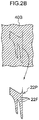
- the parts 22P, 24P and 26P are cut out as illustrated in Fig. 2A to 2C , with the orientation directions of the fibers 22F, 24F and 26F relative to the respective shapes matching up to orientation directions of the fibers 22F, 24F and 26F in the fabricated first structural portion 20 in a vehicle side view, as shown in Fig. 1 .
- the three parts 22P, 24P and 26P are arranged to form an assemblage 20P that forms an original shape of the first structural portion 20 (see Fig. 1 ).
- plural parts 30P are cut out from a prepreg sheet fabricated of fiber-reinforced resin, in which 12K twill fibers and a thermosetting resin are combined.
- the parts 30P are for forming the second structural portion 30 (see Fig. 1 ).
- the parts 30P are cut out as shown in Fig. 3A and Fig. 3B , with the orientation direction of the fibers 30F relative to the shape of the parts 30P, shown in Fig. 3B , matching up to the orientation direction of the fibers 30F in the fabricated second structural portion 30 in a vehicle side view, as shown in Fig. 1 .
- the assemblage 20P forming the original shape of the first structural portion 20 is placed on a platen 42 (or a mold), and the plural parts 30P for forming the second structural portion 30 (see Fig. 1 ) are placed on the assemblage 20P from above so as to be laminated.
- the assemblage 20P and parts 30P are depicted as being spaced apart by an appropriate spacing and the adjacent parts 30P are depicted as being spaced apart from one another by an appropriate spacing.
- the parts 30P are laminated in an appropriate number corresponding to the length direction of the spoiler 10.
- the section of the assemblage 20P shown in Fig. 3A corresponds to the section along line 3A-3A in Fig. 3B .
- the number of layers of the parts when the resin structure is being fabricated will vary with the size of the resin structure that is to be fabricated.
- the orientation direction of the fibers 22F in the first pattern portion 22 differs from the orientation directions of the fibers 24F and 26F in the second pattern portions 24 and 26, and these fibers 22F, 24F and 26F structure portions of the pattern.
- the portion of the fibers 30F that are contained in the region 32 of the second structural portion 30 that is superposed with the first structural portion 20 are configured so as to be visible through the resin of the first structural portion 20. Therefore, a sense of depth is provided to the pattern seen at the side at which the characteristic design surface 10S is disposed, and a pattern with a greater feeling of substance may be presented.
- the fibers 22F, 24F, 26F and 30F contained in the resin may be utilized to provide a sense of depth to a pattern seen at the side at which the characteristic design surface 10S is disposed.
- the first pattern portion 22 formed in the mark shape may seem to be floating and appear attractive. Thus, product appeal of the spoiler 10 is improved.
- a side face of the spoiler 10 of this exemplary embodiment no protrusions and indentations are formed as in, for example, a comparative structure in which a separate mark region is subsequently applied using metal plating, resin or the like.
- the side face of the spoiler 10 is flat, which is advantageous in regard to aerodynamic performance compared to the comparative structure.
- the fibers 22F, 24F and 26F are contained in the first structural portion 20 structuring the characteristic design surface 10S, which is advantageous from the aspect of rigidity compared to, for example, a structure in which the separate mark region of the comparative structure does not contain fibers.
- the fibers 30F contained in the second structural portion 30 are configured to have a greater fiber width than the fibers 22F, 24F and 26F contained in the first structural portion 20. Therefore, stiffness of the spoiler 10 may be raised further by the fibers 30F contained in the second structural portion 30 while a finely detailed pattern is presented by the fibers 22F, 24F and 26F contained in the first structural portion 20.
- Fig. 4 shows a side face of a spoiler 50 that serves as a resin structure according to the variant example.
- a characteristic design surface 50S that differs in design from the surroundings thereof is provided at a side face of the spoiler 50, in a central region (a predetermined region) of the side face.
- the variant example differs from the above exemplary embodiment in that a second pattern portion 54 is provided in place of the second pattern portion 24 according to the exemplary embodiment (illustrated in Fig. 1 ).
- An orientation direction of fibers 54F contained in the second pattern portion 54 according to the variant example is a little different from the orientation direction of the fibers 24F contained in the second pattern portion 24 according to the above exemplary embodiment shown in Fig. 1 .
- the second pattern portion 54 shown in Fig. 4 and the second pattern portion 24 according to the exemplary embodiment ( Fig. 1 ) have similar structures in other respects.
- a first structural portion 52 provided with the first pattern portion 22 and with the second pattern portions 26 and 54 has a similar structure to the first structural portion 20 according to the exemplary embodiment ( Fig. 1 ) except in the respects mentioned above.
- Fig. 4 in order to prevent difficulty in viewing of the drawing, similarly to Fig. 1 , the state of a portion of the fibers 30F being visible through the resin of the first structural portion 52 is not depicted in the drawing.
- the orientation direction of the fibers 22F of the first pattern portion 22 and the orientation direction of the fibers 54F of the second pattern portion 54 are configured to be directions that are orthogonal to one another. Therefore, in this variant example, further sense of depth is provided to the pattern seen at the side at which the characteristic design surface 50S is disposed, and the left side of the first pattern portion 22 in the drawing seems to be floating further (in other words, the pattern appears three-dimensional).
- carbon fibers are employed as reinforcing fibers contained in the resins.
- various publicly known fibers may be employed instead of carbon fibers such as, for example, resin fibers such as aramid fibers, cellulose fibers, nylon fibers, vinylon fibers, polyester fibers, polyolefin fibers, rayon fibers and the like, and glass fibers, metal fibers and so forth.
- the resins forming the spoilers 10 and 50 are thermosetting resins.
- a resin forming the resin structure may be a thermoplastic resin.
- the resin structure is the spoiler 10 or 50.
- the disclosure is not limited thereto and the resin structure may be employed at an alternative member such as, for example, a vehicle roof panel, hood panel, fender panel, door panel, side outer panel or the like.
- 3K twill fibers are employed as the fibers 22F, 24F, 26F and 54F contained in the first structural portions 20 and 52.
- fibers contained in the first structural portion are not limited to these fibers.
- the fibers 30F contained in the second structural portion 30 are configured to have greater fiber widths than the fibers 22F, 24F, 26F and 54F contained in the first structural portions 20 and 52.
- this structure is more preferable, a structure may be employed in which the fibers contained in the second structural portion are configured to have smaller fiber widths than the fibers contained in the first structural portion.
- plural numbers of the second pattern portions 24, 26 and 54 are provided.
- the disclosure is not limited thereto and a single second pattern portion may be provided rather than plural second pattern portions.
- the parts 30P shown in Fig. 3A are laminated in an appropriate number to fabricate the spoiler 10 shown in Fig. 1 .
- the disclosure is not limited thereto.
- a mode may be employed such that one layer each of an assemblage of sheet-shaped parts for forming the first structural portion and a sheet-shaped part for forming the second structural portion are laminated to fabricate a sheet-shaped resin structure, and this sheet-shaped resin structure is adhered to another component of a vehicle or the like.
Landscapes
- Engineering & Computer Science (AREA)
- Chemical & Material Sciences (AREA)
- Mechanical Engineering (AREA)
- Textile Engineering (AREA)
- Composite Materials (AREA)
- Combustion & Propulsion (AREA)
- Transportation (AREA)
- Laminated Bodies (AREA)
- Reinforced Plastic Materials (AREA)
Abstract
Description
- The present disclosure relates to a resin structure.
- Technologies are known that relate to resin structures containing fibers (see Japanese Patent Application Laid-Open (
JP-A) Nos. 2014-69390 H5-38798 JP-A No. 2014-69390 - However, in this technology, no consideration is given to utilizing the fibers in the laminated sheet to provide a sense of depth to the pattern as seen at a side at which a design surface is provided. There is scope for improvement in this regard.
- In consideration of the circumstances described above, the present disclosure provides a resin structure that may utilize fibers contained in a resin to provide a sense of depth to a pattern seen at a side at which a design surface is disposed.
- An aspect of the present disclosure is a resin structure that includes: a first structural portion that includes a characteristic design surface and structures an end portion at a side of the resin structure at which the characteristic design surface is disposed, the characteristic design surface being provided in a predetermined region and differing in design from surroundings thereof; and a second structural portion that is provided integrally with the first structural portion and includes a region disposed at the opposite side of the first structural portion from the side thereof at which the characteristic design surface is disposed, wherein the first structural portion includes: a first pattern portion that structures a first pattern at a center side of the characteristic design surface and that is formed from a resin containing fibers that structure a portion of the first pattern as seen from a side facing the characteristic design surface and are oriented in a first direction; and a second pattern portion that structures a second pattern at an outer periphery side of the characteristic design surface and that is disposed at the outer periphery side of the first pattern portion, the second pattern portion being formed from a resin containing fibers that structure a portion of the second pattern as seen from the side facing the characteristic design surface and are oriented in a second direction different from the first direction, and the second structural portion is formed from a resin containing fibers with a different fiber width from the fibers contained in the first structural portion, a portion of the fibers contained in a region of the second structural portion that is superposed with the first structural portion being configured so as to be visible through the resin of the first structural portion.
- The meaning of the term "fiber width" as used herein includes a maximum distance across a cross section orthogonal to a length direction of the fibers.
- According to the structure described above, in the first structural portion that includes the characteristic design surface and structures the end portion at the side at which the characteristic design surface is disposed, the orientation direction of the fibers in the first pattern portion differs from the orientation direction of the fibers in the second pattern portion, and these fibers structure portions of the pattern. The fibers contained in the second structural portion, which includes the region disposed at the opposite side of the first structural portion from the side at which the characteristic design surface is disposed, differ in fiber width from the fibers contained in the first structural portion. The portion of the fibers contained in the region of the second structural portion that is superposed with the first structural portion are configured so as to be visible through the resin of the first structural portion. As a result, a sense of depth is provided to the pattern seen at the side at which the characteristic design surface is disposed.
- In the above aspect, the fibers contained in the second structural portion may have a greater fiber width than the fibers contained in the first structural portion.
- According to the structure described above, stiffness of the resin structure may be raised by the fibers contained in the second structural portion, while a finely detailed pattern is presented by the fibers contained in the first structural portion.
- In the aspect, as seen from the side facing the characteristic design surface, the orientation direction of the fibers of the first pattern portion and the orientation direction of the fibers of the second pattern portion may be configured to be directions orthogonal to one another.
- According to the structure described above, because the orientation directions of the fibers of the first pattern portion and the second pattern portion are orthogonal to one another as seen from the side facing the characteristic design surface, further sense of depth is provided to the pattern seen at the side at which the characteristic design surface is disposed.
- As described above, according to the resin structure of the present disclosure, the fibers contained in the resin may be utilized to provide a sense of depth to the pattern seen at the side at which the characteristic design surface side is disposed.
- An exemplary embodiment of the present disclosure will be described in detail based on the following figures, wherein:
-
Fig. 1 is a perspective view showing a portion of a spoiler that serves as a resin structure according to an exemplary embodiment. -
Fig. 2A is a plan view for describing earlier steps when fabricating the spoiler ofFig. 1 , showing cutting of a part for a second pattern portion from a sheet. -
Fig. 2B is a plan view for describing the earlier steps when fabricating the spoiler ofFig. 1 , showing cutting of a part for a first pattern portion (a mark region) from a sheet. -
Fig. 2C is a plan view for describing the earlier steps when fabricating the spoiler ofFig. 1 , showing cutting of another part for the second pattern portion from a sheet. -
Fig. 2D is a plan view for describing the earlier steps when fabricating the spoiler ofFig. 1 , showing how the cut-out parts are arranged. -
Fig. 3A is a diagram for describing later steps when fabricating the spoiler ofFig. 1 , which is a vertical sectional diagram of an assemblage forming an original shape of a first structural portion, corresponding to a section alongline 3A-3A ofFig. 3B . -
Fig. 3B is a diagram for describing the later steps when fabricating the spoiler ofFig. 1 , which is a plan view showing the assemblage forming the original shape of the first structural portion and a part for forming a second structural portion. -
Fig. 4 is a side diagram showing a side view of a spoiler that serves as a resin structure according to a variant example. - A resin structure according to an exemplary embodiment is described using
Fig. 1 to Fig. 3B .Fig. 1 shows a perspective view of a portion of aspoiler 10 that serves as the resin structure according to the exemplary embodiment. An arrow FR inFig. 1 indicates a vehicle front side, an arrow UP indicates a vehicle upper side, and an arrow IN indicates a vehicle width direction inner side. - The
spoiler 10 shown inFig. 1 is also referred to as a rear wing spoiler, is provided at a vehiclerear portion 12 for airflow rectification, and is arranged along the vehicle width direction at an upper end portion of a back door panel 14. When seen from the vehicle upper side, a front end portion of thespoiler 10 extends in the vehicle width direction so as to run along a rear end portion of aroof panel 16, and a rear end portion of thespoiler 10 is formed so as to protrude toward the vehicle rear side. In a side face of thespoiler 10, acharacteristic design surface 10S that differs in design from the surroundings thereof is provided in a central region (a predetermined region) of thespoiler 10. - The
spoiler 10 includes a firststructural portion 20 and a secondstructural portion 30 that is provided integrally with the firststructural portion 20. The firststructural portion 20 includes thecharacteristic design surface 10S and structures an end portion at a side of thespoiler 10 at which thecharacteristic design surface 10S is provided. The secondstructural portion 30 includes a region that is disposed at the opposite side of the firststructural portion 20 from the side at which thecharacteristic design surface 10S is disposed. - The first
structural portion 20 is provided with afirst pattern portion 22 that structures a pattern of a mark region (a first pattern) at a central portion side of thecharacteristic design surface 10S. Thefirst pattern portion 22 is formed in the shape of a predetermined mark (in this exemplary embodiment, a designed shape based on the letter "F"). Thefirst pattern portion 22 is formed from aresin containing fibers 22F. Thefibers 22F structure a portion of the pattern of the mark region (the first pattern) as seen from a side facing thecharacteristic design surface 10S, and are oriented in one direction (in this exemplary embodiment, a direction that is angled to the vehicle lower side toward the vehicle rear side). - The first
structural portion 20 is further provided withsecond pattern portions characteristic design surface 10S and are disposed at the outer periphery side of thefirst pattern portion 22. Thesecond pattern portion 24 is disposed at the vehicle front side of the first pattern portion 22 (the left side of the mark), and thesecond pattern portion 26 is arranged so as to encircle thefirst pattern portion 22 and thesecond pattern portion 24. Thesecond pattern portions resins containing fibers fibers characteristic design surface 10S. Thefibers fibers 22F of the first pattern portion 22 (the one direction). Specifically, thefibers 24F are oriented in a direction that is angled to the vehicle upper side toward the vehicle rear side, and thefibers 26F are oriented along the vehicle front-and-rear direction. - In this exemplary embodiment, fibers that are employed as the
fibers structural portion 20 are, for example, 3K twill fibers (that is, fibers formed by twisting 3,000 carbon fiber filaments). - The second
structural portion 30 structures most of thespoiler 10. The secondstructural portion 30 is provided with aregion 32 that is superposed with the first structural portion 20 (see the region enclosed by two-dot chain lines in the drawings) and aregion 34 that is not superposed with the firststructural portion 20. Theregion 34 of the secondstructural portion 30 that is not superposed with the firststructural portion 20 includes aregion 34X that is disposed at the outer periphery side of the firststructural portion 20, and aregion 34Y that is superposed with theregion 34X disposed at the outer periphery side of the firststructural portion 20. The surface of theregion 34X of the secondstructural portion 30 that is disposed at the outer periphery side of the firststructural portion 20 is aligned with the surface of the firststructural portion 20. - The second
structural portion 30 is formed form aresin containing fibers 30F with a different fiber width from thefibers structural portion 20. As an example, thefibers 30F are oriented in a direction that is angled to the vehicle lower side toward the vehicle rear side. InFig. 1 , in order to aid viewing of the drawing, those of thefibers 30F that can be seen from the side of thespoiler 10 at which anupper face 30U is provided are not shown in the drawing. In this exemplary embodiment, thefibers 30F contained in the secondstructural portion 30 are configured to have greater fiber widths than thefibers structural portion 20. The fibers that are employed as thefibers 30F contained in the secondstructural portion 30 are, for example, 12K twill fibers (that is, fibers formed by twisting 12,000 carbon fiber filaments). - Resins that are employed as the resin forming the first
structural portion 20 and the resin forming the secondstructural portion 30 are materials featuring transparency to light. The portion of thefibers 30F that are contained in theregion 32 superposed with the firststructural portion 20 are configured so as to be visible through the resin of the firststructural portion 20. InFig. 1 , in order to prevent difficulty in viewing of the drawing, the state of this portion of thefibers 30F being visible is not depicted in the drawing. Accordingly, to add to this description, thefibers 30F in linear shapes that can be seen adjacent to the outer periphery side of the firststructural portion 20 extend in linear shapes at a back side (the vehicle width direction inner side) of the firststructural portion 20, and are configured such that thesefibers 30F at the back side of the resin of the firststructural portion 20 can be seen. - Now, a fabrication method of the
spoiler 10 shown inFig. 1 is described with reference tofig 2A to Fig. 2D andFig. 3A to Fig. 3B . - First,
parts prepreg sheets parts first pattern portion 22 and thesecond pattern portions 24 and 26 (all shown inFig. 1 ). Theparts Fig. 2A to 2C , with the orientation directions of thefibers fibers structural portion 20 in a vehicle side view, as shown inFig. 1 . As shown inFig. 2D , the threeparts assemblage 20P that forms an original shape of the first structural portion 20 (seeFig. 1 ). - Further, although not shown in the drawings,
plural parts 30P (seeFig. 3A and Fig. 3B ) are cut out from a prepreg sheet fabricated of fiber-reinforced resin, in which 12K twill fibers and a thermosetting resin are combined. Theparts 30P are for forming the second structural portion 30 (seeFig. 1 ). Similarly, theparts 30P are cut out as shown inFig. 3A and Fig. 3B , with the orientation direction of thefibers 30F relative to the shape of theparts 30P, shown inFig. 3B , matching up to the orientation direction of thefibers 30F in the fabricated secondstructural portion 30 in a vehicle side view, as shown inFig. 1 . - Then, as shown in
Fig. 3A , theassemblage 20P forming the original shape of the first structural portion 20 (seeFig. 1 ) is placed on a platen 42 (or a mold), and theplural parts 30P for forming the second structural portion 30 (seeFig. 1 ) are placed on theassemblage 20P from above so as to be laminated. InFig. 3A , in order to aid viewing of the drawing, theassemblage 20P andparts 30P are depicted as being spaced apart by an appropriate spacing and theadjacent parts 30P are depicted as being spaced apart from one another by an appropriate spacing. Theparts 30P are laminated in an appropriate number corresponding to the length direction of thespoiler 10. The section of theassemblage 20P shown inFig. 3A corresponds to the section alongline 3A-3A inFig. 3B . - After the
assemblage 20P and theplural parts 30P shown inFig. 3A have been laminated, vacuum heat pressing is performed and the same are cured. Thus, bonding and setting of theparts spoiler 10 illustrated inFig. 1 is provided by the above steps. - Obviously, the number of layers of the parts when the resin structure is being fabricated will vary with the size of the resin structure that is to be fabricated.
- Now, operation and effects of the above exemplary embodiment are described.
- As shown in
Fig. 1 , in the firststructural portion 20 that includes thecharacteristic design surface 10S and structures the end portion at the side of thespoiler 10 at which thecharacteristic design surface 10S is provided, the orientation direction of thefibers 22F in thefirst pattern portion 22 differs from the orientation directions of thefibers second pattern portions fibers fibers 30F contained in the secondstructural portion 30, which includes the region that is disposed at the opposite side of the firststructural portion 20 from the side at which thecharacteristic design surface 10S is provided, have a different fiber width from thefibers structural portion 20. The portion of thefibers 30F that are contained in theregion 32 of the secondstructural portion 30 that is superposed with the firststructural portion 20 are configured so as to be visible through the resin of the firststructural portion 20. Therefore, a sense of depth is provided to the pattern seen at the side at which thecharacteristic design surface 10S is disposed, and a pattern with a greater feeling of substance may be presented. - As described above, according to the
spoiler 10 that serves as the resin structure of this exemplary embodiment, thefibers characteristic design surface 10S is disposed. In this exemplary embodiment, thefirst pattern portion 22 formed in the mark shape may seem to be floating and appear attractive. Thus, product appeal of thespoiler 10 is improved. - In a side face of the
spoiler 10 of this exemplary embodiment, no protrusions and indentations are formed as in, for example, a comparative structure in which a separate mark region is subsequently applied using metal plating, resin or the like. Thus, the side face of thespoiler 10 is flat, which is advantageous in regard to aerodynamic performance compared to the comparative structure. In this exemplary embodiment, thefibers structural portion 20 structuring thecharacteristic design surface 10S, which is advantageous from the aspect of rigidity compared to, for example, a structure in which the separate mark region of the comparative structure does not contain fibers. - In this exemplary embodiment, subsequent application as in the comparative structure is not necessary, and the mark region may be included and integrally formed in the
spoiler 10. Therefore, costs may be reduced. - In this exemplary embodiment, the
fibers 30F contained in the secondstructural portion 30 are configured to have a greater fiber width than thefibers structural portion 20. Therefore, stiffness of thespoiler 10 may be raised further by thefibers 30F contained in the secondstructural portion 30 while a finely detailed pattern is presented by thefibers structural portion 20. - Now, a variant example of the above exemplary embodiment is described with reference to
Fig. 4. Fig. 4 shows a side face of aspoiler 50 that serves as a resin structure according to the variant example. Acharacteristic design surface 50S that differs in design from the surroundings thereof is provided at a side face of thespoiler 50, in a central region (a predetermined region) of the side face. The variant example differs from the above exemplary embodiment in that asecond pattern portion 54 is provided in place of thesecond pattern portion 24 according to the exemplary embodiment (illustrated inFig. 1 ). An orientation direction offibers 54F contained in thesecond pattern portion 54 according to the variant example is a little different from the orientation direction of thefibers 24F contained in thesecond pattern portion 24 according to the above exemplary embodiment shown inFig. 1 . Thesecond pattern portion 54 shown inFig. 4 and thesecond pattern portion 24 according to the exemplary embodiment (Fig. 1 ) have similar structures in other respects. In the variant example, a firststructural portion 52 provided with thefirst pattern portion 22 and with thesecond pattern portions structural portion 20 according to the exemplary embodiment (Fig. 1 ) except in the respects mentioned above. - Below, structural portions that are substantially the same as in the above exemplary embodiment shown in
Fig. 1 are assigned the same reference numerals and are not described. - In
Fig. 4 , in order to prevent difficulty in viewing of the drawing, similarly toFig. 1 , the state of a portion of thefibers 30F being visible through the resin of the firststructural portion 52 is not depicted in the drawing. - As shown in
Fig. 4 , as seen from the side facing thecharacteristic design surface 50S, the orientation direction of thefibers 22F of thefirst pattern portion 22 and the orientation direction of thefibers 54F of thesecond pattern portion 54 are configured to be directions that are orthogonal to one another. Therefore, in this variant example, further sense of depth is provided to the pattern seen at the side at which thecharacteristic design surface 50S is disposed, and the left side of thefirst pattern portion 22 in the drawing seems to be floating further (in other words, the pattern appears three-dimensional). - In the exemplary embodiment and variant example shown in
Fig. 1 andFig. 4 , carbon fibers are employed as reinforcing fibers contained in the resins. However, various publicly known fibers may be employed instead of carbon fibers such as, for example, resin fibers such as aramid fibers, cellulose fibers, nylon fibers, vinylon fibers, polyester fibers, polyolefin fibers, rayon fibers and the like, and glass fibers, metal fibers and so forth. - In the exemplary embodiment and variant example shown in
Fig. 1 andFig. 4 , the resins forming thespoilers - In the exemplary embodiment and variant example shown in
Fig. 1 andFig. 4 , the resin structure is thespoiler - In the exemplary embodiment and variant example shown in
Fig. 1 andFig. 4 , 3K twill fibers are employed as thefibers structural portions - In the exemplary embodiment and variant example shown in
Fig. 1 andFig. 4 , thefibers 30F contained in the secondstructural portion 30 are configured to have greater fiber widths than thefibers structural portions - In the exemplary embodiment and variant example shown in
Fig. 1 andFig. 4 , plural numbers of thesecond pattern portions - In the above exemplary embodiment, the
parts 30P shown inFig. 3A are laminated in an appropriate number to fabricate thespoiler 10 shown inFig. 1 . However, the disclosure is not limited thereto. For example, a mode may be employed such that one layer each of an assemblage of sheet-shaped parts for forming the first structural portion and a sheet-shaped part for forming the second structural portion are laminated to fabricate a sheet-shaped resin structure, and this sheet-shaped resin structure is adhered to another component of a vehicle or the like. - The exemplary embodiment described above and variant examples mentioned above may be embodied in suitable combinations.
- Hereabove, examples of the present disclosure have been described. The present disclosure is not limited by these descriptions and it will be clear that numerous modifications beyond these descriptions may be embodied within a technical scope not departing from the gist of the disclosure.
Claims (3)
- A resin structure (10, 50) comprising:a first structural portion (20) that includes a characteristic design surface (10S, 50S) and structures an end portion at a side of the resin structure at which the characteristic design surface (10S, 50S) is disposed, the characteristic design surface (10S, 50S) being provided in a predetermined region and differing in design from surroundings thereof; anda second structural portion (30) that is provided integrally with the first structural portion (20) and includes a region disposed at the opposite side of the first structural portion (20) from the side thereof at which the characteristic design surface (10S, 50S) is disposed,and the second structural portion (30) is formed from a resin containing fibers (30F) with a different fiber width from the fibers (22F, 24F, 26F, 54F) contained in the first structural portion (20), a portion of the fibers (30F) contained in a region of the second structural portion that is superposed with the first structural portion (20) being configured so as to be visible through the resin of the first structural portion (20).
wherein the first structural portion (20) includes:a first pattern portion (22) that structures a first pattern at a center side of the characteristic design surface (10S, 50S) and that is formed from a resin containing fibers (22F) that structure a portion of the first pattern as seen from a side facing the characteristic design surface (10S, 50S) and are oriented in a first direction; anda second pattern portion (24, 26, 54) that structures a second pattern at an outer periphery side of the characteristic design surface (10S, 50S) and that is disposed at the outer periphery side of the first pattern portion (22), the second pattern portion (24, 26, 54) being formed from a resin containing fibers (24F, 26F, 54F) that structure a portion of the second pattern as seen from the side facing the characteristic design surface (10S, 50S) and are oriented in a second direction different from the first direction, - The resin structure (10, 50) according to claim 1, wherein the fibers (30F) contained in the second structural portion (30) have a greater fiber width than the fibers (22F, 24F, 26F, 54F) contained in the first structural portion (20).
- The resin structure (50) according to claim 1 or claim 2, wherein, as seen from the side facing the characteristic design surface (50S), the orientation direction of the fibers (22F) of the first pattern portion (22) and the orientation direction of the fibers (54F) of the second pattern portion (54) are configured to be directions orthogonal to one another.
Applications Claiming Priority (1)
| Application Number | Priority Date | Filing Date | Title |
|---|---|---|---|
| JP2017152638A JP6777044B2 (en) | 2017-08-07 | 2017-08-07 | Resin structure |
Publications (2)
| Publication Number | Publication Date |
|---|---|
| EP3441219A1 true EP3441219A1 (en) | 2019-02-13 |
| EP3441219B1 EP3441219B1 (en) | 2020-02-26 |
Family
ID=63449169
Family Applications (1)
| Application Number | Title | Priority Date | Filing Date |
|---|---|---|---|
| EP18187298.7A Active EP3441219B1 (en) | 2017-08-07 | 2018-08-03 | Resin structure |
Country Status (4)
| Country | Link |
|---|---|
| US (1) | US10518502B2 (en) |
| EP (1) | EP3441219B1 (en) |
| JP (1) | JP6777044B2 (en) |
| CN (1) | CN109383642B (en) |
Families Citing this family (2)
| Publication number | Priority date | Publication date | Assignee | Title |
|---|---|---|---|---|
| US11673618B2 (en) | 2021-03-31 | 2023-06-13 | Honda Motor Co., Ltd. | Flexible and storable active spoiler system |
| US11787485B2 (en) | 2021-03-31 | 2023-10-17 | Honda Motor Co., Ltd. | Flexible and storable active spoiler system |
Citations (5)
| Publication number | Priority date | Publication date | Assignee | Title |
|---|---|---|---|---|
| US3768760A (en) * | 1970-10-30 | 1973-10-30 | Hercules Inc | Graphite fiber composite covering employing multi-directional |
| JPH0538798A (en) | 1991-02-05 | 1993-02-19 | Sakai Composite Kk | Fiber-reinforced resin molding |
| EP1600288A1 (en) * | 2004-05-28 | 2005-11-30 | Panolam Industries International, Inc | Fiber-reinforced decorative laminate |
| JP2014069390A (en) | 2012-09-28 | 2014-04-21 | Dainippon Printing Co Ltd | Laminate sheet |
| EP3181325A1 (en) * | 2015-11-30 | 2017-06-21 | Toyota Jidosha Kabushiki Kaisha | Resin body and manufacturing method of resin body |
Family Cites Families (12)
| Publication number | Priority date | Publication date | Assignee | Title |
|---|---|---|---|---|
| GB2091649B (en) * | 1981-01-23 | 1985-05-22 | Alloy Transport Bodies Ltd | A combined sleeping compartment and wind deflector structure for a commercial vehicle cab top |
| JP3540499B2 (en) * | 1996-03-01 | 2004-07-07 | 昭和飛行機工業株式会社 | Wind deflectors for trucks, etc. |
| JP3429192B2 (en) * | 1998-04-30 | 2003-07-22 | カネボウ合繊株式会社 | Automotive headlining |
| DE10000006C2 (en) * | 2000-01-03 | 2003-09-18 | Herbert Michels | Entry panel for a truck cab |
| JP2002036408A (en) * | 2000-07-26 | 2002-02-05 | Matsushita Electric Works Ltd | Decorative board |
| DE10217111A1 (en) * | 2002-04-17 | 2003-11-06 | Roehm Gmbh | Solid with microstructured surface |
| WO2005095079A1 (en) * | 2004-03-30 | 2005-10-13 | Toray Industries, Inc. | Preform, frp, and processes for producing these |
| JP4414815B2 (en) * | 2004-05-31 | 2010-02-10 | グローブライド株式会社 | Tubular body |
| GB0416197D0 (en) * | 2004-07-20 | 2004-08-18 | B I Group Plc | Composite plastic and related manufacturing methods |
| JP2007001521A (en) * | 2005-06-27 | 2007-01-11 | Mazda Motor Corp | Car body rear structure |
| CN201208990Y (en) * | 2008-04-25 | 2009-03-18 | 中国第一汽车集团公司 | Dome mechanism for steering room roof cover |
| RU2519574C1 (en) * | 2010-04-08 | 2014-06-20 | Ниссан Мотор Ко., Лтд. | Front underfloor structure of vehicle |
-
2017
- 2017-08-07 JP JP2017152638A patent/JP6777044B2/en active Active
-
2018
- 2018-07-26 US US16/046,398 patent/US10518502B2/en active Active
- 2018-08-01 CN CN201810865343.2A patent/CN109383642B/en not_active Expired - Fee Related
- 2018-08-03 EP EP18187298.7A patent/EP3441219B1/en active Active
Patent Citations (5)
| Publication number | Priority date | Publication date | Assignee | Title |
|---|---|---|---|---|
| US3768760A (en) * | 1970-10-30 | 1973-10-30 | Hercules Inc | Graphite fiber composite covering employing multi-directional |
| JPH0538798A (en) | 1991-02-05 | 1993-02-19 | Sakai Composite Kk | Fiber-reinforced resin molding |
| EP1600288A1 (en) * | 2004-05-28 | 2005-11-30 | Panolam Industries International, Inc | Fiber-reinforced decorative laminate |
| JP2014069390A (en) | 2012-09-28 | 2014-04-21 | Dainippon Printing Co Ltd | Laminate sheet |
| EP3181325A1 (en) * | 2015-11-30 | 2017-06-21 | Toyota Jidosha Kabushiki Kaisha | Resin body and manufacturing method of resin body |
Also Published As
| Publication number | Publication date |
|---|---|
| JP6777044B2 (en) | 2020-10-28 |
| US10518502B2 (en) | 2019-12-31 |
| JP2019031007A (en) | 2019-02-28 |
| CN109383642A (en) | 2019-02-26 |
| CN109383642B (en) | 2021-02-05 |
| US20190039345A1 (en) | 2019-02-07 |
| EP3441219B1 (en) | 2020-02-26 |
Similar Documents
| Publication | Publication Date | Title |
|---|---|---|
| US6702911B2 (en) | Composite material-stiffened panel and manufacturing method thereof | |
| JP4425422B2 (en) | Method for producing composite material structure and composite material structure produced thereby | |
| US8636936B2 (en) | Method for fabricating a laminated fiber metal composite | |
| EP1712462B1 (en) | Crank for bicycle and method of producing the same | |
| EP3441219B1 (en) | Resin structure | |
| CN104648488B (en) | Housing components for vehicles | |
| JP7218596B2 (en) | Edge structure of fiber reinforced resin structure | |
| JP6272202B2 (en) | Bending part in composite panel | |
| WO2002055384A2 (en) | Composite structural panel with undulated body | |
| US10518489B2 (en) | Composite structures incorporating additive manufactured components | |
| JP6361024B2 (en) | Resin structure and electric vacuum cleaner using the same | |
| JP2015178241A (en) | Method of producing fiber-reinforced resin material | |
| JP7412458B2 (en) | Composite material structure manufacturing method, laminate manufacturing method, laminate and laminate type | |
| JP6859448B2 (en) | Manufacturing method of fiber reinforced resin member, fuel tank and fiber reinforced resin member | |
| JP7385480B2 (en) | Laminate and method for manufacturing the laminate | |
| US20180251205A1 (en) | Aircraft cabin panel and method of manufacturing the same | |
| CN110920094A (en) | Fiber-reinforced resin structure | |
| JP2016221885A (en) | Fiber-reinforced resin structure and manufacturing process thereof | |
| EP4119334B1 (en) | Composite material structure and manufacturing method of composite material structure | |
| US11993030B2 (en) | Composite material component shaping method and charge | |
| EP4673326A1 (en) | Underbody protection means for motor vehicles, battery housing for a traction battery, traction battery for motor vehicles, and motor vehicle with an underbody protection means | |
| US20230302767A1 (en) | Layered body structure and method for manufacturing layered body structure | |
| JP6484378B1 (en) | Resin molded product and method for producing resin molded product | |
| KR102937679B1 (en) | Lower Housing Of Battery Pack For Electric Vehicle | |
| KR20040024334A (en) | Fiber reinforced composite sabots and thereof reinforcement manufacturing method |
Legal Events
| Date | Code | Title | Description |
|---|---|---|---|
| PUAI | Public reference made under article 153(3) epc to a published international application that has entered the european phase |
Free format text: ORIGINAL CODE: 0009012 |
|
| STAA | Information on the status of an ep patent application or granted ep patent |
Free format text: STATUS: REQUEST FOR EXAMINATION WAS MADE |
|
| 17P | Request for examination filed |
Effective date: 20180803 |
|
| AK | Designated contracting states |
Kind code of ref document: A1 Designated state(s): AL AT BE BG CH CY CZ DE DK EE ES FI FR GB GR HR HU IE IS IT LI LT LU LV MC MK MT NL NO PL PT RO RS SE SI SK SM TR |
|
| AX | Request for extension of the european patent |
Extension state: BA ME |
|
| GRAP | Despatch of communication of intention to grant a patent |
Free format text: ORIGINAL CODE: EPIDOSNIGR1 |
|
| STAA | Information on the status of an ep patent application or granted ep patent |
Free format text: STATUS: GRANT OF PATENT IS INTENDED |
|
| INTG | Intention to grant announced |
Effective date: 20190926 |
|
| GRAS | Grant fee paid |
Free format text: ORIGINAL CODE: EPIDOSNIGR3 |
|
| GRAA | (expected) grant |
Free format text: ORIGINAL CODE: 0009210 |
|
| STAA | Information on the status of an ep patent application or granted ep patent |
Free format text: STATUS: THE PATENT HAS BEEN GRANTED |
|
| AK | Designated contracting states |
Kind code of ref document: B1 Designated state(s): AL AT BE BG CH CY CZ DE DK EE ES FI FR GB GR HR HU IE IS IT LI LT LU LV MC MK MT NL NO PL PT RO RS SE SI SK SM TR |
|
| REG | Reference to a national code |
Ref country code: GB Ref legal event code: FG4D |
|
| REG | Reference to a national code |
Ref country code: CH Ref legal event code: EP |
|
| REG | Reference to a national code |
Ref country code: DE Ref legal event code: R096 Ref document number: 602018002684 Country of ref document: DE |
|
| REG | Reference to a national code |
Ref country code: AT Ref legal event code: REF Ref document number: 1237119 Country of ref document: AT Kind code of ref document: T Effective date: 20200315 |
|
| REG | Reference to a national code |
Ref country code: IE Ref legal event code: FG4D |
|
| PG25 | Lapsed in a contracting state [announced via postgrant information from national office to epo] |
Ref country code: NO Free format text: LAPSE BECAUSE OF FAILURE TO SUBMIT A TRANSLATION OF THE DESCRIPTION OR TO PAY THE FEE WITHIN THE PRESCRIBED TIME-LIMIT Effective date: 20200526 Ref country code: RS Free format text: LAPSE BECAUSE OF FAILURE TO SUBMIT A TRANSLATION OF THE DESCRIPTION OR TO PAY THE FEE WITHIN THE PRESCRIBED TIME-LIMIT Effective date: 20200226 Ref country code: FI Free format text: LAPSE BECAUSE OF FAILURE TO SUBMIT A TRANSLATION OF THE DESCRIPTION OR TO PAY THE FEE WITHIN THE PRESCRIBED TIME-LIMIT Effective date: 20200226 |
|
| REG | Reference to a national code |
Ref country code: NL Ref legal event code: MP Effective date: 20200226 |
|
| REG | Reference to a national code |
Ref country code: LT Ref legal event code: MG4D |
|
| PG25 | Lapsed in a contracting state [announced via postgrant information from national office to epo] |
Ref country code: BG Free format text: LAPSE BECAUSE OF FAILURE TO SUBMIT A TRANSLATION OF THE DESCRIPTION OR TO PAY THE FEE WITHIN THE PRESCRIBED TIME-LIMIT Effective date: 20200526 Ref country code: IS Free format text: LAPSE BECAUSE OF FAILURE TO SUBMIT A TRANSLATION OF THE DESCRIPTION OR TO PAY THE FEE WITHIN THE PRESCRIBED TIME-LIMIT Effective date: 20200626 Ref country code: GR Free format text: LAPSE BECAUSE OF FAILURE TO SUBMIT A TRANSLATION OF THE DESCRIPTION OR TO PAY THE FEE WITHIN THE PRESCRIBED TIME-LIMIT Effective date: 20200527 Ref country code: HR Free format text: LAPSE BECAUSE OF FAILURE TO SUBMIT A TRANSLATION OF THE DESCRIPTION OR TO PAY THE FEE WITHIN THE PRESCRIBED TIME-LIMIT Effective date: 20200226 Ref country code: LV Free format text: LAPSE BECAUSE OF FAILURE TO SUBMIT A TRANSLATION OF THE DESCRIPTION OR TO PAY THE FEE WITHIN THE PRESCRIBED TIME-LIMIT Effective date: 20200226 Ref country code: SE Free format text: LAPSE BECAUSE OF FAILURE TO SUBMIT A TRANSLATION OF THE DESCRIPTION OR TO PAY THE FEE WITHIN THE PRESCRIBED TIME-LIMIT Effective date: 20200226 |
|
| PG25 | Lapsed in a contracting state [announced via postgrant information from national office to epo] |
Ref country code: NL Free format text: LAPSE BECAUSE OF FAILURE TO SUBMIT A TRANSLATION OF THE DESCRIPTION OR TO PAY THE FEE WITHIN THE PRESCRIBED TIME-LIMIT Effective date: 20200226 |
|
| PG25 | Lapsed in a contracting state [announced via postgrant information from national office to epo] |
Ref country code: ES Free format text: LAPSE BECAUSE OF FAILURE TO SUBMIT A TRANSLATION OF THE DESCRIPTION OR TO PAY THE FEE WITHIN THE PRESCRIBED TIME-LIMIT Effective date: 20200226 Ref country code: PT Free format text: LAPSE BECAUSE OF FAILURE TO SUBMIT A TRANSLATION OF THE DESCRIPTION OR TO PAY THE FEE WITHIN THE PRESCRIBED TIME-LIMIT Effective date: 20200719 Ref country code: LT Free format text: LAPSE BECAUSE OF FAILURE TO SUBMIT A TRANSLATION OF THE DESCRIPTION OR TO PAY THE FEE WITHIN THE PRESCRIBED TIME-LIMIT Effective date: 20200226 Ref country code: RO Free format text: LAPSE BECAUSE OF FAILURE TO SUBMIT A TRANSLATION OF THE DESCRIPTION OR TO PAY THE FEE WITHIN THE PRESCRIBED TIME-LIMIT Effective date: 20200226 Ref country code: CZ Free format text: LAPSE BECAUSE OF FAILURE TO SUBMIT A TRANSLATION OF THE DESCRIPTION OR TO PAY THE FEE WITHIN THE PRESCRIBED TIME-LIMIT Effective date: 20200226 Ref country code: SK Free format text: LAPSE BECAUSE OF FAILURE TO SUBMIT A TRANSLATION OF THE DESCRIPTION OR TO PAY THE FEE WITHIN THE PRESCRIBED TIME-LIMIT Effective date: 20200226 Ref country code: SM Free format text: LAPSE BECAUSE OF FAILURE TO SUBMIT A TRANSLATION OF THE DESCRIPTION OR TO PAY THE FEE WITHIN THE PRESCRIBED TIME-LIMIT Effective date: 20200226 Ref country code: EE Free format text: LAPSE BECAUSE OF FAILURE TO SUBMIT A TRANSLATION OF THE DESCRIPTION OR TO PAY THE FEE WITHIN THE PRESCRIBED TIME-LIMIT Effective date: 20200226 Ref country code: DK Free format text: LAPSE BECAUSE OF FAILURE TO SUBMIT A TRANSLATION OF THE DESCRIPTION OR TO PAY THE FEE WITHIN THE PRESCRIBED TIME-LIMIT Effective date: 20200226 |
|
| REG | Reference to a national code |
Ref country code: AT Ref legal event code: MK05 Ref document number: 1237119 Country of ref document: AT Kind code of ref document: T Effective date: 20200226 |
|
| REG | Reference to a national code |
Ref country code: DE Ref legal event code: R097 Ref document number: 602018002684 Country of ref document: DE |
|
| PLBE | No opposition filed within time limit |
Free format text: ORIGINAL CODE: 0009261 |
|
| STAA | Information on the status of an ep patent application or granted ep patent |
Free format text: STATUS: NO OPPOSITION FILED WITHIN TIME LIMIT |
|
| PG25 | Lapsed in a contracting state [announced via postgrant information from national office to epo] |
Ref country code: IT Free format text: LAPSE BECAUSE OF FAILURE TO SUBMIT A TRANSLATION OF THE DESCRIPTION OR TO PAY THE FEE WITHIN THE PRESCRIBED TIME-LIMIT Effective date: 20200226 Ref country code: AT Free format text: LAPSE BECAUSE OF FAILURE TO SUBMIT A TRANSLATION OF THE DESCRIPTION OR TO PAY THE FEE WITHIN THE PRESCRIBED TIME-LIMIT Effective date: 20200226 |
|
| 26N | No opposition filed |
Effective date: 20201127 |
|
| PG25 | Lapsed in a contracting state [announced via postgrant information from national office to epo] |
Ref country code: SI Free format text: LAPSE BECAUSE OF FAILURE TO SUBMIT A TRANSLATION OF THE DESCRIPTION OR TO PAY THE FEE WITHIN THE PRESCRIBED TIME-LIMIT Effective date: 20200226 Ref country code: PL Free format text: LAPSE BECAUSE OF FAILURE TO SUBMIT A TRANSLATION OF THE DESCRIPTION OR TO PAY THE FEE WITHIN THE PRESCRIBED TIME-LIMIT Effective date: 20200226 |
|
| PG25 | Lapsed in a contracting state [announced via postgrant information from national office to epo] |
Ref country code: MC Free format text: LAPSE BECAUSE OF FAILURE TO SUBMIT A TRANSLATION OF THE DESCRIPTION OR TO PAY THE FEE WITHIN THE PRESCRIBED TIME-LIMIT Effective date: 20200226 |
|
| PG25 | Lapsed in a contracting state [announced via postgrant information from national office to epo] |
Ref country code: LU Free format text: LAPSE BECAUSE OF NON-PAYMENT OF DUE FEES Effective date: 20200803 |
|
| REG | Reference to a national code |
Ref country code: BE Ref legal event code: MM Effective date: 20200831 |
|
| PGFP | Annual fee paid to national office [announced via postgrant information from national office to epo] |
Ref country code: FR Payment date: 20210611 Year of fee payment: 4 |
|
| PG25 | Lapsed in a contracting state [announced via postgrant information from national office to epo] |
Ref country code: IE Free format text: LAPSE BECAUSE OF NON-PAYMENT OF DUE FEES Effective date: 20200803 Ref country code: BE Free format text: LAPSE BECAUSE OF NON-PAYMENT OF DUE FEES Effective date: 20200831 |
|
| PGFP | Annual fee paid to national office [announced via postgrant information from national office to epo] |
Ref country code: DE Payment date: 20210630 Year of fee payment: 4 |
|
| REG | Reference to a national code |
Ref country code: DE Ref legal event code: R084 Ref document number: 602018002684 Country of ref document: DE |
|
| REG | Reference to a national code |
Ref country code: CH Ref legal event code: PL |
|
| PG25 | Lapsed in a contracting state [announced via postgrant information from national office to epo] |
Ref country code: LI Free format text: LAPSE BECAUSE OF NON-PAYMENT OF DUE FEES Effective date: 20210831 Ref country code: CH Free format text: LAPSE BECAUSE OF NON-PAYMENT OF DUE FEES Effective date: 20210831 |
|
| PG25 | Lapsed in a contracting state [announced via postgrant information from national office to epo] |
Ref country code: TR Free format text: LAPSE BECAUSE OF FAILURE TO SUBMIT A TRANSLATION OF THE DESCRIPTION OR TO PAY THE FEE WITHIN THE PRESCRIBED TIME-LIMIT Effective date: 20200226 Ref country code: MT Free format text: LAPSE BECAUSE OF FAILURE TO SUBMIT A TRANSLATION OF THE DESCRIPTION OR TO PAY THE FEE WITHIN THE PRESCRIBED TIME-LIMIT Effective date: 20200226 Ref country code: CY Free format text: LAPSE BECAUSE OF FAILURE TO SUBMIT A TRANSLATION OF THE DESCRIPTION OR TO PAY THE FEE WITHIN THE PRESCRIBED TIME-LIMIT Effective date: 20200226 |
|
| REG | Reference to a national code |
Ref country code: GB Ref legal event code: 746 Effective date: 20220509 |
|
| PG25 | Lapsed in a contracting state [announced via postgrant information from national office to epo] |
Ref country code: MK Free format text: LAPSE BECAUSE OF FAILURE TO SUBMIT A TRANSLATION OF THE DESCRIPTION OR TO PAY THE FEE WITHIN THE PRESCRIBED TIME-LIMIT Effective date: 20200226 Ref country code: AL Free format text: LAPSE BECAUSE OF FAILURE TO SUBMIT A TRANSLATION OF THE DESCRIPTION OR TO PAY THE FEE WITHIN THE PRESCRIBED TIME-LIMIT Effective date: 20200226 |
|
| REG | Reference to a national code |
Ref country code: DE Ref legal event code: R119 Ref document number: 602018002684 Country of ref document: DE |
|
| GBPC | Gb: european patent ceased through non-payment of renewal fee |
Effective date: 20220803 |
|
| PG25 | Lapsed in a contracting state [announced via postgrant information from national office to epo] |
Ref country code: FR Free format text: LAPSE BECAUSE OF NON-PAYMENT OF DUE FEES Effective date: 20220831 Ref country code: DE Free format text: LAPSE BECAUSE OF NON-PAYMENT OF DUE FEES Effective date: 20230301 |
|
| PG25 | Lapsed in a contracting state [announced via postgrant information from national office to epo] |
Ref country code: GB Free format text: LAPSE BECAUSE OF NON-PAYMENT OF DUE FEES Effective date: 20220803 |