EP3440825B1 - Freisprechtelefonkonfiguration für konferenzen - Google Patents
Freisprechtelefonkonfiguration für konferenzen Download PDFInfo
- Publication number
- EP3440825B1 EP3440825B1 EP16823388.0A EP16823388A EP3440825B1 EP 3440825 B1 EP3440825 B1 EP 3440825B1 EP 16823388 A EP16823388 A EP 16823388A EP 3440825 B1 EP3440825 B1 EP 3440825B1
- Authority
- EP
- European Patent Office
- Prior art keywords
- speakerphone
- port
- wall
- cable
- speakerphones
- Prior art date
- Legal status (The legal status is an assumption and is not a legal conclusion. Google has not performed a legal analysis and makes no representation as to the accuracy of the status listed.)
- Active
Links
Images








Classifications
-
- H—ELECTRICITY
- H04—ELECTRIC COMMUNICATION TECHNIQUE
- H04M—TELEPHONIC COMMUNICATION
- H04M1/00—Substation equipment, e.g. for use by subscribers
- H04M1/60—Substation equipment, e.g. for use by subscribers including speech amplifiers
- H04M1/62—Constructional arrangements
-
- H—ELECTRICITY
- H04—ELECTRIC COMMUNICATION TECHNIQUE
- H04R—LOUDSPEAKERS, MICROPHONES, GRAMOPHONE PICK-UPS OR LIKE ACOUSTIC ELECTROMECHANICAL TRANSDUCERS; ELECTRIC HEARING AIDS; PUBLIC ADDRESS SYSTEMS
- H04R27/00—Public address systems
-
- H—ELECTRICITY
- H01—ELECTRIC ELEMENTS
- H01R—ELECTRICALLY-CONDUCTIVE CONNECTIONS; STRUCTURAL ASSOCIATIONS OF A PLURALITY OF MUTUALLY-INSULATED ELECTRICAL CONNECTING ELEMENTS; COUPLING DEVICES; CURRENT COLLECTORS
- H01R13/00—Details of coupling devices of the kinds covered by groups H01R12/70 or H01R24/00 - H01R33/00
- H01R13/64—Means for preventing incorrect coupling
-
- H—ELECTRICITY
- H04—ELECTRIC COMMUNICATION TECHNIQUE
- H04M—TELEPHONIC COMMUNICATION
- H04M1/00—Substation equipment, e.g. for use by subscribers
- H04M1/02—Constructional features of telephone sets
-
- H—ELECTRICITY
- H04—ELECTRIC COMMUNICATION TECHNIQUE
- H04M—TELEPHONIC COMMUNICATION
- H04M1/00—Substation equipment, e.g. for use by subscribers
- H04M1/60—Substation equipment, e.g. for use by subscribers including speech amplifiers
- H04M1/6033—Substation equipment, e.g. for use by subscribers including speech amplifiers for providing handsfree use or a loudspeaker mode in telephone sets
-
- H—ELECTRICITY
- H04—ELECTRIC COMMUNICATION TECHNIQUE
- H04R—LOUDSPEAKERS, MICROPHONES, GRAMOPHONE PICK-UPS OR LIKE ACOUSTIC ELECTROMECHANICAL TRANSDUCERS; ELECTRIC HEARING AIDS; PUBLIC ADDRESS SYSTEMS
- H04R1/00—Details of transducers, loudspeakers or microphones
- H04R1/02—Casings; Cabinets ; Supports therefor; Mountings therein
-
- H—ELECTRICITY
- H04—ELECTRIC COMMUNICATION TECHNIQUE
- H04M—TELEPHONIC COMMUNICATION
- H04M1/00—Substation equipment, e.g. for use by subscribers
- H04M1/247—Telephone sets including user guidance or feature selection means facilitating their use
- H04M1/2474—Telephone terminals specially adapted for disabled people
- H04M1/2476—Telephone terminals specially adapted for disabled people for a visually impaired user
-
- H—ELECTRICITY
- H04—ELECTRIC COMMUNICATION TECHNIQUE
- H04R—LOUDSPEAKERS, MICROPHONES, GRAMOPHONE PICK-UPS OR LIKE ACOUSTIC ELECTROMECHANICAL TRANSDUCERS; ELECTRIC HEARING AIDS; PUBLIC ADDRESS SYSTEMS
- H04R2227/00—Details of public address [PA] systems covered by H04R27/00 but not provided for in any of its subgroups
Definitions
- Speakerphones are used in conference rooms to place and receive calls in a group setting. Depending on room size, multiple speakerphones may be used in a room. Traditional setups may involve installing multiple speakers and microphones throughout the room and cabling each to a central sound mixer.
- US 2005/286698 A1 (BATHURST TRACY [US] ET AL, 2005-12-29) discloses electronic conferencing systems that support audio conversations between local and remote participants, wherein conferencing systems that include multiple pods each having a speaker and at least one microphone are disclosed.
- the speakerphone includes a speaker, a microphone, and a housing at least partly enclosing the speaker and the microphone.
- the housing includes a top face including a plurality of input buttons, at least one side wall including one or more lights, and a bottom face opposite the top face, the bottom face.
- the bottom face includes a cavity, which comprises a well.
- the well has a first wall having a first port; a second wall adjacent to the first wall, the second wall having a second port: a third wall adjacent to the second wall and parallel to the first wall; and a fourth wall adjacent to the first wall and the third wall and parallel to the second wall.
- the first port is inaccessible when a first cable is connected to the second port
- the second port is inaccessible when a second cable is connected to the first port.
- the cavity also includes at least two channels, a first channel running between a first side wall and the well, and a second channel running between a second side wall and the well.
- the well has a first depth selected to receive a plug of the first or second cable, and the at least two channels each have a second depth selected to receive the first or second cable therethrough.
- the first port is configured to connect to a second speakerphone of the plurality of speakerphones
- the second port is configured to connect to a power source
- the third port is configured to connect to a third speakerphone of the plurality of speakerphones.
- the first port is an RJ45 port and the second port is a barrel power port.
- the RJ45 port is a first RJ45 port
- the third wall has a third port that is a second RJ45 port.
- the first wall has a fourth port that is a micro-USB port.
- the fourth wall has a cable guide for a micro-USB cable.
- the assembly includes a plurality of speakerphones, each speakerphone having a housing.
- the housing of each speakerphone includes a top face including a plurality of input buttons, at least one side wall including one or more lights, and a bottom face including a cavity.
- the cavity comprises a well, which has a first wall having a first port; a second wall adjacent to the first wall, the second wall having a second port; a third wall adjacent to the second wall and parallel to the first wall, the third wall having a third port; and a fourth wall adjacent to the first wall and the third wall and parallel to the second wall.
- the first port is inaccessible when a first cable is connected to the second port
- the second port is inaccessible when a second cable is connected to the first port.
- a pair of speakerphones in the plurality of speakerphones is configured to connect via a cable installed in a first port of a first speakerphone and a third port of a second speakerphone.
- the first port is configured to connect to a second speakerphone of the plurality of speakerphones
- the second port is configured to connect to a power source
- the third port is configured to connect to a third speakerphone of the plurality of speakerphones.
- the first port is a first RJ45 port
- the second port is a barrel power port
- the third port is a second RJ45 port.
- the first wall further includes a fourth port that is a micro-USB port.
- the fourth wall has a cable guide for a micro-USB cable.
- the cavity further comprises at least two channels, a first channel running between a first side wall and the well, and a second channel running between a second side wall and the well.
- the well has a first depth selected to receive a plug of the first or second cable, and the at least two channels each have a second depth selected to receive the first or second cable therethrough.
- a first speakerphone of the plurality of speakerphones is operational when connected to a second speakerphone of the plurality of speakerphones via the first port of the first speakerphone, a power source via the second port of the first speakerphone, and an audio source via a fourth port of the first speakerphone.
- the second speakerphone is operational when connected to the first speakerphone via the third port of the second speakerphone and to a third speakerphone via the first port of the second speakerphone.
- the technology relates to a configuration of conference speakerphones that increases ease for setup and tethering of multiple speakerphone units.
- the speakerphones have both audio output and audio input capabilities.
- Each speakerphone may have a top face where buttons (or sensors) are for user touch input, at least one side wall, and a bottom face where a cavity is configured to receive all the cable attachments for speakerphone operation.
- the cavity may be configured to allow a plurality of cable attachment options while preventing incorrect cable attachments.
- the cavity may be configured to receive at least one cable connector at or proximate to an inner wall opposite the wall where the cable connector enters the cavity.
- the inner wall may include ports (or jacks) for a combination of communication plugs and/or power plugs. Ports may be positioned in the cavity such that cable connectors may attach to opposite sides such that the cables run parallel to each other in the cavity. In addition, a port may be positioned such that installation of a cable in a different port blocks access to the port.
- the cavity may also include guides for at least one cable.
- more than one conference speakerphone may be connected and used for conducting a given call.
- a plurality of speakerphones may be daisy-chained together, including a master unit, an end unit, and any number of mid units connected between the master unit and the end unit.
- the cavity of each speakerphone includes all ports needed for operation as any of a master unit, an end unit, or a mid unit.
- a processor in each of the speakerphones may determine whether a given speakerphone is a master unit, mid unit, or an end unit based on detecting which cables are connected to the speakerphone. The processor may then follow instructions stored in the memory of the speakerphone to operate the speakerphone as the determined unit.
- a speakerphone may comprise a top face, a bottom face, and a plurality of side walls.
- the top face of the speakerphone may include a speaker grill and a plurality of buttons.
- the buttons may be concave and surrounded by a raised edge so a user may be able to locate the buttons easily by touch. Furthermore, a raised dot may be located near the button to also aid in locating the buttons by touch.
- the buttons may be arranged in two sets, a first set on a first half of the top face and a second set on the second half of the top face. The number of buttons in the first set may be different from the number of buttons in the second set so that a user may determine the orientation of the speakerphone and the buttons based on touch.
- buttons - e.g., pick up call, hang up, volume up, volume down, and mute there may be five buttons - e.g., pick up call, hang up, volume up, volume down, and mute.
- the pick up call and hang up buttons may be the first set that is arranged along a first edge of the top face.
- the volume up, volume down, and mute buttons may be the second set of buttons that is arranged along a second edge of the top face opposite the first edge.
- the at least one side wall may include lights, such as LEDs, that can illuminate in different colors such as green, red and yellow to indicate status of the device; for example, on, off, and mute.
- lights such as LEDs, that can illuminate in different colors such as green, red and yellow to indicate status of the device; for example, on, off, and mute.
- metal mesh may also be included on the at least one side wall.
- the speakerphone may be compact and aesthetically pleasing.
- the speakerphone may be a rectangular prism having a 120mm x 120mm top face, a 120mm x 120mm bottom face, and a 68mm high side wall.
- the surface of the speakerphone may be customized by color, material, and/or logo, as well as other style and design choices.
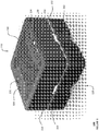
- speakerphone 100 includes top face 110, which comprises five buttons 130, 131, 132, 133, 134. On one side are the pick up call 130 and hang up 131 buttons. On the other side are the volume down 132, mute 133, and volume up 134 buttons.
- the top face 110 also has the speaker grill 140 between the two sets of buttons.
- two side walls 150, 152 are shown with the LED lights 160, 162 at the center of each wall with metal mesh covering the lower half of each side wall. The LEDs may illuminate in different colors to indicate a current operational status of the speakerphone.
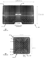
- side wall 152 is shown with a solid upper half 170 and a metal mesh bottom half 172.
- An LED light 180 is shown at the center of the side wall 152, and a cutout for a channel to the cavity is shown at the bottom of the side wall 152.
- the dimensions of the side wall are 120mm wide and 68mm high.
- the cutout for the channel is trapezoidal in shape, having sides that angle slightly outward toward the bottom face of the speakerphone.
- the average width of the cutout is on the order of about 26.5mm, plus or minus 15%.
- the height of the cutout is large enough for the installed cables to fit, such that the bottom face of the speakerphone may be placed on a surface and be in full contact with the surface without pressing on a cable installed in the cavity.
- the height of the cutout is on the order about 7mm, plus or minus 15%.
- the cutout therefore forms a channel to the cavity that is about 26.5mm wide and 7mm deep.
- the cutout may be positioned directly below and centered with the LED light.
- the LED light may have a slightly smaller width than the cutout; for instance, 25mm.
- the particular dimensions discussed herein are merely exemplary, and may be larger or smaller, for instance to accommodate diameters of different sizes of USB, RJ45 and/or power cables.
- top face110 is shown with pick up call 130 and hang up 131 buttons along a first edge 190, and volume down 132, mute 133, and volume up 134 buttons along a second edge 192.
- the buttons may all be the same shape and size, such as a circle with a 12mm diameter as shown in FIGURE 12B .
- the majority of the top face 110 between the first edge 190 and the second edge 192 is covered by a speaker grill 194.
- the speaker grill may have trapezoidal cutouts along a first edge and a second edge, such that the speaker grill partially encloses or otherwise goes around the buttons located on the first edge 190 and the second edge 192 of the top face when installed.
- buttons of the speakerphone may have features that provide tactile feedback to users.
- FIGURE 3 are views of buttons 132, 133, 134 of speakerphone 100.
- Each button of speakerphone 100 has a concave shape and include a raised ring 195 around the button and a raised dot 196 by each button.
- the raised ring 195 and the raised dot 196 allow a user to recognize button location using touch, making it easier for visually impaired users to use the speakerphone.
- the features such as the raised ring and the raised dot may be manufactured as part of the top face of the speakerphone.
- the images of the buttons are shown to be a silkscreen print, such as the plus sign 197 for button 134.
- Each speakerphone in addition to having a speaker and a microphone, also has input buttons, LED lights, and a computing device.
- the computing device may comprise one or more processors and a memory that stores instructions for operation of the speakerphone and other data.
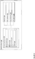
- speakerphone 100 is depicted as having computing device 200 that includes processor(s) 210 and memory 212. Stored in memory 212 are instructions 214 for operation of the speakerphone and data 216.
- Computing device 200 is configured to operate speaker 220, microphone 222, input buttons 224, and LED lights 226.
- the speakerphone may comprise an assembly 500 of a plurality of components, as shown in FIGURE 5 .
- the speakerphone may comprise a top housing structure and a bottom face component.
- Top housing structure 310 comprises an assembly that includes the top face and the plurality of side walls of the speakerphone, leaving an open end. Components such as the speaker, microphone, processor(s), and memory may be assembled within the top housing structure.
- Bottom face component 320 includes an interior side, shown in FIGURE 6A , that is configured to contact and/or couple with components of the top housing structure 310, such as the processor(s).
- Bottom face component 320 also includes an exterior side, shown in FIGURE 6B , that comprises the bottom face of the speakerphone.
- bottom face component 320 closes the open end of the top housing structure 310.
- the assembly may include screws and other fastening means to hold together the plurality of components of the speakerphone.
- the bottom face of the speakerphone includes a cavity that is configured to receive at least one cable connector.
- the cavity may be configured to receive at least one cable connector at or proximate to an inner wall opposite the wall where the cable connector enters the cavity.
- the inner wall may include ports for cable connectors, such as USB plugs, RJ45 plugs, and/or power plugs, that may be positioned in the cavity such that cable connectors may attach to opposite sides and the cables may run parallel to each other in the cavity.
- the cavity may include a rectangular well in the bottom face of the speakerphone.
- the rectangular well may have a first wall, a second wall, a third wall, and a fourth wall.
- the first wall may be parallel and opposite the third wall
- the second wall may be between the first wall and the third wall and may be parallel and opposite the fourth wall.
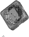
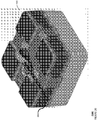
- the cavity includes rectangular well 400, which has first wall 402, second wall 404, third wall 406, and fourth wall 408.
- First wall 402 is parallel and opposite third wall 406, and second wall 404 is between first wall 402 and third wall 406 and is parallel and opposite fourth wall 408.
- the cavity may further include one or more channels between the edge of the bottom face to the cavity.
- the one or more channels may be shallower than the rectangular well.
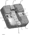
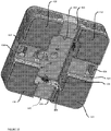
- An attachment means may also be included on the bottom face for connection with a retention bracket to stabilize the speakerphone on a surface. Shown in the perspective views of FIGURES 8-12 is cavity including a rectangular well 400 at the center of the bottom face 120, four channels 422, 424, 426, 428 from the center of each edge of the bottom face 120 to the well 400, and two attachment features 434, 438 carved in two of the channels 424, 428.
- Channels 422, 424, 426, 428 are shaped the same as the cutouts of the side walls of the speakerphone 100, having a trapezoidal shape with sides that angle slightly outward toward bottom face 120 of speakerphone 100.
- the average width of the channel is about 26.5mm, and the depth of the channel is about 7mm.
- the cavity and four channels 422, 424, 426, 428 carve into the bottom face in a cross pattern.
- the remaining portions of the bottom face of the speakerphone may be covered in material that provides vibration damping, such as ethylene propylene diene monomer rubber or cellular rubbers.
- the rest of the bottom face apart from the well, channels, and attachment features comprise base pads.
- the bottom face comprises four base pads 432, 434, 436, 438 located at the corners of the bottom face, interspersed between the four channels 422, 424, 426, 428 that are adapted to receive one or more cables therethrough.
- Base pad 432 is between channels 422 and 424; base pad 434 is between channels 424 and 426; base pad 436 is between channels 426 and 428; and base pad 438 is between channels 428 and 422.
- the base pads 432, 434, 436, 438 of the speakerphone When in use, the base pads 432, 434, 436, 438 of the speakerphone are placed flat against a surface, such as a table, and the clearance between the table and the channels 422, 424, 426, 428 is large enough for installed cables to pass through.
- the base pads may be covered in a vibration damping material, such as cellular rubber.
- a port may be positioned in the cavity such that installation of a cable in a different port in the cavity blocks access to the port.
- ports included in the cavity may include a micro-USB port on a first wall of the cavity, a first RJ45 port positioned next to the micro-USB port on the first wall nearer to the second wall, a barrel power port positioned on the second wall close to the first wall, and a second RJ45 port positioned on the third wall at a greater distance from the second wall than the first RJ45 port.
- the first RJ45 port on the first wall and the barrel power plug on the second wall may be close enough to each other that when an RJ45 cable is inserted in the first RJ45 port, the RJ45 plug blocks access to the barrel power port, and vice versa.
- the well 400 shown in FIGURES 8-12 is configured to receive a plurality of plugs.
- the well walls 402, 404, 406, 408 are deep enough such that installed cable plugs fit underneath the speakerphone 100 so that the speakerphone 100 may be placed on a surface and fully contact the surface.
- the well 400 has a depth of 24.5mm from the bottom face 120 of the speakerphone and/or 17.5mm from the depth of the channels 422, 424, 426, 428.
- First wall 402 includes a micro-USB port 412 and a first RJ45 port 413
- a second wall 404 includes a barrel power port 414
- a third wall 406 includes a second RJ45 port 416
- a fourth wall 408 includes a cable guide 418.
- the distance between the first and third walls and the second and fourth walls may be large enough to accommodate all the maximum number of cables necessary for speakerphone operation.
- the cavity shown in FIGURES 8-12 has distances of about 73.5mm between the first 402 and third 406 walls and about 38.5mm between the second 404 and fourth 408 walls.
- This implementation is able to accommodate a barrel power cable connector, an RJ45 cable connector, and a micro-USB cable connector.
- the cavity may also include guides for at least one cable.
- a cable guide may be included as part of the fourth wall.
- the cable guide may include two openings in the fourth wall and a U-shaped channel cut into the bottom face of the speakerphone between the two openings.
- the U-shaped channel may be shallower than the well.
- the cable guide may be used to coil the micro-USB cable and guide the micro-USB plug to the micro-USB port. The coiling of the micro-USB cable may secure the connection and also divert the micro-USB cable away from an RJ45 cable inserted in the second RJ45 port on the third wall.
- cable guide 418 is included in fourth wall 408.
- Cable guide 418 comprises two openings in fourth wall 408 and a U-shaped channel cut into bottom face 120 to a shallower depth than the well 400 and deeper depth than channels 422, 424, 426, 428.
- cable guide 418 comprises a semicircle-shaped channel.
- the cable guide channel has an inner radius 1302 and an outer radius 1304 greater than the inner radios 1302.
- the inner radius may be about 4.75mm
- the outer radius may be about 10.1mm.
- the cable guide channel also has a width 1306 and a depth 1308.
- the cable guide channel width is about 5-6mm, and the depth is about 14.8mm from the bottom face of the speakerphone or 7.8mm from the channel depth.
- the specific dimensions discussed herein are non-limiting, and may vary, for instance to accommodate different types and diameters of cables.
- the inner and outer radii 1302, 1304 are selected to provide an acceptable cable bending radius, which reduces the likelihood of an electrical break in the wiring of the cable.
- more than one conference speakerphone having the above-described configuration may be connected and used for conducting a given call.
- a plurality of speakerphones may be daisy-chained together, including a master unit, an end unit, and any number of mid units connected between the master unit and the end unit.
- the cavity of each speakerphone includes all ports needed for operation as any of a master unit, an end unit, or a mid unit.
- FIGURES 14A and 14B show views of the bottom face of speakerphone 100 wired for use as a master unit of a string of speakerphones in accordance with aspects of the disclosure.
- the speakerphone 100 is wired with a barrel power plug 1402, 1412, an RJ45 plug 1404, 1414, and a micro-USB plug 1406, 1416.
- the micro-USB cable 1416 is coiled around the cable guide in a loop to better secure the plug in the port. In operation the bottom face is in contact with the table or other surface.
- FIGURES 15A and 15B show views of the bottom face of speakerphone 100 wired for use as a mid unit of a string of speakerphones in accordance with aspects of the disclosure.
- the speakerphone 100 is wired with two RJ45 plugs 1502 and 1504, 1512 and 1514 connected to opposite walls of the cavity of the speakerphone, with portions of the RJ45 cables overlapping in parallel within the cavity.
- One RJ45 cable is for input and the other RJ45 cable is for output.
- the bottom face is in contact with the table or other surface.
- FIGURE 16 shows a view of the bottom face of speakerphone 100 wired for use as an end unit of a string of speakerphones in accordance with aspects of the disclosure.
- the speakerphone 100 is wired with a single RJ45 plug 1602. In operation the bottom face is in contact with the table or other surface.
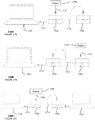
- FIGURES 17A-C are pictorial diagrams of examples of two speakerphones tethered together for conferencing in accordance with aspects of the disclosure.
- speakerphone setup 1700A of an audio source 1702 and two speakerphones configured as described above includes a cable connection 1712 between audio source 1702 and a first speakerphone 1704, for example, via a USB cable, and a cable connection 1714 between first speakerphone 1704 and second speakerphone 1706, for example, via an RJ45 cable.
- a power source 1708 is connected to first speakerphone 1704 using power cable 1716.
- audio source 1702 is a single computer
- first speakerphone 1704 functions as a master unit 1704 since first speakerphone 1704 is directly connected to the audio source
- second speakerphone 1706 functions as an end unit.
- installation of speakerphone set up 1700B includes a cable connection 1712 between audio source 1702 and first speakerphone 1704, for example, via a USB cable, and a cable connection 1714 between first speakerphone 1704 and second speakerphone 1706, for example, via an RJ45 cable.
- a power source 1708 is connected to second speakerphone 1706 via power cable 1716.
- First speakerphone 1704 still functions as a master unit, and second speakerphone 1706 as an end unit.
- FIGURE 17C it is an improper installation 1700C to connect speakerphone setup 1700A or 1700B to a second computer 1720 or other audio or power source.
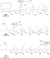
- FIGURES 18A-C are pictorial diagrams of examples of more than two speakerphones tethered together for conferencing in accordance with aspects of the disclosure.
- the speakerphone setup 1800A in FIGURE 18A includes a first speakerphone 1704 with a cable connection 1712 to audio source such as a computer, for example, via a USB cable.
- the plurality of speakerphones 1704, 1706, 1802 are connected one to the next starting from first speakerphone 1704 to second speakerphone 1706, via cable connection 1714, and second speakerphone 1706 to third speakerphone 1802 via cable connection 1812.
- the cable connections 1714, 1812 may be via RJ45 cables.
- the first speakerphone functions as the master unit, the second speakerphone 1706 as the mid unit, and the third speakerphone 1802 as the end unit.
- the power source 1708 is properly installed via power cable 1716 to first speakerphone 1704, the master unit.
- Speakerphone setup 1800B in FIGURE 18B includes setup 1800A with an addition of two additional speakerphones 1804, 1806.
- Cable connection 1814 connects speakerphone 1804 to speakerphone 1802 to continue the string of speakerphones
- cable connection 1816 connects speakerphone 1806 to 1804, making speakerphone 1806 the new end unit of the setup.
- Speakerphone setup 1800C of FIGURE 18C is a variation of speakerphone setup 1800B differing in the location of the connection to power source 1708. As illustrated, power source 1708 is properly installed to speakerphone 1806 via power cable 1716.
- Speakerphone setup 1900 of FIGURE 19 shows a further variation of setup 1800B.
- audio source 1702 is connected to speakerphone 1802, a mid unit, rather than speakerphone 1704, which becomes a second end unit to the string of speakerphones. It is possible to connect the computer to any of the mid units of a string of speakerphones.
- power source 1708 remains connected to speakerphone 1704, supplying power to the other speakerphones in the string, but may alternatively be connected to speakerphone 1806, as shown in FIGURE 18C ..
- a processor in each of the speakerphones may determine whether a given speakerphone is a master unit, mid unit, or an end unit based on detecting which cables are connected to the speakerphone. The processor may then follow instructions stored in the memory of the speakerphone, such as instructions 214 in memory 212, to operate the speakerphone as the determined unit. The processor may also determine whether a given speakerphone has cables improperly connected and provide an indication of the improper connection, for example, using the LED lights 226.
- One mixed audio signal is provided to an audio source, such audio source 1702, and output from the audio source to the full string of speakerphones.
- the full string of speakerphones then operates to provide audio output from every speakerphone in the full string as a single speaker.
- Using multiple speakerphones in this way may provide enough sound to fill a larger room such that call participants may hear the call clearly no matter where they are in the room.
- each speakerphone also has a microphone, such as microphone 222, call participants also may be clearly heard no matter where they are in the room.
- This multiple-speakerphone setup is significantly less costly and provides better audio than traditional conference room systems.
- buttons on each tethered speakerphone are synchronized. For example, pressing the mute button on one speakerphone unit causes all speakerphone units to be muted. Pressing a volume control button on one unit causes the audio volume to be raised or lowered on all units.
- touch input may be received at a given speakerphone in a string of speakerphones connected as disclosed above. Then, the processors in each of the other speakerphones in the string of speakerphones receive instructions based on the touch input in the given speakerphone via the RJ45 cables linking the speakerphones. For instance, in setup 1900, touch input, such as pressing the mute button, may be received at any one of speakerphones 1704, 1706, 1802, 1804, and 1806. In response, all the speakerphones will receive instructions, such as to mute their respective microphones, via the cable connections 1714, 1812, 1814, and 1816.
- the speakerphone may include one or more USB ports at any location on the speakerphone for connection to an audio source.
- a USB port may be on one of the side walls of the speakerphone for ease of access.
- a single speakerphone may be used to conduct a given call.
- the speakerphone setup only requires a USB connection with the audio source.
- FIGURE 20 shows a view of the bottom face of a speakerphone wired for single unit use. As shown, only a USB connection 2002 is used to connect to an audio source.
- the audio source such as a computer, may also serve as the power source for the speakerphone.
- FIGURES 21A and 21B show setups 2100A and 2100B for a speakerphone used as a single unit.
- the speakerphone 1704 is connected to audio source 1702, such as a computer, via a cable connection 1712, such as a USB cable.
- Audio source 1702 may be a type that may serve as both the audio source and a power source, in which case the speakerphone need not be connected to a separate power source, as shown in setup 2100A. However, as shown in setup 2100B, the speakerphone is also properly installed when connected to a separate power source 1708 via power cable 1716.
- the features of the speakerphone described above allows for simple and intuitive design.
- the configuration of the ports in the cavity of the speakerphone not only creates a more efficient use of space since stiff wires are able to lay flat instead of bent at an angle, but the configuration also allows for intuitive and safe installation.
- the speakerphone When used as a mid unit, for example, the speakerphone is not directly connected to a power supply. Also, there is no confusion as to which speakerphone may be used as which unit, since each speakerphone device is configured to work in any position in the chain.
- the button features described above allow for the speakerphone to be used easily by users who are visually impaired.
Landscapes
- Engineering & Computer Science (AREA)
- Signal Processing (AREA)
- Physics & Mathematics (AREA)
- Acoustics & Sound (AREA)
- Telephone Function (AREA)
Claims (15)
- Freisprecheinrichtung (100), umfassend:einen Lautsprecher (220);ein Mikrofon (222); undein Gehäuse (310), das den Lautsprecher (220) und das Mikrofon (222) zumindest teilweise umschließt und Folgendes beinhaltet:eine Oberseite (110), die eine Vielzahl von Eingabeschaltflächen (130, 131, 132, 133, 134) beinhaltet;mindestens eine Seitenwand (150, 152), die eine oder mehrere Leuchten (160, 162) beinhaltet; undeine der Oberseite (110) gegenüberliegende Unterseite (120), wobei die Unterseite (120) einen Hohlraum beinhaltet, wobei der Hohlraum einen Schacht (400) umfasst, der Folgendes aufweist:eine erste Wand (402), die einen ersten Anschluss aufweist,eine zweite Wand (404), die an die erste Wand (402) angrenzt, wobei die zweite Wand (404) einen zweiten Anschluss aufweist,eine dritte Wand (406), die an die zweite Wand (404) angrenzt und parallel zu der ersten Wand (402) ist, wobei die dritte Wand einen dritten Anschluss aufweist, undeine vierte Wand (408), die an die erste Wand (402) und die dritte Wand (406) angrenzt und parallel zu der zweiten Wand (404) ist;wobei der erste Anschluss unzugänglich ist, wenn ein erstes Kabel mit dem zweiten Anschluss verbunden ist, und der zweite Anschluss unzugänglich ist, wenn ein zweites Kabel mit dem ersten Anschluss verbunden ist.
- Freisprecheinrichtung (100) nach Anspruch 1, wobei der Hohlraum ferner zumindest zwei Kanäle (422, 424, 426, 428) umfasst, wobei ein erster Kanal zwischen einer ersten Seitenwand und dem Schacht (400) verläuft und ein zweiter Kanal zwischen einer zweiten Seitenwand und dem Schacht (400) verläuft.
- Freisprecheinrichtung (100) nach Anspruch 2, wobei der Schacht (400) eine erste Tiefe aufweist, die zur Aufnahme eines Steckers des ersten oder zweiten Kabels ausgewählt wird, und wobei die zumindest zwei Kanäle jeweils eine zweite Tiefe aufweisen, die zur Aufnahme eines ersten oder zweiten Kabels darin ausgewählt wird.
- Freisprecheinrichtung (100) nach Anspruch 1, wobei:der erste Anschluss konfiguriert ist, eine Verbindung zu einer zweiten Freisprecheinrichtung einer Vielzahl von Freisprecheinrichtungen aufzubauen,der zweite Anschluss konfiguriert ist, eine Verbindung zu einer Stromquelle aufzubauen; undder dritte Anschluss konfiguriert ist, eine Verbindung zu einer dritten Freisprecheinrichtung der Vielzahl von Freisprecheinrichtungen aufzubauen.
- Freisprecheinrichtung (100) nach Anspruch 1, wobei der erste Anschluss ein RJ45-Anschluss ist und der zweite Anschluss ein Barrel-Stromanschluss ist.
- Freisprecheinrichtung (100) nach Anspruch 5, wobei der RJ45-Anschluss ein erster RJ45-Anschluss ist und die dritte Wand einen dritten Anschluss aufweist, der ein zweiter RJ45-Anschluss ist.
- Freisprecheinrichtung (100) nach Anspruch 6, wobei die erste Wand (402) einen vierten Anschluss aufweist, bei dem es sich um einen Micro-USB-Anschluss handelt, und
wobei die vierte Wand (408) eine Kabelführung für ein Micro-USB-Kabel aufweist. - Anordnung, umfassend:eine Vielzahl von Freisprecheinrichtungen (100) nach Anspruch 1,wobei ein Paar von Freisprecheinrichtungen aus der Vielzahl von Freisprecheinrichtungen konfiguriert ist, eine Verbindung über ein Kabel aufzubauen, das in einem ersten Anschluss einer ersten Freisprecheinrichtung und dem dritten Anschluss einer zweiten Freisprecheinrichtung installiert ist.
- Anordnung nach Anspruch 8, wobei:der erste Anschluss konfiguriert ist, eine Verbindung zu der zweiten Freisprecheinrichtung der Vielzahl von Freisprecheinrichtungen aufzubauen,der zweite Anschluss konfiguriert ist, eine Verbindung zu einer Stromquelle aufzubauen, undder dritte Anschluss konfiguriert ist, eine Verbindung zu einer dritten Freisprecheinrichtung der Vielzahl von Freisprecheinrichtungen aufzubauen.
- Anordnung nach Anspruch 9, wobei:der erste Anschluss ein erster RJ45-Anschluss ist,der zweite Anschluss ein Barrel-Stromanschluss ist, undder dritte Anschluss ein zweiter RJ45-Anschluss ist.
- Anordnung nach Anspruch 10, wobei die erste Wand ferner einen vierten Anschluss beinhaltet, bei dem es sich um einen Micro-USB-Anschluss handelt, und
wobei die vierte Wand eine Kabelführung für ein Micro-USB-Kabel aufweist. - Anordnung nach Anspruch 8, wobei der Hohlraum ferner zumindest zwei Kanäle umfasst, wobei ein erster Kanal zwischen einer ersten Seitenwand und dem Schacht verläuft und ein zweiter Kanal zwischen einer zweiten Seitenwand und dem Schacht verläuft.
- Anordnung nach Anspruch 12, wobei der Schacht eine erste Tiefe aufweist, die zur Aufnahme eines Steckers des ersten oder zweiten Kabels ausgewählt wird, und wobei die zumindest zwei Kanäle jeweils eine zweite Tiefe aufweisen, die zur Aufnahme eines zweiten Kabels darin ausgewählt wird.
- Anordnung nach Anspruch 8, wobei die erste Freisprecheinrichtung der Vielzahl von Freisprecheinrichtungen funktionsfähig ist, wenn sie über den ersten Anschluss der ersten Freisprecheinrichtung mit der zweiten Freisprecheinrichtung der Vielzahl von Freisprecheinrichtungen, über den zweiten Anschluss der ersten Freisprecheinrichtung mit einer Stromquelle und über einen vierten Anschluss der ersten Freisprecheinrichtung mit einer Audioquelle verbunden ist.
- Anordnung nach Anspruch 14, wobei die zweite Freisprecheinrichtung funktionsfähig ist, wenn sie über den dritten Anschluss der zweiten Freisprecheinrichtung mit der ersten Freisprecheinrichtung und über den ersten Anschluss der zweiten Freisprecheinrichtung mit der dritten Freisprecheinrichtung verbunden ist.
Applications Claiming Priority (3)
| Application Number | Priority Date | Filing Date | Title |
|---|---|---|---|
| US201662320153P | 2016-04-08 | 2016-04-08 | |
| US15/370,148 US9854080B2 (en) | 2016-04-08 | 2016-12-06 | Speakerphone configuration for conferencing |
| PCT/US2016/065850 WO2017176326A1 (en) | 2016-04-08 | 2016-12-09 | Speakerphone configuration for conferencing |
Publications (2)
| Publication Number | Publication Date |
|---|---|
| EP3440825A1 EP3440825A1 (de) | 2019-02-13 |
| EP3440825B1 true EP3440825B1 (de) | 2019-08-07 |
Family
ID=57758710
Family Applications (1)
| Application Number | Title | Priority Date | Filing Date |
|---|---|---|---|
| EP16823388.0A Active EP3440825B1 (de) | 2016-04-08 | 2016-12-09 | Freisprechtelefonkonfiguration für konferenzen |
Country Status (6)
| Country | Link |
|---|---|
| US (3) | US9854080B2 (de) |
| EP (1) | EP3440825B1 (de) |
| CN (3) | CN206743545U (de) |
| DE (2) | DE102016125499A1 (de) |
| GB (2) | GB2579874B (de) |
| WO (1) | WO2017176326A1 (de) |
Families Citing this family (5)
| Publication number | Priority date | Publication date | Assignee | Title |
|---|---|---|---|---|
| US9641919B1 (en) | 2014-09-30 | 2017-05-02 | Amazon Technologies, Inc. | Audio assemblies for electronic devices |
| US9854080B2 (en) | 2016-04-08 | 2017-12-26 | Google Llc | Speakerphone configuration for conferencing |
| US10887467B2 (en) | 2018-11-20 | 2021-01-05 | Shure Acquisition Holdings, Inc. | System and method for distributed call processing and audio reinforcement in conferencing environments |
| US11653993B2 (en) * | 2019-09-18 | 2023-05-23 | Grigory Goldberg | Compartmentalized medical surgical kit system |
| US11449114B2 (en) * | 2020-03-25 | 2022-09-20 | Amazon Technologies, Inc. | Voice activated device with integrated heatsink and speaker |
Family Cites Families (28)
| Publication number | Priority date | Publication date | Assignee | Title |
|---|---|---|---|---|
| US4620317A (en) | 1984-04-05 | 1986-10-28 | Shure Brothers, Inc. | Tabletop speaker assembly |
| US5041009A (en) | 1987-08-31 | 1991-08-20 | Amp Incorporated | Daisy chain connector and method |
| US5329620A (en) | 1992-03-25 | 1994-07-12 | One Touch Systems, Inc. | Daisy chainable voice-data terminal |
| US5369701A (en) * | 1992-10-28 | 1994-11-29 | At&T Corp. | Compact loudspeaker assembly |
| US5226076A (en) * | 1993-02-28 | 1993-07-06 | At&T Bell Laboratories | Directional microphone assembly |
| US5561737A (en) * | 1994-05-09 | 1996-10-01 | Lucent Technologies Inc. | Voice actuated switching system |
| KR970010253B1 (en) * | 1995-05-29 | 1997-06-23 | Daewoo Electronics Co Ltd | Speaker system |
| US6016346A (en) * | 1997-10-21 | 2000-01-18 | 3Com Corporation | Low-profile speakerphone with downward oriented microphone configuration |
| US6104807A (en) * | 1998-02-23 | 2000-08-15 | Nortel Networks Corporation | Display-based add-on module |
| US7339605B2 (en) * | 2004-04-16 | 2008-03-04 | Polycom, Inc. | Conference link between a speakerphone and a video conference unit |
| US8064969B2 (en) * | 2003-08-15 | 2011-11-22 | Avaya Inc. | Method and apparatus for combined wired/wireless pop-out speakerphone microphone |
| US7937117B2 (en) * | 2003-11-17 | 2011-05-03 | Gn Netcom A/S | Portable speakerphone with pivoting microphone boom |
| US8031853B2 (en) | 2004-06-02 | 2011-10-04 | Clearone Communications, Inc. | Multi-pod conference systems |
| US20060132595A1 (en) | 2004-10-15 | 2006-06-22 | Kenoyer Michael L | Speakerphone supporting video and audio features |
| US7646862B2 (en) * | 2005-05-24 | 2010-01-12 | Polycom, Inc. | Speakerphone with a novel loudspeaker placement |
| US7925004B2 (en) * | 2006-04-27 | 2011-04-12 | Plantronics, Inc. | Speakerphone with downfiring speaker and directional microphones |
| US20080278894A1 (en) * | 2007-05-11 | 2008-11-13 | Miradia Inc. | Docking station for projection display applications |
| US8379823B2 (en) | 2008-04-07 | 2013-02-19 | Polycom, Inc. | Distributed bridging |
| US8199958B2 (en) * | 2008-05-22 | 2012-06-12 | Robert Bosch Gmbh | Battery charging jobsite audio apparatus |
| US7946866B2 (en) | 2008-08-28 | 2011-05-24 | Abbott Diabetes Care Inc. | Apparatus for preventing electrical shock in devices |
| US20100318203A1 (en) * | 2009-06-16 | 2010-12-16 | Brooks Mitchell T | Audio Recording Apparatus |
| JP2013062773A (ja) * | 2011-09-15 | 2013-04-04 | Onkyo Corp | 音響再生装置およびこれを含む立体映像再生装置 |
| CN202617347U (zh) * | 2012-03-30 | 2012-12-19 | 巍智产品设计有限公司 | 手持式扩音装置 |
| EP3005669B1 (de) * | 2013-06-06 | 2019-04-17 | Dolby Laboratories Licensing Corporation | Beleuchtung für audiovorrichtungen |
| US9927837B2 (en) * | 2013-07-03 | 2018-03-27 | Pucline, Llc | Electrical power supplying system having an electrical power supplying docking station with a multi-function module for use in diverse environments |
| JP6426488B2 (ja) * | 2015-01-30 | 2018-11-21 | セイコーインスツル株式会社 | プリンタ及び制御回路 |
| US9479627B1 (en) * | 2015-12-29 | 2016-10-25 | Gn Audio A/S | Desktop speakerphone |
| US9854080B2 (en) * | 2016-04-08 | 2017-12-26 | Google Llc | Speakerphone configuration for conferencing |
-
2016
- 2016-12-06 US US15/370,148 patent/US9854080B2/en active Active
- 2016-12-09 EP EP16823388.0A patent/EP3440825B1/de active Active
- 2016-12-09 WO PCT/US2016/065850 patent/WO2017176326A1/en not_active Ceased
- 2016-12-22 DE DE102016125499.1A patent/DE102016125499A1/de active Pending
- 2016-12-22 GB GB1906133.2A patent/GB2579874B/en active Active
- 2016-12-22 DE DE202016008139.0U patent/DE202016008139U1/de active Active
- 2016-12-22 GB GB1621996.6A patent/GB2549162B/en active Active
- 2016-12-27 CN CN201621454848.2U patent/CN206743545U/zh not_active Withdrawn - After Issue
- 2016-12-27 CN CN201721536476.2U patent/CN208079391U/zh active Active
- 2016-12-27 CN CN201611227716.0A patent/CN107277727B/zh active Active
-
2017
- 2017-11-15 US US15/813,721 patent/US10367930B2/en active Active
-
2019
- 2019-06-11 US US16/437,616 patent/US10855827B2/en active Active
Non-Patent Citations (1)
| Title |
|---|
| None * |
Also Published As
| Publication number | Publication date |
|---|---|
| US10855827B2 (en) | 2020-12-01 |
| GB2549162A (en) | 2017-10-11 |
| US9854080B2 (en) | 2017-12-26 |
| CN206743545U (zh) | 2017-12-12 |
| EP3440825A1 (de) | 2019-02-13 |
| US20180109663A1 (en) | 2018-04-19 |
| GB2549162B (en) | 2019-06-19 |
| DE202016008139U1 (de) | 2017-05-29 |
| WO2017176326A1 (en) | 2017-10-12 |
| US20200021677A1 (en) | 2020-01-16 |
| US10367930B2 (en) | 2019-07-30 |
| CN107277727A (zh) | 2017-10-20 |
| US20170295275A1 (en) | 2017-10-12 |
| GB201906133D0 (en) | 2019-06-12 |
| GB2579874A (en) | 2020-07-08 |
| CN208079391U (zh) | 2018-11-09 |
| CN107277727B (zh) | 2018-12-04 |
| GB201621996D0 (en) | 2017-02-08 |
| DE102016125499A1 (de) | 2017-10-12 |
| GB2579874B (en) | 2020-12-23 |
Similar Documents
| Publication | Publication Date | Title |
|---|---|---|
| US10855827B2 (en) | Speakerphone configuration for conferencing | |
| US11297417B2 (en) | Voice controlled assistant | |
| EP3942841B1 (de) | Elektronische vorrichtung | |
| EP2269275B1 (de) | Verbinder | |
| CN106253012A (zh) | 一种转换器及带有该转换器的多功能充电音频线 | |
| EP2962447B1 (de) | Tragbares radio mit zusätzlicher schnittstelle | |
| US12468503B1 (en) | Sound card | |
| KR200338342Y1 (ko) | 주변장치와 연결되는 커넥터를 키보드에 내장한 개인용컴퓨터 시스템 | |
| CN214205832U (zh) | 一种新型耳机 | |
| KR200212502Y1 (ko) | 컴퓨터본체의 전면에 설치된 신호선제어장치 | |
| KR100392124B1 (ko) | 컴퓨터본체의 전면에 설치된 신호선제어장치 | |
| KR200374766Y1 (ko) | 무선통신용 복합기 | |
| KR20060056742A (ko) | 무선통신용 복합기 | |
| KR200359332Y1 (ko) | 전화기용 핸즈프리 어댑터 | |
| KR20000030275A (ko) | 컴퓨터용 멀티 커넥터 | |
| KR20090007913U (ko) | 휴대 단말기용 이어 마이크로폰 장치를 위한 젠더 | |
| KR200258449Y1 (ko) | 다기능스피커 | |
| WO2001084288A1 (en) | Computer having separate input/output box | |
| KR19980066473U (ko) | 다기능 플러그 | |
| KR20000021070U (ko) | 전자기기 통합셋업 박스 |
Legal Events
| Date | Code | Title | Description |
|---|---|---|---|
| STAA | Information on the status of an ep patent application or granted ep patent |
Free format text: STATUS: UNKNOWN |
|
| STAA | Information on the status of an ep patent application or granted ep patent |
Free format text: STATUS: THE INTERNATIONAL PUBLICATION HAS BEEN MADE |
|
| PUAI | Public reference made under article 153(3) epc to a published international application that has entered the european phase |
Free format text: ORIGINAL CODE: 0009012 |
|
| STAA | Information on the status of an ep patent application or granted ep patent |
Free format text: STATUS: REQUEST FOR EXAMINATION WAS MADE |
|
| 17P | Request for examination filed |
Effective date: 20180629 |
|
| AK | Designated contracting states |
Kind code of ref document: A1 Designated state(s): AL AT BE BG CH CY CZ DE DK EE ES FI FR GB GR HR HU IE IS IT LI LT LU LV MC MK MT NL NO PL PT RO RS SE SI SK SM TR |
|
| AX | Request for extension of the european patent |
Extension state: BA ME |
|
| GRAP | Despatch of communication of intention to grant a patent |
Free format text: ORIGINAL CODE: EPIDOSNIGR1 |
|
| STAA | Information on the status of an ep patent application or granted ep patent |
Free format text: STATUS: GRANT OF PATENT IS INTENDED |
|
| RIC1 | Information provided on ipc code assigned before grant |
Ipc: H04M 1/247 20060101ALI20190123BHEP Ipc: H04M 1/60 20060101AFI20190123BHEP Ipc: H04M 1/62 20060101ALI20190123BHEP |
|
| INTG | Intention to grant announced |
Effective date: 20190222 |
|
| GRAS | Grant fee paid |
Free format text: ORIGINAL CODE: EPIDOSNIGR3 |
|
| GRAA | (expected) grant |
Free format text: ORIGINAL CODE: 0009210 |
|
| STAA | Information on the status of an ep patent application or granted ep patent |
Free format text: STATUS: THE PATENT HAS BEEN GRANTED |
|
| DAV | Request for validation of the european patent (deleted) | ||
| DAX | Request for extension of the european patent (deleted) | ||
| AK | Designated contracting states |
Kind code of ref document: B1 Designated state(s): AL AT BE BG CH CY CZ DE DK EE ES FI FR GB GR HR HU IE IS IT LI LT LU LV MC MK MT NL NO PL PT RO RS SE SI SK SM TR |
|
| REG | Reference to a national code |
Ref country code: GB Ref legal event code: FG4D |
|
| REG | Reference to a national code |
Ref country code: CH Ref legal event code: EP Ref country code: AT Ref legal event code: REF Ref document number: 1165628 Country of ref document: AT Kind code of ref document: T Effective date: 20190815 |
|
| REG | Reference to a national code |
Ref country code: DE Ref legal event code: R096 Ref document number: 602016018381 Country of ref document: DE |
|
| REG | Reference to a national code |
Ref country code: IE Ref legal event code: FG4D |
|
| REG | Reference to a national code |
Ref country code: NL Ref legal event code: FP |
|
| REG | Reference to a national code |
Ref country code: LT Ref legal event code: MG4D |
|
| PG25 | Lapsed in a contracting state [announced via postgrant information from national office to epo] |
Ref country code: PT Free format text: LAPSE BECAUSE OF FAILURE TO SUBMIT A TRANSLATION OF THE DESCRIPTION OR TO PAY THE FEE WITHIN THE PRESCRIBED TIME-LIMIT Effective date: 20191209 Ref country code: BG Free format text: LAPSE BECAUSE OF FAILURE TO SUBMIT A TRANSLATION OF THE DESCRIPTION OR TO PAY THE FEE WITHIN THE PRESCRIBED TIME-LIMIT Effective date: 20191107 Ref country code: HR Free format text: LAPSE BECAUSE OF FAILURE TO SUBMIT A TRANSLATION OF THE DESCRIPTION OR TO PAY THE FEE WITHIN THE PRESCRIBED TIME-LIMIT Effective date: 20190807 Ref country code: LT Free format text: LAPSE BECAUSE OF FAILURE TO SUBMIT A TRANSLATION OF THE DESCRIPTION OR TO PAY THE FEE WITHIN THE PRESCRIBED TIME-LIMIT Effective date: 20190807 Ref country code: NO Free format text: LAPSE BECAUSE OF FAILURE TO SUBMIT A TRANSLATION OF THE DESCRIPTION OR TO PAY THE FEE WITHIN THE PRESCRIBED TIME-LIMIT Effective date: 20191107 Ref country code: FI Free format text: LAPSE BECAUSE OF FAILURE TO SUBMIT A TRANSLATION OF THE DESCRIPTION OR TO PAY THE FEE WITHIN THE PRESCRIBED TIME-LIMIT Effective date: 20190807 Ref country code: SE Free format text: LAPSE BECAUSE OF FAILURE TO SUBMIT A TRANSLATION OF THE DESCRIPTION OR TO PAY THE FEE WITHIN THE PRESCRIBED TIME-LIMIT Effective date: 20190807 |
|
| REG | Reference to a national code |
Ref country code: AT Ref legal event code: MK05 Ref document number: 1165628 Country of ref document: AT Kind code of ref document: T Effective date: 20190807 |
|
| PG25 | Lapsed in a contracting state [announced via postgrant information from national office to epo] |
Ref country code: GR Free format text: LAPSE BECAUSE OF FAILURE TO SUBMIT A TRANSLATION OF THE DESCRIPTION OR TO PAY THE FEE WITHIN THE PRESCRIBED TIME-LIMIT Effective date: 20191108 Ref country code: IS Free format text: LAPSE BECAUSE OF FAILURE TO SUBMIT A TRANSLATION OF THE DESCRIPTION OR TO PAY THE FEE WITHIN THE PRESCRIBED TIME-LIMIT Effective date: 20191207 Ref country code: RS Free format text: LAPSE BECAUSE OF FAILURE TO SUBMIT A TRANSLATION OF THE DESCRIPTION OR TO PAY THE FEE WITHIN THE PRESCRIBED TIME-LIMIT Effective date: 20190807 Ref country code: LV Free format text: LAPSE BECAUSE OF FAILURE TO SUBMIT A TRANSLATION OF THE DESCRIPTION OR TO PAY THE FEE WITHIN THE PRESCRIBED TIME-LIMIT Effective date: 20190807 Ref country code: ES Free format text: LAPSE BECAUSE OF FAILURE TO SUBMIT A TRANSLATION OF THE DESCRIPTION OR TO PAY THE FEE WITHIN THE PRESCRIBED TIME-LIMIT Effective date: 20190807 Ref country code: AL Free format text: LAPSE BECAUSE OF FAILURE TO SUBMIT A TRANSLATION OF THE DESCRIPTION OR TO PAY THE FEE WITHIN THE PRESCRIBED TIME-LIMIT Effective date: 20190807 |
|
| PG25 | Lapsed in a contracting state [announced via postgrant information from national office to epo] |
Ref country code: TR Free format text: LAPSE BECAUSE OF FAILURE TO SUBMIT A TRANSLATION OF THE DESCRIPTION OR TO PAY THE FEE WITHIN THE PRESCRIBED TIME-LIMIT Effective date: 20190807 |
|
| PG25 | Lapsed in a contracting state [announced via postgrant information from national office to epo] |
Ref country code: IT Free format text: LAPSE BECAUSE OF FAILURE TO SUBMIT A TRANSLATION OF THE DESCRIPTION OR TO PAY THE FEE WITHIN THE PRESCRIBED TIME-LIMIT Effective date: 20190807 Ref country code: RO Free format text: LAPSE BECAUSE OF FAILURE TO SUBMIT A TRANSLATION OF THE DESCRIPTION OR TO PAY THE FEE WITHIN THE PRESCRIBED TIME-LIMIT Effective date: 20190807 Ref country code: EE Free format text: LAPSE BECAUSE OF FAILURE TO SUBMIT A TRANSLATION OF THE DESCRIPTION OR TO PAY THE FEE WITHIN THE PRESCRIBED TIME-LIMIT Effective date: 20190807 Ref country code: DK Free format text: LAPSE BECAUSE OF FAILURE TO SUBMIT A TRANSLATION OF THE DESCRIPTION OR TO PAY THE FEE WITHIN THE PRESCRIBED TIME-LIMIT Effective date: 20190807 Ref country code: AT Free format text: LAPSE BECAUSE OF FAILURE TO SUBMIT A TRANSLATION OF THE DESCRIPTION OR TO PAY THE FEE WITHIN THE PRESCRIBED TIME-LIMIT Effective date: 20190807 Ref country code: PL Free format text: LAPSE BECAUSE OF FAILURE TO SUBMIT A TRANSLATION OF THE DESCRIPTION OR TO PAY THE FEE WITHIN THE PRESCRIBED TIME-LIMIT Effective date: 20190807 |
|
| PG25 | Lapsed in a contracting state [announced via postgrant information from national office to epo] |
Ref country code: CZ Free format text: LAPSE BECAUSE OF FAILURE TO SUBMIT A TRANSLATION OF THE DESCRIPTION OR TO PAY THE FEE WITHIN THE PRESCRIBED TIME-LIMIT Effective date: 20190807 Ref country code: SK Free format text: LAPSE BECAUSE OF FAILURE TO SUBMIT A TRANSLATION OF THE DESCRIPTION OR TO PAY THE FEE WITHIN THE PRESCRIBED TIME-LIMIT Effective date: 20190807 Ref country code: SM Free format text: LAPSE BECAUSE OF FAILURE TO SUBMIT A TRANSLATION OF THE DESCRIPTION OR TO PAY THE FEE WITHIN THE PRESCRIBED TIME-LIMIT Effective date: 20190807 Ref country code: IS Free format text: LAPSE BECAUSE OF FAILURE TO SUBMIT A TRANSLATION OF THE DESCRIPTION OR TO PAY THE FEE WITHIN THE PRESCRIBED TIME-LIMIT Effective date: 20200224 |
|
| REG | Reference to a national code |
Ref country code: DE Ref legal event code: R097 Ref document number: 602016018381 Country of ref document: DE |
|
| PLBE | No opposition filed within time limit |
Free format text: ORIGINAL CODE: 0009261 |
|
| STAA | Information on the status of an ep patent application or granted ep patent |
Free format text: STATUS: NO OPPOSITION FILED WITHIN TIME LIMIT |
|
| PG2D | Information on lapse in contracting state deleted |
Ref country code: IS |
|
| REG | Reference to a national code |
Ref country code: CH Ref legal event code: PL |
|
| 26N | No opposition filed |
Effective date: 20200603 |
|
| REG | Reference to a national code |
Ref country code: BE Ref legal event code: MM Effective date: 20191231 |
|
| PG25 | Lapsed in a contracting state [announced via postgrant information from national office to epo] |
Ref country code: MC Free format text: LAPSE BECAUSE OF FAILURE TO SUBMIT A TRANSLATION OF THE DESCRIPTION OR TO PAY THE FEE WITHIN THE PRESCRIBED TIME-LIMIT Effective date: 20190807 |
|
| PG25 | Lapsed in a contracting state [announced via postgrant information from national office to epo] |
Ref country code: IE Free format text: LAPSE BECAUSE OF NON-PAYMENT OF DUE FEES Effective date: 20191209 Ref country code: LU Free format text: LAPSE BECAUSE OF NON-PAYMENT OF DUE FEES Effective date: 20191209 Ref country code: FR Free format text: LAPSE BECAUSE OF NON-PAYMENT OF DUE FEES Effective date: 20191231 |
|
| PG25 | Lapsed in a contracting state [announced via postgrant information from national office to epo] |
Ref country code: LI Free format text: LAPSE BECAUSE OF NON-PAYMENT OF DUE FEES Effective date: 20191231 Ref country code: CH Free format text: LAPSE BECAUSE OF NON-PAYMENT OF DUE FEES Effective date: 20191231 Ref country code: BE Free format text: LAPSE BECAUSE OF NON-PAYMENT OF DUE FEES Effective date: 20191231 |
|
| PG25 | Lapsed in a contracting state [announced via postgrant information from national office to epo] |
Ref country code: CY Free format text: LAPSE BECAUSE OF FAILURE TO SUBMIT A TRANSLATION OF THE DESCRIPTION OR TO PAY THE FEE WITHIN THE PRESCRIBED TIME-LIMIT Effective date: 20190807 |
|
| PG25 | Lapsed in a contracting state [announced via postgrant information from national office to epo] |
Ref country code: HU Free format text: LAPSE BECAUSE OF FAILURE TO SUBMIT A TRANSLATION OF THE DESCRIPTION OR TO PAY THE FEE WITHIN THE PRESCRIBED TIME-LIMIT; INVALID AB INITIO Effective date: 20161209 Ref country code: MT Free format text: LAPSE BECAUSE OF FAILURE TO SUBMIT A TRANSLATION OF THE DESCRIPTION OR TO PAY THE FEE WITHIN THE PRESCRIBED TIME-LIMIT Effective date: 20190807 |
|
| PG25 | Lapsed in a contracting state [announced via postgrant information from national office to epo] |
Ref country code: SI Free format text: LAPSE BECAUSE OF FAILURE TO SUBMIT A TRANSLATION OF THE DESCRIPTION OR TO PAY THE FEE WITHIN THE PRESCRIBED TIME-LIMIT Effective date: 20190807 |
|
| PG25 | Lapsed in a contracting state [announced via postgrant information from national office to epo] |
Ref country code: MK Free format text: LAPSE BECAUSE OF FAILURE TO SUBMIT A TRANSLATION OF THE DESCRIPTION OR TO PAY THE FEE WITHIN THE PRESCRIBED TIME-LIMIT Effective date: 20190807 |
|
| P01 | Opt-out of the competence of the unified patent court (upc) registered |
Effective date: 20230506 |
|
| PGFP | Annual fee paid to national office [announced via postgrant information from national office to epo] |
Ref country code: NL Payment date: 20241226 Year of fee payment: 9 |
|
| PGFP | Annual fee paid to national office [announced via postgrant information from national office to epo] |
Ref country code: GB Payment date: 20241227 Year of fee payment: 9 |
|
| PGFP | Annual fee paid to national office [announced via postgrant information from national office to epo] |
Ref country code: DE Payment date: 20241227 Year of fee payment: 9 |