EP3440733B1 - Liquid level sensor for battery monitoring systems - Google Patents
Liquid level sensor for battery monitoring systems Download PDFInfo
- Publication number
- EP3440733B1 EP3440733B1 EP16895728.0A EP16895728A EP3440733B1 EP 3440733 B1 EP3440733 B1 EP 3440733B1 EP 16895728 A EP16895728 A EP 16895728A EP 3440733 B1 EP3440733 B1 EP 3440733B1
- Authority
- EP
- European Patent Office
- Prior art keywords
- array
- electrode
- battery
- liquid level
- probe
- Prior art date
- Legal status (The legal status is an assumption and is not a legal conclusion. Google has not performed a legal analysis and makes no representation as to the accuracy of the status listed.)
- Active
Links
- 239000007788 liquid Substances 0.000 title claims description 102
- 238000012544 monitoring process Methods 0.000 title claims description 10
- 239000000523 sample Substances 0.000 claims description 45
- 239000003792 electrolyte Substances 0.000 claims description 22
- 239000011244 liquid electrolyte Substances 0.000 claims description 19
- 238000000034 method Methods 0.000 claims description 17
- XLYOFNOQVPJJNP-UHFFFAOYSA-N water Substances O XLYOFNOQVPJJNP-UHFFFAOYSA-N 0.000 claims description 14
- 238000004891 communication Methods 0.000 claims description 12
- 230000008878 coupling Effects 0.000 claims description 10
- 238000010168 coupling process Methods 0.000 claims description 10
- 238000005859 coupling reaction Methods 0.000 claims description 10
- 230000004044 response Effects 0.000 claims description 6
- 238000003780 insertion Methods 0.000 claims 1
- 230000037431 insertion Effects 0.000 claims 1
- 230000008859 change Effects 0.000 description 9
- 239000012530 fluid Substances 0.000 description 9
- 239000002253 acid Substances 0.000 description 8
- 238000010586 diagram Methods 0.000 description 7
- 239000008151 electrolyte solution Substances 0.000 description 7
- 101150108558 PAD1 gene Proteins 0.000 description 5
- 238000005259 measurement Methods 0.000 description 5
- 238000003487 electrochemical reaction Methods 0.000 description 3
- 238000012546 transfer Methods 0.000 description 3
- QAOWNCQODCNURD-UHFFFAOYSA-N Sulfuric acid Chemical compound OS(O)(=O)=O QAOWNCQODCNURD-UHFFFAOYSA-N 0.000 description 2
- 238000006243 chemical reaction Methods 0.000 description 2
- 230000007423 decrease Effects 0.000 description 2
- 238000007789 sealing Methods 0.000 description 2
- 239000000758 substrate Substances 0.000 description 2
- RYGMFSIKBFXOCR-UHFFFAOYSA-N Copper Chemical compound [Cu] RYGMFSIKBFXOCR-UHFFFAOYSA-N 0.000 description 1
- UFHFLCQGNIYNRP-UHFFFAOYSA-N Hydrogen Chemical compound [H][H] UFHFLCQGNIYNRP-UHFFFAOYSA-N 0.000 description 1
- 240000007320 Pinus strobus Species 0.000 description 1
- 230000004075 alteration Effects 0.000 description 1
- QVGXLLKOCUKJST-UHFFFAOYSA-N atomic oxygen Chemical compound [O] QVGXLLKOCUKJST-UHFFFAOYSA-N 0.000 description 1
- 238000009529 body temperature measurement Methods 0.000 description 1
- 239000004020 conductor Substances 0.000 description 1
- 229910052802 copper Inorganic materials 0.000 description 1
- 239000010949 copper Substances 0.000 description 1
- 230000007797 corrosion Effects 0.000 description 1
- 238000005260 corrosion Methods 0.000 description 1
- 230000001419 dependent effect Effects 0.000 description 1
- 238000007599 discharging Methods 0.000 description 1
- 230000008020 evaporation Effects 0.000 description 1
- 238000001704 evaporation Methods 0.000 description 1
- 230000005284 excitation Effects 0.000 description 1
- 239000001257 hydrogen Substances 0.000 description 1
- 229910052739 hydrogen Inorganic materials 0.000 description 1
- 239000001301 oxygen Substances 0.000 description 1
- 229910052760 oxygen Inorganic materials 0.000 description 1
- 238000004806 packaging method and process Methods 0.000 description 1
- 239000000126 substance Substances 0.000 description 1
- 238000013022 venting Methods 0.000 description 1
Images






Classifications
-
- H—ELECTRICITY
- H01—ELECTRIC ELEMENTS
- H01M—PROCESSES OR MEANS, e.g. BATTERIES, FOR THE DIRECT CONVERSION OF CHEMICAL ENERGY INTO ELECTRICAL ENERGY
- H01M10/00—Secondary cells; Manufacture thereof
- H01M10/42—Methods or arrangements for servicing or maintenance of secondary cells or secondary half-cells
- H01M10/48—Accumulators combined with arrangements for measuring, testing or indicating the condition of cells, e.g. the level or density of the electrolyte
- H01M10/484—Accumulators combined with arrangements for measuring, testing or indicating the condition of cells, e.g. the level or density of the electrolyte for measuring electrolyte level, electrolyte density or electrolyte conductivity
-
- G—PHYSICS
- G01—MEASURING; TESTING
- G01F—MEASURING VOLUME, VOLUME FLOW, MASS FLOW OR LIQUID LEVEL; METERING BY VOLUME
- G01F23/00—Indicating or measuring liquid level or level of fluent solid material, e.g. indicating in terms of volume or indicating by means of an alarm
- G01F23/22—Indicating or measuring liquid level or level of fluent solid material, e.g. indicating in terms of volume or indicating by means of an alarm by measuring physical variables, other than linear dimensions, pressure or weight, dependent on the level to be measured, e.g. by difference of heat transfer of steam or water
- G01F23/26—Indicating or measuring liquid level or level of fluent solid material, e.g. indicating in terms of volume or indicating by means of an alarm by measuring physical variables, other than linear dimensions, pressure or weight, dependent on the level to be measured, e.g. by difference of heat transfer of steam or water by measuring variations of capacity or inductance of capacitors or inductors arising from the presence of liquid or fluent solid material in the electric or electromagnetic fields
- G01F23/263—Indicating or measuring liquid level or level of fluent solid material, e.g. indicating in terms of volume or indicating by means of an alarm by measuring physical variables, other than linear dimensions, pressure or weight, dependent on the level to be measured, e.g. by difference of heat transfer of steam or water by measuring variations of capacity or inductance of capacitors or inductors arising from the presence of liquid or fluent solid material in the electric or electromagnetic fields by measuring variations in capacitance of capacitors
-
- G—PHYSICS
- G01—MEASURING; TESTING
- G01F—MEASURING VOLUME, VOLUME FLOW, MASS FLOW OR LIQUID LEVEL; METERING BY VOLUME
- G01F23/00—Indicating or measuring liquid level or level of fluent solid material, e.g. indicating in terms of volume or indicating by means of an alarm
- G01F23/22—Indicating or measuring liquid level or level of fluent solid material, e.g. indicating in terms of volume or indicating by means of an alarm by measuring physical variables, other than linear dimensions, pressure or weight, dependent on the level to be measured, e.g. by difference of heat transfer of steam or water
- G01F23/26—Indicating or measuring liquid level or level of fluent solid material, e.g. indicating in terms of volume or indicating by means of an alarm by measuring physical variables, other than linear dimensions, pressure or weight, dependent on the level to be measured, e.g. by difference of heat transfer of steam or water by measuring variations of capacity or inductance of capacitors or inductors arising from the presence of liquid or fluent solid material in the electric or electromagnetic fields
- G01F23/263—Indicating or measuring liquid level or level of fluent solid material, e.g. indicating in terms of volume or indicating by means of an alarm by measuring physical variables, other than linear dimensions, pressure or weight, dependent on the level to be measured, e.g. by difference of heat transfer of steam or water by measuring variations of capacity or inductance of capacitors or inductors arising from the presence of liquid or fluent solid material in the electric or electromagnetic fields by measuring variations in capacitance of capacitors
- G01F23/265—Indicating or measuring liquid level or level of fluent solid material, e.g. indicating in terms of volume or indicating by means of an alarm by measuring physical variables, other than linear dimensions, pressure or weight, dependent on the level to be measured, e.g. by difference of heat transfer of steam or water by measuring variations of capacity or inductance of capacitors or inductors arising from the presence of liquid or fluent solid material in the electric or electromagnetic fields by measuring variations in capacitance of capacitors for discrete levels
-
- G—PHYSICS
- G01—MEASURING; TESTING
- G01F—MEASURING VOLUME, VOLUME FLOW, MASS FLOW OR LIQUID LEVEL; METERING BY VOLUME
- G01F23/00—Indicating or measuring liquid level or level of fluent solid material, e.g. indicating in terms of volume or indicating by means of an alarm
- G01F23/22—Indicating or measuring liquid level or level of fluent solid material, e.g. indicating in terms of volume or indicating by means of an alarm by measuring physical variables, other than linear dimensions, pressure or weight, dependent on the level to be measured, e.g. by difference of heat transfer of steam or water
- G01F23/26—Indicating or measuring liquid level or level of fluent solid material, e.g. indicating in terms of volume or indicating by means of an alarm by measuring physical variables, other than linear dimensions, pressure or weight, dependent on the level to be measured, e.g. by difference of heat transfer of steam or water by measuring variations of capacity or inductance of capacitors or inductors arising from the presence of liquid or fluent solid material in the electric or electromagnetic fields
- G01F23/263—Indicating or measuring liquid level or level of fluent solid material, e.g. indicating in terms of volume or indicating by means of an alarm by measuring physical variables, other than linear dimensions, pressure or weight, dependent on the level to be measured, e.g. by difference of heat transfer of steam or water by measuring variations of capacity or inductance of capacitors or inductors arising from the presence of liquid or fluent solid material in the electric or electromagnetic fields by measuring variations in capacitance of capacitors
- G01F23/266—Indicating or measuring liquid level or level of fluent solid material, e.g. indicating in terms of volume or indicating by means of an alarm by measuring physical variables, other than linear dimensions, pressure or weight, dependent on the level to be measured, e.g. by difference of heat transfer of steam or water by measuring variations of capacity or inductance of capacitors or inductors arising from the presence of liquid or fluent solid material in the electric or electromagnetic fields by measuring variations in capacitance of capacitors measuring circuits therefor
-
- G—PHYSICS
- G01—MEASURING; TESTING
- G01F—MEASURING VOLUME, VOLUME FLOW, MASS FLOW OR LIQUID LEVEL; METERING BY VOLUME
- G01F23/00—Indicating or measuring liquid level or level of fluent solid material, e.g. indicating in terms of volume or indicating by means of an alarm
- G01F23/22—Indicating or measuring liquid level or level of fluent solid material, e.g. indicating in terms of volume or indicating by means of an alarm by measuring physical variables, other than linear dimensions, pressure or weight, dependent on the level to be measured, e.g. by difference of heat transfer of steam or water
- G01F23/26—Indicating or measuring liquid level or level of fluent solid material, e.g. indicating in terms of volume or indicating by means of an alarm by measuring physical variables, other than linear dimensions, pressure or weight, dependent on the level to be measured, e.g. by difference of heat transfer of steam or water by measuring variations of capacity or inductance of capacitors or inductors arising from the presence of liquid or fluent solid material in the electric or electromagnetic fields
- G01F23/263—Indicating or measuring liquid level or level of fluent solid material, e.g. indicating in terms of volume or indicating by means of an alarm by measuring physical variables, other than linear dimensions, pressure or weight, dependent on the level to be measured, e.g. by difference of heat transfer of steam or water by measuring variations of capacity or inductance of capacitors or inductors arising from the presence of liquid or fluent solid material in the electric or electromagnetic fields by measuring variations in capacitance of capacitors
- G01F23/268—Indicating or measuring liquid level or level of fluent solid material, e.g. indicating in terms of volume or indicating by means of an alarm by measuring physical variables, other than linear dimensions, pressure or weight, dependent on the level to be measured, e.g. by difference of heat transfer of steam or water by measuring variations of capacity or inductance of capacitors or inductors arising from the presence of liquid or fluent solid material in the electric or electromagnetic fields by measuring variations in capacitance of capacitors mounting arrangements of probes
-
- H—ELECTRICITY
- H01—ELECTRIC ELEMENTS
- H01M—PROCESSES OR MEANS, e.g. BATTERIES, FOR THE DIRECT CONVERSION OF CHEMICAL ENERGY INTO ELECTRICAL ENERGY
- H01M10/00—Secondary cells; Manufacture thereof
- H01M10/42—Methods or arrangements for servicing or maintenance of secondary cells or secondary half-cells
- H01M10/48—Accumulators combined with arrangements for measuring, testing or indicating the condition of cells, e.g. the level or density of the electrolyte
- H01M10/488—Cells or batteries combined with indicating means for external visualization of the condition, e.g. by change of colour or of light density
-
- Y—GENERAL TAGGING OF NEW TECHNOLOGICAL DEVELOPMENTS; GENERAL TAGGING OF CROSS-SECTIONAL TECHNOLOGIES SPANNING OVER SEVERAL SECTIONS OF THE IPC; TECHNICAL SUBJECTS COVERED BY FORMER USPC CROSS-REFERENCE ART COLLECTIONS [XRACs] AND DIGESTS
- Y02—TECHNOLOGIES OR APPLICATIONS FOR MITIGATION OR ADAPTATION AGAINST CLIMATE CHANGE
- Y02E—REDUCTION OF GREENHOUSE GAS [GHG] EMISSIONS, RELATED TO ENERGY GENERATION, TRANSMISSION OR DISTRIBUTION
- Y02E60/00—Enabling technologies; Technologies with a potential or indirect contribution to GHG emissions mitigation
- Y02E60/10—Energy storage using batteries
Definitions
- the present invention relates to a liquid level sensor, and more particularly, a liquid level sensor for liquid electrolyte battery monitoring systems.
- Liquid electrolyte batteries including lead-acid batteries, provide electrical energy by means of an electrochemical reaction.
- the electrochemical reaction involves the reaction of an acid, for example sulfuric acid, with a battery electrode.
- Recharging of liquid electrolyte batteries is also made possible by an electrochemical reaction, in which water is converted into hydrogen and oxygen.
- liquid electrolyte batteries experience a loss of water, and must be refilled with water on a regular basis.
- One such system includes a single point watering system, in which a single source of water is directed to multiple battery cells within the liquid electrolyte battery.
- Conventional single point watering system include shut-off valves that permanently replace existing venting caps for each battery cell within the liquid electrolyte battery. The shut-off valves automatically terminate the flow of water to the battery cells when the battery cells are substantially full.
- a liquid level sensor for a battery monitoring system includes a probe having a capacitive sensor.
- the capacitive sensor provides an output that varies as the liquid level increases in relation to the probe.
- the liquid level sensor can be used to alert a user of the need to refill the battery or to alert a user of the need to refill the battery in the near future.
- the liquid level sensor can include a series of LEDs that selectively illuminate to indicate each such condition to the user, for example.
- the capacitive sensor includes an electrode array and a reference electrode.
- the electrode array includes a plurality of electrodes that are serially disposed in a lengthwise direction of the probe.
- the reference electrode is capacitively coupled to each electrode within the electrode array, such that the capacitive coupling can vary as the liquid level increases in relation to the probe.
- the electrode array and the reference electrode are mounted to a common dielectric substrate, for example a printed circuit board.
- the printed circuit board is overmolded or potted to protect the electrodes against the electrolyte solution within the battery cell.
- the capacitive sensor includes a controller adapted to measure the capacitive coupling between the reference electrode and the electrode array.
- the output of controller can be used to control the flow of liquid to a battery cell or a plurality of battery cells.
- a flow device can slow or stop the flow of liquid to a battery cell based on the detected liquid level.
- the flow device can include a pump in some arrangements, and can include a valve in other arrangements.
- the flow device can include an electric valve mounted to each cell in the battery. The electric valve can close in response to the electrolyte reaching a desired level.
- the probe can additionally include a thermistor that is electrically coupled to the controller for measuring the temperature of the electrolyte solution within the battery cell.
- a method for measuring a liquid level in a battery includes providing a probe including a reference electrode and an electrode array having a plurality of electrodes that are capacitively coupled to the reference electrode. The method further includes measuring each capacitive coupling, determining the liquid level within a battery cell based on each capacitive coupling. The determined liquid level is shared with a remote server for storage and analysis, and optionally used to control the flow of liquid into the battery cell. Measuring each capacitive coupling can include measuring the capacitance between the reference electrode and each electrode within the electrode array. Determining the liquid level can include detecting a change in capacitance along the lengthwise direction of probe, optionally corresponding to the liquid level within the battery cell.
- the present invention can therefore provide an improved liquid level sensor for a liquid electrolyte battery, for example a lead-acid battery.
- the liquid level sensor can provide real-time liquid level information and temperature information during battery refilling operations, while also monitoring the liquid level within a battery cell or a plurality of battery cells between refills.
- the liquid level readings and the temperature readings can be communicated wirelessly to an application program hosted on a remote device, for example a smartphone, a tablet, a laptop, or a desktop computer.
- the invention as contemplated and disclosed herein includes a liquid level sensor for a battery monitoring system.
- the liquid level sensor includes a probe having a capacitive sensor.
- the capacitive sensor provides an output that varies as the liquid level increases in relation to the probe, thereby sensing a plurality of non-zero liquid levels.
- the liquid level sensor can be used in monitoring and alerting users to the electrolyte level, thereby improving battery operation and longevity for liquid electrolyte batteries, including lead-acid batteries.
- the single point watering system 10 includes a refill control valve 12 for each battery cell of a lead-acid battery 100.
- the refill control valves 12 are joined by a section of flexible tubing 14.
- the flexible tubing 14 provides a fluid flow path for water from an inlet 16 to each of the refill control valves 12.
- the lead-acid battery 100 also includes a liquid level sensor 20 for at least one of the battery cells.
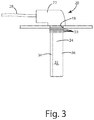
- the liquid level sensor 20 generally includes a head portion 22, visible outside of the battery cell, and a probe 24, extending into an opening 18 in the battery cell.
- the head portion 22 includes LEDs to indicate the electrolyte liquid level.
- the probe 24 houses a capacitive sensor that provides an output that varies as the liquid level within the battery cell increases or decreases in relation to the probe 24.
- the liquid level sensor 20 is in electrical communication with a communications module 26, which may also include LEDs to indicate the electrolyte liquid level.
- the output of the liquid level sensor 20 is provided to the communications module 26, which in turn outputs the detected liquid level for improved control of battery refilling operations, optionally over a ZigBee network or other wireless network, for example Bluetooth Low Energy (LE) or Wi-Fi.
- LE Bluetooth Low Energy
- the liquid level sensor 20 is further illustrated in Figs. 2-4 .
- the liquid level sensor 20 includes a head portion 22 that is visible from the exterior of the battery cell.
- the head portion 22 extends at a right angle relative to the probe 24 and includes a data/power cable 28 that extends from the head portion 22 to the communications module 26.
- the probe 24 extends downwardly from the head portion 22 and includes flexible sealing gaskets 30 to ensure a secure fit within the opening 18 in the battery 100.
- the sealing gaskets 30 are integrally formed with the probe 24 can include an outer diameter greater than the diameter of the opening 18 to prevent the escape of acid from the battery 100. As shown in Fig.
- the probe 24 is substantially vertically oriented when seated through the opening 18 in the battery 100, such that the battery liquid level can increase or decrease in relation to the liquid level sensor probe 24.
- the probe 24 includes a central member 32 and side members 34, 36 that strengthen the probe 24 and protect the central member 32 from damage.
- the central member 32 and the side members 34, 36 are coextensive in length and include an I-shaped cross-section, such that the width of the central member 32 is orthogonal to the width of the side members 34, 36.
- the central member 32 houses a capacitive liquid level sensor 40 (e.g., within a hermetic seal) for measuring the liquid level within the battery in real time.
- the liquid level sensor 20 includes an internal controller 42 and multiple electrodes 44.
- the controller 42 is a microcontroller in the present embodiment, but can include an application specific integrated circuit (ASIC) or a field programmable gate array (FPGA) in other embodiments, for example.
- the electrodes 44 include one or more primary electrode(s) 46 (pad-1 through pad-10) and one or more secondary electrode(s) 48 (a reference electrode). The one or more primary electrode(s) 46 are capacitively coupled to the one or more secondary electrode(s) 48 to define a capacitance therebetween.
- a liquid for example a electrolyte solution
- the microcontroller 42 which correlates the change to a liquid level.
- the user is then alerted to low liquid levels, optionally via LEDs in one embodiment or via an application program on a smartphone or tablet in other embodiments.
- the liquid level can be used to control the flow of liquid to a battery cell.
- a flow device can slow or stop the flow of liquid to a battery cell based on the detected liquid level.
- the flow device can control a pump in some embodiments, and can control a valve in other embodiments.
- the flow device can include an electric valve mounted to each battery cell. The electric valve can close in response to the electrolyte reaching a desired level.
- the electrodes 44 will not include a reference electrode 48.
- the electrodes 44 include only the primary electrodes 46, for example an array of electrodes serially arranged in the lengthwise direction of the probe.
- the primary electrodes 46 include a self-capacitance that is measured by the controller 42.
- the controller 42 correlates the self-capacitance of each electrode to the presence or absence of electrolyte, thereby determining the electrolyte liquid level.
- the one or more primary electrode(s) 46 includes an electrode array and the one or more secondary electrode(s) 48 includes a reference electrode.
- the reference electrode 48 is tied to a reference voltage, for example ground.
- Each electrode with the electrode array 46 is electrically coupled to the microcontroller 42.
- Each electrode within the electrode array 46 is capacitively coupled to the reference electrode 48, defining a mutual capacitance therebetween.
- the presence of a liquid, for example an electrolyte solution, in proximity to an electrode pair causes a change to the mutual capacitance.
- the change in the mutual capacitance is detected by the microcontroller 42 as a voltage increase relative to when the liquid is not present.
- the microcontroller 42 sequentially strobes each electrode within the electrode array 46 and measures its capacitive coupling to the reference electrode 48. Because the electrolyte solution is electrically capacitive, the presence of the electrolyte solution will cause a change in the capacitive coupling between the electrode array 46 and the reference electrode 48.
- the portion of the electrode array 46 having a nominal capacitance is determined by the microcontroller 42 to be above the liquid level, and the portion of the electrode array 46 having an increased capacitance is determined by the microcontroller 42 to be below the liquid level. For example, if pad-1 through pad-5 have a nominal capacitance, while pad-6 through pad-10 have a heightened capacitance, the microcontroller 42 can determine the liquid level to be between pad-5 and pad-6.
- the microcontroller 42 can determine the liquid level to be between pad-7 and pad-8. Still further by example, if pad-1 through pad-10 have a nominal capacitance, the microcontroller 42 can determine the liquid level to be below pad-10.
- the microcontroller 42 can determine the approximate liquid level according to any desired technique. In some embodiments the microcontroller 42 determines the liquid level by comparing each measured capacitance against a threshold capacitance stored to computer readable memory. In other embodiments, the microcontroller 42 determines the liquid level by comparing each measured capacitance against the capacitance at the uppermost electrode, e.g., pad-1. In still other embodiments, the microcontroller 42 determines the liquid level by comparing a change in capacitance over time (e.g., the change in capacitance over successive readings of the same electrode) to a threshold change that is stored to computer readable memory, such that a spike in capacitance corresponds to the presence of a electrolyte solution.
- a change in capacitance over time e.g., the change in capacitance over successive readings of the same electrode
- the liquid level sensor 20 additionally includes programming interface 50, a serial debugger interface 52, an on-board thermistor 54, on-board indicators 56, and a four-pin wire-to-wire connector 58.
- the programming interface 50 receives computer readable instructions for carrying out the liquid level measurement described above.
- the serial debugger interface 52 supports data transfer to verify the liquid level sensor 20 is working properly before packaging and shipment.
- the on-board thermistor 54 provides a temperature measurement for output to the microcontroller 42. As shown in Fig. 7 , the thermistor is 54 is positioned at the lower-most extent of the probe 24 opposite of the reference electrode 48.
- the microcontroller 42 can determine the electrolyte temperature (if the thermistor is below the detected liquid level) or the air temperature (if the thermistor electrode is above the detected liquid level) within the battery 100.
- the on-board indicators 56 provide immediate feedback regarding the detected liquid level.
- the on-board indicators 56 include three LEDs: a steady green LED, a steady red LED, and a flashing red LED.
- the steady green LED can indicate the liquid level is within an acceptable range.
- the flashing red LED can indicate the liquid level is below an acceptable range.
- the steady red LED can indicate the liquid level is above an acceptable range.
- the on-board indicators 56 can also or alternatively be present elsewhere, for example the communications module 26, a handheld unit, or a desktop unit.
- the wire-to-wire connector 58 includes four pins in the present embodiment, two to the microcontroller (5V and ground) and two to the serial debugger interface 52 (transfer and receive).
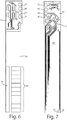
- Fig. 6 depicts a printed circuit board including the electrode array 46 and the reference electrode 48.
- the electrode array 46 includes multiple array electrodes that are serially disclosed in a lengthwise direction of the probe 24.
- the array electrodes 46 are formed from copper in the present embodiment and are spaced apart at 0.1" increments.
- an "array" includes two or more elements arranged in an ordered relationship, e.g., a row or a column. Though eleven array electrodes or “capacitive pads" are shown in the present embodiment, greater or fewer array electrodes can be included in other embodiments.
- Each array electrode is electrically isolated from the remaining array electrodes and from the reference electrode 48.
- the electrode array 46 is laterally offset from the reference electrode 48 and is coextensive in length with the reference electrode 48.
- the electrode array 46 and the reference electrode 48 extend along a common lengthwise surface of the probe 24, being mounted to a common dielectric substrate 60.
- the reference electrode 48 is elongated, having a length substantially greater than its width, and is coupled to the ground plane 62.
- the four-pin connector 58 is also shown in Fig. 6 including a ground pin 64, a 5V pin 66, and two serial connections 68 and 70.
- the reverse side of the circuit board is depicted in Fig. 7 .
- the microcontroller 42 is visible, the microcontroller 42 being electrically connected to each array electrode within the electrode array 46.
- the thermistor 54 is also visible, being disposed on the lowermost extent of the circuit board.
- the four-pin connector 58 is also shown in Fig. 7 including a ground pin 64, a 5V pin 66, and two serial pins 68 and 70.
- the circuit board 60 is typically overmolded or potted within the probe 24 of Figs. 2-4 to protect the electrodes 44 from corrosion.
- a flow diagram illustrates operation of a stand-alone liquid level sensor 20.
- the steady green LED is illuminated at step 74.
- the microcontroller 42 initiates a new sample by reading the capacitance at each array electrode 46 and storing the measured values to computer readable memory.
- the microcontroller 42 either resamples or continues to step 80.
- the microcontroller 42 averages the measured values for each array electrode 46 and stores the average to computer readable memory.
- the microcontroller 42 compares the average for each array electrode with a predetermined range that is stored to computer readable memory.
- the microcontroller If the average for any one of the array electrodes is above the predetermined range, the microcontroller illuminates the steady red LED and turns off all other LEDs at step 84. If the average for all of the array electrodes is within the predetermined range, the microcontroller illuminates the steady green LED and turns off all other LEDs at step 86. If the average for any one of the array electrodes is below the predetermined range, the microcontroller illuminates the flashing red LED and turns off all other LEDs at step 88. At step 90, the microcontroller 42 initiates a new sample when appropriate and based on the configurable sample rate.
- a flow diagram illustrates operation of the liquid level sensor system.
- the microcontroller 42 waits until a system controller ("system micro") requests data via the serial connection 52 at step 104.
- the sample rate can be determined by the microcontroller 42, optionally once every 10 seconds.
- the microcontroller 42 determines if data has been requested by the system micro. If data has not been requested, the microcontroller 42 waits for another sample period (e.g., 10 seconds). If data has been requested, the microcontroller 42 determines if the data is the liquid level data or the temperature data at decision step 108.
- the microcontroller 42 samples all array electrodes 46 (or capacitive pads) and stores the data to memory at step 110. If temperature data is requested, the microcontroller 42 samples the voltage reading from the thermistor 54 at step 112, optionally via a voltage divider. At step 114, the microcontroller 42 sends the measured data to the system micro via the serial connection 52, optionally using the communications module 26.
- the size of the data packet can depend on the original data request, e.g., liquid level or temperature or both liquid level and temperature.
- the system micro can be hosted on a remote device, for example a smartphone, a tablet, a laptop, or a desktop computer.
- the embodiments discussed above provide a liquid level sensor for a battery monitoring system and a corresponding method of operation.
- the liquid level sensor remains permanently affixed to the battery 100 in the present embodiment, but can be removed between refilling operations in other embodiments.
- the method of operation generally includes measuring the capacitance between the reference electrode 48 and each array electrode, i.e., each electrode within the electrode array 46, and determining the liquid level within the battery 100 based on the capacitance measurements.
- the method can additionally include communicating the detected liquid level to a remote device, for example a handheld unit or a desktop unit, via the communications module 26. Communication of the detected liquid level is set forth in US Application No.
- the communications module 26 can communicate with the remote device over a ZigBee network or other wireless network, for example Bluetooth, Bluetooth Smart (BLE), or Wi-Fi.
- the communications module 26 can additionally communicate temperature data to the remote device in accordance with the flow diagram of Fig. 9 .
- the method of the present embodiments can additionally include controlling the flow of water to the battery cell in response to the liquid level measurements.
- a flow device optionally a pump or a valve, can slow or stop the flow of water to the battery 100 based on the determined liquid level within the battery 100.
- the flow device can initiate or increase the flow of water to the battery 100 based on the determined liquid level within the battery 100.
- the liquid level readings and the temperature readings can also be communicated wirelessly by the communications module 26 to an application program hosted on a smartphone, a tablet, a laptop, or a desktop computer.
- the liquid level sensor 20 can provide real-time information during battery refilling operations, while also ensuring the appropriate liquid level within each battery cell is maintained between battery refilling operations.
Landscapes
- Physics & Mathematics (AREA)
- Engineering & Computer Science (AREA)
- Power Engineering (AREA)
- Thermal Sciences (AREA)
- Electromagnetism (AREA)
- Fluid Mechanics (AREA)
- General Physics & Mathematics (AREA)
- Electrochemistry (AREA)
- General Chemical & Material Sciences (AREA)
- Chemical Kinetics & Catalysis (AREA)
- Chemical & Material Sciences (AREA)
- Manufacturing & Machinery (AREA)
- Measurement Of Levels Of Liquids Or Fluent Solid Materials (AREA)
Description
- The present invention relates to a liquid level sensor, and more particularly, a liquid level sensor for liquid electrolyte battery monitoring systems.
- Reference may be made to any of:
-
US 2011/128154 A1 , which relates to a battery electrolyte monitor including a probe and a control circuit, wherein the control circuit includes a capacitive element within the probe, the probe is acid resistant and therefore the probe protects the capacitive element from contact with the battery electrolyte, the control circuit periodically charges and discharges the capacitive element using direct current, and depending on at least one of a charging characteristic and a discharging characteristic, the control circuit determines the electrolyte level, wherein if the electrolyte is below a desired minimum level, the control circuit illuminates an indicator light; -
US 5 613 399 A , which relates to a digital liquid level sensing apparatus and method for detecting variations in the dielectric of a substance being sensed, wherein the apparatus includes a capacitive element array which is disposed in a fluid to be measured and which includes a plurality of individual (i.e., segmented) input plates positioned along an axis of measurement of the fluid to be detected, wherein the array also includes a common output plate having a length sufficient to span the entire accumulated length of the input plates, wherein a controller sequentially applies DC excitation pulses to the input plates which cause a series of output currents to be coupled onto the output plate, wherein the output currents are input to a current-to-voltage amplifier which generates a series of corresponding analog output voltages, wherein the analog output voltages are then input to a peak voltage detector circuit to generate a series of peak voltage signals representative of the magnitudes of the analog output voltages, wherein the controller converts each of the peak voltage signals into a corresponding digital value and stores each of the digital values in an on-board memory, wherein the controller then sequentially compares each of the values against at least one predetermined reference value indicative of an output produced by an input plate disposed in air until a predetermined difference is detected between the reference value and any one of the stored digital values, which indicates a predetermined difference in the dielectric, thus indicating that a corresponding input plate is at least partially submerged in fluid; and -
US 2012/058369 A1 , which relates to a system for delivering water to a fluid electrolyte battery comprising at least one battery cell, wherein such a system includes a tank adapted to hold the fluid, a pump adapted to pump the fluid from the tank when the pump is turned on, at least one conduit adapted to transfer the fluid from the tank to the at least one battery cell, and a controller adapted to control the pump, wherein the controller turns the pump on after an interval so that the fluid is transferred to the at least one battery cell. - Liquid electrolyte batteries, including lead-acid batteries, provide electrical energy by means of an electrochemical reaction. The electrochemical reaction involves the reaction of an acid, for example sulfuric acid, with a battery electrode. Recharging of liquid electrolyte batteries is also made possible by an electrochemical reaction, in which water is converted into hydrogen and oxygen. As a result of the recharging reaction and from heat induced water evaporation, however, liquid electrolyte batteries experience a loss of water, and must be refilled with water on a regular basis.
- Accordingly, a variety of watering systems have been developed for refilling liquid electrolyte batteries. One such system includes a single point watering system, in which a single source of water is directed to multiple battery cells within the liquid electrolyte battery. Conventional single point watering system include shut-off valves that permanently replace existing venting caps for each battery cell within the liquid electrolyte battery. The shut-off valves automatically terminate the flow of water to the battery cells when the battery cells are substantially full.
- Despite the widespread acceptance of existing single point watering systems, watering systems today do not alert users as to when to add water to a battery. Therefore, many different electrolyte level indicators exist in the marketplace. Commonplace electrolyte indicators use a conductive material protruding into a battery cell. The commonplace electrolyte level indicators determine whether or not the probe is contacting electrolyte. The commonplace electrolyte level indicators cannot determine the amount of electrolyte in a cell beyond the point of contact. Therefore, there remains a continued need for improved battery electrolyte level indicators that accurately measure the water level within liquid electrolyte batteries for forklifts, reach trucks, standby power and other applications.
- The present invention is defined by the independent claims to which reference should be made. Specific embodiments are defined in the dependent claims. A liquid level sensor for a battery monitoring system is provided. The liquid level sensor includes a probe having a capacitive sensor. The capacitive sensor provides an output that varies as the liquid level increases in relation to the probe. The liquid level sensor can be used to alert a user of the need to refill the battery or to alert a user of the need to refill the battery in the near future. The liquid level sensor can include a series of LEDs that selectively illuminate to indicate each such condition to the user, for example.
- In one arrangement, the capacitive sensor includes an electrode array and a reference electrode. The electrode array includes a plurality of electrodes that are serially disposed in a lengthwise direction of the probe. The reference electrode is capacitively coupled to each electrode within the electrode array, such that the capacitive coupling can vary as the liquid level increases in relation to the probe. The electrode array and the reference electrode are mounted to a common dielectric substrate, for example a printed circuit board. The printed circuit board is overmolded or potted to protect the electrodes against the electrolyte solution within the battery cell.
- In another arrangement, the capacitive sensor includes a controller adapted to measure the capacitive coupling between the reference electrode and the electrode array. The output of controller can be used to control the flow of liquid to a battery cell or a plurality of battery cells. For example, a flow device can slow or stop the flow of liquid to a battery cell based on the detected liquid level. The flow device can include a pump in some arrangements, and can include a valve in other arrangements. Further by example, the flow device can include an electric valve mounted to each cell in the battery. The electric valve can close in response to the electrolyte reaching a desired level. The probe can additionally include a thermistor that is electrically coupled to the controller for measuring the temperature of the electrolyte solution within the battery cell.
- In another arrangement, a method for measuring a liquid level in a battery is provided. The method includes providing a probe including a reference electrode and an electrode array having a plurality of electrodes that are capacitively coupled to the reference electrode. The method further includes measuring each capacitive coupling, determining the liquid level within a battery cell based on each capacitive coupling. The determined liquid level is shared with a remote server for storage and analysis, and optionally used to control the flow of liquid into the battery cell. Measuring each capacitive coupling can include measuring the capacitance between the reference electrode and each electrode within the electrode array. Determining the liquid level can include detecting a change in capacitance along the lengthwise direction of probe, optionally corresponding to the liquid level within the battery cell.
- The present invention can therefore provide an improved liquid level sensor for a liquid electrolyte battery, for example a lead-acid battery. The liquid level sensor can provide real-time liquid level information and temperature information during battery refilling operations, while also monitoring the liquid level within a battery cell or a plurality of battery cells between refills. The liquid level readings and the temperature readings can be communicated wirelessly to an application program hosted on a remote device, for example a smartphone, a tablet, a laptop, or a desktop computer.
- These and other features and advantages of the present invention will become apparent from the following description of the invention, when viewed in accordance with the accompanying drawings and appended claims.
-
-
Fig. 1 is a perspective view of a single point watering system including a liquid level sensor in accordance with one embodiment of the invention. -
Fig. 2 is a perspective view of a liquid level sensor probe above a battery cell opening for a liquid electrolyte battery. -
Fig. 3 is a cross-sectional view of the liquid level sensor probe taken along line 3-3 ofFig. 1 . -
Fig. 4 is a perspective view of the liquid level sensor probe in accordance with an embodiment of the present invention. -
Fig. 5 is a schematic diagram of the liquid level sensor in accordance with an embodiment of the present invention. -
Fig. 6 is a top layer of a capacitive sensor including an electrode array and a reference electrode. -
Fig. 7 is a bottom layer of a capacitive sensor including a microcontroller electrically connected to an electrode array and a reference electrode. -
Fig. 8 is a flow diagram illustrating calibration of the liquid level sensor in accordance with an embodiment of the present invention. -
Fig. 9 is a flow diagram illustrating operation of the liquid level sensor in accordance with an embodiment of the present invention. - The invention as contemplated and disclosed herein includes a liquid level sensor for a battery monitoring system. As set forth below, the liquid level sensor includes a probe having a capacitive sensor. The capacitive sensor provides an output that varies as the liquid level increases in relation to the probe, thereby sensing a plurality of non-zero liquid levels. The liquid level sensor can be used in monitoring and alerting users to the electrolyte level, thereby improving battery operation and longevity for liquid electrolyte batteries, including lead-acid batteries.
- Referring now to
Fig. 1 , a single point watering system is illustrated and generally designated 10. The singlepoint watering system 10 includes arefill control valve 12 for each battery cell of a lead-acid battery 100. Therefill control valves 12 are joined by a section offlexible tubing 14. Theflexible tubing 14 provides a fluid flow path for water from aninlet 16 to each of therefill control valves 12. The lead-acid battery 100 also includes aliquid level sensor 20 for at least one of the battery cells. Theliquid level sensor 20 generally includes ahead portion 22, visible outside of the battery cell, and aprobe 24, extending into anopening 18 in the battery cell. In one embodiment, thehead portion 22 includes LEDs to indicate the electrolyte liquid level. As discussed in greater detail below, theprobe 24 houses a capacitive sensor that provides an output that varies as the liquid level within the battery cell increases or decreases in relation to theprobe 24. As also discussed below, theliquid level sensor 20 is in electrical communication with acommunications module 26, which may also include LEDs to indicate the electrolyte liquid level. The output of theliquid level sensor 20 is provided to thecommunications module 26, which in turn outputs the detected liquid level for improved control of battery refilling operations, optionally over a ZigBee network or other wireless network, for example Bluetooth Low Energy (LE) or Wi-Fi. - The
liquid level sensor 20 is further illustrated inFigs. 2-4 . As noted above, theliquid level sensor 20 includes ahead portion 22 that is visible from the exterior of the battery cell. Thehead portion 22 extends at a right angle relative to theprobe 24 and includes a data/power cable 28 that extends from thehead portion 22 to thecommunications module 26. Theprobe 24 extends downwardly from thehead portion 22 and includesflexible sealing gaskets 30 to ensure a secure fit within theopening 18 in thebattery 100. The sealinggaskets 30 are integrally formed with theprobe 24 can include an outer diameter greater than the diameter of theopening 18 to prevent the escape of acid from thebattery 100. As shown inFig. 3 , theprobe 24 is substantially vertically oriented when seated through theopening 18 in thebattery 100, such that the battery liquid level can increase or decrease in relation to the liquidlevel sensor probe 24. Theprobe 24 includes acentral member 32 andside members probe 24 and protect thecentral member 32 from damage. Thecentral member 32 and theside members central member 32 is orthogonal to the width of theside members central member 32 houses a capacitive liquid level sensor 40 (e.g., within a hermetic seal) for measuring the liquid level within the battery in real time. - Referring now to
Fig. 5 , a schematic diagram for theliquid level sensor 20 is illustrated. Theliquid level sensor 20 includes aninternal controller 42 andmultiple electrodes 44. Thecontroller 42 is a microcontroller in the present embodiment, but can include an application specific integrated circuit (ASIC) or a field programmable gate array (FPGA) in other embodiments, for example. Theelectrodes 44 include one or more primary electrode(s) 46 (pad-1 through pad-10) and one or more secondary electrode(s) 48 (a reference electrode). The one or more primary electrode(s) 46 are capacitively coupled to the one or more secondary electrode(s) 48 to define a capacitance therebetween. The presence of a liquid, for example a electrolyte solution, in proximity to theelectrodes 44 changes the capacitive coupling between the one or more primary electrode(s) 46 and the one or more secondary electrode(s) 48. This change in capacitance is detected by themicrocontroller 42, which correlates the change to a liquid level. The user is then alerted to low liquid levels, optionally via LEDs in one embodiment or via an application program on a smartphone or tablet in other embodiments. In still other embodiments, the liquid level can be used to control the flow of liquid to a battery cell. For example, a flow device can slow or stop the flow of liquid to a battery cell based on the detected liquid level. The flow device can control a pump in some embodiments, and can control a valve in other embodiments. Further by example, the flow device can include an electric valve mounted to each battery cell. The electric valve can close in response to the electrolyte reaching a desired level. - Though the embodiment described above includes a
reference electrode 48, in other embodiments theelectrodes 44 will not include areference electrode 48. In these embodiments, theelectrodes 44 include only theprimary electrodes 46, for example an array of electrodes serially arranged in the lengthwise direction of the probe. Theprimary electrodes 46 include a self-capacitance that is measured by thecontroller 42. Thecontroller 42 correlates the self-capacitance of each electrode to the presence or absence of electrolyte, thereby determining the electrolyte liquid level. - Returning to the embodiment illustrated in
Fig. 6 , the one or more primary electrode(s) 46 includes an electrode array and the one or more secondary electrode(s) 48 includes a reference electrode. Thereference electrode 48 is tied to a reference voltage, for example ground. Each electrode with theelectrode array 46 is electrically coupled to themicrocontroller 42. Each electrode within theelectrode array 46 is capacitively coupled to thereference electrode 48, defining a mutual capacitance therebetween. The presence of a liquid, for example an electrolyte solution, in proximity to an electrode pair causes a change to the mutual capacitance. The change in the mutual capacitance is detected by themicrocontroller 42 as a voltage increase relative to when the liquid is not present. - In one embodiment, the
microcontroller 42 sequentially strobes each electrode within theelectrode array 46 and measures its capacitive coupling to thereference electrode 48. Because the electrolyte solution is electrically capacitive, the presence of the electrolyte solution will cause a change in the capacitive coupling between theelectrode array 46 and thereference electrode 48. The portion of theelectrode array 46 having a nominal capacitance is determined by themicrocontroller 42 to be above the liquid level, and the portion of theelectrode array 46 having an increased capacitance is determined by themicrocontroller 42 to be below the liquid level. For example, if pad-1 through pad-5 have a nominal capacitance, while pad-6 through pad-10 have a heightened capacitance, themicrocontroller 42 can determine the liquid level to be between pad-5 and pad-6. Similarly, if pad-1 through pad-7 have a nominal capacitance, while pad-8 through pad-10 have a heightened capacitance, themicrocontroller 42 can determine the liquid level to be between pad-7 and pad-8. Still further by example, if pad-1 through pad-10 have a nominal capacitance, themicrocontroller 42 can determine the liquid level to be below pad-10. - The
microcontroller 42 can determine the approximate liquid level according to any desired technique. In some embodiments themicrocontroller 42 determines the liquid level by comparing each measured capacitance against a threshold capacitance stored to computer readable memory. In other embodiments, themicrocontroller 42 determines the liquid level by comparing each measured capacitance against the capacitance at the uppermost electrode, e.g., pad-1. In still other embodiments, themicrocontroller 42 determines the liquid level by comparing a change in capacitance over time (e.g., the change in capacitance over successive readings of the same electrode) to a threshold change that is stored to computer readable memory, such that a spike in capacitance corresponds to the presence of a electrolyte solution. - Referring again to
Fig. 5 , theliquid level sensor 20 additionally includesprogramming interface 50, aserial debugger interface 52, an on-board thermistor 54, on-board indicators 56, and a four-pin wire-to-wire connector 58. Theprogramming interface 50 receives computer readable instructions for carrying out the liquid level measurement described above. Theserial debugger interface 52 supports data transfer to verify theliquid level sensor 20 is working properly before packaging and shipment. The on-board thermistor 54 provides a temperature measurement for output to themicrocontroller 42. As shown inFig. 7 , the thermistor is 54 is positioned at the lower-most extent of theprobe 24 opposite of thereference electrode 48. By measuring the resistance of the thermistor, optionally using a voltage divider, themicrocontroller 42 can determine the electrolyte temperature (if the thermistor is below the detected liquid level) or the air temperature (if the thermistor electrode is above the detected liquid level) within thebattery 100. The on-board indicators 56 provide immediate feedback regarding the detected liquid level. In some embodiments, the on-board indicators 56 include three LEDs: a steady green LED, a steady red LED, and a flashing red LED. The steady green LED can indicate the liquid level is within an acceptable range. The flashing red LED can indicate the liquid level is below an acceptable range. The steady red LED can indicate the liquid level is above an acceptable range. Though described as being present on theliquid level sensor 20, the on-board indicators 56 can also or alternatively be present elsewhere, for example thecommunications module 26, a handheld unit, or a desktop unit. Lastly, the wire-to-wire connector 58 includes four pins in the present embodiment, two to the microcontroller (5V and ground) and two to the serial debugger interface 52 (transfer and receive). - Referring now to
Figs. 6-7 , the circuit board for theliquid level sensor 20 in accordance with one embodiment is illustrated. More particularly,Fig. 6 depicts a printed circuit board including theelectrode array 46 and thereference electrode 48. Theelectrode array 46 includes multiple array electrodes that are serially disclosed in a lengthwise direction of theprobe 24. Thearray electrodes 46 are formed from copper in the present embodiment and are spaced apart at 0.1" increments. As the term is used herein, an "array" includes two or more elements arranged in an ordered relationship, e.g., a row or a column. Though eleven array electrodes or "capacitive pads" are shown in the present embodiment, greater or fewer array electrodes can be included in other embodiments. Each array electrode is electrically isolated from the remaining array electrodes and from thereference electrode 48. Theelectrode array 46 is laterally offset from thereference electrode 48 and is coextensive in length with thereference electrode 48. Theelectrode array 46 and thereference electrode 48 extend along a common lengthwise surface of theprobe 24, being mounted to acommon dielectric substrate 60. Thereference electrode 48 is elongated, having a length substantially greater than its width, and is coupled to theground plane 62. The four-pin connector 58 is also shown inFig. 6 including aground pin 64, a5V pin 66, and twoserial connections Fig. 7 . In particular, themicrocontroller 42 is visible, themicrocontroller 42 being electrically connected to each array electrode within theelectrode array 46. Thethermistor 54 is also visible, being disposed on the lowermost extent of the circuit board. The four-pin connector 58 is also shown inFig. 7 including aground pin 64, a5V pin 66, and twoserial pins circuit board 60 is typically overmolded or potted within theprobe 24 ofFigs. 2-4 to protect theelectrodes 44 from corrosion. - Referring now to
Fig. 8 , a flow diagram illustrates operation of a stand-aloneliquid level sensor 20. Upon commencement of an operation algorithm atstep 72, the steady green LED is illuminated atstep 74. Atstep 76, themicrocontroller 42 initiates a new sample by reading the capacitance at eacharray electrode 46 and storing the measured values to computer readable memory. Atdecision step 78, themicrocontroller 42 either resamples or continues to step 80. Atstep 80, themicrocontroller 42 averages the measured values for eacharray electrode 46 and stores the average to computer readable memory. Atdecision step 82, themicrocontroller 42 compares the average for each array electrode with a predetermined range that is stored to computer readable memory. If the average for any one of the array electrodes is above the predetermined range, the microcontroller illuminates the steady red LED and turns off all other LEDs atstep 84. If the average for all of the array electrodes is within the predetermined range, the microcontroller illuminates the steady green LED and turns off all other LEDs atstep 86. If the average for any one of the array electrodes is below the predetermined range, the microcontroller illuminates the flashing red LED and turns off all other LEDs atstep 88. Atstep 90, themicrocontroller 42 initiates a new sample when appropriate and based on the configurable sample rate. - Referring now to
Fig. 9 , a flow diagram illustrates operation of the liquid level sensor system. After commencement of a measurement algorithm atstep 102, themicrocontroller 42 waits until a system controller ("system micro") requests data via theserial connection 52 atstep 104. The sample rate can be determined by themicrocontroller 42, optionally once every 10 seconds. Atdecision step 106, themicrocontroller 42 determines if data has been requested by the system micro. If data has not been requested, themicrocontroller 42 waits for another sample period (e.g., 10 seconds). If data has been requested, themicrocontroller 42 determines if the data is the liquid level data or the temperature data atdecision step 108. If liquid level data is requested, themicrocontroller 42 samples all array electrodes 46 (or capacitive pads) and stores the data to memory atstep 110. If temperature data is requested, themicrocontroller 42 samples the voltage reading from thethermistor 54 atstep 112, optionally via a voltage divider. Atstep 114, themicrocontroller 42 sends the measured data to the system micro via theserial connection 52, optionally using thecommunications module 26. The size of the data packet can depend on the original data request, e.g., liquid level or temperature or both liquid level and temperature. The system micro can be hosted on a remote device, for example a smartphone, a tablet, a laptop, or a desktop computer. - To reiterate, the embodiments discussed above provide a liquid level sensor for a battery monitoring system and a corresponding method of operation. The liquid level sensor remains permanently affixed to the
battery 100 in the present embodiment, but can be removed between refilling operations in other embodiments. The method of operation generally includes measuring the capacitance between thereference electrode 48 and each array electrode, i.e., each electrode within theelectrode array 46, and determining the liquid level within thebattery 100 based on the capacitance measurements. The method can additionally include communicating the detected liquid level to a remote device, for example a handheld unit or a desktop unit, via thecommunications module 26. Communication of the detected liquid level is set forth inUS Application No. 15/079,124 communications module 26 can communicate with the remote device over a ZigBee network or other wireless network, for example Bluetooth, Bluetooth Smart (BLE), or Wi-Fi. Thecommunications module 26 can additionally communicate temperature data to the remote device in accordance with the flow diagram ofFig. 9 . During refilling operations, the method of the present embodiments can additionally include controlling the flow of water to the battery cell in response to the liquid level measurements. For example, a flow device, optionally a pump or a valve, can slow or stop the flow of water to thebattery 100 based on the determined liquid level within thebattery 100. Further by example the flow device can initiate or increase the flow of water to thebattery 100 based on the determined liquid level within thebattery 100. The liquid level readings and the temperature readings can also be communicated wirelessly by thecommunications module 26 to an application program hosted on a smartphone, a tablet, a laptop, or a desktop computer. Theliquid level sensor 20 can provide real-time information during battery refilling operations, while also ensuring the appropriate liquid level within each battery cell is maintained between battery refilling operations. - The above description is that of current embodiments of the invention. Various alterations and changes can be made without departing from broader aspects of the invention as defined in the appended claims, which are to be interpreted in accordance with the principles of patent law. Any reference to elements in the singular, for example, using the articles "a," "an," "the," or "said," is not to be construed as limiting the element to the singular.
Claims (15)
- A battery electrolyte level monitoring system for a battery (100) having a plurality of cells containing liquid electrolyte, the system comprising:a probe (24) for insertion into one cell of the plurality of cells of the liquid electrolyte battery (100), being characterised in that the probe (24) includes:a reference electrode (48), andan electrode array (46) including a plurality of array electrodes arranged in a lengthwise direction of the probe (24), wherein the reference electrode (48) is capacitively coupled to each array electrode; anda controller (42) electrically coupled to the electrode array (46), the controller (42) being adapted to:for each array electrode, determine a measured value of a capacitive coupling between the reference electrode (48) and the array electrode,store the measured value for each array electrode,determine an average value of measured values for each array electrode over time,store the average value for each array electrode,compare the average value for each array electrode with a predetermined range corresponding to an acceptable range of the level of the liquid electrolyte within the one cell of the liquid electrolyte battery (100), andprovide a first output if any one of the average values for the array electrodes is above the predetermined range, a second output if all of the average values for the array electrodes are within the predetermined range, and a third output if any one of the average values for the array electrodes is below the predetermined range, the first, second, and third outputs being different from one another.
- The system of claim 1 wherein the electrode array (46) is laterally offset from the reference electrode (48) and coextensive in length with the reference electrode (48).
- The system of claim 1 wherein the probe (24) further includes a temperature sensor (54) on an end portion of the probe (24).
- The system of claim 1 further including first, second, and third on-board indicators (56) providing the first, second, and third outputs respectively.
- The system of claim 1 wherein the controller (42) includes a communications module (26) operable to transmit the first, second, and third outputs.
- The system of claim 1 further including a battery watering system responsive to the controller (42) and operable to control the flow of water into the liquid electrolyte battery (100).
- The sensing system of claim 6 wherein the battery watering system includes a pump or a valve.
- The system of claim 1 wherein the controller (42) comprises a microcontroller, an application specific integrated circuit, or a field programmable gate array.
- A battery electrolyte level monitoring method for measuring a liquid level within a cell of a liquid electrolyte battery, the method comprising:providing a probe including a reference electrode and an electrode array having a plurality of array electrodes arranged in a lengthwise direction of the probe;for each array electrode, determining a measured value of a capacitive coupling between the reference electrode and the array electrode;storing the measured value for each array electrode;determining an average value for each array electrode over time;storing the average value for each array electrode;comparing the average value for each array electrode with a predetermined range corresponding to an acceptable range of the level of the liquid electrolyte within the cell of the battery; andproviding a first output in response to any one of the average values for the array electrodes being above the predetermined range, a second output in response to all of the average values for the array electrodes being within the predetermined range, and a third output in response to any one of the average values for the array electrodes being below the predetermined range, the first, second, and third outputs being different from one another.
- The method according to claim 9 further including communicating the first, second, and third outputs to a remote device.
- The method according to claim 10 wherein said step of communicating is performed over a wireless network.
- The method according to claim 9 further including controlling the flow of a liquid into the battery cell based on the first, second, and third outputs.
- The method according to claim 12 wherein controlling the flow of a liquid into the battery cell includes controlling a pump or controlling a valve.
- The method according to claim 9 wherein the electrode array is adjacent the reference electrode.
- The method according to claim 9 wherein the reference electrode and the electrode array extend along a common lengthwise surface of the probe.
Applications Claiming Priority (2)
| Application Number | Priority Date | Filing Date | Title |
|---|---|---|---|
| US15/079,125 US10381693B2 (en) | 2016-03-24 | 2016-03-24 | Liquid level sensor for battery monitoring systems |
| PCT/US2016/068880 WO2017164957A1 (en) | 2016-03-24 | 2016-12-28 | Liquid level sensor for battery monitoring systems |
Publications (3)
| Publication Number | Publication Date |
|---|---|
| EP3440733A1 EP3440733A1 (en) | 2019-02-13 |
| EP3440733A4 EP3440733A4 (en) | 2019-11-27 |
| EP3440733B1 true EP3440733B1 (en) | 2021-04-28 |
Family
ID=59898189
Family Applications (1)
| Application Number | Title | Priority Date | Filing Date |
|---|---|---|---|
| EP16895728.0A Active EP3440733B1 (en) | 2016-03-24 | 2016-12-28 | Liquid level sensor for battery monitoring systems |
Country Status (9)
| Country | Link |
|---|---|
| US (1) | US10381693B2 (en) |
| EP (1) | EP3440733B1 (en) |
| JP (1) | JP6619892B2 (en) |
| CN (1) | CN108886178B (en) |
| AU (1) | AU2016398499B2 (en) |
| CA (1) | CA3014447C (en) |
| NZ (1) | NZ745601A (en) |
| WO (1) | WO2017164957A1 (en) |
| ZA (1) | ZA201805382B (en) |
Families Citing this family (10)
| Publication number | Priority date | Publication date | Assignee | Title |
|---|---|---|---|---|
| US10326171B2 (en) | 2016-03-24 | 2019-06-18 | Flow-Rite Controls, Ltd. | Intelligent monitoring systems for liquid electrolyte batteries |
| US10408660B2 (en) * | 2016-08-11 | 2019-09-10 | Orscheln Products L.L.C. | Electronic fluid level indicator |
| CN108709489B (en) * | 2018-05-12 | 2023-07-25 | 中国科学院南京地理与湖泊研究所 | A biosensor and monitoring method for monitoring sediment expansion height |
| CN110907056A (en) * | 2018-09-14 | 2020-03-24 | 宁德时代新能源科技股份有限公司 | A battery pack temperature detection system |
| CN111829613A (en) * | 2019-04-22 | 2020-10-27 | 密克罗奇普技术公司 | Bipolar Mutual Capacitance Liquid Sensing |
| JP2022015690A (en) * | 2020-07-09 | 2022-01-21 | パナソニックIpマネジメント株式会社 | Liquid level position sensor, liquid level position detection method, and program |
| CN113155008B (en) * | 2021-03-10 | 2022-10-11 | 广东化一环境科技有限公司 | Thickness detection equipment and detection method for layered medium |
| WO2023018337A1 (en) | 2021-08-11 | 2023-02-16 | Enatel | Combined liquid electrolyte and temperature sensor |
| CN115458850A (en) * | 2022-10-10 | 2022-12-09 | 中国久远高新技术装备有限公司 | Energy storage battery with liquid leakage preventing and absorbing structure |
| CN117928684B (en) * | 2024-03-22 | 2024-06-07 | 北京晨淼科技有限公司 | Portable electric solution level tester and testing method thereof |
Family Cites Families (23)
| Publication number | Priority date | Publication date | Assignee | Title |
|---|---|---|---|---|
| US4349882A (en) * | 1980-08-22 | 1982-09-14 | Veeder Industries Inc. | Liquid level measuring system |
| US4329406A (en) * | 1981-03-27 | 1982-05-11 | Dahl Ernest A | Specific gravity transducer and battery performance indicator |
| US5417849A (en) * | 1993-02-24 | 1995-05-23 | Henry Filters, Inc. | Machine tool coolant filtering system |
| US5613399A (en) * | 1993-10-27 | 1997-03-25 | Kdi Precision Products, Inc. | Method for liquid level detection |
| US5710503A (en) | 1996-02-01 | 1998-01-20 | Aims Systems, Inc. | On-line battery monitoring system with defective cell detection capability |
| WO2001059411A1 (en) * | 2000-02-08 | 2001-08-16 | Keller John W | Method and apparatus for monitoring liquid level in a container |
| JP4208572B2 (en) | 2000-12-20 | 2009-01-14 | アバータックス・リサーチ・アンド・ディベロップメント・リミテッド | Method and apparatus for measuring levels |
| JP3849867B2 (en) * | 2002-07-24 | 2006-11-22 | ソニー株式会社 | Liquid detection device and liquid amount detection device |
| DE10261767A1 (en) * | 2002-12-19 | 2004-07-15 | Hydac Electronic Gmbh | Device and method for measuring capacitance and device for determining the level of a liquid with such a device |
| ZA200307734B (en) * | 2003-01-22 | 2004-06-10 | Flow Rite Control Ltd | Apparatus for use of single point watering system with monobloc lead-acid batteries. |
| WO2004112169A2 (en) * | 2003-06-12 | 2004-12-23 | Philadelphia Scientific | System and method for monitoring electrolyte levels in a battery |
| US6918296B1 (en) * | 2004-03-04 | 2005-07-19 | Delphi Technologies, Inc. | Method of measuring fluid phases in a reservoir |
| AU2005234650A1 (en) | 2004-11-17 | 2006-06-01 | Fitter, Johan Christiaan | Automated battery watering control system |
| EP2254177A3 (en) | 2005-05-28 | 2011-09-21 | Aerovironment inc. | Battery electrolyte level control system |
| US20100019773A1 (en) * | 2008-07-28 | 2010-01-28 | Son Hong K | Battery monitoring device |
| US20110082621A1 (en) | 2009-10-02 | 2011-04-07 | Eric Berkobin | Method and system for predicting battery life based on vehicle battery, usage, and environmental data |
| US20110128154A1 (en) * | 2009-12-01 | 2011-06-02 | Flow-Rite Controls, Ltd. | Battery electrolyte level indicator |
| CN201583315U (en) * | 2010-02-10 | 2010-09-15 | 中国电子科技集团公司第四十九研究所 | Capacitor array type liquid level sensor probe and liquid sensor using same |
| US8546006B2 (en) * | 2010-09-08 | 2013-10-01 | Trojan Battery Company | System and method for delivering fluid to a battery |
| EP2817846A1 (en) * | 2012-02-20 | 2014-12-31 | TouchSensor Technologies, LLC | Battery fluid level sensor |
| US9201036B2 (en) * | 2012-12-21 | 2015-12-01 | Fresenius Medical Care Holdings, Inc. | Method and system of monitoring electrolyte levels and composition using capacitance or induction |
| JP5514373B1 (en) * | 2013-02-20 | 2014-06-04 | 株式会社小松製作所 | Industrial vehicle, industrial vehicle electrolyte state management system, and electric forklift |
| EP3149435B1 (en) * | 2014-05-30 | 2025-04-30 | Eltek S.p.A. | A sensor for detecting the level of a medium |
-
2016
- 2016-03-24 US US15/079,125 patent/US10381693B2/en active Active
- 2016-12-28 AU AU2016398499A patent/AU2016398499B2/en not_active Ceased
- 2016-12-28 NZ NZ745601A patent/NZ745601A/en not_active IP Right Cessation
- 2016-12-28 CA CA3014447A patent/CA3014447C/en active Active
- 2016-12-28 JP JP2018549820A patent/JP6619892B2/en active Active
- 2016-12-28 EP EP16895728.0A patent/EP3440733B1/en active Active
- 2016-12-28 CN CN201680083875.XA patent/CN108886178B/en not_active Expired - Fee Related
- 2016-12-28 WO PCT/US2016/068880 patent/WO2017164957A1/en not_active Ceased
-
2018
- 2018-08-13 ZA ZA2018/05382A patent/ZA201805382B/en unknown
Non-Patent Citations (1)
| Title |
|---|
| None * |
Also Published As
| Publication number | Publication date |
|---|---|
| CN108886178A (en) | 2018-11-23 |
| EP3440733A1 (en) | 2019-02-13 |
| AU2016398499A1 (en) | 2018-08-23 |
| US20170279167A1 (en) | 2017-09-28 |
| EP3440733A4 (en) | 2019-11-27 |
| NZ745601A (en) | 2019-07-26 |
| AU2016398499B2 (en) | 2019-07-04 |
| US10381693B2 (en) | 2019-08-13 |
| CN108886178B (en) | 2021-07-13 |
| ZA201805382B (en) | 2021-04-28 |
| CA3014447C (en) | 2019-11-12 |
| WO2017164957A1 (en) | 2017-09-28 |
| CA3014447A1 (en) | 2017-09-28 |
| JP2019513989A (en) | 2019-05-30 |
| JP6619892B2 (en) | 2019-12-11 |
| HK1257623A1 (en) | 2019-10-25 |
Similar Documents
| Publication | Publication Date | Title |
|---|---|---|
| AU2016398499B2 (en) | Liquid level sensor for battery monitoring systems | |
| US20220354181A1 (en) | E-vaping device cartridge with internal conductive element | |
| US5483165A (en) | Battery system and method for determining a battery condition | |
| US8230736B2 (en) | Level sensor for conductive liquids | |
| JP6924861B2 (en) | Battery monitoring system for batteries with multiple cells | |
| CN100593260C (en) | Apparatus for judging state of assembled battery | |
| US20090140696A1 (en) | Apparatus and method for correcting residual capacity measurement of battery pack | |
| US10712309B2 (en) | Electrochemical sensor | |
| CN105794021A (en) | Method and apparatus for measuring transient state-of-charge using inlet/outlet potentials | |
| US11467017B2 (en) | Sensing rods with tips for fluid detection | |
| HK1257623B (en) | Liquid level sensor for battery monitoring systems | |
| US9435697B2 (en) | Temperature detecting circuit | |
| CN201122646Y (en) | Accumulator with checking device | |
| CN213209856U (en) | Cell absolute counting sample loading structure, sample loading device and flow cytometer | |
| CN102879450B (en) | A kind of pH value, conductivity and temperature multi-parameter sensor | |
| WO2017212245A1 (en) | Methods and apparatus for monitoring electricity storage systems | |
| US20200161718A1 (en) | Current measurement and voltage control approach | |
| CN202770804U (en) | Multi-parameter sensor for measuring pH (potential of hydrogen) value, conductivity and temperature | |
| CN203324365U (en) | Charge/discharge current detection device for storage battery | |
| CN204302391U (en) | A kind of geology mud measuring appliance | |
| WO2026106865A1 (en) | Chromatography system employing one or more smart bottles | |
| HU208173B (en) | Probe for detecting liquid level, circuit for detecting liquid level and circuit for indicating liquid level to electrically conductive deletorius liquids |
Legal Events
| Date | Code | Title | Description |
|---|---|---|---|
| STAA | Information on the status of an ep patent application or granted ep patent |
Free format text: STATUS: THE INTERNATIONAL PUBLICATION HAS BEEN MADE |
|
| PUAI | Public reference made under article 153(3) epc to a published international application that has entered the european phase |
Free format text: ORIGINAL CODE: 0009012 |
|
| STAA | Information on the status of an ep patent application or granted ep patent |
Free format text: STATUS: REQUEST FOR EXAMINATION WAS MADE |
|
| 17P | Request for examination filed |
Effective date: 20180809 |
|
| AK | Designated contracting states |
Kind code of ref document: A1 Designated state(s): AL AT BE BG CH CY CZ DE DK EE ES FI FR GB GR HR HU IE IS IT LI LT LU LV MC MK MT NL NO PL PT RO RS SE SI SK SM TR |
|
| AX | Request for extension of the european patent |
Extension state: BA ME |
|
| DAV | Request for validation of the european patent (deleted) | ||
| DAX | Request for extension of the european patent (deleted) | ||
| A4 | Supplementary search report drawn up and despatched |
Effective date: 20191025 |
|
| RIC1 | Information provided on ipc code assigned before grant |
Ipc: G01B 7/26 20060101ALI20191021BHEP Ipc: G01F 23/26 20060101ALI20191021BHEP Ipc: H01M 10/48 20060101AFI20191021BHEP |
|
| GRAP | Despatch of communication of intention to grant a patent |
Free format text: ORIGINAL CODE: EPIDOSNIGR1 |
|
| STAA | Information on the status of an ep patent application or granted ep patent |
Free format text: STATUS: GRANT OF PATENT IS INTENDED |
|
| INTG | Intention to grant announced |
Effective date: 20200918 |
|
| GRAS | Grant fee paid |
Free format text: ORIGINAL CODE: EPIDOSNIGR3 |
|
| GRAJ | Information related to disapproval of communication of intention to grant by the applicant or resumption of examination proceedings by the epo deleted |
Free format text: ORIGINAL CODE: EPIDOSDIGR1 |
|
| GRAL | Information related to payment of fee for publishing/printing deleted |
Free format text: ORIGINAL CODE: EPIDOSDIGR3 |
|
| STAA | Information on the status of an ep patent application or granted ep patent |
Free format text: STATUS: REQUEST FOR EXAMINATION WAS MADE |
|
| GRAP | Despatch of communication of intention to grant a patent |
Free format text: ORIGINAL CODE: EPIDOSNIGR1 |
|
| STAA | Information on the status of an ep patent application or granted ep patent |
Free format text: STATUS: GRANT OF PATENT IS INTENDED |
|
| INTG | Intention to grant announced |
Effective date: 20210112 |
|
| GRAA | (expected) grant |
Free format text: ORIGINAL CODE: 0009210 |
|
| STAA | Information on the status of an ep patent application or granted ep patent |
Free format text: STATUS: THE PATENT HAS BEEN GRANTED |
|
| AK | Designated contracting states |
Kind code of ref document: B1 Designated state(s): AL AT BE BG CH CY CZ DE DK EE ES FI FR GB GR HR HU IE IS IT LI LT LU LV MC MK MT NL NO PL PT RO RS SE SI SK SM TR |
|
| REG | Reference to a national code |
Ref country code: GB Ref legal event code: FG4D |
|
| REG | Reference to a national code |
Ref country code: CH Ref legal event code: EP |
|
| REG | Reference to a national code |
Ref country code: AT Ref legal event code: REF Ref document number: 1388148 Country of ref document: AT Kind code of ref document: T Effective date: 20210515 |
|
| REG | Reference to a national code |
Ref country code: DE Ref legal event code: R096 Ref document number: 602016057153 Country of ref document: DE |
|
| REG | Reference to a national code |
Ref country code: IE Ref legal event code: FG4D |
|
| REG | Reference to a national code |
Ref country code: NL Ref legal event code: FP |
|
| REG | Reference to a national code |
Ref country code: LT Ref legal event code: MG9D |
|
| REG | Reference to a national code |
Ref country code: AT Ref legal event code: MK05 Ref document number: 1388148 Country of ref document: AT Kind code of ref document: T Effective date: 20210428 |
|
| PG25 | Lapsed in a contracting state [announced via postgrant information from national office to epo] |
Ref country code: BG Free format text: LAPSE BECAUSE OF FAILURE TO SUBMIT A TRANSLATION OF THE DESCRIPTION OR TO PAY THE FEE WITHIN THE PRESCRIBED TIME-LIMIT Effective date: 20210728 Ref country code: AT Free format text: LAPSE BECAUSE OF FAILURE TO SUBMIT A TRANSLATION OF THE DESCRIPTION OR TO PAY THE FEE WITHIN THE PRESCRIBED TIME-LIMIT Effective date: 20210428 Ref country code: HR Free format text: LAPSE BECAUSE OF FAILURE TO SUBMIT A TRANSLATION OF THE DESCRIPTION OR TO PAY THE FEE WITHIN THE PRESCRIBED TIME-LIMIT Effective date: 20210428 Ref country code: LT Free format text: LAPSE BECAUSE OF FAILURE TO SUBMIT A TRANSLATION OF THE DESCRIPTION OR TO PAY THE FEE WITHIN THE PRESCRIBED TIME-LIMIT Effective date: 20210428 Ref country code: FI Free format text: LAPSE BECAUSE OF FAILURE TO SUBMIT A TRANSLATION OF THE DESCRIPTION OR TO PAY THE FEE WITHIN THE PRESCRIBED TIME-LIMIT Effective date: 20210428 |
|
| PG25 | Lapsed in a contracting state [announced via postgrant information from national office to epo] |
Ref country code: IS Free format text: LAPSE BECAUSE OF FAILURE TO SUBMIT A TRANSLATION OF THE DESCRIPTION OR TO PAY THE FEE WITHIN THE PRESCRIBED TIME-LIMIT Effective date: 20210828 Ref country code: LV Free format text: LAPSE BECAUSE OF FAILURE TO SUBMIT A TRANSLATION OF THE DESCRIPTION OR TO PAY THE FEE WITHIN THE PRESCRIBED TIME-LIMIT Effective date: 20210428 Ref country code: GR Free format text: LAPSE BECAUSE OF FAILURE TO SUBMIT A TRANSLATION OF THE DESCRIPTION OR TO PAY THE FEE WITHIN THE PRESCRIBED TIME-LIMIT Effective date: 20210729 Ref country code: RS Free format text: LAPSE BECAUSE OF FAILURE TO SUBMIT A TRANSLATION OF THE DESCRIPTION OR TO PAY THE FEE WITHIN THE PRESCRIBED TIME-LIMIT Effective date: 20210428 Ref country code: SE Free format text: LAPSE BECAUSE OF FAILURE TO SUBMIT A TRANSLATION OF THE DESCRIPTION OR TO PAY THE FEE WITHIN THE PRESCRIBED TIME-LIMIT Effective date: 20210428 Ref country code: PT Free format text: LAPSE BECAUSE OF FAILURE TO SUBMIT A TRANSLATION OF THE DESCRIPTION OR TO PAY THE FEE WITHIN THE PRESCRIBED TIME-LIMIT Effective date: 20210830 Ref country code: PL Free format text: LAPSE BECAUSE OF FAILURE TO SUBMIT A TRANSLATION OF THE DESCRIPTION OR TO PAY THE FEE WITHIN THE PRESCRIBED TIME-LIMIT Effective date: 20210428 Ref country code: NO Free format text: LAPSE BECAUSE OF FAILURE TO SUBMIT A TRANSLATION OF THE DESCRIPTION OR TO PAY THE FEE WITHIN THE PRESCRIBED TIME-LIMIT Effective date: 20210728 |
|
| PG25 | Lapsed in a contracting state [announced via postgrant information from national office to epo] |
Ref country code: ES Free format text: LAPSE BECAUSE OF FAILURE TO SUBMIT A TRANSLATION OF THE DESCRIPTION OR TO PAY THE FEE WITHIN THE PRESCRIBED TIME-LIMIT Effective date: 20210428 Ref country code: RO Free format text: LAPSE BECAUSE OF FAILURE TO SUBMIT A TRANSLATION OF THE DESCRIPTION OR TO PAY THE FEE WITHIN THE PRESCRIBED TIME-LIMIT Effective date: 20210428 Ref country code: CZ Free format text: LAPSE BECAUSE OF FAILURE TO SUBMIT A TRANSLATION OF THE DESCRIPTION OR TO PAY THE FEE WITHIN THE PRESCRIBED TIME-LIMIT Effective date: 20210428 Ref country code: DK Free format text: LAPSE BECAUSE OF FAILURE TO SUBMIT A TRANSLATION OF THE DESCRIPTION OR TO PAY THE FEE WITHIN THE PRESCRIBED TIME-LIMIT Effective date: 20210428 Ref country code: EE Free format text: LAPSE BECAUSE OF FAILURE TO SUBMIT A TRANSLATION OF THE DESCRIPTION OR TO PAY THE FEE WITHIN THE PRESCRIBED TIME-LIMIT Effective date: 20210428 Ref country code: SM Free format text: LAPSE BECAUSE OF FAILURE TO SUBMIT A TRANSLATION OF THE DESCRIPTION OR TO PAY THE FEE WITHIN THE PRESCRIBED TIME-LIMIT Effective date: 20210428 Ref country code: SK Free format text: LAPSE BECAUSE OF FAILURE TO SUBMIT A TRANSLATION OF THE DESCRIPTION OR TO PAY THE FEE WITHIN THE PRESCRIBED TIME-LIMIT Effective date: 20210428 |
|
| REG | Reference to a national code |
Ref country code: DE Ref legal event code: R097 Ref document number: 602016057153 Country of ref document: DE |
|
| PLBE | No opposition filed within time limit |
Free format text: ORIGINAL CODE: 0009261 |
|
| STAA | Information on the status of an ep patent application or granted ep patent |
Free format text: STATUS: NO OPPOSITION FILED WITHIN TIME LIMIT |
|
| 26N | No opposition filed |
Effective date: 20220131 |
|
| PG25 | Lapsed in a contracting state [announced via postgrant information from national office to epo] |
Ref country code: IS Free format text: LAPSE BECAUSE OF FAILURE TO SUBMIT A TRANSLATION OF THE DESCRIPTION OR TO PAY THE FEE WITHIN THE PRESCRIBED TIME-LIMIT Effective date: 20210828 Ref country code: AL Free format text: LAPSE BECAUSE OF FAILURE TO SUBMIT A TRANSLATION OF THE DESCRIPTION OR TO PAY THE FEE WITHIN THE PRESCRIBED TIME-LIMIT Effective date: 20210428 |
|
| PG25 | Lapsed in a contracting state [announced via postgrant information from national office to epo] |
Ref country code: MC Free format text: LAPSE BECAUSE OF FAILURE TO SUBMIT A TRANSLATION OF THE DESCRIPTION OR TO PAY THE FEE WITHIN THE PRESCRIBED TIME-LIMIT Effective date: 20210428 |
|
| REG | Reference to a national code |
Ref country code: CH Ref legal event code: PL |
|
| REG | Reference to a national code |
Ref country code: BE Ref legal event code: MM Effective date: 20211231 |
|
| PG25 | Lapsed in a contracting state [announced via postgrant information from national office to epo] |
Ref country code: LU Free format text: LAPSE BECAUSE OF NON-PAYMENT OF DUE FEES Effective date: 20211228 Ref country code: IE Free format text: LAPSE BECAUSE OF NON-PAYMENT OF DUE FEES Effective date: 20211228 |
|
| PG25 | Lapsed in a contracting state [announced via postgrant information from national office to epo] |
Ref country code: BE Free format text: LAPSE BECAUSE OF NON-PAYMENT OF DUE FEES Effective date: 20211231 |
|
| PG25 | Lapsed in a contracting state [announced via postgrant information from national office to epo] |
Ref country code: LI Free format text: LAPSE BECAUSE OF NON-PAYMENT OF DUE FEES Effective date: 20211231 Ref country code: CH Free format text: LAPSE BECAUSE OF NON-PAYMENT OF DUE FEES Effective date: 20211231 |
|
| P01 | Opt-out of the competence of the unified patent court (upc) registered |
Effective date: 20230522 |
|
| PG25 | Lapsed in a contracting state [announced via postgrant information from national office to epo] |
Ref country code: CY Free format text: LAPSE BECAUSE OF FAILURE TO SUBMIT A TRANSLATION OF THE DESCRIPTION OR TO PAY THE FEE WITHIN THE PRESCRIBED TIME-LIMIT Effective date: 20210428 |
|
| PG25 | Lapsed in a contracting state [announced via postgrant information from national office to epo] |
Ref country code: HU Free format text: LAPSE BECAUSE OF FAILURE TO SUBMIT A TRANSLATION OF THE DESCRIPTION OR TO PAY THE FEE WITHIN THE PRESCRIBED TIME-LIMIT; INVALID AB INITIO Effective date: 20161228 |
|
| PG25 | Lapsed in a contracting state [announced via postgrant information from national office to epo] |
Ref country code: MK Free format text: LAPSE BECAUSE OF FAILURE TO SUBMIT A TRANSLATION OF THE DESCRIPTION OR TO PAY THE FEE WITHIN THE PRESCRIBED TIME-LIMIT Effective date: 20210428 |
|
| PG25 | Lapsed in a contracting state [announced via postgrant information from national office to epo] |
Ref country code: TR Free format text: LAPSE BECAUSE OF FAILURE TO SUBMIT A TRANSLATION OF THE DESCRIPTION OR TO PAY THE FEE WITHIN THE PRESCRIBED TIME-LIMIT Effective date: 20210428 |
|
| PG25 | Lapsed in a contracting state [announced via postgrant information from national office to epo] |
Ref country code: MT Free format text: LAPSE BECAUSE OF FAILURE TO SUBMIT A TRANSLATION OF THE DESCRIPTION OR TO PAY THE FEE WITHIN THE PRESCRIBED TIME-LIMIT Effective date: 20210428 |
|
| PGFP | Annual fee paid to national office [announced via postgrant information from national office to epo] |
Ref country code: NL Payment date: 20241004 Year of fee payment: 9 |
|
| PGFP | Annual fee paid to national office [announced via postgrant information from national office to epo] |
Ref country code: DE Payment date: 20241105 Year of fee payment: 9 |
|
| PGFP | Annual fee paid to national office [announced via postgrant information from national office to epo] |
Ref country code: GB Payment date: 20241001 Year of fee payment: 9 |
|
| PGFP | Annual fee paid to national office [announced via postgrant information from national office to epo] |
Ref country code: FR Payment date: 20241111 Year of fee payment: 9 |
|
| PGFP | Annual fee paid to national office [announced via postgrant information from national office to epo] |
Ref country code: IT Payment date: 20241112 Year of fee payment: 9 |