EP3440354B1 - Ansteueranordnung, befestigungsanordnung, kompressorvorrichtung und verfahren zum ansteuern einer kompressorvorrichtung - Google Patents
Ansteueranordnung, befestigungsanordnung, kompressorvorrichtung und verfahren zum ansteuern einer kompressorvorrichtung Download PDFInfo
- Publication number
- EP3440354B1 EP3440354B1 EP17720048.2A EP17720048A EP3440354B1 EP 3440354 B1 EP3440354 B1 EP 3440354B1 EP 17720048 A EP17720048 A EP 17720048A EP 3440354 B1 EP3440354 B1 EP 3440354B1
- Authority
- EP
- European Patent Office
- Prior art keywords
- cooling plate
- structural element
- compressor device
- spacer elements
- pressure
- Prior art date
- Legal status (The legal status is an assumption and is not a legal conclusion. Google has not performed a legal analysis and makes no representation as to the accuracy of the status listed.)
- Not-in-force
Links
- 238000000034 method Methods 0.000 title claims description 11
- 238000001816 cooling Methods 0.000 claims description 144
- 125000006850 spacer group Chemical group 0.000 claims description 71
- 239000012530 fluid Substances 0.000 claims description 9
- 239000000463 material Substances 0.000 claims description 8
- 230000001276 controlling effect Effects 0.000 claims description 5
- 230000001105 regulatory effect Effects 0.000 claims description 4
- 230000005540 biological transmission Effects 0.000 claims 3
- 238000005452 bending Methods 0.000 description 8
- 239000004065 semiconductor Substances 0.000 description 8
- 238000003825 pressing Methods 0.000 description 7
- 239000003507 refrigerant Substances 0.000 description 6
- 230000035882 stress Effects 0.000 description 6
- 238000004378 air conditioning Methods 0.000 description 5
- 238000006073 displacement reaction Methods 0.000 description 5
- XAGFODPZIPBFFR-UHFFFAOYSA-N aluminium Chemical compound [Al] XAGFODPZIPBFFR-UHFFFAOYSA-N 0.000 description 4
- 229910052782 aluminium Inorganic materials 0.000 description 4
- 239000004020 conductor Substances 0.000 description 4
- 229920001971 elastomer Polymers 0.000 description 4
- 230000006870 function Effects 0.000 description 4
- 238000007493 shaping process Methods 0.000 description 4
- 238000007667 floating Methods 0.000 description 3
- 238000004519 manufacturing process Methods 0.000 description 3
- RYGMFSIKBFXOCR-UHFFFAOYSA-N Copper Chemical compound [Cu] RYGMFSIKBFXOCR-UHFFFAOYSA-N 0.000 description 2
- 230000008901 benefit Effects 0.000 description 2
- 230000006835 compression Effects 0.000 description 2
- 238000007906 compression Methods 0.000 description 2
- 229910052802 copper Inorganic materials 0.000 description 2
- 239000010949 copper Substances 0.000 description 2
- 239000000806 elastomer Substances 0.000 description 2
- 230000002349 favourable effect Effects 0.000 description 2
- 238000009434 installation Methods 0.000 description 2
- 230000008569 process Effects 0.000 description 2
- 238000007792 addition Methods 0.000 description 1
- 230000006399 behavior Effects 0.000 description 1
- 230000015572 biosynthetic process Effects 0.000 description 1
- 239000000919 ceramic Substances 0.000 description 1
- 230000008859 change Effects 0.000 description 1
- KYKAJFCTULSVSH-UHFFFAOYSA-N chloro(fluoro)methane Chemical compound F[C]Cl KYKAJFCTULSVSH-UHFFFAOYSA-N 0.000 description 1
- 239000002131 composite material Substances 0.000 description 1
- 239000002826 coolant Substances 0.000 description 1
- 239000013013 elastic material Substances 0.000 description 1
- 238000005516 engineering process Methods 0.000 description 1
- 230000005669 field effect Effects 0.000 description 1
- 239000007789 gas Substances 0.000 description 1
- 239000000499 gel Substances 0.000 description 1
- 235000015110 jellies Nutrition 0.000 description 1
- 239000008274 jelly Substances 0.000 description 1
- 238000003754 machining Methods 0.000 description 1
- 230000015654 memory Effects 0.000 description 1
- TWNQGVIAIRXVLR-UHFFFAOYSA-N oxo(oxoalumanyloxy)alumane Chemical compound O=[Al]O[Al]=O TWNQGVIAIRXVLR-UHFFFAOYSA-N 0.000 description 1
- 230000036316 preload Effects 0.000 description 1
- 238000007639 printing Methods 0.000 description 1
- 238000005057 refrigeration Methods 0.000 description 1
- 230000029058 respiratory gaseous exchange Effects 0.000 description 1
- 239000010935 stainless steel Substances 0.000 description 1
- 229910001220 stainless steel Inorganic materials 0.000 description 1
- 230000008646 thermal stress Effects 0.000 description 1
Images


Classifications
-
- F—MECHANICAL ENGINEERING; LIGHTING; HEATING; WEAPONS; BLASTING
- F04—POSITIVE - DISPLACEMENT MACHINES FOR LIQUIDS; PUMPS FOR LIQUIDS OR ELASTIC FLUIDS
- F04B—POSITIVE-DISPLACEMENT MACHINES FOR LIQUIDS; PUMPS
- F04B35/00—Piston pumps specially adapted for elastic fluids and characterised by the driving means to their working members, or by combination with, or adaptation to, specific driving engines or motors, not otherwise provided for
- F04B35/04—Piston pumps specially adapted for elastic fluids and characterised by the driving means to their working members, or by combination with, or adaptation to, specific driving engines or motors, not otherwise provided for the means being electric
-
- F—MECHANICAL ENGINEERING; LIGHTING; HEATING; WEAPONS; BLASTING
- F04—POSITIVE - DISPLACEMENT MACHINES FOR LIQUIDS; PUMPS FOR LIQUIDS OR ELASTIC FLUIDS
- F04B—POSITIVE-DISPLACEMENT MACHINES FOR LIQUIDS; PUMPS
- F04B39/00—Component parts, details, or accessories, of pumps or pumping systems specially adapted for elastic fluids, not otherwise provided for in, or of interest apart from, groups F04B25/00 - F04B37/00
- F04B39/0027—Pulsation and noise damping means
- F04B39/0044—Pulsation and noise damping means with vibration damping supports
-
- F—MECHANICAL ENGINEERING; LIGHTING; HEATING; WEAPONS; BLASTING
- F04—POSITIVE - DISPLACEMENT MACHINES FOR LIQUIDS; PUMPS FOR LIQUIDS OR ELASTIC FLUIDS
- F04B—POSITIVE-DISPLACEMENT MACHINES FOR LIQUIDS; PUMPS
- F04B39/00—Component parts, details, or accessories, of pumps or pumping systems specially adapted for elastic fluids, not otherwise provided for in, or of interest apart from, groups F04B25/00 - F04B37/00
- F04B39/06—Cooling; Heating; Prevention of freezing
-
- F—MECHANICAL ENGINEERING; LIGHTING; HEATING; WEAPONS; BLASTING
- F04—POSITIVE - DISPLACEMENT MACHINES FOR LIQUIDS; PUMPS FOR LIQUIDS OR ELASTIC FLUIDS
- F04B—POSITIVE-DISPLACEMENT MACHINES FOR LIQUIDS; PUMPS
- F04B39/00—Component parts, details, or accessories, of pumps or pumping systems specially adapted for elastic fluids, not otherwise provided for in, or of interest apart from, groups F04B25/00 - F04B37/00
- F04B39/12—Casings; Cylinders; Cylinder heads; Fluid connections
- F04B39/121—Casings
-
- F—MECHANICAL ENGINEERING; LIGHTING; HEATING; WEAPONS; BLASTING
- F04—POSITIVE - DISPLACEMENT MACHINES FOR LIQUIDS; PUMPS FOR LIQUIDS OR ELASTIC FLUIDS
- F04B—POSITIVE-DISPLACEMENT MACHINES FOR LIQUIDS; PUMPS
- F04B49/00—Control, e.g. of pump delivery, or pump pressure of, or safety measures for, machines, pumps, or pumping installations, not otherwise provided for, or of interest apart from, groups F04B1/00 - F04B47/00
- F04B49/06—Control using electricity
-
- F—MECHANICAL ENGINEERING; LIGHTING; HEATING; WEAPONS; BLASTING
- F04—POSITIVE - DISPLACEMENT MACHINES FOR LIQUIDS; PUMPS FOR LIQUIDS OR ELASTIC FLUIDS
- F04C—ROTARY-PISTON, OR OSCILLATING-PISTON, POSITIVE-DISPLACEMENT MACHINES FOR LIQUIDS; ROTARY-PISTON, OR OSCILLATING-PISTON, POSITIVE-DISPLACEMENT PUMPS
- F04C29/00—Component parts, details or accessories of pumps or pumping installations, not provided for in groups F04C18/00 - F04C28/00
- F04C29/04—Heating; Cooling; Heat insulation
- F04C29/047—Cooling of electronic devices installed inside the pump housing, e.g. inverters
-
- F—MECHANICAL ENGINEERING; LIGHTING; HEATING; WEAPONS; BLASTING
- F04—POSITIVE - DISPLACEMENT MACHINES FOR LIQUIDS; PUMPS FOR LIQUIDS OR ELASTIC FLUIDS
- F04C—ROTARY-PISTON, OR OSCILLATING-PISTON, POSITIVE-DISPLACEMENT MACHINES FOR LIQUIDS; ROTARY-PISTON, OR OSCILLATING-PISTON, POSITIVE-DISPLACEMENT PUMPS
- F04C2240/00—Components
- F04C2240/30—Casings or housings
-
- F—MECHANICAL ENGINEERING; LIGHTING; HEATING; WEAPONS; BLASTING
- F04—POSITIVE - DISPLACEMENT MACHINES FOR LIQUIDS; PUMPS FOR LIQUIDS OR ELASTIC FLUIDS
- F04C—ROTARY-PISTON, OR OSCILLATING-PISTON, POSITIVE-DISPLACEMENT MACHINES FOR LIQUIDS; ROTARY-PISTON, OR OSCILLATING-PISTON, POSITIVE-DISPLACEMENT PUMPS
- F04C2240/00—Components
- F04C2240/80—Other components
- F04C2240/803—Electric connectors or cables; Fittings therefor
-
- F—MECHANICAL ENGINEERING; LIGHTING; HEATING; WEAPONS; BLASTING
- F04—POSITIVE - DISPLACEMENT MACHINES FOR LIQUIDS; PUMPS FOR LIQUIDS OR ELASTIC FLUIDS
- F04C—ROTARY-PISTON, OR OSCILLATING-PISTON, POSITIVE-DISPLACEMENT MACHINES FOR LIQUIDS; ROTARY-PISTON, OR OSCILLATING-PISTON, POSITIVE-DISPLACEMENT PUMPS
- F04C2240/00—Components
- F04C2240/80—Other components
- F04C2240/808—Electronic circuits (e.g. inverters) installed inside the machine
Definitions
- the present invention relates to a control arrangement for regulating or controlling a compressor device, a fastening arrangement and a compressor device with a control arrangement.
- the present invention also relates to a method for controlling a compressor device.
- gases are usually compressed into fluids, which are then used in various processes.
- refrigerants such as CO 2 are used, which are compressed in a circuit.
- CO 2 in particular in the case of air conditioning compressors used in motor vehicles, the compression takes place with the aid of an electric drive.
- control circuits in particular also circuit boards or printed circuit boards, which carry corresponding control electronics, with the compressor housing.
- One difficulty here is, for example, that the housing surfaces of the compressor can bend or move due to pressure fluctuations. If possible, no bending stress should be transferred to the mechanical and electronic elements of the control electronics.
- the US 2012/0113603 A1 discloses an electrical device with a circuit board, a semiconductor component, a housing, several rubber sleeves under the circuit board, an aluminum plate above the circuit board and a Insulating film.
- the rubber sleeves arranged between the circuit board and the housing clamp the external aluminum plate, the insulating film, the semiconductor module and the circuit board together vertically in the assembled state.
- the object of the present invention is to create a favorable possibility of fastening an electronic control device for a compressor device on a deformable surface.
- a control arrangement for regulating or controlling a compressor device which has a housing for a compressed fluid
- a deformable structural element of the housing is arranged between a first pressure area and a second pressure area of the compressor device.
- the control arrangement comprises an electrical power module, a cooling plate for dissipating heat from the electrical power module, which is thermally coupled to the cooling plate, and a fastening arrangement for the cooling plate.
- the fastening arrangement has a plurality of spacer elements which space the cooling plate from the structural element, the spacing elements being arranged in such a way that a transfer of the deformation of the structural element to the cooling plate is reduced, in particular prevented.
- the power module is in particular part of an electronic control device for the compressor device.
- the control device can include further electronic components, such as power semiconductors, switches, processors, memories and the like.
- the electronic control device has printed circuit cards or boards with conductor tracks, which with the aid of the fastening arrangement and the cooling plate protected from bending stresses on the one hand and thermal stresses on the other.
- the cooling plate is preferably spaced from the structural element with the aid of the spacer elements in such a way that no additional force application point arises between the structural element and the cooling plate even if the structural element is maximally deformed or arched during normal operation of the compressor device.
- This has the advantage that the cooling plate - and other elements mechanically coupled to it - are not exposed to any additional bending stress.
- a deformation in the manner of a curvature of the flat structural element, for example, is then not transferred to the cooling plate, because the deformation of the structural element surface in the axial direction can occur as an evasive movement between the positions of the spacer elements without additional stresses being generated in the cooling plate.
- the cooling plate is preferably free of inelastic obstacles in the direction of the evasive movement. To this extent, the control arrangement is robust and integrated in or on the housing of the compressor device at low cost.
- the first pressure range is, for example, a low pressure range of a compressor
- the second pressure range is an atmospheric pressure range.
- the structural element can, for example, correspond to a housing base which is deformed, shaped, deformed, arched or bent due to pressure fluctuations between the pressure present inside the compressor and the external atmospheric pressure. For example, when the compressor device is in operation, a pressure change within the housing from 3 MPa to 8.5 MPa or 30 bar to 85 bar is brought about.
- the area of the structural element or the housing base that is deformed, shaped, deformed, arched or bent due to the changing pressure load can also be called the "breathing area".
- the pressure in the low pressure range when filling the compressor with a refrigerant is almost zero, so that the structural element or the housing base can also deform, shape, deform, bulge or bend in the "other direction" or inward, as the atmospheric pressure is higher.
- a test pressure of 150 MPa or 15 bar can be applied to the low-pressure area, for example.
- the cooling plate is in particular spaced apart in the axial direction, that is to say essentially normal to the cooling plate and the surface of the structural element, preferably exclusively by the spacer elements. A transfer of the deformation of the structural element to the cooling plate is reduced or prevented at least compared to a flat fastening of the cooling plate to the housing.
- the cooling plate can in particular be arranged so that it can move easily laterally relative to the spacer elements. "Lateral” means running in the plane of the cooling plate.
- the control arrangement can be designed in such a way that a laterally floating mounting of the cooling plate is possible. This means that there is no tension in the plane of the cooling plate.
- the cooling plate and the, in particular, flat structural element preferably run parallel to one another.
- the cooling plate is preferably an aluminum plate, aluminum oxide plate, ceramic plate, copper plate, DCB plate (English: Direct Bonded Copper - DCB) or laminate plate.
- the electrical power module is preferably a module with a bipolar transistor with an insulated gate electrode (English: insulated-gate bipolar transistor - IGBT) and / or metal-oxide-semiconductor field effect transistor.
- the service life of the cooling plate and the electronic components and conductor tracks can thus be significantly extended.
- the spacer elements are preferred Arranged around an arching or deformation center in such a way that the spacer elements are moved symmetrically during the arching or deformation of the structural element, so that the cooling plate only experiences a translational movement.
- the spacer elements serve as punctiform support points for the cooling plate.
- the spacer elements are preferably arranged at a point at which the slightest deformation of the structural element is to be expected.
- the holding plate designed as a cooling plate is preferably made of an electrically conductive material, so that, in addition to the function of holding and dissipating heat, there is also electrical shielding.
- the control arrangement thus also meets safety requirements for control electronics in motor vehicles that are operated at 12, 48 volts or more as a low voltage (up to 60 volts).
- the spacer elements are preferably arranged symmetrically around a region of greatest axial or normal deflection of the structural element.
- a predetermined distance between the cooling plate and the structural element is kept constant, particularly in the area of the spacer elements, by the multiple spacing elements provided, for example, symmetrically. This enables the use of flat heat-conducting elements, which can implement particularly good heat transfer from the cooling plate to the structural element.
- the electrical power module for dissipating heat from the electrical power module to the cooling plate is arranged on a side facing away from the structural element.
- At least the cooling plate is arranged between the power module and the structural element. Consequently, the dissipation of heat to the structural element can be achieved with the aid of the cooling plate, without Curvatures or deformations of the structural element affect the power module mechanically.
- control arrangement comprises at least one heat-conducting element which is arranged between the structural element and the cooling plate, so that heat can be dissipated from the cooling plate to the structural element with the aid of the heat-conducting element.
- the heat-conducting element is also arranged between the cooling plate and the structural element, this improves the cooling of the power module.
- the heat-conducting element preferably consists of a more flexible material than the cooling plate and / or the structural element.
- the heat-conducting element is also preferably designed to be elastic and / or flexible.
- the heat-conducting element is made, for example, at least partially from an elastomer. Furthermore, the heat-conducting element can be applied to the structural element in the form of a gel, jelly or a paste. This can be done, for example, with the aid of a dispenser.
- the heat-conducting element has a flat geometry with a cutout, in particular a centrally arranged cutout, so that an area of the structural element that experiences the greatest deformation is arranged in the area of the cutout.
- the largest deformation can also be understood as the largest formation, curvature or deformation.
- space is created for the structural element, which can extend into the recess during the deformation, deformation or curvature.
- a transfer of the deformation of the structural element to the heat-conducting element is prevented or kept to a minimum.
- This has the advantage that the heat-conducting element is used gently. More preferably, displacement spaces are provided so that the heat-conducting element, due to the deformation of the structural element is squeezed, has room to evade. This can be achieved, for example, by subdividing the heat-conducting element or creating additional spaces.
- a part of the structural element preferably extends into the recess.
- the heat-conducting element has recesses through which the spacer elements extend.
- the provision of the recesses for the spacer elements in the heat-conducting element enables the use of a large heat-conducting element which is, for example, longer and / or wider than a distance between the spacing elements.
- the cutouts can also be used to secure against rotation for the heat-conducting element relative to the structural element.
- the spacer elements preferably extend through the cutouts to the cooling plate.
- the heat conducting element or elements can be present in the form of pads between the cooling plate and the generally flat structural element.
- the spacer elements which are subjected to a pressing force, ensure an essentially constant spacing, so that contact between the pad and the holding plate or cooling plate on the one hand and the housing base or structural element on the other hand is guaranteed in the area, for example, around the spacer elements.
- the housing base has one or more recesses for receiving one or more heat-conducting elements.
- control arrangement has at least one spring element, with the aid of the spring element a pressing force being applied from the cooling plate to the structural element via the spacer elements.
- the spring element is designed as an elastomer spring, in particular with a flat geometry.
- the spring element can in particular be arranged on the inside of a housing cover and exert the contact pressure on the rest of the control arrangement.
- a plurality of spring elements are preferably provided.
- a spring element is provided on an attachment means which attaches the cooling plate to the structural element.
- the spring element is in particular a disc spring and rests on an upper side of the cooling plate, the structural element in particular having at least one screw-on dome which extends in particular into a continuous opening in the cooling plate, in particular a fixing element, e.g. a disk, with the aid of a fastening means, e.g. a screw or a bolt, is screwed to the screw-on dome and engages behind the cooling plate, the spring element being pretensioned against the cooling plate and the fixing element.
- a fastening means e.g. a screw or a bolt
- the cooling plate is held with the aid of an axial pressing force, which is generated in particular with the aid of a screwable or latchable cover of the compressor device which is releasably attached to the structural element.
- An axial pressing force can in particular be transmitted via further holding means.
- Both the screw-on dome and the fixing element have, in particular, radial play within the, in particular, circular opening of the cooling plate, so that slight displacements or movements of the screw-on dome radially to the opening do not induce any stresses in the cooling plate.
- the provision of several screw-on domes would also allow, in particular, slight lateral movements between the structural element and the cooling plate.
- the pretensioned spring element the cooling plate is pretensioned in the direction of the structural element, so that in particular a pressing or displacement of the spacer elements due to a deformation, deformation, shaping or bending of the structural element by means of Compression of the spring element or the spring elements can be compensated.
- the preload also ensures that the cooling plate rests in a stable manner on the spacer elements, in particular that there is no axial play between the cooling plate and the spacer elements.
- the spring element is to be designed in such a way that it can compensate for the up and down movement of the cooling plate.
- the structural element forms an area, in particular a circular area, and the spacer elements are arranged symmetrically around a geometric center point of the area.
- the spacer elements for spacing the cooling plate are preferably provided in the edge region of the cooling plate and the, in particular, circular surface of the structural element.
- the spacer elements can be provided at regular angular intervals, in particular 120 °, around the center point. A stable bearing surface of the cooling plate on the spacer elements can thus be achieved.
- the geometric center point is preferably the point that experiences maximum shaping during the deformation or curvature of the structural element.
- the spacer elements are at least partially cylindrical.
- circular cylinders with a height between 0.1 and 2 mm can be provided.
- the height of the spacer elements specifies at least a distance between the cooling plate and the structural element.
- the spacer elements are molded onto the structural element.
- integral body made up of a structural element and spacer elements.
- the integral body preferably consists of one material. More preferred the integral body is cast and / or manufactured with the help of machining manufacturing processes. As a result, the spacer elements do not have to be positioned, aligned or fastened in a complex assembly process.
- the spacer elements are molded onto the cooling plate. Then there is an integral body made of spacer elements and cooling plate.
- a fastening arrangement for a cooling plate on a deformable structural element is proposed, which is arranged between a first pressure area and a second pressure area of a compressor device, the cooling plate being set up to dissipate heat from an electrical power module which is thermally coupled to the cooling plate , wherein the cooling plate is spaced apart from the structural element with the aid of a plurality of spacer elements, the spacer elements being arranged in such a way that the deformation of the structural element is prevented from being transmitted to the cooling plate.
- a compressor device is proposed with a control arrangement as described above or below, a housing part which comprises a housing base as a structural element, the housing base having a first pressure range from a second pressure range which has a lower pressure than the first pressure range , separates, the cooling plate being fastened on the low-pressure side to the housing base in the axial direction with the aid of the fastening arrangement.
- the pressure difference can be between 3 and 8.5 MPa, for example, so that the bottom of the housing of a compressor can be arched by a few tenths of a millimeter during operation. Bending of the cooling plate is, however, avoided by the control arrangement or fastening arrangement.
- the compressor device is set up, for example, for CO 2 or CFC (Chlorofluorocarbon) to compress. In embodiments, it is a cooling compressor for CO 2 as a coolant,
- the housing base has a positioning aid, a centering device and / or an anti-rotation device for the cooling plate. This simplifies the manufacture and manufacture of the compressor device. Furthermore, a floating fastening is made possible, in which, in particular, a lateral movement relative to the spacer elements is made possible.
- the compressor device has a low-pressure area for collecting fluid to be compressed and a high-pressure area in which compressed or compressed fluid is held.
- the structural element as the housing bottom delimits the low-pressure area from the atmospheric pressure present outside the compressor device.
- the fluid is usually significantly cooler than in the high-pressure area, so that the housing bottom can serve for cooling better than when the cooling plate is arranged on a housing wall that delimits the high-pressure area.
- a method for attaching a cooling plate to a deformable structural element, which is arranged between a high-pressure area and a low-pressure area of a compressor device is proposed.
- the cooling plate is spaced apart from the structural element with the aid of spacer elements.
- the method uses in particular a control arrangement, as described above, or a fastening arrangement, as described above, or a compressor device, as described above.
- the structural element is set up such that, due to a pressure increase in areas in which the spacer elements are arranged, it moves less away from a zero level than in an area between the spacer elements.
- the structural element bulges in an area between the spacer elements due to an increase in pressure.
- control arrangement, fastening arrangement or compressor device comprises a printed circuit board, in particular a printed circuit card.
- the power module can be arranged between the cooling plate and the circuit board, but also on the side of the circuit board facing away from the cooling plate and the structural element. This also prevents the deformation of the structural element from being transmitted to the printed circuit board with the aid of the cooling plate and its fastening.
- the cooling plate is replaced by a holding plate.
- the holding plate then only optionally has a heat-dissipating function and serves mainly as holding or carrier elements for the electronic components and / or a printed circuit board or circuit board.
- the housing base has a pressure-tight passage for at least one connection line from the first pressure area to the second pressure area on the holding plate or cooling plate.
- the holding plate or cooling plate practically always retains its flat shape even if the structural element is deformed. It can be said that the holding plate or cooling plate is held or supported in a floating manner on the structural element, which is particularly flat.
- the structural element is designed, for example, as a housing bottom of an air conditioning compressor, which is made from a material with good thermal conductivity.
- a material with good thermal conductivity for example, an aluminum material, stainless steel or even a composite material is conceivable.
- the structural element can additionally have a cooling function because the refrigerant present in the second pressure range is mostly below the operating temperatures of the power semiconductor. Line semiconductor chips, for example, develop temperatures between 100 and 150 ° C, while the refrigerant in the compressor is well below 60 ° C.
- the embodiments and features described for the proposed control arrangement apply accordingly to the proposed fastening arrangement, the proposed compressor device and the proposed method.
- the embodiments and features of the proposed compressor device also apply to the fastening arrangement, control arrangement and method.
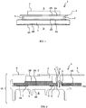
- FIG. 1 is a greatly simplified sectional view of a first embodiment of a control arrangement 1.
- the control arrangement 1 is suitable for regulating or controlling a compressor device which has a housing for a compressed fluid and wherein the fluid is compressed with the aid of an electric drive.
- the control arrangement 1 couples electronic components, such as an electrical power module 3 and conductor tracks (not shown), via a cooling plate 2 to an in particular elastically deformable structural element 4 of the compressor device with the aid of spacer elements 5, which distance the cooling plate 2 from the surface 4A of the structural element 4.
- the structural element 4 is, for example, a housing bottom of a compressor housing for receiving compressed fluid.
- the compressor device can be used, for example, in an electric or hybrid vehicle and with a voltage of 100 to 400 volts or 400 to 1000 volts can be operated. The range of use is preferably above the low voltage.
- the cooling plate 2 can alternatively be designed as a holding plate for electronic components and / or a circuit board of an electronic control device for the compressor drive.
- Fig. 1 one recognizes the deformable structural element 4, which has a flat geometry and can be, for example, the housing bottom of a compressor device.
- The, in particular elastically deformable, structural element 4 is arranged between an atmospheric pressure area P and a low pressure area N and separates them from one another.
- the low-pressure area N has a higher pressure than atmospheric pressure during the operation of the compressor device under consideration.
- the cooling plate 2 has an underside 2A and an upper side 2B, the cooling plate 2 being thermally coupled to the electric power module 3 at the upper side 2B for dissipating heat from the latter.
- the structural element 4 likewise has a top side 4A, which faces the bottom side 2A of the printed circuit board 6, the spacer elements 5 being located between the bottom side 2A and the top side 4A, and a bottom side 4B, which faces the printing area N. Due to the pressure difference, the structural element 4 can bulge or deform from an initial position. This is indicated by the dashed illustration of the top 4A 'and bottom 4B'.
- the cooling plate 2, the electrical power module 3 and the spacer elements 5 are not deformed, arched or deformed and are indicated by dashed outlines in order to illustrate the behavior of the control arrangement 1 during the deformation or arching of the structural element 4.
- a fastening arrangement for the cooling plate 2 with the plurality of spacer elements 5 is provided, which spaced the cooling plate 2 from the structural element 4, the spacer elements 5 being arranged in such a way that a transfer of the deformation or Curvature of the structural element 4 on the cooling plate 2 is largely prevented but at least reduced.
- the Spacer elements 5 are arranged, for example, around a deformation, a curvature, a curvature high point or curvature center point, that they move the cooling plate 2 preferably only translationally during the corresponding movement due to the deformation and the cooling plate 2 is not subjected to any additional bending or tension.
- the spacing of the control arrangement 1 is designed in such a way that with maximum deformation, deformation, shaping or bending of the structural element 4, for example during operation of the compressor device, no additional pressure point arises between the structural element 4 and the cooling plate 2.
- control arrangement 1 in a compressor arrangement, such as an air conditioning compressor for motor vehicles.
- FIGS. 2-7 show several representations of an embodiment for a compressor device 23 with a control arrangement in which a cooling plate is fastened as a holding plate with the aid of a fastening arrangement.
- a section of a compressor device 23 is shown in cross section.
- the Fig. 4 shows essentially a plan view of a housing base top
- Fig. 5 a perspective view of a thermal pad
- Fig. 6 shows part of the compressor device from an oblique perspective view of the top of the cooling plate.
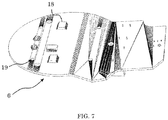
- the Fig. 7 Figure 3 is a perspective view of a circuit board.
- FIG. 4 shows a simplified sectional view of a second embodiment of the control arrangement 1.
- the control arrangement 1 comprises a heat-conducting element 7, which is arranged between the structural element 4 and the cooling plate 2, so that heat can be dissipated from the cooling plate 2 to the structural element 4 with the aid of the heat-conducting element 7.
- the heat-conducting element 7 has a flat geometry with a centrally arranged recess, so that a region of the structural element 4 that experiences the greatest deformation is arranged in the region of the recess.
- heat-conducting element 7 has recesses through which the spacer elements 5 extend, which are molded onto the structural element 4, so that a one-piece integral body 4, 5 composed of structural element 4 and spacer elements 5 is present.
- the top of the integral body 4, 5 is at least partially designed as a negative shape of the heat-conducting element 7.
- control arrangement 1 has at least one spring element 8, with the aid of the spring element 8 a pressing force being applied from the cooling plate 2 via the spacer elements 5 to the structural element 4.
- the spring element 8 is in particular a disc spring and rests on an upper side 2B of the cooling plate 2, the structural element 4 having at least one screw-on dome 9 which extends into a continuous opening 10 of the cooling plate 2, with a fixing element 11, in particular a disk, by means of a screw 12 is screwed onto the screw-on dome 9 and engages behind the cooling plate 2, the spring element 8 being pretensioned against the cooling plate 2 and against the fixing element 11.
- Both the screw-on dome 9 and the fixing element 11 have radial play within the, in particular, circular opening 10, so that slight displacements or movements of the screw-on dome 9 radially to the opening 10 do not induce any stresses in the cooling plate 2.
- the provision of a plurality of screw-on domes 9 would allow, in particular, slight lateral movements between the structural element 4 and the cooling plate 2.
- the cooling plate 2 is pretensioned in the direction of the structural element 4, so that a pressure or displacement of the spacer elements 5 due to a deformation, deformation, shaping or bending of the structural element 4 is compensated for by means of the spring element 8 or the spring elements 8 being compressed can be.
- the bias also ensures that the cooling plate 2 rests on the spacer elements 5 in a stable manner, in particular that there is no axial play between the cooling plate 2 and the spacer elements 5.
- the heat-conducting element 7 consists in particular of a more flexible material than the structural element 4 and / or the cooling plate 2 and / or is in particular a heat-conducting pad.
- the heat-conducting element 7 preferably consists of a flexible and / or elastic material.
- Fig. 3 shows the control arrangement according to Fig. 2 in a perspective view.
- the heat-conducting element 7 is mounted as a heat-conducting pad between the cooling plate 2 and the housing base 4.
- the heat-conducting element 7 requires a defined distance from the housing base 4, which is filled by the material of the heat-conducting pad 7.
- the housing bottom 4 is cooled by the refrigerant in the pressure chamber N.
- Fig. 4 shows a top view of a structural element 4 with a heat-conducting element 7.
- Three spacer elements 5 and three screw-on domes 9 are arranged on the structural element 4 around a center point M at an angular distance of 120 °.
- the spacer elements 5 are distributed symmetrically around the center of the deflection of the structural element 4, in particular the housing base.
- the heat-conducting element 7 has been cut out, since at this point 15 the up and down movement of the structural element 4, in particular the housing base, is greatest due to the changing pressure load.
- the structural element 4 or the housing base has four fixing elements 22, which are arranged radially outside at an angular distance of 90 ° and are provided as a positioning aid for the cooling plate 2, which has openings 21 corresponding to the fixing elements 22.
- the fixing elements 22 are designed in particular as fixing spikes and extend in the axial direction, that is to say essentially normal to the cooling plate 2 in the installed position.
- FIG. 11 shows a perspective view of the heat conducting element 7 from FIG Fig. 4 .
- the heat conducting element 7 has an annular geometry.
- the heat-conducting element 7 has recesses (only one of which is provided with reference numeral 16) for the cylindrical spacer elements 5 and at least partially for the cylindrical screw-on domes 9.
- the recesses 16 for the spacer element 5 have an angular spacing of 120 ° from one another.
- the recesses 17 for the screw-on domes 9 also have an angular spacing of 120 ° and each correspond in the radial direction to a recess 16 for one of the spacer elements 5, but lie radially further outward.
- Fig. 6 shows a perspective view of a cooling plate 2 with an electronic IGBT power module 3.
- the electrical power module 3 is mounted on the cooling plate 2 with the aid of a screw connection 13 and tabs 20.
- four screw-on domes 14 are provided for fastening the printed circuit board 6 to the cooling plate 2.
- the openings 21 are at least partially designed as a negative shape of the fixing elements 22, so that the cooling plate 2 can rest on the structural element 4 in a form-fitting and twist-proof manner as soon as the fixing elements 22 engage in the openings 21.
- the openings 21 are designed as elongated holes.
- Fig. 7 shows a perspective view of a circuit board 6.
- the circuit board 6 is mounted over the electrical power module 3 and is in contact with it.
- the electrical power module 3 is to the circuit board 6, for example a Circuit board or printed circuit as a carrier for electronic components 18 of the corresponding control circuit connected.
- To the screw connection 14 (cf. Fig. 6 ) 6 handling openings 20 are provided in the circuit board.
- the control circuit or control device for the corresponding air conditioning compressor is implemented on a printed circuit board 6 with the aid of electronic components 18, in particular with the aid of power semiconductors 3.
- the circuit board or circuit board 6 has in the illustration of Fig. 7 electrical components 9 on the upper side.
- the power semiconductors or modules 2 covered, which can develop temperatures between 100 and 150 ° C., are arranged on the underside.
- the present invention has been described on the basis of a few exemplary embodiments, it can be modified.
- the number of spacer elements can be varied. It is also possible to achieve the pressing force by other, for example, resilient elements.
- the shape and geometry of the housing base is not necessarily circular. Oval or other shapes are also conceivable.
- the structural element does not necessarily have to be a housing bottom of the compressor device.
- the materials and dimensions mentioned are variable and can be adapted to the respective installation situation of a structural element or a compressor device.
- the pressure specifications can also vary and depend on the refrigerant compressed with the aid of the compressor device.
Landscapes
- Engineering & Computer Science (AREA)
- Mechanical Engineering (AREA)
- General Engineering & Computer Science (AREA)
- Cooling Or The Like Of Electrical Apparatus (AREA)
Description
- Die vorliegende Erfindung betrifft eine Ansteueranordnung zum Regeln oder Steuern einer Kompressorvorrichtung, eine Befestigungsanordnung sowie eine Kompressorvorrichtung mit einer Ansteueranordnung. Außerdem betrifft die vorliegende Erfindung ein Verfahren zum Ansteuern einer Kompressorvorrichtung.
- Bei einem Kompressor oder Verdichter werden in der Regel Gase zu Fluiden verdichtet, welche in verschiedenen Prozessen weiterverwendet werden. Beispielsweise werden in der Kälte- und Klimatechnik bestimmte Kältemittel wie CO2 eingesetzt, die im Kreislauf verdichtet werden. Insbesondere bei in Kraftfahrzeugen eingesetzten Klimakompressoren erfolgt die Verdichtung mit Hilfe eines elektrischen Antriebs. Um einen im Kraftfahrzeug begrenzt vorhandenen Bauraum günstig zu nutzen, ist es dabei wünschenswert, Ansteuerschaltungen, insbesondere auch Platinen oder Leiterplatten, welche eine entsprechende Ansteuerelektronik tragen, mit dem Kompressorgehäuse zu verbinden oder zu integrieren.
- Eine Schwierigkeit dabei besteht zum Beispiel darin, dass sich aufgrund von Druckschwankungen Gehäuseflächen des Kompressors verbiegen oder bewegen können. Auf die mechanischen und elektronischen Elemente der Ansteuerelektronik sollte dabei möglichst keine Biegebeanspruchung übertragen werden.
- Die
US 2012/0113603 A1 offenbart eine elektrische Einrichtung mit einer Leiterkarte, einem Halbleiterbaustein, einem Gehäuse, mehreren Gummihülsen unter der Leiterkarte, eine Aluminiumplatte oberhalb der Leiterplatte und eine Isolierfolie. Durch die zwischen der Leiterplatte und dem Gehäuse angeordneten Gummihülsen werden die außenliegende Aluminiumplatte, die Isolierfolie, der Halbleiterbaustein und die Leiterplatte vertikal im zusammengebauten Zustand miteinander verspannt. - Vor diesem Hintergrund besteht die Aufgabe der vorliegenden Erfindung darin, eine günstige Befestigungsmöglichkeit für eine elektronische Ansteuereinrichtung für eine Kompressorvorrichtung an einer verformbaren Fläche zu schaffen.
- Diese Aufgabe wird durch eine Anordnung mit den Merkmalen des unabhängigen Anspruchs 1 und ein Verfahren nach Anspruch 15 gelöst.
- Demgemäß wird eine Ansteueranordnung zum Regeln oder Steuern einer Kompressorvorrichtung, welche ein Gehäuse für ein komprimiertes Fluid aufweist, vorgeschlagen. Ein verformbares Strukturelement des Gehäuses ist zwischen einem ersten Druckbereich und einem zweiten Druckbereich der Kompressorvorrichtung angeordnet. Die Ansteueranordnung umfasst ein elektrisches Leistungsmodul, eine Kühlplatte zum Ableiten von Wärme von dem elektrischen Leistungsmodul, welches thermisch an die Kühlplatte gekoppelt ist, und eine Befestigungsanordnung für die Kühlplatte. Die Befestigungsanordnung hat mehrere Abstandselemente, die die Kühlplatte von dem Strukturelement beabstanden, wobei die Abstandselemente derart angeordnet sind, dass eine Übertragung der Verformung des Strukturelements auf die Kühlplatte reduziert, insbesondere unterbunden, wird.
- Das Leistungsmodul ist insbesondere Teil einer elektronischen Ansteuereinrichtung für die Kompressorvorrichtung. Die Ansteuereinrichtung kann dabei weitere elektronische Bauelemente, wie Leistungshalbeiter, Schalter, Prozessoren, Speicher und dergleichen umfassen. Die elektronische Ansteuereinrichtung weist in Ausführungsformen Leiterkarten oder Platinen mit Leiterbahnen auf, die mit Hilfe der Befestigungsanordnung und der Kühlplatte vor Biegebeanspruchungen einerseits und thermischen Beanspruchungen andererseits geschützt werden.
- Vorzugsweise ist die Kühlplatte derart mit Hilfe der Abstandselemente von dem Strukturelement beabstandet, dass auch bei einer bei bestimmungsgemäßem Betrieb der Kompressorvorrichtung maximaler Verformung beziehungsweise Wölbung des Strukturelements kein zusätzlicher Kraftangriffspunkt zwischen Strukturelement und Kühlplatte entsteht. Dies hat den Vorteil, dass die Kühlplatte - und weitere daran mechanisch gekoppelte Elemente - keiner zusätzlichen Biegebeanspruchung ausgesetzt ist. Eine Verformung in der Art einer Wölbung des beispielsweise flächigen Strukturelements wird dann nicht auf die Kühlplatte übertragen, denn die Verformung der Strukturelementfläche in axialer Richtung kann zwischen den Positionen der Abstandselemente als Ausweichbewegung geschehen, ohne dass zusätzliche Spannungen in der Kühlplatte erzeugt werden. Dabei ist die Kühlplatte in Richtung der Ausweichbewegung vorzugsweise frei von unelastischen Hindernissen. Die Ansteueranordnung ist insofern robust und aufwandsgünstig in oder an das Gehäuse der Kompressorvorrichtung integriert.
- Der erste Druckbereich ist zum Beispiel ein Niederdruckbereich eines Kompressors, und der zweite Druckbereich ist ein Bereich mit Atmosphärendruck. Das Strukturelement kann beispielsweise einem Gehäuseboden entsprechen, der sich aufgrund von Druckschwankungen zwischen dem im Inneren des Kompressors vorliegenden Drucks und dem äußeren Atmosphärendruck verformt, ausformt, deformiert, wölbt oder biegt. Zum Beispiel wird im Betrieb der Kompressorvorrichtung ein Druckwechsel innerhalb des Gehäuses von 3 MPa auf 8,5 MPa bzw. 30 bar auf 85 bar, herbeigeführt. Der Bereich des Strukturelements oder des Gehäusebodens, der sich aufgrund von wechselnder Druckbelastung verformt, ausformt, deformiert, wölbt oder biegt, kann auch "atmender Bereich" genannt werden.
- Weiterhin ist beispielsweise der Druck im Niederdruckbereich bei der Befüllung des Kompressors mit einem Kältemittel nahezu Null, sodass das Strukturelement oder der Gehäuseboden sich auch in die "andere Richtung" bzw. nach innen verformen, ausformen, deformieren, wölben oder biegen kann, da der Atmosphärendruck höher ist. Dagegen kann der Niederdruckbereich beispielsweise mit einem Prüfdruck von 150 MPa bzw. 15 bar beaufschlagt werden.
- Bei der Ansteueranordnung ist die Kühlplatte insbesondere in axialer Richtung, also im Wesentlichen normal zur Kühlplatte und der Fläche des Strukturelements, vorzugsweise ausschließlich durch die Abstandselemente beabstandet. Eine Übertragung der Verformung des Strukturelements auf die Kühlplatte wird dabei zumindest gegenüber einer flächigen Befestigung der Kühlplatte an dem Gehäuse reduziert oder unterbunden.
- Die Kühlplatte kann insbesondere lateral relativ zu den Abstandselementen insbesondere leicht beweglich angeordnet sein. Unter "lateral" kann man in der Ebene der Kühlplatte verlaufend verstehen. Die Ansteueranordnung kann derart ausgestaltet sein, dass eine lateral schwimmende Halterung der Kühlplatte möglich ist. Das heißt, es kommt zu keinen Verspannungen in der Ebene der Kühlplatte.
- Die Kühlplatte und das insbesondere flächige Strukturelement verlaufen vorzugsweise parallel zueinander. Weiterhin ist die Kühlplatte vorzugsweise eine Aluplatte, Aluniniumoxidplatte, Keramikplatte, Kupferplatte, DCB-Platte (englisch: Direct Bonded Copper - DCB) oder Laminatplatte. Das elektrische Leistungsmodul ist vorzugsweise ein Modul mit Bipolartransistor mit isolierter Gate-Elektrode (englisch: insulated-gate bipolar transistor - IGBT) und/oder Metall-Oxid-Halbleiter-Feldeffekttransistor.
- Somit kann die Lebensdauer der Kühlplatte und der elektronischen Bauteile und Leiterbahnen deutlich verlängert werden. Bevorzugt sind die Abstandselemente derart um ein Wölbungs- beziehungsweise Deformationszentrum angeordnet, dass die Abstandselemente während des Wölbens oder Deformierens des Strukturelements symmetrisch bewegt werden, sodass die Kühlplatte lediglich eine translatorische Bewegung erfährt. Die Abstandselemente dienen als punktförmige Auflagepunkte für die Kühlplatte. Vorzugsweise sind die Abstandselemente an einer Stelle, an der die geringste Verformung des Strukturelements zu erwarten ist, angeordnet.
- Die als Kühlplatte ausgebildete Halteplatte ist vorzugsweise aus einem elektrisch leitenden Material gefertigt, sodass neben der Funktion der Halterung und Wärmeabfuhr ferner eine elektrische Abschirmung erfolgt. Die Ansteueranordnung genügt damit auch Sicherheitsanforderungen für Ansteuerelektroniken in Kraftfahrzeugen, die bei 12, 48 Volt oder mehr als Kleinspannung (bis zu 60 Volt), betrieben werden.
- Die Abstandselemente sind vorzugsweise symmetrisch um einen Bereich einer größten axialen oder normalen Auslenkung des Strukturelements herum angeordnet. Durch die mehreren beispielsweise symmetrisch vorgesehenen Abstandselemente wird insbesondere im Bereich der Abstandselemente ein vorgegebener Abstand zwischen der Kühlplatte und dem Strukturelement konstant gehalten. Dies ermöglicht den Einsatz von flachen Wärmeleitelementen, die eine besonders gute Wärmeübertragung von der Kühlplatte zu dem Strukturelement realisieren können.
- In Ausführungsformen ist das elektrische Leistungsmodul zum Abführen von Wärme von dem elektrischen Leistungsmodul an die Kühlplatte auf einer dem Strukturelement abgewandten Seite angeordnet.
- Somit ist zwischen Leistungsmodul und Strukturelement zumindest die Kühlplatte angeordnet. Folglich kann das Abführen von Wärme hin zum Strukturelement mit Hilfe der Kühlplatte verwirklicht werden, ohne dass Wölbungen beziehungsweise Verformungen des Strukturelements das Leistungsmodul mechanisch beeinflussen.
- In Ausführungsformen umfasst die Ansteueranordnung mindestens ein Wärmeleitelement, das zwischen dem Strukturelement und der Kühlplatte angeordnet ist, sodass Wärme von der Kühlplatte an das Strukturelement mit Hilfe des Wärmeleitelements abführbar ist.
- Da das Wärmeleitelement zusätzlich zwischen Kühlplatte und Strukturelement angeordnet ist, verbessert dies die Kühlung des Leistungsmoduls. Vorzugsweise besteht das Wärmeleitelement aus einem flexibleren Material als die Kühlplatte und/oder das Strukturelement. Weiter bevorzugt ist das Wärmeleitelement elastisch und oder flexibel ausgestaltet.
- Das Wärmeleitelement ist beispielsweise zumindest teilweise aus einem Elastomer gefertigt. Weiterhin kann das Wärmeleitelement in Form eines Gels, Gelees oder einer Paste auf das Strukturelement aufgetragen werden. Dies kann beispielsweise mit Hilfe eines Dispensers erfolgen.
- In Ausführungsformen weist das Wärmeleitelement eine flächige Geometrie mit einer, insbesondere mittig angeordneten, Aussparung auf, sodass ein Bereich des Strukturelements, der die größte Verformung erfährt, im Bereich der Aussparung angeordnet ist.
- Die größte Verformung kann vorliegend auch als größte Ausformung, Wölbung oder Deformation verstanden werden. Mit Hilfe der Aussparung wird Platz für das Strukturelement geschaffen, das sich bei der Verformung, Deformation oder Wölbung in die Aussparung hinein erstrecken kann. Folglich wird auch eine Übertragung der Verformung des Strukturelements auf das Wärmeleitelement unterbunden oder gering gehalten. Dies hat den Vorteil, dass das Wärmeleitelement schonend eingesetzt wird. Weiter bevorzugt sind Verdrängungsräume vorgesehen, sodass das Wärmeleitelement, das aufgrund der Deformation des Strukturelements gequetscht wird, Platz zum Ausweichen hat. Dies kann beispielsweise durch eine Unterteilung des Wärmeleitelements oder Schaffung zusätzlicher Zwischenräume verwirklicht werden. Vorzugsweise erstreckt sich ein Teil des Strukturelements in die Aussparung.
- In Ausführungsformen weist das Wärmeleitelement Aussparungen auf, durch die sich die Abstandselemente erstrecken.
- Das Vorsehen der Aussparungen für die Abstandselemente im Wärmeleitelement ermöglicht den Einsatz eines großen Wärmeleitelements, welches beispielsweise länger und/oder breiter ist als ein Abstand zwischen den Abstandselementen. Gleichzeitig kann auch mit Hilfe der Aussparungen eine Verdrehsicherung für das Wärmeleitelement relativ zum Strukturelement verwirklicht werden. Vorzugsweise erstrecken sich die Abstandselemente durch die Aussparungen bis hin zur Kühlplatte.
- Das oder die Wärmeleitelemente können in der Art von Pads zwischen der Kühlplatte und dem in der Regel flachen Strukturelement vorliegen. Die mit einer Anpresskraft beaufschlagten Abstandselemente gewährleisten dadurch eine im Wesentlichen konstante Beabstandung, so dass jedenfalls im Bereich beispielsweise um die Abstandselemente herum ein Kontakt zwischen dem Pad und der Halteplatte oder Kühlplatte einerseits, und dem Gehäuseboden bzw. Strukturelement andererseits, gewährleistet ist.
- In Ausführungsformen hat der Gehäuseboden eine oder mehrere Ausnehmungen zur Aufnahme von einem oder mehreren Wärmeleitelementen.
- In Ausführungsformen weist die Ansteueranordnung zumindest ein Federelement auf, wobei mit Hilfe des Federelements eine Anpresskraft von der Kühlplatte über die Abstandselemente auf das Strukturelement aufgebracht wird.
- Beispielsweise ist das Federelement als Elastomerfeder, insbesondere mit einer flächigen Geometrie, ausgebildet. Dabei kann das Federelement insbesondere an der Innenseite eines Gehäusedeckels angeordnet sein und die Anpresskraft auf den Rest der Ansteueranordnung ausüben.
- Vorzugsweise sind mehrere Federelemente, insbesondere wenigstens drei, vorgesehen. Beispielsweise ist ein Federelement an einem Befestigungsmittel vorgesehen, welches die Kühlplatte mit dem Strukturelement befestigt. Das Federelement ist insbesondere eine Tellerfeder und liegt auf einer Oberseite der Kühlplatte auf, wobei das Strukturelement insbesondere zumindest einen Anschraubdom aufweist, der sich insbesondere in eine durchgängige Öffnung der Kühlplatte erstreckt, wobei insbesondere ein Fixierelement, z.B. eine Scheibe, mit Hilfe eines Befestigungsmittels, z.B. einer Schraube oder einem Bolzen, an den Anschraubdom angeschraubt ist und die Kühlplatte hintergreift, wobei das Federelement gegen die Kühlplatte und das Fixierelement vorgespannt ist.
- Alternativ oder zusätzlich wird die Kühlplatte mit Hilfe einer axialen Anpresskraft gehalten, welche insbesondere mit Hilfe eines verschraubbaren oder verrastbaren Deckels der Kompressorvorrichtung, der an das Strukturelement lösbar befestigt wird, erzeugt ist. Eine axiale Anpresskraft kann insbesondere über weitere Haltemittel übertragen werden.
- Sowohl der Anschraubdom als auch das Fixierelement weisen insbesondere ein radiales Spiel innerhalb der insbesondere kreisrunden Öffnung der Kühlplatte auf, sodass leichte Verschiebungen oder Bewegungen des Anschraubdoms radial zur Öffnung keine Spannungen in die Kühlplatte induzieren. Somit würde das Vorsehen auch mehrerer Anschraubdome insbesondere geringförmige laterale Bewegungen zwischen dem Strukturelement und der Kühlplatte zulassen. Mit Hilfe des vorgespannten Federelements wird die Kühlplatte in Richtung des Strukturelements vorgespannt, sodass insbesondere ein Drücken oder eine Verschiebung von den Abstandselementen aufgrund einer Deformation, Verformung, Ausformung oder Verbiegung des Strukturelements mittels Einfedern des Federelements bzw. der Federelemente ausgeglichen werden kann. Die Vorspannung stellt gleichermaßen sicher, dass ein stabiles Aufliegen der Kühlplatte auf den Abstandselementen gewährleistet ist, insbesondere kein axiales Spiel zwischen der Kühlplatte und den Abstandselementen vorherrscht. Das Federelement ist insbesondere so auszuführen, dass es die Auf- und Abbewegung der Kühlplatte ausgleichen kann.
- In Ausführungsformen bildet das Strukturelement eine, insbesondere kreisförmige, Fläche aus und sind die Abstandselemente symmetrisch um einen geometrischen Mittelpunkt der Fläche angeordnet.
- Vorzugsweise sind die Abstandselemente zum Beabstanden der Kühlplatte im Randbereich der Kühlplatte und der insbesondere kreisförmigen Fläche des Strukturelements vorgesehen. Beispielsweise können die Abstandselemente in regelmäßigen Winkelabständen, insbesondere 120°, um den Mittelpunkt vorgesehen werden. Somit kann eine stabile Auflagefläche der Kühlplatte auf den Abstandselementen verwirklicht werden. Vorzugsweise ist der geometrische Mittelpunkt der Punkt, der eine maximale Ausformung bei der Deformation beziehungsweise Wölbung des Strukturelements erfährt.
- In Ausführungsformen sind die Abstandselemente wenigstens abschnittsweise zylinderförmig ausgebildet.
- Es können beispielsweise Kreiszylinder mit einer Höhe zwischen 0,1 und 2 mm vorgesehen werden. Die Höhe der Abstandselemente gibt zumindest einen Abstand der Kühlplatte zu dem Strukturelement vor.
- In Ausführungsformen sind die Abstandselemente an dem Strukturelement angeformt.
- Es liegt dann ein Integralkörper aus Strukturelement und Abstandselementen vor. Bevorzugt besteht der Integralkörper aus einem Material. Weiter bevorzugt ist der Integralkörper gegossen und/oder mit Hilfe von zerspanenden Fertigungsverfahren hergestellt. Folglich müssen die Abstandselemente nicht in einem aufwendigen Montageprozess positioniert, ausgerichtet oder befestigt werden.
- In Ausführungsformen sind die Abstandselemente an der Kühlplatte angeformt. Dann liegt ein Integralkörper aus Abstandselementen und Kühlplatte vor.
- Es wird insbesondere eine Befestigungsanordnung für eine Kühlplatte an einem verformbaren Strukturelement vorgeschlagen, welches zwischen einem ersten Druckbereich und einem zweiten Druckbereich einer Kompressorvorrichtung angeordnet ist, wobei die Kühlplatte zum Ableiten von Wärme von einem elektrischen Leistungsmodul, welches thermisch an die Kühlplatte gekoppelt ist, eingerichtet ist, wobei mit Hilfe von mehreren Abstandselementen die Kühlplatte von dem Strukturelement beabstandet ist, wobei die Abstandselemente derart angeordnet sind, dass eine Übertragung der Verformung des Strukturelements auf die Kühlplatte unterbunden wird.
- Es wird darüber hinaus eine Kompressorvorrichtung vorgeschlagen mit einer Ansteueranordnung, wie sie vorstehend oder im Folgenden beschrieben ist, einem Gehäuseteil, welches einen Gehäuseboden als Strukturelement umfasst, wobei der Gehäuseboden einen ersten Druckbereich von einem zweiten Druckbereich, welcher einen niedrigeren Druck hat als der erste Druckbereich, trennt, wobei die Kühlplatte niederdruckseitig an dem Gehäuseboden in axialer Richtung mit Hilfe der Befestigungsanordnung befestigt ist.
- Die Druckdifferenz kann zum Beispiel zwischen 3 und 8,5 MPa betragen, sodass bei einem Kompressor der Gehäuseboden um einige zehntel Millimeter bei einem Betrieb gewölbt werden kann. Ein Durchbiegen der Kühlplatte wird allerdings durch die Ansteueranordnung oder Befestigungsanordnung vermieden. Die Kompressorvorrichtung ist beispielsweise dazu eingerichtet, CO2 oder FCKW (Fluorchlorkohlenwasserstoff) zu verdichten. In Ausführungsformen handelt es sich insofern um einen Kühlkompressor für CO2 als Kühlmittel,
- In Ausführungsformen hat der Gehäuseboden eine Positionierhilfe, eine Zentriereinrichtung und/oder eine Verdrehsicherung für die Kühlplatte. Dadurch wird die Fertigung und Herstellung der Kompressorvorrichtung vereinfacht. Weiterhin wird eine schwimmende Befestigung ermöglicht, bei der insbesondere eine laterale Bewegung relativ zu den Abstandselementen ermöglicht ist.
- In Ausführungsformen hat die Kompressorvorrichtung einen Niederdruckbereich zum Sammeln von zu verdichtendem Fluid und einen Hochdruckbereich, in dem verdichtetes oder komprimiertes Fluid vorgehalten wird. In Ausführungsformen grenzt das Strukturelement als Gehäuseboden den Niederdruckbereich von dem Außerhalb der Kompressorvorrichtung vorliegenden Atmosphärendruck ab. In der Niederdruckkammer ist das Fluid meist deutlich kühler als im Hochdruckbereich, sodass der Gehäuseboden besser als bei einer Anordnung der Kühlplatte an einer dem Hochdruckbereich begrenzenden Gehäusewand der Kühlung dienen kann.
- Es wird ferner ein Verfahren zum Befestigen einer Kühlplatte an einem verformbaren Strukturelement, welches zwischen einem Hochdruckbereich und einem Niederdruckbereich einer Kompressorvorrichtung angeordnet ist, vorgeschlagen. Dabei wird die Kühlplatte mit Hilfe von Abstandselementen von dem Strukturelement beabstandet. Das Verfahren nutzt insbesondere eine Ansteueranordnung, wie vorstehend beschrieben, oder eine Befestigungsanordnung, wie vorstehend beschrieben, oder eine Kompressorvorrichtung, wie vorstehend beschrieben.
- In Ausführungsformen ist das Strukturelement dazu eingerichtet, dass es sich aufgrund eines Druckanstiegs in Bereichen, in denen die Abstandselemente angeordnet sind, weniger von einem Nullniveau wegbewegt, als in einem Bereich zwischen den Abstandselementen. Beispielsweise wölbt sich das Strukturelement in einem Bereich zwischen den Abstandselementen aufgrund eines Druckanstiegs.
- In Ausführungsformen umfasst die Ansteueranordnung, Befestigungsanordnung oder Kompressorvorrichtung eine Leiterplatte, insbesondere eine Leiterkarte. Das Leistungsmodul kann zwischen der Kühlplatte und der Leiterplatte angeordnet sein aber auch auf der der Kühlplatte und dem Strukturelement abgewandten Seite der Leiterplatte. Somit wird auch eine Übertragung der Verformung des Strukturelements auf die Leiterplatte mit Hilfe der Kühlplatte und deren Befestigung unterbunden.
- In Ausführungsformen ist insbesondere am Mittelpunkt oder einem vorgegebenem Bereich um den Mittelpunkt herum, der häufig einer besonders starken axialen Auslenkung durch eine Verformung des Strukturelementes ausgesetzt ist, kein Abstandselement zum Befestigen der Kühlplatte vorgesehen. In alternativen Ausführungsformen der Befestigungsanordnung und/oder der Ansteueranordnung, die nicht erfindungsgemäß sind und die nur zur Veranschaulichung dienen, wird die Kühlplatte durch eine Halteplatte ersetzt. Dann hat die Halteplatte nur optional eine wärmeableitende Funktion und dient hauptsächlich als Halte- oder Trägerelemente für die elektronischen Bauteile und/oder eine Leiterplatte oder Platine.
- In einer Ausführungsform hat der Gehäuseboden eine druckdichte Durchführung für wenigstens eine Anschlussleitung von dem ersten Druckbereich zu dem zweiten Druckbereich an die Halteplatte oder Kühlplatte.
- Vorzugsweise liegen keine weiteren Befestigungsmittel vor, so dass auch bei einer Verformung des Strukturelementes die Halteplatte oder Kühlplatte praktisch immer ihre ebene Form beibehält. Man kann sagen, die Halteplatte oder Kühlplatte wird an dem insbesondere flachen Strukturelement schwimmend gehalten oder gelagert.
- In Ausführungsformen ist das Strukturelement beispielsweise als ein Gehäuseboden eines Klimakompressors ausgeführt, der aus einem gut wärmeleitfähigen Material gefertigt ist. Denkbar ist zum Beispiel ein Aluminiummaterial, Edelstahl oder auch ein Verbundwerkstoff. Ferner kann das Strukturelement zusätzlich eine Kühlfunktion haben, weil im zweiten Druckbereich vorliegendes Kältemittel meist unterhalb der Betriebstemperaturen der Leistungshalbleiter ist. Leitungshalbleiterchips entwickeln beispielsweise Temperaturen zwischen 100 und 150 °C, während das Kältemittel im Kompressor deutlich unter 60°C hat.
- Die für die vorgeschlagene Ansteueranordnung beschriebenen Ausführungsformen und Merkmale gelten für die vorgeschlagene Befestigungsanordnung, die vorgeschlagene Kompressorvorrichtung und das vorgeschlagene Verfahren entsprechend. Ebenso gelten die Ausführungsformen und Merkmale der vorgeschlagenen Kompressorvorrichtung für die Befestigungsanordnung, Ansteueranordnung und das Verfahren.
- Weitere mögliche Implementierungen der Erfindung umfassen auch nicht explizit genannte Kombinationen von zuvor oder im Folgenden bezüglich der Ausführungsbeispiele beschriebenen Merkmale oder Ausführungsformen. Dabei wird der Fachmann auch Einzelaspekte als Verbesserungen oder Ergänzungen zu der jeweiligen Grundform der Erfindung hinzufügen.
- Weitere vorteilhafte Ausgestaltungen und Aspekte der Erfindung sind Gegenstand der Unteransprüche sowie der im Folgenden beschriebenen Ausführungsbeispiele der Erfindung. Im Weiteren wird die Erfindung anhand von bevorzugten Ausführungsformen unter Bezugnahme auf die beigelegten Figuren näher erläutert.
- Fig. 1
- zeigt eine stark vereinfachte Schnittansicht einer ersten Ausführungsform einer Ansteueranordnung;
- Fig. 2
- zeigt eine vereinfachte Schnittansicht einer zweiten Ausführungsform der Ansteueranordnung;
- Fig. 3
- zeigt die Ansteueranordnung gemäß
Fig. 2 in einer perspektivischen Darstellung; - Fig. 4
- zeigt eine Aufsicht eines Strukturelements mit einem Wärmeleitelement;
- Fig. 5
- zeigt eine perspektivische Ansicht eins Wärmeleitelements;
- Fig. 6
- zeigt eine perspektivische Ansicht einer Kühlplatte mit einem Leistungsmodul; und
- Fig. 7
- zeigt eine perspektivische Ansicht einer Leiterplatte.
- In den Figuren sind gleiche oder funktionsgleiche Elemente mit denselben Bezugszeichen versehen worden, sofern nichts anderes angegeben ist.
- In der
Fig. 1 ist eine stark vereinfachte Schnittansicht einer ersten Ausführungsform einer Ansteueranordnung 1. Die Ansteueranordnung 1 ist zum Regeln oder Steuern einer Kompressorvorrichtung geeignet, welche ein Gehäuse für ein komprimiertes Fluid aufweist und wobei das Fluid mit Hilfe eines elektrischen Antriebs verdichtet wird. Die Ansteueranordnung 1 koppelt über eine Kühlplatte 2 elektronische Bauteile, wie ein elektrisches Leistungsmodul 3 und Leiterbahnen (nicht dargestellt) an ein insbesondere elastisch verformbares Strukturelement 4 der Kompressorvorrichtung mit Hilfe von Abstandselementen 5, welche die Kühlplatte 2 von der Oberfläche 4A des Strukturelements 4 beabstanden. Das Strukturelement 4 ist zum Beispiel ein Gehäuseboden eines Kompressorgehäuses zur Aufnahme von komprimiertem Fluid. Die Kompressorvorrichtung kann beispielsweise in einem Elektro- oder Hybridfahrzug eingesetzt werden und mit einer Spannung von 100 bis 400 Volt oder 400 bis 1000 Volt betrieben werden. Vorzugsweise liegt der Einsatzbereich oberhalb der Kleinspannung. Die Kühlplatte 2 kann alternativ als Halteplatte für elektronische Bauteile und/oder eine Platine einer elektronischen Ansteuereinrichtung für den Kompressorantrieb ausgestaltet sein. - In
Fig. 1 erkennt man das verformbare Strukturelement 4, das eine flächige Geometrie aufweist und beispielsweise der Gehäuseboden einer Kompressorvorrichtung sein kann. Das, insbesondere elastisch verformbare, Strukturelement 4 ist zwischen einem Atmosphärendruckbereich P und einem Niederdruckbereich N angeordnet und trennt diese voneinander. Der Niederdruckbereich N hat beim Betrieb der betrachteten Kompressorvorrichtung einen höheren Druck als Atmosphärendruck. Die Kühlplatte 2 hat eine Unterseite 2A und eine Oberseite 2B, wobei die Kühlplatte 2 an der Oberseite 2B zum Ableiten von Wärme von dem elektrischen Leistungsmodul 3 thermisch an dieses gekoppelt ist. Genauso hat das Strukturelement 4 eine Oberseite 4A, welche der Unterseite 2A der Leiterplatte 6 zugewandt ist, wobei sich die Abstandselemente 5 zwischen der Unterseite 2A und der Oberseite 4A befinden, und eine Unterseite 4B, welche zum Druckbereich N gerichtet ist. Aufgrund der Druckdifferenz kann sich das Strukturelement 4 von einer Ausgangslage aus wölben oder verformen. Dies ist durch die gestrichelte Darstellung der Oberseite 4A' und Unterseite 4B' angedeutet. Die Kühlplatte 2, das elektrische Leistungsmodul 3 und die Abstandselemente 5 werden nicht deformiert, gewölbt oder verformt und sind durch gestrichelte Umrisse angedeutet, um das Verhalten der Ansteueranordnung 1 während der Deformation bzw. Wölbung des Strukturelements 4 zu illustrieren. - Damit die Kühlplatte 2 nicht derselben Verformung oder Wölbung ausgesetzt ist, ist eine Befestigungsanordnung für die Kühlplatte 2 mit den mehreren Abstandselementen 5 vorgesehen, die die Kühlplatte 2 von dem Strukturelement 4 beabstanden, wobei die Abstandselemente 5 derart angeordnet sind, dass eine Übertragung der Verformung oder Wölbung des Strukturelements 4 auf die Kühlplatte 2 weitgehend unterbunden aber zumindest reduziert wird. Die Abstandselemente 5 sind beispielsweise derart um eine Verformung, eine Wölbung, einen Wölbungshochpunkt oder Wölbungsmittelpunkt angeordnet, dass sie die Kühlplatte 2 während der entsprechenden Bewegung aufgrund der Deformation vorzugsweise nur translatorisch verschieben und die Kühlplatte 2 keiner zusätzlichen Biegung oder Verspannung ausgesetzt ist. Entsprechend ist die Ansteueranordnung 1 hinsichtlich der Beabstandung derart ausgelegt, dass bei maximaler Deformation, Verformung, Ausformung oder Verbiegung des Strukturelements 4, z.B. während des Betriebs der Kompressorvorrichtung, kein zusätzlicher Druckpunkt zwischen Strukturelement 4 und Kühlplatte 2 entsteht.
- Es ist insbesondere ein Einsatz der Ansteueranordnung 1 in einer Kompressoranordnung, wie einem Klimakompressor für Kraftfahrzeuge, möglich.
- Die
Fig. 2 - 7 zeigen mehrere Darstellungen einer Ausführungsform für eine Kompressorvorrichtung 23 mit einer Ansteueranordnung, bei der eine Kühlplatte als Halteplatte mit Hilfe einer Befestigungsanordnung befestigt ist. In derFig. 2 und3 ist ein Ausschnitt einer Kompressorvorrichtung 23 im Querschnitt dargestellt. DieFig. 4 zeigt im Wesentlichen eine Draufsicht auf eine Gehäusebodenoberseite,Fig. 5 eine perspektivische Ansicht eines Wärmeleitpads, und dieFig. 6 zeigt einen Teil der Kompressorvorrichtung von einer schrägen perspektivischen Ansicht auf die Oberseite der Kühlplatte. DieFig. 7 ist eine perspektivische Darstellung einer Platine. -
Fig. 2 zeigt eine vereinfachte Schnittansicht einer zweiten Ausführungsform der Ansteueranordnung 1. Im Unterschied zuFig. 1 umfasst die Ansteueranordnung 1 ein Wärmeleitelement 7, das zwischen dem Strukturelement 4 und der Kühlplatte 2 angeordnet ist, sodass Wärme von der Kühlplatte 2 an das Strukturelement 4 mit Hilfe des Wärmeleitelements 7 abführbar ist. Das Wärmeleitelement 7 weist eine flächige Geometrie mit einer mittig angeordneten Aussparung auf, sodass ein Bereich des Strukturelements 4, der die größte Verformung erfährt, im Bereich der Aussparung angeordnet ist. Weiterhin weist das Wärmeleitelement 7 Aussparungen auf, durch die sich die Abstandselemente 5 erstrecken, die an das Strukturelement 4 angeformt sind, sodass ein einstückiger Integralkörper 4, 5 aus Strukturelement 4 und Abstandselementen 5 vorliegt. Die Oberseite des Integralkörpers 4, 5 ist zumindest teilweise als Negativform des Wärmeleitelements 7 ausgebildet. - Ferner weist die Ansteueranordnung 1 zumindest ein Federelement 8 auf, wobei mit Hilfe des Federelements 8 eine Anpresskraft von der Kühlplatte 2 über die Abstandselemente 5 auf das Strukturelement 4 aufgebracht wird. Das Federelement 8 ist insbesondere eine Tellerfeder und liegt auf einer Oberseite 2B der Kühlplatte 2 auf, wobei das Strukturelement 4 zumindest einen Anschraubdom 9 aufweist, der sich in eine durchgängige Öffnung 10 der Kühlplatt 2 erstreckt, wobei ein Fixierelement 11, insbesondere eine Scheibe, mittels einer Schraube 12 an den Anschraubdom 9 angeschraubt ist und die Kühlplatte 2 hintergreift, wobei das Federelement 8 gegen die Kühlplatte 2 und gegen das Fixierelement 11 vorgespannt ist. Sowohl der Anschraubdom 9 als auch das Fixierelement 11 weisen ein radiales Spiel innerhalb der insbesondere kreisrunden Öffnung 10 auf, sodass leichte Verschiebungen oder Bewegungen des Anschraubdoms 9 radial zur Öffnung 10 keine Spannungen in die Kühlplatte 2 induzieren. Somit würde das Vorsehen mehrerer Anschraubdome 9 insbesondere geringförmige laterale Bewegungen zwischen dem Strukturelement 4 und der Kühlplatte 2 zulassen. Mit Hilfe des vorgespannten Federelements 8 wird die Kühlplatte 2 in Richtung des Strukturelements 4 vorgespannt, sodass ein Drücken oder eine Verschiebung von den Abstandselementen 5 aufgrund einer Deformation, Verformung, Ausformung oder Verbiegung des Strukturelements 4 mittels Einfedern des Federelements 8 bzw. der Federelemente 8 ausgeglichen werden kann. Die Vorspannung stellt gleichermaßen sicher, dass ein stabiles Aufliegen der Kühlplatte 2 auf den Abstandselementen 5 gewährleistet ist, insbesondere kein axiales Spiel zwischen der Kühlplatte 2 und den Abstandselementen 5 vorherrscht.
- In
Fig. 2 ist nur ein Abstandselement 5 dargestellt, wobei die anderen Abstandselemente 5 sich in anderen Querschnittsebenen der Ansteueranordnung 1 befinden bzw. in der dargestellten Ebene nicht zu sehen sind. Das Wärmeleitelement 7 besteht insbesondere aus einem flexibleren Material als das Strukturelement 4 und/oder die Kühlplatte 2 und/oder ist insbesondere ein Wärmeleitpad. Vorzugsweise besteht das Wärmeleitelement 7 aus einem flexiblen und/oder elastischen Material. -
Fig. 3 zeigt die Ansteueranordnung gemäßFig. 2 in einer perspektivischen Darstellung. - Um eine Beschädigung des elektrischen Leistungsmoduls 3 und der Leiterplatte bzw. Leiterkarte oder Platine 6 zu verhindern, wurden diese auf die Kühlplatte 2 montiert. Zwischen der Kühlplatte 2 und dem Gehäuseboden 4, ist das Wärmeleitelement 7 als ein Wärmeleitpad, montiert. Das Wärmeleitelement 7 benötigt einen definierten Abstand zum Gehäuseboden 4, der durch das Material des Wärmeleitpads 7 ausgefüllt ist. Dadurch wird die entstehende Wärme im elektrischen Leistungsmodul 3 oder von der Platine 6 über die Kühlplatte 2 auf den Gehäuseboden 4 übertragen. Der Gehäuseboden 4 ist durch das sich im Druckraum N befindliche Kältemittel gekühlt.
-
Fig. 4 zeigt eine Aufsicht eines Strukturelements 4 mit einem Wärmeleitelement 7. Es sind drei Abstandselemente 5 und drei Anschraubdome 9 am Strukturelement 4 um einen Mittelpunkt M in einem Winkelabstand von 120° angeordnet. Um eine gleichmäßige Auflage und Bewegung der Kühlplatte 2 mit dem Strukturelement 4, insbesondere dem Gehäuseboden, zu gewährleisten werden die Abstandselemente 5 symmetrisch um die Mitte der Durchbiegung des Strukturelements 4, insbesondere des Gehäusebodens, verteilt. In der Mitte des Strukturelements 4 wurde das Wärmeleitelement 7 ausgespart, da an dieser Stelle 15 die auf und ab Bewegung des Strukturelements 4, insbesondere des Gehäusebodens, aufgrund wechselnder Druckbelastung am größten ist. - Weiterhin weist das Strukturelement 4 oder der Gehäuseboden vier Fixierelemente 22 auf, die in einem Winkelabstand von 90° radial außen angeordnet und als Positionierhilfe für die Kühlplatte 2, die zu den Fixierelementen 22 korrespondierende Auslassungen 21 aufweist, vorgesehen sind. Die Fixierelemente 22 sind insbesondere als Fixierdorne ausgebildet und erstrecken sich in axiale Richtung, also im Wesentlichen normal zur Kühlplatte 2 in Einbaulage.
-
Fig. 5 zeigt eine perspektivische Ansicht des Wärmeleitelements 7 ausFig. 4 . Das Wärmeleitelement 7 weist eine kreisringförmige Geometrie auf. Weiterhin weist das Wärmeleitelement 7 Aussparungen (wovon nur eine mit Bezugszeichen 16 versehen ist) für die zylinderförmigen Abstandselemente 5 und zumindest teilweise für die zylinderförmigen Anschraubdome 9 auf. Die Aussparungen 16 für die Abstandselement 5 weisen einen Winkelabstand von 120° untereinander auf. Die Aussparungen 17 für die Anschraubdome 9 weisen ebenso einen Winkelabstand von 120° auf und korrespondieren in radialer Richtung jeweils mit einer Aussparung 16 für eines der Abstandselemente 5, liegen jedoch radial weiter außen. -
Fig. 6 zeigt eine perspektivische Ansicht einer Kühlplatte 2 mit einem elektronischen IGBT-Leistungsmodul 3. Das elektrische Leistungsmodul 3 ist mit Hilfe einer Schraubverbindung 13 und Laschen 20 an die Kühlplatte 2 montiert. Weiterhin sind vier Anschraubdome 14 für die Befestigung der Leiterplatte 6 an der Kühlplatte 2 vorgesehen. Die Auslassungen 21 sind zumindest teilweise als Negativform der Fixierelemente 22 ausgebildet, sodass die Kühlplatte 2 formschlüssig und verdrehsicher auf dem Strukturelement 4 aufliegen kann, sobald die Fixierelemente 22 in die Auslassungen 21 eingreifen. Die Auslassungen 21 sind als Langlöcher ausgebildet. -
Fig. 7 zeigt eine perspektivische Ansicht einer Leiterplatte 6. Die Leiterplatte 6 ist über das elektrische Leistungsmodul 3 montiert und mit diesem kontaktiert. Das elektrische Leistungsmodul 3 ist an die Leiterplatte 6, beispielsweise eine Platine oder gedruckte Schaltung als Träger für elektronische Bauteile 18 der entsprechenden Ansteuerschaltung, angeschlossen. Man spricht auch von einer Leiterkarte, Leiterplatte, Platine oder PCB (Englisch: Printed Circuit Board). Um die Schraubverbindung 14 (vgl.Fig. 6 ) zu erreichen sind in der Leiterplatte 6 Handhabungsöffnungen 20 vorgesehen. - Die Ansteuerschaltung oder Ansteuereinrichtung für den entsprechenden Klimakompressor ist auf einer Leiterplatine 6 mit Hilfe elektronischer Bauelemente 18 insbesondere mit Hilfe von Leistungshalbleitern 3 implementiert. Die Platine oder Leiterplatte 6 hat in der Darstellung der
Fig. 7 oberseitig elektrische Bauelemente 9. Ferner sind unterseitig die Leistungshalbleiter oder Module 2 (verdeckt) angeordnet, die Temperaturen zwischen 100 und 150°C entwickeln können. - Obwohl die vorliegende Erfindung anhand von einigen Ausführungsbeispielen beschrieben wurde, ist sie modifizierbar. Insbesondere kann die Anzahl der Abstandselemente variiert werden. Es ist ferner möglich, die Anpresskraft durch andere beispielsweise federnde Elemente zu erzielen. Ferner ist die Form und Geometrie des Gehäusebodens nicht zwangsläufig kreisförmig. Auch ovale oder andere Formen sind dabei denkbar. Bei dem Strukturelement muss es nicht unbedingt ein Gehäuseboden der Kompressorvorrichtung sein. Ferner sind die genannten Materialien und Abmessung variabel und können an die jeweilige Einbausituation eines Strukturelementes oder einer Kompressorvorrichtung angepasst werden. Die Druckangaben können ebenfalls variieren und hängen von dem mit Hilfe der Kompressorvorrichtung komprimierten Kältemittel ab.
-
- 1
- Ansteueranordnung
- 2
- Kühlplatte
- 2A
- Unterseite
- 2B
- Oberseite
- 3
- elektrisches Leistungselement
- 4
- Strukturelement
- 4A
- Oberseite
- 4B
- Unterseite
- 5
- Abstandshalter
- 6
- Leiterplatte
- 7
- Wärmeleitelement
- 8
- Federelement
- 9
- Anschraubdom
- 10
- Öffnung
- 11
- Fixierelement
- 12
- Schraube
- 13
- Schraubverbindung
- 14
- Anschraubdom
- 15, 16, 17
- Aussparung
- 18
- elektronisches Bauteil
- 19
- Handhabungsöffnung
- 20
- Befestigungslasche
- 21
- Auslassungen
- 22
- Fixierelemente
- 23
- Kompressorvorrichtung
- N
- Niederdruckbereich
- M
- Mittelpunkt
- P
- Atmosphärendruckbereich
Claims (16)
- Kompressorvorrichtung (23) umfassend:ein Gehäuse für ein komprimiertes Fluid, wobei ein verformbares Strukturelement (4) des Gehäuses zwischen einem ersten Druckbereich (N) und einem zweiten Druckbereich (P) der Kompressorvorrichtung (23) angeordnet ist, undeine Ansteueranordnung (1) zum Regeln oder Steuern der Kompressorvorrichtung (23), wobei die Ansteueranordnung (1) umfasst:ein elektrisches Leistungsmodul (3),eine Kühlplatte (2), die zum Ableiten von Wärme von dem elektrischen Leistungsmodul (3), welches thermisch an die Kühlplatte (2) gekoppelt ist, eingerichtet ist, wobei die Kühlplatte (2) zwischen dem Strukturelement (4) und dem Leistungsmodul (3) angeordnet ist, undeine Befestigungsanordnung für die Kühlplatte (2) mit mehreren Abstandselementen (5), die die Kühlplatte (2) von dem Strukturelement (4) beabstanden, wobei die Abstandselemente (5) derart angeordnet sind, dass eine Übertragung der Verformung des Strukturelements (4) auf die Kühlplatte (2) reduziert wird.
- Kompressorvorrichtung nach Anspruch 1, wobei das elektrische Leistungsmodul (3) zum Abführen von Wärme von dem elektrischen Leistungsmodul (3) an die Kühlplatte (2) auf einer dem Strukturelement (4) abgewandten Seite (2A) angeordnet ist.
- Kompressorvorrichtung nach Anspruch 1 oder 2, mit einem Wärmeleitelement (7), das zwischen dem Strukturelement (4) und der Kühlplatte (2) angeordnet ist, sodass Wärme von der Kühlplatte (2) an das Strukturelement (4) mit Hilfe des Wärmeleitelements (7) abführbar ist.
- Kompressorvorrichtung nach Anspruch 3, wobei das Wärmeleitelement (7) eine flächige Geometrie mit einer, insbesondere mittig angeordneten, Aussparung (15) aufweist, sodass ein Bereich des Strukturelements (4), der die größte Verformung erfährt, im Bereich der Aussparung (15) angeordnet ist.
- Kompressorvorrichtung nach Anspruch 3 oder 4, wobei das Wärmeleitelement (7) Aussparungen (16) aufweist, durch die sich die Abstandselemente (5) erstrecken.
- Kompressorvorrichtung nach einem der Ansprüche 3 bis 5, wobei das Wärmeleitelement (7) aus einem flexibleren Material als die Kühlplatte (2) und/oder das Strukturelement (4) besteht.
- Kompressorvorrichtung nach einem der Ansprüche 1 bis 6, mit zumindest einem Federelement (8), wobei mit Hilfe des Federelements (8) eine Anpresskraft von der Kühlplatte (2) über die Abstandselemente (5) auf das Strukturelement (4) aufgebracht wird.
- Kompressorvorrichtung nach Anspruch 7, wobei das Federelement (8) auf einer Oberseite (2B) der Kühlplatte (2) aufliegt, wobei das Strukturelement (4) zumindest einen Anschraubdom (9) aufweist, der sich in eine durchgängige Öffnung (10) der Kühlplatte (2) erstreckt, wobei ein Fixierelement (11) mittels einer Schraube (12) an den Anschraubdom (9) angeschraubt ist und die Kühlplatte (2) hintergreift, und wobei das Federelement (8) gegen die Kühlplatte (2) und gegen das Fixierelement (11) vorgespannt ist.
- Kompressorvorrichtung nach einem der Ansprüche 1 bis 8, wobei das Strukturelement (4) eine, insbesondere kreisförmige, Fläche bildet und die Abstandselemente (5) symmetrisch um einen geometrischen Mittelpunkt (M) der Fläche angeordnet sind.
- Kompressorvorrichtung nach einem der Ansprüche 1 bis 9, wobei die Abstandselemente (5) wenigstens abschnittsweise zylinderförmig ausgebildet sind und/oder an dem Strukturelement (4) angeformt sind und/oder an der Kühlplatte (2) angeformt sind.
- Kompressorvorrichtung nach einem der Ansprüche 1 bis 10, wobei das Strukturelement (4) dazu eingerichtet ist, sich aufgrund eines Druckanstiegs in Bereichen, in denen die Abstandselemente (5) angeordnet sind, weniger von einem Nullniveau wegzubewegen als in einem Bereich zwischen den Abstandselementen (5).
- Kompressorvorrichtung nach einem der Ansprüche 1 bis 11, mit einer Leiterplatte (6), wobei das Leistungsmodul (3) zwischen der Kühlplatte (2) und der Leiterplatte (6) angeordnet ist.
- Kompressorvorrichtung nach einem der Ansprüche 1 bis 12, wobei die Abstandselemente (5) derart angeordnet sind, dass eine Übertragung der Verformung des Strukturelements (4) auf die Kühlplatte (2) unterbunden wird.
- Kompressorvorrichtung (23) nach einem der Ansprüche 1 bis 13, wobei der zweite Druckbereich (P) einen niedrigeren Druck hat als der erste Druckbereich (P), und die Kühlplatte (2) niederdruckseitig an dem Gehäuseboden (4) in axialer Richtung mit Hilfe der Befestigungsanordnung befestigt ist.
- Verfahren zum Ansteuern einer Kompressorvorrichtung (23), bei dem eine Kühlplatte (2), welche zum Ableiten von Wärme von einem elektrischen Leistungsmodul (3), das thermisch auf einer einem Strukturelement (4) abgewandten Seite (2A) der Kühlplatte (2) an die Kühlplatte (2) gekoppelt ist, an dem verformbaren Strukturelement (4) befestigt wird, welches zwischen einem Hochdruckbereich und einem Niederdruckbereich (N) der Kompressorvorrichtung (23) angeordnet ist, wobei die Kühlplatte (2) mit Hilfe von Abstandselementen (5) von dem Strukturelement (4) beabstandet wird, und wobei die Abstandselemente (5) derart angeordnet werden, dass eine Übertragung der Verformung des Strukturelements (4) auf die Kühlplatte (2) reduziert wird.
- Verfahren nach Anspruch 15, wobei die Kompressorvorrichtung (23) nach einem der Ansprüche 1 bis 14 ausgestaltet ist.
Applications Claiming Priority (2)
| Application Number | Priority Date | Filing Date | Title |
|---|---|---|---|
| DE102016107289.3A DE102016107289A1 (de) | 2016-04-20 | 2016-04-20 | Ansteueranordnung, Befestigungsanordnung und Kompressorvorrichtung |
| PCT/EP2017/059389 WO2017182566A1 (de) | 2016-04-20 | 2017-04-20 | Ansteueranordnung, befestigungsanordnung, kompressorvorrichtung und verfahren zum ansteuern einer kompressorvorrichtung |
Publications (2)
| Publication Number | Publication Date |
|---|---|
| EP3440354A1 EP3440354A1 (de) | 2019-02-13 |
| EP3440354B1 true EP3440354B1 (de) | 2021-03-24 |
Family
ID=58640850
Family Applications (1)
| Application Number | Title | Priority Date | Filing Date |
|---|---|---|---|
| EP17720048.2A Not-in-force EP3440354B1 (de) | 2016-04-20 | 2017-04-20 | Ansteueranordnung, befestigungsanordnung, kompressorvorrichtung und verfahren zum ansteuern einer kompressorvorrichtung |
Country Status (4)
| Country | Link |
|---|---|
| EP (1) | EP3440354B1 (de) |
| CN (1) | CN109312728B (de) |
| DE (1) | DE102016107289A1 (de) |
| WO (1) | WO2017182566A1 (de) |
Families Citing this family (3)
| Publication number | Priority date | Publication date | Assignee | Title |
|---|---|---|---|---|
| PL3803119T3 (pl) * | 2018-06-08 | 2023-09-04 | Arçelik Anonim Sirketi | Sposób montowania karty sterującej |
| DE102018211413A1 (de) * | 2018-07-10 | 2020-01-16 | Brose Fahrzeugteile Gmbh & Co. Kommanditgesellschaft, Bamberg | Nebenaggregat |
| CN117128174A (zh) * | 2023-08-28 | 2023-11-28 | 珠海格力电器股份有限公司 | 变频压缩机、空调器 |
Family Cites Families (12)
| Publication number | Priority date | Publication date | Assignee | Title |
|---|---|---|---|---|
| US5964579A (en) * | 1997-06-24 | 1999-10-12 | Rheem Manufacturing Company | Prestressed resilient compressor mount apparatus |
| SE520661C2 (sv) * | 2001-04-12 | 2003-08-05 | Emerson Energy Systems Ab | Kylapparat samt förfarande för att bilda en sådan apparat |
| JP2003153552A (ja) * | 2001-11-07 | 2003-05-23 | Matsushita Electric Ind Co Ltd | インバータ回路の配設構造と配設方法及び圧縮機 |
| JP4200850B2 (ja) * | 2003-07-17 | 2008-12-24 | 株式会社デンソー | 電動圧縮機 |
| CN1802069A (zh) * | 2005-01-05 | 2006-07-12 | 照敏企业股份有限公司 | 具高导热基板及其制程 |
| DE102005043880B4 (de) * | 2005-09-14 | 2014-10-02 | Continental Automotive Gmbh | Befestigungssystem für Leiterplatten |
| JP5223712B2 (ja) * | 2009-02-12 | 2013-06-26 | パナソニック株式会社 | 圧縮機用電子回路装置 |
| JP2012104527A (ja) * | 2010-11-08 | 2012-05-31 | Panasonic Corp | 電子回路装置 |
| CN201966440U (zh) * | 2010-12-07 | 2011-09-07 | 富士康(昆山)电脑接插件有限公司 | 电连接器组件 |
| US10104812B2 (en) * | 2011-09-01 | 2018-10-16 | Infineon Technologies Ag | Elastic mounting of power modules |
| FR2981537B1 (fr) * | 2011-10-12 | 2017-03-24 | Valeo Thermal Systems Japan Corp | Systeme de maintien mecanique, ensemble comprenant un tel systeme et une carte electronique et procede d'assemblage sur une surface d'un tel systeme et d'une telle carte |
| JP5413435B2 (ja) * | 2011-10-31 | 2014-02-12 | 株式会社豊田自動織機 | 電動コンプレッサ |
-
2016
- 2016-04-20 DE DE102016107289.3A patent/DE102016107289A1/de not_active Withdrawn
-
2017
- 2017-04-20 WO PCT/EP2017/059389 patent/WO2017182566A1/de not_active Ceased
- 2017-04-20 EP EP17720048.2A patent/EP3440354B1/de not_active Not-in-force
- 2017-04-20 CN CN201780033091.0A patent/CN109312728B/zh not_active Expired - Fee Related
Non-Patent Citations (1)
| Title |
|---|
| None * |
Also Published As
| Publication number | Publication date |
|---|---|
| DE102016107289A1 (de) | 2017-10-26 |
| CN109312728B (zh) | 2020-07-07 |
| WO2017182566A1 (de) | 2017-10-26 |
| EP3440354A1 (de) | 2019-02-13 |
| CN109312728A (zh) | 2019-02-05 |
Similar Documents
| Publication | Publication Date | Title |
|---|---|---|
| EP1976358B1 (de) | Anordnung mindestens eines Leistungshalbleitermoduls und einer Leiterplatte | |
| DE19701731A1 (de) | Steuergerät bestehend aus mindestens zwei Gehäuseteilen | |
| EP3837485B1 (de) | Vorrichtung | |
| EP1631988B1 (de) | Leistungshalbleitermodul | |
| DE102020207150A1 (de) | Vorrichtung für das wärmemanagement von elektronikbauteilen | |
| DE112016001427B4 (de) | Leistungsmodul | |
| DE102013109592B3 (de) | Leistungshalbleitereinrichtung | |
| DE102015221062A1 (de) | Halbleiterschaltungsanordnung mit gepresstem gel und montageverfahren | |
| EP3440354A1 (de) | Ansteueranordnung, befestigungsanordnung, kompressorvorrichtung und verfahren zum ansteuern einer kompressorvorrichtung | |
| EP4090145A1 (de) | Kühleinrichtung zum abführen von wärme | |
| EP1911335A2 (de) | Kühlsystem für elektronikgehäuse | |
| EP3301710A1 (de) | Wärmeleitender isolator | |
| DE102020104327A1 (de) | Elektronischer Schaltungskreis mit einem Kühlsystem sowie Kühleinheit für das Kühlsystem und Kraftfahrzeug mit einem Schaltungskreis | |
| DE102021207284A1 (de) | Pulswechselrichter mit zentraler Kühlvorrichtung | |
| DE102007003587B4 (de) | Leistungshalbleitermodul mit Druckkörper | |
| EP2006910B1 (de) | Leistungselektronikmodul | |
| EP2148368B1 (de) | Leistungshalbleitermodul | |
| DE112022001424T5 (de) | Elektrischer schaltungskörper und leistungswandlungsvorrichtung | |
| DE102022134816A1 (de) | Halbleitervorrichtung | |
| DE102015116054A1 (de) | Befestigungsanordnung und Kompressoranordnung | |
| DE102022123895B4 (de) | Verfahren zum Fügen einer Modulbank und Treiberplatine zu einer Leistungszelle | |
| DE102025111735B4 (de) | Powermodul mit kühlstruktur und dichtungsmembran zum schutz des powermoduls vor auf korrosion zurückzuführenden ausfall | |
| DE102019219560A1 (de) | Gehäuse für zumindest ein elektronisches Bauteil | |
| DE102018209231B4 (de) | Halbleitervorrichtung | |
| DE102023123794A1 (de) | Umrichter und verfahren zur herstellung eines umrichters |
Legal Events
| Date | Code | Title | Description |
|---|---|---|---|
| STAA | Information on the status of an ep patent application or granted ep patent |
Free format text: STATUS: UNKNOWN |
|
| STAA | Information on the status of an ep patent application or granted ep patent |
Free format text: STATUS: THE INTERNATIONAL PUBLICATION HAS BEEN MADE |
|
| PUAI | Public reference made under article 153(3) epc to a published international application that has entered the european phase |
Free format text: ORIGINAL CODE: 0009012 |
|
| STAA | Information on the status of an ep patent application or granted ep patent |
Free format text: STATUS: REQUEST FOR EXAMINATION WAS MADE |
|
| 17P | Request for examination filed |
Effective date: 20181109 |
|
| AK | Designated contracting states |
Kind code of ref document: A1 Designated state(s): AL AT BE BG CH CY CZ DE DK EE ES FI FR GB GR HR HU IE IS IT LI LT LU LV MC MK MT NL NO PL PT RO RS SE SI SK SM TR |
|
| AX | Request for extension of the european patent |
Extension state: BA ME |
|
| STAA | Information on the status of an ep patent application or granted ep patent |
Free format text: STATUS: EXAMINATION IS IN PROGRESS |
|
| 17Q | First examination report despatched |
Effective date: 20190506 |
|
| DAV | Request for validation of the european patent (deleted) | ||
| DAX | Request for extension of the european patent (deleted) | ||
| GRAP | Despatch of communication of intention to grant a patent |
Free format text: ORIGINAL CODE: EPIDOSNIGR1 |
|
| STAA | Information on the status of an ep patent application or granted ep patent |
Free format text: STATUS: GRANT OF PATENT IS INTENDED |
|
| INTG | Intention to grant announced |
Effective date: 20201012 |
|
| GRAS | Grant fee paid |
Free format text: ORIGINAL CODE: EPIDOSNIGR3 |
|
| GRAA | (expected) grant |
Free format text: ORIGINAL CODE: 0009210 |
|
| STAA | Information on the status of an ep patent application or granted ep patent |
Free format text: STATUS: THE PATENT HAS BEEN GRANTED |
|
| AK | Designated contracting states |
Kind code of ref document: B1 Designated state(s): AL AT BE BG CH CY CZ DE DK EE ES FI FR GB GR HR HU IE IS IT LI LT LU LV MC MK MT NL NO PL PT RO RS SE SI SK SM TR |
|
| REG | Reference to a national code |
Ref country code: GB Ref legal event code: FG4D Free format text: NOT ENGLISH |
|
| REG | Reference to a national code |
Ref country code: CH Ref legal event code: EP |
|
| REG | Reference to a national code |
Ref country code: DE Ref legal event code: R096 Ref document number: 502017009809 Country of ref document: DE |
|
| REG | Reference to a national code |
Ref country code: IE Ref legal event code: FG4D Free format text: LANGUAGE OF EP DOCUMENT: GERMAN |
|
| REG | Reference to a national code |
Ref country code: AT Ref legal event code: REF Ref document number: 1374745 Country of ref document: AT Kind code of ref document: T Effective date: 20210415 |
|
| REG | Reference to a national code |
Ref country code: LT Ref legal event code: MG9D |
|
| PG25 | Lapsed in a contracting state [announced via postgrant information from national office to epo] |
Ref country code: FI Free format text: LAPSE BECAUSE OF FAILURE TO SUBMIT A TRANSLATION OF THE DESCRIPTION OR TO PAY THE FEE WITHIN THE PRESCRIBED TIME-LIMIT Effective date: 20210324 Ref country code: HR Free format text: LAPSE BECAUSE OF FAILURE TO SUBMIT A TRANSLATION OF THE DESCRIPTION OR TO PAY THE FEE WITHIN THE PRESCRIBED TIME-LIMIT Effective date: 20210324 Ref country code: GR Free format text: LAPSE BECAUSE OF FAILURE TO SUBMIT A TRANSLATION OF THE DESCRIPTION OR TO PAY THE FEE WITHIN THE PRESCRIBED TIME-LIMIT Effective date: 20210625 Ref country code: NO Free format text: LAPSE BECAUSE OF FAILURE TO SUBMIT A TRANSLATION OF THE DESCRIPTION OR TO PAY THE FEE WITHIN THE PRESCRIBED TIME-LIMIT Effective date: 20210624 Ref country code: BG Free format text: LAPSE BECAUSE OF FAILURE TO SUBMIT A TRANSLATION OF THE DESCRIPTION OR TO PAY THE FEE WITHIN THE PRESCRIBED TIME-LIMIT Effective date: 20210624 |
|
| PG25 | Lapsed in a contracting state [announced via postgrant information from national office to epo] |
Ref country code: SE Free format text: LAPSE BECAUSE OF FAILURE TO SUBMIT A TRANSLATION OF THE DESCRIPTION OR TO PAY THE FEE WITHIN THE PRESCRIBED TIME-LIMIT Effective date: 20210324 Ref country code: RS Free format text: LAPSE BECAUSE OF FAILURE TO SUBMIT A TRANSLATION OF THE DESCRIPTION OR TO PAY THE FEE WITHIN THE PRESCRIBED TIME-LIMIT Effective date: 20210324 Ref country code: LV Free format text: LAPSE BECAUSE OF FAILURE TO SUBMIT A TRANSLATION OF THE DESCRIPTION OR TO PAY THE FEE WITHIN THE PRESCRIBED TIME-LIMIT Effective date: 20210324 |
|
| REG | Reference to a national code |
Ref country code: NL Ref legal event code: MP Effective date: 20210324 |
|
| PG25 | Lapsed in a contracting state [announced via postgrant information from national office to epo] |
Ref country code: NL Free format text: LAPSE BECAUSE OF FAILURE TO SUBMIT A TRANSLATION OF THE DESCRIPTION OR TO PAY THE FEE WITHIN THE PRESCRIBED TIME-LIMIT Effective date: 20210324 |
|
| PG25 | Lapsed in a contracting state [announced via postgrant information from national office to epo] |
Ref country code: LT Free format text: LAPSE BECAUSE OF FAILURE TO SUBMIT A TRANSLATION OF THE DESCRIPTION OR TO PAY THE FEE WITHIN THE PRESCRIBED TIME-LIMIT Effective date: 20210324 Ref country code: CZ Free format text: LAPSE BECAUSE OF FAILURE TO SUBMIT A TRANSLATION OF THE DESCRIPTION OR TO PAY THE FEE WITHIN THE PRESCRIBED TIME-LIMIT Effective date: 20210324 Ref country code: EE Free format text: LAPSE BECAUSE OF FAILURE TO SUBMIT A TRANSLATION OF THE DESCRIPTION OR TO PAY THE FEE WITHIN THE PRESCRIBED TIME-LIMIT Effective date: 20210324 Ref country code: SM Free format text: LAPSE BECAUSE OF FAILURE TO SUBMIT A TRANSLATION OF THE DESCRIPTION OR TO PAY THE FEE WITHIN THE PRESCRIBED TIME-LIMIT Effective date: 20210324 |
|
| PG25 | Lapsed in a contracting state [announced via postgrant information from national office to epo] |
Ref country code: IS Free format text: LAPSE BECAUSE OF FAILURE TO SUBMIT A TRANSLATION OF THE DESCRIPTION OR TO PAY THE FEE WITHIN THE PRESCRIBED TIME-LIMIT Effective date: 20210724 Ref country code: SK Free format text: LAPSE BECAUSE OF FAILURE TO SUBMIT A TRANSLATION OF THE DESCRIPTION OR TO PAY THE FEE WITHIN THE PRESCRIBED TIME-LIMIT Effective date: 20210324 Ref country code: RO Free format text: LAPSE BECAUSE OF FAILURE TO SUBMIT A TRANSLATION OF THE DESCRIPTION OR TO PAY THE FEE WITHIN THE PRESCRIBED TIME-LIMIT Effective date: 20210324 Ref country code: PT Free format text: LAPSE BECAUSE OF FAILURE TO SUBMIT A TRANSLATION OF THE DESCRIPTION OR TO PAY THE FEE WITHIN THE PRESCRIBED TIME-LIMIT Effective date: 20210726 Ref country code: PL Free format text: LAPSE BECAUSE OF FAILURE TO SUBMIT A TRANSLATION OF THE DESCRIPTION OR TO PAY THE FEE WITHIN THE PRESCRIBED TIME-LIMIT Effective date: 20210324 |
|
| PG25 | Lapsed in a contracting state [announced via postgrant information from national office to epo] |
Ref country code: LU Free format text: LAPSE BECAUSE OF NON-PAYMENT OF DUE FEES Effective date: 20210420 |
|
| REG | Reference to a national code |
Ref country code: DE Ref legal event code: R097 Ref document number: 502017009809 Country of ref document: DE |
|
| REG | Reference to a national code |
Ref country code: BE Ref legal event code: MM Effective date: 20210430 |
|
| PG25 | Lapsed in a contracting state [announced via postgrant information from national office to epo] |
Ref country code: ES Free format text: LAPSE BECAUSE OF FAILURE TO SUBMIT A TRANSLATION OF THE DESCRIPTION OR TO PAY THE FEE WITHIN THE PRESCRIBED TIME-LIMIT Effective date: 20210324 Ref country code: DK Free format text: LAPSE BECAUSE OF FAILURE TO SUBMIT A TRANSLATION OF THE DESCRIPTION OR TO PAY THE FEE WITHIN THE PRESCRIBED TIME-LIMIT Effective date: 20210324 Ref country code: CH Free format text: LAPSE BECAUSE OF NON-PAYMENT OF DUE FEES Effective date: 20210430 Ref country code: AL Free format text: LAPSE BECAUSE OF FAILURE TO SUBMIT A TRANSLATION OF THE DESCRIPTION OR TO PAY THE FEE WITHIN THE PRESCRIBED TIME-LIMIT Effective date: 20210324 Ref country code: MC Free format text: LAPSE BECAUSE OF FAILURE TO SUBMIT A TRANSLATION OF THE DESCRIPTION OR TO PAY THE FEE WITHIN THE PRESCRIBED TIME-LIMIT Effective date: 20210324 Ref country code: LI Free format text: LAPSE BECAUSE OF NON-PAYMENT OF DUE FEES Effective date: 20210430 |
|
| PLBE | No opposition filed within time limit |
Free format text: ORIGINAL CODE: 0009261 |
|
| STAA | Information on the status of an ep patent application or granted ep patent |
Free format text: STATUS: NO OPPOSITION FILED WITHIN TIME LIMIT |
|
| PG25 | Lapsed in a contracting state [announced via postgrant information from national office to epo] |
Ref country code: SI Free format text: LAPSE BECAUSE OF FAILURE TO SUBMIT A TRANSLATION OF THE DESCRIPTION OR TO PAY THE FEE WITHIN THE PRESCRIBED TIME-LIMIT Effective date: 20210324 |
|
| 26N | No opposition filed |
Effective date: 20220104 |
|
| PG25 | Lapsed in a contracting state [announced via postgrant information from national office to epo] |
Ref country code: IE Free format text: LAPSE BECAUSE OF NON-PAYMENT OF DUE FEES Effective date: 20210420 |
|
| PG25 | Lapsed in a contracting state [announced via postgrant information from national office to epo] |
Ref country code: IS Free format text: LAPSE BECAUSE OF FAILURE TO SUBMIT A TRANSLATION OF THE DESCRIPTION OR TO PAY THE FEE WITHIN THE PRESCRIBED TIME-LIMIT Effective date: 20210724 |
|
| PG25 | Lapsed in a contracting state [announced via postgrant information from national office to epo] |
Ref country code: BE Free format text: LAPSE BECAUSE OF NON-PAYMENT OF DUE FEES Effective date: 20210430 |
|
| PGFP | Annual fee paid to national office [announced via postgrant information from national office to epo] |
Ref country code: GB Payment date: 20220425 Year of fee payment: 6 Ref country code: FR Payment date: 20220420 Year of fee payment: 6 Ref country code: DE Payment date: 20220425 Year of fee payment: 6 |
|
| PG25 | Lapsed in a contracting state [announced via postgrant information from national office to epo] |
Ref country code: IT Free format text: LAPSE BECAUSE OF FAILURE TO SUBMIT A TRANSLATION OF THE DESCRIPTION OR TO PAY THE FEE WITHIN THE PRESCRIBED TIME-LIMIT Effective date: 20210324 |
|
| REG | Reference to a national code |
Ref country code: AT Ref legal event code: MM01 Ref document number: 1374745 Country of ref document: AT Kind code of ref document: T Effective date: 20220420 |
|
| PG25 | Lapsed in a contracting state [announced via postgrant information from national office to epo] |
Ref country code: CY Free format text: LAPSE BECAUSE OF FAILURE TO SUBMIT A TRANSLATION OF THE DESCRIPTION OR TO PAY THE FEE WITHIN THE PRESCRIBED TIME-LIMIT Effective date: 20210324 |
|
| PG25 | Lapsed in a contracting state [announced via postgrant information from national office to epo] |
Ref country code: HU Free format text: LAPSE BECAUSE OF FAILURE TO SUBMIT A TRANSLATION OF THE DESCRIPTION OR TO PAY THE FEE WITHIN THE PRESCRIBED TIME-LIMIT; INVALID AB INITIO Effective date: 20170420 Ref country code: AT Free format text: LAPSE BECAUSE OF NON-PAYMENT OF DUE FEES Effective date: 20220420 |
|
| REG | Reference to a national code |
Ref country code: DE Ref legal event code: R119 Ref document number: 502017009809 Country of ref document: DE |
|
| GBPC | Gb: european patent ceased through non-payment of renewal fee |
Effective date: 20230420 |
|
| PG25 | Lapsed in a contracting state [announced via postgrant information from national office to epo] |
Ref country code: GB Free format text: LAPSE BECAUSE OF NON-PAYMENT OF DUE FEES Effective date: 20230420 |
|
| PG25 | Lapsed in a contracting state [announced via postgrant information from national office to epo] |
Ref country code: GB Free format text: LAPSE BECAUSE OF NON-PAYMENT OF DUE FEES Effective date: 20230420 Ref country code: FR Free format text: LAPSE BECAUSE OF NON-PAYMENT OF DUE FEES Effective date: 20230430 Ref country code: DE Free format text: LAPSE BECAUSE OF NON-PAYMENT OF DUE FEES Effective date: 20231103 |
|
| PG25 | Lapsed in a contracting state [announced via postgrant information from national office to epo] |
Ref country code: MK Free format text: LAPSE BECAUSE OF FAILURE TO SUBMIT A TRANSLATION OF THE DESCRIPTION OR TO PAY THE FEE WITHIN THE PRESCRIBED TIME-LIMIT Effective date: 20210324 |
|
| PG25 | Lapsed in a contracting state [announced via postgrant information from national office to epo] |
Ref country code: TR Free format text: LAPSE BECAUSE OF FAILURE TO SUBMIT A TRANSLATION OF THE DESCRIPTION OR TO PAY THE FEE WITHIN THE PRESCRIBED TIME-LIMIT Effective date: 20210324 |
|
| PG25 | Lapsed in a contracting state [announced via postgrant information from national office to epo] |
Ref country code: MT Free format text: LAPSE BECAUSE OF FAILURE TO SUBMIT A TRANSLATION OF THE DESCRIPTION OR TO PAY THE FEE WITHIN THE PRESCRIBED TIME-LIMIT Effective date: 20210324 |