EP3439995B1 - Device for feeding and accumulating film made of plastic material - Google Patents
Device for feeding and accumulating film made of plastic material Download PDFInfo
- Publication number
- EP3439995B1 EP3439995B1 EP17718751.5A EP17718751A EP3439995B1 EP 3439995 B1 EP3439995 B1 EP 3439995B1 EP 17718751 A EP17718751 A EP 17718751A EP 3439995 B1 EP3439995 B1 EP 3439995B1
- Authority
- EP
- European Patent Office
- Prior art keywords
- film
- plastic material
- rollers
- roller
- roller conveyors
- Prior art date
- Legal status (The legal status is an assumption and is not a legal conclusion. Google has not performed a legal analysis and makes no representation as to the accuracy of the status listed.)
- Active
Links
Images



Classifications
-
- B—PERFORMING OPERATIONS; TRANSPORTING
- B65—CONVEYING; PACKING; STORING; HANDLING THIN OR FILAMENTARY MATERIAL
- B65H—HANDLING THIN OR FILAMENTARY MATERIAL, e.g. SHEETS, WEBS, CABLES
- B65H20/00—Advancing webs
- B65H20/30—Arrangements for accumulating surplus web
- B65H20/32—Arrangements for accumulating surplus web by making loops
- B65H20/34—Arrangements for accumulating surplus web by making loops with rollers
-
- B—PERFORMING OPERATIONS; TRANSPORTING
- B65—CONVEYING; PACKING; STORING; HANDLING THIN OR FILAMENTARY MATERIAL
- B65B—MACHINES, APPARATUS OR DEVICES FOR, OR METHODS OF, PACKAGING ARTICLES OR MATERIALS; UNPACKING
- B65B41/00—Supplying or feeding container-forming sheets or wrapping material
- B65B41/12—Feeding webs from rolls
-
- B—PERFORMING OPERATIONS; TRANSPORTING
- B65—CONVEYING; PACKING; STORING; HANDLING THIN OR FILAMENTARY MATERIAL
- B65H—HANDLING THIN OR FILAMENTARY MATERIAL, e.g. SHEETS, WEBS, CABLES
- B65H2403/00—Power transmission; Driving means
- B65H2403/50—Driving mechanisms
- B65H2403/51—Cam mechanisms
-
- B—PERFORMING OPERATIONS; TRANSPORTING
- B65—CONVEYING; PACKING; STORING; HANDLING THIN OR FILAMENTARY MATERIAL
- B65H—HANDLING THIN OR FILAMENTARY MATERIAL, e.g. SHEETS, WEBS, CABLES
- B65H2408/00—Specific machines
- B65H2408/20—Specific machines for handling web(s)
- B65H2408/21—Accumulators
- B65H2408/217—Accumulators of rollers type, e.g. with at least one fixed and one movable roller
- B65H2408/2171—Accumulators of rollers type, e.g. with at least one fixed and one movable roller the position of the movable roller(s), i.e. the web loop, being positively actuated
-
- B—PERFORMING OPERATIONS; TRANSPORTING
- B65—CONVEYING; PACKING; STORING; HANDLING THIN OR FILAMENTARY MATERIAL
- B65H—HANDLING THIN OR FILAMENTARY MATERIAL, e.g. SHEETS, WEBS, CABLES
- B65H2515/00—Physical entities not provided for in groups B65H2511/00 or B65H2513/00
- B65H2515/30—Forces; Stresses
- B65H2515/31—Tensile forces
Definitions
- This invention relates to a device for feeding and accumulating film made of plastic material. More specifically, this invention relates to a device for feeding a film made of plastic material, wound on reels, to a bagging machine, and accumulation of a certain quantity of the film, to be used in order to guarantee a practical replacement of the reels.
- Machines for bagging or wrapping products are used in many industrial sectors and these machines require units for feeding film which will form, in predetermined pieces, the wrapper of the products themselves.
- the most practical and commonly used form for storing film made of plastic material without doubt consists of reels or rollers on which the film is wound on itself. A problem often felt is connected to the passage from a reel which is nearly empty to a new reel.
- the above-mentioned packaging station therefore normally comprises a bagging machine to which the pipes to be packaged are fed, and a device for feeding film made of plastic material.
- the aim of this invention is to overcome the above mentioned drawbacks of the prior art by means of a device for feeding and accumulating film made of plastic material which is functional and practical to use.
- the technical features of the invention according to the above-mentioned objects may be easily inferred from the contents of the appended claims, especially claim 1, and, preferably, any of the claims that depend, either directly or indirectly, on this claim.
- the numeral 1 denotes in its entirety a device for feeding and accumulating a film 2 made of plastic material made in accordance with this invention.
- the film 2 made of plastic material is wrapped on reels 3 of known type.
- the device 1 feeds and accumulates film 2 made of plastic material to a bagging machine 4.
- the bagging machine 4 is used for packaging pieces of pipe made of plastic material, not illustrated, and it is inserted in a production system, at the end of a respective line for feeding these pieces of pipe; the above-mentioned production line and system not being illustrated.
- the bagging machine 4 comprises an operational unit 5, partially closed by a respective casing 6.
- the feeding and accumulating device 1 comprises a frame 9.
- the frame 9 comprises four inner uprights 10 the four outer uprights 11, which are stably connected together by means of a plurality of crosspieces 12.
- On the inner uprights 10 are positioned, extending longitudinally and parallel to them, respective racks 13.
- the device 1 also comprises, not illustrated, means for supporting reels 3 of film 2.
- the device 1 has a unit 14 for drawing the film 2 made of plastic material. Again on the top of the device 1, there are, not illustrated, means for splicing the ends of the film 2 made of plastic material.
- the unit 14, of substantially known type, comprises two rollers 14a, 14b of which one motorised by an electric motor 15.
- the unit 14 is designed to feed the film 2 to the bagging machine 4, unwinding it from the respective reel 3.
- the device 1 comprises two roller conveyors 16, 17, respectively upper and lower, for supporting a plurality of rollers 18 for redirecting the film 2 made of plastic material.
- the rollers 18 of each roller conveyor 16, 17 are positioned in succession and coplanar with each other.
- the rollers 18 of the above-mentioned upper and lower roller conveyors 16, 17, respectively define a first G1 and a second G2 group of rollers.
- the rollers 18 of the above-mentioned first and second group G1, G2 are positioned in two respective rows parallel to each other, the film 2 being designed to be wound alternatively on the rollers 18 of the two groups G1, G2, forming a coil or a plurality of loops.
- the upper roller conveyor 16 is fixed relative to the frame 9 whilst the lower roller conveyor 17 is movable relative to the frame 9 in a direction vertical to the ground and substantially coincident with the longitudinal extension of the uprights 10 and 11. During its movement towards/away from the upper roller conveyor 16, the lower roller conveyor 17 remains parallel to itself.
- the device 1 comprises an electric motor 19 supported by the lower roller conveyor 17 which, by means of suitable motion transmission means 20, is designed to rotate four gear wheels 21 which each mesh on a respective rack 13.
- the above-mentioned racks 13, gear wheels 21, electric motor 19 and motion transmission means 20 together define, for the device 1, respective means 22 for relative movement of the first and second group G1, G2 of rollers 18.
- the movement means 22 comprise, in an alternative to the racks and gear wheels, respective lead nut and screw couplings.
- the means 20 for transmitting the motion rotate a plurality of threaded rods which extend parallel to the uprights 10 and engage by screwing in respective threaded holes integral with the lower movable roller conveyor 17.
- the electric motor 19, the transmission means 20 and the threaded rods are supported by the frame 9 and not by the movable roller conveyor 17.
- the variation of the distance of the two groups G1, G2, that is to say, of the two roller conveyors 16, 17 causes a simultaneous variation of the extension of the above-mentioned loops of the film 2 wound on the rollers 18. Consequently, the variation in the extension of the loops coincides with a variation of the length of the film 2 made of plastic material wound between the rollers of the two roller conveyors 16, 17.
- the device 1 comprises a first roller 23 for redirecting the film 2 made of plastic material which intercepts, firstly, the film 2 arriving towards the lower roller conveyor 17.
- the first redirecting roller 23 is supported at its longitudinal ends by two levers 24.
- the levers 24 are pivoted on a base 17a (described in more detail below) of the lower roller conveyor 17, so as to oscillate about a respective predetermined axis A parallel to the rollers 18.
- the above-mentioned first redirecting roller 23 and oscillating levers 24 define a pendulum device 25.
- the device 1 also comprises members 26 for detecting the inclination of the above-mentioned oscillating levers 24.
- the detection members 26 comprise a cam element 27 fixed to one of the levers 24, and a sensor 28 facing the cam element 27 and operatively connected to it so as to detect the degree of oscillation of the levers 24 relative to the above-mentioned predetermined axis A.
- both the upper and lower roller conveyors 16, 17 have a relative supporting base 16a, 17a.
- Each supporting base 16a, 17a extends substantially on a respective predetermined plane P1, P2.
- Each roller conveyor 16, 17 also has a plurality of portions 29 for rotatably supporting the respective rollers 18, the portions 29 emerging away from the respective base 29 and from the respective predetermined plane P1, P2. More specifically, the portions 29 of the upper roller conveyor 16 project downwards whereas the portions 29 of the lower roller conveyor 17 project upwards.
- the rollers 18 of each roller conveyor 16, 17, thanks to the above-mentioned supporting portions 29, extend completely outside the respective predetermined plane P1, P2.
- the two roller conveyors 16, 17, in a closest position, not illustrated may interpenetrate each other in such a way as to facilitate the insertion between the roller conveyors 16, 17 of the film 2 made of plastic material.
- the interpenetration of the roller conveyors 16, 17 means a condition of moving towards each other such as to bring the rollers 18 of the lower roller conveyor 17 interposed between the plane P1 and the rollers 18 of the upper roller conveyor 16.
- the opportunity just described is particularly useful at the time of activating the device 1.
- the above-mentioned pendulum device 25 and the means 26 for detecting the inclination of the above-mentioned oscillating levers 24 define, in their entirety, means 30 for actuating the movement means 22 which are configured to be controlled as a function of the state of tension of the film 2 made of plastic material, as described in more detail below.
- the film 2 made of plastic material is fed to it by the device 1 by unwinding the film 2 from a reel 3.
- the device 1 is substantially in the configuration illustrated in Figure 2 , that is to say, with the upper and lower roller conveyors 16, 17 positioned at their maximum distance from each other.
- a length L of film 2 is stored, using the above-mentioned loops, between the rollers 18 of the two roller conveyors 16, 17, inside the device 1.
- the drawing unit 14 therefore feeds the film 2 to the machine 4 unwinding it from the reel 3.
- the device 1 by means sensor devices and signalling units of known type and not described in further detail, notify the operator, with suitable acoustic and/or luminous signals.
- the operator then locks the end of the film 2 being unwound from the reel 3, cuts the film 2 at a predetermined position deemed suitable for the joining with the start end of the film 2 of a new reel (not illustrated), and splices the two above-mentioned ends of the two film 2 together.
- the new reel 3 is set in the working position and can be normally unwound.
- the device 1 using the means 22 for relative movement, gradually reduces the distance between the two roller conveyors 16, 17, that is to say, the two groups G1, G2 of rollers 18, depending on the request for film 2 by the bagging machine 4, in such a way that the length L of film 2 stored is used by the bagging machine 4 without this having to undergo stoppages in its operations due to the changing of the reel 3.
- the pendulum device 25 is configured in such a way as to operate as follows.
- the weight force acting on the first roller 23 holds the lever 24 inclined downwards, taking the cam element 27 to a distance greater than the maximum reading distance of the sensor 28.
- the detection carried out by the sensor 28 inhibits the dispensing of the film 2 to the bagging machine 4. Under normal operation, this is equivalent to keeping inactive the drawing unit 14 whilst during the steps for changing the reel 3 this is equivalent to keeping inactive the means 22 for relative movement of the roller conveyors 16, 17.
- the tension of the film 2 overcomes the weight force acting on the first redirecting roller 23 and therefore the lever 24 moves horizontally rotating the cam element 27 in such a way that it is detected by the sensor 28.
- the unit 14 for drawing the film 2 is activated, in the case of normal operation, or the movement means 22, during the step of changing the reel 3, so as to bring together the roller conveyors 16, 17 and make available for the bagging machine 4 the length L of film 2 stored in the device 1.
- the invention fulfils the proposed aim and achieves important advantages, guaranteeing an effective procurement of film to the user machine without requiring the stoppage of the machine during operations for changing the reel of film.
Landscapes
- Engineering & Computer Science (AREA)
- Mechanical Engineering (AREA)
- Containers And Plastic Fillers For Packaging (AREA)
- Basic Packing Technique (AREA)
- Auxiliary Devices For And Details Of Packaging Control (AREA)
- Controlling Rewinding, Feeding, Winding, Or Abnormalities Of Webs (AREA)
- Replacement Of Web Rolls (AREA)
Description
- This invention relates to a device for feeding and accumulating film made of plastic material.
More specifically, this invention relates to a device for feeding a film made of plastic material, wound on reels, to a bagging machine, and accumulation of a certain quantity of the film, to be used in order to guarantee a practical replacement of the reels. - Machines for bagging or wrapping products are used in many industrial sectors and these machines require units for feeding film which will form, in predetermined pieces, the wrapper of the products themselves.
The most practical and commonly used form for storing film made of plastic material without doubt consists of reels or rollers on which the film is wound on itself.
A problem often felt is connected to the passage from a reel which is nearly empty to a new reel.
In the particular technical field in which the Applicant operates, that of the production of pipes made of plastic material for supplying or draining liquids, sections of pipe, either individual or multiple sections, of predetermined length, are bagged at a packaging station, by covering with film made of plastic material.
The above-mentioned packaging station therefore normally comprises a bagging machine to which the pipes to be packaged are fed, and a device for feeding film made of plastic material. - Currently, when the reel of film which supplies the bagging machine is nearly finished, an operator stops the bagging machine, replaces the reel nearly empty with a new one and splices the end of the film nearly finished with the top of the film emerging from the new reel. Only after carrying out in sequence all these operations can the operator restart the machine, with obvious affects on the overall efficiency of the production line.
Prior art devices for feeding and accumulating plastic film are disclosed inEP 1 950 138 A1DE 37 27 339 A1 andUS 2005/061846 A1 . - The aim of this invention is to overcome the above mentioned drawbacks of the prior art by means of a device for feeding and accumulating film made of plastic material which is functional and practical to use.
The technical features of the invention according to the above-mentioned objects may be easily inferred from the contents of the appended claims, especiallyclaim 1, and, preferably, any of the claims that depend, either directly or indirectly, on this claim. - The advantages of the invention will become more apparent from the detailed description which follows, with reference to the accompanying drawings which illustrate preferred embodiments of the invention provided merely by way of example without restricting the scope of the inventive concept, and in which:
-
Figure 1 is a schematic perspective view of a preferred embodiment of the device for feeding and accumulating film according to the invention combined with a bagging machine; -
Figures 2 and3 are respective schematic side elevation views of the device ofFigure 1 in two different configurations of use; -
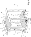
Figure 4 is a schematic perspective view, with some parts cut away to better illustrate others, of another embodiment of the device of the preceding drawings; -
Figure 5 is a schematic side elevation view of the device ofFigure 4 . - With reference to the accompanying drawings, the
numeral 1 denotes in its entirety a device for feeding and accumulating afilm 2 made of plastic material made in accordance with this invention.
Thefilm 2 made of plastic material is wrapped onreels 3 of known type. As illustrated inFigure 1 , thedevice 1 feeds and accumulatesfilm 2 made of plastic material to abagging machine 4.
For example, thebagging machine 4 is used for packaging pieces of pipe made of plastic material, not illustrated, and it is inserted in a production system, at the end of a respective line for feeding these pieces of pipe; the above-mentioned production line and system not being illustrated.
With reference toFigure 1 , thebagging machine 4 comprises anoperational unit 5, partially closed by arespective casing 6.
The pieces of pipe, not illustrated, are fed to theoperating unit 5, by means of afirst conveyor belt 7 and, once packaged in relative bags, also not illustrated, they are discharged by means of asecond conveyor belt 8. As illustrated inFigures 1 to 3 , the feeding and accumulatingdevice 1 comprises aframe 9.
Theframe 9 comprises fourinner uprights 10 the fourouter uprights 11, which are stably connected together by means of a plurality ofcrosspieces 12.
On theinner uprights 10 are positioned, extending longitudinally and parallel to them, respective racks 13.
Thedevice 1 also comprises, not illustrated, means for supportingreels 3 offilm 2.
At its top, thedevice 1 has aunit 14 for drawing thefilm 2 made of plastic material.
Again on the top of thedevice 1, there are, not illustrated, means for splicing the ends of thefilm 2 made of plastic material. - The
unit 14, of substantially known type, comprises tworollers electric motor 15.
Theunit 14 is designed to feed thefilm 2 to thebagging machine 4, unwinding it from therespective reel 3.
Again with reference toFigures 1 to 3 , thedevice 1 comprises tworoller conveyors rollers 18 for redirecting thefilm 2 made of plastic material.
Therollers 18 of eachroller conveyor
Therollers 18 of the above-mentioned upper andlower roller conveyors
Basically, therollers 18 of the above-mentioned first and second group G1, G2 are positioned in two respective rows parallel to each other, thefilm 2 being designed to be wound alternatively on therollers 18 of the two groups G1, G2, forming a coil or a plurality of loops.
As illustrated inFigures 2 and3 , theupper roller conveyor 16 is fixed relative to theframe 9 whilst thelower roller conveyor 17 is movable relative to theframe 9 in a direction vertical to the ground and substantially coincident with the longitudinal extension of theuprights upper roller conveyor 16, thelower roller conveyor 17 remains parallel to itself.
With reference toFigures 1 and2 , thedevice 1 comprises anelectric motor 19 supported by thelower roller conveyor 17 which, by means of suitable motion transmission means 20, is designed to rotate fourgear wheels 21 which each mesh on arespective rack 13.
The above-mentionedracks 13,gear wheels 21,electric motor 19 and motion transmission means 20 together define, for thedevice 1, respective means 22 for relative movement of the first and second group G1, G2 ofrollers 18.
According to a preferred variant embodiment not illustrated, the movement means 22 comprise, in an alternative to the racks and gear wheels, respective lead nut and screw couplings. In this variant, not illustrated, the means 20 for transmitting the motion rotate a plurality of threaded rods which extend parallel to theuprights 10 and engage by screwing in respective threaded holes integral with the lowermovable roller conveyor 17. According to this variant, theelectric motor 19, the transmission means 20 and the threaded rods are supported by theframe 9 and not by themovable roller conveyor 17.
The variation of the distance of the two groups G1, G2, that is to say, of the tworoller conveyors film 2 wound on therollers 18.
Consequently, the variation in the extension of the loops coincides with a variation of the length of thefilm 2 made of plastic material wound between the rollers of the tworoller conveyors
As illustrated in the accompanying drawings, thedevice 1 comprises afirst roller 23 for redirecting thefilm 2 made of plastic material which intercepts, firstly, thefilm 2 arriving towards thelower roller conveyor 17.
The first redirectingroller 23 is supported at its longitudinal ends by twolevers 24.
Thelevers 24 are pivoted on abase 17a (described in more detail below) of thelower roller conveyor 17, so as to oscillate about a respective predetermined axis A parallel to therollers 18.
The above-mentioned first redirectingroller 23 and oscillatinglevers 24 define apendulum device 25.
Thedevice 1 also comprises members 26 for detecting the inclination of the above-mentionedoscillating levers 24.
The detection members 26 comprise acam element 27 fixed to one of thelevers 24, and asensor 28 facing thecam element 27 and operatively connected to it so as to detect the degree of oscillation of thelevers 24 relative to the above-mentioned predetermined axis A. - With specific reference to the embodiment illustrated in
Figures 4 and5 , both the upper andlower roller conveyors base
Each supportingbase
Eachroller conveyor portions 29 for rotatably supporting therespective rollers 18, theportions 29 emerging away from therespective base 29 and from the respective predetermined plane P1, P2.
More specifically, theportions 29 of theupper roller conveyor 16 project downwards whereas theportions 29 of thelower roller conveyor 17 project upwards.
In other words, therollers 18 of eachroller conveyor portions 29, extend completely outside the respective predetermined plane P1, P2.
Thanks to this technical feature just described, together with the fact that therollers 18 of eachroller conveyor rollers 18, the tworoller conveyors roller conveyors film 2 made of plastic material. In other words and with reference toFigures 4 and5 , the interpenetration of theroller conveyors rollers 18 of thelower roller conveyor 17 interposed between the plane P1 and therollers 18 of theupper roller conveyor 16.
By inserting, starting from this configuration, thefilm 2 in the space existing between the two rows ofrollers 18 and moving away the tworoller conveyors film 2 illustrated schematically inFigures 2 and3 is quickly achieved wherein thefilm 2 is wound in the form of a coil around therollers 18 in a succession of loops. - The opportunity just described is particularly useful at the time of activating the
device 1.
The above-mentionedpendulum device 25 and the means 26 for detecting the inclination of the above-mentionedoscillating levers 24 define, in their entirety, means 30 for actuating the movement means 22 which are configured to be controlled as a function of the state of tension of thefilm 2 made of plastic material, as described in more detail below.
In use, during normal operation of the baggingmachine 4, thefilm 2 made of plastic material is fed to it by thedevice 1 by unwinding thefilm 2 from areel 3.
In this mode of normal operation, thedevice 1 is substantially in the configuration illustrated inFigure 2 , that is to say, with the upper andlower roller conveyors
In this configuration, a length L offilm 2 is stored, using the above-mentioned loops, between therollers 18 of the tworoller conveyors device 1.
Thedrawing unit 14 therefore feeds thefilm 2 to themachine 4 unwinding it from thereel 3.
When thereel 3 is close to emptying, thedevice 1, by means sensor devices and signalling units of known type and not described in further detail, notify the operator, with suitable acoustic and/or luminous signals. The operator then locks the end of thefilm 2 being unwound from thereel 3, cuts thefilm 2 at a predetermined position deemed suitable for the joining with the start end of thefilm 2 of a new reel (not illustrated), and splices the two above-mentioned ends of the twofilm 2 together.
At this point, thenew reel 3 is set in the working position and can be normally unwound.
During the operations for joining the two ends of thefilm 2, thedevice 1, using themeans 22 for relative movement, gradually reduces the distance between the tworoller conveyors rollers 18, depending on the request forfilm 2 by the baggingmachine 4, in such a way that the length L offilm 2 stored is used by the baggingmachine 4 without this having to undergo stoppages in its operations due to the changing of thereel 3.
Thependulum device 25 is configured in such a way as to operate as follows.
If thefilm 2 wound around the first redirectingroller 23 is in excess with respect to the needs of the baggingmachine 4, the weight force acting on the first roller 23 (its own or due to masses connected to it) holds thelever 24 inclined downwards, taking thecam element 27 to a distance greater than the maximum reading distance of thesensor 28.
Following this, the detection carried out by thesensor 28 inhibits the dispensing of thefilm 2 to thebagging machine 4. Under normal operation, this is equivalent to keeping inactive thedrawing unit 14 whilst during the steps for changing thereel 3 this is equivalent to keeping inactive themeans 22 for relative movement of theroller conveyors machine 4, the tension of thefilm 2 overcomes the weight force acting on the first redirectingroller 23 and therefore thelever 24 moves horizontally rotating thecam element 27 in such a way that it is detected by thesensor 28.
When thesensor 28 detects thecam element 27, theunit 14 for drawing thefilm 2 is activated, in the case of normal operation, or the movement means 22, during the step of changing thereel 3, so as to bring together theroller conveyors bagging machine 4 the length L offilm 2 stored in thedevice 1.
The invention fulfils the proposed aim and achieves important advantages, guaranteeing an effective procurement of film to the user machine without requiring the stoppage of the machine during operations for changing the reel of film.
Claims (8)
- A device for feeding and accumulating film (2) made of plastic material wound on a reel on a bagging machine (4), comprising:- a frame (9),- a reel (3) of film (2) made of plastic material,- means for supporting at least one reel (3) of film (2) made of plastic material mounted on the frame (9),- a first and a second group (G1, G2) of rollers (18) for redirecting the film (2) made of plastic material, the rollers (18) of the first and second groups (G1, G2) being positioned in two respective rows which are parallel to each other, the film (2) being designed to be wound alternatively on the rollers (18) of the two groups (G1, G2), thus forming a plurality of loops,- means (22) for the relative actuation of the first and second groups (g1, G2), to vary the distance between them and the extension of the loops,- means (30) for activating the actuation means (22), configured to be controlled by the state of tension of the film (2) made of plastic material,characterised in that the activation means (30) comprising a pendulum device (25) having a first roller (23) for redirecting the film (2) made of plastic material, wherein the pendulum device (25) comprises two oscillating levers (24) for supporting the first redirecting roller (23), the levers (24) being designed to oscillate around a predetermined respective axis (A) which is parallel to the rollers (18), and detection members (26) for detecting the inclination of the oscillating levers (24), wherein the detection members (26) comprise a cam element (27) fixed to one of the levers (24), and a sensor (28) facing the cam element (27) and operatively connected to it so as to detect the degree of oscillation of the levers (24) relative to the predetermined axis (A).
- The device according to claim 1, wherein the rollers (18) of the first and second groups (G1, G2) are mounted on two respective roller conveyors (16, 17), characterised in that a first (16) of the roller conveyors is fixed relative to the frame (9) and a second (17) of the roller conveyors is movable relative to the frame (9), and in that the pendulum device (25) is supported by the second movable roller conveyor (17).
- The device according to claim 2, characterised in that the relative actuation means (22) comprise an electric motor (19) supported by the movable roller conveyor (17) in order to put a plurality of gear wheels (21) into rotation, and respective racks (13) fixed to the frame (9) and on which the gearwheels (21) mesh.
- The device according to claim 2, characterised in that the relative actuation means (22) comprise an electric motor (19) supported by the frame (9) and a plurality of lead nut and screw couplings, the motor (19) being designed to put a plurality of threaded rods engaged by screwing with respective threaded holes made integral with the movable roller conveyor (17), into rotation.
- The device according to any of claims 2 to 4, characterised in that the rollers (18) of the first and second roller conveyors (16, 17) are spaced from each other so as to allow at least partial penetration of the roller conveyors (16, 17) themselves to make the insertion of the film (2) made of plastic material possible between the rollers (18) themselves.
- The device according to claim 5, characterised in that at least one of the roller conveyors (16, 17) comprises a supporting base (16a, 17a) which extends substantially in a predetermined plane (P1, P2), and a plurality of portions (29) for rotatably supporting the respective rollers (18), the portions (29) protruding from the plane (P1, P2) so as to allow the penetration of the roller conveyors (16, 17).
- The device according to claim 6, characterised in that the rollers (18) supported by the supporting portions (29) extend completely outside the predetermined plane (P1, P2).
- A system for manufacturing pipes made of plastic material, comprising a line for feeding pieces of pipe made of plastic material, a machine (4) for bagging one or more pieces of pipe, characterised in that it comprises a device (1) for feeding and accumulating film (2) made of plastic material according to any of claims 1 to 7.
Applications Claiming Priority (2)
| Application Number | Priority Date | Filing Date | Title |
|---|---|---|---|
| ITUA2016A002434A ITUA20162434A1 (en) | 2016-04-08 | 2016-04-08 | POWER SUPPLY AND STORAGE OF FILM IN PLASTIC MATERIAL. |
| PCT/IB2017/051891 WO2017175112A1 (en) | 2016-04-08 | 2017-04-03 | Device for feeding and accumulating film made of plastic material |
Publications (2)
| Publication Number | Publication Date |
|---|---|
| EP3439995A1 EP3439995A1 (en) | 2019-02-13 |
| EP3439995B1 true EP3439995B1 (en) | 2020-03-11 |
Family
ID=56507688
Family Applications (1)
| Application Number | Title | Priority Date | Filing Date |
|---|---|---|---|
| EP17718751.5A Active EP3439995B1 (en) | 2016-04-08 | 2017-04-03 | Device for feeding and accumulating film made of plastic material |
Country Status (6)
| Country | Link |
|---|---|
| US (1) | US10994961B2 (en) |
| EP (1) | EP3439995B1 (en) |
| CN (1) | CN108883887B (en) |
| CR (1) | CR20180459A (en) |
| IT (1) | ITUA20162434A1 (en) |
| WO (1) | WO2017175112A1 (en) |
Families Citing this family (4)
| Publication number | Priority date | Publication date | Assignee | Title |
|---|---|---|---|---|
| DE102019119994A1 (en) | 2019-02-20 | 2020-08-20 | Bw Papersystems Stuttgart Gmbh | Device for cutting a web of material into individual sheets with a web memory |
| CN113895737A (en) * | 2021-09-30 | 2022-01-07 | 董研顺 | Large-diameter rubber ring folding machine |
| KR20240082576A (en) * | 2022-12-02 | 2024-06-11 | 주식회사 엘지에너지솔루션 | Pouch film supply device for secondary battery |
| CN117023225A (en) * | 2023-08-25 | 2023-11-10 | 武汉金牛经济发展有限公司 | A store up area device that is used for steel to mould pipe steel area to store up area |
Family Cites Families (11)
| Publication number | Priority date | Publication date | Assignee | Title |
|---|---|---|---|---|
| GB1307524A (en) * | 1969-03-21 | 1973-02-21 | Kodak Ltd | Web or strip material handling apparatus |
| IT1136172B (en) * | 1980-04-09 | 1986-08-27 | Cir Spa Divisione Sasib | ELECTRONIC ADJUSTMENT DEVICE FOR PROGRESSIVE CUTTING IN SHEETS OF A MATERILAE TAPE SPOOL IN SHEET EVEN PRINTED |
| JPS5931244A (en) * | 1982-08-09 | 1984-02-20 | Dainippon Printing Co Ltd | Paper feeder with automatic paper connection |
| AU586574B2 (en) * | 1986-08-15 | 1989-07-13 | William R Warner & Co. Limited | Feeding apparatus |
| DE3727339A1 (en) * | 1987-08-17 | 1989-03-02 | Hans Beck | Device for exchanging film webs wound on a supply roll |
| JPH09328246A (en) * | 1996-06-13 | 1997-12-22 | Shikoku Kakoki Co Ltd | Web accumulator |
| US20050061846A1 (en) * | 2003-08-14 | 2005-03-24 | Martin Automatic, Inc. | Magnetic roller |
| WO2007046137A1 (en) * | 2005-10-19 | 2007-04-26 | Orihiro Engineering Co., Ltd. | Packaging device |
| CN203461581U (en) * | 2013-08-01 | 2014-03-05 | 广东中包机械有限公司 | Embedded numerical control non-stop feeding device for bag making machine |
| CN203833318U (en) * | 2014-05-15 | 2014-09-17 | 浙江强丰革业有限公司 | Cloth storage machine for release paper coating device |
| CN204938485U (en) * | 2015-07-31 | 2016-01-06 | 中山松德新材料装备有限公司 | A kind of storage rack |
-
2016
- 2016-04-08 IT ITUA2016A002434A patent/ITUA20162434A1/en unknown
-
2017
- 2017-04-03 CN CN201780021706.8A patent/CN108883887B/en not_active Expired - Fee Related
- 2017-04-03 CR CR20180459A patent/CR20180459A/en unknown
- 2017-04-03 WO PCT/IB2017/051891 patent/WO2017175112A1/en not_active Ceased
- 2017-04-03 US US16/085,411 patent/US10994961B2/en not_active Expired - Fee Related
- 2017-04-03 EP EP17718751.5A patent/EP3439995B1/en active Active
Non-Patent Citations (1)
| Title |
|---|
| None * |
Also Published As
| Publication number | Publication date |
|---|---|
| CN108883887A (en) | 2018-11-23 |
| CR20180459A (en) | 2019-02-08 |
| WO2017175112A1 (en) | 2017-10-12 |
| CN108883887B (en) | 2020-12-18 |
| ITUA20162434A1 (en) | 2017-10-08 |
| EP3439995A1 (en) | 2019-02-13 |
| US10994961B2 (en) | 2021-05-04 |
| US20190084785A1 (en) | 2019-03-21 |
Similar Documents
| Publication | Publication Date | Title |
|---|---|---|
| US10994961B2 (en) | Device for feeding and accumulating film made of plastic material | |
| RU2744712C2 (en) | Advanced machine and a method of stretch film packaging of products supplied in blocks or separately | |
| CA3109820C (en) | Automatic roll change for stretch wrapping machine | |
| KR100207305B1 (en) | Process for exterior packaging of loads using a stretch film and packaging machine and film spool for carrying out said process | |
| KR19990007926A (en) | Storage device for accumulating semi-manufactured product with means for adjusting forward speed | |
| CN101848839A (en) | Movement and distribution assembly, particularly for products to be packaged | |
| CN108602573B (en) | Method and machine for packaging stretchable film for continuous feed products | |
| JP2019504806A (en) | Packaging method and packaging machine for products supplied in multiple groups with stretchable film | |
| SE470162B (en) | Automatic controlled packaging and goods stacking device | |
| CN111295336A (en) | Packaging machine with turning and stacking device | |
| KR20130019787A (en) | Paper cup automatic packing apparatus | |
| CS216678B2 (en) | Container with variable capacity for objects of the barlike form particularly cigarettes | |
| JP2009214939A (en) | High-speed packaging apparatus and packaging machine having such apparatus | |
| US4924653A (en) | Apparatus for metering a foil web for wrapping objects supplied along a horizontal support | |
| US20190009937A1 (en) | An apparatus and a method for packaging piece goods and in particular containers | |
| EP2978671B1 (en) | A process for the management of a flow of material along a respective plant | |
| JP2022527238A (en) | A system and operating method for wrapping paper rolls. | |
| KR100648573B1 (en) | Gimbap wrapping machine | |
| CH687982A5 (en) | Unit for dispensing of sheet material, for example for the delivery of sheets of cardboard or cartonboard in automatic packaging machines. | |
| EP3019423B1 (en) | Operating accumulation assembly for machines for packaging groups of substantially platelike products and related machine for packaging such groups of products | |
| CN113844925B (en) | Reciprocating winding machine for plastic net cover | |
| WO2004007322A1 (en) | Suplier | |
| US20200391889A1 (en) | Machine and method for packaging piece good combinations with mass balancing element | |
| US20140352258A1 (en) | Festooning device and method for packaging a continuous length of material into a container | |
| IT202100008750A1 (en) | PACKAGING MACHINE WITH DYNAMIC BUFFER AND RELATIVE PREPARATION METHOD |
Legal Events
| Date | Code | Title | Description |
|---|---|---|---|
| STAA | Information on the status of an ep patent application or granted ep patent |
Free format text: STATUS: UNKNOWN |
|
| STAA | Information on the status of an ep patent application or granted ep patent |
Free format text: STATUS: THE INTERNATIONAL PUBLICATION HAS BEEN MADE |
|
| PUAI | Public reference made under article 153(3) epc to a published international application that has entered the european phase |
Free format text: ORIGINAL CODE: 0009012 |
|
| STAA | Information on the status of an ep patent application or granted ep patent |
Free format text: STATUS: REQUEST FOR EXAMINATION WAS MADE |
|
| 17P | Request for examination filed |
Effective date: 20181004 |
|
| AK | Designated contracting states |
Kind code of ref document: A1 Designated state(s): AL AT BE BG CH CY CZ DE DK EE ES FI FR GB GR HR HU IE IS IT LI LT LU LV MC MK MT NL NO PL PT RO RS SE SI SK SM TR |
|
| AX | Request for extension of the european patent |
Extension state: BA ME |
|
| DAV | Request for validation of the european patent (deleted) | ||
| DAX | Request for extension of the european patent (deleted) | ||
| GRAP | Despatch of communication of intention to grant a patent |
Free format text: ORIGINAL CODE: EPIDOSNIGR1 |
|
| STAA | Information on the status of an ep patent application or granted ep patent |
Free format text: STATUS: GRANT OF PATENT IS INTENDED |
|
| INTG | Intention to grant announced |
Effective date: 20191127 |
|
| GRAS | Grant fee paid |
Free format text: ORIGINAL CODE: EPIDOSNIGR3 |
|
| GRAA | (expected) grant |
Free format text: ORIGINAL CODE: 0009210 |
|
| STAA | Information on the status of an ep patent application or granted ep patent |
Free format text: STATUS: THE PATENT HAS BEEN GRANTED |
|
| AK | Designated contracting states |
Kind code of ref document: B1 Designated state(s): AL AT BE BG CH CY CZ DE DK EE ES FI FR GB GR HR HU IE IS IT LI LT LU LV MC MK MT NL NO PL PT RO RS SE SI SK SM TR |
|
| REG | Reference to a national code |
Ref country code: GB Ref legal event code: FG4D |
|
| REG | Reference to a national code |
Ref country code: CH Ref legal event code: EP |
|
| REG | Reference to a national code |
Ref country code: AT Ref legal event code: REF Ref document number: 1242902 Country of ref document: AT Kind code of ref document: T Effective date: 20200315 |
|
| REG | Reference to a national code |
Ref country code: DE Ref legal event code: R096 Ref document number: 602017012972 Country of ref document: DE |
|
| REG | Reference to a national code |
Ref country code: IE Ref legal event code: FG4D |
|
| PG25 | Lapsed in a contracting state [announced via postgrant information from national office to epo] |
Ref country code: NO Free format text: LAPSE BECAUSE OF FAILURE TO SUBMIT A TRANSLATION OF THE DESCRIPTION OR TO PAY THE FEE WITHIN THE PRESCRIBED TIME-LIMIT Effective date: 20200611 Ref country code: FI Free format text: LAPSE BECAUSE OF FAILURE TO SUBMIT A TRANSLATION OF THE DESCRIPTION OR TO PAY THE FEE WITHIN THE PRESCRIBED TIME-LIMIT Effective date: 20200311 Ref country code: RS Free format text: LAPSE BECAUSE OF FAILURE TO SUBMIT A TRANSLATION OF THE DESCRIPTION OR TO PAY THE FEE WITHIN THE PRESCRIBED TIME-LIMIT Effective date: 20200311 |
|
| PGFP | Annual fee paid to national office [announced via postgrant information from national office to epo] |
Ref country code: FR Payment date: 20200429 Year of fee payment: 4 |
|
| REG | Reference to a national code |
Ref country code: NL Ref legal event code: MP Effective date: 20200311 |
|
| PG25 | Lapsed in a contracting state [announced via postgrant information from national office to epo] |
Ref country code: HR Free format text: LAPSE BECAUSE OF FAILURE TO SUBMIT A TRANSLATION OF THE DESCRIPTION OR TO PAY THE FEE WITHIN THE PRESCRIBED TIME-LIMIT Effective date: 20200311 Ref country code: GR Free format text: LAPSE BECAUSE OF FAILURE TO SUBMIT A TRANSLATION OF THE DESCRIPTION OR TO PAY THE FEE WITHIN THE PRESCRIBED TIME-LIMIT Effective date: 20200612 Ref country code: LV Free format text: LAPSE BECAUSE OF FAILURE TO SUBMIT A TRANSLATION OF THE DESCRIPTION OR TO PAY THE FEE WITHIN THE PRESCRIBED TIME-LIMIT Effective date: 20200311 Ref country code: SE Free format text: LAPSE BECAUSE OF FAILURE TO SUBMIT A TRANSLATION OF THE DESCRIPTION OR TO PAY THE FEE WITHIN THE PRESCRIBED TIME-LIMIT Effective date: 20200311 Ref country code: BG Free format text: LAPSE BECAUSE OF FAILURE TO SUBMIT A TRANSLATION OF THE DESCRIPTION OR TO PAY THE FEE WITHIN THE PRESCRIBED TIME-LIMIT Effective date: 20200611 |
|
| REG | Reference to a national code |
Ref country code: LT Ref legal event code: MG4D |
|
| PG25 | Lapsed in a contracting state [announced via postgrant information from national office to epo] |
Ref country code: NL Free format text: LAPSE BECAUSE OF FAILURE TO SUBMIT A TRANSLATION OF THE DESCRIPTION OR TO PAY THE FEE WITHIN THE PRESCRIBED TIME-LIMIT Effective date: 20200311 |
|
| PG25 | Lapsed in a contracting state [announced via postgrant information from national office to epo] |
Ref country code: CZ Free format text: LAPSE BECAUSE OF FAILURE TO SUBMIT A TRANSLATION OF THE DESCRIPTION OR TO PAY THE FEE WITHIN THE PRESCRIBED TIME-LIMIT Effective date: 20200311 Ref country code: PT Free format text: LAPSE BECAUSE OF FAILURE TO SUBMIT A TRANSLATION OF THE DESCRIPTION OR TO PAY THE FEE WITHIN THE PRESCRIBED TIME-LIMIT Effective date: 20200805 Ref country code: SK Free format text: LAPSE BECAUSE OF FAILURE TO SUBMIT A TRANSLATION OF THE DESCRIPTION OR TO PAY THE FEE WITHIN THE PRESCRIBED TIME-LIMIT Effective date: 20200311 Ref country code: IS Free format text: LAPSE BECAUSE OF FAILURE TO SUBMIT A TRANSLATION OF THE DESCRIPTION OR TO PAY THE FEE WITHIN THE PRESCRIBED TIME-LIMIT Effective date: 20200711 Ref country code: LT Free format text: LAPSE BECAUSE OF FAILURE TO SUBMIT A TRANSLATION OF THE DESCRIPTION OR TO PAY THE FEE WITHIN THE PRESCRIBED TIME-LIMIT Effective date: 20200311 Ref country code: EE Free format text: LAPSE BECAUSE OF FAILURE TO SUBMIT A TRANSLATION OF THE DESCRIPTION OR TO PAY THE FEE WITHIN THE PRESCRIBED TIME-LIMIT Effective date: 20200311 Ref country code: SM Free format text: LAPSE BECAUSE OF FAILURE TO SUBMIT A TRANSLATION OF THE DESCRIPTION OR TO PAY THE FEE WITHIN THE PRESCRIBED TIME-LIMIT Effective date: 20200311 Ref country code: RO Free format text: LAPSE BECAUSE OF FAILURE TO SUBMIT A TRANSLATION OF THE DESCRIPTION OR TO PAY THE FEE WITHIN THE PRESCRIBED TIME-LIMIT Effective date: 20200311 |
|
| REG | Reference to a national code |
Ref country code: AT Ref legal event code: MK05 Ref document number: 1242902 Country of ref document: AT Kind code of ref document: T Effective date: 20200311 |
|
| REG | Reference to a national code |
Ref country code: CH Ref legal event code: PL |
|
| REG | Reference to a national code |
Ref country code: DE Ref legal event code: R097 Ref document number: 602017012972 Country of ref document: DE |
|
| PG25 | Lapsed in a contracting state [announced via postgrant information from national office to epo] |
Ref country code: MC Free format text: LAPSE BECAUSE OF FAILURE TO SUBMIT A TRANSLATION OF THE DESCRIPTION OR TO PAY THE FEE WITHIN THE PRESCRIBED TIME-LIMIT Effective date: 20200311 |
|
| PLBE | No opposition filed within time limit |
Free format text: ORIGINAL CODE: 0009261 |
|
| STAA | Information on the status of an ep patent application or granted ep patent |
Free format text: STATUS: NO OPPOSITION FILED WITHIN TIME LIMIT |
|
| PG25 | Lapsed in a contracting state [announced via postgrant information from national office to epo] |
Ref country code: DK Free format text: LAPSE BECAUSE OF FAILURE TO SUBMIT A TRANSLATION OF THE DESCRIPTION OR TO PAY THE FEE WITHIN THE PRESCRIBED TIME-LIMIT Effective date: 20200311 Ref country code: LI Free format text: LAPSE BECAUSE OF NON-PAYMENT OF DUE FEES Effective date: 20200430 Ref country code: AT Free format text: LAPSE BECAUSE OF FAILURE TO SUBMIT A TRANSLATION OF THE DESCRIPTION OR TO PAY THE FEE WITHIN THE PRESCRIBED TIME-LIMIT Effective date: 20200311 Ref country code: ES Free format text: LAPSE BECAUSE OF FAILURE TO SUBMIT A TRANSLATION OF THE DESCRIPTION OR TO PAY THE FEE WITHIN THE PRESCRIBED TIME-LIMIT Effective date: 20200311 Ref country code: LU Free format text: LAPSE BECAUSE OF NON-PAYMENT OF DUE FEES Effective date: 20200403 Ref country code: CH Free format text: LAPSE BECAUSE OF NON-PAYMENT OF DUE FEES Effective date: 20200430 |
|
| REG | Reference to a national code |
Ref country code: BE Ref legal event code: MM Effective date: 20200430 |
|
| 26N | No opposition filed |
Effective date: 20201214 |
|
| PG25 | Lapsed in a contracting state [announced via postgrant information from national office to epo] |
Ref country code: PL Free format text: LAPSE BECAUSE OF FAILURE TO SUBMIT A TRANSLATION OF THE DESCRIPTION OR TO PAY THE FEE WITHIN THE PRESCRIBED TIME-LIMIT Effective date: 20200311 Ref country code: SI Free format text: LAPSE BECAUSE OF FAILURE TO SUBMIT A TRANSLATION OF THE DESCRIPTION OR TO PAY THE FEE WITHIN THE PRESCRIBED TIME-LIMIT Effective date: 20200311 Ref country code: BE Free format text: LAPSE BECAUSE OF NON-PAYMENT OF DUE FEES Effective date: 20200430 |
|
| GBPC | Gb: european patent ceased through non-payment of renewal fee |
Effective date: 20210403 |
|
| PG25 | Lapsed in a contracting state [announced via postgrant information from national office to epo] |
Ref country code: FR Free format text: LAPSE BECAUSE OF NON-PAYMENT OF DUE FEES Effective date: 20210430 Ref country code: GB Free format text: LAPSE BECAUSE OF NON-PAYMENT OF DUE FEES Effective date: 20210403 |
|
| PG25 | Lapsed in a contracting state [announced via postgrant information from national office to epo] |
Ref country code: MT Free format text: LAPSE BECAUSE OF FAILURE TO SUBMIT A TRANSLATION OF THE DESCRIPTION OR TO PAY THE FEE WITHIN THE PRESCRIBED TIME-LIMIT Effective date: 20200311 Ref country code: CY Free format text: LAPSE BECAUSE OF FAILURE TO SUBMIT A TRANSLATION OF THE DESCRIPTION OR TO PAY THE FEE WITHIN THE PRESCRIBED TIME-LIMIT Effective date: 20200311 |
|
| PG25 | Lapsed in a contracting state [announced via postgrant information from national office to epo] |
Ref country code: MK Free format text: LAPSE BECAUSE OF FAILURE TO SUBMIT A TRANSLATION OF THE DESCRIPTION OR TO PAY THE FEE WITHIN THE PRESCRIBED TIME-LIMIT Effective date: 20200311 Ref country code: AL Free format text: LAPSE BECAUSE OF FAILURE TO SUBMIT A TRANSLATION OF THE DESCRIPTION OR TO PAY THE FEE WITHIN THE PRESCRIBED TIME-LIMIT Effective date: 20200311 |
|
| P01 | Opt-out of the competence of the unified patent court (upc) registered |
Effective date: 20230517 |
|
| PGFP | Annual fee paid to national office [announced via postgrant information from national office to epo] |
Ref country code: TR Payment date: 20240320 Year of fee payment: 8 |
|
| PGFP | Annual fee paid to national office [announced via postgrant information from national office to epo] |
Ref country code: IE Payment date: 20240417 Year of fee payment: 8 |
|
| PGFP | Annual fee paid to national office [announced via postgrant information from national office to epo] |
Ref country code: DE Payment date: 20240429 Year of fee payment: 8 |
|
| PGFP | Annual fee paid to national office [announced via postgrant information from national office to epo] |
Ref country code: IT Payment date: 20250428 Year of fee payment: 9 |
|
| REG | Reference to a national code |
Ref country code: DE Ref legal event code: R119 Ref document number: 602017012972 Country of ref document: DE |
|
| PG25 | Lapsed in a contracting state [announced via postgrant information from national office to epo] |
Ref country code: DE Free format text: LAPSE BECAUSE OF NON-PAYMENT OF DUE FEES Effective date: 20251104 |
|
| PG25 | Lapsed in a contracting state [announced via postgrant information from national office to epo] |
Ref country code: IE Free format text: LAPSE BECAUSE OF NON-PAYMENT OF DUE FEES Effective date: 20250403 |