EP3439949B1 - A control system for an engine with safety control - Google Patents
A control system for an engine with safety control Download PDFInfo
- Publication number
- EP3439949B1 EP3439949B1 EP16721848.6A EP16721848A EP3439949B1 EP 3439949 B1 EP3439949 B1 EP 3439949B1 EP 16721848 A EP16721848 A EP 16721848A EP 3439949 B1 EP3439949 B1 EP 3439949B1
- Authority
- EP
- European Patent Office
- Prior art keywords
- key
- engine control
- user
- hmi
- function
- Prior art date
- Legal status (The legal status is an assumption and is not a legal conclusion. Google has not performed a legal analysis and makes no representation as to the accuracy of the status listed.)
- Active
Links
Images

Classifications
-
- F—MECHANICAL ENGINEERING; LIGHTING; HEATING; WEAPONS; BLASTING
- F02—COMBUSTION ENGINES; HOT-GAS OR COMBUSTION-PRODUCT ENGINE PLANTS
- F02D—CONTROLLING COMBUSTION ENGINES
- F02D11/00—Arrangements for, or adaptations to, non-automatic engine control initiation means, e.g. operator initiated
- F02D11/06—Arrangements for, or adaptations to, non-automatic engine control initiation means, e.g. operator initiated characterised by non-mechanical control linkages, e.g. fluid control linkages or by control linkages with power drive or assistance
- F02D11/10—Arrangements for, or adaptations to, non-automatic engine control initiation means, e.g. operator initiated characterised by non-mechanical control linkages, e.g. fluid control linkages or by control linkages with power drive or assistance of the electric type
- F02D11/107—Safety-related aspects
-
- B—PERFORMING OPERATIONS; TRANSPORTING
- B63—SHIPS OR OTHER WATERBORNE VESSELS; RELATED EQUIPMENT
- B63H—MARINE PROPULSION OR STEERING
- B63H21/00—Use of propulsion power plant or units on vessels
- B63H21/22—Use of propulsion power plant or units on vessels the propulsion power units being controlled from exterior of engine room, e.g. from navigation bridge; Arrangements of order telegraphs
Definitions
- the present invention relates to a control system for an engine such as a diesel engine, a gas engine or a liquid natural gas (LNG) engine, where the control system is equipped with a safety control means that may be employed e.g. to ensure safety of the maintenance personnel during maintenance operations applied to the engine.
- a safety control means that may be employed e.g. to ensure safety of the maintenance personnel during maintenance operations applied to the engine.
- Engines of several types such as internal combustion engines (ICE) like diesel engines, gas engines and LNG engines, are commonly used for various industrial purposes to supply power e.g. in power plants, in marine vessels, in offshore platforms such as oil rigs, etc.
- ICE internal combustion engines
- LNG engines LNG engines
- a single engine or an engine system of a plurality (e.g. two or more) engines may be employed as the power source.
- a high operational reliability and early reaction to any need for maintenance of an engine is typically a critical characteristic for the performance of the engine or engine system, while any maintenance operation to be carried out for an engine preferably requires as short downtime of the engine as possible to limit the interruptions or reductions in the power supply from the engine or engine system.
- a maintenance operation performed on a large engine typically employed in such usage scenarios requires special attention to the safety of the maintenance personnel.
- there is typically a need to ensure that the engine is not accidentally started during a maintenance operation for safety reasons which in known solutions is typically provided via a mechanical or electro-mechanical switch provided for the purpose of switching off the power from the engine.
- this may lead to a cumbersome and/or unsatisfactory solution that may result in prolonged or sometimes even unnecessary downtime of the engine in view of the characteristics of the maintenance operation in question.
- US 2007/227429 A1 discloses an outboard motor control system that can have a first PTT switch and a second PTT switch in a first steering station and in a second steering station respectively, and a third PTT switch in a location outside of a boat hull.
- Operation instruction given by each PTT switch can be input to a first microcomputer of a first ECU.
- the first microcomputer can determine if the inputted operation instruction is to be sent to the outboard motor, based on which PTT switch the operation instruction came from, whether the main switch is ON or OFF, and which steering station has precedence in boat control.
- US 2005/181685 A1 discloses a main switch apparatus of a small watercraft.
- the main switch apparatus of a small watercraft having a main switch.
- the main switch apparatus includes a plurality of keys, each for operating the main switch, each assigned a different user ID information.
- the main switch apparatus may further include an ID information detector for detecting the user ID information assigned to one of the plurality of keys applied to the main switch, a controller for controlling the small watercraft, configured to be activated by each one of the plurality of keys, and a control pattern memory for storing a plurality of control patterns of the controller corresponding to the respective user ID information.
- the controller is typically configured to read out the control pattern stored in the control pattern memory corresponding to the user ID information detected by the user ID information detector and to execute a control of the watercraft based on the read out control pattern
- an engine control system for controlling user access to one or more engine control functions, where the engine control system is communicatively coupled to an engine via an engine control interface and where the engine control system comprises two or more human-machine interface, HMI, units, each HMI unit comprising a respective user interface, UI, for providing user access to respective one or more engine control functions, wherein at least two HMI units comprise a respective lock means for receiving a safety key that represents a key identification, ID, of a plurality of key IDs, wherein each key ID has respective at least one engine control function associated therewith, wherein the engine control system is arranged to, when the lock means in a first HMI unit is in receipt of the safety key that represents a first key ID of said plurality of key IDs, selectively enable via the UI of said first HMI unit one of the following: a user-operable locking function for locking, by the first key ID, said respective at least one engine control function associated with the first key ID to disable user access, via said Uls, to said respective
- an engine control arrangement comprising one or more engine control systems according to the example embodiment described in the foregoing and a local central control unit, LCCU, communicatively coupled to said one or more engine control systems, wherein the LCCU comprises a UI for providing user access to one or more engine control functions in said one or more engine control systems and further comprises at least one lock means for receiving a safety key that represents a key ID of said plurality of key IDs, which key ID has respective at least one engine control function associated therewith, and wherein the engine control arrangement is configured to, when the lock means in the LCCU is in receipt of the safety key that represents said first key ID, selectively enable via the UI of the LCCU one of the following: a user-operable locking function for locking, by the first key ID, the respective at least one engine control function associated with the first key ID to disable user access, via all UIs in the engine control arrangement, to said respective at least one engine control function or a user-operable unlocking function for
- a method for controlling user access to one or more engine control functions in an engine control system that is communicatively coupled to an engine via an engine control interface comprising operating two or more HMI units, each HMI unit comprising a respective UI for providing user access to respective one or more engine control functions, wherein at least two HMI units comprise a respective lock means for receiving a safety key that represents a key ID of a plurality of key ID, wherein each key ID has respective at least one engine control function associated therewith, and selectively enabling, via the UI of a first HMI unit, when the lock means in the first HMI unit is in receipt of the safety key that represents a first key ID of said plurality of key IDs, one of the following: a user-operable locking function for locking, by the first key ID, said respective at least one engine control function associated with the first key ID to disable user access, via said Uls, to said respective at least one engine control function or a user-operable unlocking function for releasing said respective at least one
- a computer program comprising computer readable program code configured to cause performing at least the method according to the example embodiment described in the foregoing when said program code is executed on one or more computing apparatuses.
- the computer program referred to above may be embodied on a volatile or a non-volatile computer-readable record medium, for example as a computer program product comprising at least one computer readable non-transitory medium having program code stored thereon, the program which when executed by an apparatus cause the apparatus at least to perform the operations described hereinbefore for the computer program according to an example embodiment of the invention.
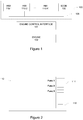
- FIG. 1 illustrates a block diagram of some components of an engine control system 100 according to an example.
- the engine control system 100 is illustrated with local human-machine interface (HMI) units 110-1, 110-2, ..., 110-K.
- HMI unit 110-k comprises a user interface (UI) that provides user access to one or more engine control functions for controlling operation of an engine 102.
- UI user interface
- ECI engine control interface
- the ECI 101 is coupled to an engine 102 and it serves to convert the engine control information received from the HMI units 110 to respective control actions for controlling the engine 102 (e.g. by using respective drivers or actuators provided as part of the ECI 101) and to convert the engine status information (obtained e.g. by using respective sensors provided as part of the ECI 101) in format suitable for provision to the HMI units 110.
- the ECI 101 may be provided by hardware or as a combination of hardware and software.
- the engine 102 may be, for example, an internal combustion engine such as a diesel engine, a gas engine or a LNG engine, and the engine 102 may be a stand-alone engine or the engine 102 may operate as part of an engine system of a plurality (e.g. two or more) engines.
- the details of operation of the ECI 101 and/or the engine 102 are not directly relevant to embodiments of the present invention but they are outlined here to illustrate the relationship between the engine 102 and the engine control system 100.
- the HMI units 110-1, 110-2, ..., 110-k illustrated in Figure 1 represent one or more HMI units 110 and for a given engine the number of HMI units 110 may be one, two, three, etc., depending on the physical size of the engine 102 in view of the desired 'ease' of accessing the HMI units 110 by the persons operating the engine 102.
- an engine that is small in size may require only single HMI unit 110, whereas an engine that is large in size likely benefits from a plurality of HMI units 110 to enable timely and convenient access to the control functions enabled by the HMI units 110 at multiple locations.
- the engine control system 100 further comprises a safety control database (SCDB) 120, which may be provided in a data storage means that is communicatively coupled to the HMI units 110.
- the data storage means applied for storing the SCDB 120 may be provided e.g. as a dedicated data storage entity (as depicted in the example of Figure 1 ), as part of the ECI 101 or as part of one of the HMI units. Due to the communicative coupling, each of the HMI units 110-k is able to read data from the SCDB 120 and write data to the SCDB 120.
- the information content and purpose of the SCDB 120 is described later in this text.
- a bus 105 which may comprise e.g. a controller area network (CAN) bus or another suitable bus known in the art.
- CAN controller area network
- the bus 105 may be provided as one or more separate buses.
- a HMI unit 110-k may be integrated to a component or part of the engine 102, e.g. by arranging the HMI unit 110-k in a housing of the engine 102. As another example, the HMI unit 110-k may be arranged in close proximity to the engine 102, e.g. in a respective 'control desk' arranged in immediate proximity to the engine 102, in an engine room or in an engine control room.
- the HMI unit 110 comprises a UI that provides access to one or more user functions that enable a user to control a respective aspect of the engine operation.
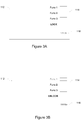
- Figure 2 schematically illustrates the UI aspect of the HMI unit 110 according to an example.
- the HMI unit 110 comprises display means 112 for displaying visual information to a user.
- the display means may be provided as an electronic display, such as a light-emitting diode (LED) display, an organic light-emitting diode (OLED) display, an electroluminescent display (ELD), a liquid crystal display (LCD), etc.
- the HMI unit 110 further comprises a user input means 114 for receiving input from the user.
- the user input means 114 includes an arrangement of programmable push-buttons, which may referred to as softkeys.
- the function invoked by operating a given softkey may be described by a text or by a visual identifier in a portion of the display means 112 adjacent to the given softkey, whereas the remaining part of the display 112 may be employed e.g. for displaying information that is indicative of the current status one or more aspects of the engine operation.
- the user input means may comprise elements or components of other type, e.g. one or more of the following: one or more further arrangements of keys or buttons (in another location(s)) of the UI, a keyboard, a mouse or a pointing device of other type, a touchpad, etc.
- the display means 112 is provided as a touchscreen, thereby providing at least part of the user input means 114 as a component integrated to the display means 112.
- the engine control functions accessible by the user via the softkeys of the user input means 114 are described in a generic manner as "Func 1", “Func 2" and “Func 3" and they serve to represent any suitable respective engine control functions.
- the engine functions that are controllable via the UI provided in the HMI unit 110-k typically include at least an engine control function for starting the engine 102 and an engine control function for stopping the engine 102.
- the UI may provide a number of additional control functions for adjusting a certain operating characteristic of the engine 102 and/or for selecting information indicative of a certain operating characteristic of the engine 102 to be displayed via the display means 112.
- control functions for adjusting an operating characteristic of the engine 102 or for selecting information indicative of a certain operating characteristic of the engine 102 to be displayed may comprise one or more of the following:
- the engine control functions available via user functions provided in the respective UIs of the HMI units 110 may vary from one HMI unit 110 to another.
- a first set of engine control functions that are accessible via the UI in a first HMI unit 110-k need not be the same as a second set of engine control functions that are accessible via a second HMI unit 110-j (where k ⁇ j).
- the engine control functions available in different HMI units 110 e.g. the first and second sets of engine control functions, share one or more engine control functions, e.g. the engine control function for starting the engine 102 and/or the engine control function for stopping the engine 102.
- At least one of the HMI units of the engine control system 100 further comprises a lock means 116 for receiving a safety key.
- the HMI unit 110-k is configured to selectively provide via its UI a locking function or unlocking function for controlling availability of one or more engine control functions (otherwise) provided via respective UIs of one or more HMI units 110 of the engine control system 100 when the lock means 116 is in receipt of the safety key.
- a safety key represents a predefined key identifier (ID) assigned therefor, which key ID serves as a unique identification of the particular safety key.
- ID key identifier
- Each key ID, and hence each safety key is associated with one or more engine control functions that are (normally) available via respective UI of at least one HMI unit 110 of the engine control system 100.
- the information that defines the mapping between a key ID and the associated engine control function may be stored in the SCDB 120.
- the SCDB 120 may include a key information table that comprises a respective table entry for each key ID configured for use in the engine control system 100.
- each table entry includes the respective key ID, identifications of one or more associated engine control functions associated with the key ID (i.e. one or more engine control functions whose availability via the HMI units 110 is controllable by the key ID) of the same table entry, and an indication whether the respective key ID is currently applied to lock the associated engine control function(s).
- Table 1 in the following provides an illustrative example of a content of a key information table.
- three key IDs (#1, #2 and #3) are considered, where the key IDs #1 and #2 are associated with the engine control functions "Func 1" and “Func 2", whereas the key ID #3 is associated with the engine control functions "Func 1", “Func 2" and “Func 3".
- the example of Table 1 further indicates the key ID #2 is currently being applied to lock the engine control functions associated therewith (i.e. the engine control function "Func 1"), whereas there is no indication of other key IDs being currently applied to lock the respective associated engine control functions.
- Table 1 Key ID Associated engine control functions Active? #1 "Func 1" #2 "Func 1" YES #3 "Func 1", "Func 2, "Func 3"
- the SCDB 120 may additionally include information that defines for each engine control function that is accessible via at least one of the HMI units 110 of the engine control system 100 and whose availability is controllable through at least one key ID whether it is currently available (and/or currently non-available).
- the SCDB 120 may additionally include a control function status table that comprises a respective table entry for each engine control function whose availability is controllable though at least one key ID configured for use in the engine control system 100.
- each table entry includes an identification of the respective engine control function and an indication whether any key IDs are currently applied to lock this engine control function.
- the latter piece of information may be provided as a list of zero or more key IDs that identify those safety keys that are currently applied to lock this engine control function or as an indication of the number of key IDs that are currently applied to lock this engine control function.
- Table 2 in the following provides an illustrative example of a content of a control function status table.
- three engine control functions (“Func 1", “Func 2" and “Func 3" are considered.
- the control function "Func 1" is indicated as currently locked via usage of the key ID #1
- the control function "Func 2" is indicated currently locked via usage of the key IDs #1 and #3 (the Table 2 hence exemplifying the approach where the indication whether any key IDs are currently applied to lock this engine control function is provided by listing the associated key IDs), while no key IDs are currently applied to lock the engine control function "Func 3".
- Table 2 Control function Currently locked by "Func 1" #1 "Func 2" #1 #3 "Func 3"
- a key ID read from a safety key received by the lock means 116 in a HMI unit 110-k is the key ID(k).
- the key ID(k) is obtained (e.g. read) from the safety key and the SCDB 120 is accessed to determine whether the key ID(k) is currently being applied to lock the one or more engine control functions associated therewith. This determination may be carried out e.g. by identifying the table entry of the key information table in the SCDB 120 that corresponds to the key ID(k) and determining whether the identified table entry indicates locking of the associated control function(s).
- the UI of the HMI unit 110-k is updated to enable the locking function that serves to disable the engine control functions associated with the key ID(k).
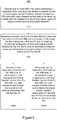
- An illustrative example in this regard is provided in Figure 3A , where the lowermost softkey of the user input means 114 (identified by the text "LOCK" in a portion of the display means 112 adjacent thereto) enables locking of the associated engine control functions by using the key ID(k).
- the UI of the HMI unit 110-k is updated to enable the unlocking function that serves to release (unlock) the engine control functions associated with the key ID(k) from being locked by using the key ID(k).
- An illustrative example in this regard is provided in Figure 3B , where the lowermost softkey of the user input means 114 (identified by the text "UNLOCK" in a portion of the display means 112 adjacent thereto) enables unlocking of the associated engine control functions.
- FIG. 3B further shows the engine control function "Func 1" associated with the key ID(k) being disabled (indicated by the de-emphasized associated text "Func 1" in a portion of the display means 112 adjacent to the uppermost softkey of the user input means 114) due to locking (at least) by the key ID(k).
- the locking function or the unlocking function for controlling availability of one or more engine control functions associated with the key ID(k) is available only when the lock means 116 in the HMI unit 110-k is in receipt of the safety key that represents the key ID(k).
- the UI of the HMI unit 110-k is updated such that the locking function or the unlocking function is no longer available via the UI.
- the locking function or the unlocking function for controlling availability of one or more engine control functions associated with the key ID(k) is available only via the UI of the HMI unit 110-k in which the lock means 116 is in receipt of the safety key representing the key ID(k). This ensures that only the person accessing the engine control functions via the UI in the HMI unit 110-k has the control for locking or unlocking the associated engine control functions, thereby facilitating prevention of unauthorized persons from disabling or re-enabling the associated engine control functions.
- the user may use his/her safety key to (first) enable and engage the locking function to lock the engine control functions associated with the key ID represented by his/her safety key via the UI of the HMI unit 110-k, carry out desired maintenance operations on the engine 102, and (subsequently) enable and engage the unlocking function to release the respective associated engine control functions via the UI of the same HMI unit 110-k.
- the user uses his/her safety key to (first) enable and engage the locking function to lock the associated engine control functions via the UI of the HMI unit 110-k, carry out desired maintenance operations on the engine 102, and (subsequently) enable and engage the unlocking function to release the respective associated engine control functions via the UI of another HMI unit 110-j (where j ⁇ k).
- locking of the associated engine control functions may further require, in addition to the user engaging the locking function via the UI of the HMI-unit 110-k, receiving a valid personal identification code via the UI of the HMI-unit 110-k.
- releasing (unlocking) of the associated engine control functions may further require, in addition to the user engaging the unlocking function via the UI of the HMI-unit 110-k, receiving the valid personal identification code via the UI of the HMI-unit 110-k.
- the user engaging the locking or unlocking function may be followed by the HMI unit 110-k requesting, via the UI, the user to enter the personal identification code, such as a password or a PIN code, assigned to the key ID(k) before the HMI unit 110-k proceeds with implementing the locking or release of the associated engine control functions.
- the user may apply e.g. a keyboard provided in the HMI unit 110-k or a touchscreen of the HMI unit 110-k to enter the personal identification code.
- the code entered by the user is compared to the personal identification code assigned to the key ID(k) and the HMI unit 110-k may proceed with implementing the locking or release of the associated engine control functions in response to the user-entered code matching the personal identification code assigned to the key ID(k).
- Usage of the personal identification code serves as an additional safety measure that facilitates prevention of unauthorized persons from locking or releasing the associated engine control functions.
- the lock means 116 and the safety key(s) are provided using universal serial bus (USB) technology known in the art.
- USB universal serial bus
- the lock means 116 may be provided as an USB port and one or more safety keys may be provided as respective USB devices, e.g. as respective US memory sticks, each arranged to store information that serves as an indication of the respective key ID assigned thereto in a predefined format.
- the lock means 116 is in receipt of a safety key when the USB device is connected to the USB port such that HMI unit 110-k is able to read the key ID therefrom.
- the lock means 116 and the safety key(s) are provided by employing a radio frequency identification (RFID) technique known in the art.
- RFID radio frequency identification
- the lock means 116 may be provided as an RFID reader and one or more safety keys may be provided as respective RFID tags, each arranged to store information that serves an indication of the respective key ID assigned thereto.
- the lock means 116 is in receipt of a safety key when the RFID reader is able to read the key ID from the ID tag.
- the lock means 116 and the safety key(s) are provided by employing a near field communication (NFC) technique known in the art.
- NFC near field communication
- the lock means 116 may be provided as a first NFC device and one or more safety keys may be provided as respective second NFC devices, each arranged to store information that serves an indication of the respective key ID assigned thereto.
- the lock means 116 is in receipt of a safety key when the first NFC device is able to read the key ID from the second NFC device.
- the lock means 116 and the safety key(s) are provided by employing a fingerprint recognition technique known in the art.
- the lock means 116 may be comprise a fingerprint sensor and a safety key for a certain user comprises a finger of the certain user.
- the lock means 116 may store one or more predefined fingerprint templates, each fingerprint template associated with a respective key ID.
- the lock means 116 further compares a fingerprint obtained via the fingerprint sensor to the stored one or more predefined fingerprint templates and obtains the key ID as the key ID associated with the predefined fingerprint template recognized to match (e.g. to be similar or substantially similar to) the fingerprint obtained via the fingerprint sensor.
- the lock means 116 and the safety key(s) are provided by employing a facial recognition system or technique known in the art.
- the lock means 116 may comprise imaging means (such as a digital camera) and a safety key for a certain user comprises the face of the certain user (or part thereof).
- the lock means 116 may store one or more sets of predefined facial features, each set associated with a respective key ID.
- the lock means 116 further compares facial features extracted from an image of a face obtained from the imaging means to the stored one or more sets of predefined facial features and obtains the key ID as the key ID associated with the set of predefined facial features found to match (e.g. to be similar or substantially similar to) the facial features extracted from the image of a face obtained from the imaging means.
- the lock means 116 and the safety key(s) are provided by employing an iris recognition system or technique known in the art.
- the lock means 116 may comprise imaging means (such as a digital camera) and a safety key for a certain user comprises an iris of the certain user (or part thereof).
- the lock means 116 may store one or more predefined iris templates, each associated with a respective key ID.
- the lock means 116 further compares an image of an iris obtained from the imaging means to the stored one or more iris templates and obtains the key ID as the key ID associated with the predefined iris template found to match (e.g. to be similar or substantially similar to) the image of an iris obtained from the imaging means.
- FIG. 4 illustrates a block diagram of some components of an engine control system 200 according to an example, which is a variation of the engine control system 100, operation of which is described in the foregoing by a number of examples.
- the engine control system 200 further comprises a local central control unit (LCCU) 130 that is communicatively coupled to the SCDB 120 and to the ECI 101, and possibly also to the HMI units 110.
- LCCU local central control unit
- the LCCU 130 comprises a UI that provides one or more engine control functions for controlling operation of an engine 102.
- the UI of the LCCU 130 provides an enlarged selection of engine control functions in comparison to the respective Uls of the HMI units 110.
- the UI of the LCCU 130 may provide all those engine control functions that are available via the respective Uls of any of the HMI units 110 of the engine control system 200 and it may provide one or more further engine control functions that are not available via the respective Uls of any of the HMI units 110 of the engine control system 200.
- the LCCU 130 is, typically, provided in a control center or in a control room that is located in the site of the engine 102, e.g. in or close to an engine room of a marine vessel (at least in part) powered by the engine 102 or in or close to engines of an engine-powered power plant that is (at least in part) powered by the engine 102.
- the control center/room that hosts the LCCU 130 is typically provided somewhat further away from the engine 102 (and possible other engines of the site) than any of the HMI units 110 of the engine control system 200.
- the LCCU 130 Due to the communicative coupling, the LCCU 130 is able to read data from the SCDB 120 and write data to the SCDB 120. Therefore, in case the any of the HMI units 110 have been applied to engage the locking function to lock some of the engine control functions available in the engine control system 200, the LCCU 130 may access the SCDB 120 (e.g. the key information table and/or the control function status table therein) to obtain an indication in this regard and disable access to the associated engine control functions via the UI of the LCCU 130 accordingly.
- the SCDB 120 e.g. the key information table and/or the control function status table therein
- the LCCU 130 may access the SCDB 120 (e.g. the key information table and/or the control function status table therein) to obtain an indication in this regard and re-enable access to the associated engine control functions via the UI of the LCCU 130 accordingly.
- SCDB 120 e.g. the key information table and/or the control function status table therein
- the LCCU 130 may comprise a lock means 136 for receiving the safety key.
- the operation of the LCCU 130 when in receipt of the safety key is similar to that described in the foregoing in context of the HMI unit 110-k, mutatis mutandis.
- a safety key may be applied in the LCCU 130 to enable, via the UI of the LCCU 130, locking or releasing (unlocking) the associated engine control functions in the HMI units 110 (as well as via the UI of the LCCU 130) of the engine control system 200.
- FIG. 5 illustrates a block diagram of some components of an engine control arrangement that comprises the engine control system 100 and the LCCU 130.
- the LCCU 130 connects to the engine control system 100 via the bus 105.
- the LCCU 130 is provided outside the engine control system 100 and it is connected to one or more further engine control systems 100' (represented in the Figure 5 by two instances denoted by the reference designator 100').
- Each of the engine control systems 100' is arranged to control operation of the respective engine via a respective ECI (e.g. along the lines described in the foregoing for the engine control system 100).
- the LCCU 130 serves to provide control over a plurality of (e.g. two or more) engines via the respective engine control systems 100, 100'.
- the LCCU 130 is provided with a single lock means via which control over availability of the engine control functions in each of the engine control systems 100, 100' coupled thereto may be provided by using a single safety key (e.g. by reading/writing the respective SCDBs 120 of the engine control systems 100, 100' and controlling availability of the engine control functions via respective Uls of the HMI units 110 in the engine control systems 100, 100' (and via the UI of the LCCU 130) accordingly, e.g. as described in the foregoing in context of the HMI units 110 of the engine control system 100).
- the UI of the LCCU 130 may enable the user selecting the engine control systems 100, 100' to be affected in response to receiving the safety key in the lock means.
- the LCCU 130 in the engine control arrangement of Figure 5 ) may be provided with a dedicated lock means for each of the engine control systems 100, 100' coupled to the LCCU 130.
- a single safety key is useable to control availability of the engine control functions in single one of the engine control systems 100, 100' coupled to the LCCU 130 at a time, in the engine control system 100, 100' that is associated with the lock means that is currently in receipt of the safety key.
- Figure 6 depicts a flowchart that outlines a method 300 according to an example embodiment.
- the method 300 may implement some aspects of the engine control system 100 described in the foregoing by a number of examples.
- the method 300 may be carried out by one or more computing devices that are arranged to implement at least the one or more HMI units 110 and the SCDB 120.
- the method 300 serves to control user access to one or more engine control functions in the engine control system 100 that is communicatively coupled to the engine 102 via the ECI 101.
- the method 300 comprises operating the one or more HMI units 110, each HMI unit 110 comprising a respective UI for providing user access to respective one or more engine control functions, wherein at least one HMI unit 110 comprises the respective lock means 116 for receiving a safety key storing a key ID, which key ID has at least one engine control function associated therewith, as indicated in block 310.
- the method further comprises selectively providing, via the UI of a first HMI unit, when the lock means 116 in the first HMI unit is in receipt of the safety key storing a first key ID one of the following: a locking function for locking said at least one engine control function by the first key ID and an unlocking function for releasing said at least one engine control function from locking by the first key ID, as indicated in block 320.
- the method 300 may further comprise one or more of operations described in blocks 330A and 330B: disable, via the respective UI of each of the HMI units 100, in response to a user engaging the locking function via the UI of the first HMI unit, user access to said at least one engine control function associated with the first key ID (block 330A) and/or re-enable, via the respective UI of each of the HMI units 100, in response to a user engaging the unlocking function via the UI of the first HMI unit, user access to those ones of said at least one engine control function associated with the first key ID that are not locked by one or more other key IDs (block 330B).
- the method 300 outlined herein may be varied in a number of ways, e.g. as described in context of the engine control system 100, 100' or the engine control arrangement described with references to Figure 5 .
- Components of the engine control system 100, 100' may be provided by using respective hardware means, respective software means, or respective combination of hardware means and software means.
- each of the HMI units 110, the SCDB 120 and the LCCU 130 may be provided respective hardware means, respective software means, or respective combination of hardware means and software means.
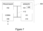
- FIG. 7 schematically illustrates some components of an exemplifying apparatus 400 suited for this purpose.
- the apparatus 400 comprises a processor 402 and a memory 404 for storing data and computer program code 406.
- the memory 404 may store information that constitutes the SCDB 120.
- the processor 402 is configured to read from and write to the memory 404.
- the apparatus 400 further comprises a communication means 408 for communicating with another apparatuses or devices, e.g. with other components of the engine control system 100, 100'.
- the apparatus 400 further comprise user I/O (input/output) components 410 that may be arranged, together with the processor 402 and a portion of the computer program code 406, to provide a user interface for receiving input from a user and/or providing output to the user.
- the user I/O components 410 may comprise hardware components such as a display, a touchscreen, a touchpad, a mouse, a keyboard and/or an arrangement of one or more keys or buttons, etc.
- at least some of the user I/O components 410 may serve to provide the display means 112 and the user input means 114 of a HMI unit 110 described in the foregoing.
- the processor 402 may be arranged to control operation of the apparatus 400 in accordance with a portion of the computer program code 406 stored in the memory 404 and possibly further in accordance with the user input received via the user I/O components 410 and/or in accordance with information received via the communication means 408.
- the memory 404 and a portion of the computer program code 406 stored therein may be further arranged, with the processor 402, to provide a control function or control means for controlling operation of the apparatus 400.
- the processor 402, the memory 404, the communication means 408 and the user I/O components 410 may be interconnected by a bus 412 that enables transfer of data and control information.
- the apparatus 400 may comprise further components in addition to those shown in the illustration of Figure 7 .
- processor 402 is depicted as a single component, the processor 402 may be implemented as one or more separate processing components.
- the memory 402 is depicted as a single component, the memory 404may be implemented as one or more separate components, some or all of which may be integrated/removable and/or may provide permanent / semi-permanent/ dynamic/cached storage.
- the computer program code 406 stored in the memory 404 may comprise computer-executable instructions that control the operation of the apparatus 400 when loaded into the processor 402.
- the computer program code 406 may include one or more sequences of one or more instructions.
- the processor 402 is able to load and execute the computer program code 406 by reading the one or more sequences of one or more instructions included therein from the memory 404.
- the one or more sequences of one or more instructions may be configured to, when executed by the processor 402, cause the apparatus 400 to carry out operations, procedures and/or functions described in the foregoing in context of the respective component of the engine control system 100, 100', e.g. those described for the HMI unit 110, the SCDB 120 or the LCCU 130.
- the computer program code 406 may be provided e.g. as a computer program product comprising at least one computer-readable non-transitory medium having program code stored thereon, the computer program code 406, when executed by the apparatus 400, arranged to cause the apparatus 400 to carry out operations, procedures and/or functions described in the foregoing in context of the respective component of the engine control system 100, 100', e.g. those described for the HMI unit 110, the SCDB 120 or the LCCU 130.
- the computer-readable non-transitory medium may comprise a memory device or a record medium such as a CD-ROM, a DVD, a Blu-ray disc or another article of manufacture that tangibly embodies the computer program.
- the computer program may be provided as a signal configured to reliably transfer the computer program.
- references(s) to a processor should not be understood to encompass only programmable processors, but also dedicated circuits such as field-programmable gate arrays (FPGA), application specific circuits (ASIC), signal processors, etc.
- FPGA field-programmable gate arrays
- ASIC application specific circuits
- signal processors etc.
Landscapes
- Engineering & Computer Science (AREA)
- Chemical & Material Sciences (AREA)
- Combustion & Propulsion (AREA)
- Mechanical Engineering (AREA)
- General Engineering & Computer Science (AREA)
- Lock And Its Accessories (AREA)
Description
- The present invention relates to a control system for an engine such as a diesel engine, a gas engine or a liquid natural gas (LNG) engine, where the control system is equipped with a safety control means that may be employed e.g. to ensure safety of the maintenance personnel during maintenance operations applied to the engine.
- Engines of several types, such as internal combustion engines (ICE) like diesel engines, gas engines and LNG engines, are commonly used for various industrial purposes to supply power e.g. in power plants, in marine vessels, in offshore platforms such as oil rigs, etc. In this regard, a single engine or an engine system of a plurality (e.g. two or more) engines may be employed as the power source. In such use of one or more engines, a high operational reliability and early reaction to any need for maintenance of an engine is typically a critical characteristic for the performance of the engine or engine system, while any maintenance operation to be carried out for an engine preferably requires as short downtime of the engine as possible to limit the interruptions or reductions in the power supply from the engine or engine system.
- On the other hand, a maintenance operation performed on a large engine typically employed in such usage scenarios requires special attention to the safety of the maintenance personnel. As a particular example, there is typically a need to ensure that the engine is not accidentally started during a maintenance operation for safety reasons, which in known solutions is typically provided via a mechanical or electro-mechanical switch provided for the purpose of switching off the power from the engine. However, in many occasions this may lead to a cumbersome and/or unsatisfactory solution that may result in prolonged or sometimes even unnecessary downtime of the engine in view of the characteristics of the maintenance operation in question.
- In related art,
US 2007/227429 A1 discloses an outboard motor control system that can have a first PTT switch and a second PTT switch in a first steering station and in a second steering station respectively, and a third PTT switch in a location outside of a boat hull. Operation instruction given by each PTT switch can be input to a first microcomputer of a first ECU. The first microcomputer can determine if the inputted operation instruction is to be sent to the outboard motor, based on which PTT switch the operation instruction came from, whether the main switch is ON or OFF, and which steering station has precedence in boat control. - Further in related art,
US 2005/181685 A1 discloses a main switch apparatus of a small watercraft. The main switch apparatus of a small watercraft having a main switch. The main switch apparatus includes a plurality of keys, each for operating the main switch, each assigned a different user ID information. The main switch apparatus may further include an ID information detector for detecting the user ID information assigned to one of the plurality of keys applied to the main switch, a controller for controlling the small watercraft, configured to be activated by each one of the plurality of keys, and a control pattern memory for storing a plurality of control patterns of the controller corresponding to the respective user ID information. The controller is typically configured to read out the control pattern stored in the control pattern memory corresponding to the user ID information detected by the user ID information detector and to execute a control of the watercraft based on the read out control pattern - Therefore, it is an object of the present invention to provide a technique for ensuring safety during maintenance of an engine in a flexible manner.
- The object(s) of the invention are reached by an apparatus, by a method and by a computer program as defined by the respective independent claims.
- According to an example embodiment, an engine control system for controlling user access to one or more engine control functions is provided, where the engine control system is communicatively coupled to an engine via an engine control interface and where the engine control system comprises two or more human-machine interface, HMI, units, each HMI unit comprising a respective user interface, UI, for providing user access to respective one or more engine control functions, wherein at least two HMI units comprise a respective lock means for receiving a safety key that represents a key identification, ID, of a plurality of key IDs, wherein each key ID has respective at least one engine control function associated therewith, wherein the engine control system is arranged to, when the lock means in a first HMI unit is in receipt of the safety key that represents a first key ID of said plurality of key IDs, selectively enable via the UI of said first HMI unit one of the following: a user-operable locking function for locking, by the first key ID, said respective at least one engine control function associated with the first key ID to disable user access, via said Uls, to said respective at least one engine control function or a user-operable unlocking function for releasing said respective at least one engine control function from locking by the first key ID to re-enable user access, via said Uls, to those ones of said respective at least one engine control function that are currently not locked by one or more other key IDs of said plurality of key IDs.
- According to another example embodiment, an engine control arrangement is provided, the engine control arrangement comprising one or more engine control systems according to the example embodiment described in the foregoing and a local central control unit, LCCU, communicatively coupled to said one or more engine control systems, wherein the LCCU comprises a UI for providing user access to one or more engine control functions in said one or more engine control systems and further comprises at least one lock means for receiving a safety key that represents a key ID of said plurality of key IDs, which key ID has respective at least one engine control function associated therewith, and wherein the engine control arrangement is configured to, when the lock means in the LCCU is in receipt of the safety key that represents said first key ID, selectively enable via the UI of the LCCU one of the following: a user-operable locking function for locking, by the first key ID, the respective at least one engine control function associated with the first key ID to disable user access, via all UIs in the engine control arrangement, to said respective at least one engine control function or a user-operable unlocking function for releasing the respective at least engine control function from locking by the first key ID to re-enable user access, via all UIs in the engine control arrangement, to those ones of said respective at least one engine control function that are currently not locked by one or more other key IDs of said plurality of key IDs.
- According to another example embodiment, a method for controlling user access to one or more engine control functions in an engine control system that is communicatively coupled to an engine via an engine control interface is provided, the method comprising operating two or more HMI units, each HMI unit comprising a respective UI for providing user access to respective one or more engine control functions, wherein at least two HMI units comprise a respective lock means for receiving a safety key that represents a key ID of a plurality of key ID, wherein each key ID has respective at least one engine control function associated therewith, and selectively enabling, via the UI of a first HMI unit, when the lock means in the first HMI unit is in receipt of the safety key that represents a first key ID of said plurality of key IDs, one of the following: a user-operable locking function for locking, by the first key ID, said respective at least one engine control function associated with the first key ID to disable user access, via said Uls, to said respective at least one engine control function or a user-operable unlocking function for releasing said respective at least one engine control function from locking by the first key ID to re-enable user access, via said Uls, to those ones of said respective at least one engine control function that are currently not locked by one or more other key IDs of said plurality of key IDs.
- According to another example embodiment, a computer program is provided, the computer program comprising computer readable program code configured to cause performing at least the method according to the example embodiment described in the foregoing when said program code is executed on one or more computing apparatuses.
- The computer program referred to above may be embodied on a volatile or a non-volatile computer-readable record medium, for example as a computer program product comprising at least one computer readable non-transitory medium having program code stored thereon, the program which when executed by an apparatus cause the apparatus at least to perform the operations described hereinbefore for the computer program according to an example embodiment of the invention.
- The exemplifying embodiments of the invention presented in this patent application are not to be interpreted to pose limitations to the applicability of the appended claims. The verb "to comprise" and its derivatives are used in this patent application as an open limitation that does not exclude the existence of also unrecited features. The features described hereinafter are mutually freely combinable unless explicitly stated otherwise.
- Some features of the invention are set forth in the appended claims. Aspects of the invention, however, both as to its construction and its method of operation, together with additional objects and advantages thereof, will be best understood from the following description of some example embodiments when read in connection with the accompanying drawings.
- The embodiments of the invention are illustrated by way of example, and not by way of limitation, in the figures of the accompanying drawings, where
-
Figure 1 illustrates a block diagram of some components of an engine control system according to an example embodiment; -
Figure 2 schematically illustrates a user interface (UI) of a human-machine interface (HMI) unit according to an example embodiment; -
Figure 3A schematically illustrates some aspects of a UI of a HMI unit according an example embodiment; -
Figure 3B schematically illustrates some aspects of a UI of a HMI unit according an example embodiment; -
Figure 4 illustrates a block diagram of some components of an engine control system according to an example embodiment; -
Figure 5 illustrates a block diagram of some components of an engine control arrangement according to an example embodiment; -
Figure 6 illustrates a flowchart depicting a method according to an example embodiment; and -
Figure 7 schematically illustrates some components of an exemplifying apparatus for providing the diagnostics system according to an example embodiment. -
Figure 1 illustrates a block diagram of some components of anengine control system 100 according to an example. Theengine control system 100 is illustrated with local human-machine interface (HMI) units 110-1, 110-2, ..., 110-K. Each HMI unit 110-k comprises a user interface (UI) that provides user access to one or more engine control functions for controlling operation of anengine 102. Each of the HMI units 110-k is communicatively coupled to an engine control interface (ECI) 101 for transfer of engine control information and engine status information therebetween. - The ECI 101 is coupled to an
engine 102 and it serves to convert the engine control information received from theHMI units 110 to respective control actions for controlling the engine 102 (e.g. by using respective drivers or actuators provided as part of the ECI 101) and to convert the engine status information (obtained e.g. by using respective sensors provided as part of the ECI 101) in format suitable for provision to theHMI units 110. The ECI 101 may be provided by hardware or as a combination of hardware and software. Theengine 102 may be, for example, an internal combustion engine such as a diesel engine, a gas engine or a LNG engine, and theengine 102 may be a stand-alone engine or theengine 102 may operate as part of an engine system of a plurality (e.g. two or more) engines. The details of operation of theECI 101 and/or theengine 102, however, are not directly relevant to embodiments of the present invention but they are outlined here to illustrate the relationship between theengine 102 and theengine control system 100. - The HMI units 110-1, 110-2, ..., 110-k illustrated in
Figure 1 represent one ormore HMI units 110 and for a given engine the number ofHMI units 110 may be one, two, three, etc., depending on the physical size of theengine 102 in view of the desired 'ease' of accessing theHMI units 110 by the persons operating theengine 102. As an example, an engine that is small in size may require onlysingle HMI unit 110, whereas an engine that is large in size likely benefits from a plurality ofHMI units 110 to enable timely and convenient access to the control functions enabled by theHMI units 110 at multiple locations. - The
engine control system 100 further comprises a safety control database (SCDB) 120, which may be provided in a data storage means that is communicatively coupled to theHMI units 110. The data storage means applied for storing theSCDB 120, in turn, may be provided e.g. as a dedicated data storage entity (as depicted in the example ofFigure 1 ), as part of theECI 101 or as part of one of the HMI units. Due to the communicative coupling, each of the HMI units 110-k is able to read data from the SCDB 120 and write data to the SCDB 120. The information content and purpose of the SCDB 120 is described later in this text. - In the example of
Figure 1 the communicative coupling between components of theengine control system 100 is provided by abus 105, which may comprise e.g. a controller area network (CAN) bus or another suitable bus known in the art. Although depicted as a single bus entity that serves as means for connecting theHMI units 110, the ECI 101 and to the SCDB 120 to each other, thebus 105 may be provided as one or more separate buses. - A HMI unit 110-k may be integrated to a component or part of the
engine 102, e.g. by arranging the HMI unit 110-k in a housing of theengine 102. As another example, the HMI unit 110-k may be arranged in close proximity to theengine 102, e.g. in a respective 'control desk' arranged in immediate proximity to theengine 102, in an engine room or in an engine control room. - As described in the foregoing, the
HMI unit 110 comprises a UI that provides access to one or more user functions that enable a user to control a respective aspect of the engine operation. In this regard,Figure 2 schematically illustrates the UI aspect of theHMI unit 110 according to an example. Herein, theHMI unit 110 comprises display means 112 for displaying visual information to a user. The display means may be provided as an electronic display, such as a light-emitting diode (LED) display, an organic light-emitting diode (OLED) display, an electroluminescent display (ELD), a liquid crystal display (LCD), etc. TheHMI unit 110 further comprises a user input means 114 for receiving input from the user. In the example ofFigure 2 , the user input means 114 includes an arrangement of programmable push-buttons, which may referred to as softkeys. The function invoked by operating a given softkey may be described by a text or by a visual identifier in a portion of the display means 112 adjacent to the given softkey, whereas the remaining part of thedisplay 112 may be employed e.g. for displaying information that is indicative of the current status one or more aspects of the engine operation. - Instead of or in addition to the softkeys shown in the example of
Figure 2 , the user input means may comprise elements or components of other type, e.g. one or more of the following: one or more further arrangements of keys or buttons (in another location(s)) of the UI, a keyboard, a mouse or a pointing device of other type, a touchpad, etc. In a further example, the display means 112 is provided as a touchscreen, thereby providing at least part of the user input means 114 as a component integrated to the display means 112. - In the example of
Figure 2 the engine control functions accessible by the user via the softkeys of the user input means 114 are described in a generic manner as "Func 1", "Func 2" and "Func 3" and they serve to represent any suitable respective engine control functions. As examples in this regard, the engine functions that are controllable via the UI provided in the HMI unit 110-k typically include at least an engine control function for starting theengine 102 and an engine control function for stopping theengine 102. The UI, however, may provide a number of additional control functions for adjusting a certain operating characteristic of theengine 102 and/or for selecting information indicative of a certain operating characteristic of theengine 102 to be displayed via the display means 112. As a few examples in this regard, control functions for adjusting an operating characteristic of theengine 102 or for selecting information indicative of a certain operating characteristic of theengine 102 to be displayed may comprise one or more of the following: - adjusting the speed of the
engine 102; - switching a function of the
engine 102 on or off; - selecting a predefined operating characteristic of the engine to be displayed via the display means 112;
- resetting any user-controllable functions of the
engine 102 to their respective predefined default statuses (e.g. on or off); - resetting any user-adjustable control parameters of the
engine 102 to their respective predefined default values. - In case the
engine control system 100 comprises a plurality ofHMI units 110, the engine control functions available via user functions provided in the respective UIs of theHMI units 110 may vary from oneHMI unit 110 to another. In other words, a first set of engine control functions that are accessible via the UI in a first HMI unit 110-k need not be the same as a second set of engine control functions that are accessible via a second HMI unit 110-j (where k ≠ j). Typically, though, the engine control functions available indifferent HMI units 110, e.g. the first and second sets of engine control functions, share one or more engine control functions, e.g. the engine control function for starting theengine 102 and/or the engine control function for stopping theengine 102. - At least one of the HMI units of the
engine control system 100, referred to herein as the HMI unit 110-k, further comprises a lock means 116 for receiving a safety key. The HMI unit 110-k is configured to selectively provide via its UI a locking function or unlocking function for controlling availability of one or more engine control functions (otherwise) provided via respective UIs of one ormore HMI units 110 of theengine control system 100 when the lock means 116 is in receipt of the safety key. A safety key represents a predefined key identifier (ID) assigned therefor, which key ID serves as a unique identification of the particular safety key. Each key ID, and hence each safety key, is associated with one or more engine control functions that are (normally) available via respective UI of at least oneHMI unit 110 of theengine control system 100. - The information that defines the mapping between a key ID and the associated engine control function may be stored in the
SCDB 120. As a non-limiting example in this regard, in order to provide the mapping between a key ID and the associated engine control functions whose availability the key ID serves to control, theSCDB 120 may include a key information table that comprises a respective table entry for each key ID configured for use in theengine control system 100. Therein, each table entry includes the respective key ID, identifications of one or more associated engine control functions associated with the key ID (i.e. one or more engine control functions whose availability via theHMI units 110 is controllable by the key ID) of the same table entry, and an indication whether the respective key ID is currently applied to lock the associated engine control function(s). - Table 1 in the following provides an illustrative example of a content of a key information table. Therein, three key IDs (#1, #2 and #3) are considered, where the
key IDs # 1 and #2 are associated with the engine control functions "Func 1" and "Func 2", whereas thekey ID # 3 is associated with the engine control functions "Func 1", "Func 2" and "Func 3". Moreover, the example of Table 1 further indicates thekey ID # 2 is currently being applied to lock the engine control functions associated therewith (i.e. the engine control function "Func 1"), whereas there is no indication of other key IDs being currently applied to lock the respective associated engine control functions.Table 1 Key ID Associated engine control functions Active? #1 " Func 1"#2 " Func 1"YES # 3 " Func 1", "Func 2, "Func 3" - While the mapping between the available key IDs and the respective associated engine control functions complemented with information that indicates whether the key ID is currently being applied to lock the associated engine control functions would be sufficient for the
HMI units 110 of theengine control system 100 to acquire information regarding the engine control functions they are currently allowed to make accessible for a user via the respective Uls, theSCDB 120 may additionally include information that defines for each engine control function that is accessible via at least one of theHMI units 110 of theengine control system 100 and whose availability is controllable through at least one key ID whether it is currently available (and/or currently non-available). - As an example in this regard, the
SCDB 120 may additionally include a control function status table that comprises a respective table entry for each engine control function whose availability is controllable though at least one key ID configured for use in theengine control system 100. Therein, each table entry includes an identification of the respective engine control function and an indication whether any key IDs are currently applied to lock this engine control function. As non-limiting examples, the latter piece of information may be provided as a list of zero or more key IDs that identify those safety keys that are currently applied to lock this engine control function or as an indication of the number of key IDs that are currently applied to lock this engine control function. - Table 2 in the following provides an illustrative example of a content of a control function status table. Therein, three engine control functions ("
Func 1", "Func 2" and "Func 3") are considered. According to the example provided by Table 2, the control function "Func 1" is indicated as currently locked via usage of thekey ID # 1 and the control function "Func 2" is indicated currently locked via usage of thekey IDs # 1 and #3 (the Table 2 hence exemplifying the approach where the indication whether any key IDs are currently applied to lock this engine control function is provided by listing the associated key IDs), while no key IDs are currently applied to lock the engine control function "Func 3".Table 2 Control function Currently locked by " Func 1"#1 " Func 2"#1 #3 " Func 3" - In the following, we refer to a key ID read from a safety key received by the lock means 116 in a HMI unit 110-k as the key ID(k). In response to the lock means 116 in a HMI unit 110-k receiving a safety key, the key ID(k) is obtained (e.g. read) from the safety key and the
SCDB 120 is accessed to determine whether the key ID(k) is currently being applied to lock the one or more engine control functions associated therewith. This determination may be carried out e.g. by identifying the table entry of the key information table in theSCDB 120 that corresponds to the key ID(k) and determining whether the identified table entry indicates locking of the associated control function(s). - In case the determination is non-affirmative (i.e. no current locking of the associated engine control functions by using the key ID(k)), the UI of the HMI unit 110-k is updated to enable the locking function that serves to disable the engine control functions associated with the key ID(k). An illustrative example in this regard is provided in
Figure 3A , where the lowermost softkey of the user input means 114 (identified by the text "LOCK" in a portion of the display means 112 adjacent thereto) enables locking of the associated engine control functions by using the key ID(k). - In case the determination is affirmative (i.e. the associated engine control functions are currently locked by using the key ID(k)), the UI of the HMI unit 110-k is updated to enable the unlocking function that serves to release (unlock) the engine control functions associated with the key ID(k) from being locked by using the key ID(k). An illustrative example in this regard is provided in
Figure 3B , where the lowermost softkey of the user input means 114 (identified by the text "UNLOCK" in a portion of the display means 112 adjacent thereto) enables unlocking of the associated engine control functions. The illustrative example ofFigure 3B further shows the engine control function "Func 1" associated with the key ID(k) being disabled (indicated by the de-emphasized associated text "Func 1" in a portion of the display means 112 adjacent to the uppermost softkey of the user input means 114) due to locking (at least) by the key ID(k). - Referring back to the scenario exemplified by
Figure 3A (where there is no current locking of the associated engine control functions by using the key ID(k)), if the user engages the locking function via the UI of the HMI unit 110-k (e.g. operates the softkey identified with the text "LOCK" inFigure 3A ), these control functions become (temporarily) locked by the key ID(k), which may result in at least the following operations to be carried out by components of the engine control system 100: - The
SCDB 120 is updated to indicate the locking of the engine control functions associated with the key ID(k) by the key ID(k). In an example, this results in the HMI unit 110-k updating the respective table entry of the key information table in theSCDB 120 to indicate disablement of the associated engine control functions and possibly also updating the control function status table in theSCDB 120 to indicate that the engine control functions associated with the key ID(k) are disabled at least due to engagement of the locking function using the key ID(k). - The UI of the HMI unit 110-k is updated to disable the associated engine control functions and UI of the HMI unit 100-k is further updated to enable, instead of the respective locking function, the unlocking function that allows the user to release (unlock) the associated engine control functions from being locked by the key ID(k). An illustrative example in this regard is provided in
Figure 3B , where the lowermost softkey of the user input means 114 enables unlocking of the associated engine control functions and where the engine control function "Func 1" associated with the key ID(k) is disabled (as described above). - The respective Uls of the
other HMI units 110 are updated to disable the engine control functions associated with the key ID(k) where necessary, i.e. in the respective Uls of thoseHMI units 110 that otherwise enable one or more of the engine control functions associated with the key ID(k). Theother HMI units 110 may obtain an indication of the engine control functions to be disabled in their respective Uls by accessing the key information table and/or the control function status table in theSCDB 120. Theother HMI units 110 may receive such indication, for example, by periodically (e.g. at predefined time intervals) accessing the respective table(s) of theSCDB 120 or via the HMI unit 110-k sending, to theother HMI units 110, an indication regarding the locking function for locking the engine control functions associated with the key ID(k) having been engaged. - Referring back to the scenario exemplified by
Figure 3B (where the associated engine control functions are currently locked by using the key ID(k), if the user engages the unlocking function via the UI of the HMI unit 110-k (e.g. operates the softkey identified with the text "UNLOCK" inFigure 3B ), these control functions are released from locking by the key ID(k), which may result in at least the following operations to be carried out by components of the engine control system 100: - The
SCDB 120 is updated to indicate the release (unlocking) of the engine control functions associated with the key ID(k) from locking by the key ID(k). In an example, this results in the HMI unit 110-k updating the respective table entry of the key information table in theSCDB 120 to indicate release of the associated engine control functions from locking by the key ID(k) and possibly also updating the control function status table in theSCDB 120 to indicate that the engine control functions associated with the key ID(k) are not any more locked due to engagement of the locking function with the key ID(k). - The UI of the HMI unit 110-k is updated to re-enable the associated engine control functions in case there are no other key IDs that are currently being applied to lock one or more of these engine control functions. Moreover, the UI of the HMI unit 100-k is updated to enable, instead of the respective unlocking function, the locking function that allows the user to lock the associated engine control functions. As an example, these operations may return the UI in the HMI unit 110-k back into the state exemplified in
Figure 3A . - The respective UIs of the
other HMI units 110 are updated to re-enable the engine control functions associated with the key ID(k) where necessary, provided that there are no other key IDs that are currently being applied to lock the one or more of these engine control functions. Theother HMI units 110 may obtain an indication of the engine control functions to be re-enabled in their respective UIs by accessing the key information table and/or the control function status table in theSCDB 120. Theother HMI units 110 may receive such indication, for example, by periodically (e.g. at predefined time intervals) accessing the respective table(s) of theSCDB 120 or via the HMI unit 110-k sending, to theother HMI units 110, an indication regarding the unlocking function for releasing (unlocking) the engine control functions associated with the key ID(k) having been engaged. - As described in the foregoing, the locking function or the unlocking function for controlling availability of one or more engine control functions associated with the key ID(k) is available only when the lock means 116 in the HMI unit 110-k is in receipt of the safety key that represents the key ID(k). Thus, when the safety key is disconnected from the lock means 116 of the HMI unit 110-k, the UI of the HMI unit 110-k is updated such that the locking function or the unlocking function is no longer available via the UI. However, in case a safety key representing the key ID(k) was applied to lock the engine control functions associated therewith, these engine functions remain locked by the key ID(k) and thereby disabled through the respective UIs of the
HMI units 110 of theengine control system 100 until released (unlocked) using the same safety key. - As becomes apparent from the example provided in the foregoing, the locking function or the unlocking function for controlling availability of one or more engine control functions associated with the key ID(k) is available only via the UI of the HMI unit 110-k in which the lock means 116 is in receipt of the safety key representing the key ID(k). This ensures that only the person accessing the engine control functions via the UI in the HMI unit 110-k has the control for locking or unlocking the associated engine control functions, thereby facilitating prevention of unauthorized persons from disabling or re-enabling the associated engine control functions.
- In an example, the user may use his/her safety key to (first) enable and engage the locking function to lock the engine control functions associated with the key ID represented by his/her safety key via the UI of the HMI unit 110-k, carry out desired maintenance operations on the
engine 102, and (subsequently) enable and engage the unlocking function to release the respective associated engine control functions via the UI of the same HMI unit 110-k. In another example, the user uses his/her safety key to (first) enable and engage the locking function to lock the associated engine control functions via the UI of the HMI unit 110-k, carry out desired maintenance operations on theengine 102, and (subsequently) enable and engage the unlocking function to release the respective associated engine control functions via the UI of another HMI unit 110-j (where j ≠ k). - In an example, locking of the associated engine control functions may further require, in addition to the user engaging the locking function via the UI of the HMI-unit 110-k, receiving a valid personal identification code via the UI of the HMI-unit 110-k. Along similar lines, additionally or alternatively, releasing (unlocking) of the associated engine control functions may further require, in addition to the user engaging the unlocking function via the UI of the HMI-unit 110-k, receiving the valid personal identification code via the UI of the HMI-unit 110-k.
- As an example in this regard, the user engaging the locking or unlocking function (e.g. via operating the respective softkey of the user input means 114) may be followed by the HMI unit 110-k requesting, via the UI, the user to enter the personal identification code, such as a password or a PIN code, assigned to the key ID(k) before the HMI unit 110-k proceeds with implementing the locking or release of the associated engine control functions. The user may apply e.g. a keyboard provided in the HMI unit 110-k or a touchscreen of the HMI unit 110-k to enter the personal identification code. The code entered by the user is compared to the personal identification code assigned to the key ID(k) and the HMI unit 110-k may proceed with implementing the locking or release of the associated engine control functions in response to the user-entered code matching the personal identification code assigned to the key ID(k). Usage of the personal identification code serves as an additional safety measure that facilitates prevention of unauthorized persons from locking or releasing the associated engine control functions.
- In an example, the lock means 116 and the safety key(s) are provided using universal serial bus (USB) technology known in the art. As an example in this regard, the lock means 116 may be provided as an USB port and one or more safety keys may be provided as respective USB devices, e.g. as respective US memory sticks, each arranged to store information that serves as an indication of the respective key ID assigned thereto in a predefined format. In this example, the lock means 116 is in receipt of a safety key when the USB device is connected to the USB port such that HMI unit 110-k is able to read the key ID therefrom.
- In another example, the lock means 116 and the safety key(s) are provided by employing a radio frequency identification (RFID) technique known in the art. As an example in this regard, the lock means 116 may be provided as an RFID reader and one or more safety keys may be provided as respective RFID tags, each arranged to store information that serves an indication of the respective key ID assigned thereto. In this example, the lock means 116 is in receipt of a safety key when the RFID reader is able to read the key ID from the ID tag.
- In a further example, the lock means 116 and the safety key(s) are provided by employing a near field communication (NFC) technique known in the art. As an example in this regard, the lock means 116 may be provided as a first NFC device and one or more safety keys may be provided as respective second NFC devices, each arranged to store information that serves an indication of the respective key ID assigned thereto. In this example, the lock means 116 is in receipt of a safety key when the first NFC device is able to read the key ID from the second NFC device.
- In a further example, the lock means 116 and the safety key(s) are provided by employing a fingerprint recognition technique known in the art. As an example in this regard, the lock means 116 may be comprise a fingerprint sensor and a safety key for a certain user comprises a finger of the certain user. In such an approach, the lock means 116 may store one or more predefined fingerprint templates, each fingerprint template associated with a respective key ID. The lock means 116 further compares a fingerprint obtained via the fingerprint sensor to the stored one or more predefined fingerprint templates and obtains the key ID as the key ID associated with the predefined fingerprint template recognized to match (e.g. to be similar or substantially similar to) the fingerprint obtained via the fingerprint sensor.
- In a further example, the lock means 116 and the safety key(s) are provided by employing a facial recognition system or technique known in the art. As an example in this regard, the lock means 116 may comprise imaging means (such as a digital camera) and a safety key for a certain user comprises the face of the certain user (or part thereof). In such an approach, the lock means 116 may store one or more sets of predefined facial features, each set associated with a respective key ID. The lock means 116 further compares facial features extracted from an image of a face obtained from the imaging means to the stored one or more sets of predefined facial features and obtains the key ID as the key ID associated with the set of predefined facial features found to match (e.g. to be similar or substantially similar to) the facial features extracted from the image of a face obtained from the imaging means.
- In a further example, the lock means 116 and the safety key(s) are provided by employing an iris recognition system or technique known in the art. As an example in this regard, the lock means 116 may comprise imaging means (such as a digital camera) and a safety key for a certain user comprises an iris of the certain user (or part thereof). In such an approach, the lock means 116 may store one or more predefined iris templates, each associated with a respective key ID. The lock means 116 further compares an image of an iris obtained from the imaging means to the stored one or more iris templates and obtains the key ID as the key ID associated with the predefined iris template found to match (e.g. to be similar or substantially similar to) the image of an iris obtained from the imaging means.
-
Figure 4 illustrates a block diagram of some components of anengine control system 200 according to an example, which is a variation of theengine control system 100, operation of which is described in the foregoing by a number of examples. In addition to the one ormore HMI units 110 and theSCDB 120, theengine control system 200 further comprises a local central control unit (LCCU) 130 that is communicatively coupled to theSCDB 120 and to theECI 101, and possibly also to theHMI units 110. - Like the
HMI units 110, theLCCU 130 comprises a UI that provides one or more engine control functions for controlling operation of anengine 102. Typically, although not necessarily, the UI of theLCCU 130 provides an enlarged selection of engine control functions in comparison to the respective Uls of theHMI units 110. As an example in this regard, the UI of theLCCU 130 may provide all those engine control functions that are available via the respective Uls of any of theHMI units 110 of theengine control system 200 and it may provide one or more further engine control functions that are not available via the respective Uls of any of theHMI units 110 of theengine control system 200. - The
LCCU 130 is, typically, provided in a control center or in a control room that is located in the site of theengine 102, e.g. in or close to an engine room of a marine vessel (at least in part) powered by theengine 102 or in or close to engines of an engine-powered power plant that is (at least in part) powered by theengine 102. The control center/room that hosts theLCCU 130 is typically provided somewhat further away from the engine 102 (and possible other engines of the site) than any of theHMI units 110 of theengine control system 200. - Due to the communicative coupling, the
LCCU 130 is able to read data from theSCDB 120 and write data to theSCDB 120. Therefore, in case the any of theHMI units 110 have been applied to engage the locking function to lock some of the engine control functions available in theengine control system 200, theLCCU 130 may access the SCDB 120 (e.g. the key information table and/or the control function status table therein) to obtain an indication in this regard and disable access to the associated engine control functions via the UI of theLCCU 130 accordingly. Along similar lines, if any of theHMI units 110 have been applied to engage the unlocking function after a time period of some of the engine control functions (otherwise) available via the UI of theLCCU 130 having been disabled due to engagement of the respective locking function, theLCCU 130 may access the SCDB 120 (e.g. the key information table and/or the control function status table therein) to obtain an indication in this regard and re-enable access to the associated engine control functions via the UI of theLCCU 130 accordingly. - Like the
HMI units 110, also theLCCU 130 may comprise a lock means 136 for receiving the safety key. The operation of theLCCU 130 when in receipt of the safety key is similar to that described in the foregoing in context of the HMI unit 110-k, mutatis mutandis. In particular, a safety key may be applied in theLCCU 130 to enable, via the UI of theLCCU 130, locking or releasing (unlocking) the associated engine control functions in the HMI units 110 (as well as via the UI of the LCCU 130) of theengine control system 200. -
Figure 5 illustrates a block diagram of some components of an engine control arrangement that comprises theengine control system 100 and theLCCU 130. Although not shown in the illustrationFigure 5 , theLCCU 130 connects to theengine control system 100 via thebus 105. Moreover, in the example ofFigure 5 theLCCU 130 is provided outside theengine control system 100 and it is connected to one or more further engine control systems 100' (represented in theFigure 5 by two instances denoted by the reference designator 100'). Each of the engine control systems 100' is arranged to control operation of the respective engine via a respective ECI (e.g. along the lines described in the foregoing for the engine control system 100). Hence, in this engine control arrangement theLCCU 130 serves to provide control over a plurality of (e.g. two or more) engines via the respectiveengine control systems 100, 100'. - In an example in this regard, the
LCCU 130 is provided with a single lock means via which control over availability of the engine control functions in each of theengine control systems 100, 100' coupled thereto may be provided by using a single safety key (e.g. by reading/writing therespective SCDBs 120 of theengine control systems 100, 100' and controlling availability of the engine control functions via respective Uls of theHMI units 110 in theengine control systems 100, 100' (and via the UI of the LCCU 130) accordingly, e.g. as described in the foregoing in context of theHMI units 110 of the engine control system 100). Alternatively, in this scenario the UI of theLCCU 130 may enable the user selecting theengine control systems 100, 100' to be affected in response to receiving the safety key in the lock means. - In another example, the LCCU 130 (in the engine control arrangement of
Figure 5 ) may be provided with a dedicated lock means for each of theengine control systems 100, 100' coupled to theLCCU 130. In this scenario, a single safety key is useable to control availability of the engine control functions in single one of theengine control systems 100, 100' coupled to theLCCU 130 at a time, in theengine control system 100, 100' that is associated with the lock means that is currently in receipt of the safety key. -
Figure 6 depicts a flowchart that outlines amethod 300 according to an example embodiment. Themethod 300 may implement some aspects of theengine control system 100 described in the foregoing by a number of examples. Themethod 300 may be carried out by one or more computing devices that are arranged to implement at least the one ormore HMI units 110 and theSCDB 120. Themethod 300 serves to control user access to one or more engine control functions in theengine control system 100 that is communicatively coupled to theengine 102 via theECI 101. Themethod 300 comprises
operating the one ormore HMI units 110, eachHMI unit 110 comprising a respective UI for providing user access to respective one or more engine control functions, wherein at least oneHMI unit 110 comprises the respective lock means 116 for receiving a safety key storing a key ID, which key ID has at least one engine control function associated therewith, as indicated inblock 310. The method further comprises selectively providing, via the UI of a first HMI unit, when the lock means 116 in the first HMI unit is in receipt of the safety key storing a first key ID one of the following: a locking function for locking said at least one engine control function by the first key ID and an unlocking function for releasing said at least one engine control function from locking by the first key ID, as indicated inblock 320. - The
method 300 may further comprise one or more of operations described inblocks HMI units 100, in response to a user engaging the locking function via the UI of the first HMI unit, user access to said at least one engine control function associated with the first key ID (block 330A) and/or re-enable, via the respective UI of each of theHMI units 100, in response to a user engaging the unlocking function via the UI of the first HMI unit, user access to those ones of said at least one engine control function associated with the first key ID that are not locked by one or more other key IDs (block 330B). - The
method 300 outlined herein may be varied in a number of ways, e.g. as described in context of theengine control system 100, 100' or the engine control arrangement described with references toFigure 5 . - Components of the
engine control system 100, 100' may be provided by using respective hardware means, respective software means, or respective combination of hardware means and software means. In particular, each of theHMI units 110, theSCDB 120 and theLCCU 130 may be provided respective hardware means, respective software means, or respective combination of hardware means and software means. - As an example of providing a component of the
engine control system 100, 100' using a combination of hardware means and software means,Figure 7 schematically illustrates some components of anexemplifying apparatus 400 suited for this purpose. Theapparatus 400 comprises aprocessor 402 and amemory 404 for storing data andcomputer program code 406. In case of theSCDB 120 thememory 404 may store information that constitutes theSCDB 120. Theprocessor 402 is configured to read from and write to thememory 404. Theapparatus 400 further comprises a communication means 408 for communicating with another apparatuses or devices, e.g. with other components of theengine control system 100, 100'. Theapparatus 400 further comprise user I/O (input/output)components 410 that may be arranged, together with theprocessor 402 and a portion of thecomputer program code 406, to provide a user interface for receiving input from a user and/or providing output to the user. The user I/O components 410 may comprise hardware components such as a display, a touchscreen, a touchpad, a mouse, a keyboard and/or an arrangement of one or more keys or buttons, etc. In particular, at least some of the user I/O components 410 may serve to provide the display means 112 and the user input means 114 of aHMI unit 110 described in the foregoing. - The
processor 402 may be arranged to control operation of theapparatus 400 in accordance with a portion of thecomputer program code 406 stored in thememory 404 and possibly further in accordance with the user input received via the user I/O components 410 and/or in accordance with information received via the communication means 408. Thememory 404 and a portion of thecomputer program code 406 stored therein may be further arranged, with theprocessor 402, to provide a control function or control means for controlling operation of theapparatus 400. Theprocessor 402, thememory 404, the communication means 408 and the user I/O components 410 may be interconnected by abus 412 that enables transfer of data and control information. Theapparatus 400 may comprise further components in addition to those shown in the illustration ofFigure 7 . - Although the
processor 402 is depicted as a single component, theprocessor 402 may be implemented as one or more separate processing components. Similarly, although thememory 402 is depicted as a single component, the memory 404may be implemented as one or more separate components, some or all of which may be integrated/removable and/or may provide permanent / semi-permanent/ dynamic/cached storage. - The
computer program code 406 stored in thememory 404 may comprise computer-executable instructions that control the operation of theapparatus 400 when loaded into theprocessor 402. Thecomputer program code 406 may include one or more sequences of one or more instructions. Theprocessor 402 is able to load and execute thecomputer program code 406 by reading the one or more sequences of one or more instructions included therein from thememory 404. The one or more sequences of one or more instructions may be configured to, when executed by theprocessor 402, cause theapparatus 400 to carry out operations, procedures and/or functions described in the foregoing in context of the respective component of theengine control system 100, 100', e.g. those described for theHMI unit 110, theSCDB 120 or theLCCU 130. - The
computer program code 406 may be provided e.g. as a computer program product comprising at least one computer-readable non-transitory medium having program code stored thereon, thecomputer program code 406, when executed by theapparatus 400, arranged to cause theapparatus 400 to carry out operations, procedures and/or functions described in the foregoing in context of the respective component of theengine control system 100, 100', e.g. those described for theHMI unit 110, theSCDB 120 or theLCCU 130. The computer-readable non-transitory medium may comprise a memory device or a record medium such as a CD-ROM, a DVD, a Blu-ray disc or another article of manufacture that tangibly embodies the computer program. As another example, the computer program may be provided as a signal configured to reliably transfer the computer program. - Reference(s) to a processor should not be understood to encompass only programmable processors, but also dedicated circuits such as field-programmable gate arrays (FPGA), application specific circuits (ASIC), signal processors, etc. Features described in the preceding description may be used in combinations other than the combinations explicitly described.
- Features described in the preceding description may be used in combinations other than the combinations explicitly described. Although functions have been described with reference to certain features, those functions may be performable by other features whether described or not. Although features have been described with reference to certain embodiments, those features may also be present in other embodiments whether described or not.
Claims (13)
- An engine control system (100) for controlling user access to one or more engine control functions, the engine control system (100) communicatively coupled to an engine (102) via an engine control interface (101) and the engine control system (100) comprising two or more human-machine interface, HMI, units (110), each HMI unit (110) comprising a respective user interface, UI, for providing user access to respective one or more engine control functions, wherein at least two HMI units (110) comprise a respective lock means (116) for receiving a safety key that represents a key identification, ID, of a plurality of key IDs, wherein each key ID has respective at least one engine control function associated therewith,
wherein the engine control system (100) is arranged to, when the lock means (116) in a first HMI unit is in receipt of the safety key that represents a first key ID of said plurality of key IDs, selectively enable via the UI of said first HMI unit one of the following:a user-operable locking function for locking, by the first key ID, said respective at least one engine control function associated with the first key ID to disable user access, via said Uls, to said respective at least one engine control function, ora user-operable unlocking function for releasing said respective at least one engine control function from locking by the first key ID to re-enable user access, via said Uls, to those ones of said respective at least one engine control function that are currently not locked by one or more other key IDs of said plurality of key IDs. - An engine control system (100) according to claim 1, wherein the engine control system (100) is arranged to
enable the user-operable locking function via the UI of said first HMI unit when the lock means (116) in said first HMI unit is in receipt of the safety key storing the first key ID, and
enable, subsequently, the user-operable unlocking function via the UI of a second HMI unit when the lock means (116) in said second HMI unit is in receipt of the safety key storing the first key ID. - An engine control system (100) according to claim 1 or 2, wherein said first HMI unit (110) is arranged to enable the user-operable locking function in case the first key ID is not currently applied to lock the respective at least one engine control function associated therewith.
- An engine control system (100) according to any of claims 1 to 3, wherein said first HMI unit (110) is arranged to enable the user-operable unlocking function in case the first key ID is currently applied to lock the respective at least one engine control function associated therewith.
- An engine control system (100) according to any of claims 1 to 3, arranged to:disable, via the respective UI of each of the HMI units, in response to a user engaging the user-operable locking function via the UI of the first HMI unit, user access to said respective at least one engine control function associated with the first key ID, andre-enable, via the respective UI of each of the HMI units, in response to a user engaging the user-operable unlocking function via the UI of the first HMI unit, user access to those ones of said respective at least one engine control function associated with the first key ID that are not locked by one or more other key IDs of said plurality of key IDs.
- An engine control system (100) according to claim 5, arranged to, when the lock means (116) in the first HMI unit is in receipt of the safety key that represents the first key ID, selectively enable one of the user-operable locking function or the user-operable unlocking functions in response to receiving, via the UI of the first HMI unit, a valid personal identification code.
- An engine control system (100) according to any of claims 1 to 6, further comprising a safety control database, SCDB, (120), for storing at least:information that defines a mapping between a key ID and the respective at least one engine control function associated therewith for said plurality of key IDs,information that defines for each engine control function accessible via at least one HMI unit (110) and whose availability is controllable through at least one key ID of said plurality of key IDs whether it is currently accessible by a user.
- An engine control system (100) according to any of claims 1 to 7, wherein the lock means (116) comprises one of the following:a universal serial bus, USB; port for receiving a USB device that stores information that defines a respective key ID,a radio frequency identification, RFID, reader for connecting a RFID tag that stores information that defines a respective key ID,a near field communication, NFC, device for connecting another NFC device that stores information that defines a respective key ID,a fingerprint sensor for obtaining a fingerprint of a user for comparison to one or more predefined fingerprint templates that are associated with respective one or more key IDs,an imaging means for obtaining an image of the face of a user for comparison of facial features extracted from an obtained image to one or more sets of predefined facial features that are associated with respective one or more key IDs,an imaging means for obtaining an image of an iris of a user for comparison to one or more predefined iris templates that are associated with respective one or more key IDs.
- An engine control arrangement comprising
one or more engine control systems (100, 100') according to any of claims 1 to 8; and
a local central control unit, LCCU, (130) communicatively coupled to said one or more engine control systems (100, 100'),
wherein the LCCU (130) comprises a UI for providing user access to one or more engine control functions in said one or more engine control systems (100, 100') and further comprises at least one lock means for receiving a safety key that represents a key ID of said plurality of key IDs, which key ID has respective at least one engine control function associated therewith, and
wherein the engine control arrangement is configured to, when the lock means in the LCCU (130) is in receipt of the safety key that represents said first key ID, selectively enable via the UI of the LCCU (130) one of the following:a user-operable locking function for locking, by the first key ID, the respective at least one engine control function associated with the first key ID to disable user access, via all UIs in the engine control arrangement, to said respective at least one engine control function, ora user-operable unlocking function for releasing the respective at least engine control function from locking by the first key ID to re-enable user access, via all UIs in the engine control arrangement, to those ones of said respective at least one engine control function that are currently not locked by one or more other key IDs of said plurality of key IDs. - An engine control arrangement according to claim 9, wherein the LCCU (130) comprises a single lock means for controlling the selective enablement of the locking or unlocking function in each of said engine control systems (100, 100') coupled to the LCCU (130).
- An engine control arrangement according to claim 10, wherein the LCCU (130) comprises a dedicated lock means for each of the engine control systems coupled to the LCCU (130) for controlling the selective enablement of the locking or unlocking function in the respective engine control systems (100, 100').
- A method (300) for controlling user access to one or more engine control functions in an engine control system (100) that is communicatively coupled to an engine (102) via an engine control interface (101), the method comprising
operating (310) two or more human-machine interface, HMI, units (110), each HMI unit (110) comprising a respective user interface, UI, for providing user access to respective one or more engine control functions, wherein at least two HMI units (110) comprise a respective lock means (116) for receiving a safety key that represents a key identification, ID, of a plurality of key IDs, wherein each key ID has respective at least one engine control function associated therewith, and
selectively enabling (320), via the UI of a first HMI unit, when the lock means (116) in the first HMI unit is in receipt of the safety key that represents a first key ID of said plurality of key IDs, one of the following:a user-operable locking function for locking, by the first key ID, said respective at least one engine control function associated with the first key ID to disable user access, via said Uls, to said respective at least one engine control function, ora user-operable unlocking function for releasing said respective at least one engine control function from locking by the first key ID to re-enable user access, via said UIs, to those ones of said respective at least one engine control function that are currently not locked by one or more other key IDs of said plurality of key IDs. - A computer program including one or more sequences of one or more instructions which, when executed by one or more processors, cause an arrangement of one or more apparatuses to at least perform the method according to claim 12.
Applications Claiming Priority (1)
| Application Number | Priority Date | Filing Date | Title |
|---|---|---|---|
| PCT/FI2016/050218 WO2017174857A1 (en) | 2016-04-07 | 2016-04-07 | A control system for an engine with safety control |
Publications (2)
| Publication Number | Publication Date |
|---|---|
| EP3439949A1 EP3439949A1 (en) | 2019-02-13 |
| EP3439949B1 true EP3439949B1 (en) | 2020-01-01 |
Family
ID=55963391
Family Applications (1)
| Application Number | Title | Priority Date | Filing Date |
|---|---|---|---|
| EP16721848.6A Active EP3439949B1 (en) | 2016-04-07 | 2016-04-07 | A control system for an engine with safety control |
Country Status (2)
| Country | Link |
|---|---|
| EP (1) | EP3439949B1 (en) |
| WO (1) | WO2017174857A1 (en) |
Family Cites Families (6)
| Publication number | Priority date | Publication date | Assignee | Title |
|---|---|---|---|---|
| US5513107A (en) * | 1992-12-17 | 1996-04-30 | Ford Motor Company | Methods and apparatus for controlling operating subsystems of a motor vehicle |
| US6271745B1 (en) * | 1997-01-03 | 2001-08-07 | Honda Giken Kogyo Kabushiki Kaisha | Keyless user identification and authorization system for a motor vehicle |
| JP3992196B2 (en) * | 2004-02-17 | 2007-10-17 | 川崎重工業株式会社 | Main switch device for small planing boat |
| JP4925701B2 (en) * | 2006-03-28 | 2012-05-09 | ヤマハ発動機株式会社 | Ship |
| JP4317861B2 (en) * | 2006-08-31 | 2009-08-19 | 株式会社東海理化電機製作所 | Hybrid vehicle travel mode setting device |
| US20090050093A1 (en) * | 2007-01-31 | 2009-02-26 | Peter William Petersen | Twin Ignition System |
-
2016
- 2016-04-07 EP EP16721848.6A patent/EP3439949B1/en active Active
- 2016-04-07 WO PCT/FI2016/050218 patent/WO2017174857A1/en not_active Ceased
Non-Patent Citations (1)
| Title |
|---|
| None * |
Also Published As
| Publication number | Publication date |
|---|---|
| WO2017174857A1 (en) | 2017-10-12 |
| EP3439949A1 (en) | 2019-02-13 |
Similar Documents
| Publication | Publication Date | Title |
|---|---|---|
| US20150273704A1 (en) | Robot system for determining operator by biometric authentication | |
| CN102473006B (en) | Remote control system for machine tool | |
| EP3607533B1 (en) | Systems for operating a vehicle and associated methods | |
| CN104182668B (en) | Personal identification method based on unlocking screen | |
| WO2020219953A1 (en) | Systems and methods for multi-keyholder digital lockout | |
| JP2010231473A (en) | Supervisory control system | |
| US20140026210A1 (en) | Method for authenticating mobile devices | |
| US10169612B2 (en) | Method for executing a safety-critical function of a computing unit in a cyber-physical system | |
| US8902044B2 (en) | Biometric control system and method for machinery | |
| US9349266B2 (en) | Security cable for a mobile platform with electronically controlled lock | |
| US8290601B2 (en) | Plant control system | |
| US20130027179A1 (en) | Computer system with security apparatus | |
| CN105989269A (en) | Unlocking method and device and multi-system terminal | |
| US10088822B2 (en) | Method for actuating a safe switching element of an installation | |
| EP3439949A1 (en) | A control system for an engine with safety control | |
| WO2024219509A1 (en) | Use permission device, method, and program | |
| US9122892B2 (en) | Protection device, protection software, and protection method for controlling external device | |
| EP2383155B1 (en) | Security system of an agricultural vehicle. | |
| US11321429B2 (en) | Safety system for an electronic device of a vehicle, electronic device, vehicle and method | |
| CN105574374A (en) | System and method for protecting special information | |
| JP6208423B2 (en) | Electric lock control device | |
| CN104424406A (en) | Linear cutting unlocking method and system | |
| JP2017061213A (en) | Customized device | |
| US20110047614A1 (en) | Permission management system for data accessing and method thereof | |
| JP6317182B2 (en) | Inverter device |
Legal Events
| Date | Code | Title | Description |
|---|---|---|---|
| STAA | Information on the status of an ep patent application or granted ep patent |
Free format text: STATUS: UNKNOWN |
|
| STAA | Information on the status of an ep patent application or granted ep patent |
Free format text: STATUS: THE INTERNATIONAL PUBLICATION HAS BEEN MADE |
|
| PUAI | Public reference made under article 153(3) epc to a published international application that has entered the european phase |
Free format text: ORIGINAL CODE: 0009012 |
|
| STAA | Information on the status of an ep patent application or granted ep patent |
Free format text: STATUS: REQUEST FOR EXAMINATION WAS MADE |
|
| 17P | Request for examination filed |
Effective date: 20181105 |
|
| AK | Designated contracting states |
Kind code of ref document: A1 Designated state(s): AL AT BE BG CH CY CZ DE DK EE ES FI FR GB GR HR HU IE IS IT LI LT LU LV MC MK MT NL NO PL PT RO RS SE SI SK SM TR |
|
| AX | Request for extension of the european patent |
Extension state: BA ME |
|
| DAV | Request for validation of the european patent (deleted) | ||
| DAX | Request for extension of the european patent (deleted) | ||
| GRAP | Despatch of communication of intention to grant a patent |
Free format text: ORIGINAL CODE: EPIDOSNIGR1 |
|
| STAA | Information on the status of an ep patent application or granted ep patent |
Free format text: STATUS: GRANT OF PATENT IS INTENDED |
|
| INTG | Intention to grant announced |
Effective date: 20190812 |
|
| GRAS | Grant fee paid |
Free format text: ORIGINAL CODE: EPIDOSNIGR3 |
|
| GRAA | (expected) grant |
Free format text: ORIGINAL CODE: 0009210 |
|
| STAA | Information on the status of an ep patent application or granted ep patent |
Free format text: STATUS: THE PATENT HAS BEEN GRANTED |
|
| AK | Designated contracting states |
Kind code of ref document: B1 Designated state(s): AL AT BE BG CH CY CZ DE DK EE ES FI FR GB GR HR HU IE IS IT LI LT LU LV MC MK MT NL NO PL PT RO RS SE SI SK SM TR |
|
| REG | Reference to a national code |
Ref country code: GB Ref legal event code: FG4D |
|
| REG | Reference to a national code |
Ref country code: CH Ref legal event code: EP Ref country code: AT Ref legal event code: REF Ref document number: 1219481 Country of ref document: AT Kind code of ref document: T Effective date: 20200115 |
|
| REG | Reference to a national code |
Ref country code: IE Ref legal event code: FG4D |
|
| REG | Reference to a national code |
Ref country code: DE Ref legal event code: R096 Ref document number: 602016027285 Country of ref document: DE |
|
| REG | Reference to a national code |
Ref country code: NL Ref legal event code: MP Effective date: 20200101 |
|
| REG | Reference to a national code |
Ref country code: LT Ref legal event code: MG4D |
|
| PG25 | Lapsed in a contracting state [announced via postgrant information from national office to epo] |
Ref country code: RS Free format text: LAPSE BECAUSE OF FAILURE TO SUBMIT A TRANSLATION OF THE DESCRIPTION OR TO PAY THE FEE WITHIN THE PRESCRIBED TIME-LIMIT Effective date: 20200101 Ref country code: FI Free format text: LAPSE BECAUSE OF FAILURE TO SUBMIT A TRANSLATION OF THE DESCRIPTION OR TO PAY THE FEE WITHIN THE PRESCRIBED TIME-LIMIT Effective date: 20200101 Ref country code: NO Free format text: LAPSE BECAUSE OF FAILURE TO SUBMIT A TRANSLATION OF THE DESCRIPTION OR TO PAY THE FEE WITHIN THE PRESCRIBED TIME-LIMIT Effective date: 20200401 Ref country code: NL Free format text: LAPSE BECAUSE OF FAILURE TO SUBMIT A TRANSLATION OF THE DESCRIPTION OR TO PAY THE FEE WITHIN THE PRESCRIBED TIME-LIMIT Effective date: 20200101 Ref country code: CZ Free format text: LAPSE BECAUSE OF FAILURE TO SUBMIT A TRANSLATION OF THE DESCRIPTION OR TO PAY THE FEE WITHIN THE PRESCRIBED TIME-LIMIT Effective date: 20200101 Ref country code: PT Free format text: LAPSE BECAUSE OF FAILURE TO SUBMIT A TRANSLATION OF THE DESCRIPTION OR TO PAY THE FEE WITHIN THE PRESCRIBED TIME-LIMIT Effective date: 20200527 Ref country code: LT Free format text: LAPSE BECAUSE OF FAILURE TO SUBMIT A TRANSLATION OF THE DESCRIPTION OR TO PAY THE FEE WITHIN THE PRESCRIBED TIME-LIMIT Effective date: 20200101 |
|
| PG25 | Lapsed in a contracting state [announced via postgrant information from national office to epo] |
Ref country code: IS Free format text: LAPSE BECAUSE OF FAILURE TO SUBMIT A TRANSLATION OF THE DESCRIPTION OR TO PAY THE FEE WITHIN THE PRESCRIBED TIME-LIMIT Effective date: 20200501 Ref country code: LV Free format text: LAPSE BECAUSE OF FAILURE TO SUBMIT A TRANSLATION OF THE DESCRIPTION OR TO PAY THE FEE WITHIN THE PRESCRIBED TIME-LIMIT Effective date: 20200101 Ref country code: SE Free format text: LAPSE BECAUSE OF FAILURE TO SUBMIT A TRANSLATION OF THE DESCRIPTION OR TO PAY THE FEE WITHIN THE PRESCRIBED TIME-LIMIT Effective date: 20200101 Ref country code: BG Free format text: LAPSE BECAUSE OF FAILURE TO SUBMIT A TRANSLATION OF THE DESCRIPTION OR TO PAY THE FEE WITHIN THE PRESCRIBED TIME-LIMIT Effective date: 20200401 Ref country code: HR Free format text: LAPSE BECAUSE OF FAILURE TO SUBMIT A TRANSLATION OF THE DESCRIPTION OR TO PAY THE FEE WITHIN THE PRESCRIBED TIME-LIMIT Effective date: 20200101 Ref country code: GR Free format text: LAPSE BECAUSE OF FAILURE TO SUBMIT A TRANSLATION OF THE DESCRIPTION OR TO PAY THE FEE WITHIN THE PRESCRIBED TIME-LIMIT Effective date: 20200402 |
|
| REG | Reference to a national code |
Ref country code: DE Ref legal event code: R097 Ref document number: 602016027285 Country of ref document: DE |
|
| PG25 | Lapsed in a contracting state [announced via postgrant information from national office to epo] |
Ref country code: SM Free format text: LAPSE BECAUSE OF FAILURE TO SUBMIT A TRANSLATION OF THE DESCRIPTION OR TO PAY THE FEE WITHIN THE PRESCRIBED TIME-LIMIT Effective date: 20200101 Ref country code: EE Free format text: LAPSE BECAUSE OF FAILURE TO SUBMIT A TRANSLATION OF THE DESCRIPTION OR TO PAY THE FEE WITHIN THE PRESCRIBED TIME-LIMIT Effective date: 20200101 Ref country code: DK Free format text: LAPSE BECAUSE OF FAILURE TO SUBMIT A TRANSLATION OF THE DESCRIPTION OR TO PAY THE FEE WITHIN THE PRESCRIBED TIME-LIMIT Effective date: 20200101 Ref country code: SK Free format text: LAPSE BECAUSE OF FAILURE TO SUBMIT A TRANSLATION OF THE DESCRIPTION OR TO PAY THE FEE WITHIN THE PRESCRIBED TIME-LIMIT Effective date: 20200101 Ref country code: ES Free format text: LAPSE BECAUSE OF FAILURE TO SUBMIT A TRANSLATION OF THE DESCRIPTION OR TO PAY THE FEE WITHIN THE PRESCRIBED TIME-LIMIT Effective date: 20200101 Ref country code: RO Free format text: LAPSE BECAUSE OF FAILURE TO SUBMIT A TRANSLATION OF THE DESCRIPTION OR TO PAY THE FEE WITHIN THE PRESCRIBED TIME-LIMIT Effective date: 20200101 |
|
| PLBE | No opposition filed within time limit |
Free format text: ORIGINAL CODE: 0009261 |
|
| STAA | Information on the status of an ep patent application or granted ep patent |
Free format text: STATUS: NO OPPOSITION FILED WITHIN TIME LIMIT |
|
| REG | Reference to a national code |
Ref country code: AT Ref legal event code: MK05 Ref document number: 1219481 Country of ref document: AT Kind code of ref document: T Effective date: 20200101 |
|
| PG25 | Lapsed in a contracting state [announced via postgrant information from national office to epo] |
Ref country code: MC Free format text: LAPSE BECAUSE OF FAILURE TO SUBMIT A TRANSLATION OF THE DESCRIPTION OR TO PAY THE FEE WITHIN THE PRESCRIBED TIME-LIMIT Effective date: 20200101 |
|
| REG | Reference to a national code |
Ref country code: CH Ref legal event code: PL |
|
| 26N | No opposition filed |
Effective date: 20201002 |
|
| PG25 | Lapsed in a contracting state [announced via postgrant information from national office to epo] |
Ref country code: IT Free format text: LAPSE BECAUSE OF FAILURE TO SUBMIT A TRANSLATION OF THE DESCRIPTION OR TO PAY THE FEE WITHIN THE PRESCRIBED TIME-LIMIT Effective date: 20200101 Ref country code: LI Free format text: LAPSE BECAUSE OF NON-PAYMENT OF DUE FEES Effective date: 20200430 Ref country code: LU Free format text: LAPSE BECAUSE OF NON-PAYMENT OF DUE FEES Effective date: 20200407 Ref country code: CH Free format text: LAPSE BECAUSE OF NON-PAYMENT OF DUE FEES Effective date: 20200430 Ref country code: FR Free format text: LAPSE BECAUSE OF NON-PAYMENT OF DUE FEES Effective date: 20200430 Ref country code: AT Free format text: LAPSE BECAUSE OF FAILURE TO SUBMIT A TRANSLATION OF THE DESCRIPTION OR TO PAY THE FEE WITHIN THE PRESCRIBED TIME-LIMIT Effective date: 20200101 |
|
| REG | Reference to a national code |
Ref country code: BE Ref legal event code: MM Effective date: 20200430 |
|
| PG25 | Lapsed in a contracting state [announced via postgrant information from national office to epo] |
Ref country code: BE Free format text: LAPSE BECAUSE OF NON-PAYMENT OF DUE FEES Effective date: 20200430 Ref country code: SI Free format text: LAPSE BECAUSE OF FAILURE TO SUBMIT A TRANSLATION OF THE DESCRIPTION OR TO PAY THE FEE WITHIN THE PRESCRIBED TIME-LIMIT Effective date: 20200101 Ref country code: PL Free format text: LAPSE BECAUSE OF FAILURE TO SUBMIT A TRANSLATION OF THE DESCRIPTION OR TO PAY THE FEE WITHIN THE PRESCRIBED TIME-LIMIT Effective date: 20200101 |
|
| GBPC | Gb: european patent ceased through non-payment of renewal fee |
Effective date: 20200407 |
|
| PG25 | Lapsed in a contracting state [announced via postgrant information from national office to epo] |
Ref country code: IE Free format text: LAPSE BECAUSE OF NON-PAYMENT OF DUE FEES Effective date: 20200407 Ref country code: GB Free format text: LAPSE BECAUSE OF NON-PAYMENT OF DUE FEES Effective date: 20200407 |
|
| PG25 | Lapsed in a contracting state [announced via postgrant information from national office to epo] |
Ref country code: TR Free format text: LAPSE BECAUSE OF FAILURE TO SUBMIT A TRANSLATION OF THE DESCRIPTION OR TO PAY THE FEE WITHIN THE PRESCRIBED TIME-LIMIT Effective date: 20200101 Ref country code: MT Free format text: LAPSE BECAUSE OF FAILURE TO SUBMIT A TRANSLATION OF THE DESCRIPTION OR TO PAY THE FEE WITHIN THE PRESCRIBED TIME-LIMIT Effective date: 20200101 Ref country code: CY Free format text: LAPSE BECAUSE OF FAILURE TO SUBMIT A TRANSLATION OF THE DESCRIPTION OR TO PAY THE FEE WITHIN THE PRESCRIBED TIME-LIMIT Effective date: 20200101 |
|
| PG25 | Lapsed in a contracting state [announced via postgrant information from national office to epo] |
Ref country code: MK Free format text: LAPSE BECAUSE OF FAILURE TO SUBMIT A TRANSLATION OF THE DESCRIPTION OR TO PAY THE FEE WITHIN THE PRESCRIBED TIME-LIMIT Effective date: 20200101 Ref country code: AL Free format text: LAPSE BECAUSE OF FAILURE TO SUBMIT A TRANSLATION OF THE DESCRIPTION OR TO PAY THE FEE WITHIN THE PRESCRIBED TIME-LIMIT Effective date: 20200101 |
|
| PGFP | Annual fee paid to national office [announced via postgrant information from national office to epo] |
Ref country code: DE Payment date: 20250422 Year of fee payment: 10 |