EP3439733B1 - Reducing motility of cancer cells using tumor treating fields (ttfields) - Google Patents
Reducing motility of cancer cells using tumor treating fields (ttfields) Download PDFInfo
- Publication number
- EP3439733B1 EP3439733B1 EP17716642.8A EP17716642A EP3439733B1 EP 3439733 B1 EP3439733 B1 EP 3439733B1 EP 17716642 A EP17716642 A EP 17716642A EP 3439733 B1 EP3439733 B1 EP 3439733B1
- Authority
- EP
- European Patent Office
- Prior art keywords
- frequency
- amplitude
- electric field
- ttfields
- interval
- Prior art date
- Legal status (The legal status is an assumption and is not a legal conclusion. Google has not performed a legal analysis and makes no representation as to the accuracy of the status listed.)
- Active
Links
Images

Classifications
-
- G—PHYSICS
- G05—CONTROLLING; REGULATING
- G05B—CONTROL OR REGULATING SYSTEMS IN GENERAL; FUNCTIONAL ELEMENTS OF SUCH SYSTEMS; MONITORING OR TESTING ARRANGEMENTS FOR SUCH SYSTEMS OR ELEMENTS
- G05B19/00—Programme-control systems
- G05B19/02—Programme-control systems electric
- G05B19/04—Programme control other than numerical control, i.e. in sequence controllers or logic controllers
-
- A—HUMAN NECESSITIES
- A61—MEDICAL OR VETERINARY SCIENCE; HYGIENE
- A61N—ELECTROTHERAPY; MAGNETOTHERAPY; RADIATION THERAPY; ULTRASOUND THERAPY
- A61N1/00—Electrotherapy; Circuits therefor
- A61N1/40—Applying electric fields by inductive or capacitive coupling ; Applying radio-frequency signals
-
- A—HUMAN NECESSITIES
- A61—MEDICAL OR VETERINARY SCIENCE; HYGIENE
- A61N—ELECTROTHERAPY; MAGNETOTHERAPY; RADIATION THERAPY; ULTRASOUND THERAPY
- A61N1/00—Electrotherapy; Circuits therefor
- A61N1/18—Applying electric currents by contact electrodes
- A61N1/32—Applying electric currents by contact electrodes alternating or intermittent currents
-
- A—HUMAN NECESSITIES
- A61—MEDICAL OR VETERINARY SCIENCE; HYGIENE
- A61K—PREPARATIONS FOR MEDICAL, DENTAL OR TOILETRY PURPOSES
- A61K31/00—Medicinal preparations containing organic active ingredients
- A61K31/185—Acids; Anhydrides, halides or salts thereof, e.g. sulfur acids, imidic, hydrazonic or hydroximic acids
- A61K31/19—Carboxylic acids, e.g. valproic acid
- A61K31/195—Carboxylic acids, e.g. valproic acid having an amino group
- A61K31/196—Carboxylic acids, e.g. valproic acid having an amino group the amino group being directly attached to a ring, e.g. anthranilic acid, mefenamic acid, diclofenac, chlorambucil
-
- A—HUMAN NECESSITIES
- A61—MEDICAL OR VETERINARY SCIENCE; HYGIENE
- A61N—ELECTROTHERAPY; MAGNETOTHERAPY; RADIATION THERAPY; ULTRASOUND THERAPY
- A61N1/00—Electrotherapy; Circuits therefor
- A61N1/18—Applying electric currents by contact electrodes
- A61N1/32—Applying electric currents by contact electrodes alternating or intermittent currents
- A61N1/36—Applying electric currents by contact electrodes alternating or intermittent currents for stimulation
- A61N1/36002—Cancer treatment, e.g. tumour
-
- A—HUMAN NECESSITIES
- A61—MEDICAL OR VETERINARY SCIENCE; HYGIENE
- A61P—SPECIFIC THERAPEUTIC ACTIVITY OF CHEMICAL COMPOUNDS OR MEDICINAL PREPARATIONS
- A61P43/00—Drugs for specific purposes, not provided for in groups A61P1/00-A61P41/00
Definitions
- TTFields are an effective and FDA approved approach for treating tumors. Treatment using TTFields involves the continuous, noninvasive application of low intensity, intermediate frequency, alternating electric fields to a target region that includes the tumor. Previous investigations have shown that TTFields disrupt of microtubules and septin filaments, both of which govern key roles in mitosis.
- Optune® system is the current state of the art for treating glioblastoma using TTFields.
- Optune® uses a set of electrodes (also referred to as transducer arrays) that are positioned on a patient's body in the vicinity of the tumor.
- the Optune® field generator unit applies AC signals to those electrodes so as to induce an AC electric field in a target region that includes the tumor.
- the Optune® system works best when the strength of the AC electric field in the tumor is > 1 V/cm RMS, and increasing the field strength to between 2 and 3 V/cm RMS generally provides improved results. But thermal considerations often limit the strength of the AC electric field that can be delivered to the target region. More specifically, because the patient's skin must be protected from overheating, the Optune® system detects the temperature beneath the transducer arrays, and sometimes reduces the strength of the electric field to keep that temperature from exceeding 41° C. Unfortunately, the safety and comfort benefits provided by this temperature control tactic are accompanied by a drawback: the reduced-strength field is less effective at disrupting mitosis than a full-strength field.
- the present invention is defined by claim 1 and is directed to an apparatus for inhibiting spreading of cancer cells in a target region.
- This apparatus comprises an AC signal generator having (i) a first controllable output configured to apply an AC voltage across a first set of capacitively coupled electrodes that are positioned in a vicinity of the target region, so as to impose an electric field in the target region in a first direction and (ii) a second controllable output configured to apply an AC voltage across a second set of capacitively coupled electrodes that are positioned in the vicinity of the target region, so as to impose an electric field in the target region in a second direction.
- This apparatus also comprises a controller configured to (a) control the first controllable output so that a first AC signal is generated for a first interval of time, the first AC signal having a first frequency and a first amplitude. The first frequency and the first amplitude are selected to impose an electric field that disrupts mitosis of the cancer cells.
- the controller is also configured to (b) control the first controllable output so that a second AC signal is generated for a second interval of time, the second AC signal having a second frequency and a second amplitude.
- the second frequency and the second amplitude are selected to impose an electric field that reduces motility of the cancer cells, and the second amplitude is lower than the first amplitude.
- the controller is also configured to (c) control the second controllable output so that a third AC signal is generated for a third interval of time, the third AC signal having a third frequency and a third amplitude.
- the third frequency and the third amplitude are selected to impose an electric field that disrupts mitosis of the cancer cells.
- the controller is also configured to (d) control the second controllable output so that a fourth AC signal is generated for a fourth interval of time.
- the fourth AC signal has a fourth frequency and a fourth amplitude.
- the fourth frequency and the fourth amplitude are selected to impose an electric field that reduces motility of the cancer cells, and the fourth amplitude is lower than the third amplitude.
- the controller is also configured to continuously repeat (a) through (d) in an alternating sequence during a course of treatment.
- the second amplitude is less than 75% of the first amplitude and the fourth amplitude is less than 75% of the third amplitude.
- the second frequency and the first frequency are different, and the fourth frequency and the third frequency are different.
- the second amplitude is less than 75% of the first amplitude
- the fourth amplitude is less than 75% of the third amplitude
- the second frequency and the first frequency are different
- the fourth frequency and the third frequency are different
- the third frequency is the same as the first frequency
- the fourth frequency is the same as the second frequency
- the first interval of time is less than 5 seconds
- the second interval of time is less than 5 seconds
- the third interval of time is less than 5 seconds
- the fourth interval of time is less than 5 seconds.
- the first frequency is 200 kHz ⁇ 10%
- the second frequency is 300 kHz ⁇ 10%
- the third frequency is 200 kHz ⁇ 10%
- the fourth frequency is 300 kHz ⁇ 10%.
- FIGS. 9A and 9B depict additional sequences of events for the outputs of the signal generator of the FIG. 7 embodiment.
- glioblastoma cells ability to invade adjacent brain tissue can make it difficult to control glioblastoma.
- the development of treatment modalities that hinder glioma cancer cell motility could therefore facilitate disease control.
- TTFields have an impact on other cellular processes that require proper microtubule dynamics.
- One such process which has a major impact on glioblastoma progression, is cell motility.
- This application documents the effects of TTFields on cell motility, including both the migration and invasion properties of glioma cells.
- This application also describes methods and systems for reducing cell motility by applying TTFields to cancer cells in a target region.
- the first experiment used scratch wound assays in vitro to determine the effects of TTFields on migration of U-87 MG and A-172 glioma cells.
- in vitro wound assays were performed using IBIDI culture-inserts.
- TTFields 200 kHz, 1.75 RMS
- ⁇ >5000 Exelis, Salt Lake City, Utah.
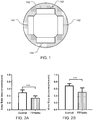
- the electrode pairs 141-142 and 143-144 were positioned in the Petri dish 150 perpendicular to each other with the geometry depicted in FIG. 1 .
- the electrodes 141-143 were connected to a modified Novocure Optune® system, which applied the appropriate AC signals to the electrodes 141-143 in order to generate TTFields in the target region.
- the TTFields changed direction by 90° every 1 second. This was accomplished by (a) applying the AC signal between electrodes 141 and 142 for 1 s, then (b) applying the AC signal between electrodes 143 and 144 for 1 s, and then repeating that (a) + (b) sequence for the course of the experiment. Temperature was measured by thermistors (not shown) incorporated into the dishes 150.
- the U-87 MG and A-172 cells were scratched and imaged. Migration was observed in time-lapse series for 24h (Zeiss axio observer; per 10 objective). Phase contrast images were recorded every 12 min. Baseline images of the scratch at 0 hours and cells that migrated into the scratch area 14 hours later were examined, at the same reference points. The obtained images were further evaluated to quantify cell migration rates during wound healing using the Image Pro Premier (Media Cybernetics, USA) software. Quantitative analysis of migration rate was performed, calculated as the total distance that the cells moved from the edge of the scratch toward the mid-center of the scratch as a function of time.
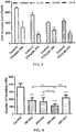
- FIGS. 2A and 2B summarize the results of the quantitative analysis for this first experiment.
- Cell migration rate was significantly reduced in TTFields treated U-87 MG (31%) and A-172 (27%) cell lines, compared with untreated control cells, as seen in FIG. 2A and FIG. 2B , respectively (mean+SEM; ***p ⁇ 0.001 from control group, student's t-test).
- the experiment was repeated 3 times.
- TTFields were applied using the Novocure Inovitro system by means of perpendicular pairs of electrodes insulated by a high dielectric constant ceramic (200 kHz, 0.6 V/cm RMS). The geometry of the electrodes for this experiment was similar to the geometry depicted in FIG. 1 , and the direction of the field was switched every 1 s (as described above for the first experiment).
- Inovitro dishes with extended vertical walls were used to facilitate effective delivery of TTFields through the transwell.
- the U-87 MG, A-172, LN-229 and LN-18 cells (2x10 5 ) were suspended in serum free DMEM and seeded on the upper compartment of the chamber.
- the lower compartment contained 10% FBS DMEM.
- the cells that invaded to the bottom filter were fixed with 4% PFA, stained with 0.5% crystal violet (Sigma) and imaged under inverted microscope (Nikon eclipse TS100; upper panel-control, Lower panel-TTFields treated cells; Objective x10). Quantification of invading cells was performed using ImageJ software (NIH).
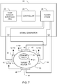
- FIG. 3 summarizes the results of the quantification for this second experiment.
- the number of invading cells was significantly reduced in all TTFields treated cell lines: U-87 MG (54%), A-172 (68%), LN-229 (38%) and in LN-18 (55%) compared with untreated control cells (mean+SEM; *p ⁇ 0.05, **p ⁇ 0.01, ***p ⁇ 0.001 from control group, student's t-test).
- TTFields hinder cell invasion in different glioma cell lines. It is noteworthy that duration of this invasion experiments (24 hours) was shorter than the duration (72 hours) that is ordinarily required for the anti-mitotic effect of TTFields.
- a third experiment was conducted to study the frequency dependence of TTFields' inhibition of U-87 glioma cancer cells invasive potential.
- a U-87 invasion assay was performed using modified Boyden chamber as described above in connection with the second experiment.
- TTFields were applied in various frequencies (100, 200, 300, and 400 kHz) using the same nominal intensity of 0.6 V/cm RMS and the same direction switching described above in connection with the first experiment. After incubation for 24 hours at 37°C in a 5% CO2 incubator, the cells that invaded to the bottom filter were fixed, imaged and quantified as described above in connection with the second experiment.
- FIG. 4 summarizes the results of the quantification for this third experiment.
- the number of invading cells was reduced (with respect to the control) for all four frequencies of TTFields tested in a frequency dependent manner; and the maximal reduction in the number of invading cells was observed at a frequency of 300 kHz. Perhaps most notably, the frequency that provided the highest reduction in the invasion potential was different from the 200 kHz frequency that provides (based on previous experiments) the highest anti-mitotic effect in U-87 cells.
- A-172 cells were scratched in 2 perpendicular directions and imaged. Migration was observed in time-lapse series for 24h as described. The obtained images were further evaluated to quantify cell migration rates during wound healing using the Image Pro Premier (Media Cybernetics, USA) software. Quantitative analysis of migration rate calculated as the total distance that the cells moved from the edge of the scratch toward the mid-center of the scratch as a function of time.
- FIG. 5 summarizes the results of the quantitative analysis for this fourth experiment.
- Cell migration rate was significantly reduced in as compared to the control when cells were migrating in parallel (24%) with the electric field, which was similar to the reduction obtained when the TTFields were applied from two different directions and switched every second (27%).
- TTFields applied from a single direction, perpendicular to the migration course resulted in the highest reduction in the migration rate (39%) which was significantly higher than the reduction obtained when TTFields were applied in two directions or a single direction in parallel with the course of migration (***p ⁇ 0.001 from both groups, student's t-test.
- the experiment was repeated 3 times).
- Bumetanide is a loop diuretic of the sulfamyl category to treat heart failure, and it is known to affect cellular motility.
- bumetanide blocks the NKCC1 cation-chloride co-transporter, and thus decreases internal chloride concentration in neurons.
- NKCC1 provides the major pathway for Cl - accumulation in glioma cells.
- NKCC1 localizes to the leading edge of invading processes, and pharmacologic inhibition using the loop diuretic bumetanide inhibits in vitro Transwell migration by 25% to 50%.
- FIG. 6 summarizes the results of the quantification for this fifth experiment.
- the number of invading cells was significantly reduced in cells treated by TTFields (31%) or Bumetanide (34%) applied alone (***p ⁇ 0.001 from control group, student's t-test).
- the combined treatment using both TTFields and Bumetanide led to a synergistic 61% reduction in the number of invading cells which was significantly higher than the reduction obtained by TTFields or Bumetanide applied alone (***p ⁇ 0.001, student's t-test).
- the current version of Novocure's Optune® system generates AC electric fields in a target region at a single frequency, and that frequency is selected in advance to increase the effectiveness of the field at disrupting mitosis of cancer cells within the target region.
- the Optune® system sometimes reduces the strength of the electric field to prevent overheating of the patient's skin, which renders the field less effective for disrupting mitosis.
- the embodiments described below take advantage of two outcomes of the second and third experiment described above.
- the embodiments described below take advantage of the facts that (1) the electric field intensity that is needed to cause a reduction in motility is lower than the electric field intensity that is ordinarily required for the anti-mitotic effect of TTFields; and (2) for at least certain cell lines, the frequency that provided the highest reduction in motility is different from the frequency that provides highest anti-mitotic effect.
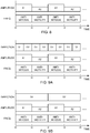
- FIG. 7 depicts an embodiment of the invention that includes a signal generator 20 and four electrodes 41-44 (also referred to as transducer arrays).
- the electrodes 41-44 are positioned so that they can induce an electric field in the target region 50.
- the electrodes 41-44 may be positioned in contact with the walls of the Petri dish that contains cancer cells 55.
- the electrodes 41-44 may be positioned in contact with the patient's skin in the vicinity of a tumor that includes cancer cells 55.
- the signal generator 20 has two outputs Q1 and Q2.
- the first output Q1 is connected across electrodes 41 and 42; and the second output Q2 is connected across the electrodes 43 and 44.
- the signal generator 20 outputs an AC voltage at output Q1, that voltage will appear across the electrodes 41, 42 and induce an electric field in the target region 50 in a first direction D1.
- the signal generator 20 outputs an AC voltage at output Q2, that voltage will appear across the electrodes 43, 44 and induce an electric field in the target region 50 in a second direction D2.
- Temperature sensors 48 detect the temperature at the electrodes 41-44 and report those temperatures back to a temperature sensor interface 22 contained within the signal generator 20. If the detected temperature is too high, the controller 25 will command the power stage 28 of the signal generator 20 to reduce its output voltage, which will ultimately bring the temperature down.
- FIG. 7 embodiment is distinguishable from Optune® because the Optune® field generator unit always outputs the same frequency. More specifically, the Optune® field generator unit always outputs a frequency that was preselected based on its anti-mitotic effect on the relevant cancer (i.e., 200 kHz in the context of glioblastoma). In contrast, the FIG. 7 embodiment switches the frequency of its outputs Q1, Q2 between a first frequency that is selected to disrupt mitosis of the cancer cells and a second frequency that is selected to reduce the motility of the cancer cells. This is accomplished in the FIG.
- controller 25 which outputs appropriate control signals to the power stage 28 in order to control the frequency and amplitude of the outputs Q1 and Q2 as described below in connection with FIGS. 8-9 .
- the controller 25 may be implemented using any of a variety of techniques that will be apparent to persons skilled in the relevant arts. Examples include but are not limited to a microprocessor or microcontroller-based controllers that are programmed to implement the sequences described herein; and hardware timers that generate appropriate control signals to orchestrate the sequences described herein.
- the hardware implementation of the power stage 28 is configured to respond to the control signals that are generated by the controller 25.
- FIG. 8 depicts a first sequence of events for the outputs Q1 and Q2 generated by the power stage 28 under control of the controller 25.
- the direction of the field is never switched, which means that only one of the outputs of the power stage (i.e. either Q1 or Q2) is necessary, and only one pair of electrodes (i.e., either 41/42 or 43/44) is necessary.
- the sequence for the lower half of FIG. 8 is as follows: First, between t0 and t1, a first AC electric field at a first frequency that is selected to disrupt mitosis of the cancer cells is imposed in the target region. Then, between t1 and t2, a second AC electric field at a second frequency that is selected to reduce motility of the cancer cells is imposed in the target region. This sequence is then repeated until the course of treatment ends.
- the amplitude of the signal generator' output is also switched in synchrony (as shown in the upper half of FIG. 8 ).
- sequence of events for the outputs generated by the power stage 28 under control of the controller 25 is as follows.
- a first AC electric field is imposed in the target region for a first interval of time (e.g., the interval between t0 and t1).
- the first AC electric field has a first frequency and a first amplitude, and the first frequency and the first amplitude are selected so that the first AC electric field disrupts mitosis of the cancer cells.
- a second AC electric field is imposed in the target region for a second interval of time (e.g., the interval between t1 and t2).
- the second AC electric field has a second frequency and a second amplitude, and the second frequency and the second amplitude are selected so that the second AC electric field reduces motility of the cancer cells.
- the second amplitude is lower than the first amplitude.
- steps (a) and (b) are then continuously repeated in an alternating sequence during a course of treatment.
- additional intervening steps may be added between step (a) and step (b) or between step (b) and step (a).
- the controller 25 may command the power stage 28 to output a third frequency between one or more instances of step (a) and step (b).
- the second amplitude (during the anti-motility phase) is lower than the first amplitude (during the anti-mitosis phase). But this is not problematic because the electric field intensity that is needed to cause a reduction in motility is lower than the electric field intensity that is ordinarily required for the anti-mitotic effect of TTFields. And advantageously, the system can rely on the reduced amplitude during the anti-motility phase to reduce the temperature at the electrodes without reducing the field strength during the anti-mitosis phase (which requires a higher amplitude).
- this advantage is compounded by the fact that the temperature rise is proportional to the square of the amplitude.
- lowering the amplitude during the anti-motility phase by X % will lower the heating during that phase to (1-X) 2 %.
- lowering the amplitude from 2 V/cm to 1 V/cm during the anti-motility phase will lower the heating during that phase to (1-0.5) 2 % (i.e., to one quarter of its original value). If we assume that the anti-motility phase and the anti-mitosis phases have the same duration, this modification would reduce the overall heating load to 5/8 of its original value.
- the second amplitude is less than 75% of the first amplitude.
- both the first interval of time and the second interval of time are less than five seconds. This can be important for sustaining the anti-mitosis affect without interruption.
- the course of treatment has a duration of at least 12 hours.
- the first frequency and the second frequency are different. In other embodiments, the first frequency and the second frequency could be the same (i.e., for cell lines in which the anti-mitosis frequency coincides with the anti-motility frequency).
- the first frequency i.e., the anti-mitosis frequency
- the second frequency i.e., the anti-motility frequency
- the second amplitude is at least 0.6 V/cm RMS, in order to maintain the anti-mobility effect.
- a compound that inhibits cell motility e.g., Bumetanide
- the direction of the electric field in the target region can also be switched between two or more directions.
- FIGS. 9A and 9B depict two examples in which the direction of the field is switched between the two directions D1 and D2 shown in FIG. 7 .
- the field is generated in the direction D1 when the signal generator 20 generates its output Q1, which is applied between electrodes 41 and 42.
- the field is generated in the direction D2 when the signal generator 20 generates its output Q2, which is applied between electrodes 43 and 44.
- FIG. 9A depicts the sequence of events for the outputs Q1 and Q2 generated by the power stage 28 of the signal generator 20 under control of the controller 25 in one such embodiment.
- the direction is switched between the two directions D1 and D2 at a rate that is faster than the rate at which the frequency is switched.
- the sequence here is similar to the sequence described above in connection with FIG. 8 in which both the frequency and the amplitude are switched in synchrony with each other. But in addition to switching the frequency and the amplitude as described above in connection with FIG. 8 , the direction of the field is also switched.
- the first AC electric field is imposed in the target region in a first direction for a first portion of the first interval of time (i.e., the first portion of the time between t0 and t1), and the first AC electric field is imposed in the target region in a second direction for a second portion of the first interval of time (i.e., the last portion of the time between t0 and t1).
- the angle between the first direction D1 and the second direction D2 is between 60° and 90°. (Note that all numeric angular ranges used herein are inclusive of the endpoints.)
- the direction in addition to switching the directions during the first interval of time (which corresponds to the anti-mitosis phase), the direction is also be switched during the second interval of time (which corresponds to the anti-motility phase).
- the second AC electric field is imposed in the target region in the first direction for a first portion of the second interval of time (i.e., the first portion of the time between t1 and t2), and the second AC electric field is imposed in the target region in the second direction for a second portion of the second interval of time (i.e., the last portion of the time between t1 and t2).
- FIG. 9B depicts the sequence of events for the outputs Q1 and Q2 generated by the power stage 28 under control of the controller 25 in another embodiment.
- the direction is switched between the two directions D1 and D2 at a rate that is slower than the rate at which the frequency is switched.
- the sequence here is similar to the sequence described above in connection with FIG. 8 in which both the frequency and the amplitude are switched in synchrony with each other. But in addition to the switching of the frequency and the amplitude described above in connection with FIG. 8 , the direction of the first AC electric field is changed during at least some of the repeating steps, and the direction of the second AC electric field is also changed during at least some of the repeating steps.
- FIG. 8 depicts the sequence of events for the outputs Q1 and Q2 generated by the power stage 28 under control of the controller 25 in another embodiment.
- the direction is switched between the two directions D1 and D2 at a rate that is slower than the rate at which the frequency is switched.
- the sequence here is similar to the sequence described above in connection with
- the original sequence corresponds to the interval of time between t0 and t2, and that original sequence is repeated during the course of the treatment, with the first repetition occupying the interval of time between t2 and t4.
- the direction of the fields for both the anti-mitosis stage and the anti-migration stage was switched to D2 during the first repetition with respect to the original sequence.
- step (a) a first AC electric field is imposed in the target region.
- the first AC electric field has a first frequency and a first amplitude that are selected so that the first AC electric field disrupts mitosis of the cancer cells.
- step (b) a second AC electric field is imposed in the target region.
- the second AC electric field has a second frequency and a second amplitude that are selected so that the second AC electric field reduces motility of the cancer cells.
- the second frequency and the first frequency are different, and the second amplitude is lower than the first amplitude.
- Some embodiments are directed to a method for treating cancer by exposing the primary tumor or its vicinity, metastases, or organs with high probability of metastatic uptake to alternating electric fields at a frequency optimally picked to inhibit the migration or invasion of the tumor cells. At least for certain cell lines, this frequency is significantly different from the frequency required to disrupt mitosis.
- the field may be delivered using Novocure's Optune® system or the devices described in US patents 7089054 , 6868289 , and 7706890 , which are incorporated herein by reference. It may be used to treat GBM or other types of cancer.
- the field may be delivered in a preferential direction, and the preferential direction chosen to prevent progression into non-resectable areas, or vital organs.
- the optimal frequency for inhibiting cell migration of a specific cancer cell type may be determined by culturing the cells (or a cell line that closely resembles the cells of interest) in petri dishes, exposing the cells to alternating electric fields at a given intensity, and at different frequencies, and finding the frequency that has the maximal inhibitory effect on cell migration for this specific cell line.
- the effect of the electric field may be determined via scratch assays and/or via an invasion assay.
- Some embodiments are directed to a method for treating cancer, whereby the tumor is exposed to alternating electric fields containing components at two frequencies: One frequency is the frequency that is optimal to inhibit cell division, and the other frequency optimal to inhibit migration. Note that combining two different frequencies tuned to damage dividing cells is described in US patent 8244345 , which is incorporated herein by reference. But here, one of the frequencies is tuned to prevent migration instead.
- the signals at the different frequencies may be applied sequentially, or they may be combined into a single field.
- the fields may be delivered in one direction or a plurality of different directions.
Landscapes
- Health & Medical Sciences (AREA)
- Life Sciences & Earth Sciences (AREA)
- Animal Behavior & Ethology (AREA)
- General Health & Medical Sciences (AREA)
- Public Health (AREA)
- Veterinary Medicine (AREA)
- Engineering & Computer Science (AREA)
- Nuclear Medicine, Radiotherapy & Molecular Imaging (AREA)
- Biomedical Technology (AREA)
- Radiology & Medical Imaging (AREA)
- Chemical & Material Sciences (AREA)
- Medicinal Chemistry (AREA)
- Pharmacology & Pharmacy (AREA)
- Oncology (AREA)
- Hospice & Palliative Care (AREA)
- Chemical Kinetics & Catalysis (AREA)
- Bioinformatics & Cheminformatics (AREA)
- Epidemiology (AREA)
- General Chemical & Material Sciences (AREA)
- Organic Chemistry (AREA)
- Physics & Mathematics (AREA)
- General Physics & Mathematics (AREA)
- Automation & Control Theory (AREA)
- Electrotherapy Devices (AREA)
- Medicines That Contain Protein Lipid Enzymes And Other Medicines (AREA)
Description
- TTFields are an effective and FDA approved approach for treating tumors. Treatment using TTFields involves the continuous, noninvasive application of low intensity, intermediate frequency, alternating electric fields to a target region that includes the tumor. Previous investigations have shown that TTFields disrupt of microtubules and septin filaments, both of which govern key roles in mitosis.
- Novocure's Optune® system is the current state of the art for treating glioblastoma using TTFields. Optune® uses a set of electrodes (also referred to as transducer arrays) that are positioned on a patient's body in the vicinity of the tumor. The Optune® field generator unit applies AC signals to those electrodes so as to induce an AC electric field in a target region that includes the tumor.
- The Optune® system works best when the strength of the AC electric field in the tumor is > 1 V/cm RMS, and increasing the field strength to between 2 and 3 V/cm RMS generally provides improved results. But thermal considerations often limit the strength of the AC electric field that can be delivered to the target region. More specifically, because the patient's skin must be protected from overheating, the Optune® system detects the temperature beneath the transducer arrays, and sometimes reduces the strength of the electric field to keep that temperature from exceeding 41° C. Unfortunately, the safety and comfort benefits provided by this temperature control tactic are accompanied by a drawback: the reduced-strength field is less effective at disrupting mitosis than a full-strength field.
- The present invention is defined by
claim 1 and is directed to an apparatus for inhibiting spreading of cancer cells in a target region. This apparatus comprises an AC signal generator having (i) a first controllable output configured to apply an AC voltage across a first set of capacitively coupled electrodes that are positioned in a vicinity of the target region, so as to impose an electric field in the target region in a first direction and (ii) a second controllable output configured to apply an AC voltage across a second set of capacitively coupled electrodes that are positioned in the vicinity of the target region, so as to impose an electric field in the target region in a second direction. This apparatus also comprises a controller configured to (a) control the first controllable output so that a first AC signal is generated for a first interval of time, the first AC signal having a first frequency and a first amplitude. The first frequency and the first amplitude are selected to impose an electric field that disrupts mitosis of the cancer cells. The controller is also configured to (b) control the first controllable output so that a second AC signal is generated for a second interval of time, the second AC signal having a second frequency and a second amplitude. The second frequency and the second amplitude are selected to impose an electric field that reduces motility of the cancer cells, and the second amplitude is lower than the first amplitude. The controller is also configured to (c) control the second controllable output so that a third AC signal is generated for a third interval of time, the third AC signal having a third frequency and a third amplitude. The third frequency and the third amplitude are selected to impose an electric field that disrupts mitosis of the cancer cells. The controller is also configured to (d) control the second controllable output so that a fourth AC signal is generated for a fourth interval of time. The fourth AC signal has a fourth frequency and a fourth amplitude. The fourth frequency and the fourth amplitude are selected to impose an electric field that reduces motility of the cancer cells, and the fourth amplitude is lower than the third amplitude. The controller is also configured to continuously repeat (a) through (d) in an alternating sequence during a course of treatment. - In some embodiments of the apparatus, the second amplitude is less than 75% of the first amplitude and the fourth amplitude is less than 75% of the third amplitude. In some embodiments of the apparatus, the second frequency and the first frequency are different, and the fourth frequency and the third frequency are different.
- In some embodiments of the apparatus, the second amplitude is less than 75% of the first amplitude, the fourth amplitude is less than 75% of the third amplitude, the second frequency and the first frequency are different, the fourth frequency and the third frequency are different, the third frequency is the same as the first frequency, the fourth frequency is the same as the second frequency, the first interval of time is less than 5 seconds, the second interval of time is less than 5 seconds, the third interval of time is less than 5 seconds, and the fourth interval of time is less than 5 seconds.
- In some embodiments of the apparatus, the first frequency is 200 kHz ± 10%, the second frequency is 300 kHz ± 10%, the third frequency is 200 kHz ± 10%, and the fourth frequency is 300 kHz ± 10%.
- Further embodiments disclosed herein, in particular embodiments relating to a method for treating cancer, are for exemplary purposes only, and do not form part of the claimed invention.
-
-
FIG. 1 depicts an arrangement of electrodes in a Petri dish used to conduct some of the experiments described herein. -
FIGS. 2A and 2B depicts the results of cell migration rate experiments that studied TTFields' effects on two different cell lines. -
FIG. 3 depicts the results of cell invasion experiments that studied TTFields' effects on four different cell lines. -
FIG. 4 depicts the results of cell invasion experiments that studied the frequency dependence of TTFields' inhibition of U-87 glioma. -
FIG. 5 depicts the results of cell migration rate experiments that studied the directional dependence of TTFields' inhibition of glioma cancer cells. -
FIG. 6 depicts the results of cell invasion experiments that compares the efficacy of TTFields to the efficacy of Bumetanide in inhibiting glioma cancer cells. -
FIG. 7 depicts an embodiment of the invention that includes a signal generator and electrodes. -
FIG. 8 depicts a first sequence of events for the outputs of the signal generator of theFIG. 7 embodiment. -
FIGS. 9A and 9B depict additional sequences of events for the outputs of the signal generator of theFIG. 7 embodiment. - The ability of glioblastoma cells to invade adjacent brain tissue can make it difficult to control glioblastoma. The development of treatment modalities that hinder glioma cancer cell motility could therefore facilitate disease control.
- The inventors have determined that, in addition to having antimitotic effects, TTFields have an impact on other cellular processes that require proper microtubule dynamics. One such process, which has a major impact on glioblastoma progression, is cell motility. This application documents the effects of TTFields on cell motility, including both the migration and invasion properties of glioma cells. This application also describes methods and systems for reducing cell motility by applying TTFields to cancer cells in a target region.
- A set of experiments was run to evaluate the effect of TTFields on human glioma cell motility, including the migration and invasion properties of those cells.
- The first experiment used scratch wound assays in vitro to determine the effects of TTFields on migration of U-87 MG and A-172 glioma cells. In this experiment, in vitro wound assays were performed using IBIDI culture-inserts. TTFields (200 kHz, 1.75 RMS) were applied using two pairs of electrodes 141-142 and 143-144 that were insulated by a high dielectric constant ceramic (ε >5000) (Exelis, Salt Lake City, Utah). The electrode pairs 141-142 and 143-144 were positioned in the
Petri dish 150 perpendicular to each other with the geometry depicted inFIG. 1 . The electrodes 141-143 were connected to a modified Novocure Optune® system, which applied the appropriate AC signals to the electrodes 141-143 in order to generate TTFields in the target region. The TTFields changed direction by 90° every 1 second. This was accomplished by (a) applying the AC signal betweenelectrodes electrodes dishes 150. - The U-87 MG and A-172 cells were scratched and imaged. Migration was observed in time-lapse series for 24h (Zeiss axio observer; per 10 objective). Phase contrast images were recorded every 12 min. Baseline images of the scratch at 0 hours and cells that migrated into the scratch area 14 hours later were examined, at the same reference points. The obtained images were further evaluated to quantify cell migration rates during wound healing using the Image Pro Premier (Media Cybernetics, USA) software. Quantitative analysis of migration rate was performed, calculated as the total distance that the cells moved from the edge of the scratch toward the mid-center of the scratch as a function of time.
-
FIGS. 2A and 2B summarize the results of the quantitative analysis for this first experiment. Cell migration rate was significantly reduced in TTFields treated U-87 MG (31%) and A-172 (27%) cell lines, compared with untreated control cells, as seen inFIG. 2A and FIG. 2B , respectively (mean+SEM; ***p < 0.001 from control group, student's t-test). The experiment was repeated 3 times. These results indicate that TTFields hinder cell migration in different glioma cell lines. - In a second experiment, an invasion assay was performed using a modified Boyden chamber to determine the effects of TTFields on invasion for U-87 MG, A-172, LN-229 and LN-18 cells. Filters (6.4 mm in diameter, 8 µm pore size) coated with Matrigel (Corning) were used. TTFields were applied using the Novocure Inovitro system by means of perpendicular pairs of electrodes insulated by a high dielectric constant ceramic (200 kHz, 0.6 V/cm RMS). The geometry of the electrodes for this experiment was similar to the geometry depicted in
FIG. 1 , and the direction of the field was switched every 1 s (as described above for the first experiment). Inovitro dishes with extended vertical walls were used to facilitate effective delivery of TTFields through the transwell. The U-87 MG, A-172, LN-229 and LN-18 cells (2x10⁵) were suspended in serum free DMEM and seeded on the upper compartment of the chamber. The lower compartment contained 10% FBS DMEM. After incubation for 24 hours at 37°C in a 5% CO2 incubator, the cells that invaded to the bottom filter, were fixed with 4% PFA, stained with 0.5% crystal violet (Sigma) and imaged under inverted microscope (Nikon eclipse TS100; upper panel-control, Lower panel-TTFields treated cells; Objective x10). Quantification of invading cells was performed using ImageJ software (NIH). -
FIG. 3 summarizes the results of the quantification for this second experiment. The number of invading cells was significantly reduced in all TTFields treated cell lines: U-87 MG (54%), A-172 (68%), LN-229 (38%) and in LN-18 (55%) compared with untreated control cells (mean+SEM; *p < 0.05, **p < 0.01, ***p < 0.001 from control group, student's t-test). These results indicate that TTFields hinder cell invasion in different glioma cell lines. It is noteworthy that duration of this invasion experiments (24 hours) was shorter than the duration (72 hours) that is ordinarily required for the anti-mitotic effect of TTFields. It was also noteworthy that the electric field intensity (i.e., 0.6 V/cm RMS) that caused this reduction in invasion was lower than the electric field intensity (i.e., > 1 V/cm RMS) that is ordinarily required for the anti-mitotic effect of TTFields. - A third experiment was conducted to study the frequency dependence of TTFields' inhibition of U-87 glioma cancer cells invasive potential. A U-87 invasion assay was performed using modified Boyden chamber as described above in connection with the second experiment. TTFields were applied in various frequencies (100, 200, 300, and 400 kHz) using the same nominal intensity of 0.6 V/cm RMS and the same direction switching described above in connection with the first experiment. After incubation for 24 hours at 37°C in a 5% CO2 incubator, the cells that invaded to the bottom filter were fixed, imaged and quantified as described above in connection with the second experiment.
-
FIG. 4 summarizes the results of the quantification for this third experiment. The number of invading cells was reduced (with respect to the control) for all four frequencies of TTFields tested in a frequency dependent manner; and the maximal reduction in the number of invading cells was observed at a frequency of 300 kHz. Perhaps most notably, the frequency that provided the highest reduction in the invasion potential was different from the 200 kHz frequency that provides (based on previous experiments) the highest anti-mitotic effect in U-87 cells. - A fourth experiment was conducted to study the directional dependence of TTFields' inhibition of glioma cancer cells migration. TTFields (200 kHz, 1.75 RMS) were applied using two pairs of electrodes, insulated by a high dielectric constant ceramic (ε >5000) (Exelis, Salt Lake City, Utah) positioned in the Petri dish. The geometry of the electron pairs was similar to the geometry shown in
FIG. 1 . In vitro wound assays were performed using IBIDI culture-inserts with 2 inserts placed in each dish, one in parallel with the electric field and one perpendicular to the direction of the electric field. The electrodes were connected to a modified Optune® system that applied AC signals to the electrodes in order to generate the electric field in the various directions required for this experiment. Temperature was measured by thermistors incorporated into the dishes. - A-172 cells were scratched in 2 perpendicular directions and imaged. Migration was observed in time-lapse series for 24h as described. The obtained images were further evaluated to quantify cell migration rates during wound healing using the Image Pro Premier (Media Cybernetics, USA) software. Quantitative analysis of migration rate calculated as the total distance that the cells moved from the edge of the scratch toward the mid-center of the scratch as a function of time.
-
FIG. 5 summarizes the results of the quantitative analysis for this fourth experiment. Cell migration rate was significantly reduced in as compared to the control when cells were migrating in parallel (24%) with the electric field, which was similar to the reduction obtained when the TTFields were applied from two different directions and switched every second (27%). Interestingly, TTFields applied from a single direction, perpendicular to the migration course, resulted in the highest reduction in the migration rate (39%) which was significantly higher than the reduction obtained when TTFields were applied in two directions or a single direction in parallel with the course of migration (***p < 0.001 from both groups, student's t-test. The experiment was repeated 3 times). These results indicate that the direction of the applied electric fields have different effect on the migration rates depending on the course of migration. - A fifth experiment was conducted to compare the efficacy of TTFields to the efficacy of Bumetanide in inhibiting glioma cells invasive potential. Bumetanide is a loop diuretic of the sulfamyl category to treat heart failure, and it is known to affect cellular motility. In the brain, bumetanide blocks the NKCC1 cation-chloride co-transporter, and thus decreases internal chloride concentration in neurons. NKCC1 provides the major pathway for Cl- accumulation in glioma cells. NKCC1 localizes to the leading edge of invading processes, and pharmacologic inhibition using the loop diuretic bumetanide inhibits in vitro Transwell migration by 25% to 50%.
- An invasion assay was performed as described above in connection with the second experiment with some minor modifications. More specifically, U-87 cells (2x10⁵) were suspended in serum free DMEM and seeded in the upper compartment of the chamber. The lower compartment contained 10% FBS DMEM. Both compartments contained Bumetanide in the concentration of 200 µM. TTFields were applied as described above (200 kHz, 0.6 V/cm RMS). After incubation for 24 hours at 37°C in a 5% CO2 incubator, the cells that invaded to the bottom filter, were fixed, stained with crystal violet, and imaged under inverted microscopes. Quantification of invading cells was performed using ImageJ software (NIH).
-
FIG. 6 summarizes the results of the quantification for this fifth experiment. The number of invading cells was significantly reduced in cells treated by TTFields (31%) or Bumetanide (34%) applied alone (***p < 0.001 from control group, student's t-test). And notably, the combined treatment using both TTFields and Bumetanide led to a synergistic 61% reduction in the number of invading cells which was significantly higher than the reduction obtained by TTFields or Bumetanide applied alone (***p < 0.001, student's t-test). These results indicate that exposure to low intensities TTFields in combinations with drugs that inhibit cell motility could lead to a synergistic enhanced inhibitory effect on glioma cells invasiveness as compared to either treatment alone. And more specifically, combining TTFields with Bumetanide resulted in a synergistic enhanced efficacy as compared to either treatment alone. - The current version of Novocure's Optune® system generates AC electric fields in a target region at a single frequency, and that frequency is selected in advance to increase the effectiveness of the field at disrupting mitosis of cancer cells within the target region. As indicated above, the Optune® system sometimes reduces the strength of the electric field to prevent overheating of the patient's skin, which renders the field less effective for disrupting mitosis. The embodiments described below take advantage of two outcomes of the second and third experiment described above. More specifically, the embodiments described below take advantage of the facts that (1) the electric field intensity that is needed to cause a reduction in motility is lower than the electric field intensity that is ordinarily required for the anti-mitotic effect of TTFields; and (2) for at least certain cell lines, the frequency that provided the highest reduction in motility is different from the frequency that provides highest anti-mitotic effect.
-
FIG. 7 depicts an embodiment of the invention that includes asignal generator 20 and four electrodes 41-44 (also referred to as transducer arrays). The electrodes 41-44 are positioned so that they can induce an electric field in thetarget region 50. For example, if the target region is a petri dish, the electrodes 41-44 may be positioned in contact with the walls of the Petri dish that containscancer cells 55. Alternatively, if the target region is a portion of a patient's body, the electrodes 41-44 may be positioned in contact with the patient's skin in the vicinity of a tumor that includescancer cells 55. Thesignal generator 20 has two outputs Q1 and Q2. The first output Q1 is connected acrosselectrodes electrodes signal generator 20 outputs an AC voltage at output Q1, that voltage will appear across theelectrodes target region 50 in a first direction D1. When thesignal generator 20 outputs an AC voltage at output Q2, that voltage will appear across theelectrodes target region 50 in a second direction D2.Temperature sensors 48 detect the temperature at the electrodes 41-44 and report those temperatures back to atemperature sensor interface 22 contained within thesignal generator 20. If the detected temperature is too high, thecontroller 25 will command thepower stage 28 of thesignal generator 20 to reduce its output voltage, which will ultimately bring the temperature down. - Note that the description of
FIG. 7 in the previous paragraph is very similar to the operation of the current version of the Novocure Optune® system. But theFIG. 7 embodiment is distinguishable from Optune® because the Optune® field generator unit always outputs the same frequency. More specifically, the Optune® field generator unit always outputs a frequency that was preselected based on its anti-mitotic effect on the relevant cancer (i.e., 200 kHz in the context of glioblastoma). In contrast, theFIG. 7 embodiment switches the frequency of its outputs Q1, Q2 between a first frequency that is selected to disrupt mitosis of the cancer cells and a second frequency that is selected to reduce the motility of the cancer cells. This is accomplished in theFIG. 7 embodiment by thecontroller 25, which outputs appropriate control signals to thepower stage 28 in order to control the frequency and amplitude of the outputs Q1 and Q2 as described below in connection withFIGS. 8-9 . Thecontroller 25 may be implemented using any of a variety of techniques that will be apparent to persons skilled in the relevant arts. Examples include but are not limited to a microprocessor or microcontroller-based controllers that are programmed to implement the sequences described herein; and hardware timers that generate appropriate control signals to orchestrate the sequences described herein. The hardware implementation of thepower stage 28 is configured to respond to the control signals that are generated by thecontroller 25. -
FIG. 8 depicts a first sequence of events for the outputs Q1 and Q2 generated by thepower stage 28 under control of thecontroller 25. In this sequence, the direction of the field is never switched, which means that only one of the outputs of the power stage (i.e. either Q1 or Q2) is necessary, and only one pair of electrodes (i.e., either 41/42 or 43/44) is necessary. The sequence for the lower half ofFIG. 8 is as follows: First, between t0 and t1, a first AC electric field at a first frequency that is selected to disrupt mitosis of the cancer cells is imposed in the target region. Then, between t1 and t2, a second AC electric field at a second frequency that is selected to reduce motility of the cancer cells is imposed in the target region. This sequence is then repeated until the course of treatment ends. - In some embodiments, in addition to switching the frequency (as shown in the lower half of
FIG. 8 ), the amplitude of the signal generator' output is also switched in synchrony (as shown in the upper half ofFIG. 8 ). In these embodiments, sequence of events for the outputs generated by thepower stage 28 under control of thecontroller 25 is as follows. - In step (a), a first AC electric field is imposed in the target region for a first interval of time (e.g., the interval between t0 and t1). The first AC electric field has a first frequency and a first amplitude, and the first frequency and the first amplitude are selected so that the first AC electric field disrupts mitosis of the cancer cells. In step (b), a second AC electric field is imposed in the target region for a second interval of time (e.g., the interval between t1 and t2). The second AC electric field has a second frequency and a second amplitude, and the second frequency and the second amplitude are selected so that the second AC electric field reduces motility of the cancer cells. The second amplitude is lower than the first amplitude. These steps (a) and (b) are then continuously repeated in an alternating sequence during a course of treatment. Optionally, additional intervening steps may be added between step (a) and step (b) or between step (b) and step (a). For example, the
controller 25 may command thepower stage 28 to output a third frequency between one or more instances of step (a) and step (b). - As noted above, the second amplitude (during the anti-motility phase) is lower than the first amplitude (during the anti-mitosis phase). But this is not problematic because the electric field intensity that is needed to cause a reduction in motility is lower than the electric field intensity that is ordinarily required for the anti-mitotic effect of TTFields. And advantageously, the system can rely on the reduced amplitude during the anti-motility phase to reduce the temperature at the electrodes without reducing the field strength during the anti-mitosis phase (which requires a higher amplitude).
- Furthermore, this advantage is compounded by the fact that the temperature rise is proportional to the square of the amplitude. As a result, lowering the amplitude during the anti-motility phase by X % will lower the heating during that phase to (1-X)2 %. For example, lowering the amplitude from 2 V/cm to 1 V/cm during the anti-motility phase will lower the heating during that phase to (1-0.5)2 % (i.e., to one quarter of its original value). If we assume that the anti-motility phase and the anti-mitosis phases have the same duration, this modification would reduce the overall heating load to 5/8 of its original value.
- In some preferred embodiments, the second amplitude is less than 75% of the first amplitude. Preferably, both the first interval of time and the second interval of time are less than five seconds. This can be important for sustaining the anti-mitosis affect without interruption. Preferably, the course of treatment has a duration of at least 12 hours. In some preferred embodiments, the first frequency and the second frequency are different. In other embodiments, the first frequency and the second frequency could be the same (i.e., for cell lines in which the anti-mitosis frequency coincides with the anti-motility frequency). In some preferred embodiments, the first frequency (i.e., the anti-mitosis frequency) is 200 kHz ± 10% and the second frequency (i.e., the anti-motility frequency) is 300 kHz ± 10%. In some preferred embodiments, the second amplitude is at least 0.6 V/cm RMS, in order to maintain the anti-mobility effect. Optionally, a compound that inhibits cell motility (e.g., Bumetanide) may be administered during the course of treatment.
- In some embodiments, in addition to switching the frequency of the field between a first frequency optimized for disrupting mitosis and a second frequency optimized for reducing motility, the direction of the electric field in the target region can also be switched between two or more directions.
FIGS. 9A and 9B depict two examples in which the direction of the field is switched between the two directions D1 and D2 shown inFIG. 7 . The field is generated in the direction D1 when thesignal generator 20 generates its output Q1, which is applied betweenelectrodes signal generator 20 generates its output Q2, which is applied betweenelectrodes -
FIG. 9A depicts the sequence of events for the outputs Q1 and Q2 generated by thepower stage 28 of thesignal generator 20 under control of thecontroller 25 in one such embodiment. In this sequence, the direction is switched between the two directions D1 and D2 at a rate that is faster than the rate at which the frequency is switched. The sequence here is similar to the sequence described above in connection withFIG. 8 in which both the frequency and the amplitude are switched in synchrony with each other. But in addition to switching the frequency and the amplitude as described above in connection withFIG. 8 , the direction of the field is also switched. More specifically, the first AC electric field is imposed in the target region in a first direction for a first portion of the first interval of time (i.e., the first portion of the time between t0 and t1), and the first AC electric field is imposed in the target region in a second direction for a second portion of the first interval of time (i.e., the last portion of the time between t0 and t1). Preferably, the angle between the first direction D1 and the second direction D2 is between 60° and 90°. (Note that all numeric angular ranges used herein are inclusive of the endpoints.) - In some embodiments, in addition to switching the directions during the first interval of time (which corresponds to the anti-mitosis phase), the direction is also be switched during the second interval of time (which corresponds to the anti-motility phase). In these embodiments, the second AC electric field is imposed in the target region in the first direction for a first portion of the second interval of time (i.e., the first portion of the time between t1 and t2), and the second AC electric field is imposed in the target region in the second direction for a second portion of the second interval of time (i.e., the last portion of the time between t1 and t2).
-
FIG. 9B depicts the sequence of events for the outputs Q1 and Q2 generated by thepower stage 28 under control of thecontroller 25 in another embodiment. In this sequence, the direction is switched between the two directions D1 and D2 at a rate that is slower than the rate at which the frequency is switched. The sequence here is similar to the sequence described above in connection withFIG. 8 in which both the frequency and the amplitude are switched in synchrony with each other. But in addition to the switching of the frequency and the amplitude described above in connection withFIG. 8 , the direction of the first AC electric field is changed during at least some of the repeating steps, and the direction of the second AC electric field is also changed during at least some of the repeating steps. In the example ofFIG. 9B , the original sequence corresponds to the interval of time between t0 and t2, and that original sequence is repeated during the course of the treatment, with the first repetition occupying the interval of time between t2 and t4. As seen inFIG. 9B , the direction of the fields for both the anti-mitosis stage and the anti-migration stage was switched to D2 during the first repetition with respect to the original sequence. - Note that in the sequences depicted in
FIGS. 8-9 above, the anti-mitosis phase and the anti-motility phase are mutually exclusive with respect to time. However, in alternative embodiments, those phases may overlap with each other either partially or completely. An example of such an embodiment would be to implement the following two steps (a) and (b) simultaneously: In step (a), a first AC electric field is imposed in the target region. The first AC electric field has a first frequency and a first amplitude that are selected so that the first AC electric field disrupts mitosis of the cancer cells. In step (b), a second AC electric field is imposed in the target region. The second AC electric field has a second frequency and a second amplitude that are selected so that the second AC electric field reduces motility of the cancer cells. The second frequency and the first frequency are different, and the second amplitude is lower than the first amplitude. When steps all (a) and (b) are implemented simultaneously, the first and second AC electric fields will add by superposition. - Some embodiments are directed to a method for treating cancer by exposing the primary tumor or its vicinity, metastases, or organs with high probability of metastatic uptake to alternating electric fields at a frequency optimally picked to inhibit the migration or invasion of the tumor cells. At least for certain cell lines, this frequency is significantly different from the frequency required to disrupt mitosis. The field may be delivered using Novocure's Optune® system or the devices described in
US patents 7089054 ,6868289 7706890 - For different types of cancer, the optimal frequency for inhibiting cell migration of a specific cancer cell type may be determined by culturing the cells (or a cell line that closely resembles the cells of interest) in petri dishes, exposing the cells to alternating electric fields at a given intensity, and at different frequencies, and finding the frequency that has the maximal inhibitory effect on cell migration for this specific cell line. The effect of the electric field may be determined via scratch assays and/or via an invasion assay.
- Some embodiments are directed to a method for treating cancer, whereby the tumor is exposed to alternating electric fields containing components at two frequencies: One frequency is the frequency that is optimal to inhibit cell division, and the other frequency optimal to inhibit migration. Note that combining two different frequencies tuned to damage dividing cells is described in
US patent 8244345 , which is incorporated herein by reference. But here, one of the frequencies is tuned to prevent migration instead. The signals at the different frequencies may be applied sequentially, or they may be combined into a single field. The fields may be delivered in one direction or a plurality of different directions. - While the present invention has been disclosed with reference to certain embodiments, numerous modifications, alterations, and changes to the described embodiments are possible without departing from the scope of the present invention, as defined in the appended claims. Accordingly, it is intended that the present invention not be limited to the described embodiments, but by the following claims only.
Claims (5)
- An apparatus for inhibiting spreading of cancer cells in a target region (50), the apparatus comprising:an AC signal generator (20) having (i) a first controllable output (Q1) configured to apply an AC voltage across a first set of capacitively-coupled electrodes (41, 42) that are positioned in a vicinity of the target region (50), so as to impose an electric field in the target region (50) in a first direction (D1), and (ii) a second controllable output (Q2) configured to apply an AC voltage across a second set of capacitively-coupled electrodes (43, 44) that are positioned in the vicinity of the target region (50), so as to impose an electric field in the target region (50) in a second direction (D2); anda controller (25) configured to (a) control the first controllable output (Q1) so that a first AC signal is generated for a first interval of time, the first AC signal having a first frequency and a first amplitude (A1), wherein the first frequency and the first amplitude (A1) are selected to impose an electric field that disrupts mitosis of the cancer cells, (b) control the first controllable output (Q1) so that a second AC signal is generated for a second interval of time, the second AC signal having a second frequency and a second amplitude (A2), wherein the second frequency and the second amplitude (A2) are selected to impose an electric field that reduces motility of the cancer cells, and wherein the second amplitude (A2) is lower than the first amplitude (A1), (c) control the second controllable output (Q2) so that a third AC signal is generated for a third interval of time, the third AC signal having a third frequency and a third amplitude (A1), wherein the third frequency and the third amplitude (A1) are selected to impose an electric field that disrupts mitosis of the cancer cells, (d) control the second controllable output (Q2) so that a fourth AC signal is generated for a fourth interval of time, the fourth AC signal having a fourth frequency and a fourth amplitude (A2), wherein the fourth frequency and the fourth amplitude (A2) are selected to impose an electric field that reduces motility of the cancer cells, and wherein the fourth amplitude (A2) is lower than the third amplitude (A1), and (e) continuously repeat (a) through (d) in an alternating sequence during a course of treatment.
- The apparatus of claim 1, wherein the second amplitude (A2) is less than 75% of the first amplitude (A1) and the fourth amplitude (A2) is less than 75% of the third amplitude (A1).
- The apparatus of claim 1, wherein the second frequency and the first frequency are different, and the fourth frequency and the third frequency are different.
- The apparatus of claim 1, wherein the second amplitude (A2) is less than 75% of the first amplitude (A1), the fourth amplitude (A2) is less than 75% of the third amplitude (A1), the second frequency and the first frequency are different, the fourth frequency and the third frequency are different, the third frequency is the same as the first frequency, the fourth frequency is the same as the second frequency, the first interval of time is less than 5 seconds, the second interval of time is less than 5 seconds, the third interval of time is less than 5 seconds, and the fourth interval of time is less than 5 seconds.
- The apparatus of claim 1, wherein the first frequency is 200 kHz ± 10%, the second frequency is 300 kHz ± 10%, the third frequency is 200 kHz ± 10%, and the fourth frequency is 300 kHz ± 10%.
Priority Applications (3)
| Application Number | Priority Date | Filing Date | Title |
|---|---|---|---|
| PL17716642T PL3439733T3 (en) | 2016-04-04 | 2017-04-04 | Reducing motility of cancer cells using tumor treating fields (ttfields) |
| EP19219639.2A EP3693054B1 (en) | 2016-04-04 | 2017-04-04 | Reducing motility of cancer cells using tumor treating fields (ttfields) |
| EP23181273.6A EP4234005A3 (en) | 2016-04-04 | 2017-04-04 | Reducing motility of cancer cells using tumor treating fields (ttfields) |
Applications Claiming Priority (2)
| Application Number | Priority Date | Filing Date | Title |
|---|---|---|---|
| US201662317985P | 2016-04-04 | 2016-04-04 | |
| PCT/IB2017/051898 WO2017175116A1 (en) | 2016-04-04 | 2017-04-04 | Reducing motility of cancer cells using tumor treating fields (ttfields) |
Related Child Applications (2)
| Application Number | Title | Priority Date | Filing Date |
|---|---|---|---|
| EP19219639.2A Division EP3693054B1 (en) | 2016-04-04 | 2017-04-04 | Reducing motility of cancer cells using tumor treating fields (ttfields) |
| EP23181273.6A Division EP4234005A3 (en) | 2016-04-04 | 2017-04-04 | Reducing motility of cancer cells using tumor treating fields (ttfields) |
Publications (2)
| Publication Number | Publication Date |
|---|---|
| EP3439733A1 EP3439733A1 (en) | 2019-02-13 |
| EP3439733B1 true EP3439733B1 (en) | 2019-12-25 |
Family
ID=58530601
Family Applications (3)
| Application Number | Title | Priority Date | Filing Date |
|---|---|---|---|
| EP17716642.8A Active EP3439733B1 (en) | 2016-04-04 | 2017-04-04 | Reducing motility of cancer cells using tumor treating fields (ttfields) |
| EP23181273.6A Pending EP4234005A3 (en) | 2016-04-04 | 2017-04-04 | Reducing motility of cancer cells using tumor treating fields (ttfields) |
| EP19219639.2A Active EP3693054B1 (en) | 2016-04-04 | 2017-04-04 | Reducing motility of cancer cells using tumor treating fields (ttfields) |
Family Applications After (2)
| Application Number | Title | Priority Date | Filing Date |
|---|---|---|---|
| EP23181273.6A Pending EP4234005A3 (en) | 2016-04-04 | 2017-04-04 | Reducing motility of cancer cells using tumor treating fields (ttfields) |
| EP19219639.2A Active EP3693054B1 (en) | 2016-04-04 | 2017-04-04 | Reducing motility of cancer cells using tumor treating fields (ttfields) |
Country Status (12)
| Country | Link |
|---|---|
| US (2) | US10821283B2 (en) |
| EP (3) | EP3439733B1 (en) |
| JP (2) | JP6896839B2 (en) |
| KR (1) | KR102430229B1 (en) |
| CN (2) | CN109475735B (en) |
| CA (1) | CA3019474A1 (en) |
| DK (1) | DK3439733T3 (en) |
| ES (1) | ES2779990T3 (en) |
| HU (1) | HUE048646T2 (en) |
| PL (1) | PL3439733T3 (en) |
| PT (1) | PT3439733T (en) |
| WO (1) | WO2017175116A1 (en) |
Cited By (1)
| Publication number | Priority date | Publication date | Assignee | Title |
|---|---|---|---|---|
| EP4274550A1 (en) * | 2021-01-05 | 2023-11-15 | Telea Electronic Engineering Srl | Device and antitumor drug for the treatment of neoplastic cells |
Families Citing this family (82)
| Publication number | Priority date | Publication date | Assignee | Title |
|---|---|---|---|---|
| US10779875B2 (en) | 2013-05-06 | 2020-09-22 | Novocure Gmbh | Optimizing treatment using TTfields by changing the frequency during the course of long term tumor treatment |
| US10188851B2 (en) | 2015-10-28 | 2019-01-29 | Novocure Limited | TTField treatment with optimization of electrode positions on the head based on MRI-based conductivity measurements |
| US10821283B2 (en) * | 2016-04-04 | 2020-11-03 | Novocure Gmbh | Reducing motility of cancer cells using tumor treating fields (TTFields) |
| DK3474760T3 (en) | 2016-06-27 | 2023-03-20 | Galvanize Therapeutics Inc | Generator and a catheter with an electrode for treating a lung passage |
| US12403305B2 (en) | 2016-06-27 | 2025-09-02 | Galvanize Therapeutics, Inc. | Immunostimulation in the treatment of viral infection |
| US20180001075A1 (en) | 2016-06-30 | 2018-01-04 | Novocure Limited | Arrays for Longitudinal Delivery of TTFields to a Body |
| WO2018134733A1 (en) | 2017-01-19 | 2018-07-26 | Moshe Giladi | System for viewing cell cultures under a microscope whilst applying ttfields |
| US20190117969A1 (en) * | 2017-10-23 | 2019-04-25 | Cardiac Pacemakers, Inc. | Medical devices for treatment of cancer with electric fields |
| US11338135B2 (en) | 2017-10-23 | 2022-05-24 | Cardiac Pacemakers, Inc. | Medical devices for cancer therapy with electric field shaping elements |
| US12403306B2 (en) * | 2017-10-23 | 2025-09-02 | Cardiac Pacemakers, Inc. | Electric field shaping leads for treatment of cancer |
| WO2019100016A1 (en) * | 2017-11-17 | 2019-05-23 | Abbvie Inc. | Methods of treating glioblastoma |
| DK4218641T3 (en) | 2017-12-26 | 2025-08-18 | Galvanize Therapeutics Inc | OPTIMIZING ENERGY DELIVERY FOR VARIOUS APPLICATIONS |
| US10953209B2 (en) | 2018-03-28 | 2021-03-23 | Board Of Regents Of The University Of Texas System | Treating tumors using TTFields combined with a PARP inhibitor |
| WO2019197973A1 (en) | 2018-04-09 | 2019-10-17 | Moshe Giladi | Treating tumors with ttfields and an aurora kinase inhibitor |
| KR102687814B1 (en) | 2018-04-10 | 2024-07-24 | 지브 봄존 | Low-frequency alternating current conductivity estimates below 1 MHz obtained from two MRI images with different repetition times. |
| CN116159242A (en) * | 2018-07-03 | 2023-05-26 | 埃德温·阊 | Enhancement of cell membrane permeability using alternating electric fields |
| KR102794415B1 (en) * | 2018-07-10 | 2025-04-09 | 노보큐어 게엠베하 | Inhibition of viral infection using alternating electric fields |
| US11179322B2 (en) | 2018-07-10 | 2021-11-23 | Novocure Gmbh | Methods and compositions for treating tumors with TTFields and sorafenib |
| US11911612B2 (en) | 2018-07-18 | 2024-02-27 | Novocure Gmbh | Using power loss density and related measures to quantify the dose of tumor treating fields (TTFields) |
| EP3892219B1 (en) * | 2018-08-23 | 2022-06-01 | Novocure GmbH | Using alternating electric fields to increase permeability of the blood brain barrier |
| US11623085B2 (en) | 2018-08-29 | 2023-04-11 | Regents Of The University Of Minnesota | Devices and methods for treatment of tumors using electromagnetic signal |
| US11160977B2 (en) | 2018-09-04 | 2021-11-02 | Novocure Gmbh | Delivering tumor treating fields (TTFields) to the infratentorial brain |
| US11986647B2 (en) | 2018-09-07 | 2024-05-21 | Novocure Gmbh | Treating autoinflammatory and mitochondrial diseases using an alternating electric field |
| WO2020049482A1 (en) * | 2018-09-07 | 2020-03-12 | Yaniv Alon | Treating autoimmune diseases using an alternating electric field to reduce the proliferation of t-cells |
| EP3840823B1 (en) | 2018-10-15 | 2023-07-12 | Novocure GmbH | Generating tumor treating fields (ttfields) with high uniformity throughout the brain |
| WO2020084596A1 (en) | 2018-10-25 | 2020-04-30 | Zeev Bomzon | Delivering alternating electric fields (e.g., ttfields) to a subject's spinal anatomy |
| WO2020102312A1 (en) | 2018-11-13 | 2020-05-22 | The Methodist Hospital | Method and apparatus for oncomagnetic treatement |
| EP3922301B1 (en) * | 2018-11-19 | 2024-02-21 | Novocure GmbH | Arrays for delivering tumor treating fields (ttfields) with selectively addressable sub-elements |
| KR102606263B1 (en) | 2018-11-29 | 2023-11-23 | 노보큐어 게엠베하 | Enhanced Flexible Transducer Arrays Delivering Tumor Treatment Fields |
| EP3961565A1 (en) | 2019-01-08 | 2022-03-02 | Novocure GmbH | Evaluating quality of segmentation of an image into different types of tissue for planning treatment using tumor treating fields (ttfields) |
| KR102847999B1 (en) | 2019-02-26 | 2025-08-21 | 노보큐어 게엠베하 | Determining a frequency for ttfields treatment based on an electrical characteristic of targeted cancer cells |
| EP3954314B1 (en) * | 2019-02-27 | 2025-01-08 | Novocure GmbH | Delivering tumor treating fields (ttfields) using implantable transducer arrays |
| EP3946322B1 (en) | 2019-03-29 | 2023-09-20 | Novocure GmbH | Methods for restoring sensitivity to ttfields in ttfields-resistant cancer cells with ptger3 inhibitors |
| WO2020207488A1 (en) * | 2019-04-12 | 2020-10-15 | 上海必修福企业管理有限公司 | Tumor treating field generating apparatus |
| US11291837B2 (en) | 2019-04-17 | 2022-04-05 | Novocure Gmbh | Uploading data from an isolated system without compromising isolation |
| WO2020219337A1 (en) * | 2019-04-22 | 2020-10-29 | Boston Scientific Scimed, Inc. | Systems for administering electrical stimulation to treat cancer |
| JP7382422B2 (en) * | 2019-04-22 | 2023-11-16 | ボストン サイエンティフィック サイムド,インコーポレイテッド | Combination electrochemotherapy for cancer |
| CN113727753B (en) | 2019-04-22 | 2024-09-13 | 波士顿科学国际有限公司 | Electrical stimulation devices for cancer treatment |
| US11607542B2 (en) | 2019-04-23 | 2023-03-21 | Boston Scientific Scimed, Inc. | Electrical stimulation for cancer treatment with internal and external electrodes |
| CN113747936B (en) | 2019-04-23 | 2024-06-18 | 波士顿科学国际有限公司 | Electrodes for electrical stimulation to treat cancer |
| EP3958960B1 (en) * | 2019-04-23 | 2025-06-18 | Boston Scientific Scimed, Inc. | Electrical stimulation with thermal treatment or thermal monitoring |
| CA3147592A1 (en) | 2019-07-16 | 2021-01-21 | Galary, Inc. | Treatment of the reproductive tract with pulsed electric fields |
| JP7472264B2 (en) | 2019-07-31 | 2024-04-22 | ノボキュア ゲーエムベーハー | Application of tumor-treating electric fields (TT fields) via electrodes embedded in skull implants |
| EP4009971A1 (en) | 2019-08-05 | 2022-06-15 | Novocure GmbH | Increasing cancer cells' sensitivity to tumor treating fields (ttfields) by inhibiting il11 activity |
| US11890467B2 (en) | 2019-08-30 | 2024-02-06 | Novocure Gmbh | Delivering tumor treating fields (TTFields) to the neck |
| KR20220113989A (en) * | 2019-12-11 | 2022-08-17 | 노보큐어 게엠베하 | Compositions and Methods for Imaging Cells |
| EP4081257A1 (en) * | 2019-12-26 | 2022-11-02 | The Board of Trustees of the Leland Stanford Junior University | Methods of normalizing aberrant glycolytic metabolism in cancer cells |
| WO2021137085A2 (en) | 2019-12-31 | 2021-07-08 | Novocure Gmbh | High voltage, high efficiency sine wave generator that prevents spikes during amplitude adjustments and switching of channels |
| AU2020416669A1 (en) | 2019-12-31 | 2022-06-16 | Novocure Gmbh | Arrays for delivering tumor treating fields (TTFields) with individually accessible electrode elements and temperature sensors |
| US12121739B2 (en) | 2019-12-31 | 2024-10-22 | Novocure Gmbh | Methods, systems, and apparatuses for managing temperatures induced by alternating fields |
| US20230147250A1 (en) * | 2019-12-31 | 2023-05-11 | Novocure Gmbh | Methods, systems, and apparatuses for combined tumor treating fields and mental health therapy |
| CN115515674A (en) | 2020-02-24 | 2022-12-23 | 波士顿科学国际有限公司 | Systems and methods for treating pancreatic cancer |
| US20210299440A1 (en) | 2020-03-30 | 2021-09-30 | Novocure Gmbh | Intravenous / Intra-Spinal / Intra-Cavity / Intraventricular Delivery of TTFields (Tumor Treating Fields) for Treating Cancer and Metastases |
| KR102644003B1 (en) | 2020-04-01 | 2024-03-07 | 한국전자통신연구원 | Cancer treatment device |
| BR112022021484A2 (en) * | 2020-04-24 | 2022-12-13 | Novocure Gmbh | USE OF ALTERNATING ELECTRIC FIELDS TO INCREASE THE PERMEABILITY OF THE BLOOD-BRAIN BARRIER |
| US11850421B2 (en) * | 2020-05-08 | 2023-12-26 | Novocure Gmbh | Compositions and methods of applying alternating electric fields to pluripotent stem cells |
| KR102464313B1 (en) | 2020-05-18 | 2022-11-08 | 주식회사 필드큐어 | Apparatus and Method for Quality Assurance in Electric Field Therapy |
| WO2021257967A1 (en) | 2020-06-19 | 2021-12-23 | The Methodist Hospital Dba Houston Methodist Hospital | Method and apparatus for oncomagnetic treatment |
| US11818943B2 (en) | 2020-06-25 | 2023-11-14 | Novocure Gmbh | Fabricating organic light emitting diodes (OLEDs) using tubulin |
| AU2021301339A1 (en) * | 2020-06-30 | 2022-10-20 | Novocure Gmbh | Flexible transducer arrays with a polymer insulating layer for applying tumor treating fields (TTFields) |
| EP4213933A1 (en) * | 2020-09-18 | 2023-07-26 | Novocure Gmbh | Methods and compositions for treating coronavirus |
| US12114991B2 (en) | 2020-09-25 | 2024-10-15 | Novocure Gmbh | Varying the metallization area on individual electrode elements in a tumor treating fields (TTFields) system to maximize current without overheating |
| JP7145280B2 (en) * | 2020-10-13 | 2022-09-30 | Tvs Regza株式会社 | Sending/receiving method |
| KR102519139B1 (en) | 2020-11-25 | 2023-04-25 | 주식회사 필드큐어 | Apparatus and Method for Electric Field Therapy using Rotating Electric Fields |
| EP4570303A3 (en) * | 2020-12-21 | 2025-07-30 | Novocure GmbH | Optimization of composite electrode |
| CN112553075A (en) * | 2020-12-28 | 2021-03-26 | 湖南安泰康成生物科技有限公司 | Method and device for inhibiting rapid growth of tumor cells by using sensitive frequency electric field |
| JP2024501886A (en) * | 2020-12-30 | 2024-01-16 | ノボキュア ゲーエムベーハー | Amplitude modulation for tumor treatment electric fields |
| CN117098577A (en) * | 2020-12-30 | 2023-11-21 | 诺沃库勒有限责任公司 | Amplitude modulation for tumor treatment fields |
| US20220241603A1 (en) * | 2021-02-03 | 2022-08-04 | Novocure Gmbh | Varying Parameters of Tumor Treating Fields (TTFields) Treatment to Overcome Treatment Resistance |
| EP4240470A1 (en) | 2021-02-17 | 2023-09-13 | Novocure Gmbh | Arrays for delivering tumor treating fields (ttfields) with sets of electrode elements having individually adjustable active areas |
| US12440680B2 (en) | 2021-03-12 | 2025-10-14 | Novocure Gmbh | Methods of treating disease by skewing macrophage phenotype with alternating electric fields |
| EP4596025A1 (en) | 2021-03-31 | 2025-08-06 | Novocure Gmbh | Impedance tomography using electrodes of a tumor treating fields (ttfields) system |
| WO2022271769A1 (en) * | 2021-06-22 | 2022-12-29 | Lifebridge Innovations, Pbc | Apparatus and method for improving electric field therapy to reduce solid tumors |
| CN118591405A (en) | 2021-12-30 | 2024-09-03 | 诺沃库勒有限责任公司 | Selecting treatment parameter values using tumor treating fields (TTFIELDS) |
| MX2024010258A (en) * | 2022-03-30 | 2024-08-28 | Novocure Gmbh | Using interleaved cooling periods to increase the peak intensity of tumor treating fields. |
| MX2024010256A (en) | 2022-03-30 | 2024-08-28 | Novocure Gmbh | REDUCTION OF ELECTROSENSATION DURING TREATMENT OF A SUBJECT WITH ALTERNATING ELECTRIC FIELDS BY MATCHING TRANSDUCER ARRAYS. |
| US20230310854A1 (en) * | 2022-03-31 | 2023-10-05 | Novocure Gmbh | Alternating electric field waveform for electrosensation reduction |
| JP2025512896A (en) | 2022-04-01 | 2025-04-22 | ザ ボード オブ リージェンツ オブ ザ ユニバーシティー オブ テキサス システム | Methods and apparatus for applying tumor treating electric fields in conjunction with individualized hyperfractionated stereotactic adaptive radiation therapy - Patents.com |
| KR102853607B1 (en) * | 2022-10-25 | 2025-09-03 | 주식회사 필드큐어 | System and Method for delivering the Electric Field |
| WO2024090939A1 (en) * | 2022-10-25 | 2024-05-02 | 주식회사 필드큐어 | System and method for electric field transmission |
| US12268863B2 (en) | 2023-02-06 | 2025-04-08 | Novocure Gmbh | Shiftable transducer array with anisotropic material layer |
| GB2631521A (en) * | 2023-07-05 | 2025-01-08 | Qv Bioelectronics Ltd | Electric field therapy |
Family Cites Families (52)
| Publication number | Priority date | Publication date | Assignee | Title |
|---|---|---|---|---|
| US5873849A (en) | 1997-04-24 | 1999-02-23 | Ichor Medical Systems, Inc. | Electrodes and electrode arrays for generating electroporation inducing electrical fields |
| US6326177B1 (en) | 1999-08-04 | 2001-12-04 | Eastern Virginia Medical School Of The Medical College Of Hampton Roads | Method and apparatus for intracellular electro-manipulation |
| US8175698B2 (en) | 2000-02-17 | 2012-05-08 | Novocure Ltd. | Treating bacteria with electric fields |
| US7089054B2 (en) | 2002-10-02 | 2006-08-08 | Standen Ltd. | Apparatus and method for treating a tumor or the like |
| US7136699B2 (en) | 2002-10-02 | 2006-11-14 | Standen, Ltd. | Apparatus for destroying dividing cells |
| US8447395B2 (en) | 2000-02-17 | 2013-05-21 | Novocure Ltd | Treating bacteria with electric fields |
| US6868289B2 (en) | 2002-10-02 | 2005-03-15 | Standen Ltd. | Apparatus for treating a tumor or the like and articles incorporating the apparatus for treatment of the tumor |
| US7599746B2 (en) | 2000-02-17 | 2009-10-06 | Standen Ltd | Apparatus and method for preventing the spread of cancerous metastases and for elimination of metastases |
| US7016725B2 (en) * | 2001-11-06 | 2006-03-21 | Standen Ltd. | Method and apparatus for destroying dividing cells |
| US7565205B2 (en) | 2000-02-17 | 2009-07-21 | Standen Ltd. | Treating a tumor or the like with electric fields at different orientations |
| EP2335776A1 (en) | 2000-02-17 | 2011-06-22 | Yoram Palti | Method and apparatus for destroying dividing cells |
| US6546290B1 (en) | 2000-04-12 | 2003-04-08 | Roamitron Holding S.A. | Method and apparatus for electromedical therapy |
| US6904322B2 (en) | 2002-02-15 | 2005-06-07 | Kalaco Scientific, Inc. | Transcranial electrostimulation apparatus and method |
| EP2345451B1 (en) | 2004-12-07 | 2018-01-24 | Novocure Limited | Electrodes for applying an electric field in-vivo over an extended period of time |
| CA2594231C (en) | 2004-12-27 | 2016-04-19 | Standen Ltd. | Treating a tumor or the like with electric fields at different orientations |
| US20060173493A1 (en) | 2005-01-28 | 2006-08-03 | Cyberonics, Inc. | Multi-phasic signal for stimulation by an implantable device |
| CN112402798B (en) * | 2005-10-03 | 2021-11-16 | 诺沃库勒有限责任公司 | Optimizing electric field characteristics to increase the effect of an electric field on proliferating cells |
| US8019414B2 (en) * | 2006-04-05 | 2011-09-13 | Novocure Ltd. | Treating cancer using electromagnetic fields in combination with other treatment regimens |
| WO2009044289A1 (en) | 2007-03-06 | 2009-04-09 | Novocure Ltd. | Treating cancer using electromagnetic fields in combination with photodynamic therapy |
| CN101820947A (en) | 2007-08-14 | 2010-09-01 | 诺沃库勒有限公司 | Treating parasites with electric fields |
| US8715203B2 (en) | 2007-09-17 | 2014-05-06 | Novocure Limited | Composite electrode |
| US9655669B2 (en) | 2013-05-06 | 2017-05-23 | Novocure Limited | Optimizing treatment using TTFields by changing the frequency during the course of long term tumor treatment |
| US10779875B2 (en) | 2013-05-06 | 2020-09-22 | Novocure Gmbh | Optimizing treatment using TTfields by changing the frequency during the course of long term tumor treatment |
| US9833617B2 (en) * | 2014-07-25 | 2017-12-05 | Loyalty Based Innovations, LLC | Apparatus and method for treating multiple tumors in patients with metastatic disease by electric fields |
| US20190117963A1 (en) | 2014-07-25 | 2019-04-25 | Loyalty Based Innovations, LLC | Apparatus and method for treating multiple tumors in patients with metastatic disease by electric fields |
| US10188851B2 (en) | 2015-10-28 | 2019-01-29 | Novocure Limited | TTField treatment with optimization of electrode positions on the head based on MRI-based conductivity measurements |
| US10821283B2 (en) | 2016-04-04 | 2020-11-03 | Novocure Gmbh | Reducing motility of cancer cells using tumor treating fields (TTFields) |
| US20180001075A1 (en) | 2016-06-30 | 2018-01-04 | Novocure Limited | Arrays for Longitudinal Delivery of TTFields to a Body |
| CA2972699A1 (en) | 2016-07-10 | 2018-01-10 | Novocure Limited | Synchronizing tumor cells to the g2/m phase using ttfields combined with taxane or other anti-microtubule agents |
| KR102629400B1 (en) | 2016-08-18 | 2024-01-24 | 노보큐어 리미티드 | Temperature measurement in arrays for delivering ttfields |
| DK3554631T3 (en) | 2016-12-13 | 2022-05-30 | Novocure Gmbh | TREATMENT OF PATIENTS WITH TTFIELDS WITH ELECTRODEPOSITIONS OPTIMIZED USING DEFORMABLE TEMPLATES |
| WO2018134733A1 (en) | 2017-01-19 | 2018-07-26 | Moshe Giladi | System for viewing cell cultures under a microscope whilst applying ttfields |
| WO2019197973A1 (en) | 2018-04-09 | 2019-10-17 | Moshe Giladi | Treating tumors with ttfields and an aurora kinase inhibitor |
| KR102687814B1 (en) | 2018-04-10 | 2024-07-24 | 지브 봄존 | Low-frequency alternating current conductivity estimates below 1 MHz obtained from two MRI images with different repetition times. |
| CN116159242A (en) | 2018-07-03 | 2023-05-26 | 埃德温·阊 | Enhancement of cell membrane permeability using alternating electric fields |
| US11179322B2 (en) | 2018-07-10 | 2021-11-23 | Novocure Gmbh | Methods and compositions for treating tumors with TTFields and sorafenib |
| US11911612B2 (en) | 2018-07-18 | 2024-02-27 | Novocure Gmbh | Using power loss density and related measures to quantify the dose of tumor treating fields (TTFields) |
| EP3892219B1 (en) | 2018-08-23 | 2022-06-01 | Novocure GmbH | Using alternating electric fields to increase permeability of the blood brain barrier |
| US11160977B2 (en) | 2018-09-04 | 2021-11-02 | Novocure Gmbh | Delivering tumor treating fields (TTFields) to the infratentorial brain |
| WO2020049482A1 (en) | 2018-09-07 | 2020-03-12 | Yaniv Alon | Treating autoimmune diseases using an alternating electric field to reduce the proliferation of t-cells |
| US20200108031A1 (en) | 2018-10-05 | 2020-04-09 | Novocure Gmbh | Treating Tumors Using TTFields Combined with ABT-751 |
| WO2020086753A1 (en) | 2018-10-23 | 2020-04-30 | The Board Of Trustees Of The Leland Stanford Junior University | Prevention and treatment of teratoma formation in stem cell-based thereapies using alternating electric fields |
| WO2020084596A1 (en) | 2018-10-25 | 2020-04-30 | Zeev Bomzon | Delivering alternating electric fields (e.g., ttfields) to a subject's spinal anatomy |
| US20200146586A1 (en) | 2018-11-14 | 2020-05-14 | Novocure Gmbh | Creating Accurate Computational Head Models of Patients Using Datasets Combining MRI and CT Images |
| EP3922301B1 (en) | 2018-11-19 | 2024-02-21 | Novocure GmbH | Arrays for delivering tumor treating fields (ttfields) with selectively addressable sub-elements |
| KR102606263B1 (en) | 2018-11-29 | 2023-11-23 | 노보큐어 게엠베하 | Enhanced Flexible Transducer Arrays Delivering Tumor Treatment Fields |
| EP3961565A1 (en) | 2019-01-08 | 2022-03-02 | Novocure GmbH | Evaluating quality of segmentation of an image into different types of tissue for planning treatment using tumor treating fields (ttfields) |
| WO2020170164A1 (en) | 2019-02-22 | 2020-08-27 | Moshe Giladi | Treating gastric cancer using ttfields combined with xelox or folfox |
| KR102847999B1 (en) | 2019-02-26 | 2025-08-21 | 노보큐어 게엠베하 | Determining a frequency for ttfields treatment based on an electrical characteristic of targeted cancer cells |
| EP3954314B1 (en) | 2019-02-27 | 2025-01-08 | Novocure GmbH | Delivering tumor treating fields (ttfields) using implantable transducer arrays |
| EP3946322B1 (en) | 2019-03-29 | 2023-09-20 | Novocure GmbH | Methods for restoring sensitivity to ttfields in ttfields-resistant cancer cells with ptger3 inhibitors |
| US11291837B2 (en) | 2019-04-17 | 2022-04-05 | Novocure Gmbh | Uploading data from an isolated system without compromising isolation |
-
2017
- 2017-04-03 US US15/478,066 patent/US10821283B2/en active Active
- 2017-04-04 PL PL17716642T patent/PL3439733T3/en unknown
- 2017-04-04 ES ES17716642T patent/ES2779990T3/en active Active
- 2017-04-04 DK DK17716642.8T patent/DK3439733T3/en active
- 2017-04-04 EP EP17716642.8A patent/EP3439733B1/en active Active
- 2017-04-04 WO PCT/IB2017/051898 patent/WO2017175116A1/en not_active Ceased
- 2017-04-04 KR KR1020187030890A patent/KR102430229B1/en active Active
- 2017-04-04 CN CN201780024212.5A patent/CN109475735B/en active Active
- 2017-04-04 EP EP23181273.6A patent/EP4234005A3/en active Pending
- 2017-04-04 PT PT177166428T patent/PT3439733T/en unknown
- 2017-04-04 JP JP2019502289A patent/JP6896839B2/en active Active
- 2017-04-04 CN CN202310518476.3A patent/CN116549848A/en active Pending
- 2017-04-04 HU HUE17716642A patent/HUE048646T2/en unknown
- 2017-04-04 EP EP19219639.2A patent/EP3693054B1/en active Active
- 2017-04-04 CA CA3019474A patent/CA3019474A1/en active Pending
-
2020
- 2020-09-30 US US17/038,950 patent/US11191956B2/en active Active
-
2021
- 2021-06-08 JP JP2021095883A patent/JP7171827B2/en active Active
Non-Patent Citations (1)
| Title |
|---|
| None * |
Cited By (2)
| Publication number | Priority date | Publication date | Assignee | Title |
|---|---|---|---|---|
| EP4274550A1 (en) * | 2021-01-05 | 2023-11-15 | Telea Electronic Engineering Srl | Device and antitumor drug for the treatment of neoplastic cells |
| EP4274550B1 (en) * | 2021-01-05 | 2025-08-20 | Telea Oncology Research S.R.L. | Device and antitumor drug for the treatment of neoplastic cells |
Also Published As
| Publication number | Publication date |
|---|---|
| EP3693054C0 (en) | 2023-06-28 |
| EP3693054B1 (en) | 2023-06-28 |
| US20210008367A1 (en) | 2021-01-14 |
| JP2021126552A (en) | 2021-09-02 |
| ES2779990T3 (en) | 2020-08-21 |
| CN109475735B (en) | 2023-05-23 |
| CA3019474A1 (en) | 2017-10-12 |
| EP3693054A2 (en) | 2020-08-12 |
| WO2017175116A1 (en) | 2017-10-12 |
| PT3439733T (en) | 2020-03-25 |
| JP6896839B2 (en) | 2021-06-30 |
| US20170281934A1 (en) | 2017-10-05 |
| JP7171827B2 (en) | 2022-11-15 |
| HUE048646T2 (en) | 2020-08-28 |
| JP2019510606A (en) | 2019-04-18 |
| EP4234005A3 (en) | 2024-01-10 |
| PL3439733T3 (en) | 2020-07-27 |
| CN116549848A (en) | 2023-08-08 |
| US11191956B2 (en) | 2021-12-07 |
| CN109475735A (en) | 2019-03-15 |
| EP4234005A2 (en) | 2023-08-30 |
| EP3439733A1 (en) | 2019-02-13 |
| EP3693054A3 (en) | 2020-10-28 |
| US10821283B2 (en) | 2020-11-03 |
| DK3439733T3 (en) | 2020-03-23 |
| KR20180133431A (en) | 2018-12-14 |
| KR102430229B1 (en) | 2022-08-05 |
Similar Documents
| Publication | Publication Date | Title |
|---|---|---|
| US11191956B2 (en) | Reducing motility of cancer cells using tumor treating fields (TTFields) | |
| KR102794415B1 (en) | Inhibition of viral infection using alternating electric fields | |
| JP2024095840A (en) | Treatment of autoimmune diseases using alternating electric fields that reduce T cell proliferation - Patents.com | |
| US20170348525A1 (en) | Methods for enhancing and modulating reversible and irreversible electroporation lesions by manipulating pulse waveforms | |
| WO2020057155A1 (en) | Apparatus and method for targeted ablation of cells, medium and electronic device | |
| CN114616025A (en) | System and method for inducing epigenetic alterations in cells and tissues of the eye and orbit | |
| HK40098373A (en) | Reducing motility of cancer cells using tumor treating fields (ttfields) | |
| HK40023684A (en) | Reducing motility of cancer cells using tumor treating fields (ttfields) | |
| HK40023684B (en) | Reducing motility of cancer cells using tumor treating fields (ttfields) | |
| HK1260435B (en) | Reducing motility of cancer cells using tumor treating fields (ttfields) | |
| HK1260435A1 (en) | Reducing motility of cancer cells using tumor treating fields (ttfields) | |
| WO2020243461A1 (en) | Methods and apparatus for identifying and mitigating arcing during pulsed electric field treatments | |
| CA3255012A1 (en) | Alternating electric field waveform for electrosensation reduction | |
| Tanaka et al. | Preventive effects of kilohertz frequency electrical stimulation on sepsis-induced muscle atrophy | |
| US20230310854A1 (en) | Alternating electric field waveform for electrosensation reduction | |
| HK40072629A (en) | Inhibiting viral infection using alternating electric fields | |
| WO2024201332A1 (en) | Reducing electrosensation when treating a subject using a rotating alternating electric field by gradually increasing the amplitude of the field |
Legal Events
| Date | Code | Title | Description |
|---|---|---|---|
| STAA | Information on the status of an ep patent application or granted ep patent |
Free format text: STATUS: UNKNOWN |
|
| STAA | Information on the status of an ep patent application or granted ep patent |
Free format text: STATUS: THE INTERNATIONAL PUBLICATION HAS BEEN MADE |
|
| PUAI | Public reference made under article 153(3) epc to a published international application that has entered the european phase |
Free format text: ORIGINAL CODE: 0009012 |
|
| STAA | Information on the status of an ep patent application or granted ep patent |
Free format text: STATUS: REQUEST FOR EXAMINATION WAS MADE |
|
| 17P | Request for examination filed |
Effective date: 20181018 |
|
| AK | Designated contracting states |
Kind code of ref document: A1 Designated state(s): AL AT BE BG CH CY CZ DE DK EE ES FI FR GB GR HR HU IE IS IT LI LT LU LV MC MK MT NL NO PL PT RO RS SE SI SK SM TR |
|
| AX | Request for extension of the european patent |
Extension state: BA ME |
|
| RAP1 | Party data changed (applicant data changed or rights of an application transferred) |
Owner name: NOVOCURE LIMITED |
|
| DAV | Request for validation of the european patent (deleted) | ||
| DAX | Request for extension of the european patent (deleted) | ||
| GRAP | Despatch of communication of intention to grant a patent |
Free format text: ORIGINAL CODE: EPIDOSNIGR1 |
|
| STAA | Information on the status of an ep patent application or granted ep patent |
Free format text: STATUS: GRANT OF PATENT IS INTENDED |
|
| GRAJ | Information related to disapproval of communication of intention to grant by the applicant or resumption of examination proceedings by the epo deleted |
Free format text: ORIGINAL CODE: EPIDOSDIGR1 |
|
| STAA | Information on the status of an ep patent application or granted ep patent |
Free format text: STATUS: REQUEST FOR EXAMINATION WAS MADE |
|
| INTG | Intention to grant announced |
Effective date: 20190912 |
|
| INTC | Intention to grant announced (deleted) | ||
| GRAP | Despatch of communication of intention to grant a patent |
Free format text: ORIGINAL CODE: EPIDOSNIGR1 |
|
| STAA | Information on the status of an ep patent application or granted ep patent |
Free format text: STATUS: GRANT OF PATENT IS INTENDED |
|
| GRAS | Grant fee paid |
Free format text: ORIGINAL CODE: EPIDOSNIGR3 |
|
| GRAA | (expected) grant |
Free format text: ORIGINAL CODE: 0009210 |
|
| STAA | Information on the status of an ep patent application or granted ep patent |
Free format text: STATUS: THE PATENT HAS BEEN GRANTED |
|
| INTG | Intention to grant announced |
Effective date: 20191115 |
|
| REG | Reference to a national code |
Ref country code: HK Ref legal event code: DE Ref document number: 1260435 Country of ref document: HK |
|
| AK | Designated contracting states |
Kind code of ref document: B1 Designated state(s): AL AT BE BG CH CY CZ DE DK EE ES FI FR GB GR HR HU IE IS IT LI LT LU LV MC MK MT NL NO PL PT RO RS SE SI SK SM TR |
|
| REG | Reference to a national code |
Ref country code: GB Ref legal event code: FG4D |
|
| REG | Reference to a national code |
Ref country code: CH Ref legal event code: EP |
|
| REG | Reference to a national code |
Ref country code: DE Ref legal event code: R096 Ref document number: 602017010151 Country of ref document: DE |
|
| REG | Reference to a national code |
Ref country code: AT Ref legal event code: REF Ref document number: 1216492 Country of ref document: AT Kind code of ref document: T Effective date: 20200115 |
|
| REG | Reference to a national code |
Ref country code: IE Ref legal event code: FG4D |
|
| REG | Reference to a national code |
Ref country code: CH Ref legal event code: NV Representative=s name: HEPP WENGER RYFFEL AG, CH |
|
| RAP2 | Party data changed (patent owner data changed or rights of a patent transferred) |
Owner name: NOVOCURE LIMITED |
|
| REG | Reference to a national code |
Ref country code: FI Ref legal event code: FGE |
|
| REG | Reference to a national code |
Ref country code: DK Ref legal event code: T3 Effective date: 20200318 |
|
| REG | Reference to a national code |
Ref country code: NL Ref legal event code: FP Ref country code: PT Ref legal event code: SC4A Ref document number: 3439733 Country of ref document: PT Date of ref document: 20200325 Kind code of ref document: T Free format text: AVAILABILITY OF NATIONAL TRANSLATION Effective date: 20200312 |
|
| REG | Reference to a national code |
Ref country code: SE Ref legal event code: TRGR |
|
| PG25 | Lapsed in a contracting state [announced via postgrant information from national office to epo] |
Ref country code: NO Free format text: LAPSE BECAUSE OF FAILURE TO SUBMIT A TRANSLATION OF THE DESCRIPTION OR TO PAY THE FEE WITHIN THE PRESCRIBED TIME-LIMIT Effective date: 20200325 Ref country code: BG Free format text: LAPSE BECAUSE OF FAILURE TO SUBMIT A TRANSLATION OF THE DESCRIPTION OR TO PAY THE FEE WITHIN THE PRESCRIBED TIME-LIMIT Effective date: 20200325 Ref country code: LV Free format text: LAPSE BECAUSE OF FAILURE TO SUBMIT A TRANSLATION OF THE DESCRIPTION OR TO PAY THE FEE WITHIN THE PRESCRIBED TIME-LIMIT Effective date: 20191225 Ref country code: LT Free format text: LAPSE BECAUSE OF FAILURE TO SUBMIT A TRANSLATION OF THE DESCRIPTION OR TO PAY THE FEE WITHIN THE PRESCRIBED TIME-LIMIT Effective date: 20191225 |
|
| REG | Reference to a national code |
Ref country code: LT Ref legal event code: MG4D |
|
| REG | Reference to a national code |
Ref country code: GR Ref legal event code: EP Ref document number: 20200400659 Country of ref document: GR Effective date: 20200511 |
|
| PG25 | Lapsed in a contracting state [announced via postgrant information from national office to epo] |
Ref country code: RS Free format text: LAPSE BECAUSE OF FAILURE TO SUBMIT A TRANSLATION OF THE DESCRIPTION OR TO PAY THE FEE WITHIN THE PRESCRIBED TIME-LIMIT Effective date: 20191225 Ref country code: HR Free format text: LAPSE BECAUSE OF FAILURE TO SUBMIT A TRANSLATION OF THE DESCRIPTION OR TO PAY THE FEE WITHIN THE PRESCRIBED TIME-LIMIT Effective date: 20191225 |
|
| PG25 | Lapsed in a contracting state [announced via postgrant information from national office to epo] |
Ref country code: AL Free format text: LAPSE BECAUSE OF FAILURE TO SUBMIT A TRANSLATION OF THE DESCRIPTION OR TO PAY THE FEE WITHIN THE PRESCRIBED TIME-LIMIT Effective date: 20191225 |
|
| PG25 | Lapsed in a contracting state [announced via postgrant information from national office to epo] |
Ref country code: EE Free format text: LAPSE BECAUSE OF FAILURE TO SUBMIT A TRANSLATION OF THE DESCRIPTION OR TO PAY THE FEE WITHIN THE PRESCRIBED TIME-LIMIT Effective date: 20191225 Ref country code: RO Free format text: LAPSE BECAUSE OF FAILURE TO SUBMIT A TRANSLATION OF THE DESCRIPTION OR TO PAY THE FEE WITHIN THE PRESCRIBED TIME-LIMIT Effective date: 20191225 |
|
| RAP2 | Party data changed (patent owner data changed or rights of a patent transferred) |
Owner name: NOVOCURE GMBH |
|
| REG | Reference to a national code |
Ref country code: CH Ref legal event code: PUE Owner name: NOVOCURE GMBH, CH Free format text: FORMER OWNER: NOVOCURE LIMITED, GB |
|
| REG | Reference to a national code |
Ref country code: ES Ref legal event code: FG2A Ref document number: 2779990 Country of ref document: ES Kind code of ref document: T3 Effective date: 20200821 |
|
| REG | Reference to a national code |
Ref country code: HU Ref legal event code: AG4A Ref document number: E048646 Country of ref document: HU |
|
| PG25 | Lapsed in a contracting state [announced via postgrant information from national office to epo] |
Ref country code: SM Free format text: LAPSE BECAUSE OF FAILURE TO SUBMIT A TRANSLATION OF THE DESCRIPTION OR TO PAY THE FEE WITHIN THE PRESCRIBED TIME-LIMIT Effective date: 20191225 Ref country code: IS Free format text: LAPSE BECAUSE OF FAILURE TO SUBMIT A TRANSLATION OF THE DESCRIPTION OR TO PAY THE FEE WITHIN THE PRESCRIBED TIME-LIMIT Effective date: 20200425 Ref country code: SK Free format text: LAPSE BECAUSE OF FAILURE TO SUBMIT A TRANSLATION OF THE DESCRIPTION OR TO PAY THE FEE WITHIN THE PRESCRIBED TIME-LIMIT Effective date: 20191225 |
|
| REG | Reference to a national code |
Ref country code: DE Ref legal event code: R097 Ref document number: 602017010151 Country of ref document: DE |
|
| PLBE | No opposition filed within time limit |
Free format text: ORIGINAL CODE: 0009261 |
|
| STAA | Information on the status of an ep patent application or granted ep patent |
Free format text: STATUS: NO OPPOSITION FILED WITHIN TIME LIMIT |
|
| REG | Reference to a national code |
Ref country code: NL Ref legal event code: PD Owner name: NOVOCURE GMBH; CH Free format text: DETAILS ASSIGNMENT: CHANGE OF OWNER(S), ASSIGNMENT; FORMER OWNER NAME: NOVOCURE LIMITED Effective date: 20201105 |
|
| PG25 | Lapsed in a contracting state [announced via postgrant information from national office to epo] |
Ref country code: MC Free format text: LAPSE BECAUSE OF FAILURE TO SUBMIT A TRANSLATION OF THE DESCRIPTION OR TO PAY THE FEE WITHIN THE PRESCRIBED TIME-LIMIT Effective date: 20191225 Ref country code: SI Free format text: LAPSE BECAUSE OF FAILURE TO SUBMIT A TRANSLATION OF THE DESCRIPTION OR TO PAY THE FEE WITHIN THE PRESCRIBED TIME-LIMIT Effective date: 20191225 |
|
| 26N | No opposition filed |
Effective date: 20200928 |
|
| REG | Reference to a national code |
Ref country code: DE Ref legal event code: R082 Ref document number: 602017010151 Country of ref document: DE Representative=s name: 2K PATENT- UND RECHTSANWAELTE PARTNERSCHAFT MB, DE Ref country code: DE Ref legal event code: R081 Ref document number: 602017010151 Country of ref document: DE Owner name: NOVOCURE GMBH, CH Free format text: FORMER OWNER: NOVOCURE LIMITED, ST. HELIER, JE |
|
| REG | Reference to a national code |
Ref country code: AT Ref legal event code: UEP Ref document number: 1216492 Country of ref document: AT Kind code of ref document: T Effective date: 20191225 Ref country code: BE Ref legal event code: PD Owner name: NOVOCURE GMBH; CH Free format text: DETAILS ASSIGNMENT: CHANGE OF OWNER(S), CESSION, OEB; FORMER OWNER NAME: NOVOCURE LIMITED Effective date: 20201119 |
|
| PG25 | Lapsed in a contracting state [announced via postgrant information from national office to epo] |
Ref country code: LU Free format text: LAPSE BECAUSE OF NON-PAYMENT OF DUE FEES Effective date: 20200404 |
|
| REG | Reference to a national code |
Ref country code: HU Ref legal event code: FH1C Free format text: FORMER REPRESENTATIVE(S): SBGK SZABADALMI UEGYVIVOEI IRODA, HU Representative=s name: SBGK SZABADALMI UEGYVIVOEI IRODA, HU |
|
| REG | Reference to a national code |
Ref country code: AT Ref legal event code: PC Ref document number: 1216492 Country of ref document: AT Kind code of ref document: T Owner name: NOVOCURE GMBH, CH Effective date: 20220223 |
|
| PG25 | Lapsed in a contracting state [announced via postgrant information from national office to epo] |
Ref country code: MT Free format text: LAPSE BECAUSE OF FAILURE TO SUBMIT A TRANSLATION OF THE DESCRIPTION OR TO PAY THE FEE WITHIN THE PRESCRIBED TIME-LIMIT Effective date: 20191225 Ref country code: CY Free format text: LAPSE BECAUSE OF FAILURE TO SUBMIT A TRANSLATION OF THE DESCRIPTION OR TO PAY THE FEE WITHIN THE PRESCRIBED TIME-LIMIT Effective date: 20191225 |
|
| PG25 | Lapsed in a contracting state [announced via postgrant information from national office to epo] |
Ref country code: MK Free format text: LAPSE BECAUSE OF FAILURE TO SUBMIT A TRANSLATION OF THE DESCRIPTION OR TO PAY THE FEE WITHIN THE PRESCRIBED TIME-LIMIT Effective date: 20191225 |
|
| P01 | Opt-out of the competence of the unified patent court (upc) registered |
Effective date: 20230517 |
|
| REG | Reference to a national code |
Ref country code: GB Ref legal event code: 732E Free format text: REGISTERED BETWEEN 20230608 AND 20230614 |
|
| REG | Reference to a national code |
Ref country code: DE Ref legal event code: R082 Ref document number: 602017010151 Country of ref document: DE Representative=s name: STRAUS, ALEXANDER, DIPL.-CHEM.UNIV. DR.PHIL., DE |
|
| PGFP | Annual fee paid to national office [announced via postgrant information from national office to epo] |
Ref country code: PT Payment date: 20250314 Year of fee payment: 9 |
|
| PGFP | Annual fee paid to national office [announced via postgrant information from national office to epo] |
Ref country code: CZ Payment date: 20250325 Year of fee payment: 9 Ref country code: PL Payment date: 20250312 Year of fee payment: 9 |
|
| PGFP | Annual fee paid to national office [announced via postgrant information from national office to epo] |
Ref country code: TR Payment date: 20250318 Year of fee payment: 9 |
|
| PGFP | Annual fee paid to national office [announced via postgrant information from national office to epo] |
Ref country code: NL Payment date: 20250424 Year of fee payment: 9 |
|
| PGFP | Annual fee paid to national office [announced via postgrant information from national office to epo] |
Ref country code: FI Payment date: 20250424 Year of fee payment: 9 |
|
| PGFP | Annual fee paid to national office [announced via postgrant information from national office to epo] |
Ref country code: DE Payment date: 20250428 Year of fee payment: 9 |
|
| PGFP | Annual fee paid to national office [announced via postgrant information from national office to epo] |
Ref country code: GB Payment date: 20250422 Year of fee payment: 9 Ref country code: ES Payment date: 20250513 Year of fee payment: 9 Ref country code: DK Payment date: 20250424 Year of fee payment: 9 |
|
| PGFP | Annual fee paid to national office [announced via postgrant information from national office to epo] |
Ref country code: HU Payment date: 20250331 Year of fee payment: 9 |
|
| PGFP | Annual fee paid to national office [announced via postgrant information from national office to epo] |
Ref country code: BE Payment date: 20250424 Year of fee payment: 9 Ref country code: IT Payment date: 20250422 Year of fee payment: 9 |
|
| PGFP | Annual fee paid to national office [announced via postgrant information from national office to epo] |
Ref country code: FR Payment date: 20250424 Year of fee payment: 9 |
|
| PGFP | Annual fee paid to national office [announced via postgrant information from national office to epo] |
Ref country code: GR Payment date: 20250422 Year of fee payment: 9 |
|
| PGFP | Annual fee paid to national office [announced via postgrant information from national office to epo] |
Ref country code: CH Payment date: 20250501 Year of fee payment: 9 |
|
| PGFP | Annual fee paid to national office [announced via postgrant information from national office to epo] |
Ref country code: AT Payment date: 20250417 Year of fee payment: 9 |
|
| REG | Reference to a national code |
Ref country code: HU Ref legal event code: HC9C Owner name: NOVOCURE GMBH, CH Free format text: FORMER OWNER(S): NOVOCURE LIMITED, GB; NOVOCURE GMBH, CH |
|
| PGFP | Annual fee paid to national office [announced via postgrant information from national office to epo] |
Ref country code: IE Payment date: 20250417 Year of fee payment: 9 |
|
| PGFP | Annual fee paid to national office [announced via postgrant information from national office to epo] |
Ref country code: SE Payment date: 20250424 Year of fee payment: 9 |
|
| REG | Reference to a national code |
Ref country code: DE Ref legal event code: R081 Ref document number: 602017010151 Country of ref document: DE Owner name: NOVOCURE GMBH, CH Free format text: FORMER OWNER: NOVOCURE GMBH, ROOT, CH |