EP3439242A1 - Method and apparatus for node processing in distributed system - Google Patents
Method and apparatus for node processing in distributed system Download PDFInfo
- Publication number
- EP3439242A1 EP3439242A1 EP17773129.6A EP17773129A EP3439242A1 EP 3439242 A1 EP3439242 A1 EP 3439242A1 EP 17773129 A EP17773129 A EP 17773129A EP 3439242 A1 EP3439242 A1 EP 3439242A1
- Authority
- EP
- European Patent Office
- Prior art keywords
- service node
- state information
- node
- determining
- central
- Prior art date
- Legal status (The legal status is an assumption and is not a legal conclusion. Google has not performed a legal analysis and makes no representation as to the accuracy of the status listed.)
- Granted
Links
Images


Classifications
-
- H—ELECTRICITY
- H04—ELECTRIC COMMUNICATION TECHNIQUE
- H04L—TRANSMISSION OF DIGITAL INFORMATION, e.g. TELEGRAPHIC COMMUNICATION
- H04L43/00—Arrangements for monitoring or testing data switching networks
- H04L43/10—Active monitoring, e.g. heartbeat, ping or trace-route
-
- G—PHYSICS
- G06—COMPUTING OR CALCULATING; COUNTING
- G06F—ELECTRIC DIGITAL DATA PROCESSING
- G06F11/00—Error detection; Error correction; Monitoring
- G06F11/07—Responding to the occurrence of a fault, e.g. fault tolerance
- G06F11/0703—Error or fault processing not based on redundancy, i.e. by taking additional measures to deal with the error or fault not making use of redundancy in operation, in hardware, or in data representation
- G06F11/0706—Error or fault processing not based on redundancy, i.e. by taking additional measures to deal with the error or fault not making use of redundancy in operation, in hardware, or in data representation the processing taking place on a specific hardware platform or in a specific software environment
- G06F11/0709—Error or fault processing not based on redundancy, i.e. by taking additional measures to deal with the error or fault not making use of redundancy in operation, in hardware, or in data representation the processing taking place on a specific hardware platform or in a specific software environment in a distributed system consisting of a plurality of standalone computer nodes, e.g. clusters, client-server systems
-
- H—ELECTRICITY
- H04—ELECTRIC COMMUNICATION TECHNIQUE
- H04L—TRANSMISSION OF DIGITAL INFORMATION, e.g. TELEGRAPHIC COMMUNICATION
- H04L41/00—Arrangements for maintenance, administration or management of data switching networks, e.g. of packet switching networks
- H04L41/06—Management of faults, events, alarms or notifications
- H04L41/0654—Management of faults, events, alarms or notifications using network fault recovery
- H04L41/0659—Management of faults, events, alarms or notifications using network fault recovery by isolating or reconfiguring faulty entities
-
- H—ELECTRICITY
- H04—ELECTRIC COMMUNICATION TECHNIQUE
- H04L—TRANSMISSION OF DIGITAL INFORMATION, e.g. TELEGRAPHIC COMMUNICATION
- H04L41/00—Arrangements for maintenance, administration or management of data switching networks, e.g. of packet switching networks
- H04L41/06—Management of faults, events, alarms or notifications
- H04L41/0677—Localisation of faults
-
- H—ELECTRICITY
- H04—ELECTRIC COMMUNICATION TECHNIQUE
- H04L—TRANSMISSION OF DIGITAL INFORMATION, e.g. TELEGRAPHIC COMMUNICATION
- H04L43/00—Arrangements for monitoring or testing data switching networks
- H04L43/08—Monitoring or testing based on specific metrics, e.g. QoS, energy consumption or environmental parameters
- H04L43/0876—Network utilisation, e.g. volume of load or congestion level
- H04L43/0882—Utilisation of link capacity
-
- H—ELECTRICITY
- H04—ELECTRIC COMMUNICATION TECHNIQUE
- H04L—TRANSMISSION OF DIGITAL INFORMATION, e.g. TELEGRAPHIC COMMUNICATION
- H04L67/00—Network arrangements or protocols for supporting network services or applications
- H04L67/01—Protocols
- H04L67/10—Protocols in which an application is distributed across nodes in the network
-
- H—ELECTRICITY
- H04—ELECTRIC COMMUNICATION TECHNIQUE
- H04L—TRANSMISSION OF DIGITAL INFORMATION, e.g. TELEGRAPHIC COMMUNICATION
- H04L41/00—Arrangements for maintenance, administration or management of data switching networks, e.g. of packet switching networks
- H04L41/06—Management of faults, events, alarms or notifications
- H04L41/0631—Management of faults, events, alarms or notifications using root cause analysis; using analysis of correlation between notifications, alarms or events based on decision criteria, e.g. hierarchy, tree or time analysis
- H04L41/064—Management of faults, events, alarms or notifications using root cause analysis; using analysis of correlation between notifications, alarms or events based on decision criteria, e.g. hierarchy, tree or time analysis involving time analysis
-
- H—ELECTRICITY
- H04—ELECTRIC COMMUNICATION TECHNIQUE
- H04L—TRANSMISSION OF DIGITAL INFORMATION, e.g. TELEGRAPHIC COMMUNICATION
- H04L41/00—Arrangements for maintenance, administration or management of data switching networks, e.g. of packet switching networks
- H04L41/06—Management of faults, events, alarms or notifications
- H04L41/0654—Management of faults, events, alarms or notifications using network fault recovery
-
- H—ELECTRICITY
- H04—ELECTRIC COMMUNICATION TECHNIQUE
- H04L—TRANSMISSION OF DIGITAL INFORMATION, e.g. TELEGRAPHIC COMMUNICATION
- H04L43/00—Arrangements for monitoring or testing data switching networks
- H04L43/08—Monitoring or testing based on specific metrics, e.g. QoS, energy consumption or environmental parameters
- H04L43/0805—Monitoring or testing based on specific metrics, e.g. QoS, energy consumption or environmental parameters by checking availability
- H04L43/0817—Monitoring or testing based on specific metrics, e.g. QoS, energy consumption or environmental parameters by checking availability by checking functioning
-
- H—ELECTRICITY
- H04—ELECTRIC COMMUNICATION TECHNIQUE
- H04L—TRANSMISSION OF DIGITAL INFORMATION, e.g. TELEGRAPHIC COMMUNICATION
- H04L43/00—Arrangements for monitoring or testing data switching networks
- H04L43/08—Monitoring or testing based on specific metrics, e.g. QoS, energy consumption or environmental parameters
- H04L43/0823—Errors, e.g. transmission errors
- H04L43/0829—Packet loss
-
- H—ELECTRICITY
- H04—ELECTRIC COMMUNICATION TECHNIQUE
- H04L—TRANSMISSION OF DIGITAL INFORMATION, e.g. TELEGRAPHIC COMMUNICATION
- H04L43/00—Arrangements for monitoring or testing data switching networks
- H04L43/08—Monitoring or testing based on specific metrics, e.g. QoS, energy consumption or environmental parameters
- H04L43/0876—Network utilisation, e.g. volume of load or congestion level
Definitions
- the present application relates to the field of data processing technologies, and, more particularly, to a method for processing nodes in a distributed system and an apparatus for processing nodes in a distributed system.
- a distributed system is a system including one or more independent nodes that are geographically and physically scattered.
- the nodes include service nodes and a central node.
- the central node may coordinate the service nodes.
- the nodes may be connected together to share resources.
- the distributed system is equivalent to a unified whole.
- each service node in the distributed system sends survival state information to the central node at an interval of a preset cycle.
- the central node updates its state information table by using the survival state information.
- the state information table records the latest update time and a next update time of each service node.
- the central node will view the state information table from time to time to confirm the survival states of the service nodes. If the central node finds that the next update time of a service node is less than the current system time, the service node is determined to be in an abnormal state.
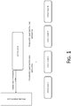
- FIG. 1 shows a schematic diagram of a working process of a central node and service nodes in a distributed system.
- the central node of the system may manage and control the service nodes.
- the service nodes will report their survival state information to the central node periodically.
- the central node confirms survival states of the service nodes according to the survival state information and performs a failure processing procedure if a failed service node is found.
- the central node cannot receive the survival state information reported by the service nodes due to a network delay or cannot process the survival state information in time due to an excessively high system resource load. All these situations may result in problems such as loss of the survival state information of the service nodes or invalidation of the next update time. In such cases, the central node may incorrectly determine the survival state of the service node.
- example embodiments of the present application are proposed to provide a method for processing nodes in a distributed system and a corresponding apparatus for processing nodes in a distributed system that solve or at least partially solve the foregoing problems.
- an example embodiment of the present application discloses a method for processing nodes in a distributed system, wherein the nodes include service nodes and a central node, and the method includes:
- the distributed system includes a state information table
- the step of acquiring survival state information of the service nodes includes:
- the survival state information includes a next update time of the service node
- the current system information includes a current system time of the central node
- the step of determining, by using the survival state information and the current system information, whether there is an abnormality of the service node includes:
- the step of determining, by using the next update time and the current system time, whether there is an abnormality of the service node includes:
- the central state information includes network busyness status data and/or system resource usage status data
- the step of processing the abnormal service node according to the central state information includes:
- the network busyness status data includes network throughput and a network packet loss rate
- the system resource usage status data includes an average load of the system
- the step of determining, by using the network busyness status data and/or the system resource usage status data, whether the central node is overloaded includes:
- the step of updating the survival state information of the abnormal service node in the state information table includes: extending the next update time of the abnormal service node in the state information table.
- the step of updating the survival state information of the abnormal service node in the state information table includes:
- the method further includes: treating the service node as a failed service node if there is no abnormality of the service node.
- the method further includes:
- An example embodiment of the present application further discloses an apparatus for processing nodes in a distributed system, wherein the nodes include service nodes and a central node, and the apparatus includes:
- the distributed system includes a state information table
- the survival state information acquisition module includes:
- the survival state information includes a next update time of the service node
- the current system information includes a current system time of the central node
- the service node abnormality determining module includes:
- the service node abnormality determining sub-module includes:
- the central state information includes network busyness status data and/or system resource usage status data
- the abnormal service node processing module includes:
- the network busyness status data includes network throughput and a network packet loss rate
- the system resource usage status data includes an average load of the system
- the central node state determining sub-module includes:
- the second state information table update sub-module includes: a next update time extension unit configured to extend the next update time of the abnormal service node in the state information table.
- the second state information table update sub-module includes:
- the apparatus further includes: a failed service node determining module configured to use the service node as a failed service node if there is no abnormality of the service node.
- a failed service node determining module configured to use the service node as a failed service node if there is no abnormality of the service node.
- the apparatus further includes:
- a central node confirms, according to survival state information reported by service nodes and current system information of the central node, whether there is an abnormality of the service node.
- the central node will further process the abnormal service node according to state information of the central node.
- the example embodiments of the present application may comprehensively consider a state of the central node to adaptively process an abnormal service node, thus reducing wrong determination of a service node state due to problems of the central node and reducing an error probability of the central node.
- the nodes may include service nodes and a central node.
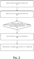
- the method may specifically include the following steps: Step 101. Survival state information of a service node is acquired.
- the service node refers to a node having a storage function or a service processing function in the distributed system, and is generally a device such as a server.
- the central node refers to a node having a service node coordination function in the distributed system, and is generally a device such as a controller. It should be noted that the example embodiment of the present application is not only applicable to the distributed system but is also applicable to a system in which a node may manage and control other nodes, which is not limited in the example embodiment of the present application.
- the distributed system may include a state information table.
- Step 101 may include the following sub-steps:
- the service node is coordinated by the central node. Therefore, the central node needs to know whether the service node works normally. It may be understood that as a device having storage and service functions, the service node needs to execute many tasks. Repeated task execution, system failures and other phenomena may occur in the task executing process because of too many tasks, too small remaining memory and other reasons. Therefore, the service node needs to report survival state information to inform the central node whether there is an abnormality or a failure. The central node will perform corresponding processing according to whether the service node has an abnormality or a failure.
- the central node stores a state information table.
- the table is used for storing survival state information that may reflect a survival state of the service node.
- the service node will periodically report its survival state information.
- the central node saves the survival state information in the state information table and updates a node state of the service node according to the survival state information.
- the central node may also send a request to the service node when the central node is idle, so as to request the service node to upload its survival state information, which is not limited in the example embodiment of the present application.
- Step 102 Current system information of the central node is acquired.
- Step 103 The central node determines, by using the survival state information and the current system information, whether there is an abnormality of the service node; and step 104 is performed if there is an abnormality of the service node.
- the survival state information may include a next update time of the service node
- the current system information may include a current system time of the central node
- step 103 may include the following sub-steps:
- the state information table stores a next update time of the service node.
- the next update time is reported by the service node to the central node according to a scheduling status of the service node and represents time for next survival state update. For example, the service node determines, according to its own scheduling status, that the next update time is February 24, 2016. If there is no abnormality of the service node, the service node should report the survival state information to the central node before February 24, 2016.
- the current system information may include a current system time at which the central node determines whether there is an abnormality of the service node. For example, the current system time may be February 25, 2016.
- next update time and current system time are merely used as examples.
- the time unit of the next update time and the current system time may be accurate to hour, minute and second, or rough to month and year, which is not limited in the example embodiment of the present application.
- the central node When the preset time arrives, the central node starts to detect whether there is an abnormality of the service node. Specifically, the central node starts to acquire its current system time, traverses next update times in the state information table, and compares each next update time with the current system time, so as to determine whether there is an abnormal service node among the service nodes.
- a cycle for traversing the state information table may be set to a fixed cycle, for example, 30 seconds, 1 minute, 10 minutes, 20 minutes, or the like; time for traversing may also be determined based on a service requirement.
- sub-step S22 may include the following sub-steps:
- Whether there is an abnormality of the service node may be determined by determining whether the next update time of the service node is less than the current system time of the central node. It may be understood that the next update time is time when the service node reports next survival state information. Therefore, if the next update time is less than the current system time, it indicates that due report time of the service node has passed, and it may be determined that there is an abnormality of the service node. If the next update time is greater than or equal to the current system time, it indicates that the due report time of the service node has not passed yet, and it may be determined that there is no abnormality of the service node.
- Step 104 Central state information of the central node is acquired.
- Step 105 The abnormal service node is processed according to the central state information.
- the state of the central node may also affect the determination of the service node abnormality. Therefore, the abnormal service node may be further processed with reference to the central state information of the central node.
- the central node confirms whether there is an abnormality of the service node according to the survival state information reported by the service node and the current system information of the central node.
- the central node will further process the abnormal service node according to the central state information of the central node.
- the example embodiment of the present application may comprehensively consider a state of the central node to adaptively process an abnormal service node, thus reducing wrong determination of a service node state due to problems of the central node and reducing an error probability of the central node.
- the nodes may include service nodes and a central node.
- the method specifically may include the following steps:
- the network busyness status data may be embodied as network throughput and a network packet loss rate.
- the system resource usage status data may be embodied as an average load of the system.
- the network throughput is referred to as throughput for short, and refers to the amount of data that is transmitted successfully through a network (or a channel or node) at any given moment.
- the throughput depends on a current available bandwidth of the network of the central node, and is limited by the network bandwidth.
- the throughput is usually an important indicator for a network test performed in actual network engineering, and for example, may be used for measuring performance of a network device.
- the network packet loss rate refers to a ratio of the amount of lost data to the amount of sent data.
- the packet loss rate is correlated to network load, data length, data sending frequency, and so on.
- the average load of the system refers to an average quantity of processes in queues run by the central node in a particular time interval.
- step 205 may include the following sub-steps:
- a formula for calculating the network busyness status of the central node is as follows: network throughput ⁇ bandwidth, or network packet loss rate > N%; wherein a value range of N is: 1-100.
- system resource usage status system average load value > N; wherein N is an integer, and generally, N > 1.
- the determination is made based on the network busyness status data and the system resource usage status data of the central node. If some or all of the data reach some critical values, it indicates that the central node is overloaded. In this case, a service node that is previously determined as abnormal by the central node is not necessarily a failed service node. Then, the next update time of the service node needs to be extended. If no data reaches the critical values, it indicates that the load of the central node is normal. In this case, the service node that is previously determined as abnormal by the central node should be a failed service node. As such, by taking the state of the central node into consideration, wrong determination about the service node due to problems of the central node may be reduced.
- Step 206 The survival state information of the abnormal service node in the state information table is updated.
- step 206 may include the following sub-steps: Sub-step S41.
- the next update time of the abnormal service node in the state information table is extended.
- the central node determines, with reference to the network busyness status and the system resource usage status of the central node, whether there is a failure among the service nodes. If the network is very busy or the system resources are very busy, the failure determination made by the central node for the service nodes is less credible. For example, update of survival states of the service nodes in the survival state information table may fail due to busyness of resources. In this case, the determination made by the central node may be not accepted, and processing of the central node is determined as failed. Meanwhile, in the state information table, the next update time of the service node that is previously determined as abnormal is extended correspondingly.
- step 206 may include the following sub-steps:
- the central node may automatically extend the next update time of the service node according to the state of the central node, or proactively initiates a state update request to the service node to extend the next update time of the service node, thus reducing wrong determination of the service node state due to problems of the central node.
- the central node may send an update request to the service node. After receiving the request, the service node reports a new next update time according to a task scheduling status of the service node. The central node updates the state information table by using the new next update time to extend the next update time of the service node.
- Step 207 The service node is used as a failed service node.
- the method further includes:
- related information such as a registration table
- other service nodes in the distributed system may be notified of the related information of the failed service node, such as an IP address of the failed service node. After receiving the notification, the service node may locally clear the related information of the failed service node.
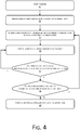
- FIG. 4 shows a schematic diagram of a working process of a central node and service nodes in a distributed system according to the present application
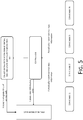
- FIG. 5 shows a schematic diagram of a working principle of a central node and service nodes in a distributed system. Specific steps are shown as follows:
- the central node determines, with reference to its own state, whether there is an abnormality of the service node, thus reducing wrong determination caused by that the node state information table is not updated due to the network congestion or system resource problem of the central node, and reducing an error probability of the central node.
- a survival state information acquisition module 301 is configured to acquire survival state information of the service node.
- the distributed system includes a state information table, and the survival state information acquisition module 301 may include the following sub-modules:
- a current system information acquisition module 302 is configured to acquire current system information of the central node.
- a service node abnormality determining module 303 is configured to determine, by using the survival state information and the current system information, whether there is an abnormality of the service node; and call a central state information acquisition module if there is an abnormality of the service node.
- the survival state information includes a next update time of the service node
- the current system information includes a current system time of the central node
- the service node abnormality determining module 303 may include the following sub-modules:
- the service node abnormality determining sub-module includes:
- a central state information acquisition module 304 is configured to acquire the central state information of the central node.
- An abnormal service node processing module 305 is configured to process the abnormal service node according to the central state information.
- the central state information includes network busyness status data and/or system resource usage status data
- the abnormal service node processing module 305 includes:
- the network busyness status data includes network throughput
- the system resource usage status data includes an average load of the system
- the central node state determining sub-module includes:
- the second state information table update sub-module includes: a next update time extension unit configured to extend the next update time of the abnormal service node in the state information table.
- the second state information table update sub-module includes:
- the apparatus further includes: a failed service node determining module configured to use the service node as a failed service node when there is no abnormality of the service node.
- the apparatus further includes:
- the apparatus example embodiment is basically similar to the method example embodiment, and therefore is described in a relatively simple manner. For related parts, reference may be made to the partial description of the method example embodiment.
- the example embodiment of the present application may be provided as a method, an apparatus, or a computer program product. Therefore, the example embodiment of the present application may be implemented as a complete hardware example embodiment, a complete software example embodiment, or an example embodiment combining software and hardware. Moreover, the example embodiment of the present application may be in the form of a computer program product implemented on one or more computer usable storage media (including, but not limited to, a magnetic disk memory, a CD-ROM, an optical memory, and the like) including computer usable program codes.
- a computer usable storage media including, but not limited to, a magnetic disk memory, a CD-ROM, an optical memory, and the like
- the computer device includes one or more processors (CPU), an input/output interface, a network interface, and a memory.
- the memory may include a volatile memory, a random access memory (RAM) and/or a non-volatile memory or the like in a computer readable medium, for example, a read-only memory (ROM) or a flash RAM.
- RAM random access memory
- ROM read-only memory
- flash RAM flash RAM
- the memory is an example of the computer readable medium.
- the computer readable medium includes non-volatile and volatile media as well as movable and non-movable media, and may implement information storage by means of any method or technology.
- Information may be a computer readable instruction, a data structure, and a module of a program or other data.
- a storage medium of a computer includes, for example, but is not limited to, a phase change memory (PRAM), a static random access memory (SRAM), a dynamic random access memory (DRAM), other types of RAMs, a ROM, an electrically erasable programmable read-only memory (EEPROM), a flash memory or other memory technologies, a compact disk read-only memory (CD-ROM), a digital versatile disc (DVD) or other optical storages, a cassette tape, a magnetic tape/magnetic disk storage or other magnetic storage devices, or any other non-transmission media, and may be used to store information accessible to the computing device.
- the computer readable medium does not include transitory media, such as modulated data signals and carriers.
- the computer-readable instructions may be provided to a general-purpose computer, a special-purpose computer, an embedded processor or a processor of another programmable data processing terminal device to generate a machine, such that the computer or the processor of another programmable data processing terminal device executes an instruction to generate an apparatus configured to implement functions designated in one or more processes in a flowchart and/or one or more blocks in a block diagram.
- the computer-readable instructions may also be stored in a computer readable memory that may guide the computer or another programmable data processing terminal device to work in a specific manner, such that the instruction stored in the computer readable memory generates an article of manufacture including an instruction apparatus, and the instruction apparatus implements functions designated by one or more processes in a flowchart and/or one or more blocks in a block diagram.
- the computer-readable instructions may also be loaded into a computer or another programmable data processing terminal device, such that a series of operation steps are executed on the computer or another programmable terminal device to generate computer-implemented processing. Therefore, the instruction executed in the computer or another programmable terminal device provides steps for implementing functions designated in one or more processes in a flowchart and/or one or more blocks in a block diagram.
Landscapes
- Engineering & Computer Science (AREA)
- Computer Networks & Wireless Communication (AREA)
- Signal Processing (AREA)
- Environmental & Geological Engineering (AREA)
- General Engineering & Computer Science (AREA)
- Cardiology (AREA)
- General Health & Medical Sciences (AREA)
- Health & Medical Sciences (AREA)
- Theoretical Computer Science (AREA)
- Computer Hardware Design (AREA)
- Quality & Reliability (AREA)
- Physics & Mathematics (AREA)
- General Physics & Mathematics (AREA)
- Debugging And Monitoring (AREA)
- Computer And Data Communications (AREA)
- Hardware Redundancy (AREA)
Abstract
Description
- The present application relates to the field of data processing technologies, and, more particularly, to a method for processing nodes in a distributed system and an apparatus for processing nodes in a distributed system.
- A distributed system is a system including one or more independent nodes that are geographically and physically scattered. The nodes include service nodes and a central node. The central node may coordinate the service nodes. The nodes may be connected together to share resources. The distributed system is equivalent to a unified whole.
- In a running process of the distributed system, it is a very important link to monitor survival states of the service nodes. A common approach is that each service node in the distributed system sends survival state information to the central node at an interval of a preset cycle. After receiving the survival state information, the central node updates its state information table by using the survival state information. The state information table records the latest update time and a next update time of each service node. In order to monitor the survival states of the service nodes, the central node will view the state information table from time to time to confirm the survival states of the service nodes. If the central node finds that the next update time of a service node is less than the current system time, the service node is determined to be in an abnormal state.
-
FIG. 1 shows a schematic diagram of a working process of a central node and service nodes in a distributed system. The central node of the system may manage and control the service nodes. The service nodes will report their survival state information to the central node periodically. The central node confirms survival states of the service nodes according to the survival state information and performs a failure processing procedure if a failed service node is found. However, it is possible that the central node cannot receive the survival state information reported by the service nodes due to a network delay or cannot process the survival state information in time due to an excessively high system resource load. All these situations may result in problems such as loss of the survival state information of the service nodes or invalidation of the next update time. In such cases, the central node may incorrectly determine the survival state of the service node. - In view of the foregoing problems, example embodiments of the present application are proposed to provide a method for processing nodes in a distributed system and a corresponding apparatus for processing nodes in a distributed system that solve or at least partially solve the foregoing problems.
- In order to solve the foregoing problems, an example embodiment of the present application discloses a method for processing nodes in a distributed system, wherein the nodes include service nodes and a central node, and the method includes:
- acquiring survival state information of a service node;
- acquiring current system information of the central node;
- determining, by using the survival state information and the current system information, whether there is an abnormality of the service node;
- acquiring central state information of the central node if there is an abnormality of the service node; and
- processing the abnormal service node according to the central state information.
- Preferably, the distributed system includes a state information table, and the step of acquiring survival state information of the service nodes includes:
- receiving the survival state information uploaded by the service node; and
- updating the state information table by using the survival state information of the service node.
- Preferably, the survival state information includes a next update time of the service node, the current system information includes a current system time of the central node, and the step of determining, by using the survival state information and the current system information, whether there is an abnormality of the service node includes:
- traversing to find the next update time of the service node in the state information table when a preset time arrives; and
- determining, by using the next update time and the current system time, whether there is an abnormality of the service node.
- Preferably, the step of determining, by using the next update time and the current system time, whether there is an abnormality of the service node includes:
- determining whether the next update time is less than the current system time;
- if yes, determining that there is an abnormality of the service node; and
- if no, determining that there is no abnormality of the service node.
- Preferably, the central state information includes network busyness status data and/or system resource usage status data, and the step of processing the abnormal service node according to the central state information includes:
- determining, by using the network busyness status data and/or the system resource usage status data, whether the central node is overloaded; and
- if yes, updating the survival state information of the abnormal service node in the state information table.
- Preferably, the network busyness status data includes network throughput and a network packet loss rate, the system resource usage status data includes an average load of the system, and the step of determining, by using the network busyness status data and/or the system resource usage status data, whether the central node is overloaded includes:
- determining whether the network throughput is greater than or equal to a network bandwidth;
- determining whether the network packet loss rate is greater than a preset packet loss rate;
- determining whether the average load of the system is greater than a preset load threshold; and
- determining that the central node is overloaded if the network throughput is greater than or equal to the network bandwidth, and/or the network packet loss rate is greater than the preset packet loss rate, and/or the average load of the system is greater than the preset load threshold.
- Preferably, the step of updating the survival state information of the abnormal service node in the state information table includes:
extending the next update time of the abnormal service node in the state information table. - Preferably, the step of updating the survival state information of the abnormal service node in the state information table includes:
- sending an update request to the service node;
- receiving new survival state information that is uploaded by the service node with respect to the update request, the new survival state information including a new next update time; and
- updating the next update time of the abnormal service node in the state information table by using the new next update time.
- Preferably, the method further includes:
treating the service node as a failed service node if there is no abnormality of the service node. - Preferably, after the step of treating the service node as a failed service node, the method further includes:
- deleting the failed service node from the central node; and
- notifying other service nodes in the distributed system of the failed service node.
- An example embodiment of the present application further discloses an apparatus for processing nodes in a distributed system, wherein the nodes include service nodes and a central node, and the apparatus includes:
- a survival state information acquisition module configured to acquire survival state information of a service node;
- a current system information acquisition module configured to acquire current system information of the central node;
- a service node abnormality determining module configured to determine, by using the survival state information and the current system information, whether there is an abnormality of the service node; and call a central state information acquisition module if there is an abnormality of the service node;
- the central state information acquisition module configured to acquire central state information of the central node; and
- an abnormal service node processing module configured to process the abnormal service node according to the central state information.
- Preferably, the distributed system includes a state information table, and the survival state information acquisition module includes:
- a survival state information receiving sub-module configured to receive the survival state information uploaded by the service nodes; and
- a first state information table update sub-module configured to update the state information table by using the survival state information of the service nodes.
- Preferably, the survival state information includes a next update time of the service node, the current system information includes a current system time of the central node, and the service node abnormality determining module includes:
- a state information table traversing sub-module configured to traverse next update time in the state information table when a preset time arrives; and
- a service node abnormality determining sub-module configured to determine, by using the next update time and the current system time, whether there is an abnormality of the service node.
- Preferably, the service node abnormality determining sub-module includes:
- a time determination unit configured to determine whether the next update time is less than the current system time; if yes, call a first determining unit; and if no, call a second determining unit;
- the first determining unit configured to determine that there is an abnormality of the service node; and
- the second determining unit configured to determine that there is no abnormality of the service node.
- Preferably, the central state information includes network busyness status data and/or system resource usage status data, and the abnormal service node processing module includes:
- a central node state determining sub-module configured to determine, by using the network busyness status data and/or the system resource usage status data, whether the central node is overloaded; and if yes, call a second state information table update sub-module; and
- the second state information table update sub-module configured to update the survival state information of the abnormal service node in the state information table.
- Preferably, the network busyness status data includes network throughput and a network packet loss rate, the system resource usage status data includes an average load of the system, and the central node state determining sub-module includes:
- a first network busyness status determination unit configured to determine whether the network throughput is greater than or equal to a network bandwidth;
- a second network busyness status determination unit configured to determine whether the network packet loss rate is greater than a preset packet loss rate;
- a system resource usage status determination unit configured to determine whether the average load of the system is greater than a preset load threshold; and
- a central node load determining unit configured to determine that the central node is overloaded when the network throughput is greater than or equal to the network bandwidth, and/or the network packet loss rate is greater than the preset packet loss rate, and/or the average load of the system is greater than the preset load threshold.
- Preferably, the second state information table update sub-module includes:
a next update time extension unit configured to extend the next update time of the abnormal service node in the state information table. - Preferably, the second state information table update sub-module includes:
- an update request sending unit configured to send an update request to the service node;
- a next update time receiving unit configured to receive new survival state information that is uploaded by the service node with respect to the update request, the new survival state information comprising a new next update time; and
- a next update time updating unit configured to update the next update time of the abnormal service node in the state information table by using the new next update time.
- Preferably, the apparatus further includes:
a failed service node determining module configured to use the service node as a failed service node if there is no abnormality of the service node. - Preferably, the apparatus further includes:
- a failed service node deletion module configured to delete the failed service node from the central node; and
- a failed service node notification module configured to notify other service nodes in the distributed system of the failed service node.
- The example embodiments of the present application include the following advantages:
In a distributed system in the example embodiments of the present application, a central node confirms, according to survival state information reported by service nodes and current system information of the central node, whether there is an abnormality of the service node. When there is an abnormality of the service node, the central node will further process the abnormal service node according to state information of the central node. The example embodiments of the present application may comprehensively consider a state of the central node to adaptively process an abnormal service node, thus reducing wrong determination of a service node state due to problems of the central node and reducing an error probability of the central node. -
-
FIG. 1 is a schematic diagram of a working process of a central node and service nodes in a distributed system; -
FIG. 2 is a flowchart of steps inExample embodiment 1 of a method for processing nodes in a distributed system according to the present application; -
FIG. 3 is a flowchart of steps inExample embodiment 2 of a method for processing nodes in a distributed system according to the present application; -
FIG. 4 is a flowchart of working steps of a central node and service nodes in a distributed system according to the present application; -
FIG. 5 is a schematic diagram of a working principle of a central node and service nodes in a distributed system according to the present application; and -
FIG. 6 is a structural block diagram of an example embodiment of an apparatus for processing nodes in a distributed system according to the present application. - In order to make the foregoing objectives, features and advantages of the present application easier to understand, the present application is described in further detail below with reference to the accompanying drawings and specific implementation manners.
- Referring to
FIG. 2 , a flowchart of steps inExample embodiment 1 of a method for processing nodes in a distributed system according to the present application is shown. The nodes may include service nodes and a central node. The method may specifically include the following steps:
Step 101. Survival state information of a service node is acquired. - In a specific implementation, the service node refers to a node having a storage function or a service processing function in the distributed system, and is generally a device such as a server. The central node refers to a node having a service node coordination function in the distributed system, and is generally a device such as a controller. It should be noted that the example embodiment of the present application is not only applicable to the distributed system but is also applicable to a system in which a node may manage and control other nodes, which is not limited in the example embodiment of the present application.
- In a preferred example embodiment of the present application, the distributed system may include a state information table. Step 101 may include the following sub-steps:
- Sub-step S11. The survival state information uploaded by the service nodes is received.
- Sub-step S12. The state information table is updated by using the survival state information of the service nodes.
- In a specific implementation, the service node is coordinated by the central node. Therefore, the central node needs to know whether the service node works normally. It may be understood that as a device having storage and service functions, the service node needs to execute many tasks. Repeated task execution, system failures and other phenomena may occur in the task executing process because of too many tasks, too small remaining memory and other reasons. Therefore, the service node needs to report survival state information to inform the central node whether there is an abnormality or a failure. The central node will perform corresponding processing according to whether the service node has an abnormality or a failure.
- In an example of the present application, the central node stores a state information table. The table is used for storing survival state information that may reflect a survival state of the service node. The service node will periodically report its survival state information. The central node saves the survival state information in the state information table and updates a node state of the service node according to the survival state information. Certainly, the central node may also send a request to the service node when the central node is idle, so as to request the service node to upload its survival state information, which is not limited in the example embodiment of the present application.
-
Step 102. Current system information of the central node is acquired. -
Step 103. The central node determines, by using the survival state information and the current system information, whether there is an abnormality of the service node; and step 104 is performed if there is an abnormality of the service node. - In a preferred example embodiment of the present application, the survival state information may include a next update time of the service node, the current system information may include a current system time of the central node, and step 103 may include the following sub-steps:
- Sub-step S21. Next update times in the state information table are traversed when a preset time arrives.
- Sub-step S22. The central node determines, by using the next update times and the current system time, whether there is an abnormal service node among the service nodes.
- In an example of the present application, the state information table stores a next update time of the service node. The next update time is reported by the service node to the central node according to a scheduling status of the service node and represents time for next survival state update. For example, the service node determines, according to its own scheduling status, that the next update time is February 24, 2016. If there is no abnormality of the service node, the service node should report the survival state information to the central node before February 24, 2016. In addition, the current system information may include a current system time at which the central node determines whether there is an abnormality of the service node. For example, the current system time may be February 25, 2016.
- It should be noted that the foregoing next update time and current system time are merely used as examples. In a specific application, the time unit of the next update time and the current system time may be accurate to hour, minute and second, or rough to month and year, which is not limited in the example embodiment of the present application.
- When the preset time arrives, the central node starts to detect whether there is an abnormality of the service node. Specifically, the central node starts to acquire its current system time, traverses next update times in the state information table, and compares each next update time with the current system time, so as to determine whether there is an abnormal service node among the service nodes. A cycle for traversing the state information table may be set to a fixed cycle, for example, 30 seconds, 1 minute, 10 minutes, 20 minutes, or the like; time for traversing may also be determined based on a service requirement.
- In a preferred example embodiment of the present application, sub-step S22 may include the following sub-steps:
- Sub-step S22-11. determining whether the next update time is less than the current system time of a respective service node; if yes, sub-step S22-12 is performed; if no, sub-step S22-13 is performed.
- Sub-step S22-12. determining that there is an abnormality of the respective service node.
- Sub-step S22-13. determining that there is no abnormality of the respective service node.
- Whether there is an abnormality of the service node may be determined by determining whether the next update time of the service node is less than the current system time of the central node. It may be understood that the next update time is time when the service node reports next survival state information. Therefore, if the next update time is less than the current system time, it indicates that due report time of the service node has passed, and it may be determined that there is an abnormality of the service node. If the next update time is greater than or equal to the current system time, it indicates that the due report time of the service node has not passed yet, and it may be determined that there is no abnormality of the service node.
-
Step 104. Central state information of the central node is acquired. -
Step 105. The abnormal service node is processed according to the central state information. - In the determination of an abnormal service node in the example embodiment of the present application, the state of the central node may also affect the determination of the service node abnormality. Therefore, the abnormal service node may be further processed with reference to the central state information of the central node.
- In the distributed system in the example embodiment of the present application, the central node confirms whether there is an abnormality of the service node according to the survival state information reported by the service node and the current system information of the central node. When determining that there is an abnormality of the service node, the central node will further process the abnormal service node according to the central state information of the central node.
- The example embodiment of the present application may comprehensively consider a state of the central node to adaptively process an abnormal service node, thus reducing wrong determination of a service node state due to problems of the central node and reducing an error probability of the central node.
- Referring to
FIG. 3 , a flowchart of steps inExample embodiment 2 of a method for processing nodes in a distributed system according to the present application is shown. The nodes may include service nodes and a central node. The method specifically may include the following steps: -
Step 201. Survival state information of the service nodes is acquired. -
Step 202. Current system information of the central node is acquired. -
Step 203. The central node determines, by using the survival state information and the current system information, whether there is an abnormality of the service node; if there is an abnormality of the service node, step 204 is performed; if there is no abnormality of the service node,step 207 is performed. - Step 204. Central state information of the central node is acquired, wherein the central state information may include network busyness status data and/or system resource usage status data.
-
Step 205. The central node determines, by using the network busyness status data and/or the system resource usage status data, whether the central node is overloaded; and if yes, step 206 is performed. - In a specific application example of the present application, the network busyness status data may be embodied as network throughput and a network packet loss rate. The system resource usage status data may be embodied as an average load of the system.
- Specifically, the network throughput is referred to as throughput for short, and refers to the amount of data that is transmitted successfully through a network (or a channel or node) at any given moment. The throughput depends on a current available bandwidth of the network of the central node, and is limited by the network bandwidth. The throughput is usually an important indicator for a network test performed in actual network engineering, and for example, may be used for measuring performance of a network device. The network packet loss rate refers to a ratio of the amount of lost data to the amount of sent data. The packet loss rate is correlated to network load, data length, data sending frequency, and so on. The average load of the system refers to an average quantity of processes in queues run by the central node in a particular time interval.
- In a preferred example embodiment of the present application,
step 205 may include the following sub-steps: - Sub-step S31. determining whether the network throughput is greater than or equal to a network bandwidth.
- Sub-step S32. determining whether the network packet loss rate is greater than a preset packet loss rate.
- Sub-step S33. determining whether the average load of the system is greater than a preset load threshold; sub-step S34 is performed if the network throughput is greater than or equal to the network bandwidth, and/or the network packet loss rate is greater than the preset packet loss rate, and/or the average load of the system is greater than the preset load threshold.
- Sub-step S34. determining that the central node is overloaded.
- In a specific application example of the present application, a formula for calculating the network busyness status of the central node is as follows:

- A formula for calculating the system resource usage status of the central node is as follows:

- In the example embodiment of the present application, the determination is made based on the network busyness status data and the system resource usage status data of the central node. If some or all of the data reach some critical values, it indicates that the central node is overloaded. In this case, a service node that is previously determined as abnormal by the central node is not necessarily a failed service node. Then, the next update time of the service node needs to be extended. If no data reaches the critical values, it indicates that the load of the central node is normal. In this case, the service node that is previously determined as abnormal by the central node should be a failed service node. As such, by taking the state of the central node into consideration, wrong determination about the service node due to problems of the central node may be reduced.
-
Step 206. The survival state information of the abnormal service node in the state information table is updated. - In a preferred example embodiment of the present application,
step 206 may include the following sub-steps:
Sub-step S41. The next update time of the abnormal service node in the state information table is extended. - In the example embodiment of the present application, the central node determines, with reference to the network busyness status and the system resource usage status of the central node, whether there is a failure among the service nodes. If the network is very busy or the system resources are very busy, the failure determination made by the central node for the service nodes is less credible. For example, update of survival states of the service nodes in the survival state information table may fail due to busyness of resources. In this case, the determination made by the central node may be not accepted, and processing of the central node is determined as failed. Meanwhile, in the state information table, the next update time of the service node that is previously determined as abnormal is extended correspondingly.
- In a preferred example embodiment of the present application,
step 206 may include the following sub-steps: - Sub-step S51. An update request is sent to the service node.
- Sub-step S52. New survival state information that is uploaded by the service node with respect to the update request is received, the new survival state information including a new next update time.
- Sub-step S53. The next update time of the abnormal service node in the state information table is updated by using the new next update time.
- The central node may automatically extend the next update time of the service node according to the state of the central node, or proactively initiates a state update request to the service node to extend the next update time of the service node, thus reducing wrong determination of the service node state due to problems of the central node.
- In an example of the present application, for the next update time of a service node that is previously determined as abnormal, the central node may send an update request to the service node. After receiving the request, the service node reports a new next update time according to a task scheduling status of the service node. The central node updates the state information table by using the new next update time to extend the next update time of the service node.
-
Step 207. The service node is used as a failed service node. - In a preferred example embodiment of the present application, after the step of treating the service node as a failed service node, the method further includes:
- deleting the failed service node from the central node; and
- notifying other service nodes in the distributed system of the failed service node.
- In the example embodiment of the present application, if the service node is determined as failed, related information, such as a registration table, of the failed service node may be deleted from the central node. In addition, other service nodes in the distributed system may be notified of the related information of the failed service node, such as an IP address of the failed service node. After receiving the notification, the service node may locally clear the related information of the failed service node.
- To help those skilled in the art better understand the example embodiment of the present application, a monitoring and processing manner of node states in a distributed system is described below by using a specific example.
FIG. 4 shows a schematic diagram of a working process of a central node and service nodes in a distributed system according to the present application, andFIG. 5 shows a schematic diagram of a working principle of a central node and service nodes in a distributed system. Specific steps are shown as follows: - S1. A program is started.
- S2. The service nodes report survival state information to the central node.
- S3. The central node updates a state information table according to the survival state information of the service nodes, update content including: the latest update time and a next update time.
- S4. The central node scans the survival state information table.
- S5. The central node determines whether a next update time of a service node is less than a current system time; if yes, S6 is performed; if no, S4 is performed again to continue scanning the survival state information table.
- S6. The central node determines a network busyness status and a system resource usage status of the central node; if the network is very busy or the system resources are busy, the next update time of the service node in the survival state information table is extended.
- S7. Failure process processing of the service node is started.
- In the example embodiment of the present application, the central node determines, with reference to its own state, whether there is an abnormality of the service node, thus reducing wrong determination caused by that the node state information table is not updated due to the network congestion or system resource problem of the central node, and reducing an error probability of the central node.
- It should be noted that for ease of description, the foregoing method example embodiments are all described as a series of action combinations. However, those skilled in the art should understand that the example embodiments of the present application are not limited to the described sequence of the actions, because some steps may be performed in another sequence or at the same time according to the example embodiments of the present application. In addition, those skilled in the art should also understand that the example embodiments described in this specification all belong to preferred example embodiments, and the involved actions are not necessarily mandatory to the example embodiments of the present application.
- Referring to
FIG. 6 , a structural block diagram of an example embodiment of an apparatus for processing nodes in a distributed system according to the present application is shown. The nodes include service nodes and a central node. The apparatus specifically may include the following modules:
A survival state information acquisition module 301 is configured to acquire survival state information of the service node. - In a preferred example embodiment of the present application, the distributed system includes a state information table, and the survival state information acquisition module 301 may include the following sub-modules:
- a survival state information receiving sub-module configured to receive the survival state information uploaded by the service nodes; and
- a first state information table update sub-module configured to update the state information table by using the survival state information of the service nodes.
- A current system
information acquisition module 302 is configured to acquire current system information of the central node. - A service node
abnormality determining module 303 is configured to determine, by using the survival state information and the current system information, whether there is an abnormality of the service node; and call a central state information acquisition module if there is an abnormality of the service node. - In a preferred example embodiment of the present application, the survival state information includes a next update time of the service node, the current system information includes a current system time of the central node, and the service node
abnormality determining module 303 may include the following sub-modules: - a state information table traversing sub-module configured to traverse next update times in the state information table when a preset time arrives; and
- a service node abnormality determining sub-module configured to determine whether there is an abnormality of the service node by using the next update times and the current system time.
- In a preferred example embodiment of the present application, the service node abnormality determining sub-module includes:
- a time determination unit configured to determine whether the next update time is less than the current system time; if yes, call a first determining unit; and if no, call a second determining unit;
- the first determining unit configured to determine that there is an abnormality of the service node; and
- the second determining unit configured to determine that there is no abnormality of the service node.
- A central state
information acquisition module 304 is configured to acquire the central state information of the central node. - An abnormal service
node processing module 305 is configured to process the abnormal service node according to the central state information. - In a preferred example embodiment of the present application, the central state information includes network busyness status data and/or system resource usage status data, and the abnormal service
node processing module 305 includes: - a central node state determining sub-module configured to determine, by using the network busyness status data and/or the system resource usage status data, whether the central node is overloaded; and if yes, call a second state information table update sub-module; and
- the second state information table update sub-module configured to update the survival state information of the abnormal service node in the state information table.
- In a preferred example embodiment of the present application, the network busyness status data includes network throughput, the system resource usage status data includes an average load of the system, and the central node state determining sub-module includes:
- a first network busyness status determination unit configured to determine whether the network throughput is greater than or equal to a network bandwidth;
- a second network busyness status determination unit configured to determine whether the network packet loss rate is greater than a preset packet loss rate;
- a system resource usage status determination unit configured to determine whether the average load of the system is greater than a preset load threshold; and
- a central node load determining unit configured to determine that the central node is overloaded when the network throughput is greater than or equal to the network bandwidth, and/or the network packet loss rate is greater than the preset packet loss rate, and/or the average load of the system is greater than the preset load threshold.
- In a preferred example embodiment of the present application, the second state information table update sub-module includes:
a next update time extension unit configured to extend the next update time of the abnormal service node in the state information table. - In another preferred example embodiment of the present application, the second state information table update sub-module includes:
- an update request sending unit configured to send an update request to the service node;
- a next update time receiving unit configured to receive new survival state information that is uploaded by the service node with respect to the update request, the new survival state information comprising a new next update time; and
- a next update time updating unit configured to update the next update time of the abnormal service node in the state information table by using the new next update time.
- In a preferred example embodiment of the present application, the apparatus further includes:
a failed service node determining module configured to use the service node as a failed service node when there is no abnormality of the service node. - In a preferred example embodiment of the present application, the apparatus further includes:
- a failed service node deletion module configured to delete the failed service node from the central node; and
- a failed service node notification module configured to notify other service nodes in the distributed system of the failed service node.
- The apparatus example embodiment is basically similar to the method example embodiment, and therefore is described in a relatively simple manner. For related parts, reference may be made to the partial description of the method example embodiment.
- The example embodiments in the specification are described progressively. Each example embodiment focuses on a difference from other example embodiments. For identical or similar parts of the example embodiments, reference may be made to each other.
- Those skilled in the art should understand that the example embodiment of the present application may be provided as a method, an apparatus, or a computer program product. Therefore, the example embodiment of the present application may be implemented as a complete hardware example embodiment, a complete software example embodiment, or an example embodiment combining software and hardware. Moreover, the example embodiment of the present application may be in the form of a computer program product implemented on one or more computer usable storage media (including, but not limited to, a magnetic disk memory, a CD-ROM, an optical memory, and the like) including computer usable program codes.
- In a typical configuration, the computer device includes one or more processors (CPU), an input/output interface, a network interface, and a memory. The memory may include a volatile memory, a random access memory (RAM) and/or a non-volatile memory or the like in a computer readable medium, for example, a read-only memory (ROM) or a flash RAM. The memory is an example of the computer readable medium. The computer readable medium includes non-volatile and volatile media as well as movable and non-movable media, and may implement information storage by means of any method or technology. Information may be a computer readable instruction, a data structure, and a module of a program or other data. A storage medium of a computer includes, for example, but is not limited to, a phase change memory (PRAM), a static random access memory (SRAM), a dynamic random access memory (DRAM), other types of RAMs, a ROM, an electrically erasable programmable read-only memory (EEPROM), a flash memory or other memory technologies, a compact disk read-only memory (CD-ROM), a digital versatile disc (DVD) or other optical storages, a cassette tape, a magnetic tape/magnetic disk storage or other magnetic storage devices, or any other non-transmission media, and may be used to store information accessible to the computing device. According to the definition in this text, the computer readable medium does not include transitory media, such as modulated data signals and carriers.
- The example embodiments of present application are described with reference to flowcharts and/or block diagrams according to the method, the terminal device (system), and the computer program product of the example embodiments of the present application. It should be understood that a computer program instruction may be used to implement each process and/or block in the flowcharts and/or block diagrams and combinations of processes and/or blocks in the flowcharts and/or block diagrams. The computer-readable instructions may be provided to a general-purpose computer, a special-purpose computer, an embedded processor or a processor of another programmable data processing terminal device to generate a machine, such that the computer or the processor of another programmable data processing terminal device executes an instruction to generate an apparatus configured to implement functions designated in one or more processes in a flowchart and/or one or more blocks in a block diagram.
- The computer-readable instructions may also be stored in a computer readable memory that may guide the computer or another programmable data processing terminal device to work in a specific manner, such that the instruction stored in the computer readable memory generates an article of manufacture including an instruction apparatus, and the instruction apparatus implements functions designated by one or more processes in a flowchart and/or one or more blocks in a block diagram.
- The computer-readable instructions may also be loaded into a computer or another programmable data processing terminal device, such that a series of operation steps are executed on the computer or another programmable terminal device to generate computer-implemented processing. Therefore, the instruction executed in the computer or another programmable terminal device provides steps for implementing functions designated in one or more processes in a flowchart and/or one or more blocks in a block diagram.
- Although preferred example embodiments of the example embodiments of the present application have been described, those skilled in the art may make other changes and modifications to these example embodiments once knowing the basic inventive concept. Therefore, the appended claims are intended to be interpreted as including the preferred example embodiments and all changes and modifications falling into the scope of the example embodiments of the present application.
- Finally, it should be further noted that relational terms such as "first" and "second" in this text are only used for distinguishing one entity or operation from another entity or operation, but does not necessarily require or imply any such actual relations or sequences between these entities or operations. Moreover, the terms "include", "comprise" or other variations thereof are intended to cover a non-exclusive inclusion, so that a process, method, article or terminal device including a series of elements not only includes the elements, but also includes other elements not clearly listed, or further includes elements inherent to the process, method, article or terminal device. In the absence of more limitations, an element defined by "including a/an..." does not exclude that the process, method, article or terminal device including the element further has other identical elements.
- A method for processing nodes in a distributed system and an apparatus for processing nodes in a distributed system provided in the present application are described above in detail. Specific examples are used in the text to illustrate the principle and implementations of the present application, and the description of the example embodiments above is merely used to help understand the method of the present application and its core idea. Meanwhile, those of ordinary skill in the art may change the specific implementations and application ranges according to the idea of the present application. In conclusion, the content of the specification should not be construed as a limitation to the present application.
Claims (20)
- A method for processing nodes in a distributed system, wherein the nodes comprise a service node and a central node, and the method comprises:acquiring survival state information of the service node;acquiring current system information of the central node;determining, by using the survival state information and the current system information, whether there is an abnormality of the service node;acquiring central state information of the central node in response to determining that there is the abnormality of the service node; andprocessing the service node according to the central state information.
- The method of claim 1, wherein:the distributed system comprises a state information table; andthe acquiring the survival state information of the service node comprises:receiving the survival state information uploaded by the service node; andupdating the state information table by using the survival state information of the service node.
- The method of claim 1 or 2, wherein:the survival state information comprises a next update time of the service node;the current system information comprises a current system time of the central node; andthe determining, by using the survival state information and the current system information, whether there is an abnormality of the service node comprises:traversing to find the next update times of the service node in the state information table when a preset time arrives; anddetermining, by using the next update time and the current system time, whether there is the abnormality of the service node.
- The method of claim 3, wherein the determining, by using the next update times and the current system time, whether there is the abnormality of the service node comprises:
determining whether the next update time is less than the current system time; andin response to determining that the next update time is less than the current system time, determining that there is the abnormality of the service node; orin response to determining that the next update time is not less than the current system time, determining that there is no abnormality of the service node. - The method of claim 1 or 2, wherein:the central state information comprises network busyness status data and/or system resource usage status data; andthe processing the service node according to the central state information comprises:determining, by using the network busyness status data and/or the system resource usage status data, whether the central node is overloaded; andin response to determining that the central node is overloaded, updating the survival state information of the service node in the state information table.
- The method of claim 5, wherein:the network busyness status data comprises a network throughput and a network packet loss rate;the system resource usage status data comprises an average load of the system; andthe determining, by using the network busyness status data and/or the system resource usage status data, whether the central node is overloaded comprises:determining whether the network throughput is greater than or equal to a network bandwidth;determining whether the network packet loss rate is greater than a preset packet loss rate;determining whether the average load of the system is greater than a preset load threshold; anddetermining that the central node is overloaded in response to determining that the network throughput is greater than or equal to the network bandwidth, the network packet loss rate is greater than the preset packet loss rate, and/or the average load of the system is greater than the preset load threshold.
- The method of claim 5, wherein the updating the survival state information of the service node in the state information table comprises:
extending a next update time of the service node in the state information table. - The method of claim 5, wherein the updating the survival state information of the service node in the state information table comprises:sending an update request to the service node;receiving new survival state information that is uploaded by the service node with respect to the update request, the new survival state information comprising a new next update time; andupdating a next update time of the service node in the state information table by using the new next update time.
- The method of claim 1, further comprising:
treating the service node as a failed service node if there is no abnormality of the service node. - The method of claim 1, further comprising:after treating the service node as a failed service node,deleting the failed service node from the central node; andnotifying other service nodes in the distributed system of the failed service node.
- An apparatus for processing nodes in a distributed system, wherein the nodes comprise a service node and a central node, and the apparatus comprises:a survival state information acquisition module configured to acquire survival state information of the service node;a current system information acquisition module configured to acquire current system information of the central node;a service node abnormality determining module configured to determine, by using the survival state information and the current system information, whether there is an abnormality of the service node; and call a central state information acquisition module in response to determining that there is an abnormality of the service node;the central state information acquisition module configured to acquire central state information of the central node; andan abnormal service node processing module configured to process the service node that has abnormality according to the central state information.
- The apparatus of claim 11, wherein:the distributed system comprises a state information table; andthe survival state information acquisition module comprises:a survival state information receiving sub-module configured to receive the survival state information uploaded by the service nodes; anda first state information table update sub-module configured to update the state information table by using the survival state information of the service node.
- The apparatus of claim 11 or 12, wherein:the survival state information comprises a next update time of the service node;the current system information comprises a current system time of the central node; andthe service node abnormality determining module comprises:a state information table traversing sub-module configured to traverse to find the next update time of the service node in the state information table when a preset time arrives; anda service node abnormality determining sub-module configured to determine, by using the next update time and the current system time, whether there is the abnormality of the service node.
- The apparatus of claim 13, wherein the service node abnormality determining sub-module comprises:a time determination unit configured to determine whether the next update time is less than the current system time; in response to determining that the next update time is less than the current system time, call a first determining unit; or if in response to determining that the next update time is not less than the current system time, call a second determining unit;the first determining unit configured to determine that there is the abnormality of the service node; andthe second determining unit configured to determine that there is no abnormality of the service node.
- The apparatus of claim 11 or 12, wherein:the central state information comprises network busyness status data and/or system resource usage status data; andthe abnormal service node processing module comprises:a central node state determining sub-module configured to determine, by using the network busyness status data and/or the system resource usage status data, whether the central node is overloaded; and, in response to determining that the central node is overloaded, call a second state information table update sub-module; andthe second state information table update sub-module configured to update the survival state information of the abnormal service node in the state information table.
- The apparatus of claim 15, wherein:the network busyness status data comprises a network throughput and a network packet loss rate;the system resource usage status data comprises an average load of the system; andthe central node state determining sub-module comprises:a first network busyness status determination unit configured to determine whether the network throughput is greater than or equal to a network bandwidth;a second network busyness status determination unit configured to determine whether the network packet loss rate is greater than a preset packet loss rate;a system resource usage status determination unit configured to determine whether the average load of the system is greater than a preset load threshold; anda central node load determining unit configured to determine that the central node is overloaded when the network throughput is greater than or equal to the network bandwidth, the network packet loss rate is greater than the preset packet loss rate, and/or the average load of the system is greater than the preset load threshold.
- The apparatus of claim 15, wherein the second state information table update sub-module comprises:
a next update time extension unit configured to extend the next update time of the service node in the state information table. - The apparatus of claim 15, wherein the second state information table update sub-module comprises:an update request sending unit configured to send an update request to the service node;a next update time receiving unit configured to receive new survival state information that is uploaded by the service node with respect to the update request, the new survival state information comprising a new next update time; anda next update time updating unit configured to update the next update time of the service node in the state information table by using the new next update time.
- The apparatus of claim 11, further comprising:
a failed service node determining module configured to treat the service node as a failed service node if there is no abnormality of the service node. - The apparatus of claim 11, further comprising:a failed service node deletion module configured to delete the failed service node from the central node; anda failed service node notification module configured to notify other service nodes in the distributed system of the failed service node.
Applications Claiming Priority (2)
| Application Number | Priority Date | Filing Date | Title |
|---|---|---|---|
| CN201610201955.2A CN107294799B (en) | 2016-03-31 | 2016-03-31 | Method and device for processing nodes in distributed system |
| PCT/CN2017/077717 WO2017167099A1 (en) | 2016-03-31 | 2017-03-22 | Method and apparatus for node processing in distributed system |
Publications (3)
| Publication Number | Publication Date |
|---|---|
| EP3439242A1 true EP3439242A1 (en) | 2019-02-06 |
| EP3439242A4 EP3439242A4 (en) | 2019-10-30 |
| EP3439242B1 EP3439242B1 (en) | 2025-12-03 |
Family
ID=59963464
Family Applications (1)
| Application Number | Title | Priority Date | Filing Date |
|---|---|---|---|
| EP17773129.6A Active EP3439242B1 (en) | 2016-03-31 | 2017-03-22 | Method and apparatus for node processing in distributed system |
Country Status (6)
| Country | Link |
|---|---|
| US (1) | US20190036798A1 (en) |
| EP (1) | EP3439242B1 (en) |
| CN (1) | CN107294799B (en) |
| SG (1) | SG11201808551UA (en) |
| TW (1) | TW201742403A (en) |
| WO (1) | WO2017167099A1 (en) |
Families Citing this family (10)
| Publication number | Priority date | Publication date | Assignee | Title |
|---|---|---|---|---|
| US10659561B2 (en) * | 2017-06-09 | 2020-05-19 | Microsoft Technology Licensing, Llc | Service state preservation across nodes |
| CN108881407A (en) * | 2018-05-30 | 2018-11-23 | 郑州云海信息技术有限公司 | A kind of information processing method and device |
| CN108833205B (en) * | 2018-06-05 | 2022-03-29 | 中国平安人寿保险股份有限公司 | Information processing method, information processing device, electronic equipment and storage medium |
| CN110708177B (en) * | 2018-07-09 | 2022-08-09 | 阿里巴巴集团控股有限公司 | Exception handling method, system and device in distributed system |
| CN111342986B (en) * | 2018-12-19 | 2022-09-16 | 杭州海康威视系统技术有限公司 | Distributed node management method and device, distributed system and storage medium |
| CN110213106B (en) * | 2019-06-06 | 2022-04-19 | 宁波三星医疗电气股份有限公司 | Equipment information management method, device and system and electronic equipment |
| CN110716985B (en) * | 2019-10-16 | 2022-09-09 | 北京小米移动软件有限公司 | A node information processing method, device and medium |
| CN110730110A (en) * | 2019-10-18 | 2020-01-24 | 深圳市网心科技有限公司 | Node exception handling method, electronic device, system and medium |
| CN113064732B (en) * | 2020-01-02 | 2024-05-31 | 阿里巴巴集团控股有限公司 | A distributed system and management method thereof |
| CN114257495A (en) * | 2021-11-16 | 2022-03-29 | 国家电网有限公司客户服务中心 | Automatic processing system for abnormity of cloud platform computing node |
Family Cites Families (14)
| Publication number | Priority date | Publication date | Assignee | Title |
|---|---|---|---|---|
| US7003575B2 (en) * | 2001-10-15 | 2006-02-21 | First Hop Oy | Method for assisting load balancing in a server cluster by rerouting IP traffic, and a server cluster and a client, operating according to same |
| JP4255366B2 (en) * | 2003-11-28 | 2009-04-15 | 富士通株式会社 | Network monitoring program, network monitoring method, and network monitoring apparatus |
| JP2005293101A (en) * | 2004-03-31 | 2005-10-20 | Pacific Ind Co Ltd | Optical lan device |
| CN101188527B (en) * | 2007-12-24 | 2012-03-14 | 杭州华三通信技术有限公司 | A heartbeat detection method and device |
| WO2010052028A1 (en) * | 2008-11-07 | 2010-05-14 | Nokia Siemens Networks Oy | Inter-network carrier ethernet service protection |
| US8364775B2 (en) * | 2010-08-12 | 2013-01-29 | International Business Machines Corporation | High availability management system for stateless components in a distributed master-slave component topology |
| CN102231681B (en) * | 2011-06-27 | 2014-07-30 | 中国建设银行股份有限公司 | High availability cluster computer system and fault treatment method thereof |
| CN102387210B (en) * | 2011-10-25 | 2014-04-23 | 曙光信息产业(北京)有限公司 | Distribution type file system monitoring method based on rapid synchronization network |
| WO2013145325A1 (en) * | 2012-03-30 | 2013-10-03 | 富士通株式会社 | Information processing system, problem detection method and information processing device |
| CN103001809B (en) * | 2012-12-25 | 2016-12-28 | 曙光信息产业(北京)有限公司 | Service node method for monitoring state for cloud storage system |
| CN104618466A (en) * | 2015-01-20 | 2015-05-13 | 上海交通大学 | System for balancing load and controlling overload based on message transfer and control method of system |
| WO2016147281A1 (en) * | 2015-03-16 | 2016-09-22 | 株式会社日立製作所 | Distributed storage system and control method for distributed storage system |
| CN104933132B (en) * | 2015-06-12 | 2019-11-19 | 深圳巨杉数据库软件有限公司 | Distributed data base based on the sequence of operation number has the right to weigh electoral machinery |
| CN105357069A (en) * | 2015-11-04 | 2016-02-24 | 浪潮(北京)电子信息产业有限公司 | Distributed node service state monitoring method, device and system |
-
2016
- 2016-03-31 CN CN201610201955.2A patent/CN107294799B/en active Active
-
2017
- 2017-02-22 TW TW106105965A patent/TW201742403A/en unknown
- 2017-03-22 WO PCT/CN2017/077717 patent/WO2017167099A1/en not_active Ceased
- 2017-03-22 EP EP17773129.6A patent/EP3439242B1/en active Active
- 2017-03-22 SG SG11201808551UA patent/SG11201808551UA/en unknown
-
2018
- 2018-09-28 US US16/146,130 patent/US20190036798A1/en not_active Abandoned
Also Published As
| Publication number | Publication date |
|---|---|
| CN107294799A (en) | 2017-10-24 |
| EP3439242B1 (en) | 2025-12-03 |
| CN107294799B (en) | 2020-09-01 |
| TW201742403A (en) | 2017-12-01 |
| SG11201808551UA (en) | 2018-10-30 |
| EP3439242A4 (en) | 2019-10-30 |
| WO2017167099A1 (en) | 2017-10-05 |
| US20190036798A1 (en) | 2019-01-31 |
Similar Documents
| Publication | Publication Date | Title |
|---|---|---|
| EP3439242B1 (en) | Method and apparatus for node processing in distributed system | |
| CN108737132B (en) | Alarm information processing method and device | |
| US10545817B2 (en) | Detecting computer system anomaly events based on modified Z-scores generated for a window of performance metrics | |
| CN108400904B (en) | Health examination method and device based on micro-service architecture | |
| US10783005B2 (en) | Component logical threads quantity adjustment method and device | |
| CN111147313B (en) | Message abnormity monitoring method and device, storage medium and electronic equipment | |
| CN113886122A (en) | System operation exception handling method, device, equipment and storage medium | |
| CN108833205B (en) | Information processing method, information processing device, electronic equipment and storage medium | |
| CN109560976B (en) | Message delay monitoring method and device | |
| US10063433B2 (en) | Remotely monitoring network diagnostics | |
| CN107040566A (en) | Method for processing business and device | |
| CN106603631B (en) | Distributed message system and capacity expansion method | |
| CN110290210B (en) | Method and device for automatically allocating different interface flow proportions in interface calling system | |
| US10721145B2 (en) | Identification of candidate problem network entities | |
| CN109510730B (en) | Distributed system, monitoring method and device thereof, electronic equipment and storage medium | |
| CN111342986A (en) | Distributed node management method and device, distributed system, and storage medium | |
| CN114296987A (en) | Fault processing method and device, electronic equipment and computer storage medium | |
| CN108234658B (en) | Method and device for sensing health condition of server cluster and server | |
| CN110955579A (en) | Ambari-based large data platform monitoring method | |
| CN106294059A (en) | The restoration methods of process and device in network management system | |
| CN109542344B (en) | Method and device for cleaning disk space, storage medium and terminal | |
| CN107678905B (en) | Monitoring method and device | |
| CN113377627B (en) | A business server anomaly detection method, system, equipment and storage medium | |
| CN119232745B (en) | A data processing method and system based on communication network | |
| CN115499336B (en) | Full life cycle monitoring method, equipment and medium for application system |
Legal Events
| Date | Code | Title | Description |
|---|---|---|---|
| STAA | Information on the status of an ep patent application or granted ep patent |
Free format text: STATUS: THE INTERNATIONAL PUBLICATION HAS BEEN MADE |
|
| PUAI | Public reference made under article 153(3) epc to a published international application that has entered the european phase |
Free format text: ORIGINAL CODE: 0009012 |
|
| STAA | Information on the status of an ep patent application or granted ep patent |
Free format text: STATUS: REQUEST FOR EXAMINATION WAS MADE |
|
| 17P | Request for examination filed |
Effective date: 20181022 |
|
| AK | Designated contracting states |
Kind code of ref document: A1 Designated state(s): AL AT BE BG CH CY CZ DE DK EE ES FI FR GB GR HR HU IE IS IT LI LT LU LV MC MK MT NL NO PL PT RO RS SE SI SK SM TR |
|
| AX | Request for extension of the european patent |
Extension state: BA ME |
|
| DAV | Request for validation of the european patent (deleted) | ||
| DAX | Request for extension of the european patent (deleted) | ||
| A4 | Supplementary search report drawn up and despatched |
Effective date: 20190927 |
|
| RIC1 | Information provided on ipc code assigned before grant |
Ipc: H04L 29/08 20060101ALN20190923BHEP Ipc: H04L 12/24 20060101ALN20190923BHEP Ipc: G06F 11/07 20060101ALI20190923BHEP Ipc: H04L 12/26 20060101AFI20190923BHEP |
|
| STAA | Information on the status of an ep patent application or granted ep patent |
Free format text: STATUS: EXAMINATION IS IN PROGRESS |
|
| 17Q | First examination report despatched |
Effective date: 20200803 |
|
| P01 | Opt-out of the competence of the unified patent court (upc) registered |
Effective date: 20230418 |
|
| REG | Reference to a national code |
Free format text: PREVIOUS MAIN CLASS: H04L0012260000 Ipc: H04L0041067700 Ref country code: DE Ref legal event code: R079 Ref document number: 602017092966 Country of ref document: DE |
|
| RIC1 | Information provided on ipc code assigned before grant |
Ipc: H04L 41/0659 20220101ALN20250512BHEP Ipc: H04L 43/0876 20220101ALN20250512BHEP Ipc: H04L 43/0829 20220101ALN20250512BHEP Ipc: H04L 43/0817 20220101ALN20250512BHEP Ipc: H04L 41/0654 20220101ALN20250512BHEP Ipc: H04L 41/0631 20220101ALN20250512BHEP Ipc: H04L 43/10 20220101ALI20250512BHEP Ipc: H04L 41/0677 20220101AFI20250512BHEP |
|
| RIC1 | Information provided on ipc code assigned before grant |
Ipc: H04L 41/0659 20220101ALN20250519BHEP Ipc: H04L 43/0876 20220101ALN20250519BHEP Ipc: H04L 43/0829 20220101ALN20250519BHEP Ipc: H04L 43/0817 20220101ALN20250519BHEP Ipc: H04L 41/0654 20220101ALN20250519BHEP Ipc: H04L 41/0631 20220101ALN20250519BHEP Ipc: H04L 43/10 20220101ALI20250519BHEP Ipc: H04L 41/0677 20220101AFI20250519BHEP |
|
| GRAJ | Information related to disapproval of communication of intention to grant by the applicant or resumption of examination proceedings by the epo deleted |
Free format text: ORIGINAL CODE: EPIDOSDIGR1 |
|
| GRAP | Despatch of communication of intention to grant a patent |
Free format text: ORIGINAL CODE: EPIDOSNIGR1 |
|
| GRAP | Despatch of communication of intention to grant a patent |
Free format text: ORIGINAL CODE: EPIDOSNIGR1 |
|
| STAA | Information on the status of an ep patent application or granted ep patent |
Free format text: STATUS: GRANT OF PATENT IS INTENDED |
|
| RIC1 | Information provided on ipc code assigned before grant |
Ipc: H04L 41/0677 20220101AFI20250703BHEP Ipc: H04L 43/10 20220101ALI20250703BHEP Ipc: H04L 41/0631 20220101ALN20250703BHEP Ipc: H04L 41/0654 20220101ALN20250703BHEP Ipc: H04L 43/0817 20220101ALN20250703BHEP Ipc: H04L 43/0829 20220101ALN20250703BHEP Ipc: H04L 43/0876 20220101ALN20250703BHEP Ipc: H04L 41/0659 20220101ALN20250703BHEP |
|
| INTG | Intention to grant announced |
Effective date: 20250710 |
|
| GRAS | Grant fee paid |
Free format text: ORIGINAL CODE: EPIDOSNIGR3 |
|
| GRAA | (expected) grant |
Free format text: ORIGINAL CODE: 0009210 |
|
| STAA | Information on the status of an ep patent application or granted ep patent |
Free format text: STATUS: THE PATENT HAS BEEN GRANTED |
|
| AK | Designated contracting states |
Kind code of ref document: B1 Designated state(s): AL AT BE BG CH CY CZ DE DK EE ES FI FR GB GR HR HU IE IS IT LI LT LU LV MC MK MT NL NO PL PT RO RS SE SI SK SM TR |
|
| REG | Reference to a national code |
Ref country code: CH Ref legal event code: F10 Free format text: ST27 STATUS EVENT CODE: U-0-0-F10-F00 (AS PROVIDED BY THE NATIONAL OFFICE) Effective date: 20251203 Ref country code: GB Ref legal event code: FG4D |
|
| REG | Reference to a national code |
Ref country code: DE Ref legal event code: R096 Ref document number: 602017092966 Country of ref document: DE |
|
| REG | Reference to a national code |
Ref country code: IE Ref legal event code: FG4D |
|
| REG | Reference to a national code |
Ref country code: NL Ref legal event code: MP Effective date: 20251203 |
|
| PGFP | Annual fee paid to national office [announced via postgrant information from national office to epo] |
Ref country code: GB Payment date: 20260325 Year of fee payment: 10 |
|
| PG25 | Lapsed in a contracting state [announced via postgrant information from national office to epo] |
Ref country code: ES Free format text: LAPSE BECAUSE OF FAILURE TO SUBMIT A TRANSLATION OF THE DESCRIPTION OR TO PAY THE FEE WITHIN THE PRESCRIBED TIME-LIMIT Effective date: 20251203 |
|
| REG | Reference to a national code |
Ref country code: LT Ref legal event code: MG9D |
|
| PG25 | Lapsed in a contracting state [announced via postgrant information from national office to epo] |
Ref country code: NO Free format text: LAPSE BECAUSE OF FAILURE TO SUBMIT A TRANSLATION OF THE DESCRIPTION OR TO PAY THE FEE WITHIN THE PRESCRIBED TIME-LIMIT Effective date: 20260303 |
|
| PGFP | Annual fee paid to national office [announced via postgrant information from national office to epo] |
Ref country code: DE Payment date: 20260324 Year of fee payment: 10 |
|
| PG25 | Lapsed in a contracting state [announced via postgrant information from national office to epo] |
Ref country code: FI Free format text: LAPSE BECAUSE OF FAILURE TO SUBMIT A TRANSLATION OF THE DESCRIPTION OR TO PAY THE FEE WITHIN THE PRESCRIBED TIME-LIMIT Effective date: 20251203 Ref country code: HR Free format text: LAPSE BECAUSE OF FAILURE TO SUBMIT A TRANSLATION OF THE DESCRIPTION OR TO PAY THE FEE WITHIN THE PRESCRIBED TIME-LIMIT Effective date: 20251203 |
|
| PG25 | Lapsed in a contracting state [announced via postgrant information from national office to epo] |
Ref country code: RS Free format text: LAPSE BECAUSE OF FAILURE TO SUBMIT A TRANSLATION OF THE DESCRIPTION OR TO PAY THE FEE WITHIN THE PRESCRIBED TIME-LIMIT Effective date: 20260303 |
|
| PGFP | Annual fee paid to national office [announced via postgrant information from national office to epo] |
Ref country code: FR Payment date: 20260330 Year of fee payment: 10 |
|
| PG25 | Lapsed in a contracting state [announced via postgrant information from national office to epo] |
Ref country code: PL Free format text: LAPSE BECAUSE OF FAILURE TO SUBMIT A TRANSLATION OF THE DESCRIPTION OR TO PAY THE FEE WITHIN THE PRESCRIBED TIME-LIMIT Effective date: 20251203 |
|
| PG25 | Lapsed in a contracting state [announced via postgrant information from national office to epo] |
Ref country code: LV Free format text: LAPSE BECAUSE OF FAILURE TO SUBMIT A TRANSLATION OF THE DESCRIPTION OR TO PAY THE FEE WITHIN THE PRESCRIBED TIME-LIMIT Effective date: 20251203 |
|
| PG25 | Lapsed in a contracting state [announced via postgrant information from national office to epo] |
Ref country code: BG Free format text: LAPSE BECAUSE OF FAILURE TO SUBMIT A TRANSLATION OF THE DESCRIPTION OR TO PAY THE FEE WITHIN THE PRESCRIBED TIME-LIMIT Effective date: 20251203 |