EP3439150A1 - Electric actuator - Google Patents
Electric actuator Download PDFInfo
- Publication number
- EP3439150A1 EP3439150A1 EP17774827.4A EP17774827A EP3439150A1 EP 3439150 A1 EP3439150 A1 EP 3439150A1 EP 17774827 A EP17774827 A EP 17774827A EP 3439150 A1 EP3439150 A1 EP 3439150A1
- Authority
- EP
- European Patent Office
- Prior art keywords
- gear
- lock member
- lock
- drive
- mechanism part
- Prior art date
- Legal status (The legal status is an assumption and is not a legal conclusion. Google has not performed a legal analysis and makes no representation as to the accuracy of the status listed.)
- Withdrawn
Links
Images








Classifications
-
- F—MECHANICAL ENGINEERING; LIGHTING; HEATING; WEAPONS; BLASTING
- F16—ENGINEERING ELEMENTS AND UNITS; GENERAL MEASURES FOR PRODUCING AND MAINTAINING EFFECTIVE FUNCTIONING OF MACHINES OR INSTALLATIONS; THERMAL INSULATION IN GENERAL
- F16H—GEARING
- F16H25/00—Gearings comprising primarily only cams, cam-followers and screw-and-nut mechanisms
- F16H25/18—Gearings comprising primarily only cams, cam-followers and screw-and-nut mechanisms for conveying or interconverting oscillating or reciprocating motions
- F16H25/20—Screw mechanisms
- F16H25/24—Elements essential to such mechanisms, e.g. screws, nuts
- F16H25/2454—Brakes; Rotational locks
-
- F—MECHANICAL ENGINEERING; LIGHTING; HEATING; WEAPONS; BLASTING
- F16—ENGINEERING ELEMENTS AND UNITS; GENERAL MEASURES FOR PRODUCING AND MAINTAINING EFFECTIVE FUNCTIONING OF MACHINES OR INSTALLATIONS; THERMAL INSULATION IN GENERAL
- F16H—GEARING
- F16H25/00—Gearings comprising primarily only cams, cam-followers and screw-and-nut mechanisms
- F16H25/18—Gearings comprising primarily only cams, cam-followers and screw-and-nut mechanisms for conveying or interconverting oscillating or reciprocating motions
- F16H25/20—Screw mechanisms
-
- F—MECHANICAL ENGINEERING; LIGHTING; HEATING; WEAPONS; BLASTING
- F16—ENGINEERING ELEMENTS AND UNITS; GENERAL MEASURES FOR PRODUCING AND MAINTAINING EFFECTIVE FUNCTIONING OF MACHINES OR INSTALLATIONS; THERMAL INSULATION IN GENERAL
- F16H—GEARING
- F16H25/00—Gearings comprising primarily only cams, cam-followers and screw-and-nut mechanisms
- F16H25/18—Gearings comprising primarily only cams, cam-followers and screw-and-nut mechanisms for conveying or interconverting oscillating or reciprocating motions
- F16H25/20—Screw mechanisms
- F16H25/22—Screw mechanisms with balls, rollers, or similar members between the co-operating parts; Elements essential to the use of such members
-
- H—ELECTRICITY
- H02—GENERATION; CONVERSION OR DISTRIBUTION OF ELECTRIC POWER
- H02K—DYNAMO-ELECTRIC MACHINES
- H02K7/00—Arrangements for handling mechanical energy structurally associated with dynamo-electric machines, e.g. structural association with mechanical driving motors or auxiliary dynamo-electric machines
- H02K7/06—Means for converting reciprocating motion into rotary motion or vice versa
-
- H—ELECTRICITY
- H02—GENERATION; CONVERSION OR DISTRIBUTION OF ELECTRIC POWER
- H02K—DYNAMO-ELECTRIC MACHINES
- H02K7/00—Arrangements for handling mechanical energy structurally associated with dynamo-electric machines, e.g. structural association with mechanical driving motors or auxiliary dynamo-electric machines
- H02K7/10—Structural association with clutches, brakes, gears, pulleys or mechanical starters
- H02K7/116—Structural association with clutches, brakes, gears, pulleys or mechanical starters with gears
-
- F—MECHANICAL ENGINEERING; LIGHTING; HEATING; WEAPONS; BLASTING
- F16—ENGINEERING ELEMENTS AND UNITS; GENERAL MEASURES FOR PRODUCING AND MAINTAINING EFFECTIVE FUNCTIONING OF MACHINES OR INSTALLATIONS; THERMAL INSULATION IN GENERAL
- F16H—GEARING
- F16H25/00—Gearings comprising primarily only cams, cam-followers and screw-and-nut mechanisms
- F16H25/18—Gearings comprising primarily only cams, cam-followers and screw-and-nut mechanisms for conveying or interconverting oscillating or reciprocating motions
- F16H25/20—Screw mechanisms
- F16H2025/2062—Arrangements for driving the actuator
- F16H2025/2081—Parallel arrangement of drive motor to screw axis
-
- F—MECHANICAL ENGINEERING; LIGHTING; HEATING; WEAPONS; BLASTING
- F16—ENGINEERING ELEMENTS AND UNITS; GENERAL MEASURES FOR PRODUCING AND MAINTAINING EFFECTIVE FUNCTIONING OF MACHINES OR INSTALLATIONS; THERMAL INSULATION IN GENERAL
- F16H—GEARING
- F16H25/00—Gearings comprising primarily only cams, cam-followers and screw-and-nut mechanisms
- F16H25/18—Gearings comprising primarily only cams, cam-followers and screw-and-nut mechanisms for conveying or interconverting oscillating or reciprocating motions
- F16H25/20—Screw mechanisms
- F16H2025/2062—Arrangements for driving the actuator
- F16H2025/2087—Arrangements for driving the actuator using planetary gears
-
- F—MECHANICAL ENGINEERING; LIGHTING; HEATING; WEAPONS; BLASTING
- F16—ENGINEERING ELEMENTS AND UNITS; GENERAL MEASURES FOR PRODUCING AND MAINTAINING EFFECTIVE FUNCTIONING OF MACHINES OR INSTALLATIONS; THERMAL INSULATION IN GENERAL
- F16H—GEARING
- F16H25/00—Gearings comprising primarily only cams, cam-followers and screw-and-nut mechanisms
- F16H25/18—Gearings comprising primarily only cams, cam-followers and screw-and-nut mechanisms for conveying or interconverting oscillating or reciprocating motions
- F16H25/20—Screw mechanisms
- F16H25/22—Screw mechanisms with balls, rollers, or similar members between the co-operating parts; Elements essential to the use of such members
- F16H25/2204—Screw mechanisms with balls, rollers, or similar members between the co-operating parts; Elements essential to the use of such members with balls
Definitions
- the present invention relates to an electric actuator.
- an electric linear actuator employing a ball screw mechanism configured to convert a rotary motion of a motor into a motion in a linear direction.
- an efficiency of transmission of a driving force to an object device to be operated is very high.
- a ball screw shaft may move in an axial direction.
- a ball screw mechanism provided with a lock mechanism configured to prevent the ball screw from being driven by a reverse input from the side of the object device to be operated.
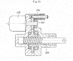
- a shaft 300 serving as a lock member configured to be freely engaged with and disengaged from a gear 400 configured to transmit a driving force from an electric motor 100 to a ball screw 200, and the rotation of the gear 400 is blocked through use of the shaft 300, thereby preventing drive of the ball screw 200.
- Patent Literature 1 JP 5243018 B2
- Patent Literature 1 has the following problem. Specifically, the shaft 300 is arranged at a position far in a radial direction from the ball screw 200 with respect to a rotation center of the gear 400, and hence an axis-to-axis distance between the shaft 300 and the ball screw 200 is thus long. As a result, the size of the electric actuator increases, and a space required for installation increases.
- the present invention has been made in view of the above-mentioned problem, and therefore has an object to provide an electric actuator capable of achieving downsizing.
- an electric actuator comprising: a drive part; a motion conversion mechanism part configured to convert a rotary motion from the drive part into a linear motion in an axial direction in parallel with an output shaft of the drive part; a driving force transmission part comprising a transmission gear mechanism configured to transmit a driving force from the drive part to the motion conversion mechanism part; and a lock mechanism part configured to prevent the drive by the motion conversion mechanism part, wherein the transmission gear mechanism comprises a first gear arranged on the drive part side and a second gear arranged on the motion conversion mechanism part side, and wherein the lock mechanism part is arranged on an opposite side of the drive part with respect to the first gear and on the motion conversion mechanism part side with respect to a rotation center line of the first gear.
- the lock mechanism part can be arranged close to the motion conversion mechanism part without considering interference with the drive part. As a result, the downsizing of the electric actuator can be achieved.
- an electric actuator comprising: a drive part; a motion conversion mechanism part configured to convert a rotary motion from the drive part into a linear motion in an axial direction in parallel with an output shaft of the drive part; a driving force transmission part comprising a transmission gear mechanism configured to transmit a driving force from the drive part to the motion conversion mechanism part; and a lock mechanism part configured to prevent the drive by the motion conversion mechanism part, wherein the transmission gear mechanism comprises a first gear arranged on the drive part side and a second gear arranged on the motion conversion mechanism part side, and wherein the lock mechanism part is configured to restrict a rotation of the first gear so as to prevent the drive by the motion conversion mechanism part through engagement with the first gear on the motion conversion mechanism part side with respect to a rotation center line of the first gear.
- an engagement hole, with which the lock mechanism part is engaged be formed in a side surface of the first gear crossing the axial direction.
- the lock mechanism part is not engaged with teeth of the first gear.
- the lock mechanism part may comprise: a lock member, which is engageable with and disengeable from the engagement hole; and a sliding screw device configured to convert a rotary motion of a rotary motor into a linear motion, to thereby drive the lock member so as to bring the lock member into at least any one of a locking state of engaging the lock member with the engagement hole and an unlocking state of releasing the locking state.
- a sliding screw device configured to convert a rotary motion of a rotary motor into a linear motion, to thereby drive the lock member so as to bring the lock member into at least any one of a locking state of engaging the lock member with the engagement hole and an unlocking state of releasing the locking state.
- the actuator case may comprise a rotation restriction part configured to restrict a rotation of a member of the sliding screw device performing the linear motion. In such a manner, it is not required to independently provide a rotation restriction member, which is advantageous for the downsizing.
- the actuator case can provide the function of the rotation restriction part by fixing one of a sliding screw nut and a sliding screw shaft forming the sliding screw device to the lock member, fixing another one of the sliding screw nut and the sliding screw shaft to an output shaft of the rotary motor, forming a distal end portion side of the lock member into a flat plate shape, and forming, in the actuator case, a through hole having a rectangular cross section into which the distal end portion side of the lock member is inserted.
- the rotation of the lock member is restricted in the through hole through insertion of the distal end portion side of the lock member formed into the flat plate shape into the through hole formed into the rectangular shape in cross section.
- the rotation of the sliding screw nut or the sliding screw shaft fixed to the lock member is restricted, which enables the linear motion.
- the distal end portion side of the lock member be arranged coaxially with the output shaft of the rotary motor.
- a contact portion (rotation restriction portion) between the lock member and the through hole is close to the rotation center line of the rotary motor in the radial direction.
- the lock mechanism part may comprise a spring, which is configured to urge the lock member in a direction that brings the lock member into the locking state, and the rotary motor may be configured to drive the lock member so that the lock member is switched to the unlocking state against an urging force of the spring when the drive part performs driving. In this case, even when power is not supplied to the rotary motor, the locking state can be maintained by the urging force of the spring.
- the rotation of the drive part may be transmitted from the first gear to the second gear while a speed of the rotation is reduced.
- a rotation torque is transmitted from the first gear to the second gear while the rotation torque is increased.
- the electric actuator may further comprise a shaft case, which is configured to accommodate a shaft portion of the motion conversion mechanism part performing the linear motion, and the shaft case may comprise a holder portion, which is configured to hold the lock mechanism part.
- the lock mechanism part is arranged close to the motion conversion mechanism part, and thus downsizing of the shaft case can be achieved.
- the drive part When the lock member is advanced to be engaged with the engagement hole, the drive part may be caused to drive so as to swing the gear in one direction and an opposite direction thereof in the circumferential direction, to thereby match a phase of the engagement hole in the circumferential direction with the lock member.
- the lock member can reliably be inserted into the engagement hole.
- the phase matching can be performed with the small amount of rotation compared with the case in which the gear is rotated in one direction for the phase matching of the engagement hole. Therefore, influence on a stop position of the electric actuator in a linear motion direction is small, and the position can accurately be maintained.
- the electric actuator may further comprise a lock sensor, which is configured to detect advanced and retreated positions of the lock member.
- the lock sensor may be configured to detect the position of the lock member when the lock member is advanced while the gear is being swung, and when insertion of the distal end portion of the lock member into at least the engagement hole is started, and the advance of the lock member may be stopped when a predetermined period has elapsed after the lock sensor detects the position of the lock member.
- the lockmember can reliably be inserted into the engagement hole by detecting the position of the lock member through use of the lock sensor when insertion of the distal end portion of the lock member into at least the engagement hole is started, and by stopping the advance of the lock member when the predetermined period has elapsed after the lock sensor detects the position of the lock member.
- a state of insertion of the lock member into the engagement hole can be managed so as not to be insufficient or excessive by setting the timing of stopping the advance of the lock member to a time point when the predetermined period has elapsed after count is started when insertion of the lock member into at least the engagement hole is started.
- the gear be swung by a width corresponding to an amount of a half pitch of an interval between the engagement holes in each of the one direction and the opposite direction thereof in the circumferential direction.
- the phase of the engagement hole can reliably be matched with the lock member.
- the gear may be swung in the one direction and the opposite direction thereof in the circumferential direction by causing the drive part to drive when the lock member is retreated to be disengaged from the engagement hole.
- an electric actuator suitable for downsizing can be provided.
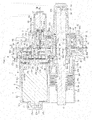
- FIG. 1 is a vertical sectional view for illustrating an assembled state of an electric actuator according to one embodiment of the present invention.
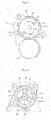
- FIG. 2 is an external perspective view for illustrating the assembled state of the electric actuator.
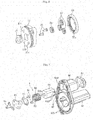
- FIG. 3 is an exploded perspective view of the electric actuator.
- an electric actuator 1 of this embodiment mainly comprises a drive part 2, a motion conversion mechanism part 3, a driving force transmission part 4, a motion-conversion-mechanism support part 5, an operation part 6, and a lock mechanism part 7.
- the drive part 2 is configured to generate a driving force.
- the motion conversion mechanism part 3 is configured to convert a rotary motion from the drive part 2 into a linear motion.
- the driving force transmission part 4 is configured to transmit the driving force from the drive part 2 to the motion conversion mechanism part 3.
- the motion-conversion-mechanism support part 5 is configured to support the motion conversion mechanism part 3.
- the operation part 6 is configured to output the motion of the motion conversion mechanism part 3.
- the lock mechanism part 7 is configured to prevent the motion conversion mechanism part 3 from driving.
- the drive part 2 comprises a motor part 8 and a speed reduction mechanism part 9.
- each of the parts forming the electric actuator 1 has a case. Component parts are accommodated in each of the cases.
- the motor part 8 comprises a motor case 11 configured to accommodate a driving motor 10.
- the speed reduction mechanism part 9 comprises a speed reduction gear case 17 configured to accommodate a speed reduction gear mechanism 16.
- the driving force transmission part 4 comprises a transmission gear case 29 configured to accommodate a transmission gear mechanism 28.
- the motion-conversion-mechanism support part 5 comprises a bearing case 41 configured to accommodate a support bearing 40.
- respective pairs of the motor part 8 and the speed reduction mechanism part 9, the speed reduction mechanism part 9 and the driving force transmission part 4, and the driving force transmission part 4 and the motion-conversion-mechanism support part 5 are configured to be capable of being coupled to and decoupled from one another while the pairs are accommodated in the cases.
- a shaft case 50 is configured to be capable of being coupled to and decoupled from the bearing case 41.
- the motor part 8 mainly comprises the driving motor (DC motor) 10 and the motor case 11.
- the driving motor 10 is configured to drive the motion conversion mechanism part 3.
- the motor case 11 is configured to accommodate the driving motor 10.
- the motor case 11 comprises a case main body 12 and a projecting portion 13.
- the case main body 12 has a bottomed cylindrical shape, and is configured to accommodate the driving motor 10 therein.
- the projecting portion 13 projects from a bottom portion 12a of the case main body 12 to the outside.
- the projecting portion 13 has a hole portion 13a which communicates to an internal space of the case main body 12.
- the hole portion 13a is sealed by a seal member 14 that is made of resin and covers an outer surface of the projecting portion 13.
- an inner peripheral surface of a peripheral wall portion 12b of the case main body 12 is reduced in diameter in a tapered shape from the opening portion 12d side toward the bottom portion 12a side.
- FIG. 4 which is a view of the motor case 11 as seen from the opening portion 12d side, a pair of bus bars 15 configured to connect the driving motor 10 to a power supply is mounted to the case main body 12.
- One end portion 15a of each of the bus bars 15 is connected to a motor terminal 10c through crimping, and another end portion 15b is exposed from the case main body 12 to the outside (see FIG. 2 and FIG. 3 ).
- the end portions 15b of the bus bars 15 exposed to the outside are connected to the power supply.
- the speed reduction mechanism part 9 mainly comprises the speed reduction gear mechanism 16 and the speed reduction gear case 17.
- the speed reduction gear mechanism 16 is configured to reduce the speed of the driving force of the driving motor 10 and output the driving force.
- the speed reduction gear case 17 is configured to accommodate the speed reduction gear mechanism 16.
- the speed reduction gear mechanism 16 is formed of a planetary-gear speed reduction mechanism 18 comprising a plurality of gears and the like. A detailed configuration of the planetary-gear speed reduction mechanism 18 is described later.
- the speed reduction gear case 17 has an accommodating recessed portion 17a configured to accommodate the planetary-gear speed reduction mechanism 18 from an opposite side of the driving motor 10. Moreover, the speed reduction gear case 17 is formed so as to enable a motor adaptor 19 serving as a motor mounting member to be mounted thereto.
- the motor adaptor 19 is a tubular member, and a projection 10d of the driving motor 10 on an output side (right side in FIG. 1 ) is inserted into and fitted to an inner peripheral surface of the motor adaptor 19.
- the speed reduction gear case 17 has a fitting hole 17b to which the motor adaptor 19 is fitted. The motor adaptor 19 is inserted from the driving motor 10 side into the fitting hole 17b and mounted to the fitting hole 17b.
- the speed reduction gear case 17 is configured to be capable of being fitted to the motor case 11 and the transmission gear case 29 described later and arranged on the opposite side of the motor case 11. A portion of the speed reduction gear case 17 arranged on the motor case 11 side is internally fitted to the opening portion 12d side of the motor case 11. A portion of the speed reduction gear case 17 arranged on the transmission gear case 29 side is externally fitted to the transmission gear case 29. Moreover, the speed reduction gear case 17 is fastened to the driving motor 10 through bolts 21 (see FIG. 3 and FIG. 6 ) together with the motor adaptor 19 while being fitted to the motor case 11.
- recessed portions 17c configured to prevent interference with the motor terminals 10c projecting from the driving motor 10 and with the end portions 15a of the bus bars 15 crimped to the motor terminals 10c while the speed reduction gear case 17 and the motor case 11 are fitted to each other.
- a mounting groove 17d configured to mount an O ring 20 is formed in an outer peripheral surface (fitting surface) of the speed reduction gear case 17 to be fitted to an inner peripheral surface of the motor case 11.
- the motion conversion mechanism part 3 is formed of a ball screw 22.
- the ball screw 22 mainly comprises a ball screw nut 23, a ball screw shaft 24, a large number of balls 25, and deflectors 26.
- the ball screw nut 23 serves as a rotary body.
- the ball screw shaft 24 is a shaft portion performing a linear motion.
- the deflectors 26 serve as circulation members. Spiral grooves 23a and 24a are respectively formed in an inner peripheral surface of the ball screw nut 23 and an outer peripheral surface of the ball screw shaft 24.
- the balls 25 are loaded between both of the spiral grooves 23a and 24a, and the deflectors 26 are assembled therebetween. With this configuration, the balls 25 in two rows circulate.
- FIG. 1 is a view for illustrating a state in which the ball screw shaft 24 is arranged at an initial position given when the ball screw shaft 24 retreats most to the right side of FIG. 1 .
- the ball screw shaft 24 is arranged in parallel with the output shaft 10a of the driving motor 10.
- the rotary motion from the driving motor 10 is converted into a linear motion in the axial direction parallel with the output shaft 10a by the ball screw shaft 24.
- a distal end portion (left end portion in FIG. 1 ) of the ball screw shaft 24 in an advancing direction functions as the operation part (actuator head) 6 configured to operate an object device to be operated.
- the driving force transmission part 4 mainly comprises the transmission gear mechanism 28 and the transmission gear case 29.
- the transmission gear mechanism 28 is configured to transmit the driving force from the driving motor 10 of the drive part 2 to the ball screw 22 being the motion conversion mechanism part 3.
- the transmission gear case 29 is configured to accommodate the transmission gear mechanism 28.
- the transmission gear mechanism 28 comprises a drive gear 30 as a first gear on a drive side and a driven gear 31 as a second gear on a driven side meshing with the drive gear 30.
- a gear boss 32 is press-fitted to a rotation center portion of the drive gear 30.
- the drive gear 30 is rotatably supported through intermediation of the gear boss 32 by two rolling bearings 33 and 34 mounted to both the transmission gear case 29 and the bearing case 41 described later.
- the driven gear 31 is press-fitted and fixed to the outer peripheral surface of the ball screw nut 23.
- the transmission gear case 29 comprises an accommodating recessed portion 29a configured to accommodate the drive gear 30 and the driven gear 31 therein. Moreover, the transmission gear case 29 has an insertion hole 29b through which the gear boss 32 is inserted. On an inner peripheral surface of the insertion hole 29b, there is formed a bearing mounting surface 29c to which the one rolling bearing 33 configured to support the gear boss 32 is mounted. Moreover, the transmission gear case 29 comprises an annular projection 29d fitted to an inner peripheral surface of the speed reduction gear case 17. In an outer peripheral surface (fitting surface) of the annular projection 29d, there is formed a mounting groove 29e configured to mount an O ring 35. Moreover, in a surface of the transmission gear case 29 on the bearing case 41 side, there is formed a fitting recessed portion 29f in a groove form fitted to the bearing case 41.
- the transmission gear case 29 comprises a cylindrical portion 29g projecting toward a distal end portion side (left side in FIG. 1 ) of the ball screw shaft 24.
- the cylindrical portion 29g is a portion arranged so as to cover a periphery of the ball screw shaft 24 under a state in which the driven gear 31 is accommodated in the transmission gear case 29, and the ball screw 22 is assembled to the driven gear 31.
- a boot 36 configured to prevent foreign substances from entering the transmission gear case 29 is mounted between the cylindrical portion 29g and the ball screw shaft 24.
- the boot 36 comprises a large-diameter end portion 36a, a small-diameter end portion 36b, and a bellows portion 36c, which connects the large-diameter end portion 36a and the small-diameter end portion 36b to each other, and expands and contracts in the axial direction.
- the large-diameter end portion 36a is fixed to a mounting portion of an outer peripheral surface of the cylindrical portion 29g by tightening a boot band 37.
- the small-diameter end portion 36b is fixed to a mounting portion of the outer peripheral surface of the ball screw shaft 24 by tightening a boot band 38.
- the cylindrical portion 29g has a vent hole 29h which is configured to cause the air to communicate between an inside and an outside of the boot 36 when the boot 36 expands and contracts.
- a boot cover 39 arranged around the boot 36 is provided integrally with the motor case 11.
- the motion-conversion-mechanism support part 5 mainly comprises the support bearing 40 and the bearing case 41.
- the support bearing 40 is configured to support the ball screw 22 being the motion conversion mechanism part 3.
- the bearing case 41 is configured to accommodate the support bearing 40.
- the support bearing 40 is formed of a back-to-back double-row angular contact ball bearing comprising an outer ring 42, an inner ring 43, and balls 44 in a plurality of rows interposed therebetween as main components.
- the support bearing 40 is accommodated in a sleeve 45 formed integrally with the bearing case 41, and is fixed through a snap ring 46 mounted to an inner peripheral surface of the sleeve 45. Moreover, the support bearing 40 is fixed by being press-fitted to an outer peripheral surface of the ball screw nut 23 on a rear end side (right side in FIG. 1 ) of the ball screw shaft 24 with respect to the driven gear 31. A movement in the axial direction of the support bearing 40 and the driven gear 31 fixed to the outer peripheral surface of the ball screw nut 23 is restricted by a restriction projection 23b formed on the ball screw nut 23 on the driven gear 31 side and a restriction member 47 mounted on the support bearing 40 side.
- the restriction member 47 comprises a pair of semicircular members, and is mounted to the outer peripheral surface of the ball screw nut 23 while the semicircular members are combined in an annular form. Further, a pressing collar 48 and a snap ring 49 are mounted to the outer peripheral surface of the ball screw nut 23.
- the pressing collar 48 is configured to hold the restriction member 47.
- the snap ring 49 is configured to prevent the pressing collar 48 from falling off in the axial direction.
- a protruding portion 41a configured to be fitted to the fitting recessed portion 29f of the transmission gear case 29.
- a gear boss accommodating portion 41b configured to accommodate a part of the gear boss 32 projecting from the transmission gear case 29 under a state in which the bearing case 41 is fitted to the transmission gear case 29.
- a bearing mounting surface 41c which is configured to mount the rolling bearing 34 configured to support the gear boss 32.
- the shaft case 50 On an opposite side of the bearing case 41 with respect to the transmission gear case 29 side, the shaft case 50 having a bottomed tubular shape configured to accommodate a rear end portion side (right end portion side in FIG. 1 ) of the ball screw shaft 24 is formed so as to be capable of being fastened through bolts 51 (see FIG. 3 ).
- a mounting groove 50a configured to mount an O ring 52.
- a guide collar 53 is rotatably mounted to each of the both end portions of the pin 27. When the ball screw shaft 24 advances and retreats in the axial direction, the guide collars 53 move along the guide grooves 50b while rotating.
- bolt insertion holes 11a, 17e, 29i, and 41d for inserting bolts 54 configured to assemble and fasten the motor case 11, the speed reduction gear case 17, the transmission gear case 29, and the bearing case 41 are formed in outer peripheries of the respective cases in a radial direction. Further, through holes 29j and 41e configured to mount the assembled electric actuator 1 to an installation location are formed in the outer peripheries in the radial direction of both of the transmission gear case 29 and the bearing case 41.
- FIG. 5 is a transverse sectional view as seen in a direction indicated by the arrows of the line A-A in FIG. 1 .
- FIG. 6 is an exploded perspective view of the planetary-gear speed reduction mechanism 18.
- the planetary-gear speed reduction mechanism 18 comprises a ring gear 55, a sun gear 56, a plurality of planetary gears 57, a planetary gear carrier 58 (see FIG. 1 ), and planetary gear holders 59 (see FIG. 1 ).
- the ring gear 55 comprises a plurality of protrusions 55a projecting in the axial direction. Engagement recessed portions 17f as many as the protrusions 55a are formed in the accommodating recessed portion 17a of the speed reduction gear case 17 (see FIG. 1 ).
- the ring gear 55 is accommodated in the speed reduction gear case 17 while the rotation of the ring gear 55 is stopped.
- the sun gear 56 is arranged at the center of the ring gear 55.
- the output shaft 10a of the driving motor 10 is press-fitted to the sun gear 56.
- the respective planetary gears 57 are arranged between the ring gear 55 and the sun gear 56 so as to mesh with the ring gear 55 and the sun gear 56.
- the respective planetary gears 57 are rotatably supported by the planetary gear carrier 58 and the planetary gear holders 59.
- the planetary gear carrier 58 comprises a cylindrical portion 58a at its center portion.
- the cylindrical portion 58a is press-fitted between an outer peripheral surface of the gear boss 32 and an inner peripheral surface of the rolling bearing 33 (see FIG. 1 ).
- An annular collar 75 is mounted between an inner peripheral surface of the another rolling bearing 34 and the outer peripheral surface of the gear boss 32.
- the sun gear 56 coupled to the output shaft 10a of the driving motor 10 rotates, and, along with this rotation, the respective planetary gears 57 revolve along the ring gear 55 while rotating. Then, the planetary gear carrier 58 is rotated by the revolving motion of the planetary gears 57. With this, the rotation of the driving motor 10 is reduced in speed and transmitted to the drive gear 30, and a rotation torque increases.
- the driving force is transmitted through the planetary-gear speed reduction mechanism 18 in such a manner, a high output of the ball screw shaft 24 can be obtained, and the driving motor 10 can be downsized.
- FIG. 7 is an exploded perspective view of the shaft case 50 and the lock mechanism part 7 mounted thereto.
- FIG. 8 is a transverse sectional view as seen in a direction indicated by the arrows of the line B-B in FIG. 1 .
- the lock mechanism part 7 mainly comprises a lock member 60, a sliding screw nut 61, a sliding screw shaft 62, a lock-member fixation plate 63, a locking motor (DC motor) 64, and a spring 65.
- the lock member 60 is fastened to the sliding screw nut 61 through intermediation of the lock-member fixation plate 63 with bolts 84 (see FIG. 7 ) .
- the locking motor 64 is accommodated in a holder portion 66 formed in the shaft case 50.
- the sliding screw shaft 62 is then mounted to an output shaft 64a of the locking motor 64 projecting from the holder portion 66.
- the spring 65 is arranged on an outer periphery of the sliding screw shaft 62, and the sliding screw nut 61 having the lock member 60 mounted thereto is mounted to the sliding screw shaft 62 through thread engagement. In such a manner, the assembly of the lock mechanism part 7 is completed.
- the holder portion 66 is formed into a bottomed tubular shape, and a cap 67 is mounted on an opposite side of a bottom portion 66a thereof.
- the locking motor 64 is held in abutment against the bottom portion 66a of the holder portion 66 and an inner surface of the cap 67 under a state in which the locking motor 64 is inserted into the holder portion 66 and the cap 67 is mounted. Moreover, under this state, a projection 64b of the locking motor 64 on an output side (left side in FIG. 1 ) is fitted to a fitting hole 66c formed in the bottom portion 66a of the holder portion 66.
- Both of an outer peripheral surface of the main body of the locking motor 64 and an inner peripheral surface of a peripheral wall portion 66b of the holder portion 66 are formed into the same shapes, which are not cylindrical.
- the rotation of the locking motor 64 is restricted through the insertion of the locking motor 64 into the peripheral wall portion 66b of the holder portion 66.
- the cap 67 has a hole portion 67a configured to insert cables 68 connected to motor terminals 64d of the locking motor 64 (see FIG. 8 ).
- Lock-mechanism accommodating recessed portions 66d and 41f are respectively formed in a portion of the shaft case 50 at which the holder portion 66 is formed and a portion of the bearing case 41 opposed thereto.
- a through hole 41g is formed in the lock-mechanism accommodating recessed portion 41f on the bearing case 41 side. As illustrated in FIG.
- the through hole 41g is formed of a hole having a rectangular cross section approximately the same in size and the same in shape as the distal end portion side of the lock member 60 (see FIG. 9 and FIG. 10 ).
- the spring 65 is compressed in the axial direction between the bottom portion 66a of the holder portion 66 and the lock-member fixation plate 63 under the state in which the shaft case 50 is mounted to the bearing case 41.
- the lock member 60 is always urged in an advancing direction (left side in FIG. 1 ) by the compressed spring 65.
- the drive gear 30 is arranged in the advancing direction of the lock member 60.
- the drive gear 30 has engagement holes 30a with which the distal end portion of the lock member 60 can be engaged.
- FIG. 11 which is a transverse sectional view as seen in a direction indicated by the arrows of the line C-C in FIG. 1
- the plurality of engagement holes 30a are formed in a circumferential direction of the drive gear 30.
- the rotation of the drive gear 30 is restricted through the engagement of the lock member 60 with any one of those engagement holes 30a.
- a tilted surface 30b is formed at an entrance portion of each of the engagement holes 30a, and the lock member 60 is thus smoothly inserted into the engagement hole 30a along the tilted surface 30b.
- a lock sensor 69 configured to detect a locking state is mounted to the bearing case 41 (see FIG. 8 ).
- the lock sensor 69 comprises a contact element 69a formed of an elastic member such as a plate spring.
- the lock member 60 advances to be engaged with the engagement hole 30a (brought into a locking state)
- the lock member 60 pushes the contact element 69a so that the lock sensor 69 detects the locking state.
- the lock member 60 When power is not supplied to the locking motor 64, the lock member 60 is held at the advanced position by the spring 65, and is in the locking state in which the distal end portion of the lock member 60 is engaged with the engagement hole 30a of the drive gear 30.
- the power is also supplied to the locking motor 64, and the locking motor 64 drives the lock member 60 in a retreating direction.
- the sliding screw shaft 62 rotates. Meanwhile, the rotation of the sliding screw nut 61 is restricted through the insertion of the flat-plate-shaped distal end portion of the lock member 60 into the through hole 41g having a rectangular cross section.
- the ball screw shaft 24 is held in the state in which the ball screw shaft 24 does not retreat. With this, even when an external force is input from the object device to be operated to the ball screw shaft 24 side, a position of the ball screw shaft 24 can be held at a predetermined position.
- This configuration is particularly preferred for a case in which the electric actuator is applied to an application that requires holding a position of the ball screw shaft 24.
- the lock member 60 is caused to retreat by driving the locking motor 64.
- the locking motor 64 maybe driven to cause the lock member 60 to advance.
- the lock member 60 may be caused to advance and retreat by rotating the locking motor 64 forward and backward.
- a stroke sensor 70 configured to detect a stroke of the ball screw shaft 24 is mounted to the electric actuator 1 of this embodiment (see FIG. 2 and FIG. 3 ).
- the stroke sensor 70 is mounted to a sensor base 71.
- the sensor base 71 is fastened and fixed through bolts 72 to a sensor case 76 formed on an outer peripheral surface between the motor case 11 and the boot cover 39.
- a permanent magnet 73 serving as a sensor target is mounted to an outer peripheral surface of a portion of the ball screw shaft 24 covered with the boot 36 (see FIG. 1 ).
- the permanent magnet 73 is mounted to the ball screw shaft 24 through intermediation of a cylindrical elastic member 74 cut apart at a portion in a circumferential direction.
- a control signal is transmitted from a controller 81 of the control device 80 to the driving motor 10.
- the target value is, for example, a stroke value calculated by an ECU provided at an upper position of a vehicle based on an operation amount when the operation amount is input to the ECU.
- the driving motor 10 When the driving motor 10 receives the control signal, the driving motor 10 starts the rotational drive, and the driving force thereof is transmitted to the ball screw shaft 24 through intermediation of the planetary-gear speed reduction mechanism 18, the drive gear 30, the driven gear 31, and the ball screw nut 23, and the ball screw shaft 24 thus advances. With this, the object device to be operated arranged on the distal end portion side (actuator head side) of the ball screw shaft 24 is operated.
- the stroke value (position in the axial direction) of the ball screw shaft 24 is detected by the stroke sensor 70.
- the detection value detected by the stroke sensor 70 is transmitted to a comparison portion 82 of the control device 80, and a difference between the detection value and the target value is calculated. Then, the driving motor 10 is driven until the detection value matches the target value.
- a shift position can reliably be controlled by feeding back the stroke value detected by the stroke sensor 70 to control the position of the ball screw shaft 24 in such a manner.
- the pressure sensor 83 is provided for the object device to be operated.
- the ECU calculates a required target value (pressure command value) .
- the target value is transmitted to the control device 80, and the control signal is transmitted from the controller 81 to the driving motor 10, the driving motor 10 starts the rotational drive.
- the ball screw shaft 24 advances, and the object device to be operated arranged on the distal end portion side (actuator head side) of the ball screw shaft 24 is operated to pressurize.
- An operation pressure of the ball screw shaft 24 at this time is detected by the pressure sensor 83, and the position of the ball screw shaft 24 is subjected to the feedback control based on the detection value and the target value as in the case of the use of the stroke sensor 70.
- a hydraulic pressure of a brake can reliably be controlled by feeding back the pressure value detected by the pressure sensor 83 to control the position of the ball screw shaft 24 in such a manner.
- the lock mechanism part 7 is arranged on the right side of FIG. 1 with respect to the drive gear 30, in other words, on an opposite side of the drive part 2.
- the lock mechanism part 7 is arranged on the right side of FIG. 1 with respect to the drive gear 30, in other words, on an opposite side of the drive part 2.
- the lock mechanism part 7 When the lock mechanism part 7 is arranged on the same side as the drive part 2, the lock mechanism part 7 needs to be displaced in the axial direction with respect to the drive part 2, or displaced in the radial direction or the circumferential direction orthogonal to the axial direction in order to prevent the interference between the drive part 2 and the lock mechanism part 7, which leads to an increase in size of the electric actuator 1 in the axial direction or the radial direction.
- the lock mechanism part 7 can be arranged directly above the motion conversion mechanism part 3 similarly to the drive part 2 (at a position the same in phase as the drive part 2 in the circumferential direction of the ball screw 22), and an increase in size of the electric actuator 1 can thus be prevented.
- a configuration excellent in weight balance is provided.
- the lock mechanism part 7 is arranged on a bottom side of FIG. 1 with respect to a rotation center line X of the drive gear 30, in other words, on the motion conversion mechanism part 3 side in the radial direction.
- the lock mechanism part 7 can be arranged close to the motion conversion mechanism part 3 in the radial direction (direction orthogonal to the linear motion direction) .
- a portion configured to accommodate the ball screw shaft 24 and the portion (holder portion 66) configured to accommodate the lock mechanism part 7 in the shaft case 50 can be arranged so as to be close to each other.
- the shaft case 50 is downsized, and downsizing of the electric actuator 1 in the vertical direction can be achieved.
- the lock mechanism part 7 is arranged on the motion conversion mechanism part 3 side with respect to the rotation center line X of the drive gear 30" means that more than a half of a vertical dimension (dimension in the up-and-down direction in FIG. 1 ) of the lock mechanism 7 is arranged on the motion conversion mechanism part 3 side with respect to the rotation center line X of the drive gear 30.
- the description may correspond to a case in which the entire lock mechanism part 7 is arranged on the motion conversion mechanism part 3 side with respect to the rotation center line X of the drive gear 30 and to a case in which a part (portion equal to or less than a half of the vertical dimension) of the lock mechanism 7 is arranged on the opposite side of the motion conversion mechanism part 3 with respect to the rotation center line X of the drive gear 30.
- the lock mechanism part 7 is configured to be engaged with the drive gear 30 on the motion conversion mechanism part 3 side with respect to the rotation center line X.
- the arrangement of the lockmechanismpart 7 close to the motion conversion mechanism part 3 is promoted, and the achievement of downsizing of the electric actuator 1 in the vertical direction is thus promoted.
- the engagement holes 30a are formed in a side surface of the drive gear 30 crossing the axial direction, and the lock mechanism part 7 is configured to be engaged with the engagement hole 30a. With this, the lock mechanism part 7 is not engaged with teeth of the drive gear 30. Thus, application of a load on the teeth by the engagement can be prevented, and reliability increases.
- the rotation is transmitted from the drive gear 30 to the driven gear 31 at a constant speed
- the rotation may be transmitted from the drive gear 30 to the driven gear 31 while the speed of the rotation is reduced.
- the drive gear 30 is high in rotation speed and low in rotation torque compared with the driven gear 31.
- the sliding screw device comprising the sliding screw nut 61 and the sliding screw shaft 62 is used as the mechanism configured to convert the rotary motion of the locking motor 64 into the linear motion.
- the linear motion can be achieved through the simple configuration having a small number of parts in the configuration of employing the rotary motor as the driving source.
- further downsizing can be achieved.
- the configuration to restrict the rotation of the member of the sliding screw device performing the linear motion is required.
- the through hole 41g having the rectangular cross section is formed in the baring case 41, and the lock member 60 having the flat plate shape is inserted into the through hole 41g, thereby restricting the rotation of the member (sliding screw nut 61) of the sliding screw device performing the linear motion.
- the bearing case 41 which is a part of the actuator case, has the function as the rotation restriction part. As a result, it is not required to independently provide a member configured to restrict the rotation of the sliding screw nut 61, which is advantageous for the downsizing.
- a projection may be formed on an outer peripheral surface of the sliding screw nut 61, and the rotation of the sliding screw nut 61 may be restricted by bringing the projection into abutment against an inner surface of the bearing case 41.
- the distal end portion side of the lock member 60 is arranged coaxially with the output shaft 64a of the locking motor 64 (see FIG. 1 and FIG. 8 ).
- the rotation can be restricted at the position close to the output shaft 64a in the radial direction, and the resistance against the sliding screw nut 61 can be reduced.
- action performance of the lock member 60 increases, and reliability of the electric actuator increases.
- a portion other than that described below basically has the same configuration as that of the above-mentioned embodiment, and description of the same portion is thus omitted.
- the lock sensor 69 configured to detect the advanced and retreated positions of the lock member 60 in order to recognize whether or not the locking state is brought about is mounted to the bearing case 41 (see FIG. 8 ).
- the lock sensor 69 comprises the contact element 69a formed of an elastic member such as a plate spring. When the lock member 60 advances, the lock member 60 pushes the contact element 69a, and the position of the lock member 60 is thus detected.
- the lock member 60 When power is not supplied to the locking motor 64, the lock member 60 is maintained at the locking position having reached after being advanced by the spring 65, and is in the locking state in which the distal end portion of the lock member 60 is engaged with the engagement hole 30a of the drive gear 30.
- the locking motor 64 rotates backward (rotates in a direction in which the lock member 60 retreats) from this state, the sliding screw shaft 62 rotates along with this backward rotation. At this time, the rotation of the sliding screw nut 61 is restricted through the insertion of the distal end portion in the flat plate shape of the lock member 60 into the through hole 41g having the rectangular cross section.
- the lock member 60 is advanced and retreated through the drive of the locking motor 64.
- the lock member 60 may be advanced only through the urging force of the spring 65.
- the lock member 60 in a case in which the lock member 60 is brought into the locking state, when the phases of the engagement hole 30a and the lock member 60 in the circumferential direction are displaced from each other, the lock member 60 may not be inserted into the engagement hole 30a.
- the phase of the engagement hole 30a in the circumferential direction it is desired that the phase of the engagement hole 30a in the circumferential direction be matched with the position of the lock member 60.
- the inexpensive DC motor brushed motor
- means for detecting a rotation angle of the driving motor 10 is not provided.
- the phase of the engagement hole 30a cannot be matched through use of such rotation angle detection means.
- the electric actuator of this embodiment the following countermeasures are taken.
- the drive gear 30 having the engagement holes 30a is swung, thereby matching the phase of the engagement hole 30a with the lock member 60.
- the driving motor 10 is stopped and then the linear motion of the ball screw 22 is finished, while the lock member 60 is being advanced to be brought into the locking state, the driving motor 10 is caused to rotationally drive alternately in the forward and backward directions, thereby swinging the drive gear 30 in one direction and an opposite direction thereof in the circumferential direction. As illustrated in FIG.
- a swing width W of the drive gear 30 on this occasion is set so that the drive gear 30 is swung by a width corresponding to an amount of a half pitch (1/2P) of an interval between the engagement holes 30a in each of the one direction and the opposite direction thereof in the circumferential direction.
- the swing width W of the drive gear 30 is 30° in total so that the drive gear 30 is swung in each of the one direction and the opposite direction thereof in the circumferential direction by 15° corresponding to the amount of the half pitch (1/2P) of the interval between the engagement holes 30a.
- the lock member 60 advances, and the distal end portion thereof is inserted into the engagement hole 30a. Then, by stopping the advance of the lock member 60, and also stopping the swing of the drive gear 30 under a state in which the distal end portion of the lock member 60 is completely inserted into the engagement hole 30a, the lock member 60 is brought into and maintained in the locking state in which the lock member 30 can be engaged with the engagement hole 30a.
- the drive gear 30 is swung to match the phase of the engagement hole 30a with the lock member 60, thereby being capable of inserting the lock member 60 into the engagement hole 30a.
- the lock member 60 can reliably be inserted into the engagement hole 30a, and the reliability of the device thus increases.
- the rotation amount of rotating the drive gear 30 for the phase matching of the engagement hole 30a can be suppressed to an amount equal to or less than the half pitch of the interval between the engagement holes 30a. Therefore, influence on a stop position in the linear motion direction of the ball screw 22 can be reduced.
- the engagement hole 30a on the left side of FIG. 15 with respect to the lock member 60 needs to be moved toward the right side of FIG. 15 by an amount more than the half pitch.
- the engagement hole 30a on the right side of FIG. 15 with respect to the lock member 60 can be moved toward the left side of FIG. 15 , and hence the phase can be matched by moving the engagement hole 30a on the right side toward the left side of FIG. 15 by an amount less than the half pitch.
- the rotation amount of the drive gear 30 for the phase matching can be reduced.
- the influence on the stop position of the ball screw 22 in the linear motion direction can be reduced, and the stop position in the linear motion direction can accurately be maintained.
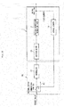
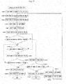
- FIG. 16 is a flowchart for illustrating an example of a control flow when the locking operation is performed.
- the lock sensor 69 detects whether or not the lock member 60 is normally inserted into the engagement hole 30a. Then, when the lock sensor 69 is not turned on (the lock member 60 does not come into contact with the lock sensor 69) even when the lock member 60 is advanced, it is determined that the lock member 60 is not normally inserted into the engagement hole 30a, and a retry operation of once retreating the lock member 60, and again advancing the lock member 60 is carried out.
- a period of the locking operation is counted. Even when the lock sensor 69 is not turned on after a predetermined period, the transition to the retry operation is carried out. Further, the number of times of the retry operation is also counted. Even when the lock sensor 69 is not turned on after the retry operation is carried a predetermined number of times, it is determined that the locking state is not brought about even through further retry operation, and the locking operation is finally finished.
- step 1 When a command of starting the locking operation is issued, first, the count of the number of times of the retry is cleared, thereby resetting the count to an initial state (0 times) (step 1). Further, the locking operation period is cleared, thereby resetting the counted period to an initial state (no counted period) (step 2).
- step 3 the count of the locking operation period is started (step 3), the swing of the drive gear 30 is started (step 4), and the locking motor 64 is rotated forward, thereby starting the advance of the lock member 60 (step 5).
- the lock-sensor-on period is a period set to prevent a false detection due to chattering (swing between on and off) of a switch when the lock sensor 69 is turned on.
- the lock-sensor-on period is set to 0.6 seconds, and the false detection due to the chattering is prevented through waiting for an elapse of 0.6 seconds after the lock sensor 69 is turned on.
- step 7 determination is made on whether or not the locking operation period is more than three seconds (step 7).
- step 8 determination is made on whether or not the lock sensor 69 is turned on (step 8).
- step 10 determination is made on whether or not the lock-sensor-on period is more than 0.6 seconds (step 10).
- the lock sensor 69 has been turned on for more than 0.6 seconds, it is determined that the lock member 60 is inserted into the engagement hole 30a.
- the swing of the drive gear 30 is stopped (step 11), the advance of the lock member 60 is stopped (step 12), and the locking operation is finished.
- step 8 in the determination of whether the lock sensor 69 is turned on or off (step 8), when the locking operation period is more than three seconds while the lock sensor 69 is not turned on ("Yes" in step 7), it is determined that the lock member 60 has not been capable of being inserted into the engagement hole 30a in the predetermined period. Thus, the swing of the drive gear 30 is once stopped (step 13), and the flow proceeds to the retry operation. On this occasion, the maximum number of times of the retry operation is set to three, and hence determination is made on whether or not the current retry operation to be performed is a fourth operation (step 14). When the number of the times of the retry operation is three or less, the retry operation is performed.
- the locking motor 64 is rotated backward, thereby once retreating the lock member 60 (step 15), and the number of times of the retry is counted up (incremented by one) (step 16). Then, the flow proceeds to the operation of clearing the count of the locking operation period (step 2) immediately after the start of the locking operation, and the subsequent operation is performed again.
- step 2 the lock member 60 is inserted into the engagement hole 30a until the locking operation period exceeds three seconds ("Yes" in step 10)
- the swing of the drive gear 30 is stopped as described above (step 11)
- the advance of the lock member 60 is stopped (step 12), and the locking operation is finished.
- step 14 when the lock member 60 is not inserted into the engagement hole 30a after the same retry operation is repeated three times ("Yes" in step 14), it is determined that the lock member 60 cannot be inserted into the engagement hole 30a even through further retry operation. Thus, the advance of the lock member 60 is stopped (step 17), and the operation is finished.
- the drive gear 30 is swung, thereby promoting the engagement of the lock member 60 with the engagement hole 30a during the locking operation. Further, the drive gear 30 may be swung also during the unlocking operation. The reason for this is that when a load is acting from the drive gear 30 to the lock member 60 in the locking state, the lock member 60 may be less likely disengaged from the engagement hole 30a. Therefore, in this embodiment, the lock member 60 is retreated while the drive gear 30 is being swung in one direction and an opposite direction thereof in the circumferential direction during the unlocking operation, thereby being capable of reliably releasing the locking state.
- FIG. 17 is a flowchart for illustrating an example of a control flow when the unlocking operation is performed.
- the lock sensor 69 is configured to detect whether or not the lock member 60 is normally disengaged from the engagement hole 30a. Then, when the lock sensor 69 is not turned off (when the contact of the lock member 60 with the lock sensor 69 is not released) by any chance even when the lock member 60 is retreated, it is determined that the lock member 60 is not normally disengaged from the engagement hole 30a.
- a retry operation of advancing lock member 60 once, and again retreating the lock member 60 is performed. Moreover, in order to measure a timing of transition to the retry operation, a period of the unlocking operation is counted. Even when the lock sensor 69 is not turned off after a predetermined period, the transition to the retry operation is performed. Further, the number of times of the retry operation is also counted, and even when the lock sensor 69 is not turned off after the retry operation is carried a predetermined number of times, it is determined that the unlocking state is not brought about even through further retry operation, and the unlocking operation is finally finished.
- the flow illustrated in FIG. 17 is approximately the same as the flow during the locking operation illustrated in FIG. 16 other than such points that the advance and the retreat of the lock member 60 are reversed, and the ON-state of the lock sensor corresponds to the OFF-state of the lock sensor. Thus, detailed description thereof is omitted.
- FIG. 18 is a flowchart for illustrating another control flow of the locking operation.
- the position of the lock member 60 is detected by the lock sensor 69, and the advance of the lock member 60 is stopped when the predetermined period has elapsed after the timing of the detection.
- the lock member 60 can reliably be inserted into the engagement hole 30a.
- the timing of stopping the advance of the lock member 60 is set to a time point when the predetermined period has elapsed after count is started when insertion of the lock member 60 into at least the engagement hole 30a is started.
- a state of insertion of the lock member 60 into the engagement hole 30a can be managed so as not to be insufficient or excessive.
- the timing of detecting the position of the lock member 60 by the lock sensor 69 may be a timing at which insertion of the distal end portion of the lock member 60 into a portion of the tilted surface 30b is started or a timing at which the distal end portion of the lock member 60 has passed the tilted surface 30b.
- the displacement of the stop position in the linear motion direction (displacement amount X in the linear motion direction of the output shaft of the electric actuator) can be suppressed to the range of from 0.1[mm] to 0.2 [mm] by setting a magnitude of the pitch between the engagement holes 30a so that the rotation amount (rotation angle Y) of the drive gear 30 for the phase matching is 18.75[°] ⁇ Y ⁇ 37.5[°].
- FIG. 20 is a view of the electric actuator 1 according to still another embodiment of the present invention.
- the electric actuator 1 illustrated in FIG. 20 is configured, compared with the electric actuator 1 illustrated in FIG. 1 , by eliminating the speed reduction mechanism part 9, directly coupling the motor part 8 and the driving force transmission part 4 to each other. In this case, the speed reduction mechanism part 9 is not provided.
- the output shaft 10a of the driving motor 10 is press-fitted to the gear boss 32, and the rolling bearing 33 on the transmission gear case 29 side configured to support the gear boss 32 is omitted.
- a member to be fitted to the motor adaptor 19, to which the driving motor 10 is mounted is changed from the speed reduction gear case 17 to the transmission gear case 29, and is thus replaced by one having a different shape conforming to a fitting shape of the member to be fitted to the motor adaptor 19.
- the other configurations are the same as those of the embodiment illustrated in FIG. 1 .
- the electric actuator 1 of the embodiment illustrated in FIG. 20 is controlled to operate basically in the same manner as in the embodiments described above except that the driving force from the driving motor 10 is directly transmitted to the driving force transmission part 4 without intermediation of the speed reduction mechanism part 9. Thus, description of the control and the operation is omitted.
- the lock mechanism part 7 is arranged on the opposite side of the drive part 2 with respect to the drive gear 30, and on the motion conversion mechanism part 3 side with respect to the rotation center line X of the drive gear 30.
- the downsizing of the electric actuator 1 can be achieved.
- the lock mechanism part 7 is configured to be engaged with the drive gear 30 on the motion conversion mechanism part 3 side with respect to the rotation center line X of the drive gear 30, and the downsizing is thus promoted.
- the lock mechanism part 7 can be arranged close to the motion conversion mechanism part 3 without considering the interference with the drive part 2, and hence the downsizing of the electric actuator 1 can be achieved.
- the downsizing of devices and machines on which the electric actuator is mounted can also be achieved.
- the configuration of the electric actuator according to the present invention is also preferred when the electric actuator is produced as series, and is deployed as a plurality of types adapted to applications and usages such as an electric parking brake mechanism for vehicles including two-wheeled vehicles, an electric/hydraulic brake mechanism, an electric shift change mechanism, and an electric power steering as well as a 2WD/4WD electric switching mechanism and an electric shift change mechanism for an outboard engine (for a vessel propulsion engine).
- the lock mechanism part 7 is not limited to one that employs the sliding screw device, but may be one that employs a ball screw device.
- the embodiments employ such a configuration that the sliding screw nut 61 is caused to perform the linear motion by rotating the sliding screw shaft 62.
- the sliding screw shaft 62 may be caused to perform the linear motion by rotating the sliding screw nut 61.
- the sliding screw nut 61 can be rotated by the drive by the locking motor 64, and the sliding screw shaft 62 can be caused to perform a linear motion integrally with the lock member 60.
- the locking motor 64 may be used as the driving source of retreating the lock member 60 release the locking state, the locking motor 64 may be used as a driving source to bring the lock member 60 into the locking state (to advance the lock member 60) or may be used as a driving source to switch the lock member 60 between both of the locking state and the unlocking state (to advance and retreat the lock member 60).
- the support bearing 40 configured to support the motion conversion mechanism part 3 is not limited to the configuration of using the double-row angular contact ball bearing.
- a pair of single-row angular contact ball bearings may be used in combination.
- another double-row bearing using, for example, a deep groove ball bearing may be applied.
- the motion conversion mechanism part 3 may be a sliding screw device.
- the ball screw 22 is more preferred in terms of reducing the rotation torque to downsize the driving motor 10.
- the speed reduction mechanism part 9 may be a speed reduction mechanism other than the planetary-gear speed reduction mechanism 18.
Landscapes
- Engineering & Computer Science (AREA)
- General Engineering & Computer Science (AREA)
- Mechanical Engineering (AREA)
- Power Engineering (AREA)
- Transmission Devices (AREA)
- Connection Of Motors, Electrical Generators, Mechanical Devices, And The Like (AREA)
Abstract
Description
- The present invention relates to an electric actuator.
- In recent years, electrification of automobiles and the like has been promoted for power saving and reduction in fuel consumption. For example, a system for operating an automatic transmission, a brake, a steering wheel, and the like of the automobile with use of power of an electric motor has been developed and brought to the market. As an electric actuator for use in such an application, there has been known an electric linear actuator employing a ball screw mechanism configured to convert a rotary motion of a motor into a motion in a linear direction.
- Incidentally, in the ball screw mechanism, an efficiency of transmission of a driving force to an object device to be operated is very high. However, when an external force is input to the ball screw from a side of the object device to be operated, a ball screw shaft may move in an axial direction. In view of such a problem, hitherto, there has been proposed a ball screw mechanism provided with a lock mechanism configured to prevent the ball screw from being driven by a reverse input from the side of the object device to be operated.
- For example, in
Patent Literature 1, as illustrated inFIG. 21 , there is provided ashaft 300 serving as a lock member configured to be freely engaged with and disengaged from agear 400 configured to transmit a driving force from anelectric motor 100 to aball screw 200, and the rotation of thegear 400 is blocked through use of theshaft 300, thereby preventing drive of theball screw 200. - Patent Literature 1:
JP 5243018 B2 - However, the configuration described in
Patent Literature 1 has the following problem. Specifically, theshaft 300 is arranged at a position far in a radial direction from theball screw 200 with respect to a rotation center of thegear 400, and hence an axis-to-axis distance between theshaft 300 and theball screw 200 is thus long. As a result, the size of the electric actuator increases, and a space required for installation increases. - The present invention has been made in view of the above-mentioned problem, and therefore has an object to provide an electric actuator capable of achieving downsizing.
- According to one embodiment of the present invention, as a technical measure for achieving the above-mentioned object, there is provided an electric actuator, comprising: a drive part; a motion conversion mechanism part configured to convert a rotary motion from the drive part into a linear motion in an axial direction in parallel with an output shaft of the drive part; a driving force transmission part comprising a transmission gear mechanism configured to transmit a driving force from the drive part to the motion conversion mechanism part; and a lock mechanism part configured to prevent the drive by the motion conversion mechanism part, wherein the transmission gear mechanism comprises a first gear arranged on the drive part side and a second gear arranged on the motion conversion mechanism part side, and wherein the lock mechanism part is arranged on an opposite side of the drive part with respect to the first gear and on the motion conversion mechanism part side with respect to a rotation center line of the first gear.
- Through arrangement of the lock mechanism part on the opposite side of the drive part with respect to the first gear and on the motion conversion mechanism part side with respect to the rotation center line of the first gear in such a manner, the lock mechanism part can be arranged close to the motion conversion mechanism part without considering interference with the drive part. As a result, the downsizing of the electric actuator can be achieved.
- According to one embodiment of the present invention, as a technical measure for achieving the above-mentioned object, there is provided an electric actuator, comprising: a drive part; a motion conversion mechanism part configured to convert a rotary motion from the drive part into a linear motion in an axial direction in parallel with an output shaft of the drive part; a driving force transmission part comprising a transmission gear mechanism configured to transmit a driving force from the drive part to the motion conversion mechanism part; and a lock mechanism part configured to prevent the drive by the motion conversion mechanism part, wherein the transmission gear mechanism comprises a first gear arranged on the drive part side and a second gear arranged on the motion conversion mechanism part side, and wherein the lock mechanism part is configured to restrict a rotation of the first gear so as to prevent the drive by the motion conversion mechanism part through engagement with the first gear on the motion conversion mechanism part side with respect to a rotation center line of the first gear.
- With such a configuration that the lock mechanism part is engaged with the first gear on the motion conversion mechanism part side with respect to the rotation center line thereof, the arrangement of the lock mechanism part close to the motion conversion mechanism part is promoted, and the downsizing of the electric actuator is easily achieved.
- For engagement of the lock mechanism part with the first gear, it is preferred that an engagement hole, with which the lock mechanism part is engaged, be formed in a side surface of the first gear crossing the axial direction. In this case, the lock mechanism part is not engaged with teeth of the first gear. Thus, application of a load on the teeth by the engagement can be prevented, and reliability increases.
- The lock mechanism part may comprise: a lock member, which is engageable with and disengeable from the engagement hole; and a sliding screw device configured to convert a rotary motion of a rotary motor into a linear motion, to thereby drive the lock member so as to bring the lock member into at least any one of a locking state of engaging the lock member with the engagement hole and an unlocking state of releasing the locking state. Through use of the sliding screw device in the lock mechanism part, the linear motion can be achieved through the simple configuration comprising a small number of parts, and further downsizing can be achieved.
- Further, the actuator case may comprise a rotation restriction part configured to restrict a rotation of a member of the sliding screw device performing the linear motion. In such a manner, it is not required to independently provide a rotation restriction member, which is advantageous for the downsizing.
- For example, the actuator case can provide the function of the rotation restriction part by fixing one of a sliding screw nut and a sliding screw shaft forming the sliding screw device to the lock member, fixing another one of the sliding screw nut and the sliding screw shaft to an output shaft of the rotary motor, forming a distal end portion side of the lock member into a flat plate shape, and forming, in the actuator case, a through hole having a rectangular cross section into which the distal end portion side of the lock member is inserted. In other words, in this case, the rotation of the lock member is restricted in the through hole through insertion of the distal end portion side of the lock member formed into the flat plate shape into the through hole formed into the rectangular shape in cross section. Thus, the rotation of the sliding screw nut or the sliding screw shaft fixed to the lock member is restricted, which enables the linear motion.
- When the rotation is restricted between the lock member and the through hole as described above, it is preferred that the distal end portion side of the lock member be arranged coaxially with the output shaft of the rotary motor. With this configuration, a contact portion (rotation restriction portion) between the lock member and the through hole is close to the rotation center line of the rotary motor in the radial direction. Thus, a moment received by the rotation restriction portion is reduced, and a resistance against the linear motion of the lock member can be reduced. As a result, action performance of the lock member increases, and reliability of the electric actuator increases.
- The lock mechanism part may comprise a spring, which is configured to urge the lock member in a direction that brings the lock member into the locking state, and the rotary motor may be configured to drive the lock member so that the lock member is switched to the unlocking state against an urging force of the spring when the drive part performs driving. In this case, even when power is not supplied to the rotary motor, the locking state can be maintained by the urging force of the spring.
- The rotation of the drive part may be transmitted from the first gear to the second gear while a speed of the rotation is reduced. In this case, a rotation torque is transmitted from the first gear to the second gear while the rotation torque is increased. Thus, as described above, when the first gear having a lower rotation torque is used as the gear to be engaged with the lock mechanism part, a load applied to the lock mechanism part upon the engagement can be reduced compared with the case of engagement with the second gear having the higher rotation torque. Moreover, in this case, the gear to be engaged with the lock mechanism part is the first gear having a higher rotation speed. Hence, the positioning can finely be carried out compared with the case in which the gear to be engaged with the lock mechanism part is the second gear having a reduced rotation speed, and a position accuracy of stopping the motion conversion mechanism part increases.
- The electric actuator may further comprise a shaft case, which is configured to accommodate a shaft portion of the motion conversion mechanism part performing the linear motion, and the shaft case may comprise a holder portion, which is configured to hold the lock mechanism part. In the electric actuator comprising such a shaft case, as described above, the lock mechanism part is arranged close to the motion conversion mechanism part, and thus downsizing of the shaft case can be achieved.
- When the lock member is advanced to be engaged with the engagement hole, the drive part may be caused to drive so as to swing the gear in one direction and an opposite direction thereof in the circumferential direction, to thereby match a phase of the engagement hole in the circumferential direction with the lock member.
- In such a manner, even when the engagement hole and the lock member are displaced from one another in phase in the circumferential direction, by swinging the gear to match the phase of the engagement hole in the circumferential direction with the lock member, the lock member can reliably be inserted into the engagement hole. Moreover, the phase matching can be performed with the small amount of rotation compared with the case in which the gear is rotated in one direction for the phase matching of the engagement hole. Therefore, influence on a stop position of the electric actuator in a linear motion direction is small, and the position can accurately be maintained.
- The electric actuator may further comprise a lock sensor, which is configured to detect advanced and retreated positions of the lock member. The lock sensor may be configured to detect the position of the lock member when the lock member is advanced while the gear is being swung, and when insertion of the distal end portion of the lock member into at least the engagement hole is started, and the advance of the lock member may be stopped when a predetermined period has elapsed after the lock sensor detects the position of the lock member.
- In such a manner, the lockmember can reliably be inserted into the engagement hole by detecting the position of the lock member through use of the lock sensor when insertion of the distal end portion of the lock member into at least the engagement hole is started, and by stopping the advance of the lock member when the predetermined period has elapsed after the lock sensor detects the position of the lock member. In other words, a state of insertion of the lock member into the engagement hole can be managed so as not to be insufficient or excessive by setting the timing of stopping the advance of the lock member to a time point when the predetermined period has elapsed after count is started when insertion of the lock member into at least the engagement hole is started.
- It is desired that the gear be swung by a width corresponding to an amount of a half pitch of an interval between the engagement holes in each of the one direction and the opposite direction thereof in the circumferential direction.
- Through setting of such a width of the swing of the gear, the phase of the engagement hole can reliably be matched with the lock member.
- The gear may be swung in the one direction and the opposite direction thereof in the circumferential direction by causing the drive part to drive when the lock member is retreated to be disengaged from the engagement hole.
- In such a manner, through swinging of the gear when the lock member is retreated to be disengaged from the engagement hole, the lock member and the gear (an engagement surface of the engagement hole) can be prevented from being stuck, thereby promoting the disengagement of the lock member from the engagement hole. Thus, the locking state can reliably be released.
- According to the present invention, an electric actuator suitable for downsizing can be provided.
-
-
FIG. 1 is a vertical sectional view of an electric actuator according to one embodiment of the present invention. -
FIG. 2 is an external perspective view of the electric actuator. -
FIG. 3 is an exploded perspective view of the electric actuator. -
FIG. 4 is a view of a motor case as seen from an opening portion side. -
FIG. 5 is a transverse sectional view as seen in a direction indicated by the arrows of the line A-A inFIG. 1 . -
FIG. 6 is an exploded perspective view of a speed reduction mechanism part. -
FIG. 7 is an exploded perspective view of a shaft case and a lock mechanism part mounted thereto. -
FIG. 8 is a transverse sectional view as seen in a direction indicated by the arrows of the line B-B inFIG. 1 . -
FIG. 9 is a front view of a bearing case as seen from the left side ofFIG. 1 . -
FIG. 10 is a perspective view for illustrating a state in which a distal end portion of a lock member projects from a through hole. -
FIG. 11 is a transverse sectional view as seen in a direction indicated by the arrows of the line C-C inFIG. 1 . -
FIG. 12 is a control block diagram of the electric actuator. -
FIG. 13 is a control block diagram of the electric actuator. -
FIG. 14 is an explanatory view for illustrating a swing width of a drive gear. -
FIG. 15 is a view for illustrating comparison between a rotation amount in a case in which the drive gear is rotated in one direction for phase matching, and a rotation amount in a case in which the drive gear is swung for the phase matching. -
FIG. 16 is a flowchart for illustrating an example of a control flow when a locking operation is performed. -
FIG. 17 is a flowchart for illustrating an example of a control flow when an unlocking operation is performed. -
FIG. 18 is a flowchart for illustrating another control flow of the locking operation. -
FIG. 19 is an explanatory view for illustrating a timing of detecting a position of the lock member. -
FIG. 20 is a vertical sectional view of the electric actuator according to still another embodiment of the present invention. -
FIG. 21 is a vertical sectional view of a related-art electric linear actuator. - Now, description is made of the present invention with reference to the accompanying drawings. In the respective drawings for illustrating the present invention, components such as members and component parts having the same functions or shapes are denoted by the same reference symbols as long as the components can be distinguished, and description thereof is therefore omitted after the description is made once.
-
FIG. 1 is a vertical sectional view for illustrating an assembled state of an electric actuator according to one embodiment of the present invention.FIG. 2 is an external perspective view for illustrating the assembled state of the electric actuator.FIG. 3 is an exploded perspective view of the electric actuator. - As illustrated in
FIG. 1 , anelectric actuator 1 of this embodiment mainly comprises adrive part 2, a motionconversion mechanism part 3, a drivingforce transmission part 4, a motion-conversion-mechanism support part 5, anoperation part 6, and alock mechanism part 7. Thedrive part 2 is configured to generate a driving force. The motionconversion mechanism part 3 is configured to convert a rotary motion from thedrive part 2 into a linear motion. The drivingforce transmission part 4 is configured to transmit the driving force from thedrive part 2 to the motionconversion mechanism part 3. The motion-conversion-mechanism support part 5 is configured to support the motionconversion mechanism part 3. Theoperation part 6 is configured to output the motion of the motionconversion mechanism part 3. Thelock mechanism part 7 is configured to prevent the motionconversion mechanism part 3 from driving. Moreover, thedrive part 2 comprises amotor part 8 and a speedreduction mechanism part 9. - Each of the parts forming the
electric actuator 1 has a case. Component parts are accommodated in each of the cases. Specifically, themotor part 8 comprises amotor case 11 configured to accommodate a drivingmotor 10. The speedreduction mechanism part 9 comprises a speedreduction gear case 17 configured to accommodate a speedreduction gear mechanism 16. Moreover, the drivingforce transmission part 4 comprises atransmission gear case 29 configured to accommodate atransmission gear mechanism 28. The motion-conversion-mechanism support part 5 comprises a bearingcase 41 configured to accommodate asupport bearing 40. Further, respective pairs of themotor part 8 and the speedreduction mechanism part 9, the speedreduction mechanism part 9 and the drivingforce transmission part 4, and the drivingforce transmission part 4 and the motion-conversion-mechanism support part 5 are configured to be capable of being coupled to and decoupled from one another while the pairs are accommodated in the cases. Further, ashaft case 50 is configured to be capable of being coupled to and decoupled from the bearingcase 41. Now, description is made of detailed configurations of the respective parts forming theelectric actuator 1. - The
motor part 8 mainly comprises the driving motor (DC motor) 10 and themotor case 11. The drivingmotor 10 is configured to drive the motionconversion mechanism part 3. Themotor case 11 is configured to accommodate the drivingmotor 10. Themotor case 11 comprises a casemain body 12 and a projectingportion 13. The casemain body 12 has a bottomed cylindrical shape, and is configured to accommodate the drivingmotor 10 therein. The projectingportion 13 projects from abottom portion 12a of the casemain body 12 to the outside. The projectingportion 13 has ahole portion 13a which communicates to an internal space of the casemain body 12. Thehole portion 13a is sealed by aseal member 14 that is made of resin and covers an outer surface of the projectingportion 13. - Under a state in which the driving
motor 10 is inserted from anopening portion 12d of the casemain body 12 into an inside of the casemain body 12, an end surface of the drivingmotor 10 on an inner side in an insertion direction is held in abutment against thebottom portion 12a of the casemain body 12. Moreover, afitting hole 12c is formed in a center portion of thebottom portion 12a. Aprojection 10b of the drivingmotor 10 in the inner side in the insertion direction is fitted to thefitting hole 12c, thereby preventing interference of a rear end (left end portion inFIG. 1 ) of anoutput shaft 10a projecting from theprojection 10b with thebottom portion 12a of themotor case 11. Further, an inner peripheral surface of aperipheral wall portion 12b of the casemain body 12 is reduced in diameter in a tapered shape from theopening portion 12d side toward thebottom portion 12a side. When the drivingmotor 10 is inserted into the casemain body 12, an outer peripheral surface of the drivingmotor 10 on the inner side in the insertion direction comes into contact with the inner peripheral surface of theperipheral wall portion 12b. With this configuration, the drivingmotor 10 is supported through the contact with the inner peripheral surface of the casemain body 12 and the fitting to thefitting hole 12c under the state in which the drivingmotor 10 is inserted into the casemain body 12. - Moreover, as illustrated in
FIG. 4 , which is a view of themotor case 11 as seen from theopening portion 12d side, a pair ofbus bars 15 configured to connect the drivingmotor 10 to a power supply is mounted to the casemain body 12. Oneend portion 15a of each of the bus bars 15 is connected to amotor terminal 10c through crimping, and anotherend portion 15b is exposed from the casemain body 12 to the outside (seeFIG. 2 andFIG. 3 ). Theend portions 15b of the bus bars 15 exposed to the outside are connected to the power supply. - Next, description is made of the speed
reduction mechanism part 9. - As illustrated in
FIG. 1 , the speedreduction mechanism part 9 mainly comprises the speedreduction gear mechanism 16 and the speedreduction gear case 17. The speedreduction gear mechanism 16 is configured to reduce the speed of the driving force of the drivingmotor 10 and output the driving force. The speedreduction gear case 17 is configured to accommodate the speedreduction gear mechanism 16. The speedreduction gear mechanism 16 is formed of a planetary-gearspeed reduction mechanism 18 comprising a plurality of gears and the like. A detailed configuration of the planetary-gearspeed reduction mechanism 18 is described later. - The speed
reduction gear case 17 has an accommodating recessedportion 17a configured to accommodate the planetary-gearspeed reduction mechanism 18 from an opposite side of the drivingmotor 10. Moreover, the speedreduction gear case 17 is formed so as to enable amotor adaptor 19 serving as a motor mounting member to be mounted thereto. Themotor adaptor 19 is a tubular member, and aprojection 10d of the drivingmotor 10 on an output side (right side inFIG. 1 ) is inserted into and fitted to an inner peripheral surface of themotor adaptor 19. The speedreduction gear case 17 has afitting hole 17b to which themotor adaptor 19 is fitted. Themotor adaptor 19 is inserted from the drivingmotor 10 side into thefitting hole 17b and mounted to thefitting hole 17b. - The speed
reduction gear case 17 is configured to be capable of being fitted to themotor case 11 and thetransmission gear case 29 described later and arranged on the opposite side of themotor case 11. A portion of the speedreduction gear case 17 arranged on themotor case 11 side is internally fitted to theopening portion 12d side of themotor case 11. A portion of the speedreduction gear case 17 arranged on thetransmission gear case 29 side is externally fitted to thetransmission gear case 29. Moreover, the speedreduction gear case 17 is fastened to the drivingmotor 10 through bolts 21 (seeFIG. 3 andFIG. 6 ) together with themotor adaptor 19 while being fitted to themotor case 11. On the drivingmotor 10 side of the speedreduction gear case 17, there are formed recessedportions 17c configured to prevent interference with themotor terminals 10c projecting from the drivingmotor 10 and with theend portions 15a of the bus bars 15 crimped to themotor terminals 10c while the speedreduction gear case 17 and themotor case 11 are fitted to each other. Moreover, a mountinggroove 17d configured to mount anO ring 20 is formed in an outer peripheral surface (fitting surface) of the speedreduction gear case 17 to be fitted to an inner peripheral surface of themotor case 11. - Next, description is made of the motion
conversion mechanism part 3. - The motion
conversion mechanism part 3 is formed of aball screw 22. The ball screw 22 mainly comprises aball screw nut 23, aball screw shaft 24, a large number ofballs 25, anddeflectors 26. The ball screwnut 23 serves as a rotary body. The ball screwshaft 24 is a shaft portion performing a linear motion. Thedeflectors 26 serve as circulation members.Spiral grooves ball screw nut 23 and an outer peripheral surface of theball screw shaft 24. Theballs 25 are loaded between both of thespiral grooves deflectors 26 are assembled therebetween. With this configuration, theballs 25 in two rows circulate. - The ball screw
nut 23 receives the driving force from the drivingmotor 10, to thereby rotate in a forward direction or a backward direction. Meanwhile, the rotation of theball screw shaft 24 is restricted by apin 27 that is provided on a rear end portion (right end portion inFIG. 1 ) thereof and serves as a rotation restriction member. Therefore, when theball screw nut 23 rotates, theballs 25 circulate along both thespiral grooves deflectors 26, and theball screw shaft 24 advances and retreats in the axial direction.FIG. 1 is a view for illustrating a state in which theball screw shaft 24 is arranged at an initial position given when theball screw shaft 24 retreats most to the right side ofFIG. 1 . Moreover, theball screw shaft 24 is arranged in parallel with theoutput shaft 10a of the drivingmotor 10. The rotary motion from the drivingmotor 10 is converted into a linear motion in the axial direction parallel with theoutput shaft 10a by theball screw shaft 24. A distal end portion (left end portion inFIG. 1 ) of theball screw shaft 24 in an advancing direction functions as the operation part (actuator head) 6 configured to operate an object device to be operated. - Next, description is made of the driving
force transmission part 4. - The driving
force transmission part 4 mainly comprises thetransmission gear mechanism 28 and thetransmission gear case 29. Thetransmission gear mechanism 28 is configured to transmit the driving force from the drivingmotor 10 of thedrive part 2 to theball screw 22 being the motionconversion mechanism part 3. Thetransmission gear case 29 is configured to accommodate thetransmission gear mechanism 28. Thetransmission gear mechanism 28 comprises adrive gear 30 as a first gear on a drive side and a drivengear 31 as a second gear on a driven side meshing with thedrive gear 30. - A
gear boss 32 is press-fitted to a rotation center portion of thedrive gear 30. Thedrive gear 30 is rotatably supported through intermediation of thegear boss 32 by two rollingbearings transmission gear case 29 and the bearingcase 41 described later. Meanwhile, the drivengear 31 is press-fitted and fixed to the outer peripheral surface of theball screw nut 23. When the driving force from the drivingmotor 10 is transmitted to thedrive gear 30 through intermediation of the planetary-gearspeed reduction mechanism 18, the drivengear 31 and theball screw nut 23 integrally rotate, and theball screw shaft 24 advances and retreats. - The
transmission gear case 29 comprises an accommodating recessedportion 29a configured to accommodate thedrive gear 30 and the drivengear 31 therein. Moreover, thetransmission gear case 29 has aninsertion hole 29b through which thegear boss 32 is inserted. On an inner peripheral surface of theinsertion hole 29b, there is formed abearing mounting surface 29c to which the one rollingbearing 33 configured to support thegear boss 32 is mounted. Moreover, thetransmission gear case 29 comprises anannular projection 29d fitted to an inner peripheral surface of the speedreduction gear case 17. In an outer peripheral surface (fitting surface) of theannular projection 29d, there is formed a mountinggroove 29e configured to mount anO ring 35. Moreover, in a surface of thetransmission gear case 29 on the bearingcase 41 side, there is formed a fitting recessedportion 29f in a groove form fitted to the bearingcase 41. - Moreover, the
transmission gear case 29 comprises a cylindrical portion 29g projecting toward a distal end portion side (left side inFIG. 1 ) of theball screw shaft 24. The cylindrical portion 29g is a portion arranged so as to cover a periphery of theball screw shaft 24 under a state in which the drivengear 31 is accommodated in thetransmission gear case 29, and theball screw 22 is assembled to the drivengear 31. Aboot 36 configured to prevent foreign substances from entering thetransmission gear case 29 is mounted between the cylindrical portion 29g and theball screw shaft 24. Theboot 36 comprises a large-diameter end portion 36a, a small-diameter end portion 36b, and abellows portion 36c, which connects the large-diameter end portion 36a and the small-diameter end portion 36b to each other, and expands and contracts in the axial direction. The large-diameter end portion 36a is fixed to a mounting portion of an outer peripheral surface of the cylindrical portion 29g by tightening aboot band 37. The small-diameter end portion 36b is fixed to a mounting portion of the outer peripheral surface of theball screw shaft 24 by tightening aboot band 38. Moreover, the cylindrical portion 29g has avent hole 29h which is configured to cause the air to communicate between an inside and an outside of theboot 36 when theboot 36 expands and contracts. Moreover, aboot cover 39 arranged around theboot 36 is provided integrally with themotor case 11. - Next, description is made of the motion-conversion-
mechanism support part 5. - The motion-conversion-
mechanism support part 5 mainly comprises the support bearing 40 and the bearingcase 41. Thesupport bearing 40 is configured to support theball screw 22 being the motionconversion mechanism part 3. The bearingcase 41 is configured to accommodate thesupport bearing 40. Thesupport bearing 40 is formed of a back-to-back double-row angular contact ball bearing comprising anouter ring 42, aninner ring 43, andballs 44 in a plurality of rows interposed therebetween as main components. - The
support bearing 40 is accommodated in asleeve 45 formed integrally with the bearingcase 41, and is fixed through asnap ring 46 mounted to an inner peripheral surface of thesleeve 45. Moreover, the support bearing 40 is fixed by being press-fitted to an outer peripheral surface of theball screw nut 23 on a rear end side (right side inFIG. 1 ) of theball screw shaft 24 with respect to the drivengear 31. A movement in the axial direction of the support bearing 40 and the drivengear 31 fixed to the outer peripheral surface of theball screw nut 23 is restricted by arestriction projection 23b formed on theball screw nut 23 on the drivengear 31 side and arestriction member 47 mounted on the support bearing 40 side. Therestriction member 47 comprises a pair of semicircular members, and is mounted to the outer peripheral surface of theball screw nut 23 while the semicircular members are combined in an annular form. Further, apressing collar 48 and asnap ring 49 are mounted to the outer peripheral surface of theball screw nut 23. Thepressing collar 48 is configured to hold therestriction member 47. Thesnap ring 49 is configured to prevent thepressing collar 48 from falling off in the axial direction. - On the
transmission gear case 29 side of the bearingcase 41, there is formed a protrudingportion 41a configured to be fitted to the fitting recessedportion 29f of thetransmission gear case 29. Moreover, on thetransmission gear case 29 side of the bearingcase 41, there is formed a gearboss accommodating portion 41b configured to accommodate a part of thegear boss 32 projecting from thetransmission gear case 29 under a state in which thebearing case 41 is fitted to thetransmission gear case 29. On an inner peripheral surface of the gearboss accommodating portion 41b, there is formed abearing mounting surface 41c which is configured to mount the rollingbearing 34 configured to support thegear boss 32. - On an opposite side of the bearing
case 41 with respect to thetransmission gear case 29 side, theshaft case 50 having a bottomed tubular shape configured to accommodate a rear end portion side (right end portion side inFIG. 1 ) of theball screw shaft 24 is formed so as to be capable of being fastened through bolts 51 (seeFIG. 3 ). In an abutment surface of theshaft case 50 against the bearingcase 41, there is formed a mountinggroove 50a configured to mount anO ring 52. Moreover, in an inner peripheral surface of theshaft case 50, guidegrooves 50b into which both end portions of thepin 27 provided on theball screw shaft 24 are formed so as to extend in the axial direction. Aguide collar 53 is rotatably mounted to each of the both end portions of thepin 27. When theball screw shaft 24 advances and retreats in the axial direction, theguide collars 53 move along theguide grooves 50b while rotating. - As illustrated in
FIG. 3 ,bolt insertion holes bolts 54 configured to assemble and fasten themotor case 11, the speedreduction gear case 17, thetransmission gear case 29, and the bearingcase 41 are formed in outer peripheries of the respective cases in a radial direction. Further, throughholes electric actuator 1 to an installation location are formed in the outer peripheries in the radial direction of both of thetransmission gear case 29 and the bearingcase 41. - Now, description is made of the planetary-gear
speed reduction mechanism 18 with reference toFIG. 1 ,FIG. 5 , andFIG. 6 . -
FIG. 5 is a transverse sectional view as seen in a direction indicated by the arrows of the line A-A inFIG. 1 .FIG. 6 is an exploded perspective view of the planetary-gearspeed reduction mechanism 18. - The planetary-gear
speed reduction mechanism 18 comprises aring gear 55, asun gear 56, a plurality ofplanetary gears 57, a planetary gear carrier 58 (seeFIG. 1 ), and planetary gear holders 59 (seeFIG. 1 ). Thering gear 55 comprises a plurality ofprotrusions 55a projecting in the axial direction. Engagement recessedportions 17f as many as theprotrusions 55a are formed in the accommodating recessedportion 17a of the speed reduction gear case 17 (seeFIG. 1 ). Through assembly of theprotrusions 55a of thering gear 55 to the engagement recessedportions 17f of the speedreduction gear case 17 while theprotrusions 55a and the engagement recessedportions 17f are in phase, thering gear 55 is accommodated in the speedreduction gear case 17 while the rotation of thering gear 55 is stopped. - The
sun gear 56 is arranged at the center of thering gear 55. Theoutput shaft 10a of the drivingmotor 10 is press-fitted to thesun gear 56. Moreover, the respectiveplanetary gears 57 are arranged between thering gear 55 and thesun gear 56 so as to mesh with thering gear 55 and thesun gear 56. The respectiveplanetary gears 57 are rotatably supported by theplanetary gear carrier 58 and theplanetary gear holders 59. Theplanetary gear carrier 58 comprises a cylindrical portion 58a at its center portion. The cylindrical portion 58a is press-fitted between an outer peripheral surface of thegear boss 32 and an inner peripheral surface of the rolling bearing 33 (seeFIG. 1 ). Anannular collar 75 is mounted between an inner peripheral surface of the another rollingbearing 34 and the outer peripheral surface of thegear boss 32. - In the planetary-gear
speed reduction mechanism 18 having the configuration described above, when the drivingmotor 10 performs the rotational drive, thesun gear 56 coupled to theoutput shaft 10a of the drivingmotor 10 rotates, and, along with this rotation, the respectiveplanetary gears 57 revolve along thering gear 55 while rotating. Then, theplanetary gear carrier 58 is rotated by the revolving motion of the planetary gears 57. With this, the rotation of the drivingmotor 10 is reduced in speed and transmitted to thedrive gear 30, and a rotation torque increases. When the driving force is transmitted through the planetary-gearspeed reduction mechanism 18 in such a manner, a high output of theball screw shaft 24 can be obtained, and the drivingmotor 10 can be downsized. - Next, description is made of the
lock mechanism part 7 with reference toFIG. 1 ,FIG. 7 , andFIG. 8 .FIG. 7 is an exploded perspective view of theshaft case 50 and thelock mechanism part 7 mounted thereto.FIG. 8 is a transverse sectional view as seen in a direction indicated by the arrows of the line B-B inFIG. 1 . - The
lock mechanism part 7 mainly comprises alock member 60, a slidingscrew nut 61, a slidingscrew shaft 62, a lock-member fixation plate 63, a locking motor (DC motor) 64, and aspring 65. When thelock mechanism part 7 is to be assembled, first, thelock member 60 is fastened to the slidingscrew nut 61 through intermediation of the lock-member fixation plate 63 with bolts 84 (seeFIG. 7 ) . Next, the lockingmotor 64 is accommodated in aholder portion 66 formed in theshaft case 50. The slidingscrew shaft 62 is then mounted to anoutput shaft 64a of the lockingmotor 64 projecting from theholder portion 66. Then, thespring 65 is arranged on an outer periphery of the slidingscrew shaft 62, and the slidingscrew nut 61 having thelock member 60 mounted thereto is mounted to the slidingscrew shaft 62 through thread engagement. In such a manner, the assembly of thelock mechanism part 7 is completed. - The
holder portion 66 is formed into a bottomed tubular shape, and acap 67 is mounted on an opposite side of abottom portion 66a thereof. The lockingmotor 64 is held in abutment against thebottom portion 66a of theholder portion 66 and an inner surface of thecap 67 under a state in which the lockingmotor 64 is inserted into theholder portion 66 and thecap 67 is mounted. Moreover, under this state, aprojection 64b of the lockingmotor 64 on an output side (left side inFIG. 1 ) is fitted to afitting hole 66c formed in thebottom portion 66a of theholder portion 66. Both of an outer peripheral surface of the main body of the lockingmotor 64 and an inner peripheral surface of aperipheral wall portion 66b of theholder portion 66 are formed into the same shapes, which are not cylindrical. Thus, the rotation of the lockingmotor 64 is restricted through the insertion of the lockingmotor 64 into theperipheral wall portion 66b of theholder portion 66. Through accommodation of the lockingmotor 64 in theholder portion 66 in such a manner, the lockingmotor 64 is held by theholder portion 66, and the entirelock mechanism part 7 is held. Moreover, thecap 67 has ahole portion 67a configured to insertcables 68 connected tomotor terminals 64d of the locking motor 64 (seeFIG. 8 ). - Lock-mechanism accommodating recessed
portions shaft case 50 at which theholder portion 66 is formed and a portion of the bearingcase 41 opposed thereto. A throughhole 41g is formed in the lock-mechanism accommodating recessedportion 41f on the bearingcase 41 side. As illustrated inFIG. 1 , a part of theoutput shaft 64a of the lockingmotor 64, the slidingscrew shaft 62, the slidingscrew nut 61, the lock-member fixation plate 63, thespring 65, and thelock member 60, which project from theholder portion 66, are accommodated in the lock-mechanism accommodating recessedportions lock member 60 having a flat plate shape is inserted into the throughhole 41g under a state in which theshaft case 50 is mounted to the bearingcase 41. The throughhole 41g is formed of a hole having a rectangular cross section approximately the same in size and the same in shape as the distal end portion side of the lock member 60 (seeFIG. 9 andFIG. 10 ). Moreover, thespring 65 is compressed in the axial direction between thebottom portion 66a of theholder portion 66 and the lock-member fixation plate 63 under the state in which theshaft case 50 is mounted to the bearingcase 41. Thelock member 60 is always urged in an advancing direction (left side inFIG. 1 ) by thecompressed spring 65. - The
drive gear 30 is arranged in the advancing direction of thelock member 60. Thedrive gear 30 hasengagement holes 30a with which the distal end portion of thelock member 60 can be engaged. As illustrated inFIG. 11 , which is a transverse sectional view as seen in a direction indicated by the arrows of the line C-C inFIG. 1 , the plurality ofengagement holes 30a are formed in a circumferential direction of thedrive gear 30. The rotation of thedrive gear 30 is restricted through the engagement of thelock member 60 with any one of thoseengagement holes 30a. Moreover, a tiltedsurface 30b is formed at an entrance portion of each of theengagement holes 30a, and thelock member 60 is thus smoothly inserted into theengagement hole 30a along the tiltedsurface 30b. - A
lock sensor 69 configured to detect a locking state is mounted to the bearing case 41 (seeFIG. 8 ). Thelock sensor 69 comprises acontact element 69a formed of an elastic member such as a plate spring. When thelock member 60 advances to be engaged with theengagement hole 30a (brought into a locking state), thelock member 60 pushes thecontact element 69a so that thelock sensor 69 detects the locking state. - Now, description is made of an operation of the
lock mechanism part 7. - When power is not supplied to the locking
motor 64, thelock member 60 is held at the advanced position by thespring 65, and is in the locking state in which the distal end portion of thelock member 60 is engaged with theengagement hole 30a of thedrive gear 30. When the power is supplied to the drivingmotor 10 in order to start the driving of theball screw shaft 24 in this state, the power is also supplied to the lockingmotor 64, and the lockingmotor 64 drives thelock member 60 in a retreating direction. With this, the slidingscrew shaft 62 rotates. Meanwhile, the rotation of the slidingscrew nut 61 is restricted through the insertion of the flat-plate-shaped distal end portion of thelock member 60 into the throughhole 41g having a rectangular cross section. Thus, when the slidingscrew shaft 62 rotates, the slidingscrew nut 61 retreats against the urging force of thespring 65, and thelock member 60 retreats integrally with the slidingscrew nut 61. With this, the distal end portion of thelock member 60 is disengaged from theengagement hole 30a of thedrive gear 30, and the locking state is thus released. In this way, while theball screw shaft 24 is being driven, thelock member 60 is held at the retreated position, and thedrive gear 30 is thus held in the unlocked state (unlocking state). - After that, when the supply of power to the driving
motor 10 is shut off and the drive of theball screw shaft 24 is thus stopped, the supply of power to the lockingmotor 64 is also shut off. With this, the driving force for causing thelock member 60 to retreat is no longer generated, and thelock member 60 is thus pushed to move in the advancing direction by thespring 65. Then, the locking state is brought about through the engagement of the distal end portion of thelock member 60 with theengagement hole 30a of thedrive gear 30, thereby restricting the rotation of thedrive gear 30. - Through restriction of the rotation of the
drive gear 30 by thelock member 60 in such a manner, theball screw shaft 24 is held in the state in which theball screw shaft 24 does not retreat. With this, even when an external force is input from the object device to be operated to theball screw shaft 24 side, a position of theball screw shaft 24 can be held at a predetermined position. This configuration is particularly preferred for a case in which the electric actuator is applied to an application that requires holding a position of theball screw shaft 24. - In this embodiment, the
lock member 60 is caused to retreat by driving the lockingmotor 64. Conversely, the lockingmotor 64 maybe driven to cause thelock member 60 to advance. Moreover, thelock member 60 may be caused to advance and retreat by rotating the lockingmotor 64 forward and backward. - A
stroke sensor 70 configured to detect a stroke of theball screw shaft 24 is mounted to theelectric actuator 1 of this embodiment (seeFIG. 2 andFIG. 3 ). Thestroke sensor 70 is mounted to asensor base 71. Thesensor base 71 is fastened and fixed throughbolts 72 to asensor case 76 formed on an outer peripheral surface between themotor case 11 and theboot cover 39. Meanwhile, apermanent magnet 73 serving as a sensor target is mounted to an outer peripheral surface of a portion of theball screw shaft 24 covered with the boot 36 (seeFIG. 1 ). In this embodiment, thepermanent magnet 73 is mounted to theball screw shaft 24 through intermediation of a cylindricalelastic member 74 cut apart at a portion in a circumferential direction. When theball screw shaft 24 advances and retreats, a position of themagnet 73 with respect to thestroke sensor 70 changes, and the position of theball screw shaft 24 in the axial direction can be recognized through thestroke sensor 70 detecting a change in direction of line of magnetic force that changes along with the change in position of themagnet 73. - Next, with reference to
FIG. 12 , description is made of feedback control using thestroke sensor 70. - As illustrated in
FIG. 12 , when a target value is transmitted to acontrol device 80, a control signal is transmitted from acontroller 81 of thecontrol device 80 to the drivingmotor 10. The target value is, for example, a stroke value calculated by an ECU provided at an upper position of a vehicle based on an operation amount when the operation amount is input to the ECU. - When the driving
motor 10 receives the control signal, the drivingmotor 10 starts the rotational drive, and the driving force thereof is transmitted to theball screw shaft 24 through intermediation of the planetary-gearspeed reduction mechanism 18, thedrive gear 30, the drivengear 31, and theball screw nut 23, and theball screw shaft 24 thus advances. With this, the object device to be operated arranged on the distal end portion side (actuator head side) of theball screw shaft 24 is operated. - At this time, the stroke value (position in the axial direction) of the
ball screw shaft 24 is detected by thestroke sensor 70. The detection value detected by thestroke sensor 70 is transmitted to acomparison portion 82 of thecontrol device 80, and a difference between the detection value and the target value is calculated. Then, the drivingmotor 10 is driven until the detection value matches the target value. When theelectric actuator 1 of this embodiment is applied to, for example, a shift-by-wire system, a shift position can reliably be controlled by feeding back the stroke value detected by thestroke sensor 70 to control the position of theball screw shaft 24 in such a manner. - Next, with reference to
FIG. 13 , description is made of feedback control in a case in which apressure sensor 83 is used in place of thestroke sensor 70. - As illustrated in
FIG. 13 , in this case, thepressure sensor 83 is provided for the object device to be operated. When the operation amount is input to the ECU provided at the upper position of the vehicle, the ECU calculates a required target value (pressure command value) . When the target value is transmitted to thecontrol device 80, and the control signal is transmitted from thecontroller 81 to the drivingmotor 10, the drivingmotor 10 starts the rotational drive. With this, theball screw shaft 24 advances, and the object device to be operated arranged on the distal end portion side (actuator head side) of theball screw shaft 24 is operated to pressurize. - An operation pressure of the
ball screw shaft 24 at this time is detected by thepressure sensor 83, and the position of theball screw shaft 24 is subjected to the feedback control based on the detection value and the target value as in the case of the use of thestroke sensor 70. When theelectric actuator 1 of this embodiment is applied to, for example, a brake-by-wire system, a hydraulic pressure of a brake can reliably be controlled by feeding back the pressure value detected by thepressure sensor 83 to control the position of theball screw shaft 24 in such a manner. - The configuration and the operation of the
electric actuator 1 of this embodiment are as described above. Now, description is made of components suitable for downsizing relating to theelectric actuator 1 of this embodiment. - As illustrated in
FIG. 1 , in this embodiment, thelock mechanism part 7 is arranged on the right side ofFIG. 1 with respect to thedrive gear 30, in other words, on an opposite side of thedrive part 2. Thus, through the arrangement of thelock mechanism part 7 on the opposite side of thedrive part 2, interference with thedrive part 2 does not need to be considered on the side on which thelock mechanism part 7 is arranged. When thelock mechanism part 7 is arranged on the same side as thedrive part 2, thelock mechanism part 7 needs to be displaced in the axial direction with respect to thedrive part 2, or displaced in the radial direction or the circumferential direction orthogonal to the axial direction in order to prevent the interference between thedrive part 2 and thelock mechanism part 7, which leads to an increase in size of theelectric actuator 1 in the axial direction or the radial direction. In contrast, in this embodiment, as illustrated inFIG. 1 , thelock mechanism part 7 can be arranged directly above the motionconversion mechanism part 3 similarly to the drive part 2 (at a position the same in phase as thedrive part 2 in the circumferential direction of the ball screw 22), and an increase in size of theelectric actuator 1 can thus be prevented. Moreover, a configuration excellent in weight balance is provided. - Further, in this embodiment, the
lock mechanism part 7 is arranged on a bottom side ofFIG. 1 with respect to a rotation center line X of thedrive gear 30, in other words, on the motionconversion mechanism part 3 side in the radial direction. Thus, through the arrangement of thelock mechanism part 7 on the motionconversion mechanism part 3 side with respect to the rotation center line X of thedrive gear 30, thelock mechanism part 7 can be arranged close to the motionconversion mechanism part 3 in the radial direction (direction orthogonal to the linear motion direction) . Similarly, a portion configured to accommodate theball screw shaft 24 and the portion (holder portion 66) configured to accommodate thelock mechanism part 7 in theshaft case 50 can be arranged so as to be close to each other. As a result, theshaft case 50 is downsized, and downsizing of theelectric actuator 1 in the vertical direction can be achieved. - The above description "the
lock mechanism part 7 is arranged on the motionconversion mechanism part 3 side with respect to the rotation center line X of thedrive gear 30" means that more than a half of a vertical dimension (dimension in the up-and-down direction inFIG. 1 ) of thelock mechanism 7 is arranged on the motionconversion mechanism part 3 side with respect to the rotation center line X of thedrive gear 30. In other words, the description may correspond to a case in which the entirelock mechanism part 7 is arranged on the motionconversion mechanism part 3 side with respect to the rotation center line X of thedrive gear 30 and to a case in which a part (portion equal to or less than a half of the vertical dimension) of thelock mechanism 7 is arranged on the opposite side of the motionconversion mechanism part 3 with respect to the rotation center line X of thedrive gear 30. - Moreover, as illustrated in
FIG. 1 , in this embodiment, thelock mechanism part 7 is configured to be engaged with thedrive gear 30 on the motionconversion mechanism part 3 side with respect to the rotation center line X. With such a configuration, the arrangement of thelockmechanismpart 7 close to the motionconversion mechanism part 3 is promoted, and the achievement of downsizing of theelectric actuator 1 in the vertical direction is thus promoted. - Further, in this embodiment, the
engagement holes 30a are formed in a side surface of thedrive gear 30 crossing the axial direction, and thelock mechanism part 7 is configured to be engaged with theengagement hole 30a. With this, thelock mechanism part 7 is not engaged with teeth of thedrive gear 30. Thus, application of a load on the teeth by the engagement can be prevented, and reliability increases. - In this embodiment, although the rotation is transmitted from the
drive gear 30 to the drivengear 31 at a constant speed, the rotation may be transmitted from thedrive gear 30 to the drivengear 31 while the speed of the rotation is reduced. In this case, thedrive gear 30 is high in rotation speed and low in rotation torque compared with the drivengear 31. Thus, when not the drivengear 31 high in rotation torque but thedrive gear 30 low in rotation torque is used as the gear to be engaged with thelock mechanism part 7, a load on thelock mechanism part 7 during the engagement can thus be reduced. Moreover, in this case, when thedrive gear 30 having the higher rotation speed is used as the gear to be engaged with thelock mechanism part 7, the positioning can finely be carried out compared with a case in which the drivengear 31 having the reduced rotation speed is used as the gear to be engaged with thelock mechanism part 7. As a result, a position accuracy of stopping the motionconversion mechanism part 3 increases. - Moreover, in this embodiment, the sliding screw device comprising the sliding
screw nut 61 and the slidingscrew shaft 62 is used as the mechanism configured to convert the rotary motion of the lockingmotor 64 into the linear motion. In such a manner, as a result of employing the sliding screw device, the linear motion can be achieved through the simple configuration having a small number of parts in the configuration of employing the rotary motor as the driving source. Thus, further downsizing can be achieved. - As described above, when the sliding screw device is used, the configuration to restrict the rotation of the member of the sliding screw device performing the linear motion is required. However, in this embodiment, the through
hole 41g having the rectangular cross section is formed in the baringcase 41, and thelock member 60 having the flat plate shape is inserted into the throughhole 41g, thereby restricting the rotation of the member (sliding screw nut 61) of the sliding screw device performing the linear motion. In such a manner, the bearingcase 41, which is a part of the actuator case, has the function as the rotation restriction part. As a result, it is not required to independently provide a member configured to restrict the rotation of the slidingscrew nut 61, which is advantageous for the downsizing. - As another configuration of this embodiment, a projection may be formed on an outer peripheral surface of the sliding
screw nut 61, and the rotation of the slidingscrew nut 61 may be restricted by bringing the projection into abutment against an inner surface of the bearingcase 41. When the portion configured to restrict the rotation of the slidingscrew nut 61 is far in the radial direction from theoutput shaft 64a of the lockingmotor 64, a moment received by the portion configured to restrict the rotation increases, and it is determined that a resistance against the linear motion of the slidingscrew nut 61 increases . Therefore, it is desired that the portion configured to restrict the rotation be at a position as close as possible to theoutput shaft 64a of the lockingmotor 64 in the radial direction. In this respect, in this embodiment, the distal end portion side of thelock member 60 is arranged coaxially with theoutput shaft 64a of the locking motor 64 (seeFIG. 1 andFIG. 8 ). With this configuration, the rotation can be restricted at the position close to theoutput shaft 64a in the radial direction, and the resistance against the slidingscrew nut 61 can be reduced. As a result, action performance of thelock member 60 increases, and reliability of the electric actuator increases. - Now, description is made of another embodiment of the present invention. A portion other than that described below basically has the same configuration as that of the above-mentioned embodiment, and description of the same portion is thus omitted.
- Also in this embodiment, similarly to the embodiment described above, the
lock sensor 69 configured to detect the advanced and retreated positions of thelock member 60 in order to recognize whether or not the locking state is brought about is mounted to the bearing case 41 (seeFIG. 8 ). Thelock sensor 69 comprises thecontact element 69a formed of an elastic member such as a plate spring. When thelock member 60 advances, thelock member 60 pushes thecontact element 69a, and the position of thelock member 60 is thus detected. - Now, description is made of an operation of the
lock mechanism part 7. - When power is not supplied to the locking
motor 64, thelock member 60 is maintained at the locking position having reached after being advanced by thespring 65, and is in the locking state in which the distal end portion of thelock member 60 is engaged with theengagement hole 30a of thedrive gear 30. When the lockingmotor 64 rotates backward (rotates in a direction in which thelock member 60 retreats) from this state, the slidingscrew shaft 62 rotates along with this backward rotation. At this time, the rotation of the slidingscrew nut 61 is restricted through the insertion of the distal end portion in the flat plate shape of thelock member 60 into the throughhole 41g having the rectangular cross section. Thus, when the slidingscrew shaft 62 rotates, the slidingscrew nut 61 retreats against the urging force of thespring 65, and thelock member 60 also retreats integrally with the slidingscrew nut 61. With this, the distal end portion of thelock member 60 is disengaged from theengagement hole 30a of thedrive gear 30, and thelock member 60 is brought into an unlocking state of being maintained at an unlocking position. - Then, the linear motion of the
ball screw 22 of the electric actuator stops. When thelock member 60 is again brought into the locking state, thelock member 60 is advanced by forward rotation of the lockingmotor 64. Then, when thelock member 60 advances, the distal end portion of thelock member 60 is inserted into theengagement hole 30a of thedrive gear 30, and the locking state in which the rotation of thedrive gear 30 is restricted through the engagement with thelock member 60 is brought about. - In such a manner, through restriction of the rotation of the
drive gear 30 by thelock member 60, theball screw shaft 24 is maintained in the state in which theball screw shaft 24 does not advance or retreat. With this, even when an external force is input from the side of the object device to be operated to theball screw shaft 24 side, a position of theball screw shaft 24 can be held at a predetermined position. This configuration is particularly preferred for a case in which the electric actuator is applied to an application that requires holding a position of theball screw shaft 24. Moreover, as in this embodiment, when not the tooth surfaces of thedrive gear 30 but theengagement holes 30a formed in the side surface crossing the axial direction are used as the engagement portion of thedrive gear 30 with which thelock member 60 is engaged, occurrence of wears and deformations of the tooth surfaces can be prevented, and controllability of the electric actuator can be maintained excellent. - In this embodiment, the
lock member 60 is advanced and retreated through the drive of the lockingmotor 64. However, when thelock member 60 is advanced, without driving the lockingmotor 64, thelock member 60 may be advanced only through the urging force of thespring 65. - Incidentally, in the electric actuator of this embodiment, in a case in which the
lock member 60 is brought into the locking state, when the phases of theengagement hole 30a and thelock member 60 in the circumferential direction are displaced from each other, thelock member 60 may not be inserted into theengagement hole 30a. In order to reliably insert thelock member 60 into theengagement hole 30a, it is desired that the phase of theengagement hole 30a in the circumferential direction be matched with the position of thelock member 60. However, in this embodiment, the inexpensive DC motor (brushed motor) is used as the drivingmotor 10, and means for detecting a rotation angle of the drivingmotor 10 is not provided. As a result, the phase of theengagement hole 30a cannot be matched through use of such rotation angle detection means. Thus, in the electric actuator of this embodiment, the following countermeasures are taken. - In this embodiment, when the
lock member 60 is inserted into theengagement hole 30a, thedrive gear 30 having theengagement holes 30a is swung, thereby matching the phase of theengagement hole 30a with thelock member 60. In other words, when the driving by the drivingmotor 10 is stopped and then the linear motion of theball screw 22 is finished, while thelock member 60 is being advanced to be brought into the locking state, the drivingmotor 10 is caused to rotationally drive alternately in the forward and backward directions, thereby swinging thedrive gear 30 in one direction and an opposite direction thereof in the circumferential direction. As illustrated inFIG. 14 , a swing width W of thedrive gear 30 on this occasion is set so that thedrive gear 30 is swung by a width corresponding to an amount of a half pitch (1/2P) of an interval between theengagement holes 30a in each of the one direction and the opposite direction thereof in the circumferential direction. For example, when twelveengagement holes 30a are formed at intervals of 30° in the circumferential direction, the swing width W of thedrive gear 30 is 30° in total so that thedrive gear 30 is swung in each of the one direction and the opposite direction thereof in the circumferential direction by 15° corresponding to the amount of the half pitch (1/2P) of the interval between theengagement holes 30a. - When the phase of the
engagement hole 30a in the circumferential direction is matched with the position of thelock member 60 through the swing of thedrive gear 30, thelock member 60 advances, and the distal end portion thereof is inserted into theengagement hole 30a. Then, by stopping the advance of thelock member 60, and also stopping the swing of thedrive gear 30 under a state in which the distal end portion of thelock member 60 is completely inserted into theengagement hole 30a, thelock member 60 is brought into and maintained in the locking state in which thelock member 30 can be engaged with theengagement hole 30a. - In such a manner, with the present invention, even in a configuration of employing the inexpensive motor such as a DC motor (brushed motor) that cannot allow detection of the rotation angle, the
drive gear 30 is swung to match the phase of theengagement hole 30a with thelock member 60, thereby being capable of inserting thelock member 60 into theengagement hole 30a. With this, thelock member 60 can reliably be inserted into theengagement hole 30a, and the reliability of the device thus increases. - Moreover, in the method of swinging the
drive gear 30 for the phase matching, the rotation amount of rotating thedrive gear 30 for the phase matching of theengagement hole 30a can be suppressed to an amount equal to or less than the half pitch of the interval between theengagement holes 30a. Therefore, influence on a stop position in the linear motion direction of theball screw 22 can be reduced. - For example, as illustrated in
FIG. 15 , in a case in which theengagement hole 30a is displaced with respect to thelock member 60, when thedrive gear 30 is rotated in one direction (clockwise inFIG. 15 ) for the phase matching, theengagement hole 30a on the left side ofFIG. 15 with respect to thelock member 60 needs to be moved toward the right side ofFIG. 15 by an amount more than the half pitch. In contrast, as in the present invention, when thedrive gear 30 is swung, theengagement hole 30a on the right side ofFIG. 15 with respect to thelock member 60 can be moved toward the left side ofFIG. 15 , and hence the phase can be matched by moving theengagement hole 30a on the right side toward the left side ofFIG. 15 by an amount less than the half pitch. In such a manner, with the present invention, compared with the case in which thedrive gear 30 is rotated in one direction, the rotation amount of thedrive gear 30 for the phase matching can be reduced. Thus, the influence on the stop position of theball screw 22 in the linear motion direction can be reduced, and the stop position in the linear motion direction can accurately be maintained. -
FIG. 16 is a flowchart for illustrating an example of a control flow when the locking operation is performed. - With reference to
FIG. 16 , description is made of the locking operation. - First, description is made of an overview of the flow illustrated in
FIG. 16 . - As described above, in this embodiment, when the
lock member 60 is advanced, thedrive gear 30 is swung to promote the insertion of thelock member 60 into theengagement hole 30a. However, thelock member 60 may not be inserted into theengagement hole 30a due to certain abnormality. Therefore, in the flow illustrated inFIG. 16 , thelock sensor 69 detects whether or not thelock member 60 is normally inserted into theengagement hole 30a. Then, when thelock sensor 69 is not turned on (thelock member 60 does not come into contact with the lock sensor 69) even when thelock member 60 is advanced, it is determined that thelock member 60 is not normally inserted into theengagement hole 30a, and a retry operation of once retreating thelock member 60, and again advancing thelock member 60 is carried out. Moreover, in order to measure a timing of transition to the retry operation, a period of the locking operation is counted. Even when thelock sensor 69 is not turned on after a predetermined period, the transition to the retry operation is carried out. Further, the number of times of the retry operation is also counted. Even when thelock sensor 69 is not turned on after the retry operation is carried a predetermined number of times, it is determined that the locking state is not brought about even through further retry operation, and the locking operation is finally finished. - Now, description is made of details of the flow illustrated in
FIG. 16 . - When a command of starting the locking operation is issued, first, the count of the number of times of the retry is cleared, thereby resetting the count to an initial state (0 times) (step 1). Further, the locking operation period is cleared, thereby resetting the counted period to an initial state (no counted period) (step 2).
- Then, the count of the locking operation period is started (step 3), the swing of the
drive gear 30 is started (step 4), and the lockingmotor 64 is rotated forward, thereby starting the advance of the lock member 60 (step 5). - Further, a count of a lock-sensor-on period is cleared, thereby resetting the counted period to an initial state (no counted period) (step 6). The lock-sensor-on period is a period set to prevent a false detection due to chattering (swing between on and off) of a switch when the
lock sensor 69 is turned on. In this embodiment, the lock-sensor-on period is set to 0.6 seconds, and the false detection due to the chattering is prevented through waiting for an elapse of 0.6 seconds after thelock sensor 69 is turned on. - Then, determination is made on whether or not the locking operation period is more than three seconds (step 7). When the locking operation period is not more than three seconds, determination is made on whether or not the
lock sensor 69 is turned on (step 8). - As a result, when the
lock sensor 69 is turned on, the count of the lock-sensor-on period is started in order to prevent the false detection due to the chattering (step 9). Then, determination is made on whether or not the lock-sensor-on period is more than 0.6 seconds (step 10). When thelock sensor 69 has been turned on for more than 0.6 seconds, it is determined that thelock member 60 is inserted into theengagement hole 30a. Thus, the swing of thedrive gear 30 is stopped (step 11), the advance of thelock member 60 is stopped (step 12), and the locking operation is finished. - Meanwhile, in the determination of whether the
lock sensor 69 is turned on or off (step 8), when the locking operation period is more than three seconds while thelock sensor 69 is not turned on ("Yes" in step 7), it is determined that thelock member 60 has not been capable of being inserted into theengagement hole 30a in the predetermined period. Thus, the swing of thedrive gear 30 is once stopped (step 13), and the flow proceeds to the retry operation. On this occasion, the maximum number of times of the retry operation is set to three, and hence determination is made on whether or not the current retry operation to be performed is a fourth operation (step 14). When the number of the times of the retry operation is three or less, the retry operation is performed. - When the retry operation is to be performed, the locking
motor 64 is rotated backward, thereby once retreating the lock member 60 (step 15), and the number of times of the retry is counted up (incremented by one) (step 16). Then, the flow proceeds to the operation of clearing the count of the locking operation period (step 2) immediately after the start of the locking operation, and the subsequent operation is performed again. As a result, when thelock member 60 is inserted into theengagement hole 30a until the locking operation period exceeds three seconds ("Yes" in step 10), the swing of thedrive gear 30 is stopped as described above (step 11), the advance of thelock member 60 is stopped (step 12), and the locking operation is finished. - Meanwhile, when the
lock member 60 is not inserted into theengagement hole 30a after the same retry operation is repeated three times ("Yes" in step 14), it is determined that thelock member 60 cannot be inserted into theengagement hole 30a even through further retry operation. Thus, the advance of thelock member 60 is stopped (step 17), and the operation is finished. - Now, description is made of the unlocking operation.
- As described above, in the present invention, the
drive gear 30 is swung, thereby promoting the engagement of thelock member 60 with theengagement hole 30a during the locking operation. Further, thedrive gear 30 may be swung also during the unlocking operation. The reason for this is that when a load is acting from thedrive gear 30 to thelock member 60 in the locking state, thelock member 60 may be less likely disengaged from theengagement hole 30a. Therefore, in this embodiment, thelock member 60 is retreated while thedrive gear 30 is being swung in one direction and an opposite direction thereof in the circumferential direction during the unlocking operation, thereby being capable of reliably releasing the locking state. -
FIG. 17 is a flowchart for illustrating an example of a control flow when the unlocking operation is performed. - During the unlocking operation of this embodiment, when the
lock member 60 is retreated, thedrive gear 30 is swung, thereby promoting the disengagement of thelock member 60 from theengagement hole 30a. However, thelock member 60 may not be disengaged from theengagement hole 30a due to certain abnormality also in the unlocking operation as in the locking operation. Therefore, thelock sensor 69 is configured to detect whether or not thelock member 60 is normally disengaged from theengagement hole 30a. Then, when thelock sensor 69 is not turned off (when the contact of thelock member 60 with thelock sensor 69 is not released) by any chance even when thelock member 60 is retreated, it is determined that thelock member 60 is not normally disengaged from theengagement hole 30a. Thus, a retry operation of advancinglock member 60 once, and again retreating thelock member 60 is performed. Moreover, in order to measure a timing of transition to the retry operation, a period of the unlocking operation is counted. Even when thelock sensor 69 is not turned off after a predetermined period, the transition to the retry operation is performed. Further, the number of times of the retry operation is also counted, and even when thelock sensor 69 is not turned off after the retry operation is carried a predetermined number of times, it is determined that the unlocking state is not brought about even through further retry operation, and the unlocking operation is finally finished. The flow illustrated inFIG. 17 is approximately the same as the flow during the locking operation illustrated inFIG. 16 other than such points that the advance and the retreat of thelock member 60 are reversed, and the ON-state of the lock sensor corresponds to the OFF-state of the lock sensor. Thus, detailed description thereof is omitted. -
FIG. 18 is a flowchart for illustrating another control flow of the locking operation. - In the flow illustrated in
FIG. 18 , when the locking operation is started, thedrive gear 30 is swung, and thelock member 60 is advanced. Then, when insertion of the distal end portion of thelock member 60 into theengagement hole 30a is started, thelock member 60 comes into contact with thecontact element 69a of thelock sensor 69, and the advanced and retreated positions thereof are thus detected. Then, when a predetermined period (0.1 seconds in this example) has elapsed, the advance of thelock member 60 is stopped. Moreover, simultaneously with the stop of the drive by the lockingmotor 64, the swing of thedrive gear 30 is also stopped. As a result, thelock member 60 is completely inserted into theengagement hole 30a, and brought into and maintained in the locking state in which thelock member 60 can be engaged with theengagement hole 30a. - In such a manner, in the example illustrated in
FIG. 18 , when insertion of the distal end portion of thelock member 60 into at least theengagement hole 30a is started, the position of thelock member 60 is detected by thelock sensor 69, and the advance of thelock member 60 is stopped when the predetermined period has elapsed after the timing of the detection. With such control, thelock member 60 can reliably be inserted into theengagement hole 30a. In other words, the timing of stopping the advance of thelock member 60 is set to a time point when the predetermined period has elapsed after count is started when insertion of thelock member 60 into at least theengagement hole 30a is started. Thus, a state of insertion of thelock member 60 into theengagement hole 30a can be managed so as not to be insufficient or excessive. In this example, the false detection of thelock sensor 69 due to the chattering is disregarded. Moreover, the predetermined period from the detection of the position of thelock member 60 to the stop of the advance of thelock member 60 can appropriately be changed. Moreover, as illustrated inFIG. 19 , when the tiltedsurface 30b is formed at the entrance portion of theengagement hole 30a, the timing of detecting the position of thelock member 60 by thelock sensor 69 may be a timing at which insertion of the distal end portion of thelock member 60 into a portion of the tiltedsurface 30b is started or a timing at which the distal end portion of thelock member 60 has passed the tiltedsurface 30b. - Moreover, for reducing the displacement of the stop position in the linear motion direction along with the rotation of the
drive gear 30 for the phase matching as much as possible, in other words, for reducing the rotation amount of thedrive gear 30 for the phase matching as much as possible, it is also effective to set the pitch between theengagement holes 30a to be small. A relationship between the rotation angle Y[°] of thedrive gear 30 and a displacement amount X[mm] in the linear motion direction of the output shaft (ball screw shaft 24) of the electric actuator is represented by Expression (1) where L[mm] is a lead of theball screw 22, and r1/r2 is a gear ratio of thedrive gear 30 to the driven gear 31 (number of teeth of drive gear/number of teeth of driven gear).

- For example, when L=3[mm] and r1/r2=32/50, Expression (1) is represented as X=Y/360*(32/50)*3=5.33Y*10-3. Then, in this case, for example, when the displacement amount X in the linear motion direction of the output shaft of the electric actuator ranges from 0.1[mm] to 0.2[mm], by assigning to X=0.1[mm] and X=0.2[mm] to Expression (1), a range of the rotation angle Y of the
drive gear 30 corresponding to those values is obtained. Specifically, from expressions to which X=0.1[mm] and X=0.2 [mm] are respectively assigned (0.1=5.33Y*10-3 and 0.2=5.33Y*10-3) , Y=18.75[°] and Y=37.5[°] are obtained, and hence a corresponding range of the rotation angle Y of thedrive gear 30 is 18.75[°]≤Y≤37.5[°]. Thus, the displacement of the stop position in the linear motion direction (displacement amount X in the linear motion direction of the output shaft of the electric actuator) can be suppressed to the range of from 0.1[mm] to 0.2 [mm] by setting a magnitude of the pitch between theengagement holes 30a so that the rotation amount (rotation angle Y) of thedrive gear 30 for the phase matching is 18.75[°]≤Y≤37.5[°]. -
FIG. 20 is a view of theelectric actuator 1 according to still another embodiment of the present invention. - The
electric actuator 1 illustrated inFIG. 20 is configured, compared with theelectric actuator 1 illustrated inFIG. 1 , by eliminating the speedreduction mechanism part 9, directly coupling themotor part 8 and the drivingforce transmission part 4 to each other. In this case, the speedreduction mechanism part 9 is not provided. Thus, theoutput shaft 10a of the drivingmotor 10 is press-fitted to thegear boss 32, and the rollingbearing 33 on thetransmission gear case 29 side configured to support thegear boss 32 is omitted. Moreover, a member to be fitted to themotor adaptor 19, to which the drivingmotor 10 is mounted, is changed from the speedreduction gear case 17 to thetransmission gear case 29, and is thus replaced by one having a different shape conforming to a fitting shape of the member to be fitted to themotor adaptor 19. The other configurations are the same as those of the embodiment illustrated inFIG. 1 . Theelectric actuator 1 of the embodiment illustrated inFIG. 20 is controlled to operate basically in the same manner as in the embodiments described above except that the driving force from the drivingmotor 10 is directly transmitted to the drivingforce transmission part 4 without intermediation of the speedreduction mechanism part 9. Thus, description of the control and the operation is omitted. - Also in the
electric actuator 1 illustrated inFIG. 20 , as in theelectric actuator 1 illustrated inFIG. 1 , thelock mechanism part 7 is arranged on the opposite side of thedrive part 2 with respect to thedrive gear 30, and on the motionconversion mechanism part 3 side with respect to the rotation center line X of thedrive gear 30. Thus, the downsizing of theelectric actuator 1 can be achieved. Moreover, thelock mechanism part 7 is configured to be engaged with thedrive gear 30 on the motionconversion mechanism part 3 side with respect to the rotation center line X of thedrive gear 30, and the downsizing is thus promoted. - As described above, with the present invention, the
lock mechanism part 7 can be arranged close to the motionconversion mechanism part 3 without considering the interference with thedrive part 2, and hence the downsizing of theelectric actuator 1 can be achieved. As a result, the downsizing of devices and machines on which the electric actuator is mounted can also be achieved. Thus, the configuration of the electric actuator according to the present invention is also preferred when the electric actuator is produced as series, and is deployed as a plurality of types adapted to applications and usages such as an electric parking brake mechanism for vehicles including two-wheeled vehicles, an electric/hydraulic brake mechanism, an electric shift change mechanism, and an electric power steering as well as a 2WD/4WD electric switching mechanism and an electric shift change mechanism for an outboard engine (for a vessel propulsion engine). - Although the embodiments of the present invention are described above, the
lock mechanism part 7 is not limited to one that employs the sliding screw device, but may be one that employs a ball screw device. - The embodiments employ such a configuration that the sliding
screw nut 61 is caused to perform the linear motion by rotating the slidingscrew shaft 62. Conversely, the slidingscrew shaft 62 may be caused to perform the linear motion by rotating the slidingscrew nut 61. In other words, with the configuration in which the slidingscrew nut 61 is fixed to theoutput shaft 64a of the lockingmotor 64 and the slidingscrew shaft 62 is fixed to thelock member 60, the slidingscrew nut 61 can be rotated by the drive by the lockingmotor 64, and the slidingscrew shaft 62 can be caused to perform a linear motion integrally with thelock member 60. - Moreover, in the embodiments, although the locking motor (rotary motor) 64 is used as the driving source of retreating the
lock member 60 release the locking state, the lockingmotor 64 may be used as a driving source to bring thelock member 60 into the locking state (to advance the lock member 60) or may be used as a driving source to switch thelock member 60 between both of the locking state and the unlocking state (to advance and retreat the lock member 60). - The support bearing 40 configured to support the motion
conversion mechanism part 3 is not limited to the configuration of using the double-row angular contact ball bearing. A pair of single-row angular contact ball bearings may be used in combination. Moreover, as the support bearing 40, in addition to the angular contact ball bearing, another double-row bearing using, for example, a deep groove ball bearing may be applied. - The motion
conversion mechanism part 3 may be a sliding screw device. However, theball screw 22 is more preferred in terms of reducing the rotation torque to downsize the drivingmotor 10. - Moreover, the speed
reduction mechanism part 9 may be a speed reduction mechanism other than the planetary-gearspeed reduction mechanism 18. - The present invention is not limited to the above-mentioned embodiments. As a matter of course, the present invention may be carried out in various modes without departing from the spirit of the present invention. The scope of the present invention is defined in claims, and encompasses equivalents described in claims and all changes within the scope of claims.
-
- 1
- electric actuator
- 2
- drive part
- 3
- motion conversion mechanism part
- 4
- driving force transmission part
- 5
- motion-conversion-mechanism support part
- 6
- operation part
- 7
- lock mechanism part
- 8
- motor part
- 9
- speed reduction mechanism part
- 10
- driving motor
- 10a
- output shaft
- 28
- transmission gear mechanism
- 30
- drive gear (first gear)
- 30a
- engagement hole
- 31
- driven gear (second gear)
- 50
- shaft case
- 60
- lock member
- 61
- sliding screw nut
- 62
- sliding screw shaft
- 64
- locking motor
- 65
- spring
- 66
- holder portion
- 69
- lock sensor
- X
- rotation center line of drive gear
Claims (14)
- An electric actuator, comprising:a drive part;a motion conversion mechanism part configured to convert a rotary motion from the drive part into a linear motion in an axial direction in parallel with an output shaft of the drive part;a driving force transmission part comprising a transmission gear mechanism configured to transmit a driving force from the drive part to the motion conversion mechanism part; anda lock mechanism part configured to prevent the drive by the motion conversion mechanism part,wherein the transmission gear mechanism comprises a first gear arranged on the drive part side and a second gear arranged on the motion conversion mechanism part side, and
wherein the lock mechanism part is arranged on an opposite side of the drive part with respect to the first gear and on the motion conversion mechanism part side with respect to a rotation center line of the first gear. - An electric actuator, comprising:a drive part;a motion conversion mechanism part configured to convert a rotary motion from the drive part into a linear motion in an axial direction in parallel with an output shaft of the drive part;a driving force transmission part comprising a transmission gear mechanism configured to transmit a driving force from the drive part to the motion conversion mechanism part; anda lock mechanism part configured to prevent the drive by the motion conversion mechanism part,wherein the transmission gear mechanism comprises a first gear arranged on the drive part side and a second gear arranged on the motion conversion mechanism part side, and
wherein the lock mechanism part is configured to restrict a rotation of the first gear so as to prevent the drive by the motion conversion mechanism part through engagement with the first gear on the motion conversion mechanism part side with respect to a rotation center line of the first gear. - The electric actuator according to claim 2, wherein an engagement hole, with which the lock mechanism part is engaged, is formed in a side surface of the first gear crossing the axial direction.
- The electric actuator according to claim 3, wherein the lock mechanism part comprises:a lock member, which is engageable with and disengageable from the engagement hole; anda sliding screw device configured to convert a rotary motion of a rotary motor into a linear motion, to thereby drive the lock member so as to bring the lock member into at least any one of a locking state of engaging the lock member with the engagement hole and a unlocking state of releasing the locking state.
- The electric actuator according to claim 4, further comprising an actuator case, which comprises a rotation restriction part configured to restrict a rotation of a member of the sliding screw device performing the linear motion when the rotary motor performs rotational drive.
- The electric actuator according to claim 5,
wherein one of a sliding screw nut and a sliding screw shaft forming the sliding screw device is fixed to the lock member, and another one of the sliding screw nut and the sliding screw shaft is fixed to an output shaft of the rotary motor,
wherein a distal end portion side of the lock member is formed into a flat plate shape, and
wherein a through hole having a rectangular cross section, into which the distal end portion side of the lock member is inserted, is formed in the actuator case. - The electric actuator according to claim 6, wherein the distal end portion side of the lock member is arranged coaxially with the output shaft of the rotary motor.
- The electric actuator according to any one of claims 4 to 7,
wherein the lock mechanism part comprises a spring, which is configured to urge the lock member in a direction that brings the lock member into the locking state, and
wherein the rotary motor is configured to drive the lock member so that the lock member is switched to the unlocking state against an urging force of the spring when the drive part performs driving. - The electric actuator according to any one of claims 2 to 8, wherein the rotation of the drive part is transmitted from the first gear to the second gear while a speed of the rotation is reduced.
- The electric actuator according to any one of claims 1 to 9, further comprising a shaft case, which is configured to accommodate a shaft portion of the motion conversion mechanism part performing the linear motion,
wherein the shaft case comprises a holder portion, which is configured to hold the lock mechanism part. - The electric actuator according to any one of claims 1 to 10,
wherein the transmission gear mechanism comprises a gear, which has a plurality of engagement holes formed in a circumferential direction,
wherein the lock mechanism part comprises a lock member, which advances and retreats in the axial direction toward and from the gear so as to be engageable with and disengageable from any one of the engagement holes, and
wherein, when the lock member is advanced to be engaged with the engagement hole, the drive part is caused to drive so as to swing the gear in one direction and an opposite direction thereof in the circumferential direction, to thereby match a phase of the engagement hole in the circumferential direction with the lock member. - The electric actuator according to claim 11, further comprising a lock sensor, which is configured to detect advanced and retreated positions of the lock member,
wherein the lock sensor is configured to detect the position of the lock member when the lock member is advanced while the gear is being swung, and when insertion of the distal end portion of the lock member into at least the engagement hole is started, and
wherein the advance of the lock member is stopped when a predetermined period has elapsed after the lock sensor detects the position of the lock member. - The electric actuator according to claim 11 or 12, wherein the gear is swung by a width corresponding to an amount of a half pitch of an interval between the engagement holes in each of the one direction and the opposite direction thereof in the circumferential direction.
- The electric actuator according to any one of claims 11 to 13, wherein the gear is swung in the one direction and the opposite direction thereof in the circumferential direction by causing the drive part to drive when the lock member is retreated to be disengaged from the engagement hole.
Applications Claiming Priority (3)
| Application Number | Priority Date | Filing Date | Title |
|---|---|---|---|
| JP2016069068A JP6679381B2 (en) | 2016-03-30 | 2016-03-30 | Electric actuator |
| JP2016143376A JP6700134B2 (en) | 2016-07-21 | 2016-07-21 | Electric actuator |
| PCT/JP2017/012192 WO2017170290A1 (en) | 2016-03-30 | 2017-03-24 | Electric actuator |
Publications (2)
| Publication Number | Publication Date |
|---|---|
| EP3439150A1 true EP3439150A1 (en) | 2019-02-06 |
| EP3439150A4 EP3439150A4 (en) | 2019-12-18 |
Family
ID=59965727
Family Applications (1)
| Application Number | Title | Priority Date | Filing Date |
|---|---|---|---|
| EP17774827.4A Withdrawn EP3439150A4 (en) | 2016-03-30 | 2017-03-24 | ELECTRIC ACTUATOR |
Country Status (4)
| Country | Link |
|---|---|
| US (1) | US11149829B2 (en) |
| EP (1) | EP3439150A4 (en) |
| CN (1) | CN108781020B (en) |
| WO (1) | WO2017170290A1 (en) |
Cited By (1)
| Publication number | Priority date | Publication date | Assignee | Title |
|---|---|---|---|---|
| CN110456658A (en) * | 2019-07-24 | 2019-11-15 | 哈尔滨工程大学 | A Motion Control Simulation Method of Variable Rotation Center for Dynamically Positioned Ships |
Families Citing this family (11)
| Publication number | Priority date | Publication date | Assignee | Title |
|---|---|---|---|---|
| US11105404B2 (en) * | 2017-05-30 | 2021-08-31 | UMBRAGROUP S.p.A. | Fault-tolerant electromechanical linear actuators |
| JP7356985B2 (en) * | 2018-01-22 | 2023-10-05 | リナック エー/エス | linear actuator |
| CN108302176B (en) * | 2018-03-08 | 2023-08-04 | 深圳中科生物医疗电子有限公司 | A driving device with a clockwork |
| JP2021515159A (en) * | 2018-03-08 | 2021-06-17 | リナック エー/エス | Linear actuator |
| JP7199168B2 (en) | 2018-06-29 | 2023-01-05 | Ntn株式会社 | electric actuator |
| DE102018123045A1 (en) * | 2018-09-19 | 2020-03-19 | Fte Automotive Gmbh | Electric clutch actuator with gearbox bearing plate |
| CN109973610B (en) * | 2019-04-24 | 2024-07-19 | 无锡宏霸机电股份有限公司 | Linear actuator |
| KR102167914B1 (en) * | 2019-05-14 | 2020-10-20 | 주식회사 만도 | Steering Apparatus for Vehicle |
| US11746514B2 (en) * | 2020-05-29 | 2023-09-05 | Zurn Industries, Llc | Flush valve and motor alignment bracket |
| KR102873509B1 (en) * | 2020-11-18 | 2025-10-17 | 아스테모 가부시키가이샤 | Electric actuator and drum brake for vehicle equipped therewith |
| AU2021385933A1 (en) * | 2020-11-24 | 2023-06-01 | Electrical Subsea & Drilling As | Actuator device |
Family Cites Families (12)
| Publication number | Priority date | Publication date | Assignee | Title |
|---|---|---|---|---|
| JPS5172137A (en) | 1974-12-18 | 1976-06-22 | Shinko Seiki | JINKO KISHIMA |
| JPS6036298A (en) * | 1983-08-10 | 1985-02-25 | 富士電機株式会社 | Electric cylinder |
| JP2002120996A (en) | 2000-10-18 | 2002-04-23 | Moric Co Ltd | Lifting and lowering device |
| JP2002352318A (en) * | 2001-05-28 | 2002-12-06 | Takigen Mfg Co Ltd | Bicycle management system |
| JP5243018B2 (en) * | 2007-12-27 | 2013-07-24 | Ntn株式会社 | Electric linear actuator |
| US20120098368A1 (en) * | 2009-05-14 | 2012-04-26 | Yuehua Xiong | Electrical push device |
| JP5719717B2 (en) * | 2011-08-04 | 2015-05-20 | Ntn株式会社 | Electric linear actuator |
| JP2013160335A (en) | 2012-02-07 | 2013-08-19 | Ntn Corp | Electric direct-acting actuator and electric braking device |
| JP6335443B2 (en) * | 2013-06-13 | 2018-05-30 | Ntn株式会社 | Electric brake device |
| JP2015193357A (en) * | 2014-03-25 | 2015-11-05 | Ntn株式会社 | Electrically-driven type brake system, vehicle with electrically-driven type brake system mounted thereon, and method for controlling electrically-driven type brake system |
| JP2015232368A (en) * | 2014-06-10 | 2015-12-24 | Ntn株式会社 | Electric linear actuator and electric brake device |
| JP6374229B2 (en) | 2014-06-11 | 2018-08-15 | Ntn株式会社 | Electric linear actuator and electric brake device |
-
2017
- 2017-03-24 WO PCT/JP2017/012192 patent/WO2017170290A1/en not_active Ceased
- 2017-03-24 EP EP17774827.4A patent/EP3439150A4/en not_active Withdrawn
- 2017-03-24 CN CN201780018887.9A patent/CN108781020B/en not_active Expired - Fee Related
- 2017-03-24 US US16/084,026 patent/US11149829B2/en not_active Expired - Fee Related
Cited By (2)
| Publication number | Priority date | Publication date | Assignee | Title |
|---|---|---|---|---|
| CN110456658A (en) * | 2019-07-24 | 2019-11-15 | 哈尔滨工程大学 | A Motion Control Simulation Method of Variable Rotation Center for Dynamically Positioned Ships |
| CN110456658B (en) * | 2019-07-24 | 2022-04-05 | 哈尔滨工程大学 | Variable rotation center motion control simulation method for dynamic positioning ship |
Also Published As
| Publication number | Publication date |
|---|---|
| EP3439150A4 (en) | 2019-12-18 |
| US11149829B2 (en) | 2021-10-19 |
| WO2017170290A1 (en) | 2017-10-05 |
| US20200300344A1 (en) | 2020-09-24 |
| CN108781020A (en) | 2018-11-09 |
| CN108781020B (en) | 2021-03-09 |
Similar Documents
| Publication | Publication Date | Title |
|---|---|---|
| US11149829B2 (en) | Electric actuator | |
| US11054016B2 (en) | Electric actuator | |
| EP3438505A1 (en) | Electric actuator | |
| EP3745566B1 (en) | Electric actuator | |
| US11594936B2 (en) | Electric actuator | |
| EP3438506B1 (en) | Electric actuator | |
| EP3534506A1 (en) | Electric actuator | |
| EP3534507B1 (en) | Electric actuator | |
| JP6679381B2 (en) | Electric actuator | |
| KR20160001681A (en) | Pressure generator for a hydraulic vehicle brake system | |
| EP3438504B1 (en) | Electric actuator | |
| JP6752649B2 (en) | Electric actuator | |
| JP6700134B2 (en) | Electric actuator | |
| JP2017184482A (en) | Electric actuator | |
| EP3534508A1 (en) | Electric actuator | |
| JP6700085B2 (en) | Electric actuator | |
| JP7224145B2 (en) | electric actuator |
Legal Events
| Date | Code | Title | Description |
|---|---|---|---|
| STAA | Information on the status of an ep patent application or granted ep patent |
Free format text: STATUS: THE INTERNATIONAL PUBLICATION HAS BEEN MADE |
|
| PUAI | Public reference made under article 153(3) epc to a published international application that has entered the european phase |
Free format text: ORIGINAL CODE: 0009012 |
|
| STAA | Information on the status of an ep patent application or granted ep patent |
Free format text: STATUS: REQUEST FOR EXAMINATION WAS MADE |
|
| 17P | Request for examination filed |
Effective date: 20181008 |
|
| AK | Designated contracting states |
Kind code of ref document: A1 Designated state(s): AL AT BE BG CH CY CZ DE DK EE ES FI FR GB GR HR HU IE IS IT LI LT LU LV MC MK MT NL NO PL PT RO RS SE SI SK SM TR |
|
| AX | Request for extension of the european patent |
Extension state: BA ME |
|
| DAV | Request for validation of the european patent (deleted) | ||
| DAX | Request for extension of the european patent (deleted) | ||
| A4 | Supplementary search report drawn up and despatched |
Effective date: 20191115 |
|
| RIC1 | Information provided on ipc code assigned before grant |
Ipc: F16H 25/22 20060101ALI20191111BHEP Ipc: F16H 25/20 20060101ALI20191111BHEP Ipc: H02K 7/06 20060101AFI20191111BHEP Ipc: H02K 7/116 20060101ALI20191111BHEP |
|
| GRAP | Despatch of communication of intention to grant a patent |
Free format text: ORIGINAL CODE: EPIDOSNIGR1 |
|
| STAA | Information on the status of an ep patent application or granted ep patent |
Free format text: STATUS: GRANT OF PATENT IS INTENDED |
|
| INTG | Intention to grant announced |
Effective date: 20211206 |
|
| STAA | Information on the status of an ep patent application or granted ep patent |
Free format text: STATUS: THE APPLICATION IS DEEMED TO BE WITHDRAWN |
|
| 18D | Application deemed to be withdrawn |
Effective date: 20220420 |