EP3439132A1 - Power supply system, control system and power control method for power supply system - Google Patents
Power supply system, control system and power control method for power supply system Download PDFInfo
- Publication number
- EP3439132A1 EP3439132A1 EP17774199.8A EP17774199A EP3439132A1 EP 3439132 A1 EP3439132 A1 EP 3439132A1 EP 17774199 A EP17774199 A EP 17774199A EP 3439132 A1 EP3439132 A1 EP 3439132A1
- Authority
- EP
- European Patent Office
- Prior art keywords
- power
- power supply
- supply units
- individual
- supply unit
- Prior art date
- Legal status (The legal status is an assumption and is not a legal conclusion. Google has not performed a legal analysis and makes no representation as to the accuracy of the status listed.)
- Granted
Links
Images



Classifications
-
- H—ELECTRICITY
- H02—GENERATION; CONVERSION OR DISTRIBUTION OF ELECTRIC POWER
- H02J—ELECTRIC POWER NETWORKS; CIRCUIT ARRANGEMENTS OR SYSTEMS FOR SUPPLYING OR DISTRIBUTING ELECTRIC POWER; SYSTEMS FOR STORING ELECTRIC ENERGY
- H02J3/00—Circuit arrangements for AC mains or AC distribution networks
- H02J3/28—Arrangements for balancing of the load in networks by storage of energy
- H02J3/32—Arrangements for balancing of the load in networks by storage of energy using batteries or super capacitors with converting means
-
- H—ELECTRICITY
- H02—GENERATION; CONVERSION OR DISTRIBUTION OF ELECTRIC POWER
- H02J—ELECTRIC POWER NETWORKS; CIRCUIT ARRANGEMENTS OR SYSTEMS FOR SUPPLYING OR DISTRIBUTING ELECTRIC POWER; SYSTEMS FOR STORING ELECTRIC ENERGY
- H02J7/00—Circuit arrangements for charging or discharging batteries or for supplying loads from batteries
- H02J7/02—Circuit arrangements for charging or discharging batteries or for supplying loads from batteries for charging batteries from AC mains by converters
-
- H—ELECTRICITY
- H02—GENERATION; CONVERSION OR DISTRIBUTION OF ELECTRIC POWER
- H02J—ELECTRIC POWER NETWORKS; CIRCUIT ARRANGEMENTS OR SYSTEMS FOR SUPPLYING OR DISTRIBUTING ELECTRIC POWER; SYSTEMS FOR STORING ELECTRIC ENERGY
- H02J7/00—Circuit arrangements for charging or discharging batteries or for supplying loads from batteries
- H02J7/50—Circuit arrangements for charging or discharging batteries or for supplying loads from batteries acting upon multiple batteries simultaneously or sequentially
Definitions
- the present invention relates to a power supply system and a power conditioner.
- a power supply device including a number of serial and parallel connected secondary batteries is used as a power storage for peak cutting in home use, business facility use, factory use, and the like.
- the power supply device is used also in a power plant and the like.
- the peak cutting is performed to supply electric power in a time slot in which electric power consumption is at its peak (for example, around 1 pm to 4 pm) such that electric power is charged in the power supply device in the other time slots (for example, in the middle of the night) and the charged electric power is discharged at a peak time slot to supplement electric power at a peak time.
- a power supply device in order to store a large amount of electric power, a number of secondary batteries are connected to configure a modularized power supply device, and a plurality of power supply units are combined to structure a power supply system, so that increased electric power can be supplied (for example, see PTL 1).
- the power supply units in such a power supply system is managed by a high-order controller that totally manages the power supply units, and the overall power control is performed by a power conditioner.
- the power conditioner performs power control of each power supply unit such that the each power supply unit is charged and discharged.
- the power supply system has a problem that when there occurs a power deviation among the power supply units, the power control cannot be performed appropriately.
- the power conditioner communicates with the power supply unit on a one-on-one basis, and the power control of charging and discharging can be performed relatively easily.
- FIG. 2 shows a power supply system in which power conditioner 240 controls charging and discharging power of one power supply unit 210.
- Power supply unit 210 shown in this drawing includes switch 214, unit controller (a battery management unit: hereinafter, referred to as a "BMU") 212 and battery aggregation 211.
- Switch 214 is a component for switching between a connected state in which power supply unit 210 is connected to power conditioner 240 and a shut-off state in which power supply unit 210 is shut off at the time of abnormality or the like.
- BMU 212 is a component for monitoring a condition of battery aggregation 211. Further, BMU 212 communicates the condition of the battery aggregation to power conditioner 240.
- power conditioner 240 determines the electric power of charging and discharging and communicates the electric power to BMU 212 of power supply unit 210 to perform charging and discharging.
- the information communicated from power supply unit 210 to power conditioner 240 includes possible charging and discharging power (a state of power: hereinafter, referred to as a "SOP"), which is maximum power at the time of communicating the information, and power supply unit 210 can be charged and discharged at the maximum power.
- SOP state of power
- the charging SOP is maximized when power supply unit 210 is constant-current charged, and the charging SOP is gradually decreased when power supply unit 210 is constant-voltage charged.
- the charging SOP is set to 0, and at the same time, the discharging SOP is maximized.
- the discharging SOP is set to 0, and the charging SOP is maximized.
- the discharging SOP and the charging SOP are both set to 0.
- the charging SOP and the discharging SOP are normally at their maximum.
- power conditioner 240 communicates a charging and discharging power command value (a power of battery: hereinafter, referred to as a "POB") to power supply unit 210 on the basis of a power command value from a high-order system or from outside, and the SOP.
- a charging and discharging power command value (a power of battery: hereinafter, referred to as a "POB)
- power conditioner 240 communicates with the power supply unit on a one-on-one basis; therefore, the control of charging and discharging power can be relatively easily performed.
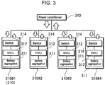
- FIG. 3 if a plurality of power supply units are connected to a single power conditioner, the configuration is as shown in FIG. 3 .
- four power supply units 310 are connected to single power conditioner 340.
- Each power supply unit 310 includes unit controller (BMU) 312, switch 314, and battery aggregation 311.
- Power conditioner 340 receives SOP1 to SOP4 from power supply units 310#1 to 310#4, respectively, and calculates the possible charging and discharging power (herein after, referred to as a "total SOP") of all power supply units 310.
- battery conditions of the power supply units are not necessarily constant, and the degree of deterioration and the like of the power supply units have variations, which differences tend to become larger with the duration of use.
- the conditions of the secondary battery cells included in each of the power supply units have variations of characteristics among the power supply units, for example, an internal resistance, a voltage, an SOC (state of charge), a degree of degradation, a temperature, and the like, in addition, the variations of wiring resistances and the like, and current ratios among the power supply units are thus not equal. Therefore, there are current deviations occurring among the power supply units, which state is referred to as a power deviation.
- the charging and discharging control, of above power conditioner 340 in the configuration of FIG. 3 , based on the total SOP is based on the assumption that there is no power deviation occurring among power supply units 310. In other words, if a power deviation occurs among power supply units 310, the rating or the SOP can be exceeded in some power supply unit 310 if electric power suppression is based on the total SOP. In other words, if a power deviation occurs, POBn ⁇ SOPn may not hold in some cases. As a result, the power supply system can abnormally stop for a reason such as an abnormal current.
- the present invention has been made in view of the above background.
- One of objects of the present invention is to provide a power supply system and a power conditioner in which it is possible to appropriately control charging and discharging even if a power deviation occurs between power supply units in a power supply system using a plurality of power supply units.
- a power supply system can be configured to include: a plurality of power supply units; and a control system to which the power supply units are parallel connected.
- Each of the power supply units includes: a battery aggregation including a plurality of secondary battery cells serial and parallel connected, a unit controller that acquires battery information about electric power at which the battery aggregation is chargeable and dischargeable and that outputs the battery information to the control system; and a switch that switches connection and disconnection between the power supply unit and the control system.
- the control system includes: a power conditioner that is parallel connected to the plurality of power supply units and is connected to an external power system, and receives electric power from the power system and charges the power supply units with the received electric power, and receives electric power from the power supply units and discharges the received electric power to the power system; a master controller that collects the battery information output from the unit controller of each of the power supply units; and a system controller that communicates to the power conditioner electric power required to the power supply system as a power command.
- the power conditioner determines, according to the power command from the system controller, a working total power POBall, which is a summation of electric power at which each of the power supply units is charged and discharged, the power conditioner determines possible total power to be in a range that possible individual power of each of the power supply units is not exceeded.
- the possible total power is determined from the possible individual power, of each of the power supply units, determined based on the battery information detected by each of the unit controllers, collected by the master controller from each of the unit controllers.
- the power conditioner causes charging and discharging of each of the power supply units within the calculated working individual power
- the master controller can be configured to detect a power deviation between the power supply units and to send out the power deviation to the power conditioner.
- the above configuration enables appropriate adjustment of charging and discharging power.
- the master controller can be configured to detect the power deviation between the power supply units at a predetermined cycle or at a time when a change in electric power is detected, and to constantly suppress the working individual power equal to or smaller than individual maximum charging and discharging power (SOP), based on the detected power deviation.
- SOP maximum charging and discharging power
- each of the unit controllers can be configured to determine the possible individual power, based on the battery information of the battery aggregation connected to each of the unit controllers.
- the master controller can be configured to determine the working individual power, based on the possible individual power sent out from each of the unit controllers connected to the master controller.
- the master controller can be configured to calculate power deviation ratio DOBn of each of the power supply units, assuming that a ratio for power supply unit #m, which is one of power supply units #1 to #n and with which (n-th working individual power POBn)/(n-th possible individual power SOPn) is largest, is 1, where 1 ⁇ m ⁇ n.
- the power conditioner can be configured to turn off the switch of the power supply unit that is one of the power supply units and whose possible individual power has become 0.
- a control system can be configured such that each of the switches includes a charge switch and a discharge switch.
- the power conditioner turns off the charge switch of the power supply unit that is one of the power supply units and whose chargeable individual power has become 0, and the power conditioner turns off the discharge switch of the power supply unit that is one of the power supply units and whose dischargeable individual power has become 0.
- a control system is a control system for a power supply system in which a plurality of power supply units are parallel connected and in which charging and discharging of each of the power supply units is controlled
- the control system can be configured to include: a power conditioner that is parallel connected to a plurality of power supply units and is connected to an external power system, and receives electric power from the power system and charges the power supply units with the received electric power, and receives electric power from the power supply units and discharges the received electric power to the power system; a master controller that collects battery information having been output from each of the power supply units; and a system controller that communicates to the power conditioner electric power required to the power supply system as a power command.
- the power conditioner causes charging and discharging of each of the power supply units within working individual power, based on possible total power at which all the power supply units are chargeable and dischargeable.
- the possible total power is determined from possible individual power, of each of the power supply units, determined based on the battery information detected on each of the power supply units.
- the working individual power is determined based on a power deviation indicating a difference of a charging and discharging power between the power supply units.
- the above configuration makes it possible to perform charging and discharging control depending on the power deviation, and an unintended system failure can thus be avoided.
- a power control method of a power supply system is a power control method in a power supply system including a plurality of power supply units and a control system to which the plurality of power supply units are parallel connected, and the power control method can include the steps of: receiving, by the control system, electric power required to the power supply system as a power command; acquiring battery information about electric power at which a battery aggregation included in each of the power supply units is chargeable and dischargeable, and outputting the acquired battery information to the control system, wherein the battery aggregation includes a plurality of secondary battery cells serial or parallel connected; determining, based on the battery information of the power supply units: possible individual power indicating electric power at which each of the power supply units is chargeable and dischargeable; possible total power indicating electric power at which all the power supply units are chargeable and dischargeable; and a power deviation indicating a difference of charging and discharging power between the power supply units, determining, based on the determined possible individual power, the determined
- a plurality of elements may be formed of the same component, and a single component may serve as a plurality of elements.
- the function of a single component may be realized by a plurality of components in cooperation.
- a power supply system according to an exemplary embodiment of the present invention, an example is described in which the present invention is applied to a large-scale power storage device to be used for a natural energy power plant and the like such as solar power generation and wind-power generation.
- This power storage device once stores electric power generated by solar power generation or wind-power generation and then supplies the electric power to power system ES.
- FIG. 1 is a block diagram showing power supply system 1000 according to an exemplary embodiment of the present invention.
- Power supply system 1000 shown in this drawing includes a plurality of power supply units 10 and control system 100 to which these power supply units 10 are parallel connected.
- Control system 100 includes power conditioner 140, system controller 160, and master controller (M-BMU) 120.
- M-BMU master controller
- Each power supply unit 10 includes battery aggregation 11, unit controller (BMU) 12, and switch 14.
- BMU unit controller
- switch 14 In each battery aggregation 11, a plurality of battery modules 1 are series and parallel connected. Further, each battery module 1 is configured with a plurality of series and parallel connected secondary battery cells.
- Unit controller 12 is connected to battery aggregation 11 and acquires battery information relating to electric power at which battery aggregation 11 can be charged and discharged.
- Unit controller 12 is connected to master controller 120 and outputs the battery information.
- the battery information represents conditions of battery aggregations 11 (or battery modules or secondary battery cells constituting battery aggregations 11) included in power supply units 10, for example, internal resistances, voltages, currents, SOCs, degrees of degradation, temperatures, and the like.
- Switch 14 is a component for switching connection and disconnection between each power supply unit 10 and power conditioner 140.
- switch 14 is disposed between battery aggregation 11 and power conditioner 140 and is switched on and off by unit controller 12.
- Switch 14 may be separately disposed in a charging direction and in a discharging direction.
- the switch includes a charge switch and a discharge switch. Then, the power conditioner turns off the charge switch of a power supply unitwhose chargeable individual power has become 0, and turns off the discharge switch of a power supply unit whose dischargeable individual power has become 0, among the power supply units.
- control system 100 includes power conditioner 140, system controller 160, and master controller 120. Regarding these components, instead of preparing individual components as shown FIG. 1 , arbitrary components can be integrated into one body.
- Power conditioner 140 is parallel connected to switches 14 of power supply units 10. Further, power conditioner 140 is connected to a power system. Power conditioner 140 receives electric power from the power system to charge power supply units 10, and conversely receives electric power from power supply units 10 to discharge the electric power to the power system.
- System controller 160 is a component to communicate to power conditioner 140 electric power of charging and discharging required to power supply system 1000 as a power command.
- System controller 160 receives a power command value, for example, through communication with a high-order system or an external device. Alternatively, system controller 160 may be configured to autonomously generate a power command value.
- Master controller 120 is connected to unit controller 12 of each power supply unit 10 to collect information (battery information) about a battery condition of each power supply unit 10. Further, master controller 120 determines a possible total power SOPall at which all power supply units 10 can be charged and discharged on the basis of the collected battery information. On the basis of the possible total power determined by master controller 120, power conditioner 140 inputs and outputs electric power for charging and discharging, from and to power supply unit 10.
- system controller 160 communicates a power command to power conditioner 140.
- master controller 120 sends out the battery information from each of unit controllers 12 to power conditioner 140.
- Power conditioner 140 receives this information and determines a possible total power SOPall (hereinafter, also referred to as a "total SOP") at which all power supply units 10 can be charged and discharged on the basis of the battery information sent out from master controller 120.
- a working total power POBall (hereinafter, also referred to as a "total POB") is determined on the basis of the power deviation, where the working total power POBall is a summation of electric power at which each power supply unit 10 is charged and discharged, and charging and discharging are then performed on power supply units 10 at the total POB. Since the charging and discharging are performed at the total POB, a working individual power POBn, which is an individual charging and discharging power for each power supply unit 10, is determined (the power deviation will be described later in detail).
- the possible total power and the possible individual power may be determined by the master controller or the unit controller other than by power conditioner 140.
- the unit controller determines the possible individual power of the power supply unit on the basis of the battery information of the battery aggregation connected to the unit controller.
- unit controllers 12 of respective power supply units 10 calculate a possible individual power SOP1 of power supply unit 10#1, a possible individual power SOP2 of power supply unit 10#2, a possible individual power SOP3 of power supply unit 10#3, and a possible individual power SOP4 of power supply unit 10#4.
- the possible total power SOP is calculated by master controller 120.
- master controller 120 and unit controllers 12 control turning on and off of switches 14 such that, if the SOP is 0 or abnormality has occurred in one of power supply units 10, the one of power supply units 10 is separated from power conditioner 140. By this operation, even if certain power supply unit 10 stops or the SOPn has become 0, an appropriated power control operation is ensured.
- a chargeable and dischargeable maximum power is calculated for each power supply unit.
- the total SOP is calculated and is communicated to the power conditioner.
- Equation 1 holds appropriately when there is no power deviation occurring among the power supply units.
- the possible individual power of each power supply unit depends on a battery condition and is not necessarily constant. Therefore, among the power supply units, there occurs a variation in a possible individual power, in other words, a power deviation.
- POBn ⁇ SOPn may not hold for a certain power supply unit, and a rating or an individual SOP may be exceeded. In this case, there is a concern that the power supply system may stop due to an abnormal current or other causes.
- charging and discharging control is performed in view of such a power deviation.
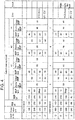
- FIG. 4 shows conditions of the battery modules at the time of the power control by which power supply units 310 are charged and discharged.
- condition numbers 1 to 8 there are differences in the power commands sent from system controller 160, and the battery conditions, possible individual power, and the like of the battery modules.
- condition numbers 1 to 4 there is no power deviation occurring among power supply units 310#1 to 310#4, in other words, the columns show the conditions of the battery modules in which a ratio of the possible individual power of power supply units 310 is 1:1:1:1.
- condition numbers 5 to 8 there are power deviations occurring among power supply units 310#1 to 310#4, and the columns show the conditions of the battery modules in which the current ratio of power supply units 310 is 5:4:4:3. Note that the power command and the total SOP are made to correspond to one another between condition numbers 1 to 4 and condition number 5 to 8.
- the power command sent from system controller 160 is 160 kW and is within the possible total power SOPall, and the working total power POBall can be 160 kW, which is the same as the power command. Therefore, this power command can be executed.
- the possible individual power SOP1 to SOP4 of power supply units 310 are each 60 kW for both of the discharging SOP and the charging SOP as described above, the working individual power of 40 kW can be dealt with, and POBn ⁇ SOPn thus holds.
- the power command is 240 kW
- the workable electric power POBall is similarly 240 kW
- each working individual power is 60 kW.
- the possible individual power of each power supply unit 310 is 60 kW for both of the discharging SOP and the charging SOP, the working individual power of 60 kW can be dealt with, and POBn ⁇ SOPn thus holds.
- condition number 3 the possible individual power SOP of each of power supply units 310#2 to 310#4 is 60 kW for both of the charging SOP and the discharging SOP as is the case with condition numbers 1 and 2.
- the power command for charging is 240 kW
- the power command is greater than the possible total power SOPall; therefore, the working total power POBall is limited to 180 kW.
- condition number 4 regarding possible individual power SOP for each of power supply units 310#2 to 310#4, the charging SOP and the discharging SOP are both 60 kW as is the case with condition numbers 1 to 3, but power supply unit 310#1 is being charged with a constant current or is in a condition in which the charging power is set lower than other power supply units 310#2 to 310#4 because of some reason.
- the discharging SOP is 60 kW, but the charging SOP is 20 kW.
- the power command is 240 kW
- the power command is greater than the possible total power SOPall, and the working total power POBall is therefore limited to 80 kW.
- the discharging SOP of each power supply unit 310 is 60 kW
- the charging SOP of power supply unit 310#1 is 20 kW
- the charging SOP of each of power supply units 310#2 to 310#4 is 60 kW. Therefore, every power supply unit can deal with working individual power of 20 kW, and POBn ⁇ SOPn thus holds.
- the charging SOP and the discharging SOP are normally both at their maximums.
- condition numbers 5 to 8 in which the power deviations among power supply units 310#1 to 310#4 are represented by a current ratio of 5:4:4:3. Note that the power command, the total POB, the discharging SOP, and the charging SOP are made to correspond to one another between condition numbers 5 to 8 and condition numbers 1 to 4.
- the power command is 160 kW and is within the possible total power SOPall, the working total power POBall can be 160 kW, which is the same as the power command. Therefore, this power command can be executed.
- the working total power POBall is distributed based on the power deviation.
- the power command is 240 kW and is within the possible total power SOPall, the working total power POBall can be 240 kW, which is the same as the power command.
- POBn ⁇ SOPn holds for power supply units 310#2 to 310#4, but for power supply unit 310#1, the working individual power POB1 is 75 kW and exceeds 60 kW of the possible individual power SOP1; therefore, POBn ⁇ SOPn does not hold, and the rating is exceeded.
- condition number 7 regarding the possible individual power SOP of each of power supply units 310#2 to 310#4, the charging SOP and the discharging SOP are both 60 kW as is the case with condition number 3.
- power supply unit 310#1 is in a fully-charged condition or a condition in which charging is prohibited because of some reason; therefore, the discharging SOP is 60 kW, but the charging SOP is 0. Therefore, charging is possible, but power supply unit 310#1 is separated from the power supply system at the time of charging. Therefore, power supply unit 310#1 is not charged.
- the working total power POBall is limited to 180 kW.
- POBn ⁇ SOPn holds for power supply unit 310#4; however, for power supply units 310#2 and 310#3, although each of the possible individual power SOP2 and SOP3 is 60 kW, each of the working individual power POB2 and POB3 is 65 kW. As a result, POBn ⁇ SOPn does not hold at the time of charging, and the rating is exceeded.
- the power command is 240 kW
- the power command is greater than the possible total power SOPall, and the working total power POBall is therefore limited to 80 kW.
- POBn ⁇ SOPn holds for power supply units 310#2 to 310#4; however, for power supply units 310#1, although the possible individual power SOP1 is 20 kW, the working individual power POB1 is 25 kW. As a result, POBn ⁇ SOPn does not hold at the time of charging, and the rating is exceeded.
- the working total power POBall is determined on the basis of the power deviation, and then on the basis of the working individual power POBall, charging and discharging of each power supply unit is controlled. Specifically, a chargeable and dischargeable maximum power is calculated for each power supply unit. With this arrangement, the charging SOPn and the discharging SOPn of each power supply unit are calculated. In addition, a measurement is performed at an appropriate time to detect whether there is a power deviation occurring.
- a voltage and a current are continuously measured at an appropriate time to measure POBn/SOPn.
- the SOPn is a possible individual power of power supply unit n
- the POBn is a working individual power of power supply unit n.
- the power supply system calculates the total SOP (possible total power SOPall) from the SOPn, the POBn, and the power deviation information measured at an appropriate time, and the power supply system communicates the calculated total SOP to power conditioner 140.
- the power supply system communicates the calculated total SOP to power conditioner 140.
- following Equation 2 is calculated to obtain the total SOP.
- DOBn represents a normalized power deviation ratio.
- DOBn represents the ratio of the electric power of each of the power supply units and is normalized such that the ratio of power supply unit #m with which the above POBn/SOPn is largest is 1.
- the numeral n for the power supply unit with which the POBn/SOPn is largest is substituted by m.
- power supply unit #n is supposed to be separated from power conditioner 140 at the time when the SOPn becomes 0. If power supply unit #n is not separated, the total SOP needs to be set to 0.
- Power conditioner 140 follows the power command and suppresses electric power such that the charging and discharging power is kept not greater than the total SOP.
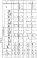
- condition numbers 1 to 8 are made to be identical to the examples represented by condition numbers 1 to 8 of FIG. 4 .
- condition numbers 1 to 4 show the case in which there is no power deviation occurring among power supply units 10#1 to 10#4 as is the case with condition numbers 1 to 4 of FIG. 4 and in which the discharging SOP and the charging SOP of power supply units 10 are each 1:1:1:1.
- condition number 1 regarding the possible individual power SOP of each of power supply units 10#1 to 10#4, the charging SOP and the discharging SOP are both 60 kW as is the case with condition number 1 of FIG. 4 , and the total POB (working total power POBall) is 160 kW.
- the total POB is 240 kW as is the case with condition number 1.
- Any of the working individual power POB2 to POB 4 can be dealt with by 60 kW of the charging SOP, and POBn ⁇ SOPn thus holds, resulting in the same situation as in the case of condition number 3 of FIG. 4 as a result.
- the total POB is 80 kW
- the possible individual power SOP of each of power supply units 10#2 to 10#4 is 60 kW for both of the charging SOP and the discharging SOP as is the case with condition numbers 1 to 3; however, since power supply unit 10#1 is being charged by constant voltage charging, the discharging SOP is 60 kW, and the charging SOP is 20 kW.
- Any of the working individual power can be dealt with by 20 kW and 60 kW of the charging SOP1 to SOP4, and POBn ⁇ SOPn thus holds, resulting in the same situation as in the case of condition number 4 of FIG. 4 as a result.
- condition numbers 5 to 8 in the case in which the power deviation of power supply units 10#1 to 10#4 is a current ratio of 5:4:4:3 as is the case with FIG. 5 .
- the power command, the total POB, the discharging SOP, and the charging SOP are made to correspond to one another between condition numbers 5 to 8 and condition numbers 1 to 4.
- condition number 6 regarding the possible individual power SOP of each of power supply units 10#1 to 10#4, the charging SOP and the discharging SOP are both 60 kW as is the case with condition number 2, and the total POB is 192 kW.
- each working individual power POBn can be dealt with, and POBn ⁇ SOPn thus holds.
- the working individual power of power supply unit 10#1 is lowered from 75 kW to 60 kW, and it is thus possible to prevent the possible individual power, that is, a maximum rated power from being exceeded, whereby the power supply system can stably operate.
- condition number 7 regarding the possible individual power SOP of each of power supply units 10#2 to 10#4, the charging SOP and the discharging SOP are both 60 kW as is the case with condition number 3; however, power supply unit 10#1 is fully charged, whereby the discharging SOP is 60 kW, and the charging SOP is 0. Therefore, charging is possible, but power supply unit 10#1 is separated from the power supply system at the time of charging. In addition, the total POB is 165 kW.
- the possible individual power SOP2 to SOP4 of each of power supply units 10 is 60 kW for both of the discharging SOP and the charging SOP as described above, each working individual power POBn can be dealt with, and POBn ⁇ SOPn thus holds.
- the working individual power of each of power supply units 10#2 and 10#3 is lowered from 65 kW to 60 kW, and it is thus possible to prevent the maximum rated power from being exceeded, whereby the power supply system can stably operate.
- condition number 8 the possible individual power SOP of each of power supply units 10#2 to 10#4 is 60 kW for both of the charging SOP and the discharging SOP, power supply unit 10#1 is being charged by constant voltage charging, the discharging SOP is 60 kW, and the charging SOP is 20 kW.
- the total POB is 64 kW.
- power supply unit 10 having maximum power deviation ratio dob_n is power supply unit 10#1.
- m 1
- the possible individual power SOP1 to SOP4 of power supply units 10 can respectively deal with working individual power POB1 to POB4, and POBn ⁇ SOPn thus holds.
- the working individual power of power supply unit 10#1 is lowered from 25 kW to 20 kW, and it is thus possible to prevent the maximum rated power from being exceeded, whereby the power supply system can stably operate.
- the power deviation can be detected at a constant cycle, and the working individual power can be updated on the basis of the detected power deviation.
- This arrangement enables appropriate adjustment of the charging and discharging power, coping with the battery condition temporally varying from hour to hour.
- the power deviation is preferably detected on the controller on the unit side and sent out to master controller 120.
- the present invention does not limit the timing of detection of the power deviation to a cyclic detection, and the detection can be performed at an arbitrary timing.
- the detection timing may be varied, for example, the detection may be performed at the time when an issue implying change in the power deviation occurs, or the detection may be performed at long intervals when the power deviation does not often change or at short intervals when the power deviation often changes.
- the method for measuring the power deviation and the like is not limited to the measurement of a voltage or a current, and other methods can be used appropriately.
- master controller 120 calculates the power deviation and communicates the power deviation to power conditioner 140; however, other than this configuration, the power deviation may be calculated by the system controller or the power conditioner. Alternatively, the function of calculating the power deviation may be provided on the unit controller side.
- unit controller 12' of power supply unit 10#1 includes the function of calculating the power deviation and plays a role of the master controller. In this case, the master controller does not need to be provided.
- a power supply system and a power conditioner according to the present invention can be suitably used as a large-scale power storage device used in a power plant or the like and as a controller of the power storage device.
Landscapes
- Engineering & Computer Science (AREA)
- Power Engineering (AREA)
- Charge And Discharge Circuits For Batteries Or The Like (AREA)
- Supply And Distribution Of Alternating Current (AREA)
Abstract
Description
- The present invention relates to a power supply system and a power conditioner.
- A power supply device including a number of serial and parallel connected secondary batteries is used as a power storage for peak cutting in home use, business facility use, factory use, and the like. Alternatively, the power supply device is used also in a power plant and the like. The peak cutting is performed to supply electric power in a time slot in which electric power consumption is at its peak (for example, around 1 pm to 4 pm) such that electric power is charged in the power supply device in the other time slots (for example, in the middle of the night) and the charged electric power is discharged at a peak time slot to supplement electric power at a peak time. In particular, in recent years, use of the natural energy represented by solar power generation and wind-power generation has been gathering attention; however, an electric source of these natural energies is not stable, and the power supply device is therefore used also in order to realize stable supply of electric power in a power system network by storing electric power temporarily in the power supply device in a power plant or a substation and by discharging the stored electric power.
- In such a power supply device, in order to store a large amount of electric power, a number of secondary batteries are connected to configure a modularized power supply device, and a plurality of power supply units are combined to structure a power supply system, so that increased electric power can be supplied (for example, see PTL 1). The power supply units in such a power supply system is managed by a high-order controller that totally manages the power supply units, and the overall power control is performed by a power conditioner. The power conditioner performs power control of each power supply unit such that the each power supply unit is charged and discharged.
- PTL 1: Unexamined Japanese Patent Publication No.
2010-092841 - However, the power supply system according to the background art has a problem that when there occurs a power deviation among the power supply units, the power control cannot be performed appropriately. For example, if only one power supply unit is used, the power conditioner communicates with the power supply unit on a one-on-one basis, and the power control of charging and discharging can be performed relatively easily.
-
FIG. 2 shows a power supply system in whichpower conditioner 240 controls charging and discharging power of onepower supply unit 210.Power supply unit 210 shown in this drawing includesswitch 214, unit controller (a battery management unit: hereinafter, referred to as a "BMU") 212 andbattery aggregation 211. Switch 214 is a component for switching between a connected state in whichpower supply unit 210 is connected topower conditioner 240 and a shut-off state in whichpower supply unit 210 is shut off at the time of abnormality or the like. BMU 212 is a component for monitoring a condition ofbattery aggregation 211. Further, BMU 212 communicates the condition of the battery aggregation topower conditioner 240. On the basis of the condition of the battery aggregation,power conditioner 240 determines the electric power of charging and discharging and communicates the electric power toBMU 212 ofpower supply unit 210 to perform charging and discharging. Here, the information communicated frompower supply unit 210 topower conditioner 240 includes possible charging and discharging power (a state of power: hereinafter, referred to as a "SOP"), which is maximum power at the time of communicating the information, andpower supply unit 210 can be charged and discharged at the maximum power. Regarding an example of the SOP communicated frompower supply unit 210 topower conditioner 240, the charging SOP is maximized whenpower supply unit 210 is constant-current charged, and the charging SOP is gradually decreased whenpower supply unit 210 is constant-voltage charged. Further, whenpower supply unit 210 becomes fully charged, the charging SOP is set to 0, and at the same time, the discharging SOP is maximized. In addition, whenpower supply unit 210 is completely discharged, the discharging SOP is set to 0, and the charging SOP is maximized. Further, ifpower supply unit 210 operates abnormally or is broken, the discharging SOP and the charging SOP are both set to 0. Further, whenbattery aggregation 211 is in a constant current (CC) charging and discharging region, the charging SOP and the discharging SOP are normally at their maximum. - On the other hand,
power conditioner 240 communicates a charging and discharging power command value (a power of battery: hereinafter, referred to as a "POB") topower supply unit 210 on the basis of a power command value from a high-order system or from outside, and the SOP. Thus, POB ≤ SOP is constantly satisfied. - As described above, if a number of
power supply units 210 connected topower conditioner 240 is one,power conditioner 240 communicates with the power supply unit on a one-on-one basis; therefore, the control of charging and discharging power can be relatively easily performed. In contrast, if a plurality of power supply units are connected to a single power conditioner, the configuration is as shown inFIG. 3 . In this example, fourpower supply units 310 are connected tosingle power conditioner 340. Eachpower supply unit 310 includes unit controller (BMU) 312,switch 314, andbattery aggregation 311. -
Power conditioner 340 receives SOP1 to SOP4 frompower supply units 310#1 to 310#4, respectively, and calculates the possible charging and discharging power (herein after, referred to as a "total SOP") of allpower supply units 310. Here, the total SOP is calculated by the following equation, supposing thatpower supply unit 310 satisfying SOP = 0 is to be separated frompower conditioner 340.
- With this total SOP used as an upper limit,
power conditioner 340 determines the total charging and discharging power (total POB) from the power command value and performs the charging and discharging onpower supply units 310 at electric power of the total POB. In this way,power conditioner 340 suppresses the electric power such that the electric power is kept equal to or smaller than the total SOP. With this arrangement, the electric power can be appropriately suppressed even in a case in which the SOP has become 0 for some reason, for example, in a case in which a certain power supply unit stops. Further, even if the SOP of a certain power supply unit becomes low, the electric power can be suppressed equal to or smaller than the minimum SOP. In other words, POBn ≤ SOPn holds. Note that power supply unit 301 satisfying SOP = 0 is supposed to be separated; however, in the case in which power supply unit 301 is not separated, POBn ≤ SOPn can be satisfied by setting the total SOP to 0. - However, battery conditions of the power supply units are not necessarily constant, and the degree of deterioration and the like of the power supply units have variations, which differences tend to become larger with the duration of use. Here, the conditions of the secondary battery cells included in each of the power supply units have variations of characteristics among the power supply units, for example, an internal resistance, a voltage, an SOC (state of charge), a degree of degradation, a temperature, and the like, in addition, the variations of wiring resistances and the like, and current ratios among the power supply units are thus not equal. Therefore, there are current deviations occurring among the power supply units, which state is referred to as a power deviation.
- The charging and discharging control, of
above power conditioner 340 in the configuration ofFIG. 3 , based on the total SOP is based on the assumption that there is no power deviation occurring amongpower supply units 310. In other words, if a power deviation occurs amongpower supply units 310, the rating or the SOP can be exceeded in somepower supply unit 310 if electric power suppression is based on the total SOP. In other words, if a power deviation occurs, POBn ≤ SOPn may not hold in some cases. As a result, the power supply system can abnormally stop for a reason such as an abnormal current. - The present invention has been made in view of the above background. One of objects of the present invention is to provide a power supply system and a power conditioner in which it is possible to appropriately control charging and discharging even if a power deviation occurs between power supply units in a power supply system using a plurality of power supply units.
- A power supply system according to a first aspect of the present invention can be configured to include: a plurality of power supply units; and a control system to which the power supply units are parallel connected. Each of the power supply units includes: a battery aggregation including a plurality of secondary battery cells serial and parallel connected, a unit controller that acquires battery information about electric power at which the battery aggregation is chargeable and dischargeable and that outputs the battery information to the control system; and a switch that switches connection and disconnection between the power supply unit and the control system. The control system includes: a power conditioner that is parallel connected to the plurality of power supply units and is connected to an external power system, and receives electric power from the power system and charges the power supply units with the received electric power, and receives electric power from the power supply units and discharges the received electric power to the power system; a master controller that collects the battery information output from the unit controller of each of the power supply units; and a system controller that communicates to the power conditioner electric power required to the power supply system as a power command. In a case where the power conditioner determines, according to the power command from the system controller, a working total power POBall, which is a summation of electric power at which each of the power supply units is charged and discharged, the power conditioner determines possible total power to be in a range that possible individual power of each of the power supply units is not exceeded. The possible total power is determined from the possible individual power, of each of the power supply units, determined based on the battery information detected by each of the unit controllers, collected by the master controller from each of the unit controllers. The power conditioner causes charging and discharging of each of the power supply units within the calculated working individual power
- With the above configuration, even in a situation in which there is a power deviation, POBn ≤ SOPn holds, the system does not stop, and an operation of charging and discharging can therefore be continued. This makes it possible to perform charging and discharging control depending on the power deviation, and an unintended system failure can thus be avoided.
- Further, in a power supply system according to a second aspect of the present invention, the master controller can be configured to detect a power deviation between the power supply units and to send out the power deviation to the power conditioner. The above configuration enables appropriate adjustment of charging and discharging power.
- Further, in a power supply system according to a third aspect of the present invention, the master controller can be configured to detect the power deviation between the power supply units at a predetermined cycle or at a time when a change in electric power is detected, and to constantly suppress the working individual power equal to or smaller than individual maximum charging and discharging power (SOP), based on the detected power deviation. The above configuration enables appropriate adjustment of the charging and discharging power, coping with the battery condition temporally varying from hour to hour. When it is measured by the above configuration at an appropriate time whether there is a power deviation occurring, it is possible to perform the charging and discharging control depending on the power deviation, and an unintended system failure can thus be avoided.
- Still further, in a power supply system according to a fourth aspect of the present invention, each of the unit controllers can be configured to determine the possible individual power, based on the battery information of the battery aggregation connected to each of the unit controllers.
- Still further, in a power supply system according to a fifth aspect of the present invention, the master controller can be configured to determine the working individual power, based on the possible individual power sent out from each of the unit controllers connected to the master controller.
- Still further, in a power supply system according to a sixth aspect of the present invention, the master controller can be configured to calculate power deviation ratio DOBn of each of the power supply units, assuming that a ratio for power supply unit #m, which is one of power
supply units # 1 to #n and with which (n-th working individual power POBn)/(n-th possible individual power SOPn) is largest, is 1, where 1 ≤ m ≤ n. - Still further, in a power supply system according to a seventh aspect of the present invention, the master controller can be configured to determine the possible total power by the following equation.

- Still further, in a power supply system according to an eighth aspect of the present invention, the power conditioner can be configured to turn off the switch of the power supply unit that is one of the power supply units and whose possible individual power has become 0. By separating a power supply unit whose SOP has become 0 from the power conditioner with the above configuration, the power supply unit can be protected from being overcharged or over-discharged.
- Still further, a control system according to a ninth aspect of the present invention can be configured such that each of the switches includes a charge switch and a discharge switch. The power conditioner turns off the charge switch of the power supply unit that is one of the power supply units and whose chargeable individual power has become 0, and the power conditioner turns off the discharge switch of the power supply unit that is one of the power supply units and whose dischargeable individual power has become 0.
- Still further, a control system according to a tenth aspect of the present invention is a control system for a power supply system in which a plurality of power supply units are parallel connected and in which charging and discharging of each of the power supply units is controlled, and the control system can be configured to include: a power conditioner that is parallel connected to a plurality of power supply units and is connected to an external power system, and receives electric power from the power system and charges the power supply units with the received electric power, and receives electric power from the power supply units and discharges the received electric power to the power system; a master controller that collects battery information having been output from each of the power supply units; and a system controller that communicates to the power conditioner electric power required to the power supply system as a power command. The power conditioner causes charging and discharging of each of the power supply units within working individual power, based on possible total power at which all the power supply units are chargeable and dischargeable. The possible total power is determined from possible individual power, of each of the power supply units, determined based on the battery information detected on each of the power supply units. The working individual power is determined based on a power deviation indicating a difference of a charging and discharging power between the power supply units.
- The above configuration makes it possible to perform charging and discharging control depending on the power deviation, and an unintended system failure can thus be avoided.
- Still further, a power control method of a power supply system according to an eleventh aspect of the present invention is a power control method in a power supply system including a plurality of power supply units and a control system to which the plurality of power supply units are parallel connected, and the power control method can include the steps of: receiving, by the control system, electric power required to the power supply system as a power command; acquiring battery information about electric power at which a battery aggregation included in each of the power supply units is chargeable and dischargeable, and outputting the acquired battery information to the control system, wherein the battery aggregation includes a plurality of secondary battery cells serial or parallel connected; determining, based on the battery information of the power supply units: possible individual power indicating electric power at which each of the power supply units is chargeable and dischargeable; possible total power indicating electric power at which all the power supply units are chargeable and dischargeable; and a power deviation indicating a difference of charging and discharging power between the power supply units, determining, based on the determined possible individual power, the determined possible total power, the determined power deviation, and the power command, working individual power in a range that the working individual power does not exceed the possible individual power of each of the power supply units, wherein the working individual power is electric power at which each power supply unit is charged and discharged.
- This makes it possible to perform charging and discharging control depending on the power deviation, and an unintended system failure can thus be avoided.
-
-
FIG. 1 is a block diagram showing a power supply system according to an exemplary embodiment of the present invention. -
FIG. 2 is a block diagram showing a power supply system in which a single power supply unit is connected to a single power conditioner. -
FIG. 3 is a block diagram showing a power supply system in which a plurality of power supply units are connected to a single power conditioner. -
FIG. 4 is a table showing conditions of each battery module ofFIG. 3 at a time of power control of each power supply unit. -
FIG. 5 is a table showing conditions of each battery module ofFIG. 1 at a time of power control of each power supply unit. -
FIG. 6 is a block diagram showing a power supply system according to a modified example. - An exemplary embodiment of the present invention is described below with reference to the drawings. However, the exemplary embodiment described below shows an example of the present invention, and the present invention is not limited to the following example. Further, in the present specification, components shown in the claims are not limited to the components of the exemplary embodiment. In particular, it is not intended to limit the sizes, materials, and shapes of components and relative arrangement between the components, which are described in the exemplary embodiment, to the scope of the present invention unless otherwise specified. The sizes and the like are mere explanation examples. However, the sizes and the positional relation of the components in each drawing are exaggerated for clearing the explanation in some cases. Furthermore, in the following description, the same names or the same reference marks denote the same components or the same types of components, and detailed description is therefore appropriately omitted. Further, regarding the elements constituting the present invention, a plurality of elements may be formed of the same component, and a single component may serve as a plurality of elements. To the contrary, the function of a single component may be realized by a plurality of components in cooperation.
- Hereinafter, as an example of a power supply system according to an exemplary embodiment of the present invention, an example is described in which the present invention is applied to a large-scale power storage device to be used for a natural energy power plant and the like such as solar power generation and wind-power generation. This power storage device once stores electric power generated by solar power generation or wind-power generation and then supplies the electric power to power system ES.
-
FIG. 1 is a block diagram showingpower supply system 1000 according to an exemplary embodiment of the present invention.Power supply system 1000 shown in this drawing includes a plurality ofpower supply units 10 andcontrol system 100 to which thesepower supply units 10 are parallel connected.Control system 100 includespower conditioner 140,system controller 160, and master controller (M-BMU) 120. - Each
power supply unit 10 includesbattery aggregation 11, unit controller (BMU) 12, andswitch 14. In eachbattery aggregation 11, a plurality ofbattery modules 1 are series and parallel connected. Further, eachbattery module 1 is configured with a plurality of series and parallel connected secondary battery cells. -
Unit controller 12 is connected tobattery aggregation 11 and acquires battery information relating to electric power at whichbattery aggregation 11 can be charged and discharged.Unit controller 12 is connected tomaster controller 120 and outputs the battery information. - Here, the battery information represents conditions of battery aggregations 11 (or battery modules or secondary battery cells constituting battery aggregations 11) included in
power supply units 10, for example, internal resistances, voltages, currents, SOCs, degrees of degradation, temperatures, and the like. -
Switch 14 is a component for switching connection and disconnection between eachpower supply unit 10 andpower conditioner 140. In the example ofFIG. 1 , switch 14 is disposed betweenbattery aggregation 11 andpower conditioner 140 and is switched on and off byunit controller 12.Switch 14 may be separately disposed in a charging direction and in a discharging direction. In this case, the switch includes a charge switch and a discharge switch. Then, the power conditioner turns off the charge switch of a power supply unitwhose chargeable individual power has become 0, and turns off the discharge switch of a power supply unit whose dischargeable individual power has become 0, among the power supply units. - On the other hand,
control system 100 includespower conditioner 140,system controller 160, andmaster controller 120. Regarding these components, instead of preparing individual components as shownFIG. 1 , arbitrary components can be integrated into one body. -
Power conditioner 140 is parallel connected toswitches 14 ofpower supply units 10. Further,power conditioner 140 is connected to a power system.Power conditioner 140 receives electric power from the power system to chargepower supply units 10, and conversely receives electric power frompower supply units 10 to discharge the electric power to the power system. -
System controller 160 is a component to communicate topower conditioner 140 electric power of charging and discharging required topower supply system 1000 as a power command.System controller 160 receives a power command value, for example, through communication with a high-order system or an external device. Alternatively,system controller 160 may be configured to autonomously generate a power command value. -
Master controller 120 is connected tounit controller 12 of eachpower supply unit 10 to collect information (battery information) about a battery condition of eachpower supply unit 10. Further,master controller 120 determines a possible total power SOPall at which allpower supply units 10 can be charged and discharged on the basis of the collected battery information. On the basis of the possible total power determined bymaster controller 120,power conditioner 140 inputs and outputs electric power for charging and discharging, from and topower supply unit 10. - In this
control system 100,system controller 160 communicates a power command topower conditioner 140. On the other hand,master controller 120 sends out the battery information from each ofunit controllers 12 topower conditioner 140.Power conditioner 140 receives this information and determines a possible total power SOPall (hereinafter, also referred to as a "total SOP") at which allpower supply units 10 can be charged and discharged on the basis of the battery information sent out frommaster controller 120. On the other hand, the power deviation amongpower supply units 10 is detected, and a working total power POBall (hereinafter, also referred to as a "total POB") is determined on the basis of the power deviation, where the working total power POBall is a summation of electric power at which eachpower supply unit 10 is charged and discharged, and charging and discharging are then performed onpower supply units 10 at the total POB. Since the charging and discharging are performed at the total POB, a working individual power POBn, which is an individual charging and discharging power for eachpower supply unit 10, is determined (the power deviation will be described later in detail). - Note that the possible total power and the possible individual power may be determined by the master controller or the unit controller other than by
power conditioner 140. For example, the unit controller determines the possible individual power of the power supply unit on the basis of the battery information of the battery aggregation connected to the unit controller. In the example ofFIG. 1 ,unit controllers 12 of respectivepower supply units 10 calculate a possible individual power SOP1 ofpower supply unit 10#1, a possible individual power SOP2 ofpower supply unit 10#2, a possible individual power SOP3 ofpower supply unit 10#3, and a possible individual power SOP4 ofpower supply unit 10#4. On the basis of the thus calculated possible individual power ofpower supply units 10, the possible total power SOP is calculated bymaster controller 120. Further,master controller 120 andunit controllers 12 control turning on and off ofswitches 14 such that, if the SOP is 0 or abnormality has occurred in one ofpower supply units 10, the one ofpower supply units 10 is separated frompower conditioner 140. By this operation, even if certainpower supply unit 10 stops or the SOPn has become 0, an appropriated power control operation is ensured. - Here, a description is given to electric current control on the power supply unit in a power supply system according to the comparative example. In the power supply system relating to the comparative example, a chargeable and dischargeable maximum power is calculated for each power supply unit. Then, from the SOPn of each power supply unit, the total SOP is calculated and is communicated to the power conditioner. For example, the possible total power SOP can be expressed by the following equation, where a number of the connected power supply units is n.

- With this arrangement, even when the possible individual power SOP of a certain power supply unit becomes low, the electric power can be kept to the minimum SOP or smaller. In other words, with respect to each power supply unit, POBn ≤ SOPn holds.
-
Equation 1 holds appropriately when there is no power deviation occurring among the power supply units. However, in practice, the possible individual power of each power supply unit depends on a battery condition and is not necessarily constant. Therefore, among the power supply units, there occurs a variation in a possible individual power, in other words, a power deviation. As a result, in the power control based on the above-described total SOP, POBn ≤ SOPn may not hold for a certain power supply unit, and a rating or an individual SOP may be exceeded. In this case, there is a concern that the power supply system may stop due to an abnormal current or other causes. To address this issue, in the present exemplary embodiment, charging and discharging control is performed in view of such a power deviation. - Here, in order to describe a problem caused by a power deviation, a discussion is made on a power supply system as the power supply system relating to the comparative example, in which four
power supply units 310#1 to 310#4 are connected tocommon power conditioner 340 as shown inFIG. 3 .FIG. 4 shows conditions of the battery modules at the time of the power control by whichpower supply units 310 are charged and discharged. In this table, amongcondition numbers 1 to 8, there are differences in the power commands sent fromsystem controller 160, and the battery conditions, possible individual power, and the like of the battery modules. In the upper columns ofFIG. 4 (condition numbers 1 to 4), there is no power deviation occurring amongpower supply units 310#1 to 310#4, in other words, the columns show the conditions of the battery modules in which a ratio of the possible individual power ofpower supply units 310 is 1:1:1:1. On the other hand, in the lower columns ofFIG. 4 (condition numbers 5 to 8), there are power deviations occurring amongpower supply units 310#1 to 310#4, and the columns show the conditions of the battery modules in which the current ratio ofpower supply units 310 is 5:4:4:3. Note that the power command and the total SOP are made to correspond to one another betweencondition numbers 1 to 4 andcondition number 5 to 8. - In
FIG. 4 , for example, in the case ofcondition number 1, with respect to the possible individual power SOP1 to SOP4 ofpower supply units 310#1 to 310#4, a dischargeable individual power SOP representing a dischargeable electric power (hereinafter, also referred to as a "discharging SOP") and a chargeable individual power SOP (hereinafter, also referred to as a "charging SOP ") representing chargeable electric power are both 60 kW. Therefore, the minimum SOP of SOPn is calculated to be 60 kW according toEquation 1, and a possible total power SOPall for allpower supply units 310#1 to 310#4 is 60 kW × 4 = 240 kW for both of discharging and charging. In addition, the power command sent fromsystem controller 160 is 160 kW and is within the possible total power SOPall, and the working total power POBall can be 160 kW, which is the same as the power command. Therefore, this power command can be executed. Further, the working individual power of eachpower supply unit 310 is 160 kW × 1/4 = 40 kW. Here, since the possible individual power SOP1 to SOP4 ofpower supply units 310 are each 60 kW for both of the discharging SOP and the charging SOP as described above, the working individual power of 40 kW can be dealt with, and POBn ≤ SOPn thus holds. - Similarly, in the case of
condition number 2, as is the case withcondition number 1, the possible total power SOPall is 60 kW × 4 = 240 kW for both of discharging and charging. In addition, since the power command is 240 kW, the workable electric power POBall is similarly 240 kW, and each working individual power is 60 kW. Here, since the possible individual power of eachpower supply unit 310 is 60 kW for both of the discharging SOP and the charging SOP, the working individual power of 60 kW can be dealt with, and POBn ≤ SOPn thus holds. - On the other hand, in the case of
condition number 3, the possible individual power SOP of each ofpower supply units 310#2 to 310#4 is 60 kW for both of the charging SOP and the discharging SOP as is the case withcondition numbers power supply unit 310#1 is in a fully-charged condition or in a condition in which charging is prohibited for some reason, and the discharging SOP and the charging SOP are respectively 60 kW and 0. Therefore, discharging is possible; however, at the time of charging, switch 14 is turned off to be separated frompower conditioner 140, andpower supply unit 310#1 is not charged. In this condition, the possible total power SOPall at the time of charging is 60 kW × 3 = 180 kW. Here, if the power command for charging is 240 kW, the power command is greater than the possible total power SOPall; therefore, the working total power POBall is limited to 180 kW. Further, regarding the working individual power of eachpower supply unit 310,power supply unit 310#1 is separated frompower conditioner 140 and is thus not an object of charging; the working individual power POB2 to POB4 ofpower supply units 310#2 to 310#4 each are 180 kW × (1/3) = 60 kW. - Moreover, in the case of
condition number 4, regarding possible individual power SOP for each ofpower supply units 310#2 to 310#4, the charging SOP and the discharging SOP are both 60 kW as is the case withcondition numbers 1 to 3, butpower supply unit 310#1 is being charged with a constant current or is in a condition in which the charging power is set lower than otherpower supply units 310#2 to 310#4 because of some reason. Thus, the discharging SOP is 60 kW, but the charging SOP is 20 kW. In this condition, since the minimum SOP at the time of charging is 20 kW, the possible total power SOPall is 20 kW × 4 = 80 kW according toEquation 1. Here, if the power command is 240 kW, the power command is greater than the possible total power SOPall, and the working total power POBall is therefore limited to 80 kW. In addition, the working individual power for charging each ofpower supply units 310#1 to 310#4 is 80 kW × 1/4 = 20 kW. On the other hand, regarding the possible individual power of eachpower supply unit 310, the discharging SOP of eachpower supply unit 310 is 60 kW, the charging SOP ofpower supply unit 310#1 is 20 kW, and the charging SOP of each ofpower supply units 310#2 to 310#4 is 60 kW. Therefore, every power supply unit can deal with working individual power of 20 kW, and POBn ≤ SOPn thus holds. Note that whenbattery aggregation 11 is in a constant current (CC) charging and discharging region, the charging SOP and the discharging SOP are normally both at their maximums. - As described above, in the condition in which there is no power deviation among
power supply units 310, charging and discharging power control can be appropriately performed in any of the cases ofcondition numbers 1 to 4. Next, a discussion is made oncondition numbers 5 to 8, in which the power deviations amongpower supply units 310#1 to 310#4 are represented by a current ratio of 5:4:4:3. Note that the power command, the total POB, the discharging SOP, and the charging SOP are made to correspond to one another betweencondition numbers 5 to 8 andcondition numbers 1 to 4. - First, in the case of
condition number 5, regarding the possible individual power SOP ofpower supply units 310#1 to 310#4, the charging SOP and the discharging SOP are both 60 kW as is the case withcondition number 1; therefore, the possible total power SOPall, which is a summation of the possible individual power SOP ofpower supply units 310#1 to 310#4, is calculated to be 60 kW × 4 = 240 kW according toEquation 1. In addition, since the power command is 160 kW and is within the possible total power SOPall, the working total power POBall can be 160 kW, which is the same as the power command. Therefore, this power command can be executed. Further, regarding the working individual power of each ofpower supply units 310, the working total power POBall is distributed based on the power deviation. Here, since the power deviation is 5:4:4:3, when 160 kW is distributed according to this ratio, the working individual power POB1 ofpower supply unit 310#1 is 160 kW × (5/16) = 50 kW, the working individual power POB2 ofpower supply unit 310#2 is 160 kW × (4/16) = 40 kW, the working individual power POB3 ofpower supply unit 310#3 is 160 kW × (4/16) = 40 kW, and the working individual power POB4 ofpower supply unit 310#4 is 160 kW × (3/16) = 30 kW. Since any working individual power POBn is within the charging SOP and the discharging SOP, POBn ≤ SOPn holds, and charging and discharging can thus be appropriately performed. - Next, in the case of
condition number 6, regarding the possible individual power SOP ofpower supply units 310#1 to 310#4, the charging SOP and the discharging SOP are both 60 kW as is the case withcondition number 2 andcondition number 5; therefore, the possible total power SOPall is 60 kW × 4 = 240 kW. In addition, since the power command is 240 kW and is within the possible total power SOPall, the working total power POBall can be 240 kW, which is the same as the power command. However, when the working individual power of each ofpower supply units 310 is distributed according to the power deviation, the working individual power POB1 ofpower supply unit 310#1 is 240 kW × (5/16) = 75 kW, the working individual power POB2 ofpower supply unit 310#2 is 240 kW × (4/16) = 60 kW, the working individual power POB3 ofpower supply unit 310#3 is 240 kW × (4/16) = 60 kW, and the working individual power POB4 ofpower supply unit 310#4 is 240 kW × (3/16) = 45 kW. In this case, POBn ≤ SOPn holds forpower supply units 310#2 to 310#4, but forpower supply unit 310#1, the working individual power POB1 is 75 kW and exceeds 60 kW of the possible individual power SOP1; therefore, POBn ≤ SOPn does not hold, and the rating is exceeded. - Further, in the case of condition number 7, regarding the possible individual power SOP of each of
power supply units 310#2 to 310#4, the charging SOP and the discharging SOP are both 60 kW as is the case withcondition number 3. However,power supply unit 310#1 is in a fully-charged condition or a condition in which charging is prohibited because of some reason; therefore, the discharging SOP is 60 kW, but the charging SOP is 0. Therefore, charging is possible, butpower supply unit 310#1 is separated from the power supply system at the time of charging. Therefore,power supply unit 310#1 is not charged. In this condition, the possible total power SOPall at the time of charging is 60 kW × 3 = 180 kW. Here, if the power command for charging is 240 kW, the power command exceeds the possible total power SOPall; therefore, the working total power POBall is limited to 180 kW. Further, regarding the working individual power of charging eachpower supply unit 310, sincepower supply unit 310#1 does not function because of being separated, the working individual power POB2 ofpower supply unit 310#2 is 180 kW × (4/16) = 65 kW, the working individual power POB3 ofpower supply unit 310#3 is 180 kW × (4/16) = 65 kW, and the working individual power POB4 ofpower supply unit 310#4 is 180 kW × (3/16) = 49kW. In this case, POBn ≤ SOPn holds forpower supply unit 310#4; however, forpower supply units 310#2 and 310#3, although each of the possible individual power SOP2 and SOP3 is 60 kW, each of the working individual power POB2 and POB3 is 65 kW. As a result, POBn ≤ SOPn does not hold at the time of charging, and the rating is exceeded. - Further, in the case of
condition number 8, regarding possible individual power SOP for each ofpower supply units 310#2 to 310#4, the charging SOP and the discharging SOP are both 60 kW, butpower supply unit 310#1 is being charged with a constant voltage or is in a condition in which the charging power is set lower than otherpower supply units 310#2 to 310#4 because of some reason. Therefore, the discharging SOP is 60 kW, but the charging SOP is 20 kW. In this condition, the possible total power SOPall at the time of charging is calculated to be 20 kW × 4 = 80 kW according toEquation 1. Here, if the power command is 240 kW, the power command is greater than the possible total power SOPall, and the working total power POBall is therefore limited to 80 kW. Further, regarding the working individual power of charging eachpower supply unit 310, the working individual power POB1 ofpower supply unit 310#1 is 80 kW × (5/16) = 25 kW, the working individual power POB2 ofpower supply unit 310#2 is 80 kW × (4/16) = 20 kW, the working individual power POB3 ofpower supply unit 310#3 is 80 kW × (4/16) = 20 kW, and the working individual power POB4 ofpower supply unit 310#4 is 80 kW × (3/16) = 15 kW. In this case, POBn ≤ SOPn holds forpower supply units 310#2 to 310#4; however, forpower supply units 310#1, although the possible individual power SOP1 is 20 kW, the working individual power POB1 is 25 kW. As a result, POBn ≤ SOPn does not hold at the time of charging, and the rating is exceeded. - As described above, if there is a power deviation, a problem can occur, for example, the power supply system abnormality stops due to an incident in which the rating is exceeded in a part of power supply units even under the same condition. To address this issue, in the present exemplary embodiment, the working total power POBall is determined on the basis of the power deviation, and then on the basis of the working individual power POBall, charging and discharging of each power supply unit is controlled. Specifically, a chargeable and dischargeable maximum power is calculated for each power supply unit. With this arrangement, the charging SOPn and the discharging SOPn of each power supply unit are calculated. In addition, a measurement is performed at an appropriate time to detect whether there is a power deviation occurring. Specifically, a voltage and a current are continuously measured at an appropriate time to measure POBn/SOPn. Here, as described above, the SOPn is a possible individual power of power supply unit n, and the POBn is a working individual power of power supply unit n.
- In the above-described manner, the power supply system calculates the total SOP (possible total power SOPall) from the SOPn, the POBn, and the power deviation information measured at an appropriate time, and the power supply system communicates the calculated total SOP to
power conditioner 140. In the present exemplary embodiment, followingEquation 2 is calculated to obtain the total SOP.

- In
above Equation 2, DOBn represents a normalized power deviation ratio. DOBn represents the ratio of the electric power of each of the power supply units and is normalized such that the ratio of power supply unit #m with which the above POBn/SOPn is largest is 1. The numeral n for the power supply unit with which the POBn/SOPn is largest is substituted by m. - Note that, as described above, power supply unit #n is supposed to be separated from
power conditioner 140 at the time when the SOPn becomes 0. If power supply unit #n is not separated, the total SOP needs to be set to 0. -
Power conditioner 140 follows the power command and suppresses electric power such that the charging and discharging power is kept not greater than the total SOP. With this configuration, in a situation in which there is a power deviation occurring, even when a certain power supply unit stops or the SOPn becomes 0, an appropriate electric power suppression can be performed. Further, even when the SOPn of a certain power supply unit decreases, it is possible to keep the electric power of the certain power supply unit not greater than the SOPn. In other words, it is possible to maintain the condition of POBn ≤ SOPn. As a result, even in a situation in which there is a power deviation occurring, the system does not stop, and an operation of charging and discharging can be continued. Here, a description is given, with reference toFIG. 5 , on an example in which charging and discharging control is performed, in the conditions corresponding toFIG. 4 , by a power control method according to the present exemplary embodiment. With reference toFIG. 5 , the power command, the discharging SOP, and the charging SOP ofcondition numbers 1 to 8 are made to be identical to the examples represented bycondition numbers 1 to 8 ofFIG. 4 . - Also in
FIG. 5 , the examples represented bycondition numbers 1 to 4 show the case in which there is no power deviation occurring amongpower supply units 10#1 to 10#4 as is the case withcondition numbers 1 to 4 ofFIG. 4 and in which the discharging SOP and the charging SOP ofpower supply units 10 are each 1:1:1:1. - First, in the case of
condition number 1, regarding the possible individual power SOP of each ofpower supply units 10#1 to 10#4, the charging SOP and the discharging SOP are both 60 kW as is the case withcondition number 1 ofFIG. 4 , and the total POB (working total power POBall) is 160 kW. Here, with respect to each ofpower supply units 10#1 to 10#4, power deviation ratio dob_n is calculated. Note that power deviation ratio dob_n is not normalized as the DOBn, and satisfies Σdob_n = 1. Regardingpower supply unit 10#1, dob_1 = POB1/SOP1 = 40 kW/(40 + 40 + 40 + 40) kW = 0.25, regardingpower supply unit 10#2, dob_2 = POB2/SOP2 = 40 kW/(40 + 40 + 40 + 40) kW = 0.25, regardingpower supply unit 10#3, dob_3 = POB3/SOP3 = 40 kW/(40+40+40+40) kW = 0.25, and regardingpower supply unit 10#4, dob_4 = POB4/SOP4 = 40 kW/(40 + 40 + 40 + 40) kW = 0.25. - Therefore, power deviation ratios dob_n for
power supply units 10#1 to 10#4 are the same, andpower supply unit 10 having maximum power deviation ratio dob_n is supposed here to bepower supply unit 10#1 (m = 1). Thus, when the total SOP (possible total power SOPall) is calculated according toEquation 2, total SOP = SOPm × (total POB)/POBm = SOP1 × (total POB)/POB1 = 60 kW × 160 kW/40 kW = 240 kW. Further, regarding the working individual power of eachpower supply unit 10, the working individual power POB1 ofpower supply unit 10#1 is 160 kW × dob_1 = 40 kW, the working individual power POB2 ofpower supply unit 10#2 is 160 kW × dob_2 = 40 kW, the working individual power POB3 ofpower supply unit 10#3 is 160 kW × dob_3 = 40 kW, and the working individual power POB4 ofpower supply unit 10#4 is 160 kW × dob_4 = 40 kW. Here, since the possible individual power SOP1 to SOP4 ofpower supply units 10 are each 60 kW for both of the discharging SOP and the charging SOP as described above, the working individual power of 40 kW can be dealt with, and POBn ≤ SOPn thus holds. As a result, the result is the same as in the case ofcondition number 1 ofFIG. 4 . - Similarly, in the case of
condition number 2, the possible total power SOPall is 60 kW × 4 = 240 kW for both of discharging and charging, and the total POB is 240 kW as is the case withcondition number 1. Further, power deviation ratios dob_n forpower supply units 10#1 to 10#4 are the same, andpower supply unit 10 having maximum power deviation ratio dob_n is also supposed here to bepower supply unit 10#1 (m = 1). Thus, the total SOP (possible total power SOPall) is calculated according toEquation 2, as total SOP = SOPm × (total POB)/POBm = SOP1 × (total POB)/POB1 = 60 kW × 240 kW/60 kW = 240 kW. Further, regarding the working individual power of eachpower supply unit 10, the working individual power POB1 ofpower supply unit 10#1 is 240 kW × dob_1 = 60 kW, the working individual power POB2 ofpower supply unit 10#2 is 240 kW × dob_2 = 60 kW, the working individual power POB3 ofpower supply unit 10#3 is 240 kW × dob_3 = 60 kW, and the working individual power POB4 ofpower supply unit 10#4 is 240 kW × dob_4 = 60 kW. Here, since the possible individual power SOP1 to SOP4 ofpower supply units 10 are each 60 kW for both of the discharging SOP and the charging SOP as described above, the working individual power of 60 kW can be dealt with, and POBn ≤ SOPn thus holds, resulting in the same situation as in the case ofcondition number 2 ofFIG. 4 as a result. - On the other hand, in the case of
condition number 3, the total POB is 180 kW, and the possible individual power SOP ofpower supply units 10#2 to 10#4 are each 60 kW for both of the charging SOP and the discharging SOP as is the case withcondition numbers power supply unit 10#1 is fully charged, the discharging SOP is 60 kW, and the charging SOP is 0. Therefore,power supply unit 10#1 can be discharged but is separated frompower conditioner 140 at the time of charging. Note that power deviation ratios dob_n forpower supply units 10#2 to 10#4 are the same, andpower supply unit 10 having maximum power deviation ratio dob_n is supposed here to bepower supply unit 10#2 (m = 2). In this condition, the possible total power SOPall at the time of charging is calculated according toEquation 2, as total SOP = SOPm × (total POB)/POBm = SOP2 × (total POB)/POB2 = 60 kW × 180 kW/60 kW = 180 kW. Further, regarding the working individual power of eachpower supply unit 10,power supply unit 10#1 is separated frompower conditioner 140 and is thus not taken into account, the working individual power POB2 ofpower supply unit 10#2 is 180 kW × dob_2 = 60 kW, the working individual power POB3 ofpower supply unit 10#3 is 180 kW × dob_3 = 60 kW, and the working individual power POB4 ofpower supply unit 10#4 is 180 kW × dob_4 = 60 kW. Any of the working individual power POB2 toPOB 4 can be dealt with by 60 kW of the charging SOP, and POBn ≤ SOPn thus holds, resulting in the same situation as in the case ofcondition number 3 ofFIG. 4 as a result. - Further, in the case of
condition number 4, the total POB is 80 kW, and the possible individual power SOP of each ofpower supply units 10#2 to 10#4 is 60 kW for both of the charging SOP and the discharging SOP as is the case withcondition numbers 1 to 3; however, sincepower supply unit 10#1 is being charged by constant voltage charging, the discharging SOP is 60 kW, and the charging SOP is 20 kW. Note that, regardingpower supply units 10#1 to 10#4, since power deviation ratios dob_n at the time of charging are the same, andpower supply unit 10 having maximum power deviation ratio dob_n is also supposed here to bepower supply unit 10#1 (m = 1). In this condition, the possible total power SOPall is calculated according toEquation 2, as total SOP = SOPm x (total POB)/POBm = SOP1 × (total POB)/POB1 = 20 kW × 80 kW/20 kW = 80 kW. Further, regarding the working individual power of eachpower supply unit 10, the working individual power POB1 ofpower supply unit 10#1 is 80 kW × dob_1 = 20 kW, the working individual power POB2 ofpower supply unit 10#2 is 80 kW × dob_2 = 20 kW, the working individual power POB3 ofpower supply unit 10#3 is 80 kW × dob_3 = 20 kW, and the working individual power POB4 ofpower supply unit 10#4 is 80 kW × dob_4 = 20 kW. Any of the working individual power can be dealt with by 20 kW and 60 kW of the charging SOP1 to SOP4, and POBn ≤ SOPn thus holds, resulting in the same situation as in the case ofcondition number 4 ofFIG. 4 as a result. - As described above, by the power control method according to the exemplary embodiment, also in the condition in which there is no power deviation among
power supply units 10, charging and discharging power control can be appropriately performed in any of the cases ofcondition numbers 1 to 4. Next, a discussion is made oncondition numbers 5 to 8 in the case in which the power deviation ofpower supply units 10#1 to 10#4 is a current ratio of 5:4:4:3 as is the case withFIG. 5 . Note that the power command, the total POB, the discharging SOP, and the charging SOP are made to correspond to one another betweencondition numbers 5 to 8 andcondition numbers 1 to 4. - First, in the case of
condition number 5, regarding the possible individual power SOP of each ofpower supply units 10#1 to 10#4, the charging SOP and the discharging SOP are both 60 kW as is the case withcondition number 1, and the total POB is 160 kW. Further, power deviation ratio dob_n calculated with respect to each ofpower supply units 10#1 to 10#4 is as follows: regardingpower supply unit 10#1, dob_1 = POB1/(total POB) = 50 kW/160 kW = 0.3125; regardingpower supply unit 10#2, dob_22 = POB2/(total POB) = 40 kW/160 kW = 0.25; regardingpower supply unit 10#3, dob_3 = POB3/(total POB) = 40 kW/160 kW = 0.25; and regardingpower supply unit 10#4, dob_4 = POB4/(total POB) = 30 kW/160 kW = 0.1875. Therefore,power supply unit 10 having maximum power deviation ratio dob_n ispower supply unit 10#1 (m = 1). Thus, when the total SOP (possible total power SOPall) is calculated according toEquation 2, total SOP = SOPm x (total POB)/POBm = SOP1 × (total POB)/POB1 = 60 kW × 160 kW/50 kW = 192 kW. Further, regarding the working individual power of eachpower supply unit 10, the working individual power POB1 ofpower supply unit 10#1 is 160 kW × dob_1 = 50 kW, the working individual power POB2 ofpower supply unit 10#2 is 160 kW × dob_2 = 40 kW, the working individual power POB3 ofpower supply unit 10#3 is 160 kW x dob_3 = 40 kW, and the working individual power POB4 ofpower supply unit 10#4 is 160 kW × dob_4 = 40 kW. Here, since the possible individual power SOP1 to SOP4 ofpower supply units 10 are each 60 kW for both of the discharging SOP and the charging SOP as described above, each working individual power POBn can be dealt with, and POBn ≤ SOPn thus holds. - Next, in the case of
condition number 6, regarding the possible individual power SOP of each ofpower supply units 10#1 to 10#4, the charging SOP and the discharging SOP are both 60 kW as is the case withcondition number 2, and the total POB is 192 kW. Further, power deviation ratio dob_n calculated with respect to each ofpower supply units 10#1 to 10#4 is as follows: regardingpower supply unit 10#1, dob_1 = POB1/(total POB) = 60 kW/192 kW = 0.3125; regardingpower supply unit 10#2, dob_2 = POB2/(total POB) = 48 kW/192 kW = 0.25; regardingpower supply unit 10#3, dob_3 = POB3/(total POB) = 48 kW/192 kW = 0.25; and regardingpower supply unit 10#4, dob_4 = POB4/(total POB) = 36 kW/192 kW = 0.1875. Therefore,power supply unit 10 having maximum power deviation ratio dob_n ispower supply unit 10#1 (m = 1). Thus, when the total SOP is calculated according toEquation 2, total SOP = SOPm × (total POB)/POBm = SOP1 × (total POB)/POB1 = 60 kW × 192 kW/60 kW = 192 kW. Further, regarding the working individual power of eachpower supply unit 10, the working individual power POB1 ofpower supply unit 10#1 is 192 kW × dob_1 = 60 kW, the working individual power POB2 ofpower supply unit 10#2 is 192 kW × dob_2 = 48 kW, the working individual power POB3 ofpower supply unit 10#3 is 192 kW × dob_3 = 48 kW, and the working individual power POB4 ofpower supply unit 10#4 is 192 kW x dob_4 = 36 kW. Here, since the possible individual power SOP1 to SOP4 ofpower supply units 10 are each 60 kW for both of the discharging SOP and the charging SOP as described above, each working individual power POBn can be dealt with, and POBn ≤ SOPn thus holds. Compared with the same condition inFIG. 4 , the working individual power ofpower supply unit 10#1 is lowered from 75 kW to 60 kW, and it is thus possible to prevent the possible individual power, that is, a maximum rated power from being exceeded, whereby the power supply system can stably operate. - Further, in the case of condition number 7, regarding the possible individual power SOP of each of
power supply units 10#2 to 10#4, the charging SOP and the discharging SOP are both 60 kW as is the case withcondition number 3; however,power supply unit 10#1 is fully charged, whereby the discharging SOP is 60 kW, and the charging SOP is 0. Therefore, charging is possible, butpower supply unit 10#1 is separated from the power supply system at the time of charging. In addition, the total POB is 165 kW. Here, power deviation ratio dob_n, at the time of charging, calculated with respect to each ofpower supply units 10#2 to 10#4 is as follows: regardingpower supply unit 10#2, dob_2 = POB2/(total POB) = 60 kW/165 kW = 0.3637; regardingpower supply unit 10#3, dob_3 = POB3/(total POB) = 60 kW/165 kW = 0.3637; and regardingpower supply unit 10#4, dob_4 = POB4/(total POB) = 45 kW/165 kW = 0.2728. Therefore,power supply unit 10 having maximum power deviation ratio dob_n ispower supply units 10#2 and 10#3. Here, when the total SOP at the time of charging is calculated according toEquation 2 assuming thatpower supply unit 10 having the maximum power deviation ispower supply unit 10#2 (m = 2), total SOP = SOPm × (total POB)/POBm = SOP2 × (total POB)/POB2 = 60 kW × 165 kW/60 kW = 165 kW. Further, regarding the working individual power, at the time of charging, of eachpower supply unit 10, the working individual power POB2 ofpower supply unit 10#2 is 165 kW × dob_2 = 60 kW, the working individual power POB3 ofpower supply unit 10#3 is 165 kW × dob_3 = 60 kW, and the working individual power POB4 ofpower supply unit 10#4 is 165 kW × dob_4 = 45 kW. Here, since the possible individual power SOP2 to SOP4 of each ofpower supply units 10 is 60 kW for both of the discharging SOP and the charging SOP as described above, each working individual power POBn can be dealt with, and POBn ≤ SOPn thus holds. Compared with the same condition inFIG. 4 , the working individual power of each ofpower supply units 10#2 and 10#3 is lowered from 65 kW to 60 kW, and it is thus possible to prevent the maximum rated power from being exceeded, whereby the power supply system can stably operate. - Further, in the case of
condition number 8, as is the case withcondition number 4, the possible individual power SOP of each ofpower supply units 10#2 to 10#4 is 60 kW for both of the charging SOP and the discharging SOP,power supply unit 10#1 is being charged by constant voltage charging, the discharging SOP is 60 kW, and the charging SOP is 20 kW. In addition, the total POB is 64 kW. Here, power deviation ratio dob_n, at the time of charging, calculated with respect to each ofpower supply units 10#1 to 10#4 is as follows: regardingpower supply unit 10#1, dob_1 = POB1/(total POB) = 20 kW/64 kW = 0.3125; regardingpower supply unit 10#2, dob_2 = POB2/(total POB) = 16 kW/64 kW = 0.25; regardingpower supply unit 10#3, dob_3 = POB3/(total POB) = 16 kW/64 kW =0.25; and regardingpower supply unit 10#4, dob_4 = POB4/(total POB) = 12 kW/64 kW = 0.1875. Therefore,power supply unit 10 having maximum power deviation ratio dob_n ispower supply unit 10#1. Thus, when the total SOP at the time of charging is calculated byEquation 2 where m = 1, the calculation result is total SOP = SOPm × (total POB)/POBm = SOP1 x (total POB)/POB1 = 20 kW × 64 kW/20 kW = 64 kW. Further, regarding the working individual power, at the time of charging, of eachpower supply unit 10, the working individual power POB1 ofpower supply unit 10#1 is 64 kW × dob_1 = 20 kW, the working individual power POB2 ofpower supply unit 10#2 is 64 kW × dob_2 = 16 kW, the working individual power POB3 ofpower supply unit 10#3 is 64 kW × dob_3 = 16 kW, and the working individual power POB4 ofpower supply unit 10#4 is 64 kW × dob_4 = 12 kW. Thus, the possible individual power SOP1 to SOP4 ofpower supply units 10 can respectively deal with working individual power POB1 to POB4, and POBn ≤ SOPn thus holds. Compared with the same condition inFIG. 4 , the working individual power ofpower supply unit 10#1 is lowered from 25 kW to 20 kW, and it is thus possible to prevent the maximum rated power from being exceeded, whereby the power supply system can stably operate. - By using the above method, it is possible to perform charging and discharging control depending on the power deviation, and an unintended system failure can thus be avoided.
- Note that the power deviation can be detected at a constant cycle, and the working individual power can be updated on the basis of the detected power deviation. This arrangement enables appropriate adjustment of the charging and discharging power, coping with the battery condition temporally varying from hour to hour. The power deviation is preferably detected on the controller on the unit side and sent out to
master controller 120. However, the present invention does not limit the timing of detection of the power deviation to a cyclic detection, and the detection can be performed at an arbitrary timing. For example, the detection timing may be varied, for example, the detection may be performed at the time when an issue implying change in the power deviation occurs, or the detection may be performed at long intervals when the power deviation does not often change or at short intervals when the power deviation often changes. Further, the method for measuring the power deviation and the like is not limited to the measurement of a voltage or a current, and other methods can be used appropriately. - Further, in the example of
FIG. 1 ,master controller 120 calculates the power deviation and communicates the power deviation topower conditioner 140; however, other than this configuration, the power deviation may be calculated by the system controller or the power conditioner. Alternatively, the function of calculating the power deviation may be provided on the unit controller side. For example, in a power supply system according to a modified example shownFIG. 6 , unit controller 12' ofpower supply unit 10#1 includes the function of calculating the power deviation and plays a role of the master controller. In this case, the master controller does not need to be provided. - A power supply system and a power conditioner according to the present invention can be suitably used as a large-scale power storage device used in a power plant or the like and as a controller of the power storage device.
-
- 1000
- power supply system
- 1
- battery module
- 10, 10#1 to 10#4, 210, 310, 310#1 to 310#4
- power supply unit
- 11, 211, 311
- battery aggregation
- 12, 12', 212, 312
- unit controller (BMU)
- 14, 214, 314
- switch
- 100
- control system
- 120
- master controller (M-BMU)
- 140, 240, 340
- power conditioner
- 160
- system controller
- ES
- power system
Claims (11)
- A power supply system comprising:a plurality of power supply units, and;a control system to which the power supply units are parallel connected,wherein each of the power supply units includes:a battery aggregation including a plurality of secondary battery cells serial and parallel connected;a unit controller that acquires battery information about electric power at which the battery aggregation is chargeable and dischargeable and that outputs the battery information to the control system; anda switch that switches connection and disconnection between the power supply unit and the control system,wherein the control system includes:a power conditioner that is parallel connected to the plurality of power supply units and is connected to an external power system, and receives electric power from the power system and charges the plurality of power supply units with the received electric power, and receives electric power from the plurality of power supply units and discharges the received electric power to the power system;a master controller that collects the battery information output from the unit controller of each of the power supply units; anda system controller that communicates to the power conditioner, electric power required to the power supply system as a power command, andwherein, in a case where the power conditioner determines, according to the power command from the system controller, a working total power POBall, which is a summation of electric power at which each of the power supply units is charged and discharged,the power conditioner determines possible total power to be in a range that possible individual power of each of the power supply units is not exceeded,the possible total power being determined from the possible individual power, of each of the power supply units, determined based on the battery information detected by each of the unit controllers, collected by the master controller from each of the unit controllers,the power conditioner causes charging and discharging of each of the power supply units within the calculated working individual power.
- The power supply system according to claim 1, wherein the master controller detects a power deviation between the power supply units and sends out the power deviation to the power conditioner.
- The power supply system according to claim 2, wherein the master controller detects the power deviation between the power supply units at a predetermined cycle or at a time when a change in electric power is detected, and constantly suppresses the working individual power equal to or smaller than individual maximum charging and discharging power, based on the detected power deviation.
- The power supply system according to any one of claims 1 to 3, wherein each of the unit controllers determines the possible individual power, based on the battery information of the battery aggregation connected to each of the unit controllers.
- The power supply system according to any one of claims 1 to 4, wherein the master controller determines the working individual power, based on the possible individual power sent out from each of the unit controllers connected to the master controller.
- The power supply system according to any one of claims 1 to 5, wherein the master controller calculates power deviation ratio DOBn of each of the power supply units, assuming that a ratio for power supply unit #m, which is one of power supply units #1 to #n and with which (n-th working individual power POBn)/(n-th possible individual power SOPn) is largest, is 1, where 1 ≤ m ≤ n.
- The power supply system according to claim 6, wherein
the master controller determines the possible total power by a following equation:
DOBn in above Equation 2 represents a power deviation ratio, wherein power deviation ratio DOBn of each of the power supply units is calculated, assuming that the ratio for power supply unit #m with which above POBn/SOPn is largest is 1, and n for the power supply unit with which the POBn/SOPn is largest is substituted by m. - The power supply system according to any one of claims 1 to 7, wherein the power conditioner turns off the switch of the power supply unit that is one of the power supply units and whose possible individual power has become 0.
- The power supply system according to any one of claims 1 to 8, wherein
each of the switches includes a charge switch and a discharge switch,
the power conditioner turns off the charge switch of the power supply unit that is one of the power supply units and whose chargeable individual power has become 0, and
the power conditioner turns off the discharge switch of the power supply unit that is one of the power supply units and whose dischargeable individual power has become 0. - A control system for a power supply system in which a plurality of power supply units are parallel connected and in which charging and discharging of each of the power supply units is controlled, the control system comprising:a power conditioner that is parallel connected to the plurality of power supply units and is connected to an external power system, and receives electric power from the power system and charges the plurality of power supply units with the received electric power, and receives electric power from the plurality of power supply units and discharges the received electric power to the power system;a master controller that collects battery information having been output from each of the power supply units; anda system controller that communicates to the power conditioner electric power required to the power supply system as a power command,wherein the power conditioner causes charging and discharging of each of the power supply units within working individual power, based on possible total power at which all the power supply units are chargeable and dischargeable, the possible total power being determined from a possible individual power, of each of the power supply units, determined based on the battery information detected on each of the power supply units, andthe working individual power being determined based on a power deviation indicating a difference of charging and discharging power between the power supply units.
- A power control method in a power supply system including a plurality of power supply units and a control system to which the plurality of power supply units are parallel connected, the power control method comprising:receiving, by the control system, electric power required to the power supply system as a power command;acquiring battery information about electric power at which a battery aggregation included in each of the power supply units is chargeable and dischargeable, and outputting the acquired battery information to the control system, the battery aggregation including a plurality of secondary battery cells serial or parallel connected;determining, based on the battery information of the power supply units:possible individual power indicating electric power at which each of the power supply units is chargeable and dischargeable;possible total power indicating electric power at which all the power supply units are chargeable and dischargeable; anda power deviation indicating a difference of a charging and discharging power between the power supply units, anddetermining, based on the determined possible individual power, the determined possible total power, the determined power deviation, and the power command, working individual power in a range that the working individual power does not exceed the possible individual power of each of the power supply units, the working individual power being electric power at which each power supply unit is charged and discharged.
Applications Claiming Priority (2)
| Application Number | Priority Date | Filing Date | Title |
|---|---|---|---|
| JP2016067790 | 2016-03-30 | ||
| PCT/JP2017/009698 WO2017169655A1 (en) | 2016-03-30 | 2017-03-10 | Power supply system, control system and power control method for power supply system |
Publications (3)
| Publication Number | Publication Date |
|---|---|
| EP3439132A1 true EP3439132A1 (en) | 2019-02-06 |
| EP3439132A4 EP3439132A4 (en) | 2019-03-13 |
| EP3439132B1 EP3439132B1 (en) | 2021-07-21 |
Family
ID=59963110
Family Applications (1)
| Application Number | Title | Priority Date | Filing Date |
|---|---|---|---|
| EP17774199.8A Active EP3439132B1 (en) | 2016-03-30 | 2017-03-10 | Power supply system, control system and power control method for power supply system |
Country Status (6)
| Country | Link |
|---|---|
| US (1) | US11862978B2 (en) |
| EP (1) | EP3439132B1 (en) |
| JP (1) | JP6790072B2 (en) |
| CN (1) | CN109121447B (en) |
| DK (1) | DK3439132T3 (en) |
| WO (1) | WO2017169655A1 (en) |
Families Citing this family (14)
| Publication number | Priority date | Publication date | Assignee | Title |
|---|---|---|---|---|
| CN110710050B (en) * | 2017-06-08 | 2023-02-17 | 松下知识产权经营株式会社 | Power storage system and management device |
| WO2018225416A1 (en) * | 2017-06-08 | 2018-12-13 | パナソニックIpマネジメント株式会社 | Electricity storage system and management device |
| CN108376989B (en) * | 2018-02-13 | 2022-07-26 | 中国电力科学研究院有限公司 | Battery energy storage power station partition control method and system based on multiple intelligent agents |
| JPWO2019208147A1 (en) * | 2018-04-23 | 2021-04-01 | 京セラ株式会社 | Power storage device, control device of power storage device, control method of power storage device |
| JP7573195B2 (en) * | 2019-07-18 | 2024-10-25 | パナソニックIpマネジメント株式会社 | Management device and power supply system |
| WO2021117902A1 (en) * | 2019-12-13 | 2021-06-17 | 本田技研工業株式会社 | Electricity storage device, vehicle, electricity storage device control method, and program |
| CN111559271A (en) * | 2020-06-08 | 2020-08-21 | 四川爱创科技有限公司 | Battery replacing cabinet system |
| JP7488605B2 (en) * | 2020-06-26 | 2024-05-22 | TeraWatt Technology株式会社 | Battery system, control device, and control method |
| CN116584028A (en) | 2020-09-28 | 2023-08-11 | 阿尔法能源技术公司 | Multiphase module-based energy system framework and related methods |
| KR102882635B1 (en) * | 2021-01-13 | 2025-11-05 | 주식회사 엘지에너지솔루션 | Apparatus and method for controlling power of battery bank |
| US20220368150A1 (en) * | 2021-04-27 | 2022-11-17 | China Energy Investment Corporation Limited | Voltage gradient-biased controller, system and method for controlling discharge of heterogeneous battery packs |
| US20220385076A1 (en) * | 2021-05-28 | 2022-12-01 | Deere & Company | Control system for managing battery cells with one or more dc-to-dc converters |
| US12500436B2 (en) * | 2021-10-20 | 2025-12-16 | China Energy Investment Corporation Limited | Controller, system, and method for managing discharge or charge of heterogeneous battery packs |
| US11652357B1 (en) * | 2021-10-27 | 2023-05-16 | China Energy Investment Corporation Limited | Controller, system and method for controlling discharge of heterogeneous battery packs |
Family Cites Families (22)
| Publication number | Priority date | Publication date | Assignee | Title |
|---|---|---|---|---|
| JP3872758B2 (en) * | 2003-01-08 | 2007-01-24 | 株式会社日立製作所 | Power control device |
| JP4921407B2 (en) * | 2008-03-27 | 2012-04-25 | 大阪瓦斯株式会社 | Power generation / air conditioning system |
| JP4469000B2 (en) | 2008-04-18 | 2010-05-26 | トヨタ自動車株式会社 | Power supply system, vehicle equipped with the same, and control method of power supply system |
| US20100028723A1 (en) | 2008-07-30 | 2010-02-04 | Chaz Haba | Power cell apparatus with three dimensional interconnect |
| CN102195310B (en) * | 2010-03-12 | 2014-11-05 | 株式会社东芝 | Combination battery unit and vehicle |
| EP2410602B1 (en) * | 2010-03-23 | 2014-11-26 | Nec Corporation | Charging and discharging method for lithium ion secondary batteries and charging and discharging system for the same |
| EP2462675A1 (en) * | 2010-08-23 | 2012-06-13 | Sanyo Electric Co., Ltd. | Power management system |
| WO2012043133A1 (en) | 2010-09-30 | 2012-04-05 | 三洋電機株式会社 | Storage battery charging/discharging control device and storage battery charging/discharging control method |
| JP5838313B2 (en) * | 2010-09-30 | 2016-01-06 | パナソニックIpマネジメント株式会社 | Storage battery charge / discharge control device and storage battery charge / discharge control method |
| CN103081281A (en) * | 2010-10-15 | 2013-05-01 | 三洋电机株式会社 | Power management system |
| WO2012050004A1 (en) | 2010-10-15 | 2012-04-19 | 三洋電機株式会社 | Power supply system |
| JPWO2012050014A1 (en) * | 2010-10-15 | 2014-02-24 | 三洋電機株式会社 | Power management system |
| JP5637878B2 (en) * | 2011-01-27 | 2014-12-10 | 株式会社日立製作所 | Secondary battery system |
| US8901894B2 (en) * | 2011-04-18 | 2014-12-02 | Renesas Electronics America Inc. | Battery management control method |
| JP5156112B2 (en) * | 2011-07-28 | 2013-03-06 | 三菱重工業株式会社 | Battery system |
| EP2843798B1 (en) * | 2012-04-26 | 2018-11-14 | Sekisui Chemical Co., Ltd. | Power storage system and cartridge |
| CN102848931A (en) * | 2012-09-14 | 2013-01-02 | 天津大学 | Energy source system structure of electric automobile |
| CN105324907B (en) * | 2013-06-20 | 2018-12-21 | 沃尔沃卡车集团 | Method for controlling an energy storage system |
| JP6125948B2 (en) * | 2013-08-12 | 2017-05-10 | 本田技研工業株式会社 | Non-contact charger |
| US10044200B2 (en) * | 2013-09-19 | 2018-08-07 | Toshiba Mitsubishi-Electric Industrial Systems Corporation | Storage battery system |
| JP6419809B2 (en) * | 2014-06-24 | 2018-11-07 | 株式会社東芝 | Power storage system and characteristic parameter estimation method |
| CN107615561B (en) * | 2015-05-18 | 2020-04-10 | 日产自动车株式会社 | Power storage device and connection control method |
-
2017
- 2017-03-10 DK DK17774199.8T patent/DK3439132T3/en active
- 2017-03-10 CN CN201780021109.5A patent/CN109121447B/en active Active
- 2017-03-10 JP JP2018508931A patent/JP6790072B2/en active Active
- 2017-03-10 EP EP17774199.8A patent/EP3439132B1/en active Active
- 2017-03-10 WO PCT/JP2017/009698 patent/WO2017169655A1/en not_active Ceased
- 2017-03-10 US US16/088,271 patent/US11862978B2/en active Active
Also Published As
| Publication number | Publication date |
|---|---|
| US11862978B2 (en) | 2024-01-02 |
| US20200303929A1 (en) | 2020-09-24 |
| EP3439132B1 (en) | 2021-07-21 |
| JPWO2017169655A1 (en) | 2019-03-14 |
| WO2017169655A1 (en) | 2017-10-05 |
| CN109121447B (en) | 2022-04-22 |
| DK3439132T3 (en) | 2021-08-16 |
| JP6790072B2 (en) | 2020-11-25 |
| CN109121447A (en) | 2019-01-01 |
| EP3439132A4 (en) | 2019-03-13 |
Similar Documents
| Publication | Publication Date | Title |
|---|---|---|
| US11862978B2 (en) | Power supply system, control system and power control method for power supply system | |
| US9401616B2 (en) | Battery pack, energy storage system including battery pack, and method of charging battery pack | |
| US10763682B2 (en) | Energy storage system and controlling method thereof | |
| US11063447B2 (en) | Battery pack and energy storage system comprising same | |
| EP2884575B1 (en) | Battery system and method of connecting battery module to a battery rack | |
| US10347952B2 (en) | Battery system | |
| US9300016B2 (en) | Battery system and energy storage system | |
| US9172259B2 (en) | Apparatus for managing battery, and energy storage system | |
| US9118191B2 (en) | Cell balancing method, cell balancing device, and energy storage system including the cell balancing device | |
| EP2490313B1 (en) | Energy storage system and controlling method thereof | |
| US9231407B2 (en) | Battery system, method of controlling the same, and energy storage system including the battery system | |
| EP2629388A1 (en) | Power management system | |
| KR101364094B1 (en) | Battery system and energy storage system including the same | |
| US9263776B2 (en) | Battery system and energy storage system including the same | |
| EP3148037A1 (en) | Energy storage system | |
| KR102415123B1 (en) | Battery Pack and Energy Storage System Including Thereof | |
| KR20150081731A (en) | Battery pack, energy storage system including the battery pack, and method of operating the battery pack | |
| CN103368219A (en) | Battery system and energy storage system | |
| KR20130049706A (en) | Apparatus for managing battery, method for balancing battery cells, and energy storage system | |
| US20130234517A1 (en) | Power accumulation system and method for controlling storage module | |
| dos Reis Marques et al. | Advanced Management System for Lithium-ion Batteries in Hybrid Inverters Optimized for Photovoltaic Systems Connected to the Grid |
Legal Events
| Date | Code | Title | Description |
|---|---|---|---|
| STAA | Information on the status of an ep patent application or granted ep patent |
Free format text: STATUS: THE INTERNATIONAL PUBLICATION HAS BEEN MADE |
|
| PUAI | Public reference made under article 153(3) epc to a published international application that has entered the european phase |
Free format text: ORIGINAL CODE: 0009012 |
|
| STAA | Information on the status of an ep patent application or granted ep patent |
Free format text: STATUS: REQUEST FOR EXAMINATION WAS MADE |
|
| 17P | Request for examination filed |
Effective date: 20180925 |
|
| AK | Designated contracting states |
Kind code of ref document: A1 Designated state(s): AL AT BE BG CH CY CZ DE DK EE ES FI FR GB GR HR HU IE IS IT LI LT LU LV MC MK MT NL NO PL PT RO RS SE SI SK SM TR |
|
| AX | Request for extension of the european patent |
Extension state: BA ME |
|
| A4 | Supplementary search report drawn up and despatched |
Effective date: 20190212 |
|
| RIC1 | Information provided on ipc code assigned before grant |
Ipc: H02J 3/32 20060101ALI20190206BHEP Ipc: H02J 7/00 20060101AFI20190206BHEP Ipc: H02J 7/02 20160101ALI20190206BHEP |
|
| DAV | Request for validation of the european patent (deleted) | ||
| DAX | Request for extension of the european patent (deleted) | ||
| GRAP | Despatch of communication of intention to grant a patent |
Free format text: ORIGINAL CODE: EPIDOSNIGR1 |
|
| STAA | Information on the status of an ep patent application or granted ep patent |
Free format text: STATUS: GRANT OF PATENT IS INTENDED |
|
| INTG | Intention to grant announced |
Effective date: 20210225 |
|
| GRAS | Grant fee paid |
Free format text: ORIGINAL CODE: EPIDOSNIGR3 |
|
| GRAA | (expected) grant |
Free format text: ORIGINAL CODE: 0009210 |
|
| STAA | Information on the status of an ep patent application or granted ep patent |
Free format text: STATUS: THE PATENT HAS BEEN GRANTED |
|
| AK | Designated contracting states |
Kind code of ref document: B1 Designated state(s): AL AT BE BG CH CY CZ DE DK EE ES FI FR GB GR HR HU IE IS IT LI LT LU LV MC MK MT NL NO PL PT RO RS SE SI SK SM TR |
|
| REG | Reference to a national code |
Ref country code: GB Ref legal event code: FG4D |
|
| REG | Reference to a national code |
Ref country code: CH Ref legal event code: EP |
|
| REG | Reference to a national code |
Ref country code: NL Ref legal event code: FP |
|
| REG | Reference to a national code |
Ref country code: DE Ref legal event code: R096 Ref document number: 602017042538 Country of ref document: DE |
|
| REG | Reference to a national code |
Ref country code: AT Ref legal event code: REF Ref document number: 1413499 Country of ref document: AT Kind code of ref document: T Effective date: 20210815 |
|
| REG | Reference to a national code |
Ref country code: DK Ref legal event code: T3 Effective date: 20210809 |
|
| REG | Reference to a national code |
Ref country code: IE Ref legal event code: FG4D |
|
| REG | Reference to a national code |
Ref country code: LT Ref legal event code: MG9D |
|
| REG | Reference to a national code |
Ref country code: AT Ref legal event code: MK05 Ref document number: 1413499 Country of ref document: AT Kind code of ref document: T Effective date: 20210721 |
|
| PG25 | Lapsed in a contracting state [announced via postgrant information from national office to epo] |
Ref country code: LT Free format text: LAPSE BECAUSE OF FAILURE TO SUBMIT A TRANSLATION OF THE DESCRIPTION OR TO PAY THE FEE WITHIN THE PRESCRIBED TIME-LIMIT Effective date: 20210721 Ref country code: AT Free format text: LAPSE BECAUSE OF FAILURE TO SUBMIT A TRANSLATION OF THE DESCRIPTION OR TO PAY THE FEE WITHIN THE PRESCRIBED TIME-LIMIT Effective date: 20210721 Ref country code: BG Free format text: LAPSE BECAUSE OF FAILURE TO SUBMIT A TRANSLATION OF THE DESCRIPTION OR TO PAY THE FEE WITHIN THE PRESCRIBED TIME-LIMIT Effective date: 20211021 Ref country code: FI Free format text: LAPSE BECAUSE OF FAILURE TO SUBMIT A TRANSLATION OF THE DESCRIPTION OR TO PAY THE FEE WITHIN THE PRESCRIBED TIME-LIMIT Effective date: 20210721 Ref country code: ES Free format text: LAPSE BECAUSE OF FAILURE TO SUBMIT A TRANSLATION OF THE DESCRIPTION OR TO PAY THE FEE WITHIN THE PRESCRIBED TIME-LIMIT Effective date: 20210721 Ref country code: PT Free format text: LAPSE BECAUSE OF FAILURE TO SUBMIT A TRANSLATION OF THE DESCRIPTION OR TO PAY THE FEE WITHIN THE PRESCRIBED TIME-LIMIT Effective date: 20211122 Ref country code: NO Free format text: LAPSE BECAUSE OF FAILURE TO SUBMIT A TRANSLATION OF THE DESCRIPTION OR TO PAY THE FEE WITHIN THE PRESCRIBED TIME-LIMIT Effective date: 20211021 Ref country code: SE Free format text: LAPSE BECAUSE OF FAILURE TO SUBMIT A TRANSLATION OF THE DESCRIPTION OR TO PAY THE FEE WITHIN THE PRESCRIBED TIME-LIMIT Effective date: 20210721 Ref country code: RS Free format text: LAPSE BECAUSE OF FAILURE TO SUBMIT A TRANSLATION OF THE DESCRIPTION OR TO PAY THE FEE WITHIN THE PRESCRIBED TIME-LIMIT Effective date: 20210721 Ref country code: HR Free format text: LAPSE BECAUSE OF FAILURE TO SUBMIT A TRANSLATION OF THE DESCRIPTION OR TO PAY THE FEE WITHIN THE PRESCRIBED TIME-LIMIT Effective date: 20210721 |
|
| PG25 | Lapsed in a contracting state [announced via postgrant information from national office to epo] |
Ref country code: PL Free format text: LAPSE BECAUSE OF FAILURE TO SUBMIT A TRANSLATION OF THE DESCRIPTION OR TO PAY THE FEE WITHIN THE PRESCRIBED TIME-LIMIT Effective date: 20210721 Ref country code: LV Free format text: LAPSE BECAUSE OF FAILURE TO SUBMIT A TRANSLATION OF THE DESCRIPTION OR TO PAY THE FEE WITHIN THE PRESCRIBED TIME-LIMIT Effective date: 20210721 Ref country code: GR Free format text: LAPSE BECAUSE OF FAILURE TO SUBMIT A TRANSLATION OF THE DESCRIPTION OR TO PAY THE FEE WITHIN THE PRESCRIBED TIME-LIMIT Effective date: 20211022 |
|
| REG | Reference to a national code |
Ref country code: DE Ref legal event code: R097 Ref document number: 602017042538 Country of ref document: DE |
|
| PLBE | No opposition filed within time limit |
Free format text: ORIGINAL CODE: 0009261 |
|
| STAA | Information on the status of an ep patent application or granted ep patent |
Free format text: STATUS: NO OPPOSITION FILED WITHIN TIME LIMIT |
|
| PG25 | Lapsed in a contracting state [announced via postgrant information from national office to epo] |
Ref country code: SM Free format text: LAPSE BECAUSE OF FAILURE TO SUBMIT A TRANSLATION OF THE DESCRIPTION OR TO PAY THE FEE WITHIN THE PRESCRIBED TIME-LIMIT Effective date: 20210721 Ref country code: SK Free format text: LAPSE BECAUSE OF FAILURE TO SUBMIT A TRANSLATION OF THE DESCRIPTION OR TO PAY THE FEE WITHIN THE PRESCRIBED TIME-LIMIT Effective date: 20210721 Ref country code: RO Free format text: LAPSE BECAUSE OF FAILURE TO SUBMIT A TRANSLATION OF THE DESCRIPTION OR TO PAY THE FEE WITHIN THE PRESCRIBED TIME-LIMIT Effective date: 20210721 Ref country code: EE Free format text: LAPSE BECAUSE OF FAILURE TO SUBMIT A TRANSLATION OF THE DESCRIPTION OR TO PAY THE FEE WITHIN THE PRESCRIBED TIME-LIMIT Effective date: 20210721 Ref country code: CZ Free format text: LAPSE BECAUSE OF FAILURE TO SUBMIT A TRANSLATION OF THE DESCRIPTION OR TO PAY THE FEE WITHIN THE PRESCRIBED TIME-LIMIT Effective date: 20210721 Ref country code: AL Free format text: LAPSE BECAUSE OF FAILURE TO SUBMIT A TRANSLATION OF THE DESCRIPTION OR TO PAY THE FEE WITHIN THE PRESCRIBED TIME-LIMIT Effective date: 20210721 |
|
| RAP4 | Party data changed (patent owner data changed or rights of a patent transferred) |
Owner name: PANASONIC HOLDINGS CORPORATION Owner name: SANYO ELECTRIC CO., LTD. |
|
| 26N | No opposition filed |
Effective date: 20220422 |
|
| PG25 | Lapsed in a contracting state [announced via postgrant information from national office to epo] |
Ref country code: IT Free format text: LAPSE BECAUSE OF FAILURE TO SUBMIT A TRANSLATION OF THE DESCRIPTION OR TO PAY THE FEE WITHIN THE PRESCRIBED TIME-LIMIT Effective date: 20210721 |
|
| PG25 | Lapsed in a contracting state [announced via postgrant information from national office to epo] |
Ref country code: MC Free format text: LAPSE BECAUSE OF FAILURE TO SUBMIT A TRANSLATION OF THE DESCRIPTION OR TO PAY THE FEE WITHIN THE PRESCRIBED TIME-LIMIT Effective date: 20210721 |
|
| GBPC | Gb: european patent ceased through non-payment of renewal fee |
Effective date: 20220310 |
|
| REG | Reference to a national code |
Ref country code: BE Ref legal event code: MM Effective date: 20220331 |
|
| REG | Reference to a national code |
Ref country code: NL Ref legal event code: HC Owner name: PANASONIC HOLDINGS CORPORATION; JP Free format text: DETAILS ASSIGNMENT: CHANGE OF OWNER(S), CHANGE OF OWNER(S) NAME; FORMER OWNER NAME: SANYO ELECTRIC CO., LTD. Effective date: 20221202 |
|
| REG | Reference to a national code |
Ref country code: DE Ref legal event code: R081 Ref document number: 602017042538 Country of ref document: DE Owner name: SANYO ELECTRIC CO., LTD., KADOMA-SHI, JP Free format text: FORMER OWNERS: PANASONIC CORPORATION, KADOMA-SHI, OSAKA, JP; SANYO ELECTRIC CO., LTD., KADOMA-SHI, OSAKA, JP Ref country code: DE Ref legal event code: R081 Ref document number: 602017042538 Country of ref document: DE Owner name: PANASONIC HOLDINGS CORPORATION, KADOMA-SHI, JP Free format text: FORMER OWNERS: PANASONIC CORPORATION, KADOMA-SHI, OSAKA, JP; SANYO ELECTRIC CO., LTD., KADOMA-SHI, OSAKA, JP Ref country code: DE Ref legal event code: R081 Ref document number: 602017042538 Country of ref document: DE Owner name: SANYO ELECTRIC CO., LTD., DAITO-SHI, JP Free format text: FORMER OWNERS: PANASONIC CORPORATION, KADOMA-SHI, OSAKA, JP; SANYO ELECTRIC CO., LTD., DAITO-SHI, OSAKA, JP Ref country code: DE Ref legal event code: R081 Ref document number: 602017042538 Country of ref document: DE Owner name: PANASONIC HOLDINGS CORPORATION, KADOMA-SHI, JP Free format text: FORMER OWNERS: PANASONIC CORPORATION, KADOMA-SHI, OSAKA, JP; SANYO ELECTRIC CO., LTD., DAITO-SHI, OSAKA, JP Ref country code: DE Ref legal event code: R081 Ref document number: 602017042538 Country of ref document: DE Owner name: PANASONIC ENERGY CO., LTD., MORIGUCHI-SHI, JP Free format text: FORMER OWNERS: PANASONIC CORPORATION, KADOMA-SHI, OSAKA, JP; SANYO ELECTRIC CO., LTD., KADOMA-SHI, OSAKA, JP |
|
| PG25 | Lapsed in a contracting state [announced via postgrant information from national office to epo] |
Ref country code: LU Free format text: LAPSE BECAUSE OF NON-PAYMENT OF DUE FEES Effective date: 20220310 Ref country code: IE Free format text: LAPSE BECAUSE OF NON-PAYMENT OF DUE FEES Effective date: 20220310 Ref country code: GB Free format text: LAPSE BECAUSE OF NON-PAYMENT OF DUE FEES Effective date: 20220310 Ref country code: FR Free format text: LAPSE BECAUSE OF NON-PAYMENT OF DUE FEES Effective date: 20220331 |
|
| PG25 | Lapsed in a contracting state [announced via postgrant information from national office to epo] |
Ref country code: BE Free format text: LAPSE BECAUSE OF NON-PAYMENT OF DUE FEES Effective date: 20220331 |
|
| REG | Reference to a national code |
Ref country code: NL Ref legal event code: PD Owner name: PANASONIC ENERGY CO., LTD.; JP Free format text: DETAILS ASSIGNMENT: CHANGE OF OWNER(S), ASSIGNMENT; FORMER OWNER NAME: SANYO ELECTRIC CO., LTD. Effective date: 20230925 |
|
| PG25 | Lapsed in a contracting state [announced via postgrant information from national office to epo] |
Ref country code: HU Free format text: LAPSE BECAUSE OF FAILURE TO SUBMIT A TRANSLATION OF THE DESCRIPTION OR TO PAY THE FEE WITHIN THE PRESCRIBED TIME-LIMIT; INVALID AB INITIO Effective date: 20170310 |
|
| PG25 | Lapsed in a contracting state [announced via postgrant information from national office to epo] |
Ref country code: MK Free format text: LAPSE BECAUSE OF FAILURE TO SUBMIT A TRANSLATION OF THE DESCRIPTION OR TO PAY THE FEE WITHIN THE PRESCRIBED TIME-LIMIT Effective date: 20210721 Ref country code: CY Free format text: LAPSE BECAUSE OF FAILURE TO SUBMIT A TRANSLATION OF THE DESCRIPTION OR TO PAY THE FEE WITHIN THE PRESCRIBED TIME-LIMIT Effective date: 20210721 |
|
| PG25 | Lapsed in a contracting state [announced via postgrant information from national office to epo] |
Ref country code: MT Free format text: LAPSE BECAUSE OF FAILURE TO SUBMIT A TRANSLATION OF THE DESCRIPTION OR TO PAY THE FEE WITHIN THE PRESCRIBED TIME-LIMIT Effective date: 20210721 |
|
| REG | Reference to a national code |
Ref country code: DE Ref legal event code: R081 Ref document number: 602017042538 Country of ref document: DE Owner name: PANASONIC ENERGY CO., LTD., MORIGUCHI-SHI, JP Free format text: FORMER OWNERS: PANASONIC HOLDINGS CORPORATION, KADOMA-SHI, OSAKA, JP; SANYO ELECTRIC CO., LTD., KADOMA-SHI, OSAKA, JP Ref country code: DE Ref legal event code: R081 Ref document number: 602017042538 Country of ref document: DE Owner name: PANASONIC HOLDINGS CORPORATION, KADOMA-SHI, JP Free format text: FORMER OWNERS: PANASONIC HOLDINGS CORPORATION, KADOMA-SHI, OSAKA, JP; SANYO ELECTRIC CO., LTD., KADOMA-SHI, OSAKA, JP |
|
| PG25 | Lapsed in a contracting state [announced via postgrant information from national office to epo] |
Ref country code: TR Free format text: LAPSE BECAUSE OF FAILURE TO SUBMIT A TRANSLATION OF THE DESCRIPTION OR TO PAY THE FEE WITHIN THE PRESCRIBED TIME-LIMIT Effective date: 20210721 |
|
| REG | Reference to a national code |
Ref country code: CH Ref legal event code: U11 Free format text: ST27 STATUS EVENT CODE: U-0-0-U10-U11 (AS PROVIDED BY THE NATIONAL OFFICE) Effective date: 20260401 |
|
| PGFP | Annual fee paid to national office [announced via postgrant information from national office to epo] |
Ref country code: DE Payment date: 20260319 Year of fee payment: 10 Ref country code: DK Payment date: 20260324 Year of fee payment: 10 |
|
| PGFP | Annual fee paid to national office [announced via postgrant information from national office to epo] |
Ref country code: NL Payment date: 20260319 Year of fee payment: 10 |
|
| PGFP | Annual fee paid to national office [announced via postgrant information from national office to epo] |
Ref country code: CH Payment date: 20260401 Year of fee payment: 10 |