EP3438915A1 - Work management system for construction machine, and construction machine - Google Patents
Work management system for construction machine, and construction machine Download PDFInfo
- Publication number
- EP3438915A1 EP3438915A1 EP17775188.0A EP17775188A EP3438915A1 EP 3438915 A1 EP3438915 A1 EP 3438915A1 EP 17775188 A EP17775188 A EP 17775188A EP 3438915 A1 EP3438915 A1 EP 3438915A1
- Authority
- EP
- European Patent Office
- Prior art keywords
- aircraft
- work
- construction machine
- progress
- camera
- Prior art date
- Legal status (The legal status is an assumption and is not a legal conclusion. Google has not performed a legal analysis and makes no representation as to the accuracy of the status listed.)
- Withdrawn
Links
Images




Classifications
-
- G—PHYSICS
- G05—CONTROLLING; REGULATING
- G05D—SYSTEMS FOR CONTROLLING OR REGULATING NON-ELECTRIC VARIABLES
- G05D1/00—Control of position, course, altitude or attitude of land, water, air or space vehicles, e.g. using automatic pilots
- G05D1/10—Simultaneous control of position or course in three dimensions
- G05D1/101—Simultaneous control of position or course in three dimensions specially adapted for aircraft
-
- B—PERFORMING OPERATIONS; TRANSPORTING
- B64—AIRCRAFT; AVIATION; COSMONAUTICS
- B64C—AEROPLANES; HELICOPTERS
- B64C13/00—Control systems or transmitting systems for actuating flying-control surfaces, lift-increasing flaps, air brakes, or spoilers
- B64C13/02—Initiating means
- B64C13/16—Initiating means actuated automatically, e.g. responsive to gust detectors
- B64C13/20—Initiating means actuated automatically, e.g. responsive to gust detectors using radiated signals
-
- B—PERFORMING OPERATIONS; TRANSPORTING
- B64—AIRCRAFT; AVIATION; COSMONAUTICS
- B64C—AEROPLANES; HELICOPTERS
- B64C39/00—Aircraft not otherwise provided for
- B64C39/02—Aircraft not otherwise provided for characterised by special use
- B64C39/024—Aircraft not otherwise provided for characterised by special use of the remote controlled vehicle type, i.e. RPV
-
- B—PERFORMING OPERATIONS; TRANSPORTING
- B64—AIRCRAFT; AVIATION; COSMONAUTICS
- B64D—EQUIPMENT FOR FITTING IN OR TO AIRCRAFT; FLIGHT SUITS; PARACHUTES; ARRANGEMENT OR MOUNTING OF POWER PLANTS OR PROPULSION TRANSMISSIONS IN AIRCRAFT
- B64D47/00—Equipment not otherwise provided for
- B64D47/08—Arrangements of cameras
-
- B—PERFORMING OPERATIONS; TRANSPORTING
- B64—AIRCRAFT; AVIATION; COSMONAUTICS
- B64U—UNMANNED AERIAL VEHICLES [UAV]; EQUIPMENT THEREFOR
- B64U10/00—Type of UAV
- B64U10/10—Rotorcrafts
- B64U10/13—Flying platforms
- B64U10/14—Flying platforms with four distinct rotor axes, e.g. quadcopters
-
- B—PERFORMING OPERATIONS; TRANSPORTING
- B64—AIRCRAFT; AVIATION; COSMONAUTICS
- B64U—UNMANNED AERIAL VEHICLES [UAV]; EQUIPMENT THEREFOR
- B64U20/00—Constructional aspects of UAVs
- B64U20/80—Arrangement of on-board electronics, e.g. avionics systems or wiring
- B64U20/87—Mounting of imaging devices, e.g. mounting of gimbals
-
- E—FIXED CONSTRUCTIONS
- E02—HYDRAULIC ENGINEERING; FOUNDATIONS; SOIL SHIFTING
- E02F—DREDGING; SOIL-SHIFTING
- E02F9/00—Component parts of dredgers or soil-shifting machines, not restricted to one of the kinds covered by groups E02F3/00 - E02F7/00
- E02F9/20—Drives; Control devices
-
- E—FIXED CONSTRUCTIONS
- E02—HYDRAULIC ENGINEERING; FOUNDATIONS; SOIL SHIFTING
- E02F—DREDGING; SOIL-SHIFTING
- E02F9/00—Component parts of dredgers or soil-shifting machines, not restricted to one of the kinds covered by groups E02F3/00 - E02F7/00
- E02F9/26—Indicating devices
-
- E—FIXED CONSTRUCTIONS
- E02—HYDRAULIC ENGINEERING; FOUNDATIONS; SOIL SHIFTING
- E02F—DREDGING; SOIL-SHIFTING
- E02F9/00—Component parts of dredgers or soil-shifting machines, not restricted to one of the kinds covered by groups E02F3/00 - E02F7/00
- E02F9/26—Indicating devices
- E02F9/261—Surveying the work-site to be treated
-
- G—PHYSICS
- G05—CONTROLLING; REGULATING
- G05D—SYSTEMS FOR CONTROLLING OR REGULATING NON-ELECTRIC VARIABLES
- G05D1/00—Control of position, course, altitude or attitude of land, water, air or space vehicles, e.g. using automatic pilots
- G05D1/0094—Control of position, course, altitude or attitude of land, water, air or space vehicles, e.g. using automatic pilots involving pointing a payload, e.g. camera, weapon, sensor, towards a fixed or moving target
-
- G—PHYSICS
- G06—COMPUTING OR CALCULATING; COUNTING
- G06Q—INFORMATION AND COMMUNICATION TECHNOLOGY [ICT] SPECIALLY ADAPTED FOR ADMINISTRATIVE, COMMERCIAL, FINANCIAL, MANAGERIAL OR SUPERVISORY PURPOSES; SYSTEMS OR METHODS SPECIALLY ADAPTED FOR ADMINISTRATIVE, COMMERCIAL, FINANCIAL, MANAGERIAL OR SUPERVISORY PURPOSES, NOT OTHERWISE PROVIDED FOR
- G06Q10/00—Administration; Management
- G06Q10/06—Resources, workflows, human or project management; Enterprise or organisation planning; Enterprise or organisation modelling
-
- G—PHYSICS
- G06—COMPUTING OR CALCULATING; COUNTING
- G06Q—INFORMATION AND COMMUNICATION TECHNOLOGY [ICT] SPECIALLY ADAPTED FOR ADMINISTRATIVE, COMMERCIAL, FINANCIAL, MANAGERIAL OR SUPERVISORY PURPOSES; SYSTEMS OR METHODS SPECIALLY ADAPTED FOR ADMINISTRATIVE, COMMERCIAL, FINANCIAL, MANAGERIAL OR SUPERVISORY PURPOSES, NOT OTHERWISE PROVIDED FOR
- G06Q50/00—Information and communication technology [ICT] specially adapted for implementation of business processes of specific business sectors, e.g. utilities or tourism
- G06Q50/08—Construction
-
- G—PHYSICS
- G06—COMPUTING OR CALCULATING; COUNTING
- G06Q—INFORMATION AND COMMUNICATION TECHNOLOGY [ICT] SPECIALLY ADAPTED FOR ADMINISTRATIVE, COMMERCIAL, FINANCIAL, MANAGERIAL OR SUPERVISORY PURPOSES; SYSTEMS OR METHODS SPECIALLY ADAPTED FOR ADMINISTRATIVE, COMMERCIAL, FINANCIAL, MANAGERIAL OR SUPERVISORY PURPOSES, NOT OTHERWISE PROVIDED FOR
- G06Q50/00—Information and communication technology [ICT] specially adapted for implementation of business processes of specific business sectors, e.g. utilities or tourism
- G06Q50/10—Services
-
- G—PHYSICS
- G08—SIGNALLING
- G08B—SIGNALLING SYSTEMS, e.g. PERSONAL CALLING SYSTEMS; ORDER TELEGRAPHS; ALARM SYSTEMS
- G08B13/00—Burglar, theft or intruder alarms
- G08B13/18—Actuation by interference with heat, light, or radiation of shorter wavelength; Actuation by intruding sources of heat, light, or radiation of shorter wavelength
- G08B13/189—Actuation by interference with heat, light, or radiation of shorter wavelength; Actuation by intruding sources of heat, light, or radiation of shorter wavelength using passive radiation detection systems
- G08B13/194—Actuation by interference with heat, light, or radiation of shorter wavelength; Actuation by intruding sources of heat, light, or radiation of shorter wavelength using passive radiation detection systems using image scanning and comparing systems
- G08B13/196—Actuation by interference with heat, light, or radiation of shorter wavelength; Actuation by intruding sources of heat, light, or radiation of shorter wavelength using passive radiation detection systems using image scanning and comparing systems using television cameras
- G08B13/19602—Image analysis to detect motion of the intruder, e.g. by frame subtraction
- G08B13/19608—Tracking movement of a target, e.g. by detecting an object predefined as a target, using target direction and or velocity to predict its new position
-
- G—PHYSICS
- G08—SIGNALLING
- G08B—SIGNALLING SYSTEMS, e.g. PERSONAL CALLING SYSTEMS; ORDER TELEGRAPHS; ALARM SYSTEMS
- G08B25/00—Alarm systems in which the location of the alarm condition is signalled to a central station, e.g. fire or police telegraphic systems
- G08B25/01—Alarm systems in which the location of the alarm condition is signalled to a central station, e.g. fire or police telegraphic systems characterised by the transmission medium
- G08B25/10—Alarm systems in which the location of the alarm condition is signalled to a central station, e.g. fire or police telegraphic systems characterised by the transmission medium using wireless transmission systems
-
- H—ELECTRICITY
- H04—ELECTRIC COMMUNICATION TECHNIQUE
- H04N—PICTORIAL COMMUNICATION, e.g. TELEVISION
- H04N7/00—Television systems
- H04N7/18—Closed-circuit television [CCTV] systems, i.e. systems in which the video signal is not broadcast
- H04N7/183—Closed-circuit television [CCTV] systems, i.e. systems in which the video signal is not broadcast for receiving images from a single remote source
- H04N7/185—Closed-circuit television [CCTV] systems, i.e. systems in which the video signal is not broadcast for receiving images from a single remote source from a mobile camera, e.g. for remote control
-
- B—PERFORMING OPERATIONS; TRANSPORTING
- B64—AIRCRAFT; AVIATION; COSMONAUTICS
- B64U—UNMANNED AERIAL VEHICLES [UAV]; EQUIPMENT THEREFOR
- B64U2101/00—UAVs specially adapted for particular uses or applications
- B64U2101/30—UAVs specially adapted for particular uses or applications for imaging, photography or videography
-
- B—PERFORMING OPERATIONS; TRANSPORTING
- B64—AIRCRAFT; AVIATION; COSMONAUTICS
- B64U—UNMANNED AERIAL VEHICLES [UAV]; EQUIPMENT THEREFOR
- B64U2101/00—UAVs specially adapted for particular uses or applications
- B64U2101/30—UAVs specially adapted for particular uses or applications for imaging, photography or videography
- B64U2101/31—UAVs specially adapted for particular uses or applications for imaging, photography or videography for surveillance
-
- B—PERFORMING OPERATIONS; TRANSPORTING
- B64—AIRCRAFT; AVIATION; COSMONAUTICS
- B64U—UNMANNED AERIAL VEHICLES [UAV]; EQUIPMENT THEREFOR
- B64U2201/00—UAVs characterised by their flight controls
-
- B—PERFORMING OPERATIONS; TRANSPORTING
- B64—AIRCRAFT; AVIATION; COSMONAUTICS
- B64U—UNMANNED AERIAL VEHICLES [UAV]; EQUIPMENT THEREFOR
- B64U2201/00—UAVs characterised by their flight controls
- B64U2201/20—Remote controls
Definitions
- the present invention relates to a construction machine work management system and a construction machine.
- Patent Document 1 An excavator that generates topographical information using trajectory information of a cutting edge of a bucket derived based on an output of a stroke sensor is known (see Patent Document 1).
- Patent Document 1 Japanese Unexamined Patent Publication No. 2014-129676
- the topographical information generated by the excavator described in Patent Document 1 does not reflect topographical changes that cannot be determined from the trajectory information of the cutting edge of the bucket, such as soil spilled from the bucket, soil that has crumbled naturally, and the like.
- a construction machine work management system that is capable of generating topographical information reflecting topographical changes that cannot be determined from trajectory information of a work element is desired.
- a construction machine work management system is configured by a construction machine, an aircraft equipped with a camera, and a management device.
- the construction machine work management system includes a progress region specifying unit configured to specify a progress region within a work site on which work progress has been made by the construction machine, and a flight path setting unit configured to set up a flight path of the aircraft so that the camera of the aircraft can capture an image of the progress region.
- a construction machine includes an attachment that is coated with a stress luminescent coating material.
- a construction machine work management system that is capable of generating topographical information reflecting topographical changes that cannot be determined from trajectory information of a work element may be provided.
- FIG. 1 is a schematic diagram showing an example configuration of the work management system SYS.
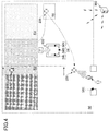
- FIG. 2 is a system configuration diagram of the work management system SYS.
- the work management system SYS is a system for managing work performed by an excavator using an aircraft, and is mainly configured by the excavator 100, the aircraft 200, and a management device 300.
- the number of the excavator 100 and the number of the aircraft 200 included in the work management system SYS may be one or plural.
- the work management system SYS includes one excavator 100 and one aircraft 200.
- the aircraft 200 is an autonomous aircraft that is capable of flying by remote control or automatically.
- Examples of the aircraft 200 include a multicopter (drone), an airship, and the like.
- a quadcopter equipped with a camera is used as the aircraft 200.
- the management device 300 is a device that manages work performed by the excavator 100, and may be implemented by a computer located outside a work site such as a management center, for example.
- the management device 300 may also be a portable computer that can be carried by a user, for example.
- the excavator 100 includes a lower travelling body 1 and an upper turning body 3 that is pivotally mounted on the lower travelling body 1 via a turning mechanism 2.
- a boom 4 is attached to the upper turning body 3.
- An arm 5 is attached to the tip of the boom 4, and a bucket 6 is attached to the tip of the arm 5.
- the boom 4, the arm 5, and the bucket 6 corresponding to work elements constitute an excavating attachment, which is an example of an attachment.
- the boom 4, the arm 5, and the bucket 6 are hydraulically driven by a boom cylinder 7, an arm cylinder 8, and a bucket cylinder 9, respectively.
- the upper turning body 3 includes a cabin 10 and a power source such as an engine 11.
- the excavator 100 includes the engine 11, a main pump 14, a pilot pump 15, a control valve 17, an operation device 26, a controller 30, an engine control device 74, and the like.
- the engine 11 is a driving source of the excavator 100 and may be implemented by a diesel engine that operates to maintain a predetermined rotational speed, for example.
- An output shaft of the engine 11 is connected to input shafts of the main pump 14 and the pilot pump 15.
- the main pump 14 is a swash-plate variable displacement hydraulic pump that supplies hydraulic oil to the control valve 17 via a hydraulic oil line 16.
- the discharge flow rate per rotation changes in accordance with a change in the swash plate tilt angle.
- the swash plate tilt angle is controlled by a regulator 14a.
- the regulator 14a changes the swash plate tilt angle in accordance with a change in the control current from the controller 30.
- the pilot pump 15 is a fixed displacement hydraulic pump that supplies hydraulic oil to various hydraulic control devices, such as the operation device 26, via a pilot line 25.
- the control valve 17 is a set of flow control valves for controlling the flow of hydraulic fluid with respect to hydraulic actuators.
- the control valve 17 can selectively supply hydraulic oil received from the main pump 14 through the hydraulic oil line 16 to one or more hydraulic actuators in accordance with a change in pilot pressure based on the operation direction and the operation amount of the operation device 26.
- the hydraulic actuators may include the boom cylinder 7, the arm cylinder 8, the bucket cylinder 9, a left travelling hydraulic motor 1A, a right travelling hydraulic motor 1B, and a turning hydraulic motor 2A, for example.
- the operation device 26 is a device used by the operator of the excavator 100 to operate the hydraulic actuators.
- the operation device 26 receives a supply of hydraulic fluid from the pilot pump 15 via the pilot line 25 and generates the pilot pressure.
- the pilot pressure is applied to a pilot port of a corresponding flow control valve through a pilot line 25a.
- the pilot pressure changes in accordance with the operation direction and the operation amount of the operation device 26.
- a pilot pressure sensor 15a detects the pilot pressure and outputs the detected value to the controller 30.
- the controller 30 is a control device for controlling the excavator 100.
- the controller 30 is implemented by a computer including a CPU, a RAM, a ROM, and the like.
- the CPU of the controller 30 reads programs corresponding to various functions from the ROM, loads the programs into the RAM, and executes the programs to thereby implementing functions corresponding to the programs.
- the engine control device 74 can control the engine 11.
- the engine control device 74 can control the fuel injection amount so that the engine 11 operates at the engine speed that has been set up via an input device.
- a transmitting device S1, a receiving device S2, a positioning device S3, a posture detecting device S4, an orientation detecting device S5, a camera S6, and a display device 40 that are attached to the upper turning body 3 are connected to the controller 30.
- the controller 30 can execute various computations based on information output by the receiving device S2, the positioning device S3, the posture detecting device S4, the orientation detecting device S5, and the camera S6.
- the controller 30 can then generate information based on the computation results and transmit the generated information to the exterior via the transmitting device S1 or display the generated information on the display device 40, for example.
- the transmitting device S1 can transmit information from the excavator 100 to the exterior.
- the transmitting device S1 may transmit information receivable by at least one of the aircraft 200 and the management device 300.
- the transmitting device S1 transmits information receivable by the management device 300 to the management device 300 in response to a request from the management device 300.
- the receiving device S2 can receive information from the exterior of the excavator 100.
- the receiving device S2 may receive information transmitted by at least one of the aircraft 200 and the management device 300.
- the receiving device S2 receives information transmitted from the management device 300.
- the positioning device S3 can acquire position information relating to the position of the excavator 100.
- the positioning device S3 is a GNSS (GPS) receiver that measures the latitude, longitude, and altitude of the excavator 100.
- GPS GPS
- the posture detecting device S4 can detect the posture of the excavator 100.
- the posture of the excavator 100 may be the posture of the excavating attachment, for example.
- the posture detecting device S4 includes a boom angle sensor, an arm angle sensor, a bucket angle sensor, and a machine frame tilt sensor.
- the boom angle sensor is a sensor that acquires the boom angle.
- the boom angle sensor may include a rotation angle sensor that detects the rotation angle of a boom foot pin, a stroke sensor that detects the stroke amount of the boom cylinder 7, a tilt (acceleration) sensor that detects the tilt angle of the boom 4, and the like.
- the boom angle sensor may also be a combination of an acceleration sensor and a gyro sensor, for example.
- the machine frame tilt sensor is a sensor that acquires the machine frame tilt angle of the excavator 100.
- the machine frame tilt sensor may detect the tilt angle of the upper turning body 3 with respect to the horizontal plane.
- the machine frame tilt sensor is a two-axis acceleration sensor that detects tilt angles around a longitudinal axis and a lateral axis of the upper turning body 3.
- the longitudinal axis and the lateral axis of the upper turning body 3 may intersect perpendicularly at a center point of the excavator 100 corresponding to a point on a turning axis of the excavator 100, for example.
- the machine frame tilt sensor may also be three-axis acceleration sensor, for example.
- the orientation detecting device S5 can detect the orientation of the excavator 100.
- the orientation detecting device S5 may include a geomagnetic sensor, a resolver or an encoder relating to the turning axis of the turning mechanism 2, and a gyro sensor, for example.
- the orientation detecting device S5 is implemented by a combination of a three-axis geomagnetic sensor and a gyro sensor.
- the controller 30 can acquire trajectory information of the tip of the bucket 6 based on outputs of the positioning device S3, the posture detecting device S4, and the orientation detecting device S5.
- the controller 30, the display device 40, the engine control device 74, and the like operate by receiving electric power supply from a storage battery 70.
- the storage battery 70 is charged by a generator 11a that is driven by the engine 11.
- the electric power of the storage battery 70 is also supplied to a starter 11b of the engine and the like.
- the starter 11b is driven by the electric power from the storage battery 70 to start the engine 11.
- the camera S6 is attached to the upper turning body 3 and is capable of capturing images of the periphery of the excavator 100.
- the camera S6 includes a backside camera for capturing an image of a space behind the excavator 100, a right side camera for capturing an image of a space on the right side of the excavator 100, and a left side camera for capturing an image of a space on the left side of the excavator 100.
- the display device 40 is a device for displaying various types of information and is arranged in the vicinity of the driver's seat in the cabin 10.
- the display device 40 can display an image captured by the camera S6 and an image captured by the aircraft 200.
- the image captured by the camera S6 includes a composite image obtained by combining captured images of a plurality of cameras.
- the composite image may be obtained using various image processing techniques such as viewpoint conversion processing and the like, for example.
- the aircraft 200 includes a control device 201, a transmitting device 202, a receiving device 203, an autonomous navigation device 204, a camera 205, a speaker 206, a microphone 207, and the like.
- the control device 201 is a device for controlling the aircraft 200.
- the control device 201 is implemented by a computer including a CPU, a RAM, a ROM, and the like.
- the CPU of the control device 201 can implement various functions corresponding to programs stored in the RAM by reading one or more of the programs from the ROM and loading the programs in the RAM to execute the programs.
- the transmitting device 202 can transmit information from the aircraft 200 to the exterior.
- the transmitting device 202 may transmit information receivable by at least one of the excavator 100 and the management device 300.
- the transmitting device 202 repeatedly transmits information receivable by the excavator 100 and the management device 300 at predetermined intervals.
- the information receivable by the excavator 100 and the management device 300 may include a captured image captured by the camera 205, for example.
- the receiving device 203 can receive information from the exterior of the aircraft 200.
- the receiving device 203 may receive information transmitted by the excavator 100 and information transmitted by the management device 300.
- the autonomous navigation device 204 is a device for enabling autonomous navigation of the aircraft 200.
- the autonomous navigation device 204 includes a flight control device, an electric motor, and a battery.
- the flight control device includes various sensors such as a gyro sensor, an acceleration sensor, a geomagnetic sensor (azimuth sensor), an atmospheric pressure sensor, a positioning sensor, an ultrasonic sensor, and the like to implement a posture maintaining function, an altitude maintaining function, and the like.
- the electric motor receives an electric power supply from the battery to rotate one or more propellers.
- the autonomous navigation device 204 may separately control the rotation speeds of four propellers and control the aircraft 200 to move along the flight path while maintaining the posture and altitude of the aircraft 200.
- the information relating to the flight path may include information on the latitude, longitude, and altitude of the flight position, for example.
- the control device 201 may acquire the information relating to the flight path from an external source via the receiving device 203, for example.
- the autonomous navigation device 204 may also change the orientation of the aircraft 200 upon receiving orientation information relating to the orientation from the control device 201, for example.
- the camera 205 is a device for capturing images.
- the camera 205 is attached to the aircraft 200 so that it can capture an image directly below the aircraft 200.
- a captured image captured by the camera 205 may include information on an image capturing position corresponding to the flight position of the aircraft 200, for example, and such information may be used to generate three-dimensional topographical data.
- the camera 205 may be a monocular camera or a stereo camera.
- the speaker 206 is a device that outputs audio to the exterior.
- the speaker 206 may be used to transmit audio information to a person at a work site, for example.
- the microphone 207 is a device that receives audio from the exterior.
- the microphone 207 may be used to acquire audio generated by a person at a work site, for example.
- the management device 300 includes a control device 301, a transmitting device 302, a receiving device 303, a display device 304, an operation input device 305, and the like.
- the control device 301 is a device for controlling the management device 300.
- the control device 301 may be implemented by a computer including a CPU, a RAM, a ROM, and the like.
- the CPU of the control device 301 can implement various functions corresponding to programs stored in the ROM by reading the programs from the ROM and loading the programs into the RAM to execute the programs.
- the transmitting device 302 can transmit information to the exterior of the management device 300.
- the transmitting device 302 may repeatedly transmit information receivable by the aircraft 200 at predetermined intervals.
- the transmitting device 302 may also transmit information receivable by the excavator, for example.
- the transmitting device 302 repeatedly transmits information receivable by the aircraft 200 at predetermined intervals.
- the information receivable by the aircraft 200 may include information relating to the flight path of the aircraft 200, for example.
- the receiving device 303 can receive information from the exterior of the management device 300.
- the receiving device 303 may receive information transmitted by at least one of the excavator 100 and the aircraft 200, for example.
- the receiving device 303 receives information transmitted by the aircraft 200.
- the information transmitted by the aircraft 200 may include a captured image captured by the camera 205 of the aircraft 200, for example.
- the display device 304 is a device for displaying various types of information.
- the display device 304 is a liquid crystal display that displays information relating to work performed by the excavator 100, information relating to topographical data, information relating to operation of the aircraft 200, and the like.
- the display device 304 may also display a captured image captured by the camera 205 of the aircraft 200, for example.
- the operation input device 305 is a device for receiving an operation input.
- the operation input device 305 is implemented by a touch panel arranged on a liquid crystal display.
- FIG. 3 is a functional block diagram of the work management system SYS.
- the work management system SYS mainly includes a trajectory information generating unit F1, an approaching object detecting unit F2, an authentication unit F3, a progress region specifying unit F4, a flight path setting unit F5, a topographical data generating unit F6, a work amount calculating unit F7, and a progress rate calculating unit F8.
- the controller 30 of the excavator 100 includes the trajectory information generating unit F1, the approaching object detecting unit F2, and the authentication unit F3, and the control device 301 of the management device 300 includes the progress region specifying unit F4, the flight path setting unit F5, the topographical data generating unit F6, the work amount calculating unit F7, and the progress rate calculating unit F8.
- each of the above functional elements may be included in either the controller 30 or the control device 301.
- the above functional elements may also be included in the control device 201 of the aircraft 200, for example.
- the trajectory information generating unit F1 can generate trajectory information relating to a trajectory followed by a predetermined portion of the attachment.
- the trajectory information generating unit F1 stores time series data of position information (latitude, longitude, and altitude) of the tip of the bucket 6 in a nonvolatile storage medium or the like as trajectory information relating to the trajectory followed by the tip of the bucket 6.
- the position information of the tip of the bucket 6 may be acquired based on outputs of the positioning device S3, the posture detecting device S4, and the orientation detecting device S5, for example.
- the approaching object detecting unit F2 can detect an object entering a predetermined region of the work site.
- An object may be a person, a dump, or the like.
- the approaching object detecting unit F2 detects a person entering a predetermined region of the work site by performing various image recognition processes on a captured image captured by the camera S6 attached to the excavator 100.
- the approaching object detecting unit F2 may also detect a person entering the predetermined region using a captured image captured by a camera installed at an entrance/exit gate of the work site or a captured image captured by the camera 205 of the aircraft 200, for example.
- the camera is connected to at least one of the excavator 100 and the management device 300 via wireless communication or the like.
- the authentication unit F3 can authenticate the entering person detected by the approaching object detecting unit F2.
- the entering person may be authenticated when the authentication unit F3 confirms that the entering person is a registered person based on a face image of the entering person included in the captured image of the camera S6 attached to the excavator 100.
- the captured image may also be a captured image captured by a camera installed at the entrance/exit gate of the work site or a captured image captured by the camera 205 of the aircraft 200, for example.
- the determination as to whether the entering person is a registered person may be implemented by the authentication unit F3 through machine learning by providing the authentication unit F3 with existing images of registered persons, such as photographs included in employee ID cards, for example.
- the authentication unit F3 may also authenticate the entering person using authentication methods other than face image authentication.
- Other authentication methods include, for example, card authentication or tag authentication using a card reader or an IC tag reader installed at the entrance/exit gate of the work site, pose authentication using image recognition to authenticate an entering person upon detecting that the entering user has taken a predetermined pose, and password authentication using audio recognition to authenticate an entering person upon detecting that the entering person has uttered a predetermined password, for example.
- the progress region specifying unit F4 can specify a progress region within the work site on which the excavator 100 has made work progress over a predetermined time period.
- the progress region specifying unit F4 specifies a progress region by determining a region passed by the tip of the bucket 6 since a last progress region was specified based on trajectory information generated after the last progress region was specified.
- the progress region may be specified using a plurality of sets of position information (latitude, longitude, and altitude) to derive its boundaries, for example.
- the flight path setting unit F5 can set up a flight path of the aircraft 200.
- the flight path setting unit F5 sets up the flight path of the aircraft 200 so that the camera 205 of the aircraft 200 can capture an image of the progress region specified by the progress region specifying unit F4.
- the flight path setting unit F5 sets up the flight path of the aircraft 200 so that the topographical data generating unit F6 can generate three-dimensional topographical data of the progress region based on the captured image captured by the camera 205.
- the flight path setting unit F5 may be configured to set up the flight path of the aircraft 200 so that the aircraft 200 directs itself toward the unauthenticated person, for example.
- the aircraft 200 may follow the flight path set up by the flight path setting unit F5 to fly from a parking lot into the sky above the unauthenticated person, for example. Then, the aircraft 200 may use the speaker 206 to output an audio message prompting the unauthenticated person to leave the predetermined region.
- the aircraft 200 may have the camera 205 capture an image to be used for face image authentication or pose authentication, for example.
- the aircraft 200 may use the speaker 206 to output an audio message prompting the unauthenticated person to utter a password for password authentication, for example.
- the aircraft 200 may operate the microphone 207 to collect the voice of the unauthenticated person uttering the password, for example.
- the aircraft 200 may return to the parking lot without outputting the audio message prompting the person to leave the predetermined region, for example.
- the topographical data generating unit F6 can generate three-dimensional topographical data of the work site.
- the topographical data generating unit F6 generates current three-dimensional topographical data of the current work site (work site under construction) based on three-dimensional topographical data of the work site before construction and three-dimensional topographical data of the progress region.
- the three-dimensional topographical data of the work site before construction may be generated based on total station survey measurements, GNSS survey measurements, or the like, for example.
- the three-dimensional topographical data of the work site before construction may also be generated based on an image of the entire work site captured by the camera 205 of the aircraft 200, for example.
- the topographical data generating unit F6 generates three-dimensional topographical data relating to a progress region based on an image of the progress region captured by the camera 205 of the aircraft 200.
- the topographical data generating unit F6 generates current three-dimensional topographical data of the current work site by joining the three-dimensional topographical data relating to the progress region and three-dimensional topographical data relating to regions other than the progress region.
- the three-dimensional topographical data of the work site before construction or three-dimensional topographical data previously generated by the topographical data generating unit F6 may be used as is as the three-dimensional topographical data relating to regions other than the progress region. This is because it can be presumed that regions other than the progress region remain unchanged.
- the topographical data generating unit F6 may generate the current three-dimensional topographical data of the current work site using three-dimensional topographical data relating to a plurality of progress regions generated by a plurality of excavators, for example.
- the topographical data generating unit F6 may be configured to refrain from generating three-dimensional topographical data relating to the part of the progress region at that time, for example. In such case, the topographical data generating unit F6 may reacquire an image of the part of the progress region at a different time to generate the three-dimensional topographical data relating to the part of the progress region, for example. This is to prevent the known object from being treated as part of the topography to thereby adversely affect calculation of the work amount, the progress rate, and the like.
- a message such as "work in progress” may be displayed at the same time, for example.
- information such as a flag indicating that generation of the three-dimensional topographical data relating to the part of the progress region is still in progress may be stored at the same time, for example.
- the topographical data generating unit F6 may be configured to refrain from calculating the work amount, the progress rate, and the like until an image of the part of the progress region is newly acquired, for example.
- a message such as "waiting for data acquisition" or the like may be displayed where the work amount, the progress rate, and the like should be displayed.
- a message indicating that the calculated values being displayed are provisional values may be displayed at the same time, for example.
- the work amount calculating unit F7 can calculate the work amount of the excavator 100 based on the three-dimensional topographical data of the work site. For example, the work amount calculating unit F7 may calculate the cumulative work amount of the excavator 100 after starting construction by deriving the volume of soil excavated from the difference between the three-dimensional topographical data of the work site before construction and the current three-dimensional topographical data of the current work site generated by the topographical data generating unit F6.
- the work amount calculating unit F7 may calculate the work amount of the excavator 100 over a period from a first time to a second time by deriving the volume of soil excavated during this time period from the difference between three-dimensional topographical data of the work site at the first time generated by the topographical data generating unit F6 and three-dimensional topographical data of the work site at the second time generated by the topographical data generating unit F6, for example.
- the progress rate calculating unit F8 can calculate the progress rate of work performed by the excavator 100 based on the three-dimensional topographical data of the work site. For example, the progress rate calculating unit F8 may calculate a value obtained by dividing the cumulative work amount of the excavator 100 by a target work amount as the progress rate.
- the target work amount may be obtained by deriving the volume of soil to be excavated from the difference between the three-dimensional topographical data of the work site before construction and three-dimensional topographical data of the work site when construction is completed (target topographical data), for example.
- the progress rate calculating unit F8 may calculate the progress rate of collaborative work performed by a plurality of excavators based on three-dimensional topographical data of the work site. For example, the progress rate calculating unit F8 may calculate a value obtained by dividing the total cumulative work amounts of the plurality of excavators by the target work amount as the progress rate of the collaborative work performed by the plurality of excavators.
- FIG. 4 is a top view of a work site R0 at the time work for the morning has been completed.
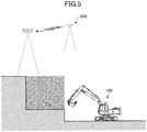
- FIG. 5 is a partial cross-sectional view of the work site R0 that represents a cross-sectional plane across the one dot chain line shown in FIG. 4 viewed from the direction of the arrows shown in FIG. 4 .
- region R1 represents a region that already has its topographical changes reflected in three-dimensional topographical data (e.g., region worked on yesterday) from among the regions that have been worked on by the exactor 100.
- Region R2 represents a region that does not yet have its topographical changes reflected in three-dimensional topographical data (e.g., region worked on this morning) from among the regions that have been worked on by the exactor 100.
- Region R3 represents a part of the regions that have not yet been worked on by the excavator 100 (e.g., region to be worked on this afternoon).
- Region R4 represents the parking lot for the aircraft 200.
- the ranges indicated by the broken lines in FIG. 5 represent image capturing ranges of the camera 205 of the aircraft 200.
- the control device 301 of the management device 300 determines whether the engine 11 of the excavator 100 has been stopped based on information transmitted by the excavator 100 and acquired via the receiving device 303.
- the progress region specifying unit F4 of the control device 301 specifies region R2 corresponding to the progress region within the work site R0 on which work progress was made by the excavator 100 this morning.
- the progress region specifying unit F4 acquires trajectory information stored by the trajectory information generating unit F1 of the controller 30 during operation of the excavator 100 and specifies region R2 based on the acquired trajectory information.
- the flight path setting unit F5 of the control device 301 sets up the flight path of the aircraft 200 so that the camera 205 of the aircraft 200 can capture an image of region R2 as the progress region specified by the progress region specifying unit F4. Then, the control device 301 transmits information relating to the flight path to the aircraft 200 via the transmitting device 302.
- the aircraft 200 Upon receiving the information relating to the flight path, the aircraft 200 flies from the parking lot into the sky above region R2 and captures an image of region R2 with the camera 205 while flying over the region R2 along the flight path. The aircraft 200 transmits the captured image to the management device 300 via the transmitting device 202.
- the topographical data generating unit F6 of the control device 301 generates three-dimensional topographical data relating to region R2 based on the image of region R2 captured by the camera 205 of the aircraft 200. Then, the topographical data generating unit F6 joins the three-dimensional topographical data relating to region R2 and three-dimensional topographical data relating to regions other than region R2 to generate the current three-dimensional topographical data of the current work site R0.
- the entering person monitoring function of the work management system SYS will be described with reference to FIG. 4 .
- the work management system SYS may use the aircraft 200 to prompt an unauthenticated person that has entered the work site R0 to leave.
- the approaching object detecting unit F2 of the controller 30 of the excavator 100 may detect a person entering a predetermined region within the work site R0 by implementing various image recognition processes on a captured image captured by the camera S6 attached to the excavator 100.
- the camera S6 includes a backside camera S6B, a left side camera S6L, and a right side camera S6R.
- the approaching object detecting unit F2 may also detect a person entering the work site R0 based on a captured image captured by a camera S6E installed at the entrance/exit gate of the work site R0, for example. In this case, the controller 30 acquires the captured image captured by the camera S6E via the transmitting device S1.
- the approaching object detecting unit F2 may be included in the control device 301 of the management device 300, for example.
- the control device 301 acquires the captured image captured by the camera S6E and the captured image captured by the camera S6 via the receiving device 303.
- detection of an approaching object may also be implemented using some other sensor such as an infrared sensor, an ultrasonic sensor, or the like.
- the authentication unit F3 of the controller 30 tries to authenticate the entering person detected by the approaching object detecting unit F2. If the entering person cannot be authenticated, the authentication unit F3 notifies the management device 300 to that effect. If the entering person could be successfully authenticated, the authentication unit F3 may omit the above notification to the management device 300.
- the management device 300 Upon receiving the notification that the entering person cannot be authenticated, the management device 300 directs the aircraft 200 to the entering person. Specifically, the flight path setting unit F5 of the control device 301 sets up the flight path of the aircraft 200 so that the aircraft 200 is directed to the unauthenticated person.
- the aircraft 200 Upon receiving information relating to the flight path set up by the flight path setting unit F5, the aircraft 200 flies from the parking lot toward the entering person and attempts to authenticate the entering person. For example, the aircraft 200 may use the speaker 206 to prompt the entering person to utter a password and authenticate the entering person if the microphone 207 can recognize the password uttered by the entering person. The aircraft 200 may also authenticate the entering person through pose authentication, for example.
- the aircraft 200 uses the speaker 206 to output an audio message prompting the entering person to leave the work site R0. If the entering person could be authenticated, the aircraft 200 may return to the parking lot without outputting such an audio message.
- the work management system SYS can efficiently and accurately manage work progress made by the excavator 100 based on a captured image captured by the camera 205 of the aircraft 200. Also, by generating three-dimensional topographical data using the camera 205 of the aircraft 200, total station surveying, GNSS surveying, or the like may be omitted, for example.
- the operation management system SYS generates three-dimensional topographical data by having the aircraft 200 capture an image of only a progress region within the work site R0 on which work progress was made by the excavator 100 over a predetermined time period, efficient work progress management may be achieved, for example.
- the work management system SYS can detect an object such as a person, a dump, or the like that has entered a predetermined region within the work site R0 and can notify an operator of the excavator 100 or an administrator at a management center to that effect, for example.
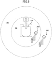
- FIG. 6 is a top view of the excavator 100 operating at a work site.
- FIG. 6 illustrates a first work range R5 represented by an annular region in between an outer dashed circle and an inner dashed circle, and a second work range R6 represented by a circular region within the inner dashed circle.
- the second work range R6 may correspond to the turning range of the excavator 100 (range that can be reached by the excavating attachment), for example.
- the authentication unit F3 of the controller 30 of the excavator 100 classifies one or more authenticated persons as either a related person (worker) that is involved in the work being performed or a non-related person that is not involved in the work.
- the controller 30 may notify the operator of the excavator 100 to that effect via an in-vehicle speaker or the display device 40 installed in the cabin 10, for example.
- the controller 30 When the approaching object detecting unit F2 detects that an authenticated person classified as a non-related person has entered the first work range R5, the controller 30 notifies the operator of the excavator 100 to the effect and also notifies the management device 300 to that effect via the transmitting device S1.
- the management device 300 Upon receiving the notification that a non-related person has entered the first work range R5, the management device 300 directs the aircraft 200 to the non-related person. Specifically, the flight path setting unit F5 of the control device 301 sets up the flight path of the aircraft 200 so that the aircraft 200 is directed to the non-related person.
- the aircraft 200 Upon receiving information relating to the flight path set up by the flight path setting unit F5, the aircraft 200 flies from the parking lot toward the non-related person and uses the speaker 206 to output an audio message prompting the non-related person to leave the first work range R5, for example.
- the controller 30 When the approaching object detecting unit F2 detects that an authenticated person classified as a related person has entered the second work range R6, the controller 30 notifies the operator of the excavator 100 to that effect via the in-vehicle speaker or the display device 40 installed in the cabin 10, for example. In this case, the controller 30 may notify the operator of the excavator 100 to that effect in a mode that is different from that used in the case where the related person has entered the first work range R5 (e.g., a different audio message, larger volume, larger display, or the like). Also, movement of the excavator 100 may be restricted, for example.
- the controller 30 When the approaching object detecting unit F2 detects that an authenticated person classified as a non-related person has entered the second work range R6, the controller 30 notifies the operator of the excavator 100 to that effect and also notifies the management device 300 to that effect via the transmitting device S1.
- the controller 30 may also use a speaker installed outside the cabin 10 to output an audio message prompting the non-related person to leave the second work range R6, for example.
- the management device 300 Upon receiving the notification that a non-related person has entered the second work range R6, the management device 300 directs the aircraft 200 to the non-related person. Specifically, the flight path setting unit F5 of the control device 301 sets up the flight path of the aircraft 200 so that the aircraft 200 is directed to the non-related person.
- the aircraft 200 Upon receiving information relating to the flight path set up by the flight path setting unit F5, the aircraft 200 flies from the parking lot toward the non-related person and uses the speaker 206 to output an audio message prompting the non-related person to leave the second work range R6.
- the aircraft 200 may output the audio message toward the non-related person in a mode different from that used in the case where the non-related person has entered the first work range R5 (e.g., different audio message, larger volume, closer flight, or the like).
- the work management system SYS can achieve the effects as described above with reference to FIGS. 4 and 5 and can also reliably prompt a non-related person to leave a predetermined region within the work site without unduly bothering the operator of the excavator 100 or a related person (worker), for example.
- FIG. 7 is a system configuration diagram showing another example configuration of the work management system SYS.
- the work management system SYS of FIG. 7 differs from the work management system SYS of FIG. 2 in that the excavator 100 includes an aircraft charging unit 71 and a charging circuit 72.
- the aircraft charging unit 71 is a mechanism that receives the aircraft 200 and fixes it in place so that the aircraft 200 can be charged.
- the aircraft charging unit 71 is installed on the upper face of the upper turning body 3 so that the aircraft 200 can autonomously land on the aircraft charging unit 71.
- the aircraft 200 may use a captured image captured by the camera 205 to determine the location of the aircraft charging unit 71 and automatically land on the aircraft charging unit 71.
- the aircraft charging unit 71 may be configured to lock the aircraft 200 in place so that the aircraft 200 would not be shaken off during operation of the excavator 100, for example. On the other hand, when the aircraft 200 has to take off, such as when an entering person is detected, the lock can be released.
- the camera 205 may function as the camera S6, for example.
- the charging circuit 72 is an electric circuit for charging the battery of the aircraft 200 that has landed on the aircraft charging unit 71.
- the aircraft 200 that has landed on the aircraft charging unit 71 and is locked in place by the aircraft charging unit 71 can receive electric power from the storage battery 70 of the excavator 100 via the charging circuit 72.
- the aircraft 200 can receive electric power from the storage battery 70 and operate a flight control device including various sensors such as a gyro sensor, an acceleration sensor, a geomagnetic sensor (azimuth sensor), an atmospheric pressure sensor, a positioning sensor, an ultrasonic sensor, and the like.
- the excavator 100 may use the outputs of the various sensors included in the flight control device, for example.
- the work management system SYS can achieve the effects described above with reference to FIGS. 4 to 6 and can also achieve an additional effect of being able to operate the aircraft 200 using a power supply of the excavator 100.
- FIG. 8 is a functional block diagram showing another example configuration of the work management system SYS.
- FIG. 9 is a perspective view of the boom 4 of the excavator 100 included in the work management system SYS.
- the controller 30 of the excavator 100 shown in FIG. 8 differs from the controller 30 shown in FIG. 3 in that it includes a stress state detecting unit F9.
- the boom 4 shown in FIG. 9 differs from the boom 4 shown in FIG. 1 in that it is coated with a stress luminescent coating material LP.
- the control device 301 may include the stress state detecting unit F9 or the control device 201 of the aircraft 200 may include the stress state detecting unit F9, for example.
- the stress state detecting unit F9 can detect a state of stress acting on a component of the construction machine.
- the stress state detecting unit F9 detects the state of stress acting on the boom 4 based on an image of the boom 4 that is coated with the stress luminescent coating material LP.
- the component of the construction machine to which stress state detection is implemented may also be some other component such as the frame of the lower travelling body 1 or the arm 5, for example.
- the stress luminescent coating material LP is a coating material that contains a stress luminescent material that emits light when a force is applied thereto.
- the stress luminescent coating material LP is preferably coated on a component of the construction machine before the construction machine is shipped. However, the stress luminescent coating material LP may also be coated on the component after the construction machine is shipped.
- the stress luminescent coating material LP emits light in response to an application of force due to expansion/contraction of the component that is coated with the stress luminescent coating material LP.
- the intensity (luminous intensity) of light emitted by the stress luminescent coating material LP is typically higher when a greater force is applied thereto.
- the stress luminescent material included in the stress luminescent coating material LP may be strontium aluminate doped with europium (SrAl 2 O 4 :Eu), calcium aluminum aluminosilicate doped with europium (CaAl 2 SiO 8 :Eu), or barium calcium titanate doped with praseodymium ((BaCa)TiO 3 :Pr), for example.
- strontium aluminate doped with europium (SrAl 2 O 4 :Eu) has the highest light emission intensity among the above stress luminescent materials, and emits green-colored light when a force is applied thereto.
- Aluminum calcium aluminosilicate doped with europium and barium calcium titanate doped with praseodymium respectively emit blue-colored light and red-colored light when a force is applied thereto.
- the stress luminescent material may also be a zirconium oxide (ZrO 2 ) dispersion or zinc sulphide doped with manganese (ZnS:Mn), for example.
- Zinc sulfide doped with manganese emits yellow-orange-colored light when a force is applied thereto.
- the surface of the boom 4 that is coated with the stress luminescent coating material LP is imaged using a camera including an image capturing element such as a CCD (charge-coupled device), a CMOS (complementary metal-oxide-semiconductor), or the like.
- the surface of the boom 4 is imaged by the camera 205 of the aircraft 200.
- the surface of the boom 4 may also be imaged using the camera S6 attached to the upper turning body 3 of the excavator 100 or a portable camera included in a tablet PC or a smartphone carried by a worker (related person) situated near the excavator 100, for example.
- using the camera 205 of the aircraft 200 may be advantageous in that the camera 205 may be able to capture portions that are difficult to capture using a portable camera carried by a worker, such as the surface of a metal plate arranged on the backside (+Z side) of the boom 4, for example. Also, using the camera 205 of the aircraft 200 may be advantageous in that the image can be automatically captured without bothering workers or the like, for example.
- the stress luminescent coating material LP is represented by dot hatching. Specifically, the stress luminescent coating material LP is coated on the surfaces of four metal plates arranged on the backside (+Z side), the left side (-Y side), the right side (+Y side) and the ventral side (-Z side) of the boom 4 at a section between a boom cylinder boss 4a and a boom foot 4b of the boom 4.
- the stress luminescent coating material LP is coated on the surfaces of the four metal plates arranged on the backside (+Z side), the left side (-Y side), the right side (+Y side) and the ventral side (-Z side) of the boom 4 at a section between the boom cylinder boss 4a and a boom top 4c of the boom 4. More specifically, the stress luminescent coating material LP is coated on locations at which stress is likely to be concentrated, such as welding bead portions corresponding to welding portions of partition walls. However, the stress luminescent coating material LP may also be coated on the entire surface of the boom 4, for example.
- a sheet coated with the stress luminescent coating material LP may be attached to the surface of the boom 4, for example.
- the stress luminescent coating material LP may be applied in a similar manner even in the case where the stress luminescent coating material LP is coated on some other component of the excavator 100 such as the arm 5, for example.
- the stress state detecting unit F9 can generate a display image by performing various image processes on images (camera images) captured by a camera at predetermined time intervals.
- the display image may be an image displayed on the display device 40, the display device 304, or the like.
- the camera image may be used as the display image as is, for example.
- the camera image may include an image of the entire boom 4, for example. An image of the entire boom 4 may be included in the camera image so that the viewer of the display image can easily perceive the positions of portions of the boom 4 coated with the stress luminescent coating material LP relative to the entire boom 4, for example.
- the display image may be generated from one camera image or from a plurality of camera images.
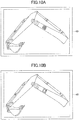
- FIGS. 10A and 10B illustrate examples of display images generated by the stress state detecting unit F9.
- FIG. 10A illustrates a display image showing a state in which a load is hardly applied to the boom 4, namely, a state in which the stress luminescent coating material LP is not emitting light.
- FIG. 10B illustrates a display image showing a state in which a load is applied to the boom 4, namely, a state in which the stress luminescent coating material LP is emitting light.
- the stress state detecting unit F9 implements image processing so that the posture of the excavating attachment in the display images is always the same. Such measure is implemented for the purpose of facilitating viewing by the viewer. Thus, the postures of the excavating attachments in FIG.
- the stress state detecting unit F9 may also be configured to implement image processing to generate a display image that enables three-dimensional viewing so that a viewer can view the image of the excavating attachment from a desired viewpoint (e.g., a viewpoint from below the boom 4), for example.
- the stress state detecting unit F9 may also be configured to display images showing the state in which a load is hardly applied to the boom 4 and the state in which a load is applied to the boom 4 side by side or one on top of the other on the display device 40 or the display device 304, for example.
- the stress state detecting unit F9 can detect the state of stress acting on a component of a construction machine by implementing various image recognition processes on a camera image.
- the stress state detecting unit F9 may detect the state of stress acting on the boom 4 based on the luminance value of the stress luminescent coating material LP on the surface of the boom 4 that is captured in the camera image.
- the luminance value of the stress luminescent coating material LP corresponds to the luminous intensity of light emitted by the stress luminescent coating material LP.
- the stress state detecting unit F9 may determine that a crack has been formed in the boom 4 when the luminance value of the stress luminescent coating material LP is greater than or equal to a predetermined value.
- the stress state detecting unit F9 may predict the time a crack will be formed in the boom 4 based on the temporal transition of the luminance value distribution, for example.
- the stress state detecting unit F9 may save a plurality of display images in chronological order, for example. Each display image may be stored in association with the actual posture of the excavating attachment, weight of soil, and the like, for example.
- the weight of soil may be derived from a boom cylinder pressure or the like, for example.
- the stress state detecting unit F9 may additionally display information indicating that a crack has been formed or the predicted time a crack will be formed on the display image, for example. Also, the stress state detecting unit F9 may emphasize a high stress portion (high luminance portion) in the display image so that the viewer can distinguish the high stress portion (high luminance portion) from other portions. Note that a portion of the display image may be emphasized through brightened display, shaded display, highlight display, or the like, for example.
- the stress state detecting unit F9 may transmit information to the aircraft 200 via the transmitting device S1 so that the camera 205 of the aircraft 200 can capture an image of the attachment from a position at least a predetermined distance away from the attachment.
- the stress state detecting unit F9 may transmit information on the position, posture, orientation, and the like of the excavator 100 to the aircraft 200 so that the camera 205 can capture an image of the boom 4 from a position at least a predetermined distance away from the boom 4.
- the aircraft 200 that receives the information may autonomously fly into the sky to capture images of the respective surfaces of the four metal plates of the boom 4 arranged on the backside (+Z side), the left side (-Y side), the right side (+Y side), and the ventral side (-Z side) of the boom 4, for example.
- the aircraft 200 may be configured to automatically recognize the attachment using image recognition or the like and capture an image of the attachment.
- the attachment may be set up in advance as an image capturing target.
- the shape of the attachment may be registered in advance as the shape of an image recognition target.
- the flight path of the aircraft 200 may be set up in advance.
- the stress state detecting unit F9 may also be configured to output information on the image capturing timing to the exterior via the transmitting device S1 so that a camera can capture a camera image at the appropriate timing. For example, the stress state detecting unit F9 may determine whether a load is applied to the excavating attachment based on outputs from various sensors such as the pilot pressure sensor 15a and a boom cylinder pressure sensor. Upon determining that a load is applied to the excavating attachment, the stress state detecting unit F9 may notify the aircraft 200 to that effect. In this way, the camera 205 can capture an image of the excavating attachment while a load is being applied to the excavating attachment.
- the aircraft 200 can capture an image of the excavating attachment while a load is being applied to the excavating attachment.
- the stress state detecting unit F9 may also notify the aircraft 200 that a load is not being applied to the excavation attachment for the same purpose of enabling the aircraft 200 to capture an image at the appropriate timing, for example.
- the work management system SYS may also include an illuminance sensor for detecting the brightness of ambient light.
- the illuminance sensor is preferably attached to the excavator 100.
- the illuminance sensor may be used to determine the timing for capturing an image of the surface of the boom 4 coated with the stress luminescent coating material LP. This is because light emitted by the stress luminescent coating material LP can be more easily detected as the surrounding becomes darker.
- the excavator 100 may notify the aircraft 200 to that effect.
- the excavator 100 may also notify the aircraft 200 that the brightness of ambient light is not suitable for capturing an image of the surface of the boom 4 for the same purpose, for example.
- the illuminance sensor may be an image sensor such as a camera.
- the stress state detecting unit F9 may be configured to correct the luminance of the camera image and the display image based on the output of the illuminance sensor, for example.
- the work management system SYS enables early detection of a crack forming in the excavating attachment.
- a viewer that views the display image can easily perceive the transition of the stress state of the excavating attachment and can easily devise a maintenance plan for the excavating attachment.
- the viewer that views the display image can easily check the portion of the excavating attachment at which stress is concentrated during operation of the excavator 100, for example.
- subsequent development of the crack can be easily ascertained based on the transition of the stress state of the excavating attachment, for example.
- the remaining service life of the boom 4 is estimated by calculating the stress acting on the center portion of each of the four metal plates arranged on the backside (+Z side), the left side (-Y side), the right side (+Y side) and the ventral side (-Z side) of the boom 4 to thereby calculate the load level acting on the boom 4.
- the stress luminescent coating material LP is coated on a location where a crack is likely to be formed, and in this way, the development of a crack may be directly perceived.
- the stress luminescent coating material LP is applied to the outer surface of the metal plates constituting the boom 4.
- a viewer may also be able to detect a crack formed at the inner side of the metal plate, for example. This is because the stress state of the outer surface of the metal plate is affected by the stress state of the inner surface of the metal plate.
- the aircraft 200 is configured to automatically take off and automatically fly from the parking lot into the sky above a progress region upon detecting that the excavator 100 is in a stopped state during lunch break or after having completed work for the day.
- the present invention is not limited to such configuration.
- the aircraft 200 may be configured to automatically fly from the parking lot into the sky above the progress region at a predetermined time that is set up in advance, or start flying in response to an operation input by an operator.
- the construction machine may also be a bulldozer, a wheel loader, or the like.
Landscapes
- Engineering & Computer Science (AREA)
- Business, Economics & Management (AREA)
- General Physics & Mathematics (AREA)
- Physics & Mathematics (AREA)
- Aviation & Aerospace Engineering (AREA)
- Human Resources & Organizations (AREA)
- Economics (AREA)
- Strategic Management (AREA)
- Mining & Mineral Resources (AREA)
- Structural Engineering (AREA)
- Civil Engineering (AREA)
- General Engineering & Computer Science (AREA)
- Tourism & Hospitality (AREA)
- Marketing (AREA)
- General Business, Economics & Management (AREA)
- Theoretical Computer Science (AREA)
- Remote Sensing (AREA)
- Entrepreneurship & Innovation (AREA)
- Automation & Control Theory (AREA)
- Health & Medical Sciences (AREA)
- Primary Health Care (AREA)
- General Health & Medical Sciences (AREA)
- Radar, Positioning & Navigation (AREA)
- Development Economics (AREA)
- Game Theory and Decision Science (AREA)
- Operations Research (AREA)
- Quality & Reliability (AREA)
- Educational Administration (AREA)
- Mechanical Engineering (AREA)
- Emergency Management (AREA)
- Computer Networks & Wireless Communication (AREA)
- Computer Vision & Pattern Recognition (AREA)
- Signal Processing (AREA)
- Multimedia (AREA)
- Microelectronics & Electronic Packaging (AREA)
- Component Parts Of Construction Machinery (AREA)
- Management, Administration, Business Operations System, And Electronic Commerce (AREA)
- Closed-Circuit Television Systems (AREA)
Abstract
Description
- The present invention relates to a construction machine work management system and a construction machine.
- An excavator that generates topographical information using trajectory information of a cutting edge of a bucket derived based on an output of a stroke sensor is known (see Patent Document 1).
- Patent Document 1: Japanese Unexamined Patent Publication No.
2014-129676 - However, the topographical information generated by the excavator described in
Patent Document 1 does not reflect topographical changes that cannot be determined from the trajectory information of the cutting edge of the bucket, such as soil spilled from the bucket, soil that has crumbled naturally, and the like. - In this respect, a construction machine work management system that is capable of generating topographical information reflecting topographical changes that cannot be determined from trajectory information of a work element is desired.
- A construction machine work management system according to one embodiment of the present invention is configured by a construction machine, an aircraft equipped with a camera, and a management device. The construction machine work management system includes a progress region specifying unit configured to specify a progress region within a work site on which work progress has been made by the construction machine, and a flight path setting unit configured to set up a flight path of the aircraft so that the camera of the aircraft can capture an image of the progress region.
- A construction machine according to one embodiment of the present invention includes an attachment that is coated with a stress luminescent coating material.
- According to an aspect of the present invention, a construction machine work management system that is capable of generating topographical information reflecting topographical changes that cannot be determined from trajectory information of a work element may be provided.
-
-
FIG. 1 is a schematic diagram illustrating an example overall configuration of a work management system; -
FIG. 2 is a diagram illustrating an example system configuration of the work management system; -
FIG. 3 is a functional block diagram of the work management system; -
FIG. 4 is a top view of a work site; -
FIG. 5 is a partial cross-sectional view of the work site; -
FIG. 6 is a top view of an excavator in operation at the work site; -
FIG. 7 is a diagram illustrating another example system configuration of the work management system; -
FIG. 8 is a functional block diagram of yet another example of the work management system; -
FIG. 9 is a perspective view of a boom coated with stress luminescent coating material; -
FIG. 10A is a diagram illustrating an example display image indicating a state of the stress luminescent coating material coated on a boom; and -
FIG. 10B is a diagram illustrating another example display image indicating a state of the stress luminescent coating material coated the boom. - In the following, embodiments of the present invention will be described with reference to the accompanying drawings.
- First, with reference to
FIGS. 1 and2 , a work management system SYS including anexcavator 100 as a construction machine according to an embodiment of the present invention and anaircraft 200 will be described.FIG. 1 is a schematic diagram showing an example configuration of the work management system SYS.FIG. 2 is a system configuration diagram of the work management system SYS. - The work management system SYS is a system for managing work performed by an excavator using an aircraft, and is mainly configured by the
excavator 100, theaircraft 200, and amanagement device 300. The number of theexcavator 100 and the number of theaircraft 200 included in the work management system SYS may be one or plural. In the example ofFIGS. 1 and2 , the work management system SYS includes oneexcavator 100 and oneaircraft 200. - The
aircraft 200 is an autonomous aircraft that is capable of flying by remote control or automatically. Examples of theaircraft 200 include a multicopter (drone), an airship, and the like. In the present embodiment, a quadcopter equipped with a camera is used as theaircraft 200. - The
management device 300 is a device that manages work performed by theexcavator 100, and may be implemented by a computer located outside a work site such as a management center, for example. Themanagement device 300 may also be a portable computer that can be carried by a user, for example. - The
excavator 100 includes alower travelling body 1 and an upper turningbody 3 that is pivotally mounted on thelower travelling body 1 via aturning mechanism 2. Aboom 4 is attached to the upper turningbody 3. Anarm 5 is attached to the tip of theboom 4, and abucket 6 is attached to the tip of thearm 5. Theboom 4, thearm 5, and thebucket 6 corresponding to work elements constitute an excavating attachment, which is an example of an attachment. Theboom 4, thearm 5, and thebucket 6 are hydraulically driven by aboom cylinder 7, anarm cylinder 8, and abucket cylinder 9, respectively. The upper turningbody 3 includes acabin 10 and a power source such as anengine 11. - As shown in
FIG. 2 , theexcavator 100 includes theengine 11, amain pump 14, apilot pump 15, acontrol valve 17, anoperation device 26, acontroller 30, anengine control device 74, and the like. - The
engine 11 is a driving source of theexcavator 100 and may be implemented by a diesel engine that operates to maintain a predetermined rotational speed, for example. An output shaft of theengine 11 is connected to input shafts of themain pump 14 and thepilot pump 15. - The
main pump 14 is a swash-plate variable displacement hydraulic pump that supplies hydraulic oil to thecontrol valve 17 via ahydraulic oil line 16. In themain pump 14, the discharge flow rate per rotation changes in accordance with a change in the swash plate tilt angle. The swash plate tilt angle is controlled by aregulator 14a. Theregulator 14a changes the swash plate tilt angle in accordance with a change in the control current from thecontroller 30. - The
pilot pump 15 is a fixed displacement hydraulic pump that supplies hydraulic oil to various hydraulic control devices, such as theoperation device 26, via apilot line 25. - The
control valve 17 is a set of flow control valves for controlling the flow of hydraulic fluid with respect to hydraulic actuators. Thecontrol valve 17 can selectively supply hydraulic oil received from themain pump 14 through thehydraulic oil line 16 to one or more hydraulic actuators in accordance with a change in pilot pressure based on the operation direction and the operation amount of theoperation device 26. The hydraulic actuators may include theboom cylinder 7, thearm cylinder 8, thebucket cylinder 9, a left travellinghydraulic motor 1A, a right travellinghydraulic motor 1B, and a turninghydraulic motor 2A, for example. - The
operation device 26 is a device used by the operator of theexcavator 100 to operate the hydraulic actuators. Theoperation device 26 receives a supply of hydraulic fluid from thepilot pump 15 via thepilot line 25 and generates the pilot pressure. In turn, the pilot pressure is applied to a pilot port of a corresponding flow control valve through apilot line 25a. The pilot pressure changes in accordance with the operation direction and the operation amount of theoperation device 26. Apilot pressure sensor 15a detects the pilot pressure and outputs the detected value to thecontroller 30. - The
controller 30 is a control device for controlling theexcavator 100. In the present embodiment, thecontroller 30 is implemented by a computer including a CPU, a RAM, a ROM, and the like. The CPU of thecontroller 30 reads programs corresponding to various functions from the ROM, loads the programs into the RAM, and executes the programs to thereby implementing functions corresponding to the programs. - The
engine control device 74 can control theengine 11. For example, theengine control device 74 can control the fuel injection amount so that theengine 11 operates at the engine speed that has been set up via an input device. - A transmitting device S1, a receiving device S2, a positioning device S3, a posture detecting device S4, an orientation detecting device S5, a camera S6, and a
display device 40 that are attached to theupper turning body 3 are connected to thecontroller 30. Thecontroller 30 can execute various computations based on information output by the receiving device S2, the positioning device S3, the posture detecting device S4, the orientation detecting device S5, and the camera S6. Thecontroller 30 can then generate information based on the computation results and transmit the generated information to the exterior via the transmitting device S1 or display the generated information on thedisplay device 40, for example. - The transmitting device S1 can transmit information from the
excavator 100 to the exterior. For example, the transmitting device S1 may transmit information receivable by at least one of theaircraft 200 and themanagement device 300. In the present embodiment, the transmitting device S1 transmits information receivable by themanagement device 300 to themanagement device 300 in response to a request from themanagement device 300. - The receiving device S2 can receive information from the exterior of the
excavator 100. For example, the receiving device S2 may receive information transmitted by at least one of theaircraft 200 and themanagement device 300. In the present embodiment, the receiving device S2 receives information transmitted from themanagement device 300. - The positioning device S3 can acquire position information relating to the position of the
excavator 100. In the present embodiment, the positioning device S3 is a GNSS (GPS) receiver that measures the latitude, longitude, and altitude of theexcavator 100. - The posture detecting device S4 can detect the posture of the
excavator 100. The posture of theexcavator 100 may be the posture of the excavating attachment, for example. In the present embodiment, the posture detecting device S4 includes a boom angle sensor, an arm angle sensor, a bucket angle sensor, and a machine frame tilt sensor. The boom angle sensor is a sensor that acquires the boom angle. The boom angle sensor may include a rotation angle sensor that detects the rotation angle of a boom foot pin, a stroke sensor that detects the stroke amount of theboom cylinder 7, a tilt (acceleration) sensor that detects the tilt angle of theboom 4, and the like. The boom angle sensor may also be a combination of an acceleration sensor and a gyro sensor, for example. Note that the arm angle sensor and the bucket angle sensor may have similar sensor configurations as the boom angle sensor. The machine frame tilt sensor is a sensor that acquires the machine frame tilt angle of theexcavator 100. For example, the machine frame tilt sensor may detect the tilt angle of theupper turning body 3 with respect to the horizontal plane. In the present embodiment, the machine frame tilt sensor is a two-axis acceleration sensor that detects tilt angles around a longitudinal axis and a lateral axis of theupper turning body 3. The longitudinal axis and the lateral axis of theupper turning body 3 may intersect perpendicularly at a center point of theexcavator 100 corresponding to a point on a turning axis of theexcavator 100, for example. The machine frame tilt sensor may also be three-axis acceleration sensor, for example. - The orientation detecting device S5 can detect the orientation of the
excavator 100. The orientation detecting device S5 may include a geomagnetic sensor, a resolver or an encoder relating to the turning axis of theturning mechanism 2, and a gyro sensor, for example. In the present embodiment, the orientation detecting device S5 is implemented by a combination of a three-axis geomagnetic sensor and a gyro sensor. - The
controller 30 can acquire trajectory information of the tip of thebucket 6 based on outputs of the positioning device S3, the posture detecting device S4, and the orientation detecting device S5. - The
controller 30, thedisplay device 40, theengine control device 74, and the like operate by receiving electric power supply from astorage battery 70. Thestorage battery 70 is charged by agenerator 11a that is driven by theengine 11. The electric power of thestorage battery 70 is also supplied to astarter 11b of the engine and the like. Thestarter 11b is driven by the electric power from thestorage battery 70 to start theengine 11. - The camera S6 is attached to the
upper turning body 3 and is capable of capturing images of the periphery of theexcavator 100. In the present embodiment, the camera S6 includes a backside camera for capturing an image of a space behind theexcavator 100, a right side camera for capturing an image of a space on the right side of theexcavator 100, and a left side camera for capturing an image of a space on the left side of theexcavator 100. - The
display device 40 is a device for displaying various types of information and is arranged in the vicinity of the driver's seat in thecabin 10. In the present embodiment, thedisplay device 40 can display an image captured by the camera S6 and an image captured by theaircraft 200. The image captured by the camera S6 includes a composite image obtained by combining captured images of a plurality of cameras. The composite image may be obtained using various image processing techniques such as viewpoint conversion processing and the like, for example. - The
aircraft 200 includes acontrol device 201, a transmittingdevice 202, a receivingdevice 203, anautonomous navigation device 204, acamera 205, aspeaker 206, amicrophone 207, and the like. - The
control device 201 is a device for controlling theaircraft 200. In the present embodiment, thecontrol device 201 is implemented by a computer including a CPU, a RAM, a ROM, and the like. The CPU of thecontrol device 201 can implement various functions corresponding to programs stored in the RAM by reading one or more of the programs from the ROM and loading the programs in the RAM to execute the programs. - The transmitting
device 202 can transmit information from theaircraft 200 to the exterior. For example, the transmittingdevice 202 may transmit information receivable by at least one of theexcavator 100 and themanagement device 300. In the present embodiment, the transmittingdevice 202 repeatedly transmits information receivable by theexcavator 100 and themanagement device 300 at predetermined intervals. The information receivable by theexcavator 100 and themanagement device 300 may include a captured image captured by thecamera 205, for example. - The receiving
device 203 can receive information from the exterior of theaircraft 200. For example, the receivingdevice 203 may receive information transmitted by theexcavator 100 and information transmitted by themanagement device 300. - The
autonomous navigation device 204 is a device for enabling autonomous navigation of theaircraft 200. In the present embodiment, theautonomous navigation device 204 includes a flight control device, an electric motor, and a battery. The flight control device includes various sensors such as a gyro sensor, an acceleration sensor, a geomagnetic sensor (azimuth sensor), an atmospheric pressure sensor, a positioning sensor, an ultrasonic sensor, and the like to implement a posture maintaining function, an altitude maintaining function, and the like. The electric motor receives an electric power supply from the battery to rotate one or more propellers. For example, when theautonomous navigation device 204 receives information relating to a flight path from thecontrol device 201, theautonomous navigation device 204 may separately control the rotation speeds of four propellers and control theaircraft 200 to move along the flight path while maintaining the posture and altitude of theaircraft 200. The information relating to the flight path may include information on the latitude, longitude, and altitude of the flight position, for example. Thecontrol device 201 may acquire the information relating to the flight path from an external source via the receivingdevice 203, for example. Theautonomous navigation device 204 may also change the orientation of theaircraft 200 upon receiving orientation information relating to the orientation from thecontrol device 201, for example. - The
camera 205 is a device for capturing images. In the present embodiment, thecamera 205 is attached to theaircraft 200 so that it can capture an image directly below theaircraft 200. A captured image captured by thecamera 205 may include information on an image capturing position corresponding to the flight position of theaircraft 200, for example, and such information may be used to generate three-dimensional topographical data. Note that thecamera 205 may be a monocular camera or a stereo camera. - The
speaker 206 is a device that outputs audio to the exterior. In the present embodiment, thespeaker 206 may be used to transmit audio information to a person at a work site, for example. - The
microphone 207 is a device that receives audio from the exterior. In the present embodiment, themicrophone 207 may be used to acquire audio generated by a person at a work site, for example. - The
management device 300 includes acontrol device 301, a transmittingdevice 302, a receivingdevice 303, adisplay device 304, anoperation input device 305, and the like. - The
control device 301 is a device for controlling themanagement device 300. In the present embodiment, thecontrol device 301 may be implemented by a computer including a CPU, a RAM, a ROM, and the like. The CPU of thecontrol device 301 can implement various functions corresponding to programs stored in the ROM by reading the programs from the ROM and loading the programs into the RAM to execute the programs. - The transmitting
device 302 can transmit information to the exterior of themanagement device 300. For example, the transmittingdevice 302 may repeatedly transmit information receivable by theaircraft 200 at predetermined intervals. The transmittingdevice 302 may also transmit information receivable by the excavator, for example. In the present embodiment, the transmittingdevice 302 repeatedly transmits information receivable by theaircraft 200 at predetermined intervals. The information receivable by theaircraft 200 may include information relating to the flight path of theaircraft 200, for example. - The receiving
device 303 can receive information from the exterior of themanagement device 300. The receivingdevice 303 may receive information transmitted by at least one of theexcavator 100 and theaircraft 200, for example. In the present embodiment, the receivingdevice 303 receives information transmitted by theaircraft 200. The information transmitted by theaircraft 200 may include a captured image captured by thecamera 205 of theaircraft 200, for example. - The
display device 304 is a device for displaying various types of information. In the present embodiment, thedisplay device 304 is a liquid crystal display that displays information relating to work performed by theexcavator 100, information relating to topographical data, information relating to operation of theaircraft 200, and the like. Thedisplay device 304 may also display a captured image captured by thecamera 205 of theaircraft 200, for example. - The
operation input device 305 is a device for receiving an operation input. In the present embodiment, theoperation input device 305 is implemented by a touch panel arranged on a liquid crystal display. - In the following, various functional elements of the work management system SYS will be described with reference to
FIG. 3. FIG. 3 is a functional block diagram of the work management system SYS. The work management system SYS mainly includes a trajectory information generating unit F1, an approaching object detecting unit F2, an authentication unit F3, a progress region specifying unit F4, a flight path setting unit F5, a topographical data generating unit F6, a work amount calculating unit F7, and a progress rate calculating unit F8. In the present embodiment, thecontroller 30 of theexcavator 100 includes the trajectory information generating unit F1, the approaching object detecting unit F2, and the authentication unit F3, and thecontrol device 301 of themanagement device 300 includes the progress region specifying unit F4, the flight path setting unit F5, the topographical data generating unit F6, the work amount calculating unit F7, and the progress rate calculating unit F8. However, each of the above functional elements may be included in either thecontroller 30 or thecontrol device 301. The above functional elements may also be included in thecontrol device 201 of theaircraft 200, for example. - The trajectory information generating unit F1 can generate trajectory information relating to a trajectory followed by a predetermined portion of the attachment. In the present embodiment, the trajectory information generating unit F1 stores time series data of position information (latitude, longitude, and altitude) of the tip of the
bucket 6 in a nonvolatile storage medium or the like as trajectory information relating to the trajectory followed by the tip of thebucket 6. The position information of the tip of thebucket 6 may be acquired based on outputs of the positioning device S3, the posture detecting device S4, and the orientation detecting device S5, for example. - The approaching object detecting unit F2 can detect an object entering a predetermined region of the work site. An object may be a person, a dump, or the like. In the present embodiment, the approaching object detecting unit F2 detects a person entering a predetermined region of the work site by performing various image recognition processes on a captured image captured by the camera S6 attached to the
excavator 100. The approaching object detecting unit F2 may also detect a person entering the predetermined region using a captured image captured by a camera installed at an entrance/exit gate of the work site or a captured image captured by thecamera 205 of theaircraft 200, for example. In the case of using a captured image captured by a camera installed at the entrance/exit gate of the work site, the camera is connected to at least one of theexcavator 100 and themanagement device 300 via wireless communication or the like. - The authentication unit F3 can authenticate the entering person detected by the approaching object detecting unit F2. In the present embodiment, the entering person may be authenticated when the authentication unit F3 confirms that the entering person is a registered person based on a face image of the entering person included in the captured image of the camera S6 attached to the
excavator 100. The captured image may also be a captured image captured by a camera installed at the entrance/exit gate of the work site or a captured image captured by thecamera 205 of theaircraft 200, for example. The determination as to whether the entering person is a registered person may be implemented by the authentication unit F3 through machine learning by providing the authentication unit F3 with existing images of registered persons, such as photographs included in employee ID cards, for example. - The authentication unit F3 may also authenticate the entering person using authentication methods other than face image authentication. Other authentication methods that may be used include, for example, card authentication or tag authentication using a card reader or an IC tag reader installed at the entrance/exit gate of the work site, pose authentication using image recognition to authenticate an entering person upon detecting that the entering user has taken a predetermined pose, and password authentication using audio recognition to authenticate an entering person upon detecting that the entering person has uttered a predetermined password, for example.
- The progress region specifying unit F4 can specify a progress region within the work site on which the
excavator 100 has made work progress over a predetermined time period. In the present embodiment, the progress region specifying unit F4 specifies a progress region by determining a region passed by the tip of thebucket 6 since a last progress region was specified based on trajectory information generated after the last progress region was specified. The progress region may be specified using a plurality of sets of position information (latitude, longitude, and altitude) to derive its boundaries, for example. - The flight path setting unit F5 can set up a flight path of the
aircraft 200. In the present embodiment, the flight path setting unit F5 sets up the flight path of theaircraft 200 so that thecamera 205 of theaircraft 200 can capture an image of the progress region specified by the progress region specifying unit F4. More specifically, the flight path setting unit F5 sets up the flight path of theaircraft 200 so that the topographical data generating unit F6 can generate three-dimensional topographical data of the progress region based on the captured image captured by thecamera 205. - Also, when a person not authenticated by the authentication unit F3 (hereinafter referred to as "unauthenticated person") enters the predetermined region within the work site, the flight path setting unit F5 may be configured to set up the flight path of the
aircraft 200 so that theaircraft 200 directs itself toward the unauthenticated person, for example. - In this case, the
aircraft 200 may follow the flight path set up by the flight path setting unit F5 to fly from a parking lot into the sky above the unauthenticated person, for example. Then, theaircraft 200 may use thespeaker 206 to output an audio message prompting the unauthenticated person to leave the predetermined region. Alternatively, theaircraft 200 may have thecamera 205 capture an image to be used for face image authentication or pose authentication, for example. Alternatively, theaircraft 200 may use thespeaker 206 to output an audio message prompting the unauthenticated person to utter a password for password authentication, for example. In this case, theaircraft 200 may operate themicrophone 207 to collect the voice of the unauthenticated person uttering the password, for example. Note that when the person is successfully authenticated through face image authentication, pose authentication, password authentication, or the like (hereinafter referred to as "authenticated person"), theaircraft 200 may return to the parking lot without outputting the audio message prompting the person to leave the predetermined region, for example. - The topographical data generating unit F6 can generate three-dimensional topographical data of the work site. In the present embodiment, the topographical data generating unit F6 generates current three-dimensional topographical data of the current work site (work site under construction) based on three-dimensional topographical data of the work site before construction and three-dimensional topographical data of the progress region.
- The three-dimensional topographical data of the work site before construction may be generated based on total station survey measurements, GNSS survey measurements, or the like, for example. The three-dimensional topographical data of the work site before construction may also be generated based on an image of the entire work site captured by the
camera 205 of theaircraft 200, for example. - The topographical data generating unit F6 generates three-dimensional topographical data relating to a progress region based on an image of the progress region captured by the
camera 205 of theaircraft 200. - Then, the topographical data generating unit F6 generates current three-dimensional topographical data of the current work site by joining the three-dimensional topographical data relating to the progress region and three-dimensional topographical data relating to regions other than the progress region. Note that the three-dimensional topographical data of the work site before construction or three-dimensional topographical data previously generated by the topographical data generating unit F6 may be used as is as the three-dimensional topographical data relating to regions other than the progress region. This is because it can be presumed that regions other than the progress region remain unchanged.
- Note that the topographical data generating unit F6 may generate the current three-dimensional topographical data of the current work site using three-dimensional topographical data relating to a plurality of progress regions generated by a plurality of excavators, for example.
- Also, when the topographical data generating unit F6 determines through various image processing that a known object such as an excavator or a dump is present within a part of the progress region, the topographical data generating unit F6 may be configured to refrain from generating three-dimensional topographical data relating to the part of the progress region at that time, for example. In such case, the topographical data generating unit F6 may reacquire an image of the part of the progress region at a different time to generate the three-dimensional topographical data relating to the part of the progress region, for example. This is to prevent the known object from being treated as part of the topography to thereby adversely affect calculation of the work amount, the progress rate, and the like. In the case of displaying the three-dimensional topographical data relating to the part of the progress region before reacquiring an image of the part of the progress region, a message such as "work in progress" may be displayed at the same time, for example. In the case of storing the three-dimensional topographical data relating to the part of the progress region before reacquiring an image of the part of the progress region, information such as a flag indicating that generation of the three-dimensional topographical data relating to the part of the progress region is still in progress may be stored at the same time, for example.
- Also, the topographical data generating unit F6 may be configured to refrain from calculating the work amount, the progress rate, and the like until an image of the part of the progress region is newly acquired, for example. In this case, a message such as "waiting for data acquisition" or the like may be displayed where the work amount, the progress rate, and the like should be displayed. Alternatively, if the work amount, the progress rate, and the like are calculated before reacquiring an image of the part of the progress region, a message indicating that the calculated values being displayed are provisional values may be displayed at the same time, for example.
- The work amount calculating unit F7 can calculate the work amount of the
excavator 100 based on the three-dimensional topographical data of the work site. For example, the work amount calculating unit F7 may calculate the cumulative work amount of theexcavator 100 after starting construction by deriving the volume of soil excavated from the difference between the three-dimensional topographical data of the work site before construction and the current three-dimensional topographical data of the current work site generated by the topographical data generating unit F6. Alternatively, the work amount calculating unit F7 may calculate the work amount of theexcavator 100 over a period from a first time to a second time by deriving the volume of soil excavated during this time period from the difference between three-dimensional topographical data of the work site at the first time generated by the topographical data generating unit F6 and three-dimensional topographical data of the work site at the second time generated by the topographical data generating unit F6, for example. - The progress rate calculating unit F8 can calculate the progress rate of work performed by the
excavator 100 based on the three-dimensional topographical data of the work site. For example, the progress rate calculating unit F8 may calculate a value obtained by dividing the cumulative work amount of theexcavator 100 by a target work amount as the progress rate. The target work amount may be obtained by deriving the volume of soil to be excavated from the difference between the three-dimensional topographical data of the work site before construction and three-dimensional topographical data of the work site when construction is completed (target topographical data), for example. - Also, the progress rate calculating unit F8 may calculate the progress rate of collaborative work performed by a plurality of excavators based on three-dimensional topographical data of the work site. For example, the progress rate calculating unit F8 may calculate a value obtained by dividing the total cumulative work amounts of the plurality of excavators by the target work amount as the progress rate of the collaborative work performed by the plurality of excavators.
- In the following, the topographical data generating function of the work management system SYS will be described with reference to
FIGS. 4 and5 .FIG. 4 is a top view of a work site R0 at the time work for the morning has been completed.FIG. 5 is a partial cross-sectional view of the work site R0 that represents a cross-sectional plane across the one dot chain line shown inFIG. 4 viewed from the direction of the arrows shown inFIG. 4 . InFIG. 4 , region R1 represents a region that already has its topographical changes reflected in three-dimensional topographical data (e.g., region worked on yesterday) from among the regions that have been worked on by theexactor 100. Region R2 represents a region that does not yet have its topographical changes reflected in three-dimensional topographical data (e.g., region worked on this morning) from among the regions that have been worked on by theexactor 100. Region R3 represents a part of the regions that have not yet been worked on by the excavator 100 (e.g., region to be worked on this afternoon). Region R4 represents the parking lot for theaircraft 200. The ranges indicated by the broken lines inFIG. 5 represent image capturing ranges of thecamera 205 of theaircraft 200. - The
control device 301 of themanagement device 300 determines whether theengine 11 of theexcavator 100 has been stopped based on information transmitted by theexcavator 100 and acquired via the receivingdevice 303. When it is determined that theengine 11 has stopped, the progress region specifying unit F4 of thecontrol device 301 specifies region R2 corresponding to the progress region within the work site R0 on which work progress was made by theexcavator 100 this morning. Specifically, the progress region specifying unit F4 acquires trajectory information stored by the trajectory information generating unit F1 of thecontroller 30 during operation of theexcavator 100 and specifies region R2 based on the acquired trajectory information. - Then, the flight path setting unit F5 of the
control device 301 sets up the flight path of theaircraft 200 so that thecamera 205 of theaircraft 200 can capture an image of region R2 as the progress region specified by the progress region specifying unit F4. Then, thecontrol device 301 transmits information relating to the flight path to theaircraft 200 via the transmittingdevice 302. - Upon receiving the information relating to the flight path, the
aircraft 200 flies from the parking lot into the sky above region R2 and captures an image of region R2 with thecamera 205 while flying over the region R2 along the flight path. Theaircraft 200 transmits the captured image to themanagement device 300 via the transmittingdevice 202. - Then, the topographical data generating unit F6 of the
control device 301 generates three-dimensional topographical data relating to region R2 based on the image of region R2 captured by thecamera 205 of theaircraft 200. Then, the topographical data generating unit F6 joins the three-dimensional topographical data relating to region R2 and three-dimensional topographical data relating to regions other than region R2 to generate the current three-dimensional topographical data of the current work site R0. - In the following, the entering person monitoring function of the work management system SYS will be described with reference to
FIG. 4 . When theexcavator 100 is in operation, the work management system SYS may use theaircraft 200 to prompt an unauthenticated person that has entered the work site R0 to leave. - For example, the approaching object detecting unit F2 of the
controller 30 of theexcavator 100 may detect a person entering a predetermined region within the work site R0 by implementing various image recognition processes on a captured image captured by the camera S6 attached to theexcavator 100. In the example ofFIG. 4 , the camera S6 includes a backside camera S6B, a left side camera S6L, and a right side camera S6R. The approaching object detecting unit F2 may also detect a person entering the work site R0 based on a captured image captured by a camera S6E installed at the entrance/exit gate of the work site R0, for example. In this case, thecontroller 30 acquires the captured image captured by the camera S6E via the transmitting device S1. Note that in some embodiments, the approaching object detecting unit F2 may be included in thecontrol device 301 of themanagement device 300, for example. In this case, thecontrol device 301 acquires the captured image captured by the camera S6E and the captured image captured by the camera S6 via the receivingdevice 303. Note that detection of an approaching object may also be implemented using some other sensor such as an infrared sensor, an ultrasonic sensor, or the like. - When a person entering the work site R0 is detected, the authentication unit F3 of the
controller 30 tries to authenticate the entering person detected by the approaching object detecting unit F2. If the entering person cannot be authenticated, the authentication unit F3 notifies themanagement device 300 to that effect. If the entering person could be successfully authenticated, the authentication unit F3 may omit the above notification to themanagement device 300. - Upon receiving the notification that the entering person cannot be authenticated, the
management device 300 directs theaircraft 200 to the entering person. Specifically, the flight path setting unit F5 of thecontrol device 301 sets up the flight path of theaircraft 200 so that theaircraft 200 is directed to the unauthenticated person. - Upon receiving information relating to the flight path set up by the flight path setting unit F5, the
aircraft 200 flies from the parking lot toward the entering person and attempts to authenticate the entering person. For example, theaircraft 200 may use thespeaker 206 to prompt the entering person to utter a password and authenticate the entering person if themicrophone 207 can recognize the password uttered by the entering person. Theaircraft 200 may also authenticate the entering person through pose authentication, for example. - If the entering person cannot be authenticated, the
aircraft 200 uses thespeaker 206 to output an audio message prompting the entering person to leave the work site R0. If the entering person could be authenticated, theaircraft 200 may return to the parking lot without outputting such an audio message. - With the above configuration, the work management system SYS can efficiently and accurately manage work progress made by the
excavator 100 based on a captured image captured by thecamera 205 of theaircraft 200. Also, by generating three-dimensional topographical data using thecamera 205 of theaircraft 200, total station surveying, GNSS surveying, or the like may be omitted, for example. - Also, because the operation management system SYS generates three-dimensional topographical data by having the
aircraft 200 capture an image of only a progress region within the work site R0 on which work progress was made by theexcavator 100 over a predetermined time period, efficient work progress management may be achieved, for example. - Also, the work management system SYS can detect an object such as a person, a dump, or the like that has entered a predetermined region within the work site R0 and can notify an operator of the
excavator 100 or an administrator at a management center to that effect, for example. - In the following, an operator monitoring function of the work management system SYS will be described with reference to
FIG. 6. FIG. 6 is a top view of theexcavator 100 operating at a work site.FIG. 6 illustrates a first work range R5 represented by an annular region in between an outer dashed circle and an inner dashed circle, and a second work range R6 represented by a circular region within the inner dashed circle. The second work range R6 may correspond to the turning range of the excavator 100 (range that can be reached by the excavating attachment), for example. In the example ofFIG. 6 , the authentication unit F3 of thecontroller 30 of theexcavator 100 classifies one or more authenticated persons as either a related person (worker) that is involved in the work being performed or a non-related person that is not involved in the work. - When the approaching object detecting unit F2 detects that an authenticated person classified as a related person has entered the first work range R5, the
controller 30 may notify the operator of theexcavator 100 to that effect via an in-vehicle speaker or thedisplay device 40 installed in thecabin 10, for example. - When the approaching object detecting unit F2 detects that an authenticated person classified as a non-related person has entered the first work range R5, the
controller 30 notifies the operator of theexcavator 100 to the effect and also notifies themanagement device 300 to that effect via the transmitting device S1. - Upon receiving the notification that a non-related person has entered the first work range R5, the
management device 300 directs theaircraft 200 to the non-related person. Specifically, the flight path setting unit F5 of thecontrol device 301 sets up the flight path of theaircraft 200 so that theaircraft 200 is directed to the non-related person. - Upon receiving information relating to the flight path set up by the flight path setting unit F5, the
aircraft 200 flies from the parking lot toward the non-related person and uses thespeaker 206 to output an audio message prompting the non-related person to leave the first work range R5, for example. - When the approaching object detecting unit F2 detects that an authenticated person classified as a related person has entered the second work range R6, the
controller 30 notifies the operator of theexcavator 100 to that effect via the in-vehicle speaker or thedisplay device 40 installed in thecabin 10, for example. In this case, thecontroller 30 may notify the operator of theexcavator 100 to that effect in a mode that is different from that used in the case where the related person has entered the first work range R5 (e.g., a different audio message, larger volume, larger display, or the like). Also, movement of theexcavator 100 may be restricted, for example. - When the approaching object detecting unit F2 detects that an authenticated person classified as a non-related person has entered the second work range R6, the
controller 30 notifies the operator of theexcavator 100 to that effect and also notifies themanagement device 300 to that effect via the transmitting device S1. Thecontroller 30 may also use a speaker installed outside thecabin 10 to output an audio message prompting the non-related person to leave the second work range R6, for example. - Upon receiving the notification that a non-related person has entered the second work range R6, the
management device 300 directs theaircraft 200 to the non-related person. Specifically, the flight path setting unit F5 of thecontrol device 301 sets up the flight path of theaircraft 200 so that theaircraft 200 is directed to the non-related person. - Upon receiving information relating to the flight path set up by the flight path setting unit F5, the
aircraft 200 flies from the parking lot toward the non-related person and uses thespeaker 206 to output an audio message prompting the non-related person to leave the second work range R6. In this case, theaircraft 200 may output the audio message toward the non-related person in a mode different from that used in the case where the non-related person has entered the first work range R5 (e.g., different audio message, larger volume, closer flight, or the like). - With the above configuration, the work management system SYS can achieve the effects as described above with reference to
FIGS. 4 and5 and can also reliably prompt a non-related person to leave a predetermined region within the work site without unduly bothering the operator of theexcavator 100 or a related person (worker), for example. - In the following, another example configuration of the work management system will be described with reference to
FIG. 7. FIG. 7 is a system configuration diagram showing another example configuration of the work management system SYS. The work management system SYS ofFIG. 7 differs from the work management system SYS ofFIG. 2 in that theexcavator 100 includes anaircraft charging unit 71 and a chargingcircuit 72. - The
aircraft charging unit 71 is a mechanism that receives theaircraft 200 and fixes it in place so that theaircraft 200 can be charged. In the example ofFIG. 7 , theaircraft charging unit 71 is installed on the upper face of theupper turning body 3 so that theaircraft 200 can autonomously land on theaircraft charging unit 71. For example, theaircraft 200 may use a captured image captured by thecamera 205 to determine the location of theaircraft charging unit 71 and automatically land on theaircraft charging unit 71. Also, theaircraft charging unit 71 may be configured to lock theaircraft 200 in place so that theaircraft 200 would not be shaken off during operation of theexcavator 100, for example. On the other hand, when theaircraft 200 has to take off, such as when an entering person is detected, the lock can be released. - When the
aircraft 200 has landed on theaircraft charging unit 71 and has been locked in place by theaircraft charging unit 71, thecamera 205 may function as the camera S6, for example. - The charging
circuit 72 is an electric circuit for charging the battery of theaircraft 200 that has landed on theaircraft charging unit 71. Theaircraft 200 that has landed on theaircraft charging unit 71 and is locked in place by theaircraft charging unit 71 can receive electric power from thestorage battery 70 of theexcavator 100 via the chargingcircuit 72. In this way, theaircraft 200 can receive electric power from thestorage battery 70 and operate a flight control device including various sensors such as a gyro sensor, an acceleration sensor, a geomagnetic sensor (azimuth sensor), an atmospheric pressure sensor, a positioning sensor, an ultrasonic sensor, and the like. In this case, theexcavator 100 may use the outputs of the various sensors included in the flight control device, for example. - With the above configuration, the work management system SYS can achieve the effects described above with reference to
FIGS. 4 to 6 and can also achieve an additional effect of being able to operate theaircraft 200 using a power supply of theexcavator 100. - In the following, another example configuration of the work management system SYS will be described with reference to
FIGS. 8 and9 .FIG. 8 is a functional block diagram showing another example configuration of the work management system SYS.FIG. 9 is a perspective view of theboom 4 of theexcavator 100 included in the work management system SYS. Thecontroller 30 of theexcavator 100 shown inFIG. 8 differs from thecontroller 30 shown inFIG. 3 in that it includes a stress state detecting unit F9. Theboom 4 shown inFIG. 9 differs from theboom 4 shown inFIG. 1 in that it is coated with a stress luminescent coating material LP. Note that in other example configurations, thecontrol device 301 may include the stress state detecting unit F9 or thecontrol device 201 of theaircraft 200 may include the stress state detecting unit F9, for example. - The stress state detecting unit F9 can detect a state of stress acting on a component of the construction machine. In the present embodiment, the stress state detecting unit F9 detects the state of stress acting on the
boom 4 based on an image of theboom 4 that is coated with the stress luminescent coating material LP. Note that the component of the construction machine to which stress state detection is implemented may also be some other component such as the frame of the lower travellingbody 1 or thearm 5, for example. - The stress luminescent coating material LP is a coating material that contains a stress luminescent material that emits light when a force is applied thereto. The stress luminescent coating material LP is preferably coated on a component of the construction machine before the construction machine is shipped. However, the stress luminescent coating material LP may also be coated on the component after the construction machine is shipped. The stress luminescent coating material LP emits light in response to an application of force due to expansion/contraction of the component that is coated with the stress luminescent coating material LP. The intensity (luminous intensity) of light emitted by the stress luminescent coating material LP is typically higher when a greater force is applied thereto. Also, when the applied force subsequently decreases the luminous intensity of the emitted light also decreases, and when the applied force disappears, the luminous intensity of the emitted light also disappears. The stress luminescent material included in the stress luminescent coating material LP may be strontium aluminate doped with europium (SrAl2O4:Eu), calcium aluminum aluminosilicate doped with europium (CaAl2SiO8:Eu), or barium calcium titanate doped with praseodymium ((BaCa)TiO3:Pr), for example. In particular, strontium aluminate doped with europium (SrAl2O4:Eu) has the highest light emission intensity among the above stress luminescent materials, and emits green-colored light when a force is applied thereto. Aluminum calcium aluminosilicate doped with europium and barium calcium titanate doped with praseodymium respectively emit blue-colored light and red-colored light when a force is applied thereto. The stress luminescent material may also be a zirconium oxide (ZrO2) dispersion or zinc sulphide doped with manganese (ZnS:Mn), for example. Zinc sulfide doped with manganese emits yellow-orange-colored light when a force is applied thereto.
- The surface of the
boom 4 that is coated with the stress luminescent coating material LP is imaged using a camera including an image capturing element such as a CCD (charge-coupled device), a CMOS (complementary metal-oxide-semiconductor), or the like. Preferably, the surface of theboom 4 is imaged by thecamera 205 of theaircraft 200. The surface of theboom 4 may also be imaged using the camera S6 attached to theupper turning body 3 of theexcavator 100 or a portable camera included in a tablet PC or a smartphone carried by a worker (related person) situated near theexcavator 100, for example. Note that using thecamera 205 of theaircraft 200 may be advantageous in that thecamera 205 may be able to capture portions that are difficult to capture using a portable camera carried by a worker, such as the surface of a metal plate arranged on the backside (+Z side) of theboom 4, for example. Also, using thecamera 205 of theaircraft 200 may be advantageous in that the image can be automatically captured without bothering workers or the like, for example. - In the example shown in
FIG. 9 , the stress luminescent coating material LP is represented by dot hatching. Specifically, the stress luminescent coating material LP is coated on the surfaces of four metal plates arranged on the backside (+Z side), the left side (-Y side), the right side (+Y side) and the ventral side (-Z side) of theboom 4 at a section between aboom cylinder boss 4a and aboom foot 4b of theboom 4. Also, the stress luminescent coating material LP is coated on the surfaces of the four metal plates arranged on the backside (+Z side), the left side (-Y side), the right side (+Y side) and the ventral side (-Z side) of theboom 4 at a section between theboom cylinder boss 4a and aboom top 4c of theboom 4. More specifically, the stress luminescent coating material LP is coated on locations at which stress is likely to be concentrated, such as welding bead portions corresponding to welding portions of partition walls. However, the stress luminescent coating material LP may also be coated on the entire surface of theboom 4, for example. Alternatively, instead of directly applying the stress luminescent coating material LP onto the surface of theboom 4, a sheet coated with the stress luminescent coating material LP may be attached to the surface of theboom 4, for example. The stress luminescent coating material LP may be applied in a similar manner even in the case where the stress luminescent coating material LP is coated on some other component of theexcavator 100 such as thearm 5, for example. - The stress state detecting unit F9 can generate a display image by performing various image processes on images (camera images) captured by a camera at predetermined time intervals. The display image may be an image displayed on the
display device 40, thedisplay device 304, or the like. Note that in some embodiments, the camera image may be used as the display image as is, for example. The camera image may include an image of theentire boom 4, for example. An image of theentire boom 4 may be included in the camera image so that the viewer of the display image can easily perceive the positions of portions of theboom 4 coated with the stress luminescent coating material LP relative to theentire boom 4, for example. Note that the display image may be generated from one camera image or from a plurality of camera images. -
FIGS. 10A and 10B illustrate examples of display images generated by the stress state detecting unit F9. Specifically,FIG. 10A illustrates a display image showing a state in which a load is hardly applied to theboom 4, namely, a state in which the stress luminescent coating material LP is not emitting light.FIG. 10B illustrates a display image showing a state in which a load is applied to theboom 4, namely, a state in which the stress luminescent coating material LP is emitting light. In the present embodiment, the stress state detecting unit F9 implements image processing so that the posture of the excavating attachment in the display images is always the same. Such measure is implemented for the purpose of facilitating viewing by the viewer. Thus, the postures of the excavating attachments inFIG. 10A and FIG. 10B may actually differ from each other but are displayed to be the same in the display images. The stress state detecting unit F9 may also be configured to implement image processing to generate a display image that enables three-dimensional viewing so that a viewer can view the image of the excavating attachment from a desired viewpoint (e.g., a viewpoint from below the boom 4), for example. The stress state detecting unit F9 may also be configured to display images showing the state in which a load is hardly applied to theboom 4 and the state in which a load is applied to theboom 4 side by side or one on top of the other on thedisplay device 40 or thedisplay device 304, for example. - The stress state detecting unit F9 can detect the state of stress acting on a component of a construction machine by implementing various image recognition processes on a camera image. For example, the stress state detecting unit F9 may detect the state of stress acting on the
boom 4 based on the luminance value of the stress luminescent coating material LP on the surface of theboom 4 that is captured in the camera image. The luminance value of the stress luminescent coating material LP corresponds to the luminous intensity of light emitted by the stress luminescent coating material LP. - For example, the stress state detecting unit F9 may determine that a crack has been formed in the
boom 4 when the luminance value of the stress luminescent coating material LP is greater than or equal to a predetermined value. Alternatively, the stress state detecting unit F9 may predict the time a crack will be formed in theboom 4 based on the temporal transition of the luminance value distribution, for example. In this case, the stress state detecting unit F9 may save a plurality of display images in chronological order, for example. Each display image may be stored in association with the actual posture of the excavating attachment, weight of soil, and the like, for example. The weight of soil may be derived from a boom cylinder pressure or the like, for example. - The stress state detecting unit F9 may additionally display information indicating that a crack has been formed or the predicted time a crack will be formed on the display image, for example. Also, the stress state detecting unit F9 may emphasize a high stress portion (high luminance portion) in the display image so that the viewer can distinguish the high stress portion (high luminance portion) from other portions. Note that a portion of the display image may be emphasized through brightened display, shaded display, highlight display, or the like, for example.
- The stress state detecting unit F9 may transmit information to the
aircraft 200 via the transmitting device S1 so that thecamera 205 of theaircraft 200 can capture an image of the attachment from a position at least a predetermined distance away from the attachment. For example, the stress state detecting unit F9 may transmit information on the position, posture, orientation, and the like of theexcavator 100 to theaircraft 200 so that thecamera 205 can capture an image of theboom 4 from a position at least a predetermined distance away from theboom 4. In turn, theaircraft 200 that receives the information may autonomously fly into the sky to capture images of the respective surfaces of the four metal plates of theboom 4 arranged on the backside (+Z side), the left side (-Y side), the right side (+Y side), and the ventral side (-Z side) of theboom 4, for example. Note that in some embodiments, theaircraft 200 may be configured to automatically recognize the attachment using image recognition or the like and capture an image of the attachment. In this case, the attachment may be set up in advance as an image capturing target. For example, the shape of the attachment may be registered in advance as the shape of an image recognition target. Also, in some embodiments, the flight path of theaircraft 200 may be set up in advance. - The stress state detecting unit F9 may also be configured to output information on the image capturing timing to the exterior via the transmitting device S1 so that a camera can capture a camera image at the appropriate timing. For example, the stress state detecting unit F9 may determine whether a load is applied to the excavating attachment based on outputs from various sensors such as the
pilot pressure sensor 15a and a boom cylinder pressure sensor. Upon determining that a load is applied to the excavating attachment, the stress state detecting unit F9 may notify theaircraft 200 to that effect. In this way, thecamera 205 can capture an image of the excavating attachment while a load is being applied to the excavating attachment. By capturing the excavating attachment with thecamera 205 upon receiving such a notification, theaircraft 200 can capture an image of the excavating attachment while a load is being applied to the excavating attachment. The stress state detecting unit F9 may also notify theaircraft 200 that a load is not being applied to the excavation attachment for the same purpose of enabling theaircraft 200 to capture an image at the appropriate timing, for example. - The work management system SYS may also include an illuminance sensor for detecting the brightness of ambient light. The illuminance sensor is preferably attached to the
excavator 100. The illuminance sensor may be used to determine the timing for capturing an image of the surface of theboom 4 coated with the stress luminescent coating material LP. This is because light emitted by the stress luminescent coating material LP can be more easily detected as the surrounding becomes darker. In this case, when theexcavator 100 determines that the brightness of ambient light is suitable for capturing an image of the surface of theboom 4 based on the output of the illuminance sensor, theexcavator 100 may notify theaircraft 200 to that effect. Theexcavator 100 may also notify theaircraft 200 that the brightness of ambient light is not suitable for capturing an image of the surface of theboom 4 for the same purpose, for example. The illuminance sensor may be an image sensor such as a camera. The stress state detecting unit F9 may be configured to correct the luminance of the camera image and the display image based on the output of the illuminance sensor, for example. - With the above configuration, the work management system SYS enables early detection of a crack forming in the excavating attachment. A viewer that views the display image can easily perceive the transition of the stress state of the excavating attachment and can easily devise a maintenance plan for the excavating attachment. Also, the viewer that views the display image can easily check the portion of the excavating attachment at which stress is concentrated during operation of the
excavator 100, for example. Further, when a crack is formed, subsequent development of the crack can be easily ascertained based on the transition of the stress state of the excavating attachment, for example. - Note that in a configuration using a strain gauge, the remaining service life of the
boom 4 is estimated by calculating the stress acting on the center portion of each of the four metal plates arranged on the backside (+Z side), the left side (-Y side), the right side (+Y side) and the ventral side (-Z side) of theboom 4 to thereby calculate the load level acting on theboom 4. On the other hand, in the present embodiment, the stress luminescent coating material LP is coated on a location where a crack is likely to be formed, and in this way, the development of a crack may be directly perceived. - In the above-described embodiment, the stress luminescent coating material LP is applied to the outer surface of the metal plates constituting the
boom 4. However, a viewer may also be able to detect a crack formed at the inner side of the metal plate, for example. This is because the stress state of the outer surface of the metal plate is affected by the stress state of the inner surface of the metal plate. - Although the present invention has been described above with respect to certain illustrative embodiments, the present invention is not limited to the above-described embodiments and various modifications and substitutions can be made to the above-mentioned embodiments without departing from the scope of the present invention.
- For example, in the above-described embodiments, the
aircraft 200 is configured to automatically take off and automatically fly from the parking lot into the sky above a progress region upon detecting that theexcavator 100 is in a stopped state during lunch break or after having completed work for the day. However, the present invention is not limited to such configuration. For example, theaircraft 200 may be configured to automatically fly from the parking lot into the sky above the progress region at a predetermined time that is set up in advance, or start flying in response to an operation input by an operator. - The construction machine may also be a bulldozer, a wheel loader, or the like.
- The present application is based on and claims the benefit of priority of Japanese Patent Application No.
2016-073111 filed on March 31, 2016 2017-006611 filed on January 18, 2017 -
- 1
- lower travelling body
- 1A
- left travelling hydraulic motor
- 1B
- right travelling hydraulic motor
- 2
- turning mechanism
- 2A
- turning hydraulic motor
- 3
- upper turning body
- 4
- boom
- 5
- arm
- 6
- bucket
- 7
- boom cylinder
- 8
- arm cylinder
- 9
- bucket cylinder
- 10
- cabin
- 11
- engine
- 11a
- generator
- 11b
- starter
- 14
- main pump
- 14a
- regulator
- 15
- pilot pump
- 15a
- pilot pressure sensor
- 16
- hydraulic oil line
- 17
- control valve
- 25, 25a
- pilot line
- 26
- operation device
- 30
- controller
- 40
- display device
- 70
- storage battery
- 71
- aircraft charging unit
- 72
- charging circuit
- 74
- engine control device
- 100
- excavator
- 200
- aircraft
- 201
- control device
- 202
- transmitting device
- 203
- receiving device
- 204
- autonomous navigation device
- 205
- camera
- 206
- speaker
- 207
- microphone
- 300
- management device
- 301
- control device
- 302
- transmitting device
- 303
- receiving device
- 304
- display device
- 305
- operation input device
- F1
- trajectory information generating unit
- F2
- approaching object detecting unit
- F3
- authentication unit
- F4
- progress region specifying unit
- F5
- flight path setting unit
- F6
- topographical data generating unit
- F7
- work amount calculating unit
- F8
- progress rate calculating unit
- F9
- stress state detecting unit
- LP
- stress luminescent coating material
- S1
- transmitting device
- S2
- receiving device
- S3
- positioning device
- S4
- posture detecting device
- S5
- orientation detecting device
- S6
- camera
- S6B
- backside camera
- S6L
- left side camera
- S6R
- right side camera
Claims (12)
- A construction machine work management system including a construction machine, an aircraft equipped with a camera, and a management device, the construction machine work management system comprising:a progress region specifying unit configured to specify a progress region within a work site on which work progress has been made by the construction machine; anda flight path setting unit configured to set up a flight path of the aircraft so that the camera of the aircraft can capture an image of the progress region.
- The construction machine work management system according to claim 1, further comprising:a topographical data generating unit configured to generate topographical data relating to the progress region based on the image of the progress region captured by the camera; anda work amount calculating unit configured to calculate a work amount of the construction machine based on the topographical data relating to the progress region.
- The construction machine work management system according to claim 2, wherein
the topographical data generating unit generates topographical data relating to the work site by joining the topographical data relating to the progress region and topographical data relating to a region other than the progress region within the work site. - The construction machine work management system according to claim 3, further comprising:
a progress rate calculating unit configured to calculate a progress rate of work performed by the construction machine based on the topographical data relating to the work site. - The construction machine work management system according to claim 4, wherein
the progress region specifying unit specifies a plurality of progress regions relating to a plurality of construction machines;
the topographical data generating unit generates the topographical data relating to the work site that includes topographical data relating to the plurality of progress regions; and
the progress rate calculating unit calculates a progress rate of collaborative work performed by the plurality of construction machines based on the topographical data relating to the work site. - The construction machine work management system according to claim 1, wherein
when an unauthenticated object enters a predetermined region within the work site, the flight path setting unit sets up the flight path of the aircraft so that the aircraft is directed to the unauthenticated object. - The construction machine work management system according to claim 6, wherein the aircraft includes a speaker and a microphone.
- A construction machine comprising:
an attachment that is coated with a stress luminescent coating material. - The construction machine according to claim 8, further comprising:a stress state detecting unit configured to detect a state of stress acting on the attachment based on an image of the attachment;wherein the image is captured by a camera attached to an aircraft; andwherein the stress state detecting unit transmits information to the aircraft so that the camera can capture the image of the attachment from a position at least a predetermined distance away from the attachment.
- The construction machine according to claim 9, wherein
the stress state detecting unit notifies the aircraft that a load is applied to the attachment so that the camera can capture the image of the attachment when the load is applied to the attachment. - The construction machine according to claim 8, further comprising:a stress state detecting unit configured to detect a state of stress acting on the attachment based on an image of the attachment;wherein the image is captured by a portable camera.
- The construction machine according to claim 8, wherein the stress luminescent coating material is coated on a welding bead portion of the attachment.
Applications Claiming Priority (3)
| Application Number | Priority Date | Filing Date | Title |
|---|---|---|---|
| JP2016073111 | 2016-03-31 | ||
| JP2017006611 | 2017-01-18 | ||
| PCT/JP2017/012829 WO2017170651A1 (en) | 2016-03-31 | 2017-03-29 | Work management system for construction machine, and construction machine |
Publications (2)
| Publication Number | Publication Date |
|---|---|
| EP3438915A1 true EP3438915A1 (en) | 2019-02-06 |
| EP3438915A4 EP3438915A4 (en) | 2019-09-25 |
Family
ID=59964743
Family Applications (1)
| Application Number | Title | Priority Date | Filing Date |
|---|---|---|---|
| EP17775188.0A Withdrawn EP3438915A4 (en) | 2016-03-31 | 2017-03-29 | WORK MANAGEMENT SYSTEM FOR CONSTRUCTION MACHINE, AND CONSTRUCTION MACHINE |
Country Status (6)
| Country | Link |
|---|---|
| US (1) | US11092976B2 (en) |
| EP (1) | EP3438915A4 (en) |
| JP (1) | JP7032308B2 (en) |
| KR (1) | KR20180124064A (en) |
| CN (1) | CN109074612A (en) |
| WO (1) | WO2017170651A1 (en) |
Cited By (2)
| Publication number | Priority date | Publication date | Assignee | Title |
|---|---|---|---|---|
| WO2020229278A1 (en) * | 2019-05-16 | 2020-11-19 | Robert Bosch Gmbh | Method for calculating an excavation volume |
| EP4098813A4 (en) * | 2020-10-01 | 2024-02-28 | Hitachi Construction Machinery Co., Ltd. | CONSTRUCTION MACHINE |
Families Citing this family (34)
| Publication number | Priority date | Publication date | Assignee | Title |
|---|---|---|---|---|
| EP3514288B1 (en) * | 2016-09-16 | 2021-11-10 | Hitachi Construction Machinery Co., Ltd. | Work machinery |
| JP6805883B2 (en) * | 2017-02-28 | 2020-12-23 | コベルコ建機株式会社 | Construction machinery |
| US10569875B2 (en) | 2017-09-29 | 2020-02-25 | Deere & Company | Using unmanned aerial vehicles (UAVs or drones) in forestry imaging and assessment applications |
| JP7040304B2 (en) * | 2018-06-12 | 2022-03-23 | コベルコ建機株式会社 | Construction management system |
| JP2021144260A (en) * | 2018-06-15 | 2021-09-24 | ソニーグループ株式会社 | Information processing device, information processing method, program, and information processing system |
| US11270423B2 (en) | 2018-07-12 | 2022-03-08 | TerraClear Inc. | Object collection system and method |
| JP7176874B2 (en) * | 2018-07-18 | 2022-11-22 | 株式会社フジタ | Mobile flying device for monitoring working machines |
| US10767348B2 (en) * | 2018-07-30 | 2020-09-08 | Deere & Company | Machine stability detection and control |
| JP7580184B2 (en) * | 2019-03-05 | 2024-11-11 | 住友重機械工業株式会社 | Work machines, information management systems, programs |
| JP7334052B2 (en) * | 2019-04-09 | 2023-08-28 | 株式会社小松製作所 | Information processing device, information processing method, trained model generation method, and system |
| CN110221610A (en) * | 2019-06-10 | 2019-09-10 | 吉林大学 | Intelligent operating system and operating method for unmanned construction machinery |
| JP7293933B2 (en) * | 2019-07-17 | 2023-06-20 | コベルコ建機株式会社 | Work machines and work machine support servers |
| JP7293934B2 (en) * | 2019-07-17 | 2023-06-20 | コベルコ建機株式会社 | Work machines and work machine support servers |
| JP7293939B2 (en) * | 2019-07-22 | 2023-06-20 | コベルコ建機株式会社 | Work machines and work machine support servers |
| JP2021021253A (en) * | 2019-07-29 | 2021-02-18 | コベルコ建機株式会社 | Work machine and work machine assistance server |
| JP7043471B2 (en) * | 2019-09-30 | 2022-03-29 | 日立建機株式会社 | Work machine |
| JP7321050B2 (en) * | 2019-10-15 | 2023-08-04 | 水ing株式会社 | System for inspecting water supply facilities |
| JP2021070922A (en) * | 2019-10-29 | 2021-05-06 | 住友重機械工業株式会社 | Shovel |
| WO2021105204A1 (en) * | 2019-11-27 | 2021-06-03 | Novatron Oy | Method for determining situational awareness in worksite |
| JP7328157B2 (en) * | 2020-01-23 | 2023-08-16 | 五洋建設株式会社 | Construction management method and construction method |
| JP7452038B2 (en) * | 2020-01-30 | 2024-03-19 | コベルコ建機株式会社 | Work support system |
| JP7180886B2 (en) * | 2020-02-18 | 2022-11-30 | Necプラットフォームズ株式会社 | Work availability measuring device and work availability measuring method |
| JP7112758B2 (en) * | 2020-03-19 | 2022-08-04 | Totalmasters株式会社 | Construction site safety control device |
| JP7463158B2 (en) * | 2020-03-26 | 2024-04-08 | 住友重機械工業株式会社 | Work Management System |
| JP2021155995A (en) * | 2020-03-26 | 2021-10-07 | 住友重機械工業株式会社 | Shovel support device, shovel management device |
| JP7521359B2 (en) * | 2020-09-29 | 2024-07-24 | コベルコ建機株式会社 | Remote operation support device and remote operation support system |
| JP7472746B2 (en) * | 2020-09-30 | 2024-04-23 | コベルコ建機株式会社 | Work Support Device |
| WO2022137688A1 (en) * | 2020-12-21 | 2022-06-30 | 日本国土開発株式会社 | Construction machine |
| JP7578529B2 (en) * | 2021-03-31 | 2024-11-06 | 株式会社小松製作所 | Construction management system, data processing device, and construction management method |
| GB2610428A (en) * | 2021-09-06 | 2023-03-08 | Bamford Excavators Ltd | A working machine |
| JP7762056B2 (en) * | 2021-12-10 | 2025-10-29 | 株式会社小松製作所 | Display system and display method |
| CN118900944A (en) * | 2022-03-31 | 2024-11-05 | 日立建机株式会社 | Operation support system |
| JP2025006866A (en) * | 2023-06-30 | 2025-01-17 | 株式会社日立製作所 | Autonomous control system and autonomous control method |
| JP2026009665A (en) * | 2024-07-08 | 2026-01-21 | 株式会社日立製作所 | Site information management system and site information management method |
Family Cites Families (31)
| Publication number | Priority date | Publication date | Assignee | Title |
|---|---|---|---|---|
| JPS5234546B1 (en) | 1976-01-27 | 1977-09-03 | ||
| JP2772551B2 (en) * | 1989-07-31 | 1998-07-02 | 大成建設株式会社 | Comprehensive construction management method |
| JP4233932B2 (en) | 2003-06-19 | 2009-03-04 | 日立建機株式会社 | Work support / management system for work machines |
| JP4406695B2 (en) * | 2005-03-31 | 2010-02-03 | 独立行政法人産業技術総合研究所 | Stress measurement system |
| JP5093478B2 (en) * | 2005-08-03 | 2012-12-12 | 独立行政法人産業技術総合研究所 | Object to be measured for stress analysis, coating liquid and stress light emitting structure for forming a coating layer on the object to be measured |
| JP2008186145A (en) * | 2007-01-29 | 2008-08-14 | Mitsubishi Electric Corp | Aerial image processing apparatus and aerial image processing method |
| JP5234546B2 (en) | 2009-02-20 | 2013-07-10 | 独立行政法人産業技術総合研究所 | Stress light emission analysis apparatus, stress light emission analysis method, stress light emission analysis program, and recording medium |
| JP2010203207A (en) * | 2009-03-06 | 2010-09-16 | Caterpillar Japan Ltd | Control device of work machine |
| US20120143482A1 (en) * | 2010-12-02 | 2012-06-07 | Honeywell International Inc. | Electronically file and fly unmanned aerial vehicle |
| US20140012404A1 (en) * | 2012-07-06 | 2014-01-09 | Caterpillar Inc. | Methods and systems for machine cut planning |
| US20140163885A1 (en) * | 2012-12-07 | 2014-06-12 | Caterpillar Inc. | Terrain map updating system |
| US20140316614A1 (en) * | 2012-12-17 | 2014-10-23 | David L. Newman | Drone for collecting images and system for categorizing image data |
| JP6258582B2 (en) | 2012-12-28 | 2018-01-10 | 株式会社小松製作所 | Construction machine display system and control method thereof |
| JP6155032B2 (en) * | 2013-01-31 | 2017-06-28 | セコム株式会社 | Shooting system |
| US9075415B2 (en) * | 2013-03-11 | 2015-07-07 | Airphrame, Inc. | Unmanned aerial vehicle and methods for controlling same |
| FR3004801A1 (en) * | 2013-04-18 | 2014-10-24 | Delta Drone | METHOD FOR MEASURING THE VOLUME OF A MATERIAL AMAS |
| JP6302660B2 (en) * | 2013-12-16 | 2018-03-28 | 株式会社ニコン・トリンブル | Information acquisition system, unmanned air vehicle control device |
| US20170081026A1 (en) * | 2014-09-03 | 2017-03-23 | Infatics, Inc. (DBA DroneDeploy) | System and methods for hosting missions with unmanned aerial vehicles |
| JP5775632B2 (en) | 2014-09-16 | 2015-09-09 | 株式会社トプコン | Aircraft flight control system |
| DE102014218749A1 (en) * | 2014-09-18 | 2016-03-24 | Bayerische Motoren Werke Aktiengesellschaft | Support of an operator of a work machine by means of an unmanned flying object |
| CN104376598A (en) * | 2014-12-09 | 2015-02-25 | 鞍钢集团矿业公司 | Open-pit mine mining and stripping quantity calculating method utilizing plane image aerial-photographing |
| CN104463470B (en) * | 2014-12-10 | 2017-06-20 | 中国水产科学研究院东海水产研究所 | Intertidal Habitats investigation method based on unmanned plane |
| KR101550036B1 (en) * | 2015-02-26 | 2015-09-07 | 주식회사 디안스 | Unmanned security system based on information and communication technology |
| US9494936B2 (en) * | 2015-03-12 | 2016-11-15 | Alarm.Com Incorporated | Robotic assistance in security monitoring |
| CN104765307B (en) * | 2015-03-30 | 2018-06-15 | 陈松 | A kind of unmanned plane system |
| US9685009B2 (en) * | 2015-04-01 | 2017-06-20 | Caterpillar Inc. | System and method for managing mixed fleet worksites using video and audio analytics |
| JP6496182B2 (en) * | 2015-04-28 | 2019-04-03 | 株式会社小松製作所 | Construction planning system |
| US9721158B2 (en) * | 2015-10-19 | 2017-08-01 | Caterpillar Inc. | 3D terrain mapping system and method |
| CN105334862A (en) * | 2015-10-28 | 2016-02-17 | 上海同筑信息科技有限公司 | BIM-based unmanned aerial vehicle monitoring method and system |
| US9786105B2 (en) * | 2015-12-08 | 2017-10-10 | Caterpillar Inc. | Gathering data from machine operating at worksite |
| US20170193646A1 (en) * | 2016-01-05 | 2017-07-06 | Caterpillar Inc. | Dust detection system for a worksite |
-
2017
- 2017-03-29 CN CN201780022022.XA patent/CN109074612A/en active Pending
- 2017-03-29 KR KR1020187028848A patent/KR20180124064A/en not_active Ceased
- 2017-03-29 EP EP17775188.0A patent/EP3438915A4/en not_active Withdrawn
- 2017-03-29 JP JP2018508128A patent/JP7032308B2/en active Active
- 2017-03-29 WO PCT/JP2017/012829 patent/WO2017170651A1/en not_active Ceased
-
2018
- 2018-09-27 US US16/144,021 patent/US11092976B2/en not_active Expired - Fee Related
Cited By (2)
| Publication number | Priority date | Publication date | Assignee | Title |
|---|---|---|---|---|
| WO2020229278A1 (en) * | 2019-05-16 | 2020-11-19 | Robert Bosch Gmbh | Method for calculating an excavation volume |
| EP4098813A4 (en) * | 2020-10-01 | 2024-02-28 | Hitachi Construction Machinery Co., Ltd. | CONSTRUCTION MACHINE |
Also Published As
| Publication number | Publication date |
|---|---|
| JP7032308B2 (en) | 2022-03-08 |
| US11092976B2 (en) | 2021-08-17 |
| US20190028676A1 (en) | 2019-01-24 |
| WO2017170651A1 (en) | 2017-10-05 |
| CN109074612A (en) | 2018-12-21 |
| JPWO2017170651A1 (en) | 2019-03-07 |
| KR20180124064A (en) | 2018-11-20 |
| EP3438915A4 (en) | 2019-09-25 |
Similar Documents
| Publication | Publication Date | Title |
|---|---|---|
| US11092976B2 (en) | Construction machine work management system and construction machine | |
| US20220154431A1 (en) | Shovel and information processing apparatus | |
| CN111417757B (en) | Shovel and management system for shovel | |
| KR102455260B1 (en) | Work support system for shovels and construction machinery | |
| KR102659077B1 (en) | shovel | |
| US11492783B2 (en) | Shovel and autonomous aerial vehicle flying around shovel | |
| US12031302B2 (en) | Excavator | |
| US12460389B2 (en) | Shovel and construction system | |
| CN113661296A (en) | Construction machine and support system | |
| JP7344800B2 (en) | Excavators and shovel management systems | |
| US20200170561A1 (en) | Shovel, assist device for shovel, and management apparatus for shovel | |
| US20240035257A1 (en) | Construction machine and assisting device for construction machine | |
| JP7602741B2 (en) | Systems for Excavators | |
| JP7463158B2 (en) | Work Management System | |
| JP7083597B2 (en) | Construction machinery and its management equipment | |
| US20250003202A1 (en) | Display device for excavator, display device for work machine, and monitor system of excavator | |
| JP2024133110A (en) | Remote operation support device and remote operation support system | |
| US20230014280A1 (en) | Shovel management device, shovel management system, shovel support device, and shovel | |
| US20250215666A1 (en) | Shovel and shovel control system |
Legal Events
| Date | Code | Title | Description |
|---|---|---|---|
| STAA | Information on the status of an ep patent application or granted ep patent |
Free format text: STATUS: THE INTERNATIONAL PUBLICATION HAS BEEN MADE |
|
| PUAI | Public reference made under article 153(3) epc to a published international application that has entered the european phase |
Free format text: ORIGINAL CODE: 0009012 |
|
| STAA | Information on the status of an ep patent application or granted ep patent |
Free format text: STATUS: REQUEST FOR EXAMINATION WAS MADE |
|
| 17P | Request for examination filed |
Effective date: 20181012 |
|
| AK | Designated contracting states |
Kind code of ref document: A1 Designated state(s): AL AT BE BG CH CY CZ DE DK EE ES FI FR GB GR HR HU IE IS IT LI LT LU LV MC MK MT NL NO PL PT RO RS SE SI SK SM TR |
|
| AX | Request for extension of the european patent |
Extension state: BA ME |
|
| RIC1 | Information provided on ipc code assigned before grant |
Ipc: B64C 39/02 20060101ALI20190327BHEP Ipc: E02F 9/20 20060101ALI20190327BHEP Ipc: E02F 9/26 20060101ALI20190327BHEP Ipc: G05D 1/10 20060101ALI20190327BHEP Ipc: B64D 47/08 20060101ALI20190327BHEP Ipc: B64C 13/20 20060101ALI20190327BHEP Ipc: G06Q 50/08 20120101AFI20190327BHEP Ipc: G06Q 10/06 20120101ALI20190327BHEP |
|
| DAV | Request for validation of the european patent (deleted) | ||
| DAX | Request for extension of the european patent (deleted) | ||
| STAA | Information on the status of an ep patent application or granted ep patent |
Free format text: STATUS: EXAMINATION IS IN PROGRESS |
|
| A4 | Supplementary search report drawn up and despatched |
Effective date: 20190826 |
|
| RIC1 | Information provided on ipc code assigned before grant |
Ipc: G05D 1/10 20060101ALI20190820BHEP Ipc: G08B 13/196 20060101ALI20190820BHEP Ipc: E02F 9/20 20060101ALI20190820BHEP Ipc: B64C 39/02 20060101ALI20190820BHEP Ipc: G06Q 50/08 20120101AFI20190820BHEP Ipc: E02F 9/26 20060101ALI20190820BHEP Ipc: G06Q 10/06 20120101ALI20190820BHEP Ipc: B64D 47/08 20060101ALI20190820BHEP Ipc: B64C 13/20 20060101ALI20190820BHEP |
|
| 17Q | First examination report despatched |
Effective date: 20190910 |
|
| STAA | Information on the status of an ep patent application or granted ep patent |
Free format text: STATUS: THE APPLICATION IS DEEMED TO BE WITHDRAWN |
|
| 18D | Application deemed to be withdrawn |
Effective date: 20230830 |