EP3438695A1 - Device for checking the consistency of a positioning - Google Patents
Device for checking the consistency of a positioning Download PDFInfo
- Publication number
- EP3438695A1 EP3438695A1 EP18180664.7A EP18180664A EP3438695A1 EP 3438695 A1 EP3438695 A1 EP 3438695A1 EP 18180664 A EP18180664 A EP 18180664A EP 3438695 A1 EP3438695 A1 EP 3438695A1
- Authority
- EP
- European Patent Office
- Prior art keywords
- signal
- response
- check
- consistency
- distances
- Prior art date
- Legal status (The legal status is an assumption and is not a legal conclusion. Google has not performed a legal analysis and makes no representation as to the accuracy of the status listed.)
- Granted
Links
Images

Classifications
-
- G—PHYSICS
- G01—MEASURING; TESTING
- G01S—RADIO DIRECTION-FINDING; RADIO NAVIGATION; DETERMINING DISTANCE OR VELOCITY BY USE OF RADIO WAVES; LOCATING OR PRESENCE-DETECTING BY USE OF THE REFLECTION OR RERADIATION OF RADIO WAVES; ANALOGOUS ARRANGEMENTS USING OTHER WAVES
- G01S13/00—Systems using the reflection or reradiation of radio waves, e.g. radar systems; Analogous systems using reflection or reradiation of waves whose nature or wavelength is irrelevant or unspecified
- G01S13/88—Radar or analogous systems specially adapted for specific applications
- G01S13/93—Radar or analogous systems specially adapted for specific applications for anti-collision purposes
- G01S13/933—Radar or analogous systems specially adapted for specific applications for anti-collision purposes of aircraft or spacecraft
- G01S13/935—Radar or analogous systems specially adapted for specific applications for anti-collision purposes of aircraft or spacecraft for terrain-avoidance
-
- G—PHYSICS
- G08—SIGNALLING
- G08G—TRAFFIC CONTROL SYSTEMS
- G08G5/00—Traffic control systems for aircraft
- G08G5/50—Navigation or guidance aids
- G08G5/54—Navigation or guidance aids for approach or landing
-
- G—PHYSICS
- G01—MEASURING; TESTING
- G01S—RADIO DIRECTION-FINDING; RADIO NAVIGATION; DETERMINING DISTANCE OR VELOCITY BY USE OF RADIO WAVES; LOCATING OR PRESENCE-DETECTING BY USE OF THE REFLECTION OR RERADIATION OF RADIO WAVES; ANALOGOUS ARRANGEMENTS USING OTHER WAVES
- G01S13/00—Systems using the reflection or reradiation of radio waves, e.g. radar systems; Analogous systems using reflection or reradiation of waves whose nature or wavelength is irrelevant or unspecified
- G01S13/88—Radar or analogous systems specially adapted for specific applications
- G01S13/93—Radar or analogous systems specially adapted for specific applications for anti-collision purposes
- G01S13/933—Radar or analogous systems specially adapted for specific applications for anti-collision purposes of aircraft or spacecraft
-
- G—PHYSICS
- G01—MEASURING; TESTING
- G01S—RADIO DIRECTION-FINDING; RADIO NAVIGATION; DETERMINING DISTANCE OR VELOCITY BY USE OF RADIO WAVES; LOCATING OR PRESENCE-DETECTING BY USE OF THE REFLECTION OR RERADIATION OF RADIO WAVES; ANALOGOUS ARRANGEMENTS USING OTHER WAVES
- G01S13/00—Systems using the reflection or reradiation of radio waves, e.g. radar systems; Analogous systems using reflection or reradiation of waves whose nature or wavelength is irrelevant or unspecified
- G01S13/74—Systems using reradiation of radio waves, e.g. secondary radar systems; Analogous systems
-
- G—PHYSICS
- G01—MEASURING; TESTING
- G01S—RADIO DIRECTION-FINDING; RADIO NAVIGATION; DETERMINING DISTANCE OR VELOCITY BY USE OF RADIO WAVES; LOCATING OR PRESENCE-DETECTING BY USE OF THE REFLECTION OR RERADIATION OF RADIO WAVES; ANALOGOUS ARRANGEMENTS USING OTHER WAVES
- G01S13/00—Systems using the reflection or reradiation of radio waves, e.g. radar systems; Analogous systems using reflection or reradiation of waves whose nature or wavelength is irrelevant or unspecified
- G01S13/88—Radar or analogous systems specially adapted for specific applications
- G01S13/91—Radar or analogous systems specially adapted for specific applications for traffic control
- G01S13/913—Radar or analogous systems specially adapted for specific applications for traffic control for landing purposes
-
- G—PHYSICS
- G01—MEASURING; TESTING
- G01S—RADIO DIRECTION-FINDING; RADIO NAVIGATION; DETERMINING DISTANCE OR VELOCITY BY USE OF RADIO WAVES; LOCATING OR PRESENCE-DETECTING BY USE OF THE REFLECTION OR RERADIATION OF RADIO WAVES; ANALOGOUS ARRANGEMENTS USING OTHER WAVES
- G01S5/00—Position-fixing by co-ordinating two or more direction or position line determinations; Position-fixing by co-ordinating two or more distance determinations
- G01S5/02—Position-fixing by co-ordinating two or more direction or position line determinations; Position-fixing by co-ordinating two or more distance determinations using radio waves
- G01S5/0205—Details
- G01S5/021—Calibration, monitoring or correction
-
- G—PHYSICS
- G01—MEASURING; TESTING
- G01S—RADIO DIRECTION-FINDING; RADIO NAVIGATION; DETERMINING DISTANCE OR VELOCITY BY USE OF RADIO WAVES; LOCATING OR PRESENCE-DETECTING BY USE OF THE REFLECTION OR RERADIATION OF RADIO WAVES; ANALOGOUS ARRANGEMENTS USING OTHER WAVES
- G01S5/00—Position-fixing by co-ordinating two or more direction or position line determinations; Position-fixing by co-ordinating two or more distance determinations
- G01S5/02—Position-fixing by co-ordinating two or more direction or position line determinations; Position-fixing by co-ordinating two or more distance determinations using radio waves
- G01S5/06—Position of source determined by co-ordinating a plurality of position lines defined by path-difference measurements
-
- G—PHYSICS
- G01—MEASURING; TESTING
- G01S—RADIO DIRECTION-FINDING; RADIO NAVIGATION; DETERMINING DISTANCE OR VELOCITY BY USE OF RADIO WAVES; LOCATING OR PRESENCE-DETECTING BY USE OF THE REFLECTION OR RERADIATION OF RADIO WAVES; ANALOGOUS ARRANGEMENTS USING OTHER WAVES
- G01S5/00—Position-fixing by co-ordinating two or more direction or position line determinations; Position-fixing by co-ordinating two or more distance determinations
- G01S5/02—Position-fixing by co-ordinating two or more direction or position line determinations; Position-fixing by co-ordinating two or more distance determinations using radio waves
- G01S5/14—Determining absolute distances from a plurality of spaced points of known location
-
- G—PHYSICS
- G08—SIGNALLING
- G08G—TRAFFIC CONTROL SYSTEMS
- G08G5/00—Traffic control systems for aircraft
- G08G5/50—Navigation or guidance aids
- G08G5/51—Navigation or guidance aids for control when on the ground, e.g. taxiing or rolling
-
- G—PHYSICS
- G08—SIGNALLING
- G08G—TRAFFIC CONTROL SYSTEMS
- G08G5/00—Traffic control systems for aircraft
- G08G5/50—Navigation or guidance aids
- G08G5/52—Navigation or guidance aids for take-off
-
- G—PHYSICS
- G08—SIGNALLING
- G08G—TRAFFIC CONTROL SYSTEMS
- G08G5/00—Traffic control systems for aircraft
- G08G5/50—Navigation or guidance aids
- G08G5/55—Navigation or guidance aids for a single aircraft
-
- G—PHYSICS
- G01—MEASURING; TESTING
- G01S—RADIO DIRECTION-FINDING; RADIO NAVIGATION; DETERMINING DISTANCE OR VELOCITY BY USE OF RADIO WAVES; LOCATING OR PRESENCE-DETECTING BY USE OF THE REFLECTION OR RERADIATION OF RADIO WAVES; ANALOGOUS ARRANGEMENTS USING OTHER WAVES
- G01S13/00—Systems using the reflection or reradiation of radio waves, e.g. radar systems; Analogous systems using reflection or reradiation of waves whose nature or wavelength is irrelevant or unspecified
- G01S13/88—Radar or analogous systems specially adapted for specific applications
- G01S13/93—Radar or analogous systems specially adapted for specific applications for anti-collision purposes
- G01S13/931—Radar or analogous systems specially adapted for specific applications for anti-collision purposes of land vehicles
- G01S2013/9329—Radar or analogous systems specially adapted for specific applications for anti-collision purposes of land vehicles cooperating with reflectors or transponders
Definitions
- the invention relates to a device for checking the consistency of a positioning.
- positions are determined with tools to ensure safe navigation.
- the position may be determined in many ways.
- satellite-based systems e.g. GPS or GLONASS
- ground-based systems for example from WO 2014/011264 A2
- the aircraft in question depends on obtaining a position as accurate as possible from the said systems. Error-prone signals may falsify the positioning and cause navigation errors.
- the invention relates to a device for checking the consistency of a positioning, the device having a transmitting device, a receiving device, a time-measuring unit, a distance determination module and a check module; wherein the transmitting device transmits at least one signal; wherein the receiving device receives at least four response signals from at least four different response elements, wherein a response element receives the at least one signal and transmits a response signal upon receipt of the at least one signal; wherein the time measuring unit determines, for each received response signal, a total delay time from a transmission time of the signal and a reception time of the respective response signal, the distance determination module determining a distance to the respective response element based on each total delay time, and wherein the check module performs a consistency check of a positioning based on distances to the at least four different response elements.
- the invention provides, by means of the transmitting device and the receiving device, four different response signals from ground-based response elements to determine from the time intervals between the transmission of the signal with the transmitting device and the reception of the four response signals, the respective distance to the response elements. This is done by means of the time measuring unit and the distance determining module, wherein the speed of the signals and response signals and the time duration between the reception of the signal from the response element and the transmission of the response signal by the response element is known. For electromagnetic signals and response signals, e.g. radar signals, the speed is the speed of light in air.
- the check module now determines a position based on the at least four distances.
- a check may be made by means of the fourth and thus redundant distance whether the positioning is consistent. It uses redundant distance measurements to check the consistency of all distance measurements. For the first time, this makes it possible to carry out a consistency check for ground-based positioning systems, which detects the presence of incorrect distance values in ground-based positioning systems.
- the check module advantageously performs the consistency check based on distances to at least five different response elements. With at least five different distances, it is possible to identify a faulty response element or a faulty distance and therefore to not consider it. Thus, for a faulty distance value, at least two determined positions that are based on at least three of the five distance values match. Thus, the consistency check may be improved to such an extent that erroneous response signals are identified and not considered when determining the position. Thus, the accuracy of positioning may be improved with a ground-based positioning system.
- the check module performs the consistency check by determining a position based on all distances and checking each distance.
- a single position is first determined, which deviates only slightly from the true position in the presence of a faulty response signal. Then, a check of each individual response signal may be made to check the consistency of the individual distances with respect to the particular position.
- the check module performs the consistency check with a determination of the number N of all distances and the determination of a position by means of an integrity position of a plurality of, preferably of all, positions based on N-1 distances.
- all but one distance is used for a first positioning.
- another distance is omitted.
- the positioning is repeated for all distances.
- Each determined position is subject to a certain inaccuracy, so that no spatial point, but rather a small volume of space is a position output. If all positions match, no response element is defective. If the positions deviate from each other, at least one of the response elements used for the positioning is defective. Since it is not initially identified which of the response elements is defective, an integrity position is determined from the union of the spatial volumes of all determined positions, since at least one of the determined positions must be correct. By combining the unidentifiable correct position value with the unidentifiable wrong position values, at least a high integrity in determining the integrity position is achieved since the integrity position overlaps the correct position.
- the check module has a time filter element, preferably a Kalman filter bank, which performs temporal filtering in the determination of a total delay time.
- This increases the accuracy of the measurements of the time intervals between the transmission of the signal by the transmitting device and the reception of the response signals by the receiving device.
- the transmitting device transmits at least two signals, wherein one of the at least two signals is an altitude radar output signal, and wherein the receiving device receives at least one altitude radar input signal as one of the four response signals.
- the altitude measurement may be additionally used for the consistency check, since the altitude measurement also provides a distance measurement.
- the response element in the altitude radar signal measurement is the ground itself, which returns a reflected signal as a response signal in response to an incoming signal from the transmitting device.
- the invention further relates to a system for checking the consistency of a positioning, wherein the system has at least four response elements, an aircraft, and at least one device according to the preceding description, wherein the at least four response elements emit a response signal after receiving a signal of the device, and wherein the device is connected to the aircraft.
- the position of aircrafts performing their positioning using ground-based systems in which case the ground-based systems are the response elements, may be accurately calculated and the consistency of the measured distances to the response elements may be checked. This increases the safety of the aircraft, as accurate positioning allows for more accurate navigation.
- the at least four response elements are designed as a reflector, beacon, repeater, or transponder.
- the system has a, preferably floating, platform, wherein the at least four response elements are connected to the platform.
- the positions of response elements that are on a floating platform are continually changing due to the waves. Further, a movement of the floating platform may change the position of the response elements.
- an exact position may also be determined with response elements which are subject to positional fluctuations.
- the consistency check may further determine the exact position of the aircraft so that the relative position of the aircraft to the floating platform is e.g. may be determined very accurately during a landing maneuver.
- the invention relates to a method for checking the consistency of a positioning with the steps: a) transmitting a signal with a transmitting device; b) receiving at least four response signals from at least four different response elements by means of a receiving device, wherein a response element receives the signal and emits a response signal upon receipt of the signal; c) determining a total delay time for each received response signal from a time of transmission of the signal and a time of receipt of the respective response signal with a time measurement unit; d) determining a distance based on each total delay time to the respective response element with a distance determination module, and e) checking a consistency of the distances with a consistency check by means of the determination of a position based on distances to the at least four different response elements with a check module.
- the method is used in a landing maneuver, or a takeoff maneuver, or taxiing of an aircraft.
- the system for checking the consistency of a positioning is referred to in its entirety by the reference numeral 1, hereinafter, as shown in FIG. 1 .
- the system 1 comprises an aircraft 3 in which a device 2 for checking the consistency of a positioning is arranged and connected to the aircraft 3. Further, the system 1 comprises response elements 5 mounted on a platform 4.
- FIG. 1 shows a landing maneuver of the aircraft 3.
- a signal 6 is emitted by the device 2.
- the signal 6 is received by the response elements 5.
- the response elements 5 then send out response signals 7. These response signals 7 may be received by the device 2.
- the device 2 is described in more detail in FIG. 2 .
- the device 2 comprises a transmitting device 20, a receiving device 21, a time measuring unit 22, a distance determination module 23, a check module 24, and a filter unit 25.
- the transmitting device 20 transmits at least one signal 6.
- the transmitting device 20 may consist of several elements that are able to send signals. In this case, the transmitting device 20 may also emit a signal 6', which may be an altitude radar output signal.
- the signals 6 are received by response elements 5.
- the response elements 5 are configured to emit a response signal 7 when they receive a signal 6.
- the response element 7 may be a reflector and the response signal 7 may be a reflected signal.
- the response signal 7 may be a separate signal from a response element 5 e.g. a beacon, a transponder, or a repeater, the signal being emitted by the response element 5 in response to the receipt of the signal 6.
- the altitude radar output signal is reflected from the earth's surface.
- the earth's surface is the response element 5 and the signal reflected by the earth's surface is the response signal 7'or the altitude radar input signal.
- the receiving device 21 receives the response signals 7, 7'. In this case, the receiving device 21 receives at least four response signals 7, 7'. The receiving device 21 thus receives a redundant number of response signals 5 for a three-dimensional positioning.
- the receiving device 21 may also consist of a plurality of components, each of which may receive signals for itself. Thus, a portion of the receiving device 21 may be configured to receive only altitude radar input signals.
- the time measuring unit 22 determines the duration between the transmission of the signal 6 or 6'and the reception of a response signal 7 or 7'.
- the time measuring unit 22 may also determine the duration between the transmission of the altitude radar output signal and the reception of the altitude radar input signal.
- the distance determination module 23 determines the distance between the respective response element 5 and the device 2 using the measured durations.
- the distance determination module 23 uses the speed of light to calculate the distance from the measured time traveled by the signal 6, 6'and the response signal 7, 7'. Further, the distance determination module 23 considers the duration that elapses between the reception of the signal 6, 6'and the transmission of the response signal 7, 7'. Thus, the distance determination module 23 may determine the distance of the device 2 to a response element 5.
- the distance determination module 23 determines from the at least four response signals 7, 7' at least four different distances to different response elements. 5
- the check module 24 determines the position of the aircraft 3. With the at least four different distances, the check module 24 may check the consistency of the four distances so far that it may be determined whether one of the four response elements 5 belonging to the distances was faulty, i.e. whether e.g. a response element 5 has sent a response signal 7 after receiving the signal 6 with a long delay. In a delayed transmission of a response signal 7 by a response element 5, the duration between the transmission of the signal 6 and the reception of the response signal 7 of the respective response element 5 would be too long. Therefore, the distance determination module would determine a distance to the respective response element 5 being too large. With at least four response signals 7, 7', the check module 24 may recognize this fact.
- a filter unit 25 which may be a Kalman filter bank, performs time filtering on the check module 24 to improve the accuracy of the time measurement.
- the check module 24 determines the position based on all distances to the response elements 5. To check the consistency, a check of each individual distance to a response element 5 is performed, then.
- the check module 24 first determines the number N of available distances to the response elements 5. Then, the check module 24 determines a position from N-1 distances, ignoring the Nth distance. The check module 24 repeats this, wherein each distance is disregarded in one of the repetitions. If all distances have been determined correctly, all determined positions will be identical. If one of the distances should not be correct, at least one of the determined positions is correct. However, it is not known which position is correct. Therefore, an integrity position is determined from all N determined positions, wherein the integrity position represents an overlap area of the positions consisting of spatial volumes. This integrity position also includes portions of the volume of the correct position and may therefore be used for positioning.
- FIG. 3 shows a method 100 for checking the consistency of a positioning based on a schematic flow chart.
- a signal is transmitted 101 with a transmitting device.
- the transmitting device 20 in this case emits at least one signal 6.
- the transmitting device 20 may consist of several elements that are able to send signals. In this case, the transmitting device 20 may also emit a signal 6', which may be an altitude radar output signal.
- the response elements 5 receive the signals 6.
- the response elements 5 are configured to emit a response signal 7 when they receive a signal 6.
- the response element 5 may be a reflector and the response signal 7 may also be a reflected signal.
- the response signal 7 may be a separate signal from a beacon, a transponder or a repeater as a response element 5, which is emitted by the response element 5 in response to the receipt of the signal 6.
- the altitude radar output signal is reflected from the earth's surface.
- the earth's surface is the response element 5 and the signal reflected by the earth's surface is the response signal 7'or the altitude radar input signal.
- a second step b) at least four response signals from at least four different response elements are received by means of a receiving device 102.
- the receiving device 21 receives the response signals 7, 7'. In this case, the receiving device 21 receives at least four response signals 7, 7'.
- the receiving device 21 thus receives a redundant number of response signals 5 for a three-dimensional positioning.
- the receiving device 21 may also consist of a plurality of components, each of which may receive signals for itself. Thus, a portion of the receiving device 21 may be configured to receive only altitude radar input signals.
- a third step c) the total delay is determined for each received response signal from a transmission time of the signal 6, 6' and a reception time of the respective response signal 7, 7' a time measuring unit.
- the time measuring unit 22 determines the duration between the transmission of the signal 6 or 6' and the reception of a response signal 7 or 7'.
- the time measuring unit 22 may also determine the duration between the transmission of the altitude radar output signals and the reception of the altitude radar input signals.
- a distance is determined 104 based on the total delay times of the signals and response signals to the respective response element by means of a distance determination module 104.
- the distance determination module 23 determines the distance between the respective response element 5 and the device 2 using the measured durations.
- the distance determination module 23 uses the speed of light to calculate the distance from the measured period traveled by the signal 6, 6' and the response signal 7, 7'. Further, the distance determination module 23 considers the duration that elapses between the reception of the signal 6, 6' and the transmission of the response signal 7, 7'. Thus, the distance determination module 23 may determine the distance of the device 2 to a response element 5.
- the distance determination module 23 determines at least four different distances to different response elements 5 from the at least four response signals 7, 7'.
- a fifth step e) the consistency of the distances is checked with a consistency check by means of a positioning based on the distances to at least four different response elements by means of a check module 105.
- the check module 24 determines the position of the aircraft 3.
- the check module 24 may check the consistency of the four distances so far that it may be determined whether one of the four response elements 5 belonging to the distances was faulty, i.e. whether e.g. a response element 5 has sent a response signal 7 after receiving the signal 6 with a long delay.
- the distance determination module would determine a distance to the respective response element 5 being too large.
- the check module 24 may recognize this fact.
- four response signals 7, 7' are insufficient to identify the faulty response element 5.
- the check module 24 requires at least five different distances, so that the receiving device 21 must receive at least five response signals 7, 7' from five different response elements 5.
- a filter unit 25 which may be a Kalman filter bank, performs time filtering on the check module 24 to improve the accuracy of the time measurement.
- the check module 24 determines the position based on all distances to the response elements 5. To check the consistency then a check of each individual distance to a response element 5 is performed.
- the check module 24 first determines the number N of available distances to the response elements 5. Then, the check module 24 determines a position from N-1 distances, ignoring the Nth distance. The check module 24 repeats this, wherein each distance is disregarded in one of the repetitions. If all distances have been determined correctly, all determined positions will be identical. If one of the distances should not be correct, at least one of the determined positions is correct. However, it is not known which position is correct. Therefore, an integrity position is determined from all N determined positions, wherein the integrity position represents an overlap area of the positions consisting of spatial volumes. This integrity position also includes portions of the volume of the correct position and may therefore be used for positioning.
- the method 100 described above is preferably used in a landing maneuver or a takeoff maneuver or in the taxiing of an aircraft. This makes it possible to ensure that the aircraft may determine its own position relative to the response elements even if the landmarks are not visible or missing.
Landscapes
- Engineering & Computer Science (AREA)
- Radar, Positioning & Navigation (AREA)
- Remote Sensing (AREA)
- Physics & Mathematics (AREA)
- General Physics & Mathematics (AREA)
- Aviation & Aerospace Engineering (AREA)
- Computer Networks & Wireless Communication (AREA)
- Electromagnetism (AREA)
- Radar Systems Or Details Thereof (AREA)
Abstract
Description
- The invention relates to a device for checking the consistency of a positioning.
- In aviation, positions are determined with tools to ensure safe navigation. The position may be determined in many ways. Thus, among others, satellite-based systems (e.g. GPS or GLONASS) or ground-based systems (for example from
WO 2014/011264 A2 ) are known. If no landmarks on the earth may be detected or detected from the airspace, the aircraft in question depends on obtaining a position as accurate as possible from the said systems. Error-prone signals may falsify the positioning and cause navigation errors. - It is known from
EP 2 402 785 B1 for satellite-based systems to use, for example, so-called RAIM (Receiver Autonomous Integrity Monitoring) algorithms, which may detect erroneous signals from satellite-based systems and identify their transmitters. The time signals transmitted by the satellites to a receiver on the ground or in the air above the earth are evaluated by statistical methods against each other to check their consistency in this way. - For ground-based systems that rely on the aerial vehicle emitting a signal that is answered by ground-based receivers, and based on which distances to the receivers are calculated, nowadays faulty signals are neither detected nor their transmitters identified.
- Therefore, it is the object of the invention to provide an apparatus and a method with which erroneous distance values may be detected in ground-based positioning systems.
- The object is solved by the features of the independent claims. Advantageous developments are the subject of the dependent claims and the following description.
- The invention relates to a device for checking the consistency of a positioning, the device having a transmitting device, a receiving device, a time-measuring unit, a distance determination module and a check module; wherein the transmitting device transmits at least one signal; wherein the receiving device receives at least four response signals from at least four different response elements, wherein a response element receives the at least one signal and transmits a response signal upon receipt of the at least one signal; wherein the time measuring unit determines, for each received response signal, a total delay time from a transmission time of the signal and a reception time of the respective response signal, the distance determination module determining a distance to the respective response element based on each total delay time, and wherein the check module performs a consistency check of a positioning based on distances to the at least four different response elements.
- The invention provides, by means of the transmitting device and the receiving device, four different response signals from ground-based response elements to determine from the time intervals between the transmission of the signal with the transmitting device and the reception of the four response signals, the respective distance to the response elements. This is done by means of the time measuring unit and the distance determining module, wherein the speed of the signals and response signals and the time duration between the reception of the signal from the response element and the transmission of the response signal by the response element is known. For electromagnetic signals and response signals, e.g. radar signals, the speed is the speed of light in air. The check module now determines a position based on the at least four distances. Since only three distances to three different points are required for a positioning in three-dimensional space, a check may be made by means of the fourth and thus redundant distance whether the positioning is consistent. It uses redundant distance measurements to check the consistency of all distance measurements. For the first time, this makes it possible to carry out a consistency check for ground-based positioning systems, which detects the presence of incorrect distance values in ground-based positioning systems. The check module advantageously performs the consistency check based on distances to at least five different response elements. With at least five different distances, it is possible to identify a faulty response element or a faulty distance and therefore to not consider it. Thus, for a faulty distance value, at least two determined positions that are based on at least three of the five distance values match. Thus, the consistency check may be improved to such an extent that erroneous response signals are identified and not considered when determining the position. Thus, the accuracy of positioning may be improved with a ground-based positioning system.
- Advantageously, the check module performs the consistency check by determining a position based on all distances and checking each distance.
- By using all the distances in the determination of the position, a single position is first determined, which deviates only slightly from the true position in the presence of a faulty response signal. Then, a check of each individual response signal may be made to check the consistency of the individual distances with respect to the particular position.
- Further, it is advantageous if the check module performs the consistency check with a determination of the number N of all distances and the determination of a position by means of an integrity position of a plurality of, preferably of all, positions based on N-1 distances.
- In this case, all but one distance is used for a first positioning. In the second determination of a position, another distance is omitted. The positioning is repeated for all distances. Each determined position is subject to a certain inaccuracy, so that no spatial point, but rather a small volume of space is a position output. If all positions match, no response element is defective. If the positions deviate from each other, at least one of the response elements used for the positioning is defective. Since it is not initially identified which of the response elements is defective, an integrity position is determined from the union of the spatial volumes of all determined positions, since at least one of the determined positions must be correct. By combining the unidentifiable correct position value with the unidentifiable wrong position values, at least a high integrity in determining the integrity position is achieved since the integrity position overlaps the correct position.
- It is expedient if the check module has a time filter element, preferably a Kalman filter bank, which performs temporal filtering in the determination of a total delay time.
- This increases the accuracy of the measurements of the time intervals between the transmission of the signal by the transmitting device and the reception of the response signals by the receiving device.
- Advantageously, the transmitting device transmits at least two signals, wherein one of the at least two signals is an altitude radar output signal, and wherein the receiving device receives at least one altitude radar input signal as one of the four response signals.
- With the use of the altitude radar output signal and the altitude radar input signal, the altitude measurement may be additionally used for the consistency check, since the altitude measurement also provides a distance measurement. The response element in the altitude radar signal measurement is the ground itself, which returns a reflected signal as a response signal in response to an incoming signal from the transmitting device.
- The invention further relates to a system for checking the consistency of a positioning, wherein the system has at least four response elements, an aircraft, and at least one device according to the preceding description, wherein the at least four response elements emit a response signal after receiving a signal of the device, and wherein the device is connected to the aircraft.
- With the system, the position of aircrafts performing their positioning using ground-based systems, in which case the ground-based systems are the response elements, may be accurately calculated and the consistency of the measured distances to the response elements may be checked. This increases the safety of the aircraft, as accurate positioning allows for more accurate navigation.
- Advantageously, the at least four response elements are designed as a reflector, beacon, repeater, or transponder.
- Advantageously, the system has a, preferably floating, platform, wherein the at least four response elements are connected to the platform.
- The positions of response elements that are on a floating platform are continually changing due to the waves. Further, a movement of the floating platform may change the position of the response elements. By means of the invention, an exact position may also be determined with response elements which are subject to positional fluctuations. The consistency check may further determine the exact position of the aircraft so that the relative position of the aircraft to the floating platform is e.g. may be determined very accurately during a landing maneuver.
- Furthermore, the invention relates to a method for checking the consistency of a positioning with the steps: a) transmitting a signal with a transmitting device; b) receiving at least four response signals from at least four different response elements by means of a receiving device, wherein a response element receives the signal and emits a response signal upon receipt of the signal; c) determining a total delay time for each received response signal from a time of transmission of the signal and a time of receipt of the respective response signal with a time measurement unit; d) determining a distance based on each total delay time to the respective response element with a distance determination module, and e) checking a consistency of the distances with a consistency check by means of the determination of a position based on distances to the at least four different response elements with a check module.
- Advantageously, the method is used in a landing maneuver, or a takeoff maneuver, or taxiing of an aircraft.
- Precisely in landing or takeoff maneuvers of an aircraft, an accurate positioning is advantageous to avoid collisions with objects located close to the ground or objects protruding from the ground.
- In the following the invention will be described by means of an exemplary embodiment using the attached drawing.
-
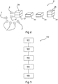
FIG.1 shows a schematic drawing of a system for checking the consistency of a positioning; -
FIG.2 shows a schematic drawing of a device for checking the consistency of a positioning; and -
FIG. 3 shows a schematic flow diagram of a method for checking the consistency of a positioning. - The system for checking the consistency of a positioning is referred to in its entirety by the reference numeral 1, hereinafter, as shown in
FIG. 1 . - The system 1 comprises an
aircraft 3 in which adevice 2 for checking the consistency of a positioning is arranged and connected to theaircraft 3. Further, the system 1 comprisesresponse elements 5 mounted on a platform 4. -
FIG. 1 shows a landing maneuver of theaircraft 3. Asignal 6 is emitted by thedevice 2. Thesignal 6 is received by theresponse elements 5. Theresponse elements 5 then send outresponse signals 7. These response signals 7 may be received by thedevice 2. - The
device 2 is described in more detail inFIG. 2 . Thedevice 2 comprises a transmittingdevice 20, a receivingdevice 21, atime measuring unit 22, adistance determination module 23, acheck module 24, and afilter unit 25. - The transmitting
device 20 transmits at least onesignal 6. The transmittingdevice 20 may consist of several elements that are able to send signals. In this case, the transmittingdevice 20 may also emit a signal 6', which may be an altitude radar output signal. - The
signals 6 are received byresponse elements 5. Theresponse elements 5 are configured to emit aresponse signal 7 when they receive asignal 6. In this case, theresponse element 7 may be a reflector and theresponse signal 7 may be a reflected signal. Alternatively or additionally, theresponse signal 7 may be a separate signal from aresponse element 5 e.g. a beacon, a transponder, or a repeater, the signal being emitted by theresponse element 5 in response to the receipt of thesignal 6. - In the case of signal 6', which may be an altitude radar output signal, the altitude radar output signal is reflected from the earth's surface. In this case, the earth's surface is the
response element 5 and the signal reflected by the earth's surface is the response signal 7'or the altitude radar input signal. - The receiving
device 21 receives the response signals 7, 7'. In this case, the receivingdevice 21 receives at least fourresponse signals 7, 7'. The receivingdevice 21 thus receives a redundant number ofresponse signals 5 for a three-dimensional positioning. The receivingdevice 21 may also consist of a plurality of components, each of which may receive signals for itself. Thus, a portion of the receivingdevice 21 may be configured to receive only altitude radar input signals. - The
time measuring unit 22 determines the duration between the transmission of thesignal 6 or 6'and the reception of aresponse signal 7 or 7'. - In this case, the
time measuring unit 22 may also determine the duration between the transmission of the altitude radar output signal and the reception of the altitude radar input signal. - The
distance determination module 23 determines the distance between therespective response element 5 and thedevice 2 using the measured durations. Here, thedistance determination module 23 uses the speed of light to calculate the distance from the measured time traveled by thesignal 6, 6'and theresponse signal 7, 7'. Further, thedistance determination module 23 considers the duration that elapses between the reception of thesignal 6, 6'and the transmission of theresponse signal 7, 7'. Thus, thedistance determination module 23 may determine the distance of thedevice 2 to aresponse element 5. - The
distance determination module 23 determines from the at least fourresponse signals 7, 7' at least four different distances to different response elements. 5 - With at least four different distances, the
check module 24 determines the position of theaircraft 3. With the at least four different distances, thecheck module 24 may check the consistency of the four distances so far that it may be determined whether one of the fourresponse elements 5 belonging to the distances was faulty, i.e. whether e.g. aresponse element 5 has sent aresponse signal 7 after receiving thesignal 6 with a long delay. In a delayed transmission of aresponse signal 7 by aresponse element 5, the duration between the transmission of thesignal 6 and the reception of theresponse signal 7 of therespective response element 5 would be too long. Therefore, the distance determination module would determine a distance to therespective response element 5 being too large. With at least fourresponse signals 7, 7', thecheck module 24 may recognize this fact. However, fourresponse signals 7, 7' are insufficient to identify thefaulty response element 5. For this purpose, thecheck module 24 requires at least five different distances, so that the receivingdevice 21 must receive at least fiveresponse signals 7, 7' from fivedifferent response elements 5. In this case, afilter unit 25, which may be a Kalman filter bank, performs time filtering on thecheck module 24 to improve the accuracy of the time measurement. - In a first embodiment, the
check module 24 determines the position based on all distances to theresponse elements 5. To check the consistency, a check of each individual distance to aresponse element 5 is performed, then. - In a second alternative or additional embodiment, the
check module 24 first determines the number N of available distances to theresponse elements 5. Then, thecheck module 24 determines a position from N-1 distances, ignoring the Nth distance. Thecheck module 24 repeats this, wherein each distance is disregarded in one of the repetitions. If all distances have been determined correctly, all determined positions will be identical. If one of the distances should not be correct, at least one of the determined positions is correct. However, it is not known which position is correct. Therefore, an integrity position is determined from all N determined positions, wherein the integrity position represents an overlap area of the positions consisting of spatial volumes. This integrity position also includes portions of the volume of the correct position and may therefore be used for positioning. -
FIG. 3 shows amethod 100 for checking the consistency of a positioning based on a schematic flow chart. - In a first step a), a signal is transmitted 101 with a transmitting device. The transmitting
device 20 in this case emits at least onesignal 6. The transmittingdevice 20 may consist of several elements that are able to send signals. In this case, the transmittingdevice 20 may also emit a signal 6', which may be an altitude radar output signal. - The
response elements 5 receive thesignals 6. Theresponse elements 5 are configured to emit aresponse signal 7 when they receive asignal 6. In this case, theresponse element 5 may be a reflector and theresponse signal 7 may also be a reflected signal. Alternatively or additionally, theresponse signal 7 may be a separate signal from a beacon, a transponder or a repeater as aresponse element 5, which is emitted by theresponse element 5 in response to the receipt of thesignal 6. - In the case of signal 6', which may be an altitude radar output signal, the altitude radar output signal is reflected from the earth's surface. In this case, the earth's surface is the
response element 5 and the signal reflected by the earth's surface is the response signal 7'or the altitude radar input signal. - In a second step b), at least four response signals from at least four different response elements are received by means of a receiving
device 102. The receivingdevice 21 receives the response signals 7, 7'. In this case, the receivingdevice 21 receives at least fourresponse signals 7, 7'. The receivingdevice 21 thus receives a redundant number ofresponse signals 5 for a three-dimensional positioning. The receivingdevice 21 may also consist of a plurality of components, each of which may receive signals for itself. Thus, a portion of the receivingdevice 21 may be configured to receive only altitude radar input signals. - In a third step c), the total delay is determined for each received response signal from a transmission time of the
signal 6, 6' and a reception time of therespective response signal 7, 7' a time measuring unit. Thetime measuring unit 22 determines the duration between the transmission of thesignal 6 or 6' and the reception of aresponse signal 7 or 7'. - In this case, the
time measuring unit 22 may also determine the duration between the transmission of the altitude radar output signals and the reception of the altitude radar input signals. - In a fourth step d), a distance is determined 104 based on the total delay times of the signals and response signals to the respective response element by means of a
distance determination module 104. Thedistance determination module 23 determines the distance between therespective response element 5 and thedevice 2 using the measured durations. Thedistance determination module 23 uses the speed of light to calculate the distance from the measured period traveled by thesignal 6, 6' and theresponse signal 7, 7'. Further, thedistance determination module 23 considers the duration that elapses between the reception of thesignal 6, 6' and the transmission of theresponse signal 7, 7'. Thus, thedistance determination module 23 may determine the distance of thedevice 2 to aresponse element 5. - The
distance determination module 23 determines at least four different distances todifferent response elements 5 from the at least fourresponse signals 7, 7'. - In a fifth step e), the consistency of the distances is checked with a consistency check by means of a positioning based on the distances to at least four different response elements by means of a
check module 105. With the at least four different distances, thecheck module 24 determines the position of theaircraft 3. With the at least four different distances, thecheck module 24 may check the consistency of the four distances so far that it may be determined whether one of the fourresponse elements 5 belonging to the distances was faulty, i.e. whether e.g. aresponse element 5 has sent aresponse signal 7 after receiving thesignal 6 with a long delay. In a delayed transmission of aresponse signal 7 by aresponse element 5, the duration between the transmission of thesignal 6 and the reception of theresponse signal 7 of therespective response element 5 would be too long. Therefore, the distance determination module would determine a distance to therespective response element 5 being too large. With at least fourresponse signals 7, 7', thecheck module 24 may recognize this fact. However, fourresponse signals 7, 7' are insufficient to identify thefaulty response element 5. For this purpose, thecheck module 24 requires at least five different distances, so that the receivingdevice 21 must receive at least fiveresponse signals 7, 7' from fivedifferent response elements 5. In this case, afilter unit 25, which may be a Kalman filter bank, performs time filtering on thecheck module 24 to improve the accuracy of the time measurement. - In a first embodiment, the
check module 24 determines the position based on all distances to theresponse elements 5. To check the consistency then a check of each individual distance to aresponse element 5 is performed. - In a second alternative or additional embodiment, the
check module 24 first determines the number N of available distances to theresponse elements 5. Then, thecheck module 24 determines a position from N-1 distances, ignoring the Nth distance. Thecheck module 24 repeats this, wherein each distance is disregarded in one of the repetitions. If all distances have been determined correctly, all determined positions will be identical. If one of the distances should not be correct, at least one of the determined positions is correct. However, it is not known which position is correct. Therefore, an integrity position is determined from all N determined positions, wherein the integrity position represents an overlap area of the positions consisting of spatial volumes. This integrity position also includes portions of the volume of the correct position and may therefore be used for positioning. - The
method 100 described above is preferably used in a landing maneuver or a takeoff maneuver or in the taxiing of an aircraft. This makes it possible to ensure that the aircraft may determine its own position relative to the response elements even if the landmarks are not visible or missing.
Claims (11)
- Device for checking the consistency of a positioning, wherein the device (2) comprises- a transmitting device (20),- a receiving device (21),- a time measuring unit (22),- a distance determination module (23) and- a check module (24);wherein the transmitting device (20) emits at least one signal (6, 6');
wherein the receiving device (21) receives at least four response signals (7, 7') from at least four different response elements (5), wherein a response element (5) receives the at least one signal (6, 6') and upon receipt of the at least one signal (6, 6') emits a response signal (7, 7');
wherein the time measuring unit (22) determines, for each received response signal (7, 7'), a total delay time from a transmission time of the signal (6, 6') and a reception time of the respective response signal (7, 7'),
wherein the distance determination module (23) determines a distance to the respective response element (5) based on each total delay time, and
wherein the check module (24) performs a consistency check of a determination of a position based on distances to the at least four different response elements (5). - Apparatus of claim 1, wherein the check module (24) performs the consistency check based on distances to at least five different response elements (5).
- Apparatus according to claim 1 or 2, wherein the check module (24) performs the consistency check by means of the determination of a position based on all distances and a check of each distance.
- Apparatus according to any one of claims 1 to 3, wherein the check module (24) performs the consistency check with a determination of the number N of all distances and the determination of a position by means of an integrity position of a plurality, preferably all, of N-1 distances Perform positions.
- Device according to one of claims 1 to 4, wherein the check module (24) comprises a time filter element (25), preferably a Kalman filter bank, which performs a temporal filtering in determining a total transit time.
- Device according to one of claims 1 to 5, wherein the transmitting device (20) emits at least two signals (6, 6'), wherein one of the at least two signals (6, 6') is an altitude radar output signal (6'), and
wherein the receiving device (21) receives at least one altitude radar input signal (7') as one of the four response signals (7, 7'). - System for checking the consistency of a positioning, wherein the system (1) comprises:- at least four response elements (5),- an aircraft (3), and- at least one device (2) according to one of claims 1 to 6,wherein the at least four response elements (5) emit a response signal (7, 7') upon receipt of a signal (6, 6') of the device, and
wherein the device (2) is connected to the aircraft (3). - System according to claim 7, wherein the at least four response elements (5) are configured to be a reflector, a beacon, a repeater or a transponder.
- A system according to claim 7 or 8, wherein the system comprises a preferably floating platform (4), the at least four response elements (5) being connected to the platform (4).
- Method for checking the consistency of a positioning with the steps:a) transmitting (101) a signal with a transmitting device;b) receiving (102) at least four response signals from at least four different response elements by means of a receiving device, wherein a response element receives the signal and transmits a response signal upon receipt of the signal;c) determining (103) a total delay time for each received response signal from a transmission time of the signal and a reception time of the respective response signal with a time measurement unit,d) determining (104) a distance based on each total delay time to the respective response element with a distance determination module, ande) checking (105) a consistency of the distances with a consistency check by means of the determination of a position based on distances to the at least four different response elements with a check module.
- The method of claim 10, wherein the method (100) is used in a landing maneuver or a takeoff maneuver or taxiing of an aircraft.
Applications Claiming Priority (1)
| Application Number | Priority Date | Filing Date | Title |
|---|---|---|---|
| DE102017117501.6A DE102017117501A1 (en) | 2017-08-02 | 2017-08-02 | Device for checking the consistency of a position determination |
Publications (2)
| Publication Number | Publication Date |
|---|---|
| EP3438695A1 true EP3438695A1 (en) | 2019-02-06 |
| EP3438695B1 EP3438695B1 (en) | 2021-07-28 |
Family
ID=62837667
Family Applications (1)
| Application Number | Title | Priority Date | Filing Date |
|---|---|---|---|
| EP18180664.7A Active EP3438695B1 (en) | 2017-08-02 | 2018-06-29 | Device for checking the consistency of a positioning |
Country Status (5)
| Country | Link |
|---|---|
| US (1) | US11238746B2 (en) |
| EP (1) | EP3438695B1 (en) |
| CN (1) | CN109387838A (en) |
| DE (1) | DE102017117501A1 (en) |
| ES (1) | ES2885839T3 (en) |
Families Citing this family (1)
| Publication number | Priority date | Publication date | Assignee | Title |
|---|---|---|---|---|
| DE102023110932A1 (en) | 2023-04-27 | 2024-10-31 | Airbus Defence and Space GmbH | Passive Positioning Using Correction-Based Time-Difference-of-Arrival of a Collaborative Multistatic Radar |
Citations (3)
| Publication number | Priority date | Publication date | Assignee | Title |
|---|---|---|---|---|
| US4283725A (en) * | 1979-10-09 | 1981-08-11 | Chisholm John P | In-flight aircraft weather radar calibration |
| US5483241A (en) * | 1994-05-09 | 1996-01-09 | Rockwell International Corporation | Precision location of aircraft using ranging |
| US8576113B1 (en) * | 2010-09-15 | 2013-11-05 | Rockwell Collins, Inc. | Runway identification system and method |
Family Cites Families (23)
| Publication number | Priority date | Publication date | Assignee | Title |
|---|---|---|---|---|
| US2948892A (en) * | 1949-09-28 | 1960-08-09 | Cutler Hammer Inc | Precision indicating radar system |
| SU695586A3 (en) * | 1973-12-14 | 1979-10-30 | Томсон-Цсф (Фирма) | Instrumental aeronavigation system |
| US4179695A (en) * | 1978-10-02 | 1979-12-18 | International Telephone And Telegraph Corporation | System for identification of aircraft on airport surface pathways |
| GB2073530B (en) * | 1980-03-26 | 1984-07-25 | Int Standard Electric Corp | Secondary radar |
| US5241317A (en) * | 1992-05-29 | 1993-08-31 | The United States Of America As Represented By The Secretary Of The Navy | Method and apparatus for determining target elevation angle, altitude and range and the like in a monopulse radar system with reduced multipath errors |
| US5475393A (en) * | 1993-10-04 | 1995-12-12 | Heinzerling; Edward W. | Precision landing system |
| US5630208A (en) * | 1994-07-19 | 1997-05-13 | Trimble Navigation Limited | Adaptive multipath equalization |
| ATE213843T1 (en) * | 1996-05-14 | 2002-03-15 | Allied Signal Inc | RADAR-BASED GROUND AND OBSTACLE WARNING |
| FR2836554A1 (en) * | 2002-02-22 | 2003-08-29 | Salaberry Bernard Lucien Ch De | Pilotless helicopter remotely controlled landing system having three fixed mechanisms on bridge of boat RF linked to three matching mechanisms |
| US6809679B2 (en) * | 2002-09-05 | 2004-10-26 | Massachusetts Institute Of Technology | Surveillance system and method for aircraft approach and landing |
| RU2214943C1 (en) * | 2002-09-16 | 2003-10-27 | Открытое акционерное общество "Корпорация "Фазотрон - научно-исследовательский институт радиостроения" | Method of landing flying vehicle |
| FR2861051B1 (en) * | 2003-10-17 | 2006-03-03 | Thales Sa | METHOD FOR GUIDING APPROACH PHASE AIRCRAFT AND CORRESPONDING FLAT BEACON |
| US7409272B2 (en) * | 2005-09-27 | 2008-08-05 | Honeywell International Inc. | Systems and methods for removing undesired signals in instrument landing systems |
| CN101467067B (en) * | 2006-06-15 | 2012-11-07 | 皇家飞利浦电子股份有限公司 | Integrated multi-channel time-to-digital converter for time-of-flight pet |
| US8473638B2 (en) * | 2008-05-02 | 2013-06-25 | James Aweya | Method and apparatus for time and frequency transfer in communication networks |
| FR2944128B1 (en) * | 2009-04-03 | 2016-01-29 | Thales Sa | SYSTEM AND METHOD FOR APPROVING AN AIRCRAFT |
| CN102884440B (en) * | 2010-03-17 | 2016-04-13 | 霍尼韦尔国际公司 | For Short baseline, the system and method determining airborne aircraft position at low cost |
| EP2402785B1 (en) | 2010-06-23 | 2013-04-03 | Astrium GmbH | An improved RAIM algorithm |
| US20120242864A1 (en) * | 2010-09-20 | 2012-09-27 | Pauli Myron R | Flash detection and clutter rejection processor |
| US9046602B2 (en) * | 2011-05-04 | 2015-06-02 | Eido, Llc | Range localization system |
| US9218741B2 (en) | 2012-04-06 | 2015-12-22 | Saab-Sensis Corporation | System and method for aircraft navigation based on diverse ranging algorithm using ADS-B messages and ground transceiver responses |
| US10114126B2 (en) * | 2015-04-30 | 2018-10-30 | Raytheon Company | Sensor installation monitoring |
| FR3054357B1 (en) * | 2016-07-21 | 2022-08-12 | Airbus Operations Sas | METHOD AND DEVICE FOR DETERMINING THE POSITION OF AN AIRCRAFT DURING AN APPROACH FOR A LANDING |
-
2017
- 2017-08-02 DE DE102017117501.6A patent/DE102017117501A1/en active Pending
-
2018
- 2018-06-29 ES ES18180664T patent/ES2885839T3/en active Active
- 2018-06-29 EP EP18180664.7A patent/EP3438695B1/en active Active
- 2018-07-25 US US16/044,844 patent/US11238746B2/en active Active
- 2018-08-01 CN CN201810864293.6A patent/CN109387838A/en active Pending
Patent Citations (3)
| Publication number | Priority date | Publication date | Assignee | Title |
|---|---|---|---|---|
| US4283725A (en) * | 1979-10-09 | 1981-08-11 | Chisholm John P | In-flight aircraft weather radar calibration |
| US5483241A (en) * | 1994-05-09 | 1996-01-09 | Rockwell International Corporation | Precision location of aircraft using ranging |
| US8576113B1 (en) * | 2010-09-15 | 2013-11-05 | Rockwell Collins, Inc. | Runway identification system and method |
Also Published As
| Publication number | Publication date |
|---|---|
| EP3438695B1 (en) | 2021-07-28 |
| ES2885839T3 (en) | 2021-12-15 |
| CN109387838A (en) | 2019-02-26 |
| DE102017117501A1 (en) | 2019-02-07 |
| US11238746B2 (en) | 2022-02-01 |
| US20190043373A1 (en) | 2019-02-07 |
Similar Documents
| Publication | Publication Date | Title |
|---|---|---|
| US10795016B2 (en) | Method and ADS-B base station for validating position information contained in a mode S extended squitter message (ADS-B) from an aircraft | |
| EP3379295B1 (en) | Detecting false positioning signals based on surveillance signals | |
| US10408942B2 (en) | Systems and methods to detect GPS spoofing | |
| US9423489B2 (en) | Near field navigation system | |
| US9070236B1 (en) | Method and articles of manufacture for time-space-position-information (TSPI) | |
| WO1998043107A1 (en) | Satellite-based collision avoidance system and method therefor | |
| US9696407B1 (en) | Backup navigation position determination using surveillance information | |
| US11215714B2 (en) | Deceiving signal detection system and deceiving signal detection method | |
| EP3654060B1 (en) | A system and a method for determining the position of an aircraft | |
| EP2367023B1 (en) | Aircraft landing system using relative GNSS | |
| RU2489325C2 (en) | Aircraft landing multistage system | |
| WO2023097595A1 (en) | Method and system for positioning and integrity monitoring of apnt service | |
| US11238746B2 (en) | Device for checking the consistency of a positioning | |
| US20260087932A1 (en) | Determining a position and an integrity of the position of a vehicle and an integrity of the position of neighboring vehicles using radar and ads-b data | |
| US8416100B2 (en) | Method and device for monitoring a horizontal position of an aircraft rolling on the ground | |
| EP3936883A2 (en) | Determining a location of a vehicle using received surveillance signals | |
| RU2386176C2 (en) | Aircraft landing system | |
| RU2011133133A (en) | METHOD FOR FLIGHT CHECKS OF LAND MEANS OF RADIO-TECHNICAL SUPPORT OF FLIGHTS AND DEVICES FOR ITS APPLICATION | |
| RU181020U1 (en) | A device for determining navigation information for automatic landing of an aircraft on the deck of a ship | |
| US20130314282A1 (en) | Positioning system | |
| US20230343231A1 (en) | Ads-b validation using directional antenna | |
| RU2558412C1 (en) | Multiposition system for aircraft landing | |
| RU113242U1 (en) | MULTIPOSITION AIRCRAFT LANDING SYSTEM "LEMZ" | |
| RU2809930C1 (en) | Integrated complex of on-board equipment for unmanned aerial vehicle | |
| US20170299723A1 (en) | System and Method for Pressure Altitude Correction |
Legal Events
| Date | Code | Title | Description |
|---|---|---|---|
| PUAI | Public reference made under article 153(3) epc to a published international application that has entered the european phase |
Free format text: ORIGINAL CODE: 0009012 |
|
| STAA | Information on the status of an ep patent application or granted ep patent |
Free format text: STATUS: THE APPLICATION HAS BEEN PUBLISHED |
|
| AK | Designated contracting states |
Kind code of ref document: A1 Designated state(s): AL AT BE BG CH CY CZ DE DK EE ES FI FR GB GR HR HU IE IS IT LI LT LU LV MC MK MT NL NO PL PT RO RS SE SI SK SM TR |
|
| AX | Request for extension of the european patent |
Extension state: BA ME |
|
| STAA | Information on the status of an ep patent application or granted ep patent |
Free format text: STATUS: REQUEST FOR EXAMINATION WAS MADE |
|
| 17P | Request for examination filed |
Effective date: 20190411 |
|
| RBV | Designated contracting states (corrected) |
Designated state(s): AL AT BE BG CH CY CZ DE DK EE ES FI FR GB GR HR HU IE IS IT LI LT LU LV MC MK MT NL NO PL PT RO RS SE SI SK SM TR |
|
| GRAP | Despatch of communication of intention to grant a patent |
Free format text: ORIGINAL CODE: EPIDOSNIGR1 |
|
| STAA | Information on the status of an ep patent application or granted ep patent |
Free format text: STATUS: GRANT OF PATENT IS INTENDED |
|
| RIC1 | Information provided on ipc code assigned before grant |
Ipc: G01S 13/91 20060101AFI20201211BHEP Ipc: G01S 13/935 20200101ALI20201211BHEP Ipc: G01S 13/93 20200101ALN20201211BHEP Ipc: G01S 13/931 20200101ALI20201211BHEP |
|
| INTG | Intention to grant announced |
Effective date: 20210120 |
|
| GRAS | Grant fee paid |
Free format text: ORIGINAL CODE: EPIDOSNIGR3 |
|
| GRAA | (expected) grant |
Free format text: ORIGINAL CODE: 0009210 |
|
| STAA | Information on the status of an ep patent application or granted ep patent |
Free format text: STATUS: THE PATENT HAS BEEN GRANTED |
|
| AK | Designated contracting states |
Kind code of ref document: B1 Designated state(s): AL AT BE BG CH CY CZ DE DK EE ES FI FR GB GR HR HU IE IS IT LI LT LU LV MC MK MT NL NO PL PT RO RS SE SI SK SM TR |
|
| REG | Reference to a national code |
Ref country code: GB Ref legal event code: FG4D |
|
| REG | Reference to a national code |
Ref country code: CH Ref legal event code: EP |
|
| REG | Reference to a national code |
Ref country code: AT Ref legal event code: REF Ref document number: 1415189 Country of ref document: AT Kind code of ref document: T Effective date: 20210815 |
|
| REG | Reference to a national code |
Ref country code: IE Ref legal event code: FG4D |
|
| REG | Reference to a national code |
Ref country code: DE Ref legal event code: R096 Ref document number: 602018020681 Country of ref document: DE |
|
| REG | Reference to a national code |
Ref country code: LT Ref legal event code: MG9D |
|
| REG | Reference to a national code |
Ref country code: NL Ref legal event code: MP Effective date: 20210728 |
|
| REG | Reference to a national code |
Ref country code: ES Ref legal event code: FG2A Ref document number: 2885839 Country of ref document: ES Kind code of ref document: T3 Effective date: 20211215 Ref country code: AT Ref legal event code: MK05 Ref document number: 1415189 Country of ref document: AT Kind code of ref document: T Effective date: 20210728 |
|
| PG25 | Lapsed in a contracting state [announced via postgrant information from national office to epo] |
Ref country code: LT Free format text: LAPSE BECAUSE OF FAILURE TO SUBMIT A TRANSLATION OF THE DESCRIPTION OR TO PAY THE FEE WITHIN THE PRESCRIBED TIME-LIMIT Effective date: 20210728 Ref country code: BG Free format text: LAPSE BECAUSE OF FAILURE TO SUBMIT A TRANSLATION OF THE DESCRIPTION OR TO PAY THE FEE WITHIN THE PRESCRIBED TIME-LIMIT Effective date: 20211028 Ref country code: AT Free format text: LAPSE BECAUSE OF FAILURE TO SUBMIT A TRANSLATION OF THE DESCRIPTION OR TO PAY THE FEE WITHIN THE PRESCRIBED TIME-LIMIT Effective date: 20210728 Ref country code: PT Free format text: LAPSE BECAUSE OF FAILURE TO SUBMIT A TRANSLATION OF THE DESCRIPTION OR TO PAY THE FEE WITHIN THE PRESCRIBED TIME-LIMIT Effective date: 20211129 Ref country code: NL Free format text: LAPSE BECAUSE OF FAILURE TO SUBMIT A TRANSLATION OF THE DESCRIPTION OR TO PAY THE FEE WITHIN THE PRESCRIBED TIME-LIMIT Effective date: 20210728 Ref country code: NO Free format text: LAPSE BECAUSE OF FAILURE TO SUBMIT A TRANSLATION OF THE DESCRIPTION OR TO PAY THE FEE WITHIN THE PRESCRIBED TIME-LIMIT Effective date: 20211028 Ref country code: RS Free format text: LAPSE BECAUSE OF FAILURE TO SUBMIT A TRANSLATION OF THE DESCRIPTION OR TO PAY THE FEE WITHIN THE PRESCRIBED TIME-LIMIT Effective date: 20210728 Ref country code: SE Free format text: LAPSE BECAUSE OF FAILURE TO SUBMIT A TRANSLATION OF THE DESCRIPTION OR TO PAY THE FEE WITHIN THE PRESCRIBED TIME-LIMIT Effective date: 20210728 Ref country code: HR Free format text: LAPSE BECAUSE OF FAILURE TO SUBMIT A TRANSLATION OF THE DESCRIPTION OR TO PAY THE FEE WITHIN THE PRESCRIBED TIME-LIMIT Effective date: 20210728 Ref country code: FI Free format text: LAPSE BECAUSE OF FAILURE TO SUBMIT A TRANSLATION OF THE DESCRIPTION OR TO PAY THE FEE WITHIN THE PRESCRIBED TIME-LIMIT Effective date: 20210728 |
|
| PG25 | Lapsed in a contracting state [announced via postgrant information from national office to epo] |
Ref country code: PL Free format text: LAPSE BECAUSE OF FAILURE TO SUBMIT A TRANSLATION OF THE DESCRIPTION OR TO PAY THE FEE WITHIN THE PRESCRIBED TIME-LIMIT Effective date: 20210728 Ref country code: LV Free format text: LAPSE BECAUSE OF FAILURE TO SUBMIT A TRANSLATION OF THE DESCRIPTION OR TO PAY THE FEE WITHIN THE PRESCRIBED TIME-LIMIT Effective date: 20210728 Ref country code: GR Free format text: LAPSE BECAUSE OF FAILURE TO SUBMIT A TRANSLATION OF THE DESCRIPTION OR TO PAY THE FEE WITHIN THE PRESCRIBED TIME-LIMIT Effective date: 20211029 |
|
| PG25 | Lapsed in a contracting state [announced via postgrant information from national office to epo] |
Ref country code: DK Free format text: LAPSE BECAUSE OF FAILURE TO SUBMIT A TRANSLATION OF THE DESCRIPTION OR TO PAY THE FEE WITHIN THE PRESCRIBED TIME-LIMIT Effective date: 20210728 |
|
| REG | Reference to a national code |
Ref country code: DE Ref legal event code: R097 Ref document number: 602018020681 Country of ref document: DE |
|
| PG25 | Lapsed in a contracting state [announced via postgrant information from national office to epo] |
Ref country code: SM Free format text: LAPSE BECAUSE OF FAILURE TO SUBMIT A TRANSLATION OF THE DESCRIPTION OR TO PAY THE FEE WITHIN THE PRESCRIBED TIME-LIMIT Effective date: 20210728 Ref country code: SK Free format text: LAPSE BECAUSE OF FAILURE TO SUBMIT A TRANSLATION OF THE DESCRIPTION OR TO PAY THE FEE WITHIN THE PRESCRIBED TIME-LIMIT Effective date: 20210728 Ref country code: RO Free format text: LAPSE BECAUSE OF FAILURE TO SUBMIT A TRANSLATION OF THE DESCRIPTION OR TO PAY THE FEE WITHIN THE PRESCRIBED TIME-LIMIT Effective date: 20210728 Ref country code: EE Free format text: LAPSE BECAUSE OF FAILURE TO SUBMIT A TRANSLATION OF THE DESCRIPTION OR TO PAY THE FEE WITHIN THE PRESCRIBED TIME-LIMIT Effective date: 20210728 Ref country code: CZ Free format text: LAPSE BECAUSE OF FAILURE TO SUBMIT A TRANSLATION OF THE DESCRIPTION OR TO PAY THE FEE WITHIN THE PRESCRIBED TIME-LIMIT Effective date: 20210728 Ref country code: AL Free format text: LAPSE BECAUSE OF FAILURE TO SUBMIT A TRANSLATION OF THE DESCRIPTION OR TO PAY THE FEE WITHIN THE PRESCRIBED TIME-LIMIT Effective date: 20210728 |
|
| PLBE | No opposition filed within time limit |
Free format text: ORIGINAL CODE: 0009261 |
|
| STAA | Information on the status of an ep patent application or granted ep patent |
Free format text: STATUS: NO OPPOSITION FILED WITHIN TIME LIMIT |
|
| 26N | No opposition filed |
Effective date: 20220429 |
|
| PG25 | Lapsed in a contracting state [announced via postgrant information from national office to epo] |
Ref country code: IT Free format text: LAPSE BECAUSE OF FAILURE TO SUBMIT A TRANSLATION OF THE DESCRIPTION OR TO PAY THE FEE WITHIN THE PRESCRIBED TIME-LIMIT Effective date: 20210728 |
|
| PG25 | Lapsed in a contracting state [announced via postgrant information from national office to epo] |
Ref country code: MC Free format text: LAPSE BECAUSE OF FAILURE TO SUBMIT A TRANSLATION OF THE DESCRIPTION OR TO PAY THE FEE WITHIN THE PRESCRIBED TIME-LIMIT Effective date: 20210728 |
|
| REG | Reference to a national code |
Ref country code: CH Ref legal event code: PL |
|
| REG | Reference to a national code |
Ref country code: BE Ref legal event code: MM Effective date: 20220630 |
|
| PG25 | Lapsed in a contracting state [announced via postgrant information from national office to epo] |
Ref country code: LU Free format text: LAPSE BECAUSE OF NON-PAYMENT OF DUE FEES Effective date: 20220629 Ref country code: LI Free format text: LAPSE BECAUSE OF NON-PAYMENT OF DUE FEES Effective date: 20220630 Ref country code: IE Free format text: LAPSE BECAUSE OF NON-PAYMENT OF DUE FEES Effective date: 20220629 Ref country code: CH Free format text: LAPSE BECAUSE OF NON-PAYMENT OF DUE FEES Effective date: 20220630 |
|
| PG25 | Lapsed in a contracting state [announced via postgrant information from national office to epo] |
Ref country code: BE Free format text: LAPSE BECAUSE OF NON-PAYMENT OF DUE FEES Effective date: 20220630 |
|
| PG25 | Lapsed in a contracting state [announced via postgrant information from national office to epo] |
Ref country code: HU Free format text: LAPSE BECAUSE OF FAILURE TO SUBMIT A TRANSLATION OF THE DESCRIPTION OR TO PAY THE FEE WITHIN THE PRESCRIBED TIME-LIMIT; INVALID AB INITIO Effective date: 20180629 |
|
| PG25 | Lapsed in a contracting state [announced via postgrant information from national office to epo] |
Ref country code: MK Free format text: LAPSE BECAUSE OF FAILURE TO SUBMIT A TRANSLATION OF THE DESCRIPTION OR TO PAY THE FEE WITHIN THE PRESCRIBED TIME-LIMIT Effective date: 20210728 Ref country code: CY Free format text: LAPSE BECAUSE OF FAILURE TO SUBMIT A TRANSLATION OF THE DESCRIPTION OR TO PAY THE FEE WITHIN THE PRESCRIBED TIME-LIMIT Effective date: 20210728 |
|
| PG25 | Lapsed in a contracting state [announced via postgrant information from national office to epo] |
Ref country code: TR Free format text: LAPSE BECAUSE OF FAILURE TO SUBMIT A TRANSLATION OF THE DESCRIPTION OR TO PAY THE FEE WITHIN THE PRESCRIBED TIME-LIMIT Effective date: 20210728 |
|
| PG25 | Lapsed in a contracting state [announced via postgrant information from national office to epo] |
Ref country code: MT Free format text: LAPSE BECAUSE OF FAILURE TO SUBMIT A TRANSLATION OF THE DESCRIPTION OR TO PAY THE FEE WITHIN THE PRESCRIBED TIME-LIMIT Effective date: 20210728 |
|
| PGFP | Annual fee paid to national office [announced via postgrant information from national office to epo] |
Ref country code: DE Payment date: 20250618 Year of fee payment: 8 |
|
| PGFP | Annual fee paid to national office [announced via postgrant information from national office to epo] |
Ref country code: GB Payment date: 20250618 Year of fee payment: 8 |
|
| PGFP | Annual fee paid to national office [announced via postgrant information from national office to epo] |
Ref country code: FR Payment date: 20250625 Year of fee payment: 8 |
|
| PGFP | Annual fee paid to national office [announced via postgrant information from national office to epo] |
Ref country code: ES Payment date: 20250728 Year of fee payment: 8 |