EP3438662A1 - Cell holding chip and screening method using cell holding chip - Google Patents
Cell holding chip and screening method using cell holding chip Download PDFInfo
- Publication number
- EP3438662A1 EP3438662A1 EP17775524.6A EP17775524A EP3438662A1 EP 3438662 A1 EP3438662 A1 EP 3438662A1 EP 17775524 A EP17775524 A EP 17775524A EP 3438662 A1 EP3438662 A1 EP 3438662A1
- Authority
- EP
- European Patent Office
- Prior art keywords
- cell
- substance
- accommodating chip
- wells
- coating layer
- Prior art date
- Legal status (The legal status is an assumption and is not a legal conclusion. Google has not performed a legal analysis and makes no representation as to the accuracy of the status listed.)
- Withdrawn
Links
Images





Classifications
-
- B—PERFORMING OPERATIONS; TRANSPORTING
- B01—PHYSICAL OR CHEMICAL PROCESSES OR APPARATUS IN GENERAL
- B01L—CHEMICAL OR PHYSICAL LABORATORY APPARATUS FOR GENERAL USE
- B01L3/00—Containers or dishes for laboratory use, e.g. laboratory glassware; Droppers
- B01L3/50—Containers for the purpose of retaining a material to be analysed, e.g. test tubes
- B01L3/502—Containers for the purpose of retaining a material to be analysed, e.g. test tubes with fluid transport, e.g. in multi-compartment structures
- B01L3/5027—Containers for the purpose of retaining a material to be analysed, e.g. test tubes with fluid transport, e.g. in multi-compartment structures by integrated microfluidic structures, i.e. dimensions of channels and chambers are such that surface tension forces are important, e.g. lab-on-a-chip
- B01L3/502753—Containers for the purpose of retaining a material to be analysed, e.g. test tubes with fluid transport, e.g. in multi-compartment structures by integrated microfluidic structures, i.e. dimensions of channels and chambers are such that surface tension forces are important, e.g. lab-on-a-chip characterised by bulk separation arrangements on lab-on-a-chip devices, e.g. for filtration or centrifugation
-
- B—PERFORMING OPERATIONS; TRANSPORTING
- B01—PHYSICAL OR CHEMICAL PROCESSES OR APPARATUS IN GENERAL
- B01L—CHEMICAL OR PHYSICAL LABORATORY APPARATUS FOR GENERAL USE
- B01L3/00—Containers or dishes for laboratory use, e.g. laboratory glassware; Droppers
- B01L3/50—Containers for the purpose of retaining a material to be analysed, e.g. test tubes
- B01L3/502—Containers for the purpose of retaining a material to be analysed, e.g. test tubes with fluid transport, e.g. in multi-compartment structures
- B01L3/5027—Containers for the purpose of retaining a material to be analysed, e.g. test tubes with fluid transport, e.g. in multi-compartment structures by integrated microfluidic structures, i.e. dimensions of channels and chambers are such that surface tension forces are important, e.g. lab-on-a-chip
- B01L3/502715—Containers for the purpose of retaining a material to be analysed, e.g. test tubes with fluid transport, e.g. in multi-compartment structures by integrated microfluidic structures, i.e. dimensions of channels and chambers are such that surface tension forces are important, e.g. lab-on-a-chip characterised by interfacing components, e.g. fluidic, electrical, optical or mechanical interfaces
-
- B—PERFORMING OPERATIONS; TRANSPORTING
- B01—PHYSICAL OR CHEMICAL PROCESSES OR APPARATUS IN GENERAL
- B01L—CHEMICAL OR PHYSICAL LABORATORY APPARATUS FOR GENERAL USE
- B01L3/00—Containers or dishes for laboratory use, e.g. laboratory glassware; Droppers
- B01L3/50—Containers for the purpose of retaining a material to be analysed, e.g. test tubes
- B01L3/508—Rigid containers without fluid transport within
- B01L3/5085—Rigid containers without fluid transport within for multiple samples, e.g. microtitration plates
- B01L3/50855—Rigid containers without fluid transport within for multiple samples, e.g. microtitration plates using modular assemblies of strips or of individual wells
-
- C—CHEMISTRY; METALLURGY
- C12—BIOCHEMISTRY; BEER; SPIRITS; WINE; VINEGAR; MICROBIOLOGY; ENZYMOLOGY; MUTATION OR GENETIC ENGINEERING
- C12M—APPARATUS FOR ENZYMOLOGY OR MICROBIOLOGY; APPARATUS FOR CULTURING MICROORGANISMS FOR PRODUCING BIOMASS, FOR GROWING CELLS OR FOR OBTAINING FERMENTATION OR METABOLIC PRODUCTS, i.e. BIOREACTORS OR FERMENTERS
- C12M23/00—Constructional details, e.g. recesses, hinges
- C12M23/02—Form or structure of the vessel
- C12M23/12—Well or multiwell plates
-
- C—CHEMISTRY; METALLURGY
- C12—BIOCHEMISTRY; BEER; SPIRITS; WINE; VINEGAR; MICROBIOLOGY; ENZYMOLOGY; MUTATION OR GENETIC ENGINEERING
- C12M—APPARATUS FOR ENZYMOLOGY OR MICROBIOLOGY; APPARATUS FOR CULTURING MICROORGANISMS FOR PRODUCING BIOMASS, FOR GROWING CELLS OR FOR OBTAINING FERMENTATION OR METABOLIC PRODUCTS, i.e. BIOREACTORS OR FERMENTERS
- C12M23/00—Constructional details, e.g. recesses, hinges
- C12M23/20—Material Coatings
-
- C—CHEMISTRY; METALLURGY
- C12—BIOCHEMISTRY; BEER; SPIRITS; WINE; VINEGAR; MICROBIOLOGY; ENZYMOLOGY; MUTATION OR GENETIC ENGINEERING
- C12M—APPARATUS FOR ENZYMOLOGY OR MICROBIOLOGY; APPARATUS FOR CULTURING MICROORGANISMS FOR PRODUCING BIOMASS, FOR GROWING CELLS OR FOR OBTAINING FERMENTATION OR METABOLIC PRODUCTS, i.e. BIOREACTORS OR FERMENTERS
- C12M23/00—Constructional details, e.g. recesses, hinges
- C12M23/22—Transparent or translucent parts
-
- C—CHEMISTRY; METALLURGY
- C12—BIOCHEMISTRY; BEER; SPIRITS; WINE; VINEGAR; MICROBIOLOGY; ENZYMOLOGY; MUTATION OR GENETIC ENGINEERING
- C12M—APPARATUS FOR ENZYMOLOGY OR MICROBIOLOGY; APPARATUS FOR CULTURING MICROORGANISMS FOR PRODUCING BIOMASS, FOR GROWING CELLS OR FOR OBTAINING FERMENTATION OR METABOLIC PRODUCTS, i.e. BIOREACTORS OR FERMENTERS
- C12M33/00—Means for introduction, transport, positioning, extraction, harvesting, peeling or sampling of biological material in or from the apparatus
- C12M33/04—Means for introduction, transport, positioning, extraction, harvesting, peeling or sampling of biological material in or from the apparatus by injection or suction, e.g. using pipettes, syringes, needles
-
- C—CHEMISTRY; METALLURGY
- C12—BIOCHEMISTRY; BEER; SPIRITS; WINE; VINEGAR; MICROBIOLOGY; ENZYMOLOGY; MUTATION OR GENETIC ENGINEERING
- C12M—APPARATUS FOR ENZYMOLOGY OR MICROBIOLOGY; APPARATUS FOR CULTURING MICROORGANISMS FOR PRODUCING BIOMASS, FOR GROWING CELLS OR FOR OBTAINING FERMENTATION OR METABOLIC PRODUCTS, i.e. BIOREACTORS OR FERMENTERS
- C12M41/00—Means for regulation, monitoring, measurement or control, e.g. flow regulation
- C12M41/30—Means for regulation, monitoring, measurement or control, e.g. flow regulation of concentration
- C12M41/36—Means for regulation, monitoring, measurement or control, e.g. flow regulation of concentration of biomass, e.g. colony counters or by turbidity measurements
-
- G—PHYSICS
- G01—MEASURING; TESTING
- G01N—INVESTIGATING OR ANALYSING MATERIALS BY DETERMINING THEIR CHEMICAL OR PHYSICAL PROPERTIES
- G01N33/00—Investigating or analysing materials by specific methods not covered by groups G01N1/00 - G01N31/00
- G01N33/48—Biological material, e.g. blood, urine; Haemocytometers
-
- G—PHYSICS
- G01—MEASURING; TESTING
- G01N—INVESTIGATING OR ANALYSING MATERIALS BY DETERMINING THEIR CHEMICAL OR PHYSICAL PROPERTIES
- G01N33/00—Investigating or analysing materials by specific methods not covered by groups G01N1/00 - G01N31/00
- G01N33/48—Biological material, e.g. blood, urine; Haemocytometers
- G01N33/50—Chemical analysis of biological material, e.g. blood, urine; Testing involving biospecific ligand binding methods; Immunological testing
- G01N33/5005—Chemical analysis of biological material, e.g. blood, urine; Testing involving biospecific ligand binding methods; Immunological testing involving human or animal cells
-
- B—PERFORMING OPERATIONS; TRANSPORTING
- B01—PHYSICAL OR CHEMICAL PROCESSES OR APPARATUS IN GENERAL
- B01L—CHEMICAL OR PHYSICAL LABORATORY APPARATUS FOR GENERAL USE
- B01L2300/00—Additional constructional details
- B01L2300/16—Surface properties and coatings
- B01L2300/161—Control and use of surface tension forces, e.g. hydrophobic, hydrophilic
-
- B—PERFORMING OPERATIONS; TRANSPORTING
- B01—PHYSICAL OR CHEMICAL PROCESSES OR APPARATUS IN GENERAL
- B01L—CHEMICAL OR PHYSICAL LABORATORY APPARATUS FOR GENERAL USE
- B01L2300/00—Additional constructional details
- B01L2300/16—Surface properties and coatings
- B01L2300/168—Specific optical properties, e.g. reflective coatings
Definitions
- the present invention relates to a cell accommodating chip capable of accommodating a plurality of cells in screening for a target sample and a screening method using the cell accommodating chip, and particularly relates to a cell accommodating chip for detecting a cell to be a target sample by irradiating wells and cells with light and based on fluorescence emitted by a substance bound on the cell accommodating chip and selectively sucking and collecting the cell, as well as a screening method using the cell accommodating chip.
- screening apparatuses have been widely used as apparatuses for identifying and isolating minute analytes, such as cells, in research, inspection, and so on in the medical field.
- minute analytes such as cells
- in the research and inspection institutions there are demands for achieving identification and isolation without destroying analytes and for increasing the efficiency of research and inspection by more exactly performing these treatments.
- in a predetermined field since there is a growing demand for identifying and isolating, on a single cell basis, a specific cell from a large number of cells, improvement of accuracy and enhancement of efficiency are required also in such identification and isolation treatments on a single cell basis.
- a method for identifying a target sample using a microwell array chip including a coating layer prepared by binding an anti-immunoglobulin (Ig) antibody to a part of an upper surface of the chip, dispensing an antibody-secreting cells to each well of the microwell array chip to bind an antibody secreted from at least some of the cells accommodated in the well to the anti-Ig antibody of the coating layer, and detecting the secreted antibody with a fluorescence-labeled antigen is disclosed (Patent Literature 1).
- Patent Literature 2 In order to selectively bind a desired target sample from an external environment or collectively remove nontarget samples from a surface, a functional coating prepared by supplying, to a plate-like support, a low nonspecific binding matrix immobilized on the support and an active component covalently bonded in the nonspecific binding matrix by physically entangling is disclosed (Patent Literature 2).
- Patent Literature 1 since the chip upper surface must be kept wet during the period from binding of an anti-Ig antibody to a part of the chip upper surface until identification of the target sample, the anti-Ig antibody cannot be sustained for a long time.
- a cell since a cell may adhere to an inner surface of a well during antibody secretion by the cell, it is difficult to collect the cell, and even if the cell was collected, it is very likely to damage the cell that is a target sample.
- Patent Literature 2 discloses a structure in which a target sample is selectively bound to a functional coating disposed on an upper surface of a plate-like support, but not a structure retaining a single cell in each well, and it cannot be said that the accuracy and efficiency of identification and isolation of a specific cell on a cell basis are high.
- It is an object of the present invention is to provide a cell accommodating chip that can identify and isolate a target sample with high accuracy and high efficiency, that can be simply handled, and that allows easy collection without damaging the cell, and to provide a screening method using the cell accommodating chip.
- the cell accommodating chip of the present invention is a cell accommodating chip accommodating a plurality of cells and is characterized by comprising a substrate composed of a light-transmitting material and a plurality of wells on at least one of main faces of the substrate, the plurality of wells being capable of accommodating cells, wherein a surface of the cell accommodating chip including the plurality of wells has a low cell adhesion property and has affinity to a specific binding material having affinity to a produced substance produced by a cell accommodated in one of the wells and/or a released substance released by the cell.
- each of the wells has a size corresponding to the accommodation of a single cell.
- the surface of the cell accommodating chip further have hydrophilicity.
- the chip may have a coating layer on the substrate, and the coating layer may have a low cell adhesion property and affinity to a specific binding material having affinity to a produced substance produced by a cell accommodated in one of the wells and/or a released substance released by the cell.
- the chip may have a coating layer on the substrate, and a surface of the coating layer may have hydrophilicity, a low cell adhesion property, and affinity to a specific binding material having affinity to a produced substance produced by a cell accommodated in one of the wells and/or a released substance released by the cell.
- the coating layer having the low cell adhesion property be a coating layer including a low cell adhesive material.
- the low cell adhesive material be a low protein adsorption material.
- the coating layer having affinity to the specific binding material be a coating layer including a binding material having affinity to the specific binding material.
- the coating layer having the hydrophilicity be a coating layer including a hydrophilic material.
- the contact angle of the surface of the cell accommodating chip be less than or equal to 60°.
- the binding material be a functional group-containing material having at least one functional group selected from an active ester group, an amino group, a carboxyl group, a thiol group, an aldehyde group, a hydrazino group, a hydroxylamino group, and a bromoacetyl group.
- the binding material may be at least one selected from streptavidin, avidin, biotin, and derivatives thereof.
- the low protein adsorption material be a polymer compound.
- the cell accommodating chip be used in a screening apparatus for searching for a predetermined cell based on optical information emitted from a substance on the cell accommodating chip and selectively picking up the cell searched for.
- the screening method of the present invention is a screening method for searching for a predetermined cell based on optical information emitted from a substance on a cell accommodating chip and selectively picking up the cell searched for and is characterized by comprising a preparation step of preparing a cell accommodating chip having a plurality of wells disposed on a substrate composed of a light-transmitting material and having a surface having a low cell adhesion property and affinity to a specific binding material having affinity to a produced substance produced by a cell accommodated in one of the wells and/or a released substance released by the cell; a first binding step of binding the specific binding material to the surface of the cell accommodating chip; a cell accommodating step of introducing a liquid containing a plurality of cells to the cell accommodating chip and accommodating the plurality of cells in the plurality of wells on a cell-by-cell basis; a second binding step of binding a produced substance and/or a released substance by the cell accommodated in one of the wells to the specific binding material;
- a surface of a cell accommodating chip having a plurality of wells has a low cell adhesion property and also has affinity to a specific binding material having affinity to a produced substance that is produced by a cell accommodated in any of the wells and/or a released substance that is released by said cell. Since a conventional chip has a structure in which a substance having affinity to a produced substance or a released substance is bound on the chip in advance, it is difficult to preserve the chip for a long period of time, and the accuracy may decrease due to drying or the like.
- the surface of the cell accommodating chip has affinity to the specific binding material, it is not necessary to bind a specific binding material having affinity to a produced substance and/or a released substance on the cell accommodating chip in advance, and a reduction in accuracy due to drying or the like can be prevented.
- the specific binding material binds to the surface of the cell accommodating chip having wells, and a produced substance that is produced by a cell in any of the wells and/or a released substance that is released by said cell binds to the specific binding material. Accordingly, the well itself can be used as a labeling site in identification of a target sample, and the target sample can be identified without damaging the cell.
- the surface of the cell accommodating chip has a low cell adhesion property
- the cell in the well can be prevented from adhering to the surface of the cell accommodating chip, the cell that is a target sample can be collected at high efficiency without requiring coating treatment using a blocking reagent or the like, and in cell collection, the cell can be collected without being damaged.
- a cell accommodating chip having a surface that has a low cell adhesion property and affinity to a specific binding material having affinity to a produced substance produced and/or a released substance released by a cell accommodated in a well is prepared; and a specific binding material is bound to the surface of the cell accommodating chip, a liquid containing a plurality of cells is introduced to the cell accommodating chip to accommodate the plurality of cells in a plurality of wells on a cell-by-cell basis to bind the produced substance and/or the released substance by the cell accommodated in the well to the specific binding material, which allows the produced substance or released substance or the specific binding material to bind an optical information-holding substance having optical information. It is therefore possible to identify and isolate the target sample with high accuracy and high efficiency. In addition, with simple handling, easy collection can be achieved without damaging the cells during cell collection.
- Fig. 1 is a side view schematically illustrating a structure of a screening apparatus according to the present embodiment
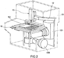
- Fig. 2 is a perspective view of the screening apparatus shown in Fig. 1
- the screening apparatus shown in Figs. 1 and 2 is merely an example, and the screening apparatus according to the present invention is not limited to that shown in Figs. 1 and 2 .
- the direction perpendicular to the plane of paper of Fig. 1 is defined as the X-direction
- the horizontal direction is defined as the Y-direction
- the direction perpendicular to the X-direction and the Y-direction is defined as the Z-direction.
- the screening apparatus 1 is an apparatus that searches for a predetermined cell as a target sample based on optical information emitted from a plurality of microparticles (e.g., cells of living) in a cell accommodating chip 60, and selectively sucks and picks up a cell in a well that accommodates a cell satisfying a collecting condition to collect the cell in an accommodating plate 50.
- a plurality of microparticles e.g., cells of living
- the screening apparatus 1 includes a base 11, a supporting section 12 (see Fig. 2 ), a collecting section 13, a measuring section 14, an image analyzing section 15, and a moving section 16, and, as shown in Fig. 2 , all the sections are covered with a cover 19 for preventing penetration of light and foreign substances from outside.
- the base 11 is a main body frame for holding each element of the screening apparatus 1.
- This base 11 includes plate members 111, 112, and 113 disposed substantially horizontally and holds the collecting section 13, the measuring section 14, and the moving section 16 via these plate members.
- the plate members 111 and 112 are fixed parallel to each other by a plurality of vertical members 114, and the plate members 112 and 113 are fixed parallel to each other by a plurality of vertical members 115.
- the vertical members 114 are made of a material shielding a vibration and are configured to be adjustable in height.
- the supporting section 12 and a supporting table 30 are fixed on the plate member 113 located at the uppermost position of the plurality of plate members.
- the supporting section 12 is arranged on the plate member 113 extending vertically along the Z-direction.
- the supporting table 30 includes a leg section 30a and a support plate 30b.
- the plate members 111, 112, and 113 and the support plate 30b are arranged with a predetermined interval therebetween in the Z-direction.
- the moving section 16 is mounted and secured on the support plate 30b of the supporting table 30.
- a mounting table 40, an accommodating plate 50, and a cell accommodating chip 60 are mounted on the moving section 16.
- the moving section 16 can move and position the mounting table 40, i.e., the accommodating plate 50 and the cell accommodating chip 60 mounted on the mounting table 40, along the X-direction and/or the Y-direction.
- Fig. 3 is a perspective view illustrating details of the moving section 16 and the mounting table 40 shown in Fig. 2 .
- the moving section 16 includes a table 161 and a table 162 arranged on said table.
- the table 161 is secured to the supporting table 30 and mounted so as to be capable of moving and positioning the table 162 along the X-direction.
- the table 162 is mounted so as to be capable of moving and positioning the mounting table 40 along the Y-direction.
- Guide rails 163, 163 and a motor 164 are disposed on the upper surface of the table 161.
- Engaging members 165, 165 having a U-shaped cross section and a nut 166 are disposed on the lower surface of the table 162.
- the engaging members 165, 165 are movably engaged with the guide rails 163, 163, respectively.
- a feed screw 167 of the motor 164 is screwed to the nut 166.
- the motor 164 is electrically connected to a control unit 100 and is operated in response to a command from the control unit 100 to rotate the feed screw 167. Consequently, the table 162 is moved and positioned along the X-direction.
- Guide rails 168, 168 and a motor 169 are disposed on the upper surface of the table 162.
- Engaging members 170, 170 having a U-shaped cross section and a nut 171 are disposed on the lower surface of the mounting table 40.
- the engaging members 170, 170 are movably engaged with the guide rails 168, 168, respectively.
- a feed screw 172 of the motor 169 is screwed to the nut 171.
- the motor 164 is electrically connected to the control unit 100 and is operated in response to a command from the control unit 100 to rotate the feed screw 172. Consequently, the mounting table 40 is moved and positioned in the Y-direction.
- the table 161 has an opening 173, the table 162 has an opening 174, and the mounting table 40 has an opening 175.
- These openings 173, 174, and 175 have respective sizes such that the openings always overlap each other even if the table 162 moves in the X-direction and the mounting table 40 moves in the Y-direction.
- the cells on the cell accommodating chip 60 on the mounting table 40 are irradiated with light L from the objective lens 110 side of the measuring section 14.
- the light L from the objective lens 110 side passes through the openings 173, 174, and 175 and irradiates the cells on the cell accommodating chip 60 on the mounting table 40. That is, it is possible to generate fluorescence from a cell and/or a well accommodating a cell at any relative position of the tables 161 and 162 and the mounting table 40.
- Fig. 4 is a perspective view illustrating structures of the accommodating plate 50 and the cell accommodating chip 60 on the mounting table 40 shown in Fig. 3 .
- the mounting table 40 is, for example, a rectangular plate-like member, and the accommodating plate 50 and the cell accommodating chip 60 are detachably mounted on a mounting surface 40a of the mounting table 40 sequentially in the Y-direction.
- the accommodating plate 50 is a plate-like member and is provided with a large number of wells 51 arranged at constant intervals along the X-direction and the Y-direction in a matrix form. These wells 51 form a collecting-and-storing section that can separately collect and store cells as target samples when the cells are sequentially ejected from a suction/discharge capillary 140.
- the wells 51 of the accommodating plate 50 are, for example, recessed portions having a substantially U-shaped vertical-direction cross section or recessed portions having a cup shape.
- the cell accommodating chip 60 is secured on the mounting surface 40a of the mounting table 40 by a securing member 120, and the securing member 120 is positioned at and fixed to a predetermined position of the mounting table 40.
- Fig. 5 is an enlarged cross-sectional view illustrating the structures of the cell accommodating chip 60 and the securing member 120.
- the securing member 120 is structured such that the cell accommodating chip 60 can be secured and held at a position of a reference plane CL at a certain height with respect to the mounting surface 40a of the mounting table 40.
- the securing member 120 includes frames 121 and 122 arranged so as to surround the edge of the cell accommodating chip 60 and holds the cell accommodating chip 60 in cooperation with these members.
- the cell accommodating chip 60 is arranged between the frames 121 and 122 in the Z-direction and is sandwiched between the frames 121 and 122 so as to be in pressure contact with each of the frames 121 and 122. Consequently, the sealing property between the cell accommodating chip 60 and the frame 121 is ensured.
- the upper surface 60b of the cell accommodating chip 60 is positioned at the reference plane CL via the frame 122. Consequently, it is possible to precisely control the distances in the Z-direction from the upper surface 60b of the cell accommodating chip 60 to the objective lens 110 of the measuring section 14 and to the accommodating plate 50. In other words, it possible to precisely control the position of a cell M in a well 61 of the cell accommodating chip 60 and the distance between the objective lens 110 of the measuring section 14 and the accommodating plate 50.
- the frame 121 includes a liquid-holding section 129 disposed at the central part in the plane direction of the frame and above the cell accommodating chip 60 and holding a liquid A and is thereby structured so as to be capable of holding each type of liquid, such as a medium, a reagent solution, and a reaction solution. That is, the liquid-holding section 129 is formed in an internal space of the frame 121.
- the frame 121 is openable with respect to the frame 122 by using, for example, a hinge mechanism section (not shown in the drawing), which allows the cell accommodating chip 60 in the securing member 120 to be taken out and be replaced with a new cell accommodating chip.
- the cell accommodating chip 60 is a plate-like member capable of accommodating a plurality of cells M. Detailed structure of the cell accommodating chip 60 will be described below.
- the collecting section 13 includes a suction/discharge capillary 140 for isolating the identified cell M as a target sample.
- the suction/discharge capillary 140 is a tapered hollow member whose diameter decreases along the Z2-direction (downward direction) and has a conduit 141 formed in the inside.
- the measuring section 14 irradiates a region including a plurality of wells 61 of the cell accommodating chip 60 with light L to generate fluorescence from a cell M and/or a well 61 accommodating a cell or in the vicinity thereof in the region, and receives the fluorescence.
- the fluorescence from the cell M and/or the well 61 accommodating a cell or in the vicinity thereof that received the light is subjected to image analysis by the image analyzing section 15.
- the measuring section 14 irradiates the cell accommodating chip 60 and cells M accommodated in the cell accommodating chip 60 with light guided from at least one light source and hence acquires shape and position information from transmitted light, reflected light, or fluorescence and brightness information, such as fluorescence and chemiluminescence, with a resolution finer than the average size of microparticles and also acquires information on, for example, the shape of the cell accommodating chip 60 itself and the positional coordinate and size of the wells 61 arranged on the cell accommodating chip 60.
- the measuring section 14 includes an objective lens 110, and the objective lens 110 guides light to the cell accommodating chip 60.
- the objective lens 110 is arranged below the cell accommodating chip 60 and the moving section 16, and the suction/discharge capillary 140 is arranged above the cell accommodating chip 60 and the moving section 16. That is, the cell accommodating chip 60 and the moving section 16 are arranged between the objective lens 110 and the suction/discharge capillary 140 in the Z-direction.
- the measuring section 14 includes an excitation light source 181 as a light source, an optical filter (excitation filter) 184 for selecting only a desired excitation wavelength band from light irradiated from the excitation light source 181, an optical filter (fluorescence filter) 185 for selecting only a desired wavelength band of optical information from the cell accommodating chip 60, a fluorescence filter unit 183 includes a dichroic mirror 186 for switching the optical path depending on the difference between the wavelength bands of the excitation light and the optical information, an objective lens 110 for guiding the light emitted from the excitation light source 181 to the cell accommodating chip 60 and collecting optical information obtained from the cell accommodating chip 60, a focus unit 187 having an automatic focus function capable of moving the objective lens 110 in the optical axis direction, and a light-receiving section 188 as a light-detecting section for detecting optical information from a measurement target.
- the fluorescence filter unit 183 and the light-receiving section 188 are fixed to an epifluorescence unit 190.
- the excitation light source 181 includes, for example, a laser light source or a mercury lamp.
- a shutter unit 182 is arranged between the excitation light source 181 and the fluorescence filter unit 183 and it is possible that the shutter unit 182 blocks light L produced by the excitation light source 181 before reaching the fluorescence filter unit 183 when the shutter unit 182 does not irradiate the cell M on the cell accommodating chip 60 with light L.
- the measuring section 14 includes a half mirror (not shown in the drawing), and by switching the half mirror and the fluorescence filter unit 183, irradiates an observation target with a part of the light from the excitation light source 181, and, at the same time, a part of the reflection light from the observation target is guided to the light-receiving section 188, which allows measurement of the shape and position information of the upper surface 60b of the cell accommodating chip 60 and the wells 61 formed on the upper surface.
- a plurality of objective lens 110a, 110b, ... are rotated, for example, in a revolve manner, and thereby an objective lens of a required magnification can be positioned below the cell accommodating chip 60.
- the focus unit 187 can perform focus adjustment of the objective lens 110 on a microparticle M on the cell accommodating chip 60 by, for example, operating the motor 189 in response to a command from the control unit 100 and moving and positioning, for example, the objective lens 110, disposed below the cell accommodating chip 60, along the Z-direction.
- the image analyzing section 15 calculates the fluorescent brightness of at least a cell M and/or a well 61 accommodating a cell or in the vicinity thereof emitting fluorescence of a maximum intensity among a plurality of cells M in the respective wells 61 and/or the wells 61 accommodating cells or in the vicinities thereof.
- the image analyzing section 15 acquires at least data for verifying the presence of a cell M satisfying a brightness condition, which can be set by an observer, in each well 61 by analyzing the measured shape information and optical information.
- the image analyzing section 15 extracts optical information from a cell M and/or a well 61 accommodating a cell or in the vicinity thereof by matching the positional coordinate information of the well 61 by transmitted light or reflected light and the optical information of fluorescence/chemiluminescence.
- the measuring section 14 has an automatic focus function and is capable of performing measurement while being focused at a predetermined position and capable of determining a positional relationship between the distal end of the suction/discharge capillary 140 and the upper surface of the cell accommodating chip 60 by automatically focusing on both of them.
- the control unit 100 detects, in an X-Y plane, the position of a well 61 emitting fluorescence having a brightness satisfying a collecting condition.
- the control unit 100 is capable of positioning a well 61 of the cell accommodating chip 60 on the moving section 16 directly below the suction/discharge capillary 140 by sending a control driving signal to the motors 164 and 169 shown in Fig. 3 . That is, the suction/discharge capillary 140 is configured so as to be capable of targeting a specific cell to suck the cell in the well.
- the suction/discharge capillary 140 is capable of sucking a single or a plurality of cells from a well selected from a plurality of wells, i.e., a well accommodating a cell satisfying a predetermined collecting condition. Furthermore, the suction/discharge capillary 140 is capable of discharging the sucked single or plurality of cells into a predetermined well 51 of the accommodating plate 50.
- Fig. 6 is a partial cross-sectional view illustrating the detailed structure of the cell accommodating chip 60 shown in Fig. 5 .
- the cell accommodating chip 60 includes a substrate 60a composed of a light-transmitting material and a plurality of wells 61, 61, ...,disposed on the upper surface 60b (at least one of main faces) of the substrate and capable of accommodating a plurality of cells M on one-to-one basis.
- the surface of the cell accommodating chip 60 may be configured so as not to have the coating layer, but a case in which a coating layer is formed will now be described in detail.
- the cell accommodating chip 60 includes a coating layer 62 formed on the inner surface 61a of each well constituting the plurality of wells 61, 61, ..., and on the upper surface 60b of the substrate 60a.
- the coating layer 62 may be formed on only the inner surface 61a of the well 61 or may be formed on both the inner surface 61a of the well 61 and the upper surface 60b of the substrate 60a.
- the cell accommodating chip 60 is composed of, for example, glass, plastic, or a material containing any of them as a main component, and a large number of wells 61 are arranged in, for example, a matrix form on the upper surface 60b.
- Each well 61 is a recessed portion having a vertical cross section of a substantially trapezoidal shape or a recessed portion having a substantially cup shape, and a horizontal cross-sectional shape of the well 61 is preferably substantially circular.
- the well 61 has a size corresponding to the accommodation of a single cell M when cells M are dispensed or collectively injected on the cell accommodating chip 60.
- the inner diameter and the depth of the well are each preferably slightly greater than the diameter of a cell, e.g., about 20 ⁇ m for a cell M having a diameter of 15 ⁇ m. It is preferable that the well 61 has a size corresponding to a single cell M and is more preferable that it has a size allowing only a single cell M to enter.
- the surface of the coating layer 62 has a low cell adhesion property to cells and has affinity to a specific binding material that has affinity to a produced substance produced by a cell M accommodated in a well 61 and/or a released substance released by a cell M accommodated in a well 61.
- the coating layer 62 includes, for example, a binding material that binds to a specific binding material having affinity to a produced substance produced by a cell M accommodated in a well 61 or a released substance released by a cell M accommodated in a well 61 and a low cell adhesive material having low adhesion to the cell M in the well 61.
- the surface of the coating layer 62 have hydrophilicity, a low cell adhesion property, and affinity to a specific binding material having affinity to a produced substance produced by a cell M accommodated in a well 61 and/or a released substance released by a cell M accommodated in a well 61.
- the coating layer 62 may include, for example, a hydrophilic material, a low cell adhesive material having low adhesion to a cell M in the well 61, and a binding material that binds to a specific binding material having affinity to a produced substance produced by the cell M accommodated in the well 61 and/or a released substance released by the cell M accommodated in the well 61.
- the low cell adhesive material having low adhesion to a cell M in a well 61 or the binding material that binds to a specific binding material having affinity to a produced substance produced by the cell M accommodated in the well 61 and/or a released substance released by the cell M accommodated in the well 61 may have hydrophilicity.
- the binding material be a functional group-containing material having at least one of functional groups described below or at least one selected from streptavidin, avidin, biotin, and derivatives thereof. Consequently, the binding material on the surface of the coating layer 62 binds to a specific binding material that binds to a produced substance produced by the cell accommodated in the well 61 or a released substance released by the cell accommodated in the well 61, and the specific binding material binds to the produced substance and/or the released substance.
- the low cell adhesive material constitutes a main component of the coating layer 62, and the binding material that binds to the specific binding material is uniformly distributed in the coating layer 62 in the in-plane direction of the coating layer 62.
- the low cell adhesive material is preferably, for example, a material having low protein adsorption to proteins.
- the hydrophilic material may constitute a main component of the coating layer 62 together with the low cell adhesive material or may be uniformly distributed in the coating layer 62 in the in-plane direction of the coating layer 62 together with the binding material that binds to the specific binding material.
- the hydrophilic material the binding material, and the low cell adhesive material contained in the coating layer 62 can be constituted in following combinations.
- the case where the binding material is a functional group-containing material will now be described as an example.
- an exemplary configuration may have a material having both hydrophilicity and a low cell adhesion property as a first material and a functional group-containing material as a second material.
- the first material may constitute a main component of the coating layer 62.
- an exemplary configuration may have a material having both hydrophilicity and a low cell adhesion property as a first material and a functional group-containing material having hydrophilicity as a second material
- an exemplary configuration may have a material having a low cell adhesion property as a first material and a functional group-containing material having hydrophilicity as a second material
- an exemplary configuration may have a material having a low cell adhesion property as a first material, a material having hydrophilicity as a second material, and a functional group-containing material as a third material.
- an exemplary configuration may have a material having a low cell adhesion property as a first material and a functional group-containing material as a second material.
- the hydrophilic material is a material having good wettability to a liquid containing cells M.
- the contact angle between distilled water and the coating layer 62 be 60° or less.
- the functional group-containing material have at least one functional group selected from an active ester group, an amino group, a carboxyl group, a thiol group, an aldehyde group, a hydrazino group, a hydroxylamino group, and a bromoacetyl group. Consequently, the functional group is chemically bound to the specific binding material, which allows the produced substance and/or the released substance to favorably bind to the coating layer 62 in the well 61.
- the binding material is streptavidin, avidin, biotin, or a derivative thereof
- the binding is achieved by affinity due to a chemical or physical factor other than covalent bonds.
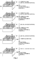
- Fig. 8 is a diagram including schematic views (a) to (e) for explaining a method for using the cell accommodating chip 60 structured as described above.
- a predetermined functional group 62a for example, an active ester group, of a functional group-containing material contained in the coating layer is bound to a specific binding material 81, such as a primary antibody ( Fig. 8(b) ).
- a coupling solution containing the specific binding material 81 that binds the predetermined functional group 62a and a produced substance m that is produced by a cell M to be accommodated in the well 61 is used, and the coupling solution is introduced on the cell accommodating chip 60. Consequently, the predetermined functional group 62a and the specific binding material 81 are bound to each other.
- the coupling solution is preferably alkaline and, specifically, preferably has a pH of 7 to 10.
- the specific binding material 81 e.g., a protein
- the specific binding material 81 is prevented from being damaged by denaturation or the like, and good binding between the predetermined functional group 62a and the produced substance m can be obtained.
- the specific binding material 81 is a binding substance that specifically binds to the produced substance.
- the specific binding material 81 is not limited to a primary antibody and may be an antigen or a substance other than protein.
- the specific binding material 81 used in the present invention is, for example, a chemical material such as a protein including cytokine, an immunoglobulin, an anti-immunoglobulin, and a hormone; or a chelating agent.
- a binding material capable of binding to the produced substance by a cell accommodated in a well 61 may be used instead of the specific binding material 81.
- an incubation medium containing a cell M is accommodated in the well 61, the cell M is incubated in the well 61 ( Fig. 8(c) ).
- the cell M generates a produced substance m, such as a produced antibody, by the incubation, and the produced substance m binds to the specific binding material 81 in the well 61 ( Fig. 8(d) ).
- the predetermined functional group 62a binds to the produced substance m via the specific binding material 81.
- the present invention can be applied to the identification of all cell types.
- the cell types are, for example, immune cell lines, such as B cells, T cells, and dendritic cells; cancer cell lines, such as CTC cells; stem cell lines, such as iPS cells and ES cells; hybridomas; CHO cells; and yeast cells.
- the produced substance is a protein, such as cytokine, an immunoglobulin, an anti-immunoglobulin, or a hormone; or a chemical material, such as a vitamin.
- a released substance which is a metal ion such as a calcium ion, released by a cell may be used.
- an optical information-holding substance 83 such as a fluorescent molecule (e.g., fluorescence-attached secondary antibody), specifically binding to the produced substance m or the specific binding material 81 is bound thereto ( Fig. 8(e) ).
- a fluorescent molecule e.g., fluorescence-attached secondary antibody
- the produced substance m produced by the cell M is bound to the specific binding material 81 bound onto the coating layer 62 in the well 61 accommodating the cell M; the optical information-holding substance 83 is bound to the produced substance m or the specific binding material 81; and the optical information of the optical information-holding substance 83 is detected. Consequently, it is possible to precisely identify a target sample using the well 61 as a marker, while maintaining the cell M and the produced substance m in the well 61 in a wet state.
- the screening apparatus 1 structured as described above collects a target sample using the above-described cell accommodating chip 60 as follows.
- Fig. 9 is a flow chart illustrating a screening method using the cell accommodating chip 60 shown in Fig. 8
- Fig. 10(a) to (d) are schematic views for explaining each step of Fig. 9 .
- a cell accommodating chip 60 configured as described above is prepared (Step S1), and a predetermined functional group 62a (see Fig. 8 ) contained in the coating layer 62 and a specific binding material 81 (binding material) having affinity to a produced substance m produced by the cell accommodated in a well 61 are bound to each other (Step S2) ( Fig. 10(a) ).
- a coupling solution containing a primary antibody is added dropwise or applied onto the coating layer 62 in the wells 61 to bind the primary antibody thereto.
- Step S3 may be performed between Step S1 and Step S2.
- a liquid e.g., incubation medium
- a liquid e.g., incubation medium
- the introduced liquid is left to stand for a predetermined period of time for waiting that each cell precipitates and enters into each well one by one.
- the cells M not accommodated in the wells 61 are removed by washing.
- the cell M accommodated in the well 61 is incubated to stimulate the production of a produced substance m, and the produced substance m produced by the cell M and the specific binding material 81 are bound to each other (Step S5).
- the cell incubation conditions e.g., temperature, type of gas, and concentration
- the incubation time of the cell M accommodated in the well 61 can be changed as needed.
- the produced substance m and the optical information-holding substance 83 having optical information, such as a fluorescent molecule, specifically binding to the produced substance m are bound to each other (Step S6) ( Fig. 10(c) ).
- the produced substance m or the specific binding material 81, and an optical information-holding substance 83 specifically binding thereto and having optical information, such as a fluorescent molecule, may be bound to each other.
- a solution containing a fluorescence-attached secondary antibody is added dropwise onto the cell accommodating chip 60, and this fluorescence-attached secondary antibody and the produced substance m are bound to each other.
- the optical information-holding substance 83 may be a functional group-attached fluorescent dye, a biotinated antibody + avidinated fluorescent dye, a fluorescent bead-attached secondary antibody, or the like, in addition to the fluorescence-attached secondary antibody.
- the treatment of Step S6 may be performed simultaneously with the treatment of Step S5. Subsequently, the top of the cell accommodating chip 60 and the insides of the wells 61 are washed, and the optical information-holding substance 83 not bound to the produced substance m or the specific binding material 81 is removed.
- Step S7 information on the reference position of the cell accommodating chip or a correction parameter is acquired as location information of the cell accommodating chip 60
- the center position coordinate information of each well is acquired by image analysis (Step S8).
- the cell accommodating chip 60 is irradiated with light, and the optical information of the optical information-holding substance 83 is acquired and is subjected to brightness analysis (Step S9).
- the optical information of the optical information-holding substance 83 fluorescent based on the photoirradiation in Step S9 may be acquired, or the optical information of the previously fluorescent optical information-holding substance 83 may be acquired.
- As the brightness analysis a change with time of the fluorescent information obtained from the optical information-holding substance 83 may be measured.
- a collecting condition of microparticles desired by a user may be, for example, the brightness of a fluorescence is higher than a predetermined threshold value, or the brightness of at least one of the fluorescences is higher than a predetermined threshold value in the case a plurality of fluorescence (e.g., different fluorescent colors) are used, or any combination thereof.
- the brightness of any fluorescence may be combined with those excluded from the collection (those lower than a threshold value).
- the center position of the suction/discharge capillary 140 is acquired by, for example, image analysis, and the center position or a position shifted from the center position by a predetermined distance is set as the center position (position information) of each well in the cell collection (Step S12).
- the center position of the well 61 accommodating the target sample is moved so as to fit the center position of the well set in Step S12, and target samples identified in Step S11 are sequentially collected (Step S13) ( Fig. 10(d) ).
- the collected target samples are accommodated in predetermined wells 51 on the accommodating plate 50 set by the user in advance.
- Fig. 11 is a graph showing the results in measurement and comparison of contact angles between a variety of cell accommodating chips and distilled water.
- a coating layer containing a first material having both hydrophilicity and low protein adsorption, and a second material which is a functional group-containing material was used. Specifically, a PEG derivative was used as a first material, and a material having an active ester group was used as a second material.
- a coating layer containing only a functional group-containing material was used; as a Comparative Example Sample 2, a coating layer containing only a hydrophilic material was used; and as a Comparative Example Sample 3, an untreated cell accommodating chip that does not have a coating layer was used. In all samples, the material and shape of the substrates and the method for producing the substrates were the same.
- the contact angle was measured in accordance with JIS R3257 and the contact angle was calculated by a static method as shown below.
- the contact angle ⁇ (°) was determined from the radius r (mm) and the height h (mm) when 1 ⁇ L of distilled water was dropped onto a cell accommodating chip.
- the radius r is a radius of the surface of the water drop in contact with the chip surface
- the height h is a height from the chip surface to the top of the water drop. The average value when 6 points were measured per sample was calculated.
- Example Sample 1 when the coating layer contains a functional group-containing material only (Comparative Example Sample 1), the contact angle between the coating layer and distilled water is 69° to 75°, and the average value is 72°.
- the coating layer of the present invention contains a material having both hydrophilicity and low protein adsorption and a functional group-containing material, and the contact angle is 44° to 53°, an average value is 50°, and it is demonstrated that the hydrophilicity has been considerably improved.
- the coating layer contains a hydrophilic material only (Comparative Example Sample 2)
- the contact angle between the cell accommodating chip and a liquid containing cells is 14° to 17°, an average value is 15°, it is difficult to bind a specific binding material having affinity to a produced substance, and the cell accommodated in the well and proteins such as the produced substance could adsorb to the coating layer.
- the contact angle is 78° to 86°, an average value is 83°, and the wettability is obviously low.
- the hydrophilicity of the cell accommodating chip containing the wells highly affects the inflow of a liquid containing cells into the wells. Accordingly, in order to verify and evaluate the influence of the contact angle of the cell accommodating chip on the bubble ratio occurring in the wells, which is an index of hydrophilicity, the following test was performed.
- each of the cell accommodating chips was set in a securing member, PBS (phosphate buffered saline) of ordinary temperature was introduced on the cell accommodating chip, and the proportion of the number of wells having bubbles therein in random 500 wells on the chip was determined as a bubble ratio.
- the same Example Sample and Comparative Example Samples as those in the evaluation of hydrophilicity were used. The results are shown in Table 1.
- the bubble ratios (1) to (3) of the wells were all 0%, wells having bubbles were not found immediately after introduction of PBS and also after an elapse of a predetermined time.
- the bubble ratios (1) to (3) of the wells were all 100%, bubbles were formed in all wells immediately after introduction of PBS, and the bubbles remained in all wells even after an elapse of a predetermined time.
- a liquid containing the cells (also referred to as cell suspension) is introduced on the cell accommodating chip and is left to stand, and the cells then slowly precipitate in the liquid and are accommodated in the wells.
- the surface of the cell accommodating chip and the surface of the well is low, bubbles are produced in the well, the progress of precipitation of the cell is prevented by the bubbles in the well, and it is impossible to accommodate the cell in the well. Accordingly, the surface of the cell accommodating chip needs to have hydrophilicity that allows bubbles in the well to escape before the cell precipitates in the liquid.
- the contact angle of the surface of the cell accommodating chip is 60° or less, the surface of the cell accommodating chip has the sufficient hydrophilicity for suppressing the retention of bubbles in the well, and a cell can be positively accommodated in the fine well.
- the measurement and evaluation of the adhesion rates of cells were performed as follows. As shown in Fig. 9 , firstly, a primary antibody-containing coupling solution was added dropwise onto each of the cell accommodating chips to bind the primary antibody. Subsequently, the surface of the cell accommodating chip was washed to remove the unbound primary antibody and the components of the coupling solution. After the washing, each of the cell accommodating chips was set to the securing member, an incubation medium containing a plurality of 293T cells was introduced on the cell accommodating chip, and the plurality of cells were accommodated in a plurality of wells on a cell basis. Subsequently, the cells not accommodated in the wells were removed by washing.
- the cell accommodating chip and the cells accommodated in the wells are incubated for 60 minutes, and when the 48 cells stored in the wells on the cell accommodating chip were tried to be collected with a cell-screening apparatus including a collection mechanism, the proportion of the cells that adhered to the surface of the cell accommodating chip and could not be collected was defined as the adhesion rate.
- Example Sample and Comparative Example Samples 1 and 2 as those in aforementioned evaluation of hydrophilicity were used. The results are shown in Table 2.
- Example Sample 2 As shown in Table 2, it is demonstrated that in the case of the coating layer of the present embodiment (Example Sample), the adhesion rate of 293T cells was about 4% (two cells), and most of the 293T cells did not adhere to the coating layer. In contrast, it is demonstrated that in the case of the coating layer containing the functional group-containing material only (Comparative Example Sample 1), the adhesion rate of the 293T cells was about 96% (46 cells), and most of the cells adhered to the coating layer. It is also demonstrated that in the case of the coating layer containing the hydrophilic material only (Comparative Example Sample 2), the adhesion rate was about 83% (40 cells), and most of the cells adhered to the coating layer.
- the adhesion rate of cells to the coating layer is remarkably low, the coating layer in a well hardly adheres to the cell accommodated in the well, and favorable a low cell adhesion property can be achieved.
- the surface of the coating layer 62 in a plurality of wells 61 has a low cell adhesion property and has affinity to the specific binding material 81 having affinity to the produced substance m produced by the cell M accommodated in the well 61.
- the liquid containing cells M can easily enter fine wells 61 by means of the hydrophilic material of the coating layer 62, the accuracy of accommodating a single cell in each well can be enhanced, and the accuracy and efficiency of identifying and isolating a target sample can be improved.
- the surface of the coating layer 62 has affinity to the specific binding material 81, and thereby there is no need to bind the specific binding material 81 having affinity to the produced substance m on the cell accommodating chip 60 in advance, and the reduction in accuracy due to drying or the like can be prevented.
- the inside of the well 61 is hardly dried by the hydrophilicity of the coating layer 62 compared to conventional one, the inside of the well 61 can be kept wet even after binding of the specific binding material 81, and a reduction in accuracy due to drying or the like of the specific binding material 81 can be prevented.
- the specific binding material 81 binds to the predetermined functional group 62a by the affinity of the surface of the coating layer 62 to the specific binding material 81, and the produced substance m produced by the cell M in the well 61 of the coating layer 62 binds to the specific binding material 81. Accordingly, the well 61 itself can be used as a labeling site in identification of a target sample, and the target sample can be identified without damaging the cell M.
- the surface of the coating layer 62 has a low cell adhesion property, the cell M in the well 61 can be prevented from adhering to the inner surface of the well and the upper surface 60b of the substrate 60a, the cell M as a target sample can be collected at high efficiency without requiring coating treatment using a blocking reagent or the like, and when collecting cells, the cell M can be collected without being damaged.
- the coating layer 62 contains a low protein adsorption material, when the produced substance m is a protein, nonspecific adsorption of the produced substance m to the surface of the cell accommodating chip is prevented, and good detection sensitivity can be maintained without requiring coating treatment using a blocking reagent or the like.
- a cell accommodating chip 60 including a coating layer 62 having a surface that has a low cell adhesion property and affinity to a specific binding material 81 having affinity to a produced substance m produced by a cell M accommodated in a well 61 is prepared; and a specific binding material 81 is bound to the surface of the coating layer 62, a liquid containing a plurality of cells M is introduced to the cell accommodating chip 60 to accommodate the plurality of cells M in a plurality of wells 61 on a cell basis to bind the produced substance m from the cell M accommodated in the well 61 to the specific binding material 81, which allows the produced substance m or the specific binding material 81 to bind an optical information-holding substance 83 having optical information. It is therefore possible to identify and isolate the target sample with high accuracy and high efficiency. In addition, with simple handling, easy collection without damaging cells M in cell collection can be achieved.
- a cell accommodating chip, a screening apparatus, and a screening method according to the present embodiment have been described above.
- the present invention is not limited to the above-described embodiments and can be variously modified and altered based on the technical idea of the present invention.
- the cell M accommodated in a well 61 emitting light with brightness satisfying the collecting condition is identified as a target sample (Step S11). That is, in Figs. 9 and 10 , an optical information-holding substance 83 that specifically binds to the produced substance m (white Y in Fig. 10 ) that is secreted from the cell M is used, and the produced substance m produced by the cell M binds to the well 61 in which the cell M is accommodated. Accordingly, as described above, the timing of binding the optical information-holding substance 83 to the specific binding material 81 (Step S6) can be after Step S5 or simultaneous with Step S5.
- a screening method for identifying, as a target sample, the cell M accommodated in a well 61 other than the wells emitting light with brightness not lower than the threshold used in the above-described collecting condition may be used.
- description of the same parts as those in the flow chart shown in Fig. 9 will be omitted, and different parts will be described.
- a plurality of cells M is accommodated in a plurality of wells 61 on a cell-by-cell basis (Step S4), and then each cell is incubated to stimulate the production of a produced substance m to bind the produced substance m produced by the cell M to the specific binding material 81 in the well 61 (Step S5). Consequently, the specific binding material 81 in the well 61 accommodating the cell M as a target sample is covered with the produced substance m, and the specific binding material 81 in the well 61 not accommodating the cell M as a target sample is not covered with the produced substance m.
- Step S6' another optical information-holding substance not specifically binding to the produced substance m but specifically binding to the specific binding material 81 is used, and the another optical information-holding substance is bound to the specific binding material 81 (Step S6'). Consequently, the well 61 accommodating a cell M producing the produced substance m does not emit light, and the well 61 accommodating a cell M not producing the produced substance m emits light. Accordingly, in this method, Step S5 and Step S6' are not simultaneously performed, and Step S6' is performed after Step S5.
- the optical information of the optical information-holding substance 83 is acquired and is subjected to brightness analysis (Step S9).
- a collecting condition of microparticles desired by a user is input (Step S10), and based on the collecting condition, a cell M is identified as a target sample (Step S11).
- the collecting condition is that light is not emitted or that the brightness is not higher than a predetermined threshold, and the cell M accommodated in a well 61 satisfying the collecting condition is identified as a target sample.
Landscapes
- Health & Medical Sciences (AREA)
- Chemical & Material Sciences (AREA)
- Life Sciences & Earth Sciences (AREA)
- Engineering & Computer Science (AREA)
- Organic Chemistry (AREA)
- Zoology (AREA)
- Wood Science & Technology (AREA)
- Bioinformatics & Cheminformatics (AREA)
- General Health & Medical Sciences (AREA)
- Biomedical Technology (AREA)
- Biochemistry (AREA)
- Microbiology (AREA)
- Biotechnology (AREA)
- Sustainable Development (AREA)
- General Engineering & Computer Science (AREA)
- Genetics & Genomics (AREA)
- Clinical Laboratory Science (AREA)
- Analytical Chemistry (AREA)
- Hematology (AREA)
- Immunology (AREA)
- Molecular Biology (AREA)
- Urology & Nephrology (AREA)
- Chemical Kinetics & Catalysis (AREA)
- Pathology (AREA)
- Food Science & Technology (AREA)
- Medicinal Chemistry (AREA)
- Physics & Mathematics (AREA)
- General Physics & Mathematics (AREA)
- Dispersion Chemistry (AREA)
- Tropical Medicine & Parasitology (AREA)
- Cell Biology (AREA)
- Apparatus Associated With Microorganisms And Enzymes (AREA)
- Addition Polymer Or Copolymer, Post-Treatments, Or Chemical Modifications (AREA)
- Measuring Or Testing Involving Enzymes Or Micro-Organisms (AREA)
- Sampling And Sample Adjustment (AREA)
Abstract
Description
- The present invention relates to a cell accommodating chip capable of accommodating a plurality of cells in screening for a target sample and a screening method using the cell accommodating chip, and particularly relates to a cell accommodating chip for detecting a cell to be a target sample by irradiating wells and cells with light and based on fluorescence emitted by a substance bound on the cell accommodating chip and selectively sucking and collecting the cell, as well as a screening method using the cell accommodating chip.
- Conventionally, screening apparatuses have been widely used as apparatuses for identifying and isolating minute analytes, such as cells, in research, inspection, and so on in the medical field. In recent years, in the research and inspection institutions, there are demands for achieving identification and isolation without destroying analytes and for increasing the efficiency of research and inspection by more exactly performing these treatments. In particular, in a predetermined field, since there is a growing demand for identifying and isolating, on a single cell basis, a specific cell from a large number of cells, improvement of accuracy and enhancement of efficiency are required also in such identification and isolation treatments on a single cell basis.
- In identification and isolation treatments of cells performed with a nondestructive manner, it is desirable to retain a medium containing a large number of fine particles on a cell accommodating chip such that a target sample and a nontarget sample are clearly distinguished from each other. Accordingly, conventionally, for example, a method for identifying a target sample using a microwell array chip including a coating layer prepared by binding an anti-immunoglobulin (Ig) antibody to a part of an upper surface of the chip, dispensing an antibody-secreting cells to each well of the microwell array chip to bind an antibody secreted from at least some of the cells accommodated in the well to the anti-Ig antibody of the coating layer, and detecting the secreted antibody with a fluorescence-labeled antigen is disclosed (Patent Literature 1).
- In addition, in order to selectively bind a desired target sample from an external environment or collectively remove nontarget samples from a surface, a functional coating prepared by supplying, to a plate-like support, a low nonspecific binding matrix immobilized on the support and an active component covalently bonded in the nonspecific binding matrix by physically entangling is disclosed (Patent Literature 2).
-
- Patent Literature 1: Japanese Patent No.
4148367 - Patent Literature 2: National Publication of International Patent Application No.
2004-531390 - However, with the technique of
Patent Literature 1, since the chip upper surface must be kept wet during the period from binding of an anti-Ig antibody to a part of the chip upper surface until identification of the target sample, the anti-Ig antibody cannot be sustained for a long time. In addition, since a cell may adhere to an inner surface of a well during antibody secretion by the cell, it is difficult to collect the cell, and even if the cell was collected, it is very likely to damage the cell that is a target sample. - In addition,
Patent Literature 2 discloses a structure in which a target sample is selectively bound to a functional coating disposed on an upper surface of a plate-like support, but not a structure retaining a single cell in each well, and it cannot be said that the accuracy and efficiency of identification and isolation of a specific cell on a cell basis are high. - It is an object of the present invention is to provide a cell accommodating chip that can identify and isolate a target sample with high accuracy and high efficiency, that can be simply handled, and that allows easy collection without damaging the cell, and to provide a screening method using the cell accommodating chip.
- In order to achieve the object, the cell accommodating chip of the present invention is a cell accommodating chip accommodating a plurality of cells and is characterized by comprising a substrate composed of a light-transmitting material and a plurality of wells on at least one of main faces of the substrate, the plurality of wells being capable of accommodating cells, wherein a surface of the cell accommodating chip including the plurality of wells has a low cell adhesion property and has affinity to a specific binding material having affinity to a produced substance produced by a cell accommodated in one of the wells and/or a released substance released by the cell.
- It is preferable that each of the wells has a size corresponding to the accommodation of a single cell.
- It is preferable that the surface of the cell accommodating chip further have hydrophilicity.
- The chip may have a coating layer on the substrate, and the coating layer may have a low cell adhesion property and affinity to a specific binding material having affinity to a produced substance produced by a cell accommodated in one of the wells and/or a released substance released by the cell.
- In addition, the chip may have a coating layer on the substrate, and a surface of the coating layer may have hydrophilicity, a low cell adhesion property, and affinity to a specific binding material having affinity to a produced substance produced by a cell accommodated in one of the wells and/or a released substance released by the cell.
- It is preferable that the coating layer having the low cell adhesion property be a coating layer including a low cell adhesive material.
- It is preferable that the low cell adhesive material be a low protein adsorption material.
- It is preferable that the coating layer having affinity to the specific binding material be a coating layer including a binding material having affinity to the specific binding material.
- It is preferable that the coating layer having the hydrophilicity be a coating layer including a hydrophilic material.
- It is preferable that the contact angle of the surface of the cell accommodating chip be less than or equal to 60°.
- It is preferable that the binding material be a functional group-containing material having at least one functional group selected from an active ester group, an amino group, a carboxyl group, a thiol group, an aldehyde group, a hydrazino group, a hydroxylamino group, and a bromoacetyl group.
- The binding material may be at least one selected from streptavidin, avidin, biotin, and derivatives thereof.
- It is preferable that the low protein adsorption material be a polymer compound.
- It is preferable that the cell accommodating chip be used in a screening apparatus for searching for a predetermined cell based on optical information emitted from a substance on the cell accommodating chip and selectively picking up the cell searched for.
- In order to achieve the object, the screening method of the present invention is a screening method for searching for a predetermined cell based on optical information emitted from a substance on a cell accommodating chip and selectively picking up the cell searched for and is characterized by comprising a preparation step of preparing a cell accommodating chip having a plurality of wells disposed on a substrate composed of a light-transmitting material and having a surface having a low cell adhesion property and affinity to a specific binding material having affinity to a produced substance produced by a cell accommodated in one of the wells and/or a released substance released by the cell; a first binding step of binding the specific binding material to the surface of the cell accommodating chip; a cell accommodating step of introducing a liquid containing a plurality of cells to the cell accommodating chip and accommodating the plurality of cells in the plurality of wells on a cell-by-cell basis; a second binding step of binding a produced substance and/or a released substance by the cell accommodated in one of the wells to the specific binding material; a third binding step of binding the produced substance or the released substance or the specific binding material to an optical information-holding substance having optical information; a measurement step of measuring the optical information of the optical information-holding substance; and an identification/collection step of identifying and collecting a cell as a target sample from the plurality of cells based on the measurement result in the measurement step.
- According to the present invention, a surface of a cell accommodating chip having a plurality of wells has a low cell adhesion property and also has affinity to a specific binding material having affinity to a produced substance that is produced by a cell accommodated in any of the wells and/or a released substance that is released by said cell. Since a conventional chip has a structure in which a substance having affinity to a produced substance or a released substance is bound on the chip in advance, it is difficult to preserve the chip for a long period of time, and the accuracy may decrease due to drying or the like. In contrast, according to the present invention, since the surface of the cell accommodating chip has affinity to the specific binding material, it is not necessary to bind a specific binding material having affinity to a produced substance and/or a released substance on the cell accommodating chip in advance, and a reduction in accuracy due to drying or the like can be prevented. In addition, due to the affinity of the surface of the cell accommodating chip to the specific binding material, the specific binding material binds to the surface of the cell accommodating chip having wells, and a produced substance that is produced by a cell in any of the wells and/or a released substance that is released by said cell binds to the specific binding material. Accordingly, the well itself can be used as a labeling site in identification of a target sample, and the target sample can be identified without damaging the cell. Furthermore, since the surface of the cell accommodating chip has a low cell adhesion property, the cell in the well can be prevented from adhering to the surface of the cell accommodating chip, the cell that is a target sample can be collected at high efficiency without requiring coating treatment using a blocking reagent or the like, and in cell collection, the cell can be collected without being damaged.
- In addition, according to the present invention, a cell accommodating chip having a surface that has a low cell adhesion property and affinity to a specific binding material having affinity to a produced substance produced and/or a released substance released by a cell accommodated in a well is prepared; and a specific binding material is bound to the surface of the cell accommodating chip, a liquid containing a plurality of cells is introduced to the cell accommodating chip to accommodate the plurality of cells in a plurality of wells on a cell-by-cell basis to bind the produced substance and/or the released substance by the cell accommodated in the well to the specific binding material, which allows the produced substance or released substance or the specific binding material to bind an optical information-holding substance having optical information. It is therefore possible to identify and isolate the target sample with high accuracy and high efficiency. In addition, with simple handling, easy collection can be achieved without damaging the cells during cell collection.
-
- [
Fig. 1] Fig. 1 is a side view schematically illustrating a structure of a screening apparatus according to an embodiment of the present invention. - [
Fig. 2] Fig. 2 is a perspective view of the screening apparatus ofFig. 1 . - [
Fig. 3] Fig. 3 is a perspective view illustrating details of a moving section and a mounting table shown inFig. 2 . - [
Fig. 4] Fig. 4 is a perspective view illustrating a structure of the mounting table shown inFig. 3 . - [
Fig. 5] Fig. 5 is an enlarged cross-sectional view illustrating the structures of a cell accommodating chip and a securing member of the cell accommodating chip. - [
Fig. 6] Fig. 6 is a partial cross-sectional view illustrating the detailed structure of the cell accommodating chip shown inFig. 5 . - [
Fig. 7] Fig. 7 is a diagram including schematic views (a) to (e) illustrating examples of the combination of a hydrophilic material, a functional group-containing material, and a low cell adhesive material contained in a coating layer formed on the inner surfaces of the wells shown inFig. 6 . - [
Fig. 8] Fig. 8 is a diagram including schematic views (a) to (e) for explaining a method for using the cell accommodating chip shown inFig. 6 . - [
Fig. 9] Fig. 9 is a flow chart illustrating a screening method using the cell accommodating chip shown inFig. 8 . - [
Fig. 10] Fig. 10 is a diagram including schematic views (a) to (d) for explaining each step ofFig. 9 . - [
Fig. 11] Fig. 11 is a graph showing the results in measurement and comparison of contact angles between a variety of cell accommodating chips and distilled water. - [
Fig. 12] Fig. 12 is a flow chart illustrating a modified example of the screening method shown inFig. 9 . - Embodiments of the present invention will now be described in detail referring to the drawings.
-
Fig. 1 is a side view schematically illustrating a structure of a screening apparatus according to the present embodiment, andFig. 2 is a perspective view of the screening apparatus shown inFig. 1 . The screening apparatus shown inFigs. 1 and2 is merely an example, and the screening apparatus according to the present invention is not limited to that shown inFigs. 1 and2 . For convenience of explanation, the direction perpendicular to the plane of paper ofFig. 1 is defined as the X-direction, the horizontal direction is defined as the Y-direction, and the direction perpendicular to the X-direction and the Y-direction is defined as the Z-direction. - In
Figs. 1 and2 , thescreening apparatus 1 is an apparatus that searches for a predetermined cell as a target sample based on optical information emitted from a plurality of microparticles (e.g., cells of living) in acell accommodating chip 60, and selectively sucks and picks up a cell in a well that accommodates a cell satisfying a collecting condition to collect the cell in anaccommodating plate 50. - Specifically, the
screening apparatus 1 includes abase 11, a supporting section 12 (seeFig. 2 ), acollecting section 13, ameasuring section 14, animage analyzing section 15, and a movingsection 16, and, as shown inFig. 2 , all the sections are covered with acover 19 for preventing penetration of light and foreign substances from outside. - The
base 11 is a main body frame for holding each element of thescreening apparatus 1. Thisbase 11 includesplate members section 13, the measuringsection 14, and the movingsection 16 via these plate members. Theplate members vertical members 114, and theplate members vertical members 115. Thevertical members 114 are made of a material shielding a vibration and are configured to be adjustable in height. - The supporting
section 12 and a supporting table 30 are fixed on theplate member 113 located at the uppermost position of the plurality of plate members. The supportingsection 12 is arranged on theplate member 113 extending vertically along the Z-direction. The supporting table 30 includes aleg section 30a and asupport plate 30b. Theplate members support plate 30b are arranged with a predetermined interval therebetween in the Z-direction. - The moving
section 16 is mounted and secured on thesupport plate 30b of the supporting table 30. A mounting table 40, anaccommodating plate 50, and acell accommodating chip 60 are mounted on the movingsection 16. The movingsection 16 can move and position the mounting table 40, i.e., theaccommodating plate 50 and thecell accommodating chip 60 mounted on the mounting table 40, along the X-direction and/or the Y-direction. -
Fig. 3 is a perspective view illustrating details of the movingsection 16 and the mounting table 40 shown inFig. 2 . - As shown in
Fig. 3 , the movingsection 16 includes a table 161 and a table 162 arranged on said table. The table 161 is secured to the supporting table 30 and mounted so as to be capable of moving and positioning the table 162 along the X-direction. The table 162 is mounted so as to be capable of moving and positioning the mounting table 40 along the Y-direction. -
Guide rails motor 164 are disposed on the upper surface of the table 161. Engagingmembers nut 166 are disposed on the lower surface of the table 162. The engagingmembers guide rails feed screw 167 of themotor 164 is screwed to thenut 166. - The
motor 164 is electrically connected to acontrol unit 100 and is operated in response to a command from thecontrol unit 100 to rotate thefeed screw 167. Consequently, the table 162 is moved and positioned along the X-direction. -
Guide rails motor 169 are disposed on the upper surface of the table 162. Engagingmembers nut 171 are disposed on the lower surface of the mounting table 40. The engagingmembers guide rails feed screw 172 of themotor 169 is screwed to thenut 171. - The
motor 164 is electrically connected to thecontrol unit 100 and is operated in response to a command from thecontrol unit 100 to rotate thefeed screw 172. Consequently, the mounting table 40 is moved and positioned in the Y-direction. - The table 161 has an
opening 173, the table 162 has anopening 174, and the mounting table 40 has anopening 175. Theseopenings openings cell accommodating chip 60 on the mounting table 40 are irradiated with light L from theobjective lens 110 side of the measuringsection 14. - In addition, even if the table 162 moves in the X-direction and the mounting table 40 moves in the Y-direction, the light L from the
objective lens 110 side passes through theopenings cell accommodating chip 60 on the mounting table 40. That is, it is possible to generate fluorescence from a cell and/or a well accommodating a cell at any relative position of the tables 161 and 162 and the mounting table 40. -
Fig. 4 is a perspective view illustrating structures of theaccommodating plate 50 and thecell accommodating chip 60 on the mounting table 40 shown inFig. 3 . - The mounting table 40 is, for example, a rectangular plate-like member, and the
accommodating plate 50 and thecell accommodating chip 60 are detachably mounted on a mountingsurface 40a of the mounting table 40 sequentially in the Y-direction. - The
accommodating plate 50 is a plate-like member and is provided with a large number ofwells 51 arranged at constant intervals along the X-direction and the Y-direction in a matrix form. Thesewells 51 form a collecting-and-storing section that can separately collect and store cells as target samples when the cells are sequentially ejected from a suction/discharge capillary 140. Thewells 51 of theaccommodating plate 50 are, for example, recessed portions having a substantially U-shaped vertical-direction cross section or recessed portions having a cup shape. - The
cell accommodating chip 60 is secured on the mountingsurface 40a of the mounting table 40 by a securingmember 120, and the securingmember 120 is positioned at and fixed to a predetermined position of the mounting table 40. -
Fig. 5 is an enlarged cross-sectional view illustrating the structures of thecell accommodating chip 60 and the securingmember 120. As shown in the drawing, the securingmember 120 is structured such that thecell accommodating chip 60 can be secured and held at a position of a reference plane CL at a certain height with respect to the mountingsurface 40a of the mounting table 40. Specifically, the securingmember 120 includesframes cell accommodating chip 60 and holds thecell accommodating chip 60 in cooperation with these members. - The
cell accommodating chip 60 is arranged between theframes frames frames cell accommodating chip 60 and theframe 121 is ensured. - In the state in which the
cell accommodating chip 60 is being in pressure contact with theframe 121, theupper surface 60b of thecell accommodating chip 60 is positioned at the reference plane CL via theframe 122. Consequently, it is possible to precisely control the distances in the Z-direction from theupper surface 60b of thecell accommodating chip 60 to theobjective lens 110 of the measuringsection 14 and to theaccommodating plate 50. In other words, it possible to precisely control the position of a cell M in a well 61 of thecell accommodating chip 60 and the distance between theobjective lens 110 of the measuringsection 14 and theaccommodating plate 50. - The
frame 121 includes a liquid-holdingsection 129 disposed at the central part in the plane direction of the frame and above thecell accommodating chip 60 and holding a liquid A and is thereby structured so as to be capable of holding each type of liquid, such as a medium, a reagent solution, and a reaction solution. That is, the liquid-holdingsection 129 is formed in an internal space of theframe 121. Theframe 121 is openable with respect to theframe 122 by using, for example, a hinge mechanism section (not shown in the drawing), which allows thecell accommodating chip 60 in the securingmember 120 to be taken out and be replaced with a new cell accommodating chip. Thecell accommodating chip 60 is a plate-like member capable of accommodating a plurality of cells M. Detailed structure of thecell accommodating chip 60 will be described below. - The collecting
section 13 includes a suction/discharge capillary 140 for isolating the identified cell M as a target sample. The suction/discharge capillary 140 is a tapered hollow member whose diameter decreases along the Z2-direction (downward direction) and has aconduit 141 formed in the inside. - Returning to
Fig. 1 , the measuringsection 14 irradiates a region including a plurality ofwells 61 of thecell accommodating chip 60 with light L to generate fluorescence from a cell M and/or a well 61 accommodating a cell or in the vicinity thereof in the region, and receives the fluorescence. The fluorescence from the cell M and/or the well 61 accommodating a cell or in the vicinity thereof that received the light is subjected to image analysis by theimage analyzing section 15. - Specifically, the measuring
section 14 irradiates thecell accommodating chip 60 and cells M accommodated in thecell accommodating chip 60 with light guided from at least one light source and hence acquires shape and position information from transmitted light, reflected light, or fluorescence and brightness information, such as fluorescence and chemiluminescence, with a resolution finer than the average size of microparticles and also acquires information on, for example, the shape of thecell accommodating chip 60 itself and the positional coordinate and size of thewells 61 arranged on thecell accommodating chip 60. - The measuring
section 14 includes anobjective lens 110, and theobjective lens 110 guides light to thecell accommodating chip 60. Theobjective lens 110 is arranged below thecell accommodating chip 60 and the movingsection 16, and the suction/discharge capillary 140 is arranged above thecell accommodating chip 60 and the movingsection 16. That is, thecell accommodating chip 60 and the movingsection 16 are arranged between theobjective lens 110 and the suction/discharge capillary 140 in the Z-direction. - The measuring
section 14 includes anexcitation light source 181 as a light source, an optical filter (excitation filter) 184 for selecting only a desired excitation wavelength band from light irradiated from theexcitation light source 181, an optical filter (fluorescence filter) 185 for selecting only a desired wavelength band of optical information from thecell accommodating chip 60, afluorescence filter unit 183 includes adichroic mirror 186 for switching the optical path depending on the difference between the wavelength bands of the excitation light and the optical information, anobjective lens 110 for guiding the light emitted from theexcitation light source 181 to thecell accommodating chip 60 and collecting optical information obtained from thecell accommodating chip 60, afocus unit 187 having an automatic focus function capable of moving theobjective lens 110 in the optical axis direction, and a light-receivingsection 188 as a light-detecting section for detecting optical information from a measurement target. Thefluorescence filter unit 183 and the light-receivingsection 188 are fixed to anepifluorescence unit 190. - The
excitation light source 181 includes, for example, a laser light source or a mercury lamp. Ashutter unit 182 is arranged between theexcitation light source 181 and thefluorescence filter unit 183 and it is possible that theshutter unit 182 blocks light L produced by theexcitation light source 181 before reaching thefluorescence filter unit 183 when theshutter unit 182 does not irradiate the cell M on thecell accommodating chip 60 with light L. - Furthermore, the measuring
section 14 includes a half mirror (not shown in the drawing), and by switching the half mirror and thefluorescence filter unit 183, irradiates an observation target with a part of the light from theexcitation light source 181, and, at the same time, a part of the reflection light from the observation target is guided to the light-receivingsection 188, which allows measurement of the shape and position information of theupper surface 60b of thecell accommodating chip 60 and thewells 61 formed on the upper surface. - In the measuring
section 14, a plurality ofobjective lens cell accommodating chip 60. Thefocus unit 187 can perform focus adjustment of theobjective lens 110 on a microparticle M on thecell accommodating chip 60 by, for example, operating themotor 189 in response to a command from thecontrol unit 100 and moving and positioning, for example, theobjective lens 110, disposed below thecell accommodating chip 60, along the Z-direction. - The
image analyzing section 15 calculates the fluorescent brightness of at least a cell M and/or a well 61 accommodating a cell or in the vicinity thereof emitting fluorescence of a maximum intensity among a plurality of cells M in therespective wells 61 and/or thewells 61 accommodating cells or in the vicinities thereof. - Specifically, the
image analyzing section 15 acquires at least data for verifying the presence of a cell M satisfying a brightness condition, which can be set by an observer, in each well 61 by analyzing the measured shape information and optical information. Theimage analyzing section 15 extracts optical information from a cell M and/or a well 61 accommodating a cell or in the vicinity thereof by matching the positional coordinate information of the well 61 by transmitted light or reflected light and the optical information of fluorescence/chemiluminescence. The measuringsection 14 has an automatic focus function and is capable of performing measurement while being focused at a predetermined position and capable of determining a positional relationship between the distal end of the suction/discharge capillary 140 and the upper surface of thecell accommodating chip 60 by automatically focusing on both of them. - The
control unit 100 detects, in an X-Y plane, the position of a well 61 emitting fluorescence having a brightness satisfying a collecting condition. Thecontrol unit 100 is capable of positioning a well 61 of thecell accommodating chip 60 on the movingsection 16 directly below the suction/discharge capillary 140 by sending a control driving signal to themotors Fig. 3 . That is, the suction/discharge capillary 140 is configured so as to be capable of targeting a specific cell to suck the cell in the well. In addition, the suction/discharge capillary 140 is capable of sucking a single or a plurality of cells from a well selected from a plurality of wells, i.e., a well accommodating a cell satisfying a predetermined collecting condition. Furthermore, the suction/discharge capillary 140 is capable of discharging the sucked single or plurality of cells into a predetermined well 51 of theaccommodating plate 50. -
Fig. 6 is a partial cross-sectional view illustrating the detailed structure of thecell accommodating chip 60 shown inFig. 5 . As shown in the drawing, thecell accommodating chip 60 includes asubstrate 60a composed of a light-transmitting material and a plurality ofwells upper surface 60b (at least one of main faces) of the substrate and capable of accommodating a plurality of cells M on one-to-one basis. - By means of this surface shape of the
cell accommodating chip 60 and modification of the surface by a dry process, the surface of the cell accommodating chip may be configured so as not to have the coating layer, but a case in which a coating layer is formed will now be described in detail. - The
cell accommodating chip 60 includes acoating layer 62 formed on theinner surface 61a of each well constituting the plurality ofwells upper surface 60b of thesubstrate 60a. Thecoating layer 62 may be formed on only theinner surface 61a of the well 61 or may be formed on both theinner surface 61a of the well 61 and theupper surface 60b of thesubstrate 60a. - The
cell accommodating chip 60 is composed of, for example, glass, plastic, or a material containing any of them as a main component, and a large number ofwells 61 are arranged in, for example, a matrix form on theupper surface 60b. Each well 61 is a recessed portion having a vertical cross section of a substantially trapezoidal shape or a recessed portion having a substantially cup shape, and a horizontal cross-sectional shape of the well 61 is preferably substantially circular. The well 61 has a size corresponding to the accommodation of a single cell M when cells M are dispensed or collectively injected on thecell accommodating chip 60. For example, when the horizontal cross-sectional shape of the well 61 is a circle, the inner diameter and the depth of the well are each preferably slightly greater than the diameter of a cell, e.g., about 20 µm for a cell M having a diameter of 15 µm. It is preferable that the well 61 has a size corresponding to a single cell M and is more preferable that it has a size allowing only a single cell M to enter. - The surface of the
coating layer 62 has a low cell adhesion property to cells and has affinity to a specific binding material that has affinity to a produced substance produced by a cell M accommodated in a well 61 and/or a released substance released by a cell M accommodated in awell 61. - Specifically, the
coating layer 62 includes, for example, a binding material that binds to a specific binding material having affinity to a produced substance produced by a cell M accommodated in a well 61 or a released substance released by a cell M accommodated in a well 61 and a low cell adhesive material having low adhesion to the cell M in thewell 61. - Furthermore, it is preferable that the surface of the
coating layer 62 have hydrophilicity, a low cell adhesion property, and affinity to a specific binding material having affinity to a produced substance produced by a cell M accommodated in a well 61 and/or a released substance released by a cell M accommodated in awell 61. Specifically, thecoating layer 62 may include, for example, a hydrophilic material, a low cell adhesive material having low adhesion to a cell M in the well 61, and a binding material that binds to a specific binding material having affinity to a produced substance produced by the cell M accommodated in the well 61 and/or a released substance released by the cell M accommodated in thewell 61. Alternatively, in thecoating layer 62, the low cell adhesive material having low adhesion to a cell M in a well 61 or the binding material that binds to a specific binding material having affinity to a produced substance produced by the cell M accommodated in the well 61 and/or a released substance released by the cell M accommodated in the well 61 may have hydrophilicity. - It is preferable that the binding material be a functional group-containing material having at least one of functional groups described below or at least one selected from streptavidin, avidin, biotin, and derivatives thereof. Consequently, the binding material on the surface of the
coating layer 62 binds to a specific binding material that binds to a produced substance produced by the cell accommodated in the well 61 or a released substance released by the cell accommodated in the well 61, and the specific binding material binds to the produced substance and/or the released substance. - The low cell adhesive material constitutes a main component of the
coating layer 62, and the binding material that binds to the specific binding material is uniformly distributed in thecoating layer 62 in the in-plane direction of thecoating layer 62. The low cell adhesive material is preferably, for example, a material having low protein adsorption to proteins. The hydrophilic material may constitute a main component of thecoating layer 62 together with the low cell adhesive material or may be uniformly distributed in thecoating layer 62 in the in-plane direction of thecoating layer 62 together with the binding material that binds to the specific binding material. - The hydrophilic material the binding material, and the low cell adhesive material contained in the
coating layer 62 can be constituted in following combinations. The case where the binding material is a functional group-containing material will now be described as an example. - As shown in
Fig. 7(a) , an exemplary configuration may have a material having both hydrophilicity and a low cell adhesion property as a first material and a functional group-containing material as a second material. The first material may constitute a main component of thecoating layer 62. - Further, as shown in
Fig. 7(b) , an exemplary configuration may have a material having both hydrophilicity and a low cell adhesion property as a first material and a functional group-containing material having hydrophilicity as a second material, and as shown inFig. 7(c) , an exemplary configuration may have a material having a low cell adhesion property as a first material and a functional group-containing material having hydrophilicity as a second material, and as shown inFig. 7(d) , an exemplary configuration may have a material having a low cell adhesion property as a first material, a material having hydrophilicity as a second material, and a functional group-containing material as a third material. - Further, as shown in
Fig. 7(e) , an exemplary configuration may have a material having a low cell adhesion property as a first material and a functional group-containing material as a second material. - The hydrophilic material is a material having good wettability to a liquid containing cells M. As a standard for the good wettability, it is preferable that the contact angle between distilled water and the
coating layer 62 be 60° or less. - It is preferable that the functional group-containing material have at least one functional group selected from an active ester group, an amino group, a carboxyl group, a thiol group, an aldehyde group, a hydrazino group, a hydroxylamino group, and a bromoacetyl group. Consequently, the functional group is chemically bound to the specific binding material, which allows the produced substance and/or the released substance to favorably bind to the
coating layer 62 in thewell 61. - When the binding material is streptavidin, avidin, biotin, or a derivative thereof, the binding is achieved by affinity due to a chemical or physical factor other than covalent bonds.
-
Fig. 8 is a diagram including schematic views (a) to (e) for explaining a method for using thecell accommodating chip 60 structured as described above. - First of all, in the
coating layer 62 formed on theinner surface 61a of a well 61 (Fig. 8(a) ), a predeterminedfunctional group 62a, for example, an active ester group, of a functional group-containing material contained in the coating layer is bound to a specificbinding material 81, such as a primary antibody (Fig. 8(b) ). Here, a coupling solution containing the specificbinding material 81 that binds the predeterminedfunctional group 62a and a produced substance m that is produced by a cell M to be accommodated in the well 61 is used, and the coupling solution is introduced on thecell accommodating chip 60. Consequently, the predeterminedfunctional group 62a and the specificbinding material 81 are bound to each other. - In the case where PEG or its derivative is used as the low protein adsorption material, the coupling solution is preferably alkaline and, specifically, preferably has a pH of 7 to 10. By using such a coupling solution, a natural state due to buffer action can be maintained, the specific binding material 81 (e.g., a protein) is prevented from being damaged by denaturation or the like, and good binding between the predetermined
functional group 62a and the produced substance m can be obtained. - The specific
binding material 81 is a binding substance that specifically binds to the produced substance. The specificbinding material 81 is not limited to a primary antibody and may be an antigen or a substance other than protein. The specificbinding material 81 used in the present invention is, for example, a chemical material such as a protein including cytokine, an immunoglobulin, an anti-immunoglobulin, and a hormone; or a chelating agent. Alternatively, a binding material capable of binding to the produced substance by a cell accommodated in a well 61 may be used instead of the specificbinding material 81. - Subsequently, after washing the inside of the well 61, an incubation medium containing a cell M is accommodated in the well 61, the cell M is incubated in the well 61 (
Fig. 8(c) ). The cell M generates a produced substance m, such as a produced antibody, by the incubation, and the produced substance m binds to the specificbinding material 81 in the well 61 (Fig. 8(d) ). As a result, the predeterminedfunctional group 62a binds to the produced substance m via the specificbinding material 81. The present invention can be applied to the identification of all cell types. The cell types are, for example, immune cell lines, such as B cells, T cells, and dendritic cells; cancer cell lines, such as CTC cells; stem cell lines, such as iPS cells and ES cells; hybridomas; CHO cells; and yeast cells. The produced substance is a protein, such as cytokine, an immunoglobulin, an anti-immunoglobulin, or a hormone; or a chemical material, such as a vitamin. Furthermore, instead of the produced substance m, a released substance, which is a metal ion such as a calcium ion, released by a cell may be used. - After washing the inside of the well 61, an optical information-holding
substance 83, such as a fluorescent molecule (e.g., fluorescence-attached secondary antibody), specifically binding to the produced substance m or the specificbinding material 81 is bound thereto (Fig. 8(e) ). Thus, the produced substance m produced by the cell M is bound to the specificbinding material 81 bound onto thecoating layer 62 in the well 61 accommodating the cell M; the optical information-holdingsubstance 83 is bound to the produced substance m or the specificbinding material 81; and the optical information of the optical information-holdingsubstance 83 is detected. Consequently, it is possible to precisely identify a target sample using the well 61 as a marker, while maintaining the cell M and the produced substance m in the well 61 in a wet state. - The
screening apparatus 1 structured as described above collects a target sample using the above-described cellaccommodating chip 60 as follows. -
Fig. 9 is a flow chart illustrating a screening method using thecell accommodating chip 60 shown inFig. 8 , andFig. 10(a) to (d) are schematic views for explaining each step ofFig. 9 . - As shown in
Fig. 9 , acell accommodating chip 60 configured as described above is prepared (Step S1), and a predeterminedfunctional group 62a (seeFig. 8 ) contained in thecoating layer 62 and a specific binding material 81 (binding material) having affinity to a produced substance m produced by the cell accommodated in a well 61 are bound to each other (Step S2) (Fig. 10(a) ). For example, a coupling solution containing a primary antibody is added dropwise or applied onto thecoating layer 62 in thewells 61 to bind the primary antibody thereto. - Subsequently, the top of the
cell accommodating chip 60 and the insides of thewells 61 are washed to remove the specific binding material not bound to thecoating layer 62. After the washing, thecell accommodating chip 60 is mounted on the securingmember 120 of the screening apparatus 1 (Step S3). Step S3 may be performed between Step S1 and Step S2. - Subsequently, a liquid (e.g., incubation medium) containing a plurality of cells M is introduced to the
wells 61 on thecell accommodating chip 60 to accommodate the plurality of cells M in the plurality ofwells 61 on a cell basis (Step S4) (Fig. 10(b) ). The introduced liquid is left to stand for a predetermined period of time for waiting that each cell precipitates and enters into each well one by one. The cells M not accommodated in thewells 61 are removed by washing. - After the washing, the cell M accommodated in the well 61 is incubated to stimulate the production of a produced substance m, and the produced substance m produced by the cell M and the specific
binding material 81 are bound to each other (Step S5). The cell incubation conditions (e.g., temperature, type of gas, and concentration) can be selected depending on the cell type, a purpose, etc. The incubation time of the cell M accommodated in the well 61 can be changed as needed. Subsequently, the produced substance m and the optical information-holdingsubstance 83 having optical information, such as a fluorescent molecule, specifically binding to the produced substance m are bound to each other (Step S6) (Fig. 10(c) ). The produced substance m or the specificbinding material 81, and an optical information-holdingsubstance 83 specifically binding thereto and having optical information, such as a fluorescent molecule, may be bound to each other. For example, a solution containing a fluorescence-attached secondary antibody is added dropwise onto thecell accommodating chip 60, and this fluorescence-attached secondary antibody and the produced substance m are bound to each other. The optical information-holdingsubstance 83 may be a functional group-attached fluorescent dye, a biotinated antibody + avidinated fluorescent dye, a fluorescent bead-attached secondary antibody, or the like, in addition to the fluorescence-attached secondary antibody. The treatment of Step S6 may be performed simultaneously with the treatment of Step S5. Subsequently, the top of thecell accommodating chip 60 and the insides of thewells 61 are washed, and the optical information-holdingsubstance 83 not bound to the produced substance m or the specificbinding material 81 is removed. - Subsequently, for example, information on the reference position of the cell accommodating chip or a correction parameter is acquired as location information of the cell accommodating chip 60 (Step S7), and the center position coordinate information of each well is acquired by image analysis (Step S8).
- Subsequently, the
cell accommodating chip 60 is irradiated with light, and the optical information of the optical information-holdingsubstance 83 is acquired and is subjected to brightness analysis (Step S9). The optical information of the optical information-holdingsubstance 83 fluorescent based on the photoirradiation in Step S9 may be acquired, or the optical information of the previously fluorescent optical information-holdingsubstance 83 may be acquired. As the brightness analysis, a change with time of the fluorescent information obtained from the optical information-holdingsubstance 83 may be measured. - Subsequently, based on the acquired brightness information, a collecting condition of microparticles desired by a user may be, for example, the brightness of a fluorescence is higher than a predetermined threshold value, or the brightness of at least one of the fluorescences is higher than a predetermined threshold value in the case a plurality of fluorescence (e.g., different fluorescent colors) are used, or any combination thereof. In addition, the brightness of any fluorescence may be combined with those excluded from the collection (those lower than a threshold value). Some conditions determined as described above are input (Step S10), and the cell M is identified as a target sample based on the collecting condition (Step S11). For example, the cell M accommodated in the well 61 emitting light with brightness satisfying the above-mentioned collecting condition is identified as a target sample.
- Subsequently, the center position of the suction/
discharge capillary 140 is acquired by, for example, image analysis, and the center position or a position shifted from the center position by a predetermined distance is set as the center position (position information) of each well in the cell collection (Step S12). The center position of the well 61 accommodating the target sample is moved so as to fit the center position of the well set in Step S12, and target samples identified in Step S11 are sequentially collected (Step S13) (Fig. 10(d) ). The collected target samples are accommodated inpredetermined wells 51 on theaccommodating plate 50 set by the user in advance. -
Fig. 11 is a graph showing the results in measurement and comparison of contact angles between a variety of cell accommodating chips and distilled water. - In the present evaluation, as an Inventive Example Sample, a coating layer containing a first material having both hydrophilicity and low protein adsorption, and a second material which is a functional group-containing material (see
Fig. 7(a) ) was used. Specifically, a PEG derivative was used as a first material, and a material having an active ester group was used as a second material. As aComparative Example Sample 1, a coating layer containing only a functional group-containing material was used; as aComparative Example Sample 2, a coating layer containing only a hydrophilic material was used; and as aComparative Example Sample 3, an untreated cell accommodating chip that does not have a coating layer was used. In all samples, the material and shape of the substrates and the method for producing the substrates were the same. - The contact angle was measured in accordance with JIS R3257 and the contact angle was calculated by a static method as shown below. The contact angle θ (°) was determined from the radius r (mm) and the height h (mm) when 1 µL of distilled water was dropped onto a cell accommodating chip. Here, the radius r is a radius of the surface of the water drop in contact with the chip surface, and the height h is a height from the chip surface to the top of the water drop. The average value when 6 points were measured per sample was calculated.
- As shown in
Fig. 11 , when the coating layer contains a functional group-containing material only (Comparative Example Sample 1), the contact angle between the coating layer and distilled water is 69° to 75°, and the average value is 72°. In contrast, the coating layer of the present invention (Example Sample) contains a material having both hydrophilicity and low protein adsorption and a functional group-containing material, and the contact angle is 44° to 53°, an average value is 50°, and it is demonstrated that the hydrophilicity has been considerably improved. When the coating layer contains a hydrophilic material only (Comparative Example Sample 2), the contact angle between the cell accommodating chip and a liquid containing cells is 14° to 17°, an average value is 15°, it is difficult to bind a specific binding material having affinity to a produced substance, and the cell accommodated in the well and proteins such as the produced substance could adsorb to the coating layer. In the case of an untreated cell accommodating chip (Comparative Example Sample 3), the contact angle is 78° to 86°, an average value is 83°, and the wettability is obviously low. These measurement results demonstrate that the coating layer of the present embodiment is capable of suppressing adsorption of proteins and achieving satisfactory hydrophilicity while allowing the binding of the specific binding material having affinity to the produced substance. - Since the wells formed in the cell accommodating chip are minute, the hydrophilicity of the cell accommodating chip containing the wells highly affects the inflow of a liquid containing cells into the wells. Accordingly, in order to verify and evaluate the influence of the contact angle of the cell accommodating chip on the bubble ratio occurring in the wells, which is an index of hydrophilicity, the following test was performed.
- First of all, each of the cell accommodating chips was set in a securing member, PBS (phosphate buffered saline) of ordinary temperature was introduced on the cell accommodating chip, and the proportion of the number of wells having bubbles therein in random 500 wells on the chip was determined as a bubble ratio. The bubble ratios were determined at immediately after introduction of the buffer (bubble ratio (1)), after an elapse of time t (t = 5 minutes) after introduction of the buffer (bubble ratio (2)), and after an elapse of time 2t (10 minutes) after introduction of the buffer (bubble ratio (3)). In the present evaluation, the same Example Sample and Comparative Example Samples as those in the evaluation of hydrophilicity were used. The results are shown in Table 1.
-
[Table 1] Contact angle (average value) Bubble ratio (1) Bubble ratio (2) Bubble ratio (3) Example Sample 50° 98% 7% 0% Comparative Example Sample 172° 100% 100% 96% Comparative Example Sample 215° 0% 0% 0% Comparative Example Sample 383° 100% 100% 100% - It is demonstrated from the results of Table 1 that in the case of the coating layer of the present embodiment (Example Sample), the bubble ratios (1) to (3) of the wells were 98%, 7%, and 0%, respectively, although bubbles were found in a large number of wells immediately after introduction of PBS, the bubbles promptly escaped, and the bubbles escaped from almost all wells after an elapse of a certain time. In contrast, in the case of the coating layer containing the functional group-containing material only (Comparative Example Sample 1), the bubble ratios (1) to (3) of the wells were 100%, 100%, and 96%, respectively, bubbles were formed in almost all wells immediately after introduction of PBS, and the bubbles remained in almost all wells even after an elapse of a predetermined time. In addition, in the case of a coating layer containing a hydrophilic material only (Comparative Example Sample 2), the bubble ratios (1) to (3) of the wells were all 0%, wells having bubbles were not found immediately after introduction of PBS and also after an elapse of a predetermined time. In the case of the untreated cell accommodating chip (Comparative Example Sample 3), the bubble ratios (1) to (3) of the wells were all 100%, bubbles were formed in all wells immediately after introduction of PBS, and the bubbles remained in all wells even after an elapse of a predetermined time.
- When accommodating cells in the wells, a liquid containing the cells (also referred to as cell suspension) is introduced on the cell accommodating chip and is left to stand, and the cells then slowly precipitate in the liquid and are accommodated in the wells. However, if the wettability of the surface of the cell accommodating chip and the surface of the well is low, bubbles are produced in the well, the progress of precipitation of the cell is prevented by the bubbles in the well, and it is impossible to accommodate the cell in the well. Accordingly, the surface of the cell accommodating chip needs to have hydrophilicity that allows bubbles in the well to escape before the cell precipitates in the liquid. According to the present embodiment, it was confirmed that if the contact angle of the surface of the cell accommodating chip is 60° or less, the surface of the cell accommodating chip has the sufficient hydrophilicity for suppressing the retention of bubbles in the well, and a cell can be positively accommodated in the fine well.
- Subsequently, the adhesion rates of cells to the coating layers similar to the samples used in the evaluation shown in
Fig. 11 were measured and compared. - The measurement and evaluation of the adhesion rates of cells were performed as follows. As shown in
Fig. 9 , firstly, a primary antibody-containing coupling solution was added dropwise onto each of the cell accommodating chips to bind the primary antibody. Subsequently, the surface of the cell accommodating chip was washed to remove the unbound primary antibody and the components of the coupling solution. After the washing, each of the cell accommodating chips was set to the securing member, an incubation medium containing a plurality of 293T cells was introduced on the cell accommodating chip, and the plurality of cells were accommodated in a plurality of wells on a cell basis. Subsequently, the cells not accommodated in the wells were removed by washing. After the washing, the cell accommodating chip and the cells accommodated in the wells are incubated for 60 minutes, and when the 48 cells stored in the wells on the cell accommodating chip were tried to be collected with a cell-screening apparatus including a collection mechanism, the proportion of the cells that adhered to the surface of the cell accommodating chip and could not be collected was defined as the adhesion rate. The measurement points were n = 48. - In the present evaluation, the same Example Sample and
Comparative Example Samples -
[Table 2] Cell type Contact angle (average value) Adhesion rate Example Sample 293T 50° 4% Comparative Example Sample 1293T 72° 96% Comparative Example Sample 2293T 15° 83% - As shown in Table 2, it is demonstrated that in the case of the coating layer of the present embodiment (Example Sample), the adhesion rate of 293T cells was about 4% (two cells), and most of the 293T cells did not adhere to the coating layer. In contrast, it is demonstrated that in the case of the coating layer containing the functional group-containing material only (Comparative Example Sample 1), the adhesion rate of the 293T cells was about 96% (46 cells), and most of the cells adhered to the coating layer. It is also demonstrated that in the case of the coating layer containing the hydrophilic material only (Comparative Example Sample 2), the adhesion rate was about 83% (40 cells), and most of the cells adhered to the coating layer. The results demonstrated that according to the coating layer of the present embodiment, the adhesion rate of cells to the coating layer is remarkably low, the coating layer in a well hardly adheres to the cell accommodated in the well, and favorable a low cell adhesion property can be achieved.
- As described above, according to the present embodiment, the surface of the
coating layer 62 in a plurality ofwells 61 has a low cell adhesion property and has affinity to the specificbinding material 81 having affinity to the produced substance m produced by the cell M accommodated in thewell 61. The liquid containing cells M can easily enterfine wells 61 by means of the hydrophilic material of thecoating layer 62, the accuracy of accommodating a single cell in each well can be enhanced, and the accuracy and efficiency of identifying and isolating a target sample can be improved. In addition, since conventional chips have a structure in which a substance (e.g., Ig antibody) having affinity to the produced substance is bound on a chip in advance, it is difficult to store the chip for a long time, and accuracy may decrease due to drying or the like. In contrast, according to the present embodiment, the surface of thecoating layer 62 has affinity to the specificbinding material 81, and thereby there is no need to bind the specificbinding material 81 having affinity to the produced substance m on thecell accommodating chip 60 in advance, and the reduction in accuracy due to drying or the like can be prevented. In addition, since the inside of the well 61 is hardly dried by the hydrophilicity of thecoating layer 62 compared to conventional one, the inside of the well 61 can be kept wet even after binding of the specificbinding material 81, and a reduction in accuracy due to drying or the like of the specificbinding material 81 can be prevented. In addition, the specificbinding material 81 binds to the predeterminedfunctional group 62a by the affinity of the surface of thecoating layer 62 to the specificbinding material 81, and the produced substance m produced by the cell M in the well 61 of thecoating layer 62 binds to the specificbinding material 81. Accordingly, the well 61 itself can be used as a labeling site in identification of a target sample, and the target sample can be identified without damaging the cell M. Furthermore, since the surface of thecoating layer 62 has a low cell adhesion property, the cell M in the well 61 can be prevented from adhering to the inner surface of the well and theupper surface 60b of thesubstrate 60a, the cell M as a target sample can be collected at high efficiency without requiring coating treatment using a blocking reagent or the like, and when collecting cells, the cell M can be collected without being damaged. In addition, since thecoating layer 62 contains a low protein adsorption material, when the produced substance m is a protein, nonspecific adsorption of the produced substance m to the surface of the cell accommodating chip is prevented, and good detection sensitivity can be maintained without requiring coating treatment using a blocking reagent or the like. - In addition, according to the present embodiment, a
cell accommodating chip 60 including acoating layer 62 having a surface that has a low cell adhesion property and affinity to a specificbinding material 81 having affinity to a produced substance m produced by a cell M accommodated in a well 61 is prepared; and a specificbinding material 81 is bound to the surface of thecoating layer 62, a liquid containing a plurality of cells M is introduced to thecell accommodating chip 60 to accommodate the plurality of cells M in a plurality ofwells 61 on a cell basis to bind the produced substance m from the cell M accommodated in the well 61 to the specificbinding material 81, which allows the produced substance m or the specificbinding material 81 to bind an optical information-holdingsubstance 83 having optical information. It is therefore possible to identify and isolate the target sample with high accuracy and high efficiency. In addition, with simple handling, easy collection without damaging cells M in cell collection can be achieved. - A cell accommodating chip, a screening apparatus, and a screening method according to the present embodiment have been described above. However, the present invention is not limited to the above-described embodiments and can be variously modified and altered based on the technical idea of the present invention.
- For example, in
Figs. 9 and10 , the cell M accommodated in a well 61 emitting light with brightness satisfying the collecting condition is identified as a target sample (Step S11). That is, inFigs. 9 and10 , an optical information-holdingsubstance 83 that specifically binds to the produced substance m (white Y inFig. 10 ) that is secreted from the cell M is used, and the produced substance m produced by the cell M binds to the well 61 in which the cell M is accommodated. Accordingly, as described above, the timing of binding the optical information-holdingsubstance 83 to the specific binding material 81 (Step S6) can be after Step S5 or simultaneous with Step S5. - In contrast, a screening method for identifying, as a target sample, the cell M accommodated in a well 61 other than the wells emitting light with brightness not lower than the threshold used in the above-described collecting condition may be used. Hereinafter, description of the same parts as those in the flow chart shown in
Fig. 9 will be omitted, and different parts will be described. - As shown in
Fig. 12 , first of all, a plurality of cells M is accommodated in a plurality ofwells 61 on a cell-by-cell basis (Step S4), and then each cell is incubated to stimulate the production of a produced substance m to bind the produced substance m produced by the cell M to the specificbinding material 81 in the well 61 (Step S5). Consequently, the specificbinding material 81 in the well 61 accommodating the cell M as a target sample is covered with the produced substance m, and the specificbinding material 81 in the well 61 not accommodating the cell M as a target sample is not covered with the produced substance m. In this modification example, another optical information-holding substance not specifically binding to the produced substance m but specifically binding to the specificbinding material 81 is used, and the another optical information-holding substance is bound to the specific binding material 81 (Step S6'). Consequently, the well 61 accommodating a cell M producing the produced substance m does not emit light, and the well 61 accommodating a cell M not producing the produced substance m emits light. Accordingly, in this method, Step S5 and Step S6' are not simultaneously performed, and Step S6' is performed after Step S5. - Subsequently, the optical information of the optical information-holding
substance 83 is acquired and is subjected to brightness analysis (Step S9). Based on the acquired brightness information, a collecting condition of microparticles desired by a user is input (Step S10), and based on the collecting condition, a cell M is identified as a target sample (Step S11). The collecting condition is that light is not emitted or that the brightness is not higher than a predetermined threshold, and the cell M accommodated in a well 61 satisfying the collecting condition is identified as a target sample. By this method also, it is possible to collect a desired target sample. -
- 1
- screening apparatus
- 11
- base
- 12
- supporting section
- 13
- collecting section
- 14
- measuring section
- 15
- image analyzing section
- 16
- moving section
- 19
- cover
- 30
- supporting table
- 30a
- leg section
- 30b
- support plate
- 40
- mounting table
- 40a
- mounting surface
- 50
- accommodating plate
- 51
- well
- 60
- cell accommodating chip
- 60a
- substrate
- 60b
- upper surface
- 61
- well
- 61a
- inner surface
- 62
- coating layer
- 62a
- predetermined functional group
- 81
- specific binding material
- 83
- optical information-holding substance
- 100
- control unit
- 110
- objective lens
- 110a
- objective lens
- 110b
- objective lens
- 111, 112, 113
- plate member
- 114
- vertical member
- 115
- vertical member
- 120
- securing member
- 121
- frame
- 122
- frame
- 129
- liquid-holding section
- 140
- suction/discharge capillary
- 141
- conduit
- 161
- table
- 162
- table
- 163
- guide rail
- 164
- motor
- 165
- engaging member
- 166
- nut
- 167
- feed screw
- 168
- guide rail
- 169
- motor
- 170
- engaging member
- 171
- nut
- 172
- feed screw
- 173, 174, 175
- opening
- 181
- excitation light source
- 182
- shutter unit
- 183
- fluorescence filter unit
- 184
- optical filter
- 185
- optical filter
- 186
- dichroic mirror
- 187
- focus unit
- 188
- light-receiving section
- 189
- motor
- 190
- epifluorescence unit
- A
- liquid
- CL
- reference plane
- M
- cell
- m
- produced substance
- L
- light
Claims (15)
- A cell accommodating chip capable of accommodating a plurality of cells, characterized by comprising:a substrate composed of a light-transmitting material; anda plurality of wells on at least one of main faces of the substrate, the plurality of wells being capable of accommodating cells, whereina surface of the cell accommodating chip including the plurality of wells has:a low cell adhesion property; andaffinity to a specific binding material having affinity to a produced substance produced by a cell accommodated in one of the wells and/or a released substance released by the cell.
- The cell accommodating chip according to claim 1, characterized in that each of the wells has a size corresponding to accommodation of a single cell.
- The cell accommodating chip according to claim 1 or 2, characterized in that the surface of the cell accommodating chip further has hydrophilicity.
- The cell accommodating chip according to any one of claims 1 to 3, characterized by comprising a coating layer on the substrate, wherein
the coating layer has a low cell adhesion property and affinity to a specific binding material having affinity to a produced substance produced by a cell accommodated in one of the wells and/or a released substance released by the cell. - The cell accommodating chip according to claim 3, characterized by comprising a coating layer on the substrate, wherein
a surface of the coating layer has hydrophilicity, a low cell adhesion property, and affinity to a specific binding material having affinity to a produced substance produced by a cell accommodated in one of the wells and/or a released substance released by the cell. - The cell accommodating chip according to claim 4 or 5, characterized in that the coating layer having the low cell adhesion property is a coating layer including a low cell adhesive material.
- The cell accommodating chip according to claim 6, characterized in that the low cell adhesive material is a low protein adsorption material.
- The cell accommodating chip according to claim 4 or 5, characterized in that the coating layer having affinity to the specific binding material is a coating layer including a binding material having affinity to the specific binding material.
- The cell accommodating chip according to claim 5, characterized in that the coating layer having the hydrophilicity is a coating layer including a hydrophilic material.
- The cell accommodating chip according to any one of claims 3 to 5, characterized in that a contact angle of the surface of the cell accommodating chip is less than or equal to 60°.
- The cell accommodating chip according to claim 8, characterized in that the binding material is a functional group-containing material having at least one functional group selected from an active ester group, an amino group, a carboxyl group, a thiol group, an aldehyde group, a hydrazino group, a hydroxylamino group, and a bromoacetyl group.
- The cell accommodating chip according to claim 8, characterized in that the binding material is at least one selected from streptavidin, avidin, biotin, and derivatives thereof.
- The cell accommodating chip according to claim 7, characterized in that the low protein adsorption material is a polymer compound.
- The cell accommodating chip according to any one of claims 1 to 13, characterized by being used in a screening apparatus for searching for a predetermined cell based on optical information emitted from a substance on the cell accommodating chip and selectively collecting the cell searched for.
- A screening method for searching for a predetermined cell based on optical information emitted from a substance on a cell accommodating chip and selectively picking up the cell searched for, the method characterized by comprising:a preparation step of preparing a cell accommodating chip having a plurality of wells disposed on a substrate composed of a light-transmitting material and having a surface having a low cell adhesion property and affinity to a specific binding material having affinity to a produced substance produced by a cell accommodated in one of the wells and/or a released substance released by the cell;a first binding step of binding the specific binding material to the surface of the cell accommodating chip;a cell accommodating step of introducing a liquid containing a plurality of cells to the cell accommodating chip and accommodating the plurality of cells in the plurality of wells on a cell-by-cell basis;a second binding step of binding a produced substance and/or a released substance by the cell accommodated in one of the wells to the specific binding material;a third binding step of binding the produced substance or the released substance or the specific binding material to an optical information-holding substance having optical information;a measurement step of measuring the optical information of the optical information-holding substance; andan identification/collection step of identifying and collecting a cell as a target sample from the plurality of cells based on the measurement result in the measurement step.
Applications Claiming Priority (2)
| Application Number | Priority Date | Filing Date | Title |
|---|---|---|---|
| JP2016070969 | 2016-03-31 | ||
| PCT/JP2017/013560 WO2017170993A1 (en) | 2016-03-31 | 2017-03-31 | Cell holding chip and screening method using cell holding chip |
Publications (2)
| Publication Number | Publication Date |
|---|---|
| EP3438662A1 true EP3438662A1 (en) | 2019-02-06 |
| EP3438662A4 EP3438662A4 (en) | 2020-01-22 |
Family
ID=59966049
Family Applications (2)
| Application Number | Title | Priority Date | Filing Date |
|---|---|---|---|
| EP17775525.3A Withdrawn EP3438238A4 (en) | 2016-03-31 | 2017-03-31 | Cell-containable chip |
| EP17775524.6A Withdrawn EP3438662A4 (en) | 2016-03-31 | 2017-03-31 | Cell holding chip and screening method using cell holding chip |
Family Applications Before (1)
| Application Number | Title | Priority Date | Filing Date |
|---|---|---|---|
| EP17775525.3A Withdrawn EP3438238A4 (en) | 2016-03-31 | 2017-03-31 | Cell-containable chip |
Country Status (5)
| Country | Link |
|---|---|
| US (2) | US11975326B2 (en) |
| EP (2) | EP3438238A4 (en) |
| JP (2) | JP6989490B2 (en) |
| CN (2) | CN109072152A (en) |
| WO (2) | WO2017170993A1 (en) |
Cited By (1)
| Publication number | Priority date | Publication date | Assignee | Title |
|---|---|---|---|---|
| US12313639B2 (en) | 2018-12-21 | 2025-05-27 | Sony Corporation | Particle confirming method, particle trapping chip, and particle analyzing system |
Families Citing this family (7)
| Publication number | Priority date | Publication date | Assignee | Title |
|---|---|---|---|---|
| JP7294426B2 (en) | 2019-07-26 | 2023-06-20 | 株式会社島津製作所 | cell picking device |
| CN114127255B (en) | 2019-07-26 | 2024-12-13 | 株式会社岛津制作所 | Cell Picking Device |
| JP7668740B2 (en) * | 2019-09-30 | 2025-04-25 | 東京応化工業株式会社 | Cell screening device and cell screening kit |
| US12209964B2 (en) * | 2020-10-15 | 2025-01-28 | Visera Technologies Company Limited | Bio-chip, bio-detection system and bio-detection method |
| JP7524748B2 (en) | 2020-12-07 | 2024-07-30 | 株式会社島津製作所 | CELL PICKING APPARATUS AND CELL PICKING METHOD |
| US11688596B2 (en) * | 2021-02-12 | 2023-06-27 | Lawrence Livermore National Security, Llc | Systems and methods lattice spray substrates for mass spectrometry |
| US20260209661A1 (en) * | 2022-12-06 | 2026-07-23 | Hitachi, Ltd. | Cell culture container, cell culture device, and cell culture method |
Family Cites Families (28)
| Publication number | Priority date | Publication date | Assignee | Title |
|---|---|---|---|---|
| US4495289A (en) * | 1981-03-17 | 1985-01-22 | Data Packaging Corporation | Tissue culture cluster dish |
| US5776748A (en) * | 1993-10-04 | 1998-07-07 | President And Fellows Of Harvard College | Method of formation of microstamped patterns on plates for adhesion of cells and other biological materials, devices and uses therefor |
| DE19724787A1 (en) * | 1997-06-06 | 1998-12-10 | Biotez Berlin Buch Gmbh Bioche | Streptavidin / avidin coated surfaces |
| US20030219816A1 (en) | 2001-07-02 | 2003-11-27 | Keith Solomon | Composite microarray slides |
| US6844028B2 (en) | 2001-06-26 | 2005-01-18 | Accelr8 Technology Corporation | Functional surface coating |
| EP1438385A1 (en) | 2001-10-25 | 2004-07-21 | Bar-Ilan University | Interactive transparent individual cells biochip processor |
| CN1553188A (en) * | 2003-06-06 | 2004-12-08 | 克 宋 | Microarray signal amplifying method |
| JP4632400B2 (en) * | 2003-12-16 | 2011-02-16 | キヤノン株式会社 | Cell culture substrate, method for producing the same, and cell screening method using the same |
| KR100766752B1 (en) * | 2004-06-24 | 2007-10-17 | 주식회사 엘지생명과학 | PNA chip using a polymer substrate coated with a polymer having an epoxy group |
| JP2006176720A (en) * | 2004-12-24 | 2006-07-06 | Sumitomo Bakelite Co Ltd | High polymer for medical material and polymer solution using the same |
| JP2006258458A (en) | 2005-03-15 | 2006-09-28 | Sumitomo Bakelite Co Ltd | Polymer compound for medical material and biochip substrate using the polymer compound |
| JP2006299045A (en) * | 2005-04-19 | 2006-11-02 | Sumitomo Bakelite Co Ltd | Polymer compound for medical material and substrate for biochip using same |
| WO2008057366A2 (en) * | 2006-11-01 | 2008-05-15 | Beckman Coulter, Inc. | Binding surfaces for affinity assays |
| WO2008086228A2 (en) * | 2007-01-04 | 2008-07-17 | University Of Washington | Arrays and methods for guided cell patterning |
| JP4148367B1 (en) * | 2007-08-02 | 2008-09-10 | 富山県 | Cell screening method |
| CN101939362A (en) | 2008-01-30 | 2011-01-05 | 杰龙公司 | Synthetic Surfaces for Culturing Stem Cell-Derived Oligodendrocyte Precursor Cells |
| DK2370814T3 (en) * | 2008-12-04 | 2015-07-20 | Massachusetts Inst Technology | Method for diagnosing allergic reactions |
| EP2537029A1 (en) * | 2010-02-18 | 2012-12-26 | Probiodrug AG | Methods of diagnosing inflammatory diseases by determining pyroglutamate-modified mcp-1 and screening methods for inhibitors of glutaminyl cyclase |
| JP5614179B2 (en) * | 2010-08-31 | 2014-10-29 | 住友ベークライト株式会社 | Polymer compound for medical material and biochip substrate using the polymer compound |
| US8541498B2 (en) * | 2010-09-08 | 2013-09-24 | Biointeractions Ltd. | Lubricious coatings for medical devices |
| JP2012093290A (en) * | 2010-10-28 | 2012-05-17 | Sumitomo Bakelite Co Ltd | Particle for medical use and method of capturing physiologically active substance |
| JP2012210158A (en) | 2011-03-30 | 2012-11-01 | Univ Of Tokyo | Cell-adhesive photocontrollable base material |
| EP2594632A1 (en) * | 2011-11-18 | 2013-05-22 | Miltenyi Biotec GmbH | Method and device for cell modification |
| EP2799536B1 (en) | 2011-12-28 | 2021-08-11 | JSR Corporation | Cell adhesion inhibitor |
| JP6019771B2 (en) * | 2012-06-01 | 2016-11-02 | 大日本印刷株式会社 | Cell culture method and cell culture vessel |
| CN106068328B (en) | 2014-03-07 | 2019-11-26 | 古河电气工业株式会社 | Screening device and screening method |
| US20160369123A1 (en) | 2014-03-31 | 2016-12-22 | Sumitomo Bakelite Co., Ltd. | Coating agent composition and utilization of same |
| US9901922B2 (en) | 2014-07-25 | 2018-02-27 | General Electric Company | Sample collection and transfer device |
-
2017
- 2017-03-31 EP EP17775525.3A patent/EP3438238A4/en not_active Withdrawn
- 2017-03-31 JP JP2018509649A patent/JP6989490B2/en active Active
- 2017-03-31 CN CN201780021248.8A patent/CN109072152A/en active Pending
- 2017-03-31 CN CN201780021391.7A patent/CN108885211A/en active Pending
- 2017-03-31 EP EP17775524.6A patent/EP3438662A4/en not_active Withdrawn
- 2017-03-31 WO PCT/JP2017/013560 patent/WO2017170993A1/en not_active Ceased
- 2017-03-31 WO PCT/JP2017/013561 patent/WO2017170994A1/en not_active Ceased
- 2017-03-31 JP JP2018509650A patent/JP6902528B2/en active Active
-
2018
- 2018-09-28 US US16/146,792 patent/US11975326B2/en active Active
- 2018-09-28 US US16/146,764 patent/US12097497B2/en active Active
Cited By (1)
| Publication number | Priority date | Publication date | Assignee | Title |
|---|---|---|---|---|
| US12313639B2 (en) | 2018-12-21 | 2025-05-27 | Sony Corporation | Particle confirming method, particle trapping chip, and particle analyzing system |
Also Published As
| Publication number | Publication date |
|---|---|
| US20190031993A1 (en) | 2019-01-31 |
| WO2017170994A1 (en) | 2017-10-05 |
| WO2017170993A1 (en) | 2017-10-05 |
| EP3438662A4 (en) | 2020-01-22 |
| US12097497B2 (en) | 2024-09-24 |
| US11975326B2 (en) | 2024-05-07 |
| EP3438238A1 (en) | 2019-02-06 |
| EP3438238A4 (en) | 2019-11-13 |
| JP6989490B2 (en) | 2022-01-05 |
| JPWO2017170993A1 (en) | 2019-02-14 |
| CN108885211A (en) | 2018-11-23 |
| CN109072152A (en) | 2018-12-21 |
| JP6902528B2 (en) | 2021-07-14 |
| JPWO2017170994A1 (en) | 2019-02-14 |
| US20190039070A1 (en) | 2019-02-07 |
Similar Documents
| Publication | Publication Date | Title |
|---|---|---|
| US11975326B2 (en) | Cell accommodating chip and screening method using the cell accommodating chip | |
| EP3112870B1 (en) | Sensor chip for surface plasmon-field enhanced fluorescence spectroscopy comprising different blocking agents | |
| US7384742B2 (en) | Substrates for isolating reacting and microscopically analyzing materials | |
| JP6229174B2 (en) | Diagnostic kit and method of use thereof | |
| WO2004018623A2 (en) | Substrates for isolating, reacting and microscopically analyzing materials | |
| CN104204778A (en) | Fluorescence detection device and fluorescence detection method | |
| CN1273638A (en) | multi-layer test column | |
| US20160202238A1 (en) | Method and apparatus for detecting elution of samples | |
| TWI788714B (en) | Biological particle location sensing method and system | |
| JP3957118B2 (en) | Test piece and image information reading device from the test piece | |
| CN119404104A (en) | Detection device | |
| US6762840B1 (en) | Image information reading apparatus designed to maintain light amount to be detected at uniform level | |
| CA2602114A1 (en) | Method for determining blood groups in blood samples | |
| US20020024018A1 (en) | Method of measuring phosphorescence or fluorescence | |
| RU2238542C2 (en) | Device for biological monitoring of atmosphere and aqueous medium | |
| US11054346B2 (en) | Detecting a substrate | |
| CN115219491A (en) | Biological particle detection system and detection method | |
| JP4058419B2 (en) | Analysis equipment | |
| JP2001074657A (en) | Optical measurement method and device | |
| JP2016125937A (en) | Detection method and detection kit | |
| HK1184547A1 (en) | Method and device for focusing substrates in an automated manner in fluorescence microscopy | |
| HK1184547B (en) | Method and device for focusing substrates in an automated manner in fluorescence microscopy |
Legal Events
| Date | Code | Title | Description |
|---|---|---|---|
| STAA | Information on the status of an ep patent application or granted ep patent |
Free format text: STATUS: THE INTERNATIONAL PUBLICATION HAS BEEN MADE |
|
| PUAI | Public reference made under article 153(3) epc to a published international application that has entered the european phase |
Free format text: ORIGINAL CODE: 0009012 |
|
| STAA | Information on the status of an ep patent application or granted ep patent |
Free format text: STATUS: REQUEST FOR EXAMINATION WAS MADE |
|
| 17P | Request for examination filed |
Effective date: 20181022 |
|
| AK | Designated contracting states |
Kind code of ref document: A1 Designated state(s): AL AT BE BG CH CY CZ DE DK EE ES FI FR GB GR HR HU IE IS IT LI LT LU LV MC MK MT NL NO PL PT RO RS SE SI SK SM TR |
|
| AX | Request for extension of the european patent |
Extension state: BA ME |
|
| DAV | Request for validation of the european patent (deleted) | ||
| DAX | Request for extension of the european patent (deleted) | ||
| A4 | Supplementary search report drawn up and despatched |
Effective date: 20200103 |
|
| RIC1 | Information provided on ipc code assigned before grant |
Ipc: G01N 33/48 20060101ALI20191218BHEP Ipc: C12M 1/32 20060101ALI20191218BHEP Ipc: C12M 1/00 20060101AFI20191218BHEP |
|
| STAA | Information on the status of an ep patent application or granted ep patent |
Free format text: STATUS: THE APPLICATION IS DEEMED TO BE WITHDRAWN |
|
| 18D | Application deemed to be withdrawn |
Effective date: 20200801 |