EP3438640A1 - Biaxial load test body, biaxial load testing device, and biaxial load testing method - Google Patents
Biaxial load test body, biaxial load testing device, and biaxial load testing method Download PDFInfo
- Publication number
- EP3438640A1 EP3438640A1 EP17773917.4A EP17773917A EP3438640A1 EP 3438640 A1 EP3438640 A1 EP 3438640A1 EP 17773917 A EP17773917 A EP 17773917A EP 3438640 A1 EP3438640 A1 EP 3438640A1
- Authority
- EP
- European Patent Office
- Prior art keywords
- load
- test specimen
- biaxial
- axis
- axial direction
- Prior art date
- Legal status (The legal status is an assumption and is not a legal conclusion. Google has not performed a legal analysis and makes no representation as to the accuracy of the status listed.)
- Withdrawn
Links
Images




Classifications
-
- G—PHYSICS
- G01—MEASURING; TESTING
- G01N—INVESTIGATING OR ANALYSING MATERIALS BY DETERMINING THEIR CHEMICAL OR PHYSICAL PROPERTIES
- G01N3/00—Investigating strength properties of solid materials by application of mechanical stress
- G01N3/08—Investigating strength properties of solid materials by application of mechanical stress by applying steady tensile or compressive forces
-
- G—PHYSICS
- G01—MEASURING; TESTING
- G01N—INVESTIGATING OR ANALYSING MATERIALS BY DETERMINING THEIR CHEMICAL OR PHYSICAL PROPERTIES
- G01N2203/00—Investigating strength properties of solid materials by application of mechanical stress
- G01N2203/0014—Type of force applied
- G01N2203/0016—Tensile or compressive
- G01N2203/0017—Tensile
-
- G—PHYSICS
- G01—MEASURING; TESTING
- G01N—INVESTIGATING OR ANALYSING MATERIALS BY DETERMINING THEIR CHEMICAL OR PHYSICAL PROPERTIES
- G01N2203/00—Investigating strength properties of solid materials by application of mechanical stress
- G01N2203/02—Details not specific for a particular testing method
- G01N2203/025—Geometry of the test
- G01N2203/0254—Biaxial, the forces being applied along two normal axes of the specimen
-
- G—PHYSICS
- G01—MEASURING; TESTING
- G01N—INVESTIGATING OR ANALYSING MATERIALS BY DETERMINING THEIR CHEMICAL OR PHYSICAL PROPERTIES
- G01N2203/00—Investigating strength properties of solid materials by application of mechanical stress
- G01N2203/02—Details not specific for a particular testing method
- G01N2203/026—Specifications of the specimen
- G01N2203/0262—Shape of the specimen
-
- G—PHYSICS
- G01—MEASURING; TESTING
- G01N—INVESTIGATING OR ANALYSING MATERIALS BY DETERMINING THEIR CHEMICAL OR PHYSICAL PROPERTIES
- G01N2203/00—Investigating strength properties of solid materials by application of mechanical stress
- G01N2203/02—Details not specific for a particular testing method
- G01N2203/026—Specifications of the specimen
- G01N2203/0262—Shape of the specimen
- G01N2203/0272—Cruciform specimens
-
- G—PHYSICS
- G01—MEASURING; TESTING
- G01N—INVESTIGATING OR ANALYSING MATERIALS BY DETERMINING THEIR CHEMICAL OR PHYSICAL PROPERTIES
- G01N2203/00—Investigating strength properties of solid materials by application of mechanical stress
- G01N2203/02—Details not specific for a particular testing method
- G01N2203/026—Specifications of the specimen
- G01N2203/0298—Manufacturing or preparing specimens
-
- G—PHYSICS
- G01—MEASURING; TESTING
- G01N—INVESTIGATING OR ANALYSING MATERIALS BY DETERMINING THEIR CHEMICAL OR PHYSICAL PROPERTIES
- G01N2203/00—Investigating strength properties of solid materials by application of mechanical stress
- G01N2203/02—Details not specific for a particular testing method
- G01N2203/04—Chucks, fixtures, jaws, holders or anvils
Definitions
- the present invention relates to a biaxial load test specimen to which loads are applied along the axial directions of two load axes orthogonal to each other, a biaxial load test apparatus, and a biaxial load test method.
- biaxial tensile test biaxial load test
- a biaxial load test specimen a biaxial load test specimen
- main body in which two load axes are orthogonal to each other, and four arms extending from the main body along the respective axial directions of the load axes.
- Each of the four arms of this conventional cross-shaped test specimen is provided with a slit in order to generate stress fields uniformly in the axial directions of the load axes and thereby cause the main body to be in a desired biaxial stress state (for example, see Patent Literature 1).
- a larger slit-width causes a larger partial-loss in the cross section of the arm, whereby a slit portion breaks first, so that a sufficient load cannot be applied to an evaluation unit. Therefore, the slit-width needs to be smaller as much as possible and hence the slit is generally processed by expensive wire cutting.
- Patent Literature 1 Japanese Patent Application Laid-open No. 2014-228290
- the present invention has been made in view of the above, and an object of the present invention is to provide a biaxial load test specimen capable of transmitting a load smoothly to the ligament of the main body, except the through-holes, a biaxial load test apparatus, and a biaxial load test method.
- a biaxial load test specimen includes a main body having a plurality of through-holes aligned along axial directions of two load axes orthogonal to each other; and four arms extending from the main body in the respective axial directions of the load axes.
- Each of the arms has a plurality of slit grooves extending, on respective extensions of the through-holes aligned in the axial directions, along the respective axial directions.
- each of the arms has a plurality of slit grooves extending, on the respective extensions of the through-holes aligned in axial directions, along the respective axial directions, and thus, a load applied to each of the arms acts on the ligament of the main body, except the through-holes, through between the slit grooves. Therefore, a load can be smoothly transmitted to the ligament.
- a center line of each slit groove is positioned on a corresponding extension of the through-holes.
- the slit grooves have a groove width equal to a diameter of the through-holes.
- the slit has a larger width than a wire-cut slit, and therefore the slit groove can be machined, resulting in a reduction in processing cost.
- the present invention is a biaxial load test apparatus configured to perform a load test for a test specimen by applying a load to the test specimen along each of axial directions of a first load axis and a second load axis which are orthogonal to each other.
- the apparatus includes a first frame including a first loading unit configured to apply a tensile or compressive load to the test specimen along the axial direction of the first load axis; a second frame including a second loading unit configured to apply a tensile or compressive load to the test specimen along the axial direction of the second load axis; a first sliding unit configured to slide the first frame in the axial direction of the first load axis with respect to an installation surface; and a second sliding unit configured to slide the second frame in the axial direction of the second load axis with respect to the installation surface.
- reaction forces of loads applied to the test specimen in the axial directions respectively act on the first frame and the second frame, so that the first frame and the second frame are moved by the first sliding unit and the second sliding unit, respectively, in respective opposite directions to the directions in which the loads are applied.
- a combined biaxial load is prevented from being applied to the arms of the test specimen, so that a pure load can be applied to each of the arms along a corresponding one of the axial directions.
- the present invention is a biaxial load test apparatus configured to perform a load test for a test specimen by applying a load to the test specimen along each of axial directions of a first load axis and a second load axis which are orthogonal to each other.
- the apparatus includes a frame to be installed on an installation surface; a first loading unit configured to apply a tensile or compressive load to the test specimen along the axial direction of the first load axis; a second loading unit configured to apply a tensile or compressive load to the test specimen along the axial direction of the second load axis; a first sliding unit configured to slide the first loading unit and the test specimen in the axial direction of the second load axis with respect to the frame; and a second sliding unit configured to slide the second loading unit and the test specimen in the axial direction of the first load axis with respect to the frame.
- the test specimen includes a main body having a plurality of through-holes aligned along axial directions of two load axes orthogonal to each other, and four arms extending from the main body in the respective axial directions of the load axes, wherein each of the arms has a plurality of slit grooves extending, on respective extensions of the through-holes aligned in the axial directions, along the respective axial directions.
- a biaxial load test method includes the steps of: providing at least one of the through-holes formed in the main body of the biaxial load test specimen described above with a sealing plug configured to seal the at least one of the through-holes; applying a load to the arms of the biaxial load test specimen along the respective axial directions of the load axes; and in a state where the load is applied, applying a pulling load to pull out the sealing plug from the through-hole.
- This configuration allows an accurate understanding of behaviors such as deformation of the through-holes formed in the main body in a state in which loads are applied to the respective arms of the biaxial load test specimen along the respective axial directions of the load axes.
- a biaxial load test method includes the steps of: fixing a pipe to at least one of the through-holes formed in the main body of the biaxial load test specimen described above; applying a load to the arms of the biaxial load test specimen along the respective axial directions of the load axes; and in a state where the load is applied, filling one end side of the pipe with a fluid pressurized to a predetermined pressure.
- This configuration allows an accurate understanding of behaviors such as deformation of the through-holes formed in the main body in a state in which loads are applied to the respective arms of the biaxial load test specimen along the respective axial directions of the load axes.
- each of the arms has a plurality of slit grooves extending, on the respective extensions of the through-holes aligned in axial directions, along the respective axial directions, and thus, loads applied to the respective arms act on the ligament of the main body, except the through-holes, through between the slit grooves. Thus, loads can be smoothly transmitted to the ligament.
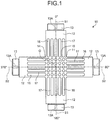
- FIG. 1 is a plan view of a cross-shaped test specimen according to the present embodiment.
- FIG. 2 is a partially enlarged view of the cross-shaped test specimen.
- a cross-shaped test specimen (biaxial load test specimen) 10 includes a main body 11 in which a first load axis S1 and a second load axis S2 intersecting at right angles; four arms 12 each extending from the main body 11 along the axial direction of the first load axis S1 or the second load axis S2; and a coupling unit 13 provided in each of the arms 12, in which the main body 11, the four arms 12, and the coupling unit 13 are integrated.
- the first load axis S1 and the second load axis S2 are orthogonal to each other.
- Each of the coupling units 13 includes a hole 13A to which a loading unit (not illustrated) configured to apply tensile or compressive loads (stresses) in the axial directions of the first load axis S1 and the second load axis S2 is coupled.
- the main body 11 is a plate-like object formed in an approximately rectangular shape, and functions as an evaluation area to evaluate a stress generated in the main body 11 when tensile or compressive loads are applied in the axial directions of the first load axis S1 and the second load axis S2.
- the main body 11 is configured to imitate, for example, a tube plate of a heat exchanger, and formed so as to have a larger thickness (for example, 30 mm to 150 mm) than a plate material for pressing.
- the main body 11 has a plurality of through-holes 14 arranged in a square matrix (in the example illustrated in FIG. 1 , arranged in five rows (5 ⁇ 5)).
- These through-holes 14 each imitate a hole to which a heat transfer tube of a heat exchanger (not illustrated) is connected, and are formed so as to be aligned along the axial directions of the first load axis S1 and the second load axis S2.
- the through-holes 14 are required to be arranged in at least two rows (2X2), and preferably arranged in three (3 ⁇ 3) or more rows, in which, more preferably, a center through-hole 14 is positioned at the intersection (the center) O of the first load axis S1 and the second load axis S2.
- the arms 12 have the function of transmitting a load applied in the axial direction of the first load axis S1 or the second load axis S2 to the main body 11, and are formed so as to have the same thickness as the main body 11.
- each of the arms 12 is provided with a plurality of slit grooves 16 extending along a direction in which the arm 12 extends, that is, along the axial direction of the first load axis S1 or the second load axis S2.
- the slit grooves 16 generate stress fields uniformly in the axial directions of load axes S1 and S2 in the main body 11.
- a tensile or compressive load applied to the main body 11 is placed on the ligament 15 except the through-holes 14, and therefore, the load is preferably smoothly transmitted to this ligament 15.
- each of the slit grooves 16 is positioned on an extension LA, that is, on the extension of a line L connecting the centers of the through-holes 14 aligned in the axial direction of the first load axis S1 or the second load axis S2. Accordingly, a load applied to the arm 12 acts on the ligament 15 of the main body 11 via a portion 17 between the slit grooves 16 and 16 adjoining each other, and thus the load can be smoothly transmitted to the ligament 15.
- each of the slit grooves 16 is formed so that a center line LC of the slit groove 16 coincides with the above-described extension LA.
- the portion 17 between the slit grooves 16 and 16 in the arm 12 and the ligament 15 in the main body 11 are positioned to be lined up straight, whereby a load can be smoothly transmitted to the ligament 15.
- each of the slit grooves 16 is formed to have a groove width DA equal to a diameter D of the through-holes 14.
- This configuration allows a width DB of the portion 17 between the slit grooves 16 and 16 to be equal to a ligament width DC between the through-holes 14 and 14.
- a load applied to the arm 12 can be more smoothly transmitted to the ligament 15.
- the groove width DA of the slit grooves 16 is much larger than the width of a conventional slit made by wire cutting, and accordingly, the slit groove can be machined, which results in a reduction in processing cost.
- the arms 12, as well as the main body 11, are formed to have a larger thickness than a plate material for pressing, and accordingly a greater effect in reducing processing cost is produced.
- the groove width DA of the slit grooves 16 is made larger, a larger partial-loss in the cross section of the arm 12 is caused, which could lead to a risk of a breakage of the arm 12.
- a breakage test is conducted not by applying a load to the cross-shaped test specimen 10 in a biaxial direction, but, a stress produced in the through-holes 14 when a load is applied is analyzed, and hence, even when the groove width DA of the slit grooves 16 is made equal to the diameter D of the through-holes 14, there is no problem in testing.
- a test for evaluating a stress produced in the through-hole 14 provided in the main body 11 is conducted in a state in which a load is applied to the cross-shaped test specimen 10 in the axial direction of the first load axis S1 or the second load axis S2.
- a test is conducted, for example, to see how a predetermined through-hole 14 (for example, a center through-hole 14) behaves when a stress is generated in each direction on a tube plate of a heat exchanger during the operation of a plant including the heat exchanger.
- FIG. 3 is a schematic diagram illustrating a test of pulling out a sealing plug provided in a through-hole of the cross-shaped test specimen.
- a center through-hole 14 provided at the center of the main body 11 of the cross-shaped test specimen 10 is provided with a sealing plug 70 for sealing the through-hole 14.
- a pulling rod 74 is connected to the upper side of the sealing plug 70.
- This pulling rod 74 penetrates a reaction-force base 73 disposed on the main body 11 (the ligament) of the cross-shaped test specimen 10, a center-hole jack 71, and a center-hole load cell 72, and is fixed with a nut 75.
- a displacement gauge 76 is provided on the lower side of the sealing plug 70, that is, on the opposite side of sealing plug 70 to the side on which the pulling rod 74 is provided.
- the pulling test is performed in such a manner that, in a state in which loads in the directions of the first load axis S1 and the second load axis S2 are applied to the cross-shaped test specimen 10, a pulling load is imposed on the sealing plug 70 by the center-hole jack 71. Then, a pulling load value at the time when the sealing plug 70 is displaced (starts to move) with the displacement gauge 76 is measured by the center-hole load cell 72.
- the load-carrying capacity of the sealing plug 70 provided in a predetermined through-hole 14 (for example, a center through-hole 14) can be determined, and furthermore, how the through-hole 14 behaves can be accurately understood.
- the pulling test may be performed not only by measuring a pulling load value by using the center-hole load cell 72, but also by determining whether the sealing plug 70 can be pulled out (displaced) or not pulled out (not displaced) in a state in which a fixed pulling load is applied.
- FIG. 4 is a schematic diagram illustrating a test of leakage from a pipe provided in a through-hole of the cross-shaped test specimen.
- a heat transfer tube (pipe) 80 is attached (fixed) to a center through-hole 14 provided at the center of the main body 11 of the cross-shaped test specimen 10.
- the heat transfer tube 80 is attached to the through-hole 14 of the main body 11 by a fixing means, such as tube expanding, soldering, or welding.
- the fixing means is the same as a means for attaching a heat transfer tube to a tube plate of a heat exchanger.
- the sealing plug 70 is attached to the inner surface of the heat transfer tube 80.
- a vessel 81 is fixed by a fixing means, such as welding, pressing, or adhesion, so as to cover one end of the heat transfer tube 80.
- the vessel 81 is connected to a pipe 82 communicating with an interior space.
- the pipe 82 is connected to a pressure pump 86, a valve 83, an air vent valve 84, and a pressure gauge 85.
- an observation means such as a video camera 89, is provided on the other end side of the heat transfer tube 80 across the sealing plug 70.
- a leakage test is performed in such a manner that, in a state in which loads are applied to the cross-shaped test specimen 10 in the directions of the first load axis S1 and the second load axis S2, the air vent valve 84 is closed, the vessel 81 is filled with a fluid (for example, water) 87, and the fluid 87 is pressurized with a pressure pump.
- a fluid for example, water
- the fluid 87 is pressurized with a pressure pump.
- the pressure of the fluid 87 reaches a predetermined pressure, then the valve 83 is closed to maintain the pressure of the fluid 87.
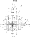
- FIG. 5 is a plan view of the biaxial load test apparatus suitable for the biaxial load test for the cross-shaped test specimen.
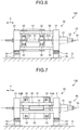
- FIG. 6 is a cross-sectional view taken along the line A-A in FIG. 5 .
- FIG. 7 is a cross-sectional view taken along the line B-B in FIG. 5 . As illustrated in FIG.
- a biaxial load test apparatus 100 includes: a first frame 30 having a first loading unit (first loading part) 20 configured to apply a tensile load to the cross-shaped test specimen 10 along an axial direction X of the first load axis S1; and a second frame 50 having a second loading unit (second loading part) 60 configured to apply a tensile load to the cross-shaped test specimen 10 along an axial direction Y of the second load axis S2.
- the first frame 30 includes: a pair of reaction force frames 31 and 31 spaced in the axial direction X of the first load axis S1; and four reaction force rods 32 configured to connect these reaction force frames 31 and 31.
- each of the reaction force frames 31 and 31 are installed via a corresponding one of first linear-motion bearings (first sliding units) 34 and 34 on a corresponding one of a pair of bases 33 and 33 disposed on an installation surface G.
- the first frame 30 is supported by the first linear-motion bearings 34 and 34 so as to be movable over a predetermined distance (for example, 0 mm to 20 mm) in the axial direction X of the first load axis S1.
- the first frame 30 is configured to be slidable on the bases 33 and 33 in the axial direction X of the first load axis S1.
- the first loading unit 20 includes a center-hole jack (first jack) 21 fixed to one of the reaction force frames 31, and a center-hole load cell 22.
- the center-hole jack 21 is coupled via a tension rod 23A to a coupling unit 13 ( FIG. 5 ) on one end side of the axial direction X of the first load axis S1 in the cross-shaped test specimen 10.
- the other one of the reaction force frames 31 is coupled via a tension rod 23B to another coupling unit 13 ( FIG. 5 ) on the other end side of the axial direction X of the first load axis S1 in the cross-shaped test specimen 10.
- the cross-shaped test specimen 10 is supported by the first frame 30 via the tension rods 23A and 23B.
- the center-hole jack 21 is a device configured to move the tension rod 23A forward and backward in the axial direction X of the first load axis S1, and is capable of applying a tensile load to the cross-shaped test specimen 10 in the axial direction X of the first load axis S1 via the tension rod 23A.
- the center-hole load cell 22 is configured to measure the magnitude of a tensile load applied by the center-hole jack 21.
- the second frame 50 includes: a pair of reaction force frames 51 and 51 spaced in the axial direction Y of the second load axis S2; and four reaction force rods 52 configured to connect these reaction force frames 51 and 51. As illustrated in FIG. 7 , these reaction force rods 52 are positioned so as not to interfere with the reaction force rods 32 of the first frame 30.
- the reaction force frames 51 and 51 are installed, via second linear-motion bearings (second sliding units) 54 and 54, on a pair of bases 53 and 53 disposed on the installation surface G.
- the second frame 50 is supported by the second linear-motion bearings 54 and 54 so as to be movable over a predetermined distance (for example, 0 mm to 20 mm) in the axial direction Y of the second load axis S2.
- a predetermined distance for example, 0 mm to 20 mm
- the second frame 50 is configured to be slidable on the bases 53 and 53 in the axial direction Y of the second load axis S2.
- the second loading unit 60 includes a center-hole jack (second jack) 61 fixed to one of the reaction force frames 51, and a center-hole load cell 62.
- the center-hole jack 61 is coupled via a tension rod 63A to a coupling unit 13 ( FIG. 5 ) on one end side of the axial direction Y of the second load axis S2 in the cross-shaped test specimen 10.
- the other one of the reaction force frames 51 is coupled via a tension rod 63B to a coupling unit 13 ( FIG. 5 ) on the other end side of the axial direction Y of the second load axis S2 in the cross-shaped test specimen 10.
- the cross-shaped test specimen 10 is supported also by the second frame 50 via the tension rods 63A and 63B.
- the first frame 30 and the second frame 50 are connected to each other via the cross-shaped test specimen 10.
- the center-hole jack 61 is a device configured to move the tension rod 63A forward and backward in the axial direction Y of the second load axis S2, and is capable of applying a tensile load to the cross-shaped test specimen 10 via the tension rod 63A in the axial direction Y of the second load axis S2.
- the center-hole load cell 62 is configured to measure the magnitude of a tensile load applied by the center-hole jack 61.
- FIG. 8 and FIG. 9 are schematic diagrams illustrating the operation of the biaxial load test apparatus.
- the cross-shaped test specimen 10 is connected to the first frame 30 and the second frame 50 via the respective tension rods.
- the center-hole jack 21 applies a tensile load to the cross-shaped test specimen 10 in an axial direction X1 of the first load axis S1.
- the cross-shaped test specimen 10 is deformed and tends to stretch in the axial direction X1 due to the tensile load, but, since the cross-shaped test specimen 10 is connected with the second frame 50 via the tension rods 63A and 63B ( FIG. 5 ), the cross-shaped test specimen 10 is restrained from stretching in the axial direction X1. Accordingly, a reaction force of the tensile load applied to the cross-shaped test specimen 10 acts in an axial direction X2, and the first frame 30 is moved in the axial direction X2 by the first linear-motion bearings 34 and 34, whereby the cross-shaped test specimen 10 stretches in both the axial directions X1 and X2.
- the center-hole jack 61 applies a tensile load to the cross-shaped test specimen 10 in an axial direction Y1 of the second load axis S2
- the cross-shaped test specimen 10 is deformed and tends to stretch in the axial direction Y1 due to the tensile load, but, since the cross-shaped test specimen 10 is connected with the first frame 30 via the tension rods 23A and 23B ( FIG. 5 ), the cross-shaped test specimen 10 is restrained from stretching in the axial direction Y1.
- a reaction force of the tensile load applied to the cross-shaped test specimen 10 acts in an axial direction Y2, and the second frame 50 is moved in the axial direction Y2 by the second linear-motion bearings 54 and 54, whereby the cross-shaped test specimen 10 stretches in both the axial directions Y1 and Y2.
- the biaxial load test apparatus 100 includes: the first frame 30 having the first loading unit 20 configured to apply a tensile load to the cross-shaped test specimen 10 along the axial direction X of the first load axis S1; the second frame 50 having the second loading unit 60 configured to apply a tensile load to the cross-shaped test specimen 10 along the axial direction Y of the second load axis S2; the first linear-motion bearing 34 configured to slide the first frame 30 in the axial direction X of the first load axis S1 with respect to the installation surface G; and the second linear-motion bearing 54 configured to slide the second frame 50 in the axial direction Y of the second load axis S2 with respect to the installation surface G, and thus, reaction forces of loads applied to the cross-shaped test specimen 10 in the axial directions X and Y respectively act on the first frame 30 and the second frame 50, so that the first frame 30 and the second frame 50 are moved by the first linear-motion bearing 34 and the second linear-motion bearing 54, respectively
- the first frame 30 and the second frame 50 move in respective directions opposite to the directions in which the loads are applied, and therefore, even when a tensile load is applied to the cross-shaped test specimen 10, the center O of the cross-shaped test specimen 10 is not shifted.
- This brings about an effect that, for example, observation can be easily performed on the occasion of a load-carrying capacity measurement of the plug in a through-hole 14 positioned at the center O of the cross-shaped test specimen 10 or a fluid leakage test.
- the first loading unit 20 and the second loading unit 60 are provided, and hence by operating the first loading unit 20 and the second loading unit 60 independently, loads of different magnitudes can be applied in the respective axial directions X and Y.
- FIG. 10 is a schematic diagram of the biaxial load test apparatus according to the embodiment.
- the biaxial load test apparatus 150 includes: a frame 110 installed on an installation surface (not-illustrated); the first loading unit 20 configured to apply a tensile or compressive load to the cross-shaped test specimen 10 along the axial direction X of the first load axis S1; and the second loading unit 60 configured to apply a tensile or compressive load to the cross-shaped test specimen 10 along the axial direction Y of the second load axis S2.
- the first loading unit 20 and the second loading unit 60 are the same as those of the above-described configuration, and therefore, descriptions thereof will be omitted.
- FIG. 10 only the rods 23A and 63A are illustrated, whereas illustrations of rods corresponding to the rods 23B and 63B ( FIG. 5 ) are omitted.
- the biaxial load test apparatus 150 further includes: first linear-motion bearings (first sliding units) 120 and 121 configured to slide the first loading unit 20 and the cross-shaped test specimen 10 in the axial direction Y of the second load axis S2 with respect to the frame 110; and second linear-motion bearings (second sliding units) 130 and 131 configured to slide the second loading unit 60 and the cross-shaped test specimen 10 in the axial direction X of the first load axis S1 with respect to the frame 110.
- the first linear-motion bearing 120 slidably supports the jack 21 of the first loading unit 20 with respect to the frame 110
- the first linear-motion bearing 121 slidably supports the coupling unit 13 (or the rod 23B not illustrated) of the cross-shaped test specimen 10 with respect to the frame 110.
- the second linear-motion bearing 130 slidably supports the jack 61 of the second loading unit 60 with respect to the frame 110
- the second linear-motion bearing 131 slidably supports the coupling unit 13 (or the rod 63B not illustrated) of the cross-shaped test specimen 10 with respect to the frame 110.
- the cross-shaped test specimen 10 when the jack 21 applies a load to the cross-shaped test specimen 10 in the axial direction X of the first load axis S1, the cross-shaped test specimen 10 is deformed to be stretched or shortened in the axial direction X due to the load.
- the second loading unit 60 connected to the cross-shaped test specimen 10 is moved together with the cross-shaped test specimen 10 in the axial direction X by the second linear-motion bearings 130 and 131.
- the jack 61 applies a load to the cross-shaped test specimen 10 in the axial direction Y of the second load axis S2
- the cross-shaped test specimen 10 is deformed to be stretched or shortened in the axial direction Y due to the load.
- the first loading unit 20 connected to the cross-shaped test specimen 10 is moved together with the cross-shaped test specimen 10 in the axial direction Y by the first linear-motion bearings 120 and 121.
- the biaxial load test apparatus 150 includes: the frame 110 installed on the installation surface (not-illustrated); the first loading unit 20 configured to apply a tensile or compressive load to the cross-shaped test specimen 10 along the axial direction X of the first load axis S1; the second loading unit 60 configured to apply a tensile or compressive load to the arms 12 of the cross-shaped test specimen 10 along the axial direction Y of the second load axis S2; and the first linear-motion bearings 120 and 121 (first sliding units) configured to slide the first loading unit 20 and the cross-shaped test specimen 10 in the axial direction Y of the second load axis S2 with respect to the frame 110, in which the first loading unit 20 and the second loading unit 60 move together with the cross-shaped test specimen 10 in the axial direction X or the axial direction Y with respect to the frame 110.
- This configuration prevents a combined biaxial load from being applied to the cross-shaped test specimen 10, and thus allows a pure load to be applied along
- the first loading unit 20 and the second loading unit 60 are provided, and hence by operating the first loading unit 20 and the second loading unit 60 independently, loads of different magnitudes can be applied in the respective axial directions X and Y.
- the biaxial load test apparatus 100 is configured so as to include: the first loading unit 20 configured to apply a tensile load to the cross-shaped test specimen 10 in the axial direction X of the first load axis S1; and the second loading unit 60 configured to apply a tensile load to the cross-shaped test specimen 10 in the axial direction Y of the second load axis S2, but, the biaxial load test apparatus may include a first loading unit and a second loading unit configured to apply not only a tensile load but also a compressive load in the respective axial directions X and Y.
Landscapes
- Physics & Mathematics (AREA)
- Health & Medical Sciences (AREA)
- Life Sciences & Earth Sciences (AREA)
- Chemical & Material Sciences (AREA)
- Analytical Chemistry (AREA)
- Biochemistry (AREA)
- General Health & Medical Sciences (AREA)
- General Physics & Mathematics (AREA)
- Immunology (AREA)
- Pathology (AREA)
- Investigating Strength Of Materials By Application Of Mechanical Stress (AREA)
- Examining Or Testing Airtightness (AREA)
Abstract
Description
- The present invention relates to a biaxial load test specimen to which loads are applied along the axial directions of two load axes orthogonal to each other, a biaxial load test apparatus, and a biaxial load test method.
- There is generally known a biaxial tensile test (biaxial load test) method for directly measuring stress-strain characteristics of a material under biaxial stress in pressed-component design or die design. In such a biaxial tensile test method, use is made of a cross-shaped test specimen (a biaxial load test specimen) that includes main body in which two load axes are orthogonal to each other, and four arms extending from the main body along the respective axial directions of the load axes. Each of the four arms of this conventional cross-shaped test specimen is provided with a slit in order to generate stress fields uniformly in the axial directions of the load axes and thereby cause the main body to be in a desired biaxial stress state (for example, see Patent Literature 1). A larger slit-width causes a larger partial-loss in the cross section of the arm, whereby a slit portion breaks first, so that a sufficient load cannot be applied to an evaluation unit. Therefore, the slit-width needs to be smaller as much as possible and hence the slit is generally processed by expensive wire cutting.
- Patent Literature 1: Japanese Patent Application Laid-open No.
2014-228290 - In recent years, there has been searched for an analysis of stresses generated in a plurality of through-holes formed in a perforated plate such as a tube plate of a heat exchanger by using the above-described biaxial tensile test (biaxial load test) method. Also in the configuration in which a plurality of through-holes is provided in the main body, each of four arms needs to be provided with a slit in order to generate stress fields uniformly in the axial directions of the load axes. However, in the configuration in which a plurality of through-holes is provided in the main body, a tensile or compressive load (stress) applied to the main body is placed on a ligament except the through-holes, and hence, the load is preferably transmitted to this ligament smoothly.
- The present invention has been made in view of the above, and an object of the present invention is to provide a biaxial load test specimen capable of transmitting a load smoothly to the ligament of the main body, except the through-holes, a biaxial load test apparatus, and a biaxial load test method.
- To solve the problem described above and achieve the object, a biaxial load test specimen according to the present invention includes a main body having a plurality of through-holes aligned along axial directions of two load axes orthogonal to each other; and four arms extending from the main body in the respective axial directions of the load axes. Each of the arms has a plurality of slit grooves extending, on respective extensions of the through-holes aligned in the axial directions, along the respective axial directions.
- With this configuration, each of the arms has a plurality of slit grooves extending, on the respective extensions of the through-holes aligned in axial directions, along the respective axial directions, and thus, a load applied to each of the arms acts on the ligament of the main body, except the through-holes, through between the slit grooves. Therefore, a load can be smoothly transmitted to the ligament.
- In this configuration, it is preferable that a center line of each slit groove is positioned on a corresponding extension of the through-holes. With this configuration, the center line of the arm between the slit grooves coincides with the center line of the ligament of the main body, except the through-holes, and accordingly, a load can be smoothly transmitted to the ligament.
- Furthermore, it is preferable that the slit grooves have a groove width equal to a diameter of the through-holes. With this configuration, the slit has a larger width than a wire-cut slit, and therefore the slit groove can be machined, resulting in a reduction in processing cost.
- Furthermore, the present invention is a biaxial load test apparatus configured to perform a load test for a test specimen by applying a load to the test specimen along each of axial directions of a first load axis and a second load axis which are orthogonal to each other. The apparatus includes a first frame including a first loading unit configured to apply a tensile or compressive load to the test specimen along the axial direction of the first load axis; a second frame including a second loading unit configured to apply a tensile or compressive load to the test specimen along the axial direction of the second load axis; a first sliding unit configured to slide the first frame in the axial direction of the first load axis with respect to an installation surface; and a second sliding unit configured to slide the second frame in the axial direction of the second load axis with respect to the installation surface.
- With this configuration, reaction forces of loads applied to the test specimen in the axial directions respectively act on the first frame and the second frame, so that the first frame and the second frame are moved by the first sliding unit and the second sliding unit, respectively, in respective opposite directions to the directions in which the loads are applied. Thus, a combined biaxial load is prevented from being applied to the arms of the test specimen, so that a pure load can be applied to each of the arms along a corresponding one of the axial directions.
- The present invention is a biaxial load test apparatus configured to perform a load test for a test specimen by applying a load to the test specimen along each of axial directions of a first load axis and a second load axis which are orthogonal to each other. The apparatus includes a frame to be installed on an installation surface; a first loading unit configured to apply a tensile or compressive load to the test specimen along the axial direction of the first load axis; a second loading unit configured to apply a tensile or compressive load to the test specimen along the axial direction of the second load axis; a first sliding unit configured to slide the first loading unit and the test specimen in the axial direction of the second load axis with respect to the frame; and a second sliding unit configured to slide the second loading unit and the test specimen in the axial direction of the first load axis with respect to the frame.
- Furthermore, it is preferable that the test specimen includes a main body having a plurality of through-holes aligned along axial directions of two load axes orthogonal to each other, and four arms extending from the main body in the respective axial directions of the load axes, wherein each of the arms has a plurality of slit grooves extending, on respective extensions of the through-holes aligned in the axial directions, along the respective axial directions.
- Furthermore, a biaxial load test method according to the present invention includes the steps of: providing at least one of the through-holes formed in the main body of the biaxial load test specimen described above with a sealing plug configured to seal the at least one of the through-holes; applying a load to the arms of the biaxial load test specimen along the respective axial directions of the load axes; and in a state where the load is applied, applying a pulling load to pull out the sealing plug from the through-hole.
- This configuration allows an accurate understanding of behaviors such as deformation of the through-holes formed in the main body in a state in which loads are applied to the respective arms of the biaxial load test specimen along the respective axial directions of the load axes.
- Furthermore, a biaxial load test method according to the present invention includes the steps of: fixing a pipe to at least one of the through-holes formed in the main body of the biaxial load test specimen described above; applying a load to the arms of the biaxial load test specimen along the respective axial directions of the load axes; and in a state where the load is applied, filling one end side of the pipe with a fluid pressurized to a predetermined pressure.
- This configuration allows an accurate understanding of behaviors such as deformation of the through-holes formed in the main body in a state in which loads are applied to the respective arms of the biaxial load test specimen along the respective axial directions of the load axes.
- According to the present invention, each of the arms has a plurality of slit grooves extending, on the respective extensions of the through-holes aligned in axial directions, along the respective axial directions, and thus, loads applied to the respective arms act on the ligament of the main body, except the through-holes, through between the slit grooves. Thus, loads can be smoothly transmitted to the ligament.
-
-
FIG. 1 is a plan view of a cross-shaped test specimen according to an embodiment. -
FIG. 2 is a partially enlarged view of the cross-shaped test specimen. -
FIG. 3 is a schematic diagram illustrating a test of pulling out a sealing plug provided in a through-hole of the cross-shaped test specimen. -
FIG. 4 is a schematic diagram illustrating a test of leakage from a pipe provided in a through-hole of the cross-shaped test specimen. -
FIG. 5 is a plan view of a biaxial load test apparatus suitable for a biaxial load test for the cross-shaped test specimen. -
FIG. 6 is a cross-sectional view taken along a line A-A inFIG. 5 . -
FIG. 7 is a cross-sectional view taken along a line B-B inFIG. 5 . -
FIG. 8 is a schematic diagram illustrating an operation of a biaxial load test apparatus. -
FIG. 9 is a schematic diagram illustrating the operation of the biaxial load test apparatus. -
FIG. 10 is a schematic diagram of a biaxial load test apparatus according to another embodiment. - Hereinafter, embodiments of the present invention will be described in detail with reference to the drawings. Note that the present invention is not limited by the embodiments. In addition, constituent elements in the following embodiments include those that can be easily replaced by those skilled in the art or substantially the same. Furthermore, the constituent elements described below can be appropriately used in combination.
-
FIG. 1 is a plan view of a cross-shaped test specimen according to the present embodiment.FIG. 2 is a partially enlarged view of the cross-shaped test specimen. As illustrated inFIG. 1 , a cross-shaped test specimen (biaxial load test specimen) 10 includes amain body 11 in which a first load axis S1 and a second load axis S2 intersecting at right angles; fourarms 12 each extending from themain body 11 along the axial direction of the first load axis S1 or the second load axis S2; and acoupling unit 13 provided in each of thearms 12, in which themain body 11, the fourarms 12, and thecoupling unit 13 are integrated. The first load axis S1 and the second load axis S2 are orthogonal to each other. The fourarms 12 extend in different directions shifted by every 90 degrees around themain body 11. Each of thecoupling units 13 includes ahole 13A to which a loading unit (not illustrated) configured to apply tensile or compressive loads (stresses) in the axial directions of the first load axis S1 and the second load axis S2 is coupled. - The
main body 11 is a plate-like object formed in an approximately rectangular shape, and functions as an evaluation area to evaluate a stress generated in themain body 11 when tensile or compressive loads are applied in the axial directions of the first load axis S1 and the second load axis S2. In the present embodiment, themain body 11 is configured to imitate, for example, a tube plate of a heat exchanger, and formed so as to have a larger thickness (for example, 30 mm to 150 mm) than a plate material for pressing. Themain body 11 has a plurality of through-holes 14 arranged in a square matrix (in the example illustrated inFIG. 1 , arranged in five rows (5×5)). These through-holes 14 each imitate a hole to which a heat transfer tube of a heat exchanger (not illustrated) is connected, and are formed so as to be aligned along the axial directions of the first load axis S1 and the second load axis S2. The through-holes 14 are required to be arranged in at least two rows (2X2), and preferably arranged in three (3×3) or more rows, in which, more preferably, a center through-hole 14 is positioned at the intersection (the center) O of the first load axis S1 and the second load axis S2. - The
arms 12 have the function of transmitting a load applied in the axial direction of the first load axis S1 or the second load axis S2 to themain body 11, and are formed so as to have the same thickness as themain body 11. As illustrated inFIG. 1 , each of thearms 12 is provided with a plurality ofslit grooves 16 extending along a direction in which thearm 12 extends, that is, along the axial direction of the first load axis S1 or the second load axis S2. Theslit grooves 16 generate stress fields uniformly in the axial directions of load axes S1 and S2 in themain body 11. Here, in a configuration in which a plurality of through-holes 14 are formed in themain body 11, as indicated by an arrow F inFIG. 2 , a tensile or compressive load applied to themain body 11 is placed on theligament 15 except the through-holes 14, and therefore, the load is preferably smoothly transmitted to thisligament 15. - In the present embodiment, as illustrated in
FIG. 2 , each of theslit grooves 16 is positioned on an extension LA, that is, on the extension of a line L connecting the centers of the through-holes 14 aligned in the axial direction of the first load axis S1 or the second load axis S2. Accordingly, a load applied to thearm 12 acts on theligament 15 of themain body 11 via aportion 17 between theslit grooves ligament 15. - In the present embodiment, each of the
slit grooves 16 is formed so that a center line LC of theslit groove 16 coincides with the above-described extension LA. Thus, theportion 17 between theslit grooves arm 12 and theligament 15 in themain body 11 are positioned to be lined up straight, whereby a load can be smoothly transmitted to theligament 15. - In the present embodiment, as illustrated in
FIG. 2 , each of theslit grooves 16 is formed to have a groove width DA equal to a diameter D of the through-holes 14. This configuration allows a width DB of theportion 17 between theslit grooves holes arm 12 can be more smoothly transmitted to theligament 15. Furthermore, the groove width DA of theslit grooves 16 is much larger than the width of a conventional slit made by wire cutting, and accordingly, the slit groove can be machined, which results in a reduction in processing cost. In particular, in the present embodiment, thearms 12, as well as themain body 11, are formed to have a larger thickness than a plate material for pressing, and accordingly a greater effect in reducing processing cost is produced. Here, in the case where the groove width DA of theslit grooves 16 is made larger, a larger partial-loss in the cross section of thearm 12 is caused, which could lead to a risk of a breakage of thearm 12. In the present embodiment, a breakage test is conducted not by applying a load to thecross-shaped test specimen 10 in a biaxial direction, but, a stress produced in the through-holes 14 when a load is applied is analyzed, and hence, even when the groove width DA of theslit grooves 16 is made equal to the diameter D of the through-holes 14, there is no problem in testing. - Next, a biaxial load test using the
cross-shaped test specimen 10 will be described. In the present embodiment, a test for evaluating a stress produced in the through-hole 14 provided in themain body 11 is conducted in a state in which a load is applied to thecross-shaped test specimen 10 in the axial direction of the first load axis S1 or the second load axis S2. As described above, since themain body 11 imitates a tube plate of a heat exchanger, a test is conducted, for example, to see how a predetermined through-hole 14 (for example, a center through-hole 14) behaves when a stress is generated in each direction on a tube plate of a heat exchanger during the operation of a plant including the heat exchanger. -
FIG. 3 is a schematic diagram illustrating a test of pulling out a sealing plug provided in a through-hole of the cross-shaped test specimen. As illustrated inFIG. 3 , a center through-hole 14 provided at the center of themain body 11 of thecross-shaped test specimen 10 is provided with a sealingplug 70 for sealing the through-hole 14. Subsequently, a pullingrod 74 is connected to the upper side of the sealingplug 70. This pullingrod 74 penetrates a reaction-force base 73 disposed on the main body 11 (the ligament) of thecross-shaped test specimen 10, a center-hole jack 71, and a center-hole load cell 72, and is fixed with anut 75. Adisplacement gauge 76 is provided on the lower side of the sealingplug 70, that is, on the opposite side of sealingplug 70 to the side on which the pullingrod 74 is provided. - The pulling test is performed in such a manner that, in a state in which loads in the directions of the first load axis S1 and the second load axis S2 are applied to the
cross-shaped test specimen 10, a pulling load is imposed on the sealingplug 70 by the center-hole jack 71. Then, a pulling load value at the time when the sealingplug 70 is displaced (starts to move) with thedisplacement gauge 76 is measured by the center-hole load cell 72. With this configuration, for example, when a stress is generated in each direction on a tube plate of a heat exchanger, the load-carrying capacity of the sealingplug 70 provided in a predetermined through-hole 14 (for example, a center through-hole 14) can be determined, and furthermore, how the through-hole 14 behaves can be accurately understood. The pulling test may be performed not only by measuring a pulling load value by using the center-hole load cell 72, but also by determining whether the sealingplug 70 can be pulled out (displaced) or not pulled out (not displaced) in a state in which a fixed pulling load is applied. -
FIG. 4 is a schematic diagram illustrating a test of leakage from a pipe provided in a through-hole of the cross-shaped test specimen. As illustrated inFIG. 4 , a heat transfer tube (pipe) 80 is attached (fixed) to a center through-hole 14 provided at the center of themain body 11 of thecross-shaped test specimen 10. Theheat transfer tube 80 is attached to the through-hole 14 of themain body 11 by a fixing means, such as tube expanding, soldering, or welding. The fixing means is the same as a means for attaching a heat transfer tube to a tube plate of a heat exchanger. Subsequently, the sealingplug 70 is attached to the inner surface of theheat transfer tube 80. - On the upper side of the main body 11 (the ligament 15), a
vessel 81 is fixed by a fixing means, such as welding, pressing, or adhesion, so as to cover one end of theheat transfer tube 80. Thevessel 81 is connected to apipe 82 communicating with an interior space. Thepipe 82 is connected to apressure pump 86, avalve 83, anair vent valve 84, and apressure gauge 85. Below themain body 11, an observation means, such as avideo camera 89, is provided on the other end side of theheat transfer tube 80 across the sealingplug 70. - A leakage test is performed in such a manner that, in a state in which loads are applied to the
cross-shaped test specimen 10 in the directions of the first load axis S1 and the second load axis S2, theair vent valve 84 is closed, thevessel 81 is filled with a fluid (for example, water) 87, and the fluid 87 is pressurized with a pressure pump. Thus, one end side of theheat transfer tube 80, the end being positioned inside thevessel 81, is filled with thepressurized fluid 87. When the pressure of the fluid 87 reaches a predetermined pressure, then thevalve 83 is closed to maintain the pressure of the fluid 87. On the other end side of theheat transfer tube 80 across the sealingplug 70, whether aleakage 88 of thepressurized fluid 87 has been caused is observed based on images captured by thevideo camera 89. This configuration allows, for example, an accurate understanding of how theheat transfer tube 80 provided in a predetermined through-hole 14 (for example, the center through-hole 14) behaves when a stress is generated in each direction on a tube plate of a heat exchanger. - In the case where tensile or compressive loads are applied to the
cross-shaped test specimen 10 in the axial directions of the first load axis S1 and the second load axis S2, when the loads in the axial directions are combined and applied to thearms 12 of thecross-shaped test specimen 10, a test cannot be accurately conducted. Therefore, there is assumed a configuration in which each of thearms 12 of thecross-shaped test specimen 10 is provided with a loading unit (not illustrated) configured to apply a tensile or compressive load in an axial direction. However, this configuration causes the problem that the apparatus has a more complicated structure. Therefore, a technique of applying loads in four directions by using a single loading unit has been proposed (for example, Japanese Patent Application Laid-open No.58-173450 arms 12 of thecross-shaped test specimen 10 as well as capable of applying loads independently to the axial directions. - Next, a biaxial load test apparatus configured to conduct a biaxial load test by using the above-described
cross-shaped test specimen 10 will be described.FIG. 5 is a plan view of the biaxial load test apparatus suitable for the biaxial load test for the cross-shaped test specimen.FIG. 6 is a cross-sectional view taken along the line A-A inFIG. 5 .FIG. 7 is a cross-sectional view taken along the line B-B inFIG. 5 . As illustrated inFIG. 5 , a biaxialload test apparatus 100 includes: afirst frame 30 having a first loading unit (first loading part) 20 configured to apply a tensile load to thecross-shaped test specimen 10 along an axial direction X of the first load axis S1; and asecond frame 50 having a second loading unit (second loading part) 60 configured to apply a tensile load to thecross-shaped test specimen 10 along an axial direction Y of the second load axis S2. - As illustrated in
FIG. 5 andFIG. 6 , thefirst frame 30 includes: a pair of reaction force frames 31 and 31 spaced in the axial direction X of the first load axis S1; and fourreaction force rods 32 configured to connect these reaction force frames 31 and 31. As illustrated inFIG. 6 , each of the reaction force frames 31 and 31 are installed via a corresponding one of first linear-motion bearings (first sliding units) 34 and 34 on a corresponding one of a pair of bases 33 and 33 disposed on an installation surface G. Thefirst frame 30 is supported by the first linear-motion bearings first frame 30 is configured to be slidable on the bases 33 and 33 in the axial direction X of the first load axis S1. - The
first loading unit 20 includes a center-hole jack (first jack) 21 fixed to one of the reaction force frames 31, and a center-hole load cell 22. The center-hole jack 21 is coupled via atension rod 23A to a coupling unit 13 (FIG. 5 ) on one end side of the axial direction X of the first load axis S1 in thecross-shaped test specimen 10. The other one of the reaction force frames 31 is coupled via atension rod 23B to another coupling unit 13 (FIG. 5 ) on the other end side of the axial direction X of the first load axis S1 in thecross-shaped test specimen 10. Thus, thecross-shaped test specimen 10 is supported by thefirst frame 30 via thetension rods - The center-
hole jack 21 is a device configured to move thetension rod 23A forward and backward in the axial direction X of the first load axis S1, and is capable of applying a tensile load to thecross-shaped test specimen 10 in the axial direction X of the first load axis S1 via thetension rod 23A. The center-hole load cell 22 is configured to measure the magnitude of a tensile load applied by the center-hole jack 21. - On the other hand, as illustrated in
FIG. 5 andFIG. 7 , thesecond frame 50 includes: a pair of reaction force frames 51 and 51 spaced in the axial direction Y of the second load axis S2; and fourreaction force rods 52 configured to connect these reaction force frames 51 and 51. As illustrated inFIG. 7 , thesereaction force rods 52 are positioned so as not to interfere with thereaction force rods 32 of thefirst frame 30. The reaction force frames 51 and 51 are installed, via second linear-motion bearings (second sliding units) 54 and 54, on a pair ofbases second frame 50 is supported by the second linear-motion bearings second frame 50 is configured to be slidable on thebases - The
second loading unit 60 includes a center-hole jack (second jack) 61 fixed to one of the reaction force frames 51, and a center-hole load cell 62. The center-hole jack 61 is coupled via atension rod 63A to a coupling unit 13 (FIG. 5 ) on one end side of the axial direction Y of the second load axis S2 in thecross-shaped test specimen 10. The other one of the reaction force frames 51 is coupled via atension rod 63B to a coupling unit 13 (FIG. 5 ) on the other end side of the axial direction Y of the second load axis S2 in thecross-shaped test specimen 10. Thus, thecross-shaped test specimen 10 is supported also by thesecond frame 50 via thetension rods first frame 30 and thesecond frame 50 are connected to each other via thecross-shaped test specimen 10. - The center-
hole jack 61 is a device configured to move thetension rod 63A forward and backward in the axial direction Y of the second load axis S2, and is capable of applying a tensile load to thecross-shaped test specimen 10 via thetension rod 63A in the axial direction Y of the second load axis S2. The center-hole load cell 62 is configured to measure the magnitude of a tensile load applied by the center-hole jack 61. - Next, an operation of the biaxial
load test apparatus 100 will be described.FIG. 8 and FIG. 9 are schematic diagrams illustrating the operation of the biaxial load test apparatus. As illustrated inFIG. 8 , thecross-shaped test specimen 10 is connected to thefirst frame 30 and thesecond frame 50 via the respective tension rods. As illustrated inFIG. 9 , with this state kept, the center-hole jack 21 applies a tensile load to thecross-shaped test specimen 10 in an axial direction X1 of the first load axis S1. - In this case, the
cross-shaped test specimen 10 is deformed and tends to stretch in the axial direction X1 due to the tensile load, but, since thecross-shaped test specimen 10 is connected with thesecond frame 50 via thetension rods FIG. 5 ), thecross-shaped test specimen 10 is restrained from stretching in the axial direction X1. Accordingly, a reaction force of the tensile load applied to thecross-shaped test specimen 10 acts in an axial direction X2, and thefirst frame 30 is moved in the axial direction X2 by the first linear-motion bearings cross-shaped test specimen 10 stretches in both the axial directions X1 and X2. - Similarly, when the center-
hole jack 61 applies a tensile load to thecross-shaped test specimen 10 in an axial direction Y1 of the second load axis S2, thecross-shaped test specimen 10 is deformed and tends to stretch in the axial direction Y1 due to the tensile load, but, since thecross-shaped test specimen 10 is connected with thefirst frame 30 via thetension rods FIG. 5 ), thecross-shaped test specimen 10 is restrained from stretching in the axial direction Y1. Accordingly, a reaction force of the tensile load applied to thecross-shaped test specimen 10 acts in an axial direction Y2, and thesecond frame 50 is moved in the axial direction Y2 by the second linear-motion bearings cross-shaped test specimen 10 stretches in both the axial directions Y1 and Y2. - As described above, the biaxial
load test apparatus 100 according to the present embodiment includes: thefirst frame 30 having thefirst loading unit 20 configured to apply a tensile load to thecross-shaped test specimen 10 along the axial direction X of the first load axis S1; thesecond frame 50 having thesecond loading unit 60 configured to apply a tensile load to thecross-shaped test specimen 10 along the axial direction Y of the second load axis S2; the first linear-motion bearing 34 configured to slide thefirst frame 30 in the axial direction X of the first load axis S1 with respect to the installation surface G; and the second linear-motion bearing 54 configured to slide thesecond frame 50 in the axial direction Y of the second load axis S2 with respect to the installation surface G, and thus, reaction forces of loads applied to thecross-shaped test specimen 10 in the axial directions X and Y respectively act on thefirst frame 30 and thesecond frame 50, so that thefirst frame 30 and thesecond frame 50 are moved by the first linear-motion bearing 34 and the second linear-motion bearing 54, respectively, in respective directions opposite to the directions in which the loads are applied. Thus, a combined biaxial load is prevented from being applied to thearms 12 of thecross-shaped test specimen 10, and a pure load can be applied along each of the axial directions X and Y. - In the present embodiment, the
first frame 30 and thesecond frame 50 move in respective directions opposite to the directions in which the loads are applied, and therefore, even when a tensile load is applied to thecross-shaped test specimen 10, the center O of thecross-shaped test specimen 10 is not shifted. This brings about an effect that, for example, observation can be easily performed on the occasion of a load-carrying capacity measurement of the plug in a through-hole 14 positioned at the center O of thecross-shaped test specimen 10 or a fluid leakage test. - In the present embodiment, the
first loading unit 20 and thesecond loading unit 60 are provided, and hence by operating thefirst loading unit 20 and thesecond loading unit 60 independently, loads of different magnitudes can be applied in the respective axial directions X and Y. - Next, a biaxial
load test apparatus 150 according to another embodiment will be described.FIG. 10 is a schematic diagram of the biaxial load test apparatus according to the embodiment. As illustrated inFIG. 10 , the biaxialload test apparatus 150 includes: aframe 110 installed on an installation surface (not-illustrated); thefirst loading unit 20 configured to apply a tensile or compressive load to thecross-shaped test specimen 10 along the axial direction X of the first load axis S1; and thesecond loading unit 60 configured to apply a tensile or compressive load to thecross-shaped test specimen 10 along the axial direction Y of the second load axis S2. Thefirst loading unit 20 and thesecond loading unit 60 are the same as those of the above-described configuration, and therefore, descriptions thereof will be omitted. Furthermore, inFIG. 10 , only therods rods FIG. 5 ) are omitted. - The biaxial
load test apparatus 150 further includes: first linear-motion bearings (first sliding units) 120 and 121 configured to slide thefirst loading unit 20 and thecross-shaped test specimen 10 in the axial direction Y of the second load axis S2 with respect to theframe 110; and second linear-motion bearings (second sliding units) 130 and 131 configured to slide thesecond loading unit 60 and thecross-shaped test specimen 10 in the axial direction X of the first load axis S1 with respect to theframe 110. The first linear-motion bearing 120 slidably supports thejack 21 of thefirst loading unit 20 with respect to theframe 110, whereas the first linear-motion bearing 121 slidably supports the coupling unit 13 (or therod 23B not illustrated) of thecross-shaped test specimen 10 with respect to theframe 110. - Similarly, the second linear-
motion bearing 130 slidably supports thejack 61 of thesecond loading unit 60 with respect to theframe 110, whereas the second linear-motion bearing 131 slidably supports the coupling unit 13 (or therod 63B not illustrated) of thecross-shaped test specimen 10 with respect to theframe 110. - With this configuration, when the
jack 21 applies a load to thecross-shaped test specimen 10 in the axial direction X of the first load axis S1, thecross-shaped test specimen 10 is deformed to be stretched or shortened in the axial direction X due to the load. In this case, with the deformation of thecross-shaped test specimen 10 in the axial direction X, thesecond loading unit 60 connected to thecross-shaped test specimen 10 is moved together with thecross-shaped test specimen 10 in the axial direction X by the second linear-motion bearings - Similarly, when the
jack 61 applies a load to thecross-shaped test specimen 10 in the axial direction Y of the second load axis S2, thecross-shaped test specimen 10 is deformed to be stretched or shortened in the axial direction Y due to the load. In this case, with the deformation of thecross-shaped test specimen 10 in the axial direction Y, thefirst loading unit 20 connected to thecross-shaped test specimen 10 is moved together with thecross-shaped test specimen 10 in the axial direction Y by the first linear-motion bearings - As described above, the biaxial
load test apparatus 150 according to the present embodiment includes: theframe 110 installed on the installation surface (not-illustrated); thefirst loading unit 20 configured to apply a tensile or compressive load to thecross-shaped test specimen 10 along the axial direction X of the first load axis S1; thesecond loading unit 60 configured to apply a tensile or compressive load to thearms 12 of thecross-shaped test specimen 10 along the axial direction Y of the second load axis S2; and the first linear-motion bearings 120 and 121 (first sliding units) configured to slide thefirst loading unit 20 and thecross-shaped test specimen 10 in the axial direction Y of the second load axis S2 with respect to theframe 110, in which thefirst loading unit 20 and thesecond loading unit 60 move together with thecross-shaped test specimen 10 in the axial direction X or the axial direction Y with respect to theframe 110. This configuration prevents a combined biaxial load from being applied to thecross-shaped test specimen 10, and thus allows a pure load to be applied along each of the axial directions X and Y. - In the present embodiment, the
first loading unit 20 and thesecond loading unit 60 are provided, and hence by operating thefirst loading unit 20 and thesecond loading unit 60 independently, loads of different magnitudes can be applied in the respective axial directions X and Y. - While embodiments according to the present invention have been described herein, these embodiments have been presented by way of example only, and are not intended to limit the scope of the invention. Indeed, these embodiments may be embodied in a variety of other forms; furthermore, various omissions, substitutions, and changes in the form of the embodiments described herein may be made without departing from the spirit of the invention. The accompanying claims and their equivalents are intended to cover such forms or modifications of the embodiments as would fall within the scope and spirit of the invention. For example, a configuration has been described herein in which, in the above-described biaxial
load test apparatuses cross-shaped test specimen 10 provided with a plurality of through-holes 14 aligned in themain body 11 is employed as a test specimen, but, a cross-shaped test specimen not provided with any through-hole may also be employed. Furthermore, in the embodiments, the biaxialload test apparatus 100 is configured so as to include: thefirst loading unit 20 configured to apply a tensile load to thecross-shaped test specimen 10 in the axial direction X of the first load axis S1; and thesecond loading unit 60 configured to apply a tensile load to thecross-shaped test specimen 10 in the axial direction Y of the second load axis S2, but, the biaxial load test apparatus may include a first loading unit and a second loading unit configured to apply not only a tensile load but also a compressive load in the respective axial directions X and Y. -
- 10 Cross-shaped test specimen (test specimen, biaxial load test specimen)
- 11 Main body
- 12 Arm
- 13 Coupling unit
- 13A Hole
- 14 Through-hole
- 15 Ligament
- 16 Slit groove
- 20 First loading unit (first loading part)
- 21, 61 Center-hole jack (jack)
- 22, 62 Center-hole load cell
- 23A, 23B, 63A, 63B Tension rod (rod)
- 30 First frame
- 31, 51 Reaction force frame
- 32, 52 Reaction force rod
- 33, 53 Base
- 34, 120, 121 First linear-motion bearing (first sliding unit)
- 50 Second frame
- 54, 130, 131 Second linear-motion bearing (second sliding unit)
- 60 Second loading unit (second loading part)
- 100, 150 Biaxial load test apparatus
- 110 Frame
- G Installation surface
- LA Extension
- LC Center line
- S1 First load axis
- S2 Second load axis
Claims (8)
- A biaxial load test specimen, comprising:a main body having a plurality of through-holes aligned along axial directions of two load axes orthogonal to each other; andfour arms extending from the main body in the respective axial directions of the load axes,wherein each of the arms has a plurality of slit grooves extending, on respective extensions of the through-holes aligned in the axial directions, along the respective axial directions.
- The biaxial load test specimen according to claim 1, wherein a center line of each slit groove is positioned on a corresponding extension of the through-holes.
- The biaxial load test specimen according to claim 1 or 2, wherein the slit grooves have a groove width equal to a diameter of the through-holes.
- A biaxial load test apparatus configured to perform a load test for a test specimen by applying a load to the test specimen along each of axial directions of a first load axis and a second load axis which are orthogonal to each other, the apparatus comprising:a first frame including a first loading unit configured to apply a tensile or compressive load to the test specimen along the axial direction of the first load axis;a second frame including a second loading unit configured to apply a tensile or compressive load to the test specimen along the axial direction of the second load axis;a first sliding unit configured to slide the first frame in the axial direction of the first load axis with respect to an installation surface; anda second sliding unit configured to slide the second frame in the axial direction of the second load axis with respect to the installation surface.
- A biaxial load test apparatus configured to perform a load test for a test specimen by applying a load to the test specimen along each of axial directions of a first load axis and a second load axis which are orthogonal to each other, the apparatus comprising:a frame to be installed on an installation surface;a first loading unit configured to apply a tensile or compressive load to the test specimen along the axial direction of the first load axis;a second loading unit configured to apply a tensile or compressive load to the test specimen along the axial direction of the second load axis;a first sliding unit configured to slide the first loading unit and the test specimen in the axial direction of the second load axis with respect to the frame; anda second sliding unit configured to slide the second loading unit and the test specimen in the axial direction of the first load axis with respect to the frame.
- The biaxial load test apparatus according to claim 4 or 5, wherein
the test specimen includes a main body having a plurality of through-holes aligned along axial directions of two load axes orthogonal to each other, and four arms extending from the main body in the respective axial directions of the load axes, wherein each of the arms has a plurality of slit grooves extending, on respective extensions of the through-holes aligned in the axial directions, along the respective axial directions. - A biaxial load test method, comprising the steps of:providing at least one of the through-holes formed in the main body of the biaxial load test specimen according to claim 1 with a sealing plug configured to seal the at least one of the through-holes;applying a load to the arms of the biaxial load test specimen along the respective axial directions of the load axes; andin a state where the load is applied, applying a pulling load to pull out the sealing plug from the through-hole.
- A biaxial load test method, comprising the steps of:fixing a pipe to at least one of the through-holes formed in the main body of the biaxial load test specimen according to claim 1;applying a load to the arms of the biaxial load test specimen along the respective axial directions of the load axes; andin a state where the load is applied, filling one end side of the pipe with a fluid pressurized to a predetermined pressure.
Applications Claiming Priority (2)
| Application Number | Priority Date | Filing Date | Title |
|---|---|---|---|
| JP2016063749A JP6647936B2 (en) | 2016-03-28 | 2016-03-28 | Biaxial load test specimen, biaxial load test apparatus, and biaxial load test method |
| PCT/JP2017/006907 WO2017169372A1 (en) | 2016-03-28 | 2017-02-23 | Biaxial load test body, biaxial load testing device, and biaxial load testing method |
Publications (2)
| Publication Number | Publication Date |
|---|---|
| EP3438640A1 true EP3438640A1 (en) | 2019-02-06 |
| EP3438640A4 EP3438640A4 (en) | 2020-02-26 |
Family
ID=59963147
Family Applications (1)
| Application Number | Title | Priority Date | Filing Date |
|---|---|---|---|
| EP17773917.4A Withdrawn EP3438640A4 (en) | 2016-03-28 | 2017-02-23 | BIAXIAL LOAD TEST BODY, BIAXIAL LOAD TEST DEVICE AND BIAXIAL LOAD TEST METHOD |
Country Status (4)
| Country | Link |
|---|---|
| US (1) | US10859478B2 (en) |
| EP (1) | EP3438640A4 (en) |
| JP (1) | JP6647936B2 (en) |
| WO (1) | WO2017169372A1 (en) |
Cited By (1)
| Publication number | Priority date | Publication date | Assignee | Title |
|---|---|---|---|---|
| CN110296882A (en) * | 2019-04-22 | 2019-10-01 | 上海大学 | A kind of biaxial stretch-formed test specimen of cross silica gel and its preparation and stretching test method |
Families Citing this family (12)
| Publication number | Priority date | Publication date | Assignee | Title |
|---|---|---|---|---|
| JP6657657B2 (en) * | 2015-08-19 | 2020-03-04 | 株式会社Ihi | Test specimen for tensile test and tensile test method |
| CN107340184A (en) * | 2017-05-26 | 2017-11-10 | 上海交通大学 | Biaxial stretch-formed intensity test piece of diesis type compound fabric membrane material and preparation method thereof |
| KR102249735B1 (en) * | 2019-01-08 | 2021-05-10 | 에코피아 주식회사 | Apparatus for measuring property of device |
| CN110608834A (en) * | 2019-09-26 | 2019-12-24 | 浙江工业大学 | Double-shaft prestress applying device capable of avoiding bending stress |
| CN112033795B (en) * | 2020-09-22 | 2023-11-10 | 南京奇纳金属材料科技有限公司 | An optimized design method for biaxial tensile fatigue test pieces with oblique welds |
| CN112507625A (en) * | 2020-12-21 | 2021-03-16 | 北京理工大学 | Method for predicting deformation of stratospheric airship skin material by utilizing neural network |
| CN112834346B (en) * | 2021-02-05 | 2022-06-17 | 济南恒瑞金试验机有限公司 | Medical rehabilitation detection performance test system for skeletal tendon ligament injury of rats and mice |
| CN113959830A (en) * | 2021-11-04 | 2022-01-21 | 西安建筑科技大学 | Bamboo and wood material biaxial tension test device and method |
| KR102743770B1 (en) * | 2022-01-27 | 2024-12-17 | (주)플렉시고 | Stretch test device of sample and strech test system with this |
| CN114739799A (en) * | 2022-03-15 | 2022-07-12 | 抚顺化工机械设备制造有限公司 | Pulling-out detection method and detection system for joint of heat exchange tube and tube plate |
| JP2024175282A (en) * | 2023-06-06 | 2024-12-18 | Jfeスチール株式会社 | Slit cruciform tensile test piece and method for manufacturing the slit cruciform tensile test piece |
| CN118392592A (en) * | 2024-04-16 | 2024-07-26 | 河北河钢材料技术研究院有限公司 | Biaxially oriented cross-shaped sample and manufacturing method thereof |
Family Cites Families (23)
| Publication number | Priority date | Publication date | Assignee | Title |
|---|---|---|---|---|
| FR2194965B1 (en) * | 1972-08-04 | 1979-09-21 | Anvar | |
| LU72357A1 (en) * | 1975-04-24 | 1977-02-03 | ||
| FR2579327B1 (en) | 1985-03-22 | 1987-06-26 | Centre Nat Rech Scient | IMPROVED BIAXIAL TRACTION TEST DEVICE |
| DE3914966C2 (en) | 1989-05-03 | 1996-01-11 | Inpro Innovations Gmbh | Cross-shaped, flat sample, especially made of sheet metal for a two-axis material test in the area of high elongation |
| CA2000833A1 (en) * | 1989-10-17 | 1991-04-17 | Adegboyega Makinde | Mechanical support for biaxial extensometers |
| US5297441A (en) | 1992-08-14 | 1994-03-29 | The Boeing Company | Apparatus for supporting a test specimen for compression testing |
| US5279166A (en) * | 1992-09-29 | 1994-01-18 | Eg&G Idaho, Inc. | Self-aligning biaxial load frame |
| EP0660100A3 (en) * | 1993-12-10 | 1996-02-21 | Inst Michanikis Ylikon Kai Geo | Specimen design for uniform triaxial tensile stress-strain distribution under high/low temperatures. |
| JPH1010025A (en) * | 1996-06-24 | 1998-01-16 | Shimadzu Corp | Biaxial material testing machine |
| JPH1194721A (en) | 1997-09-17 | 1999-04-09 | Nkk Corp | Biaxial material testing equipment |
| JP2000180322A (en) | 1998-12-18 | 2000-06-30 | Chokoon Zairyo Kenkyusho:Kk | Specimen, test apparatus and test method for biaxial load test of tension and compression |
| PT103034A (en) * | 2003-10-28 | 2005-04-29 | Univ Do Minho | UNIVERSAL MACHINE FOR MULTIAXIAL TESTS |
| US6860156B1 (en) | 2004-05-24 | 2005-03-01 | The United States Of America As Represented By The Secretary Of The Navy | Combined in-plane shear and multi-axial tension or compression testing apparatus |
| CN101251453A (en) * | 2008-04-15 | 2008-08-27 | 北京航空航天大学 | Cross-shaped test piece with slit on the arm and thinned central area |
| CN201199211Y (en) * | 2008-04-17 | 2009-02-25 | 西北工业大学 | A tensile test device for cross-shaped specimens |
| US7712379B2 (en) * | 2008-05-14 | 2010-05-11 | The University Of Kentucky Research Foundatio | Uniaxially-driven controlled biaxial testing fixture |
| JP5093159B2 (en) * | 2009-03-10 | 2012-12-05 | 三菱マテリアル株式会社 | Biaxial tensile testing device |
| CN101893532B (en) * | 2010-07-28 | 2012-04-18 | 哈尔滨工业大学 | Three-dimensional cross-shaped biaxial tension test piece |
| FR2969290B1 (en) | 2010-12-15 | 2013-01-18 | Univ Haute Alsace | METHOD FOR QUASI STATICALLY CONTROLLED DRIVING AND MODULATING A DEVICE FOR TESTING MECHANICAL SOLLICITATIONS ON A SAMPLE AND TESTING DEVICE SUITABLE FOR CARRYING OUT SAID METHOD |
| JP2014228290A (en) * | 2013-05-20 | 2014-12-08 | Jfeスチール株式会社 | Biaxial tensile testing method |
| JP6254022B2 (en) * | 2014-03-07 | 2017-12-27 | 株式会社日立製作所 | Test equipment |
| JP6172041B2 (en) * | 2014-05-13 | 2017-08-02 | 株式会社島津製作所 | Material testing machine |
| GB201514084D0 (en) * | 2015-08-10 | 2015-09-23 | Imp Innovations Ltd | Planar test system |
-
2016
- 2016-03-28 JP JP2016063749A patent/JP6647936B2/en active Active
-
2017
- 2017-02-23 EP EP17773917.4A patent/EP3438640A4/en not_active Withdrawn
- 2017-02-23 WO PCT/JP2017/006907 patent/WO2017169372A1/en not_active Ceased
- 2017-02-23 US US16/084,304 patent/US10859478B2/en active Active
Cited By (2)
| Publication number | Priority date | Publication date | Assignee | Title |
|---|---|---|---|---|
| CN110296882A (en) * | 2019-04-22 | 2019-10-01 | 上海大学 | A kind of biaxial stretch-formed test specimen of cross silica gel and its preparation and stretching test method |
| CN110296882B (en) * | 2019-04-22 | 2022-01-07 | 上海大学 | Cross-shaped silica gel biaxial tensile test piece and preparation and tensile test method thereof |
Also Published As
| Publication number | Publication date |
|---|---|
| JP6647936B2 (en) | 2020-02-14 |
| US20190072467A1 (en) | 2019-03-07 |
| WO2017169372A1 (en) | 2017-10-05 |
| EP3438640A4 (en) | 2020-02-26 |
| JP2017181082A (en) | 2017-10-05 |
| US10859478B2 (en) | 2020-12-08 |
Similar Documents
| Publication | Publication Date | Title |
|---|---|---|
| US10859478B2 (en) | Biaxial load test specimen, biaxial load test apparatus, and biaxial load test method | |
| US11988645B2 (en) | Dynamic true triaxial electromagnetic Hopkinson bar system | |
| US7509882B2 (en) | Multiaxial universal testing machine | |
| KR101715110B1 (en) | Apparatus for measuring strength and deformation of rock | |
| KR101866275B1 (en) | Biaxial mechanics testing system using electro-hydraulic control | |
| EP2930493A1 (en) | Testing apparatus | |
| CN102967611B (en) | Loading sleeve used for industrial CT (computed tomography) experiment table | |
| CN103822830A (en) | Loading system for rock true triaxial tests | |
| CN106323751A (en) | Multiaxial pulling-pressing loading system for testing mechanical properties of defective materials with cracks | |
| CN115541390A (en) | A biaxial tensile and compressive bending composite test system and method for large complex structural parts | |
| US3820385A (en) | Chamber for testing soils with triaxial stresses | |
| CN109060509B (en) | Flexible multifunctional large-tonnage cable test system | |
| CN212658406U (en) | Horizontal vibration test tool capable of loading displacement | |
| DE102017214107B4 (en) | Pressure vessel with at least one sensor and material testing machine | |
| JP2013156020A (en) | Load application device | |
| CN116482000B (en) | A device and method for measuring gas permeability under ultra-low temperature biaxial tensile stress. | |
| CN111982443A (en) | Horizontal vibration test tool capable of loading displacement | |
| CN115950744B (en) | A method and device for simulating unidirectional uniformly distributed load loading on a simply supported beam | |
| JP2017049157A (en) | Spring inspection device | |
| KR101465388B1 (en) | Jig for fracture thoughness test and apparatus for fracture thoughness test using the same | |
| CN115901138B (en) | A method and device for simulating the combined loading of uniformly distributed load and concentrated load on a simply supported beam | |
| KR20100046930A (en) | A load-testing apparatus for connecting-pin | |
| CN222049392U (en) | Six-dimensional force sensor comprehensive calibration device | |
| CN208012979U (en) | A kind of pilot system measuring building enclosure system connector transient state bearing capacity | |
| WO2016120629A1 (en) | An adaptor, a modified stress testing device and a method of performing a multi-axial stress test |
Legal Events
| Date | Code | Title | Description |
|---|---|---|---|
| STAA | Information on the status of an ep patent application or granted ep patent |
Free format text: STATUS: THE INTERNATIONAL PUBLICATION HAS BEEN MADE |
|
| PUAI | Public reference made under article 153(3) epc to a published international application that has entered the european phase |
Free format text: ORIGINAL CODE: 0009012 |
|
| STAA | Information on the status of an ep patent application or granted ep patent |
Free format text: STATUS: REQUEST FOR EXAMINATION WAS MADE |
|
| 17P | Request for examination filed |
Effective date: 20180927 |
|
| AK | Designated contracting states |
Kind code of ref document: A1 Designated state(s): AL AT BE BG CH CY CZ DE DK EE ES FI FR GB GR HR HU IE IS IT LI LT LU LV MC MK MT NL NO PL PT RO RS SE SI SK SM TR |
|
| AX | Request for extension of the european patent |
Extension state: BA ME |
|
| DAV | Request for validation of the european patent (deleted) | ||
| DAX | Request for extension of the european patent (deleted) | ||
| RIC1 | Information provided on ipc code assigned before grant |
Ipc: G01N 3/08 20060101AFI20191003BHEP |
|
| A4 | Supplementary search report drawn up and despatched |
Effective date: 20200124 |
|
| RIC1 | Information provided on ipc code assigned before grant |
Ipc: G01N 3/08 20060101AFI20200120BHEP |
|
| STAA | Information on the status of an ep patent application or granted ep patent |
Free format text: STATUS: EXAMINATION IS IN PROGRESS |
|
| 17Q | First examination report despatched |
Effective date: 20210628 |
|
| RAP3 | Party data changed (applicant data changed or rights of an application transferred) |
Owner name: MITSUBISHI HEAVY INDUSTRIES, LTD. |
|
| RIN1 | Information on inventor provided before grant (corrected) |
Inventor name: FUJIWARA, HIROYUKI Inventor name: YAMAMOTO, KOHEI Inventor name: TESHIMA, KAINA Inventor name: IWAMOTO, YOICHI |
|
| GRAP | Despatch of communication of intention to grant a patent |
Free format text: ORIGINAL CODE: EPIDOSNIGR1 |
|
| STAA | Information on the status of an ep patent application or granted ep patent |
Free format text: STATUS: GRANT OF PATENT IS INTENDED |
|
| INTG | Intention to grant announced |
Effective date: 20220329 |
|
| STAA | Information on the status of an ep patent application or granted ep patent |
Free format text: STATUS: THE APPLICATION IS DEEMED TO BE WITHDRAWN |
|
| 18D | Application deemed to be withdrawn |
Effective date: 20220809 |