EP3438622B1 - System for measuring fuel consumption of work vehicle and method for measuring fuel consumption of work vehicle - Google Patents
System for measuring fuel consumption of work vehicle and method for measuring fuel consumption of work vehicle Download PDFInfo
- Publication number
- EP3438622B1 EP3438622B1 EP18761687.5A EP18761687A EP3438622B1 EP 3438622 B1 EP3438622 B1 EP 3438622B1 EP 18761687 A EP18761687 A EP 18761687A EP 3438622 B1 EP3438622 B1 EP 3438622B1
- Authority
- EP
- European Patent Office
- Prior art keywords
- fuel
- data
- correction coefficient
- fuel consumption
- work vehicle
- Prior art date
- Legal status (The legal status is an assumption and is not a legal conclusion. Google has not performed a legal analysis and makes no representation as to the accuracy of the status listed.)
- Active
Links
Images




Classifications
-
- G—PHYSICS
- G01—MEASURING; TESTING
- G01F—MEASURING VOLUME, VOLUME FLOW, MASS FLOW OR LIQUID LEVEL; METERING BY VOLUME
- G01F9/00—Measuring volume flow relative to another variable, e.g. of liquid fuel for an engine
- G01F9/008—Measuring volume flow relative to another variable, e.g. of liquid fuel for an engine where the other variable is the flight or running time
-
- G—PHYSICS
- G01—MEASURING; TESTING
- G01F—MEASURING VOLUME, VOLUME FLOW, MASS FLOW OR LIQUID LEVEL; METERING BY VOLUME
- G01F9/00—Measuring volume flow relative to another variable, e.g. of liquid fuel for an engine
- G01F9/001—Measuring volume flow relative to another variable, e.g. of liquid fuel for an engine with electric, electro-mechanic or electronic means
-
- F—MECHANICAL ENGINEERING; LIGHTING; HEATING; WEAPONS; BLASTING
- F02—COMBUSTION ENGINES; HOT-GAS OR COMBUSTION-PRODUCT ENGINE PLANTS
- F02D—CONTROLLING COMBUSTION ENGINES
- F02D29/00—Controlling engines, such controlling being peculiar to the devices driven thereby, the devices being other than parts or accessories essential to engine operation, e.g. controlling of engines by signals external thereto
- F02D29/02—Controlling engines, such controlling being peculiar to the devices driven thereby, the devices being other than parts or accessories essential to engine operation, e.g. controlling of engines by signals external thereto peculiar to engines driving vehicles; peculiar to engines driving variable pitch propellers
-
- F—MECHANICAL ENGINEERING; LIGHTING; HEATING; WEAPONS; BLASTING
- F02—COMBUSTION ENGINES; HOT-GAS OR COMBUSTION-PRODUCT ENGINE PLANTS
- F02D—CONTROLLING COMBUSTION ENGINES
- F02D45/00—Electrical control not provided for in groups F02D41/00 - F02D43/00
-
- F—MECHANICAL ENGINEERING; LIGHTING; HEATING; WEAPONS; BLASTING
- F02—COMBUSTION ENGINES; HOT-GAS OR COMBUSTION-PRODUCT ENGINE PLANTS
- F02D—CONTROLLING COMBUSTION ENGINES
- F02D2200/00—Input parameters for engine control
- F02D2200/02—Input parameters for engine control the parameters being related to the engine
- F02D2200/06—Fuel or fuel supply system parameters
- F02D2200/0625—Fuel consumption, e.g. measured in fuel liters per 100 kms or miles per gallon
Definitions
- the present invention relates to a fuel consumption measurement system of a work vehicle and a fuel consumption measurement method of a work vehicle.
- DE 10 2015 206 373 A1 discloses the features of the preamble of claim 1 and refers to a device for computing the efficiency of fuel consumption. To this end, the change in the amount of fuel in a fuel tank is continuously monitored. A current consumption rate is calculated based on the result of such a measurement.
- US 4 437 342 A refers to a fault diagnostic system arranged to detect faults in a fuel system of an engine with an electronic fuel injection system by monitoring the quantities of fuel consumed during a time interval. Hereto, a fuel consumption quantity and a fuel injection quantity during the same time interval are compared. If the difference therebetween is larger than a predetermined permissible range, it is decided that there is some fault somewhere in the fuel system, and an indication signals is produced.
- JP S63 200017 A refers to a device to accurately detect the residual quantity of fuel in a tank.
- a work vehicle in many cases, the work vehicle frequently repeats the driving and stop of a service machine, and frequently repeats traveling and stop. Thus, there is a high possibility that a drive state of the engine of the work vehicle frequently changes. In other words, a fuel injection amount injected to the engine frequently changes according to service content of the work vehicle.
- an engine control device for controlling the engine outputs a fuel injection command to a fuel injection device, but it is difficult for the fuel injection device to inject fuel in the same amount as a fuel injection amount indicated by the fuel injection command.
- the object of the present invention is to suppress deterioration in fuel consumption measurement accuracy of a work vehicle.
- a fuel consumption measurement system of a work vehicle comprises: a first fuel data calculation unit configured to calculate first fuel data related to fuel consumption, based on a fuel injection amount injected to an engine; a second fuel data calculation unit configured to calculate second fuel data related to fuel consumption, based on a change amount of a fuel amount in a fuel tank; a correction coefficient calculation unit configured to calculate a correction coefficient based on the first fuel data and the second fuel data; a correction coefficient determination unit configured to determine whether the correction coefficient falls within a prescribed range; a fuel consumption data calculation unit configured to calculate fuel consumption data indicating a fuel consumption rate, based on the correction coefficient determined to fall within the prescribed range, and the first fuel data; and a travel condition determination unit configured to determine whether a work vehicle satisfies a prescribed travel condition, wherein the second fuel data calculation unit is configured to calculate the second fuel data based on a change amount of a fuel amount in the fuel tank that has been acquired when the work vehicle satisfies the travel condition,
- a fuel consumption measurement method of a work vehicle comprises the following steps: calculating first fuel data related to fuel consumption, based on a fuel injection amount injected to an engine; determining whether a work vehicle satisfies a prescribed travel condition, wherein the travel condition includes a state in which travel speed of the work vehicle is equal to or smaller than a speed threshold has continued for a prescribed time; calculating second fuel data related to fuel consumption, based on a change amount of a fuel amount in a fuel tank that has been acquired when the work vehicle satisfies the travel condition; calculating a correction coefficient based on the first fuel data and the second fuel data; determining whether the correction coefficient falls within a prescribed range; and calculating fuel consumption data indicating a fuel consumption rate, based on the correction coefficient determined to fall within the prescribed range, and the first fuel data; storing the correction coefficient determined to fall within the prescribed range on a correction coefficient storage unit; determining whether
- FIG. 1 is a side view illustrating a work vehicle 1 according to the present embodiment.
- the work vehicle 1 is a wheel loader 1, which is one type of an articulated work vehicle.
- the wheel loader 1 loads an excavated object scooped by a bucket 12, onto a transporter vehicle, or discharges the excavated object to a predetermined discharge location.
- the wheel loader 1 includes a vehicle body 2, a cab 3, a travel apparatus 4, an engine 7, a fuel tank 8, an oil pressure pump 9, a service machine 10, a fuel sensor 21, a speed sensor 22, a communication device 30, and a fuel consumption measurement system 50.
- the vehicle body 2 includes a vehicle body anterior part 2F and a vehicle body posterior part 2R.
- the cab 3 is supported on the vehicle body posterior part 2R.
- a driver's cabin 3R is provided in the cab 3.
- the wheel loader 1 is driven by an operator who has got onto the driver's cabin 3R.
- the engine 7, the fuel tank 8, and the oil pressure pump 9 are mounted on the vehicle body 2.
- the engine 7 includes a diesel engine. Fuel stored in the fuel tank 8 is supplied to the engine 7.
- the fuel tank 8 is disposed on the lower part of the vehicle body posterior part 2R.
- the engine 7 includes an injector 23. The injector 23 injects fuel to the engine 7. By fuel being supplied to the engine 7, the engine 7 is driven.
- the oil pressure pump 9 is connected to the engine 7. By the engine 7 being driven, the oil pressure pump 9 is driven. Operating oil discharged from the oil pressure pump 9 is supplied to a boom cylinder 13 and a bucket cylinder 14 for moving the service machine 10, a steering cylinder for swinging the wheel loader 1, and the like.
- the fuel sensor 21 detects a fuel amount M indicating an amount of fuel stored in the fuel tank 8.
- the fuel amount M may be volume of fuel, or may be weight of fuel.
- the fuel amount M indicates a fuel remaining amount in the fuel tank 8.
- the fuel sensor 21 detects the fuel amount M stored in the fuel tank 8.
- the fuel sensor 21 includes a float floating in fuel stored in the fuel tank 8, and a detector that detects a position of the float. As a detection method of the detector, at least one of a printing resistance method, a winding resistance method, and an electrostatic capacitance method is exemplified.
- the travel apparatus 4 supports the vehicle body 2.
- the travel apparatus 4 includes an articulating mechanism 19 and wheels 5.
- the articulating mechanism 19 couples the vehicle body anterior part 2F and the vehicle body posterior part 2R so as to be bendable.
- the articulating mechanism 19 includes a steering cylinder. By the steering cylinder extending and contracting, the vehicle body 2 bends. By the vehicle body 2 bends, the wheel loader 1 swings.
- the wheels 5 rotate by driving power generated by the engine 7.
- Tires 6 are attached to the wheels 5.
- the wheels 5 include left and right front wheels 5F supported on the vehicle body anterior part 2F, and left and right rear wheels 5R supported on the vehicle body posterior part 2R.
- the tires 6 include front tires 6F attached to the front wheels 5F, and rear tires 6R attached to the rear wheels 5R.
- the speed sensor 22 detects travel speed of the wheel loader 1.
- the service machine 10 is supported on the vehicle body anterior part 2F.
- the service machine 10 includes a boom 11 swingably coupled to the vehicle body 2, the bucket 12 swingably coupled to the boom 11, a bell crank 15, and a link 16.
- the boom 11 vertically swings by driving power generated by the boom cylinder 13.
- the boom cylinder 13 operates by operating oil discharged from the oil pressure pump 9.
- One end portion of the boom cylinder 13 is coupled to the vehicle body 2.
- Another end portion of the boom cylinder 13 is coupled to the boom 11.
- the bucket 12 is a work tool having a tip portion 12B including a blade edge.
- the bucket 12 is disposed anterior to the front tires 6F.
- the bucket 12 is coupled to a tip portion of the boom 11.
- the bucket 12 swings by driving power generated by the bucket cylinder 14.
- the bucket cylinder 14 operates by operating oil discharged from the oil pressure pump 9.
- a center portion of the bell crank 15 is rotatably coupled to the boom 11.
- One end portion of the bucket cylinder 14 is coupled to the vehicle body 2.
- Another end portion of the bucket cylinder 14 is coupled to one end portion of the bell crank 15.
- Another end portion of the bell crank 15 is coupled to the bucket 12 via the link 16.
- the operating device 17 includes an accelerator pedal, a brake pedal, a steering lever, a forward/backward changeover switch, and a service machine operating lever.
- the operator can execute driving, braking, swinging, and forward/backward changeover of the travel apparatus 4.
- the operator can execute driving, braking, and travel speed adjustment of the travel apparatus 4.
- the operator can execute swinging of the wheel loader 1, and by operating a forward/backward changeover lever, the operator can execute changeover of forward/backward movement of the wheel loader 1.
- the operator can execute actuation of the boom cylinder 13 and actuation of the bucket cylinder 14.
- the boom 11 By the boom cylinder 13 extending and contracting, the boom 11 performs an upward operation or a downward operation.
- the bucket cylinder 14 By the bucket cylinder 14 extending and contracting, the bucket 12 performs a tilt operation or a dump operation.
- the display device 18 displays display data.
- the display device 18 includes a flat-panel display such as a liquid crystal display (LCD) or an organic electroluminescence display (OELD).
- LCD liquid crystal display
- OELD organic electroluminescence display
- the communication device 30 can communicate with an external server 32 of the work vehicle 1 via a communication network 31.
- a communication network 31 As the communication network 31, at least one of a Local Area Network (LAN), internet, a mobile telephone communication network, and a satellite communication network is exemplified.
- the server 32 includes a computer system provided on the outside of the work vehicle 1.
- FIG. 2 is a functional block diagram illustrating the fuel consumption measurement system 50 according to the present embodiment.
- the fuel consumption measurement system 50 measures a fuel consumption rate (fuel consumption) of the work vehicle 1.
- fuel consumption indicates a fuel consumption amount per unit time, and a unit is [L/h].
- the fuel consumption measurement system 50 includes a control apparatus 40.
- the control apparatus 40 includes a computer system.
- the control apparatus 40 is mounted on the vehicle body 2.
- the control apparatus 40 controls the work vehicle 1.
- the control apparatus 40 includes an engine control device 40A that executes control of the engine 7, and a data processing device 40B that executes calculation of fuel consumption of the work vehicle 1, control of the display device 18, output of fuel consumption data, and the like.
- the engine control device 40A includes an engine control unit 41, an injection data acquisition unit 42, a first fuel data calculation unit 43, an injection data storage unit 44, and a timer 61.
- the data processing device 40B includes a sensor data acquisition unit 51, a second fuel data calculation unit 52, a correction coefficient calculation unit 53, a correction coefficient determination unit 54, a fuel consumption data calculation unit 55, an output unit 56, a correction coefficient storage unit 57, a fuel supply determination unit 58, a travel condition determination unit 59, a fuel amount storage unit 60, a timer 62, and a memory 63.
- the engine control unit 41 outputs a control command for controlling the injector 23.
- the engine control unit 41 outputs a control command based on an operation amount of the accelerator pedal of the operating device 17.
- the control command output from the engine control unit 41 includes a control command for controlling a fuel injection amount injected to the engine 7, and a control command for controlling the number of fuel injections per unit time.
- the fuel injection amount indicates weight of fuel injected in one injection operation of the injector 23, and a unit is [mg/stroke].
- the number of fuel injections indicates the number of injection operations of the injector 23 that are executed per unit time, and a unit is [stroke/s].
- the injection data acquisition unit 42 acquires injection data related to fuel injection performed by the injector 23.
- the injection data includes a fuel injection amount and the number of fuel injections.
- the injection data includes fuel specific weight and an injector correction coefficient.
- the fuel specific weight indicates specific weight of fuel, and a unit is [mg/mm 3 ].
- the fuel specific weight is known data that can be derived from physicality data of fuel stored in the fuel tank 8, and is stored in the injection data storage unit 44.
- the fuel injection amount acquired by the injection data acquisition unit 42 is weight of fuel injected in one injection operation of the injector 23. Based on the fuel specific weight, a fuel injection amount represented in weight [mg] is converted into a fuel injection amount represented in volume [mm 3 ]. In other words, based on the fuel specific weight, volume [mm 3 /stroke] of fuel injected in one injection operation of the injector 23 is calculated as a fuel injection amount.
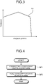
- FIG. 3 is a diagram illustrating a torque line diagram of the engine 7 according to the present embodiment.
- An upper limit torque characteristic of the engine 7 is prescribed by a maximum output torque line La.
- the engine control unit 41 controls the injector 23 based on the upper limit torque characteristic and engine target output.
- the engine control unit 41 adjusts a fuel injection amount with respect to the engine 7 so that engine speed and torque of the engine 7 do not exceed the maximum output torque line La.
- an injector correction coefficient for correcting a relationship between a fuel injection amount, engine speed and torque so that prescribed engine speed and torque are generated in the engine 7 when fuel is injected from the injector 23 in a prescribed fuel injection amount.
- the injector correction coefficient is a fixed value unambiguously defined at the time of shipment of the wheel loader 1 in a factory that produces the wheel loader 1, and is stored in the injection data storage unit 44.
- the first fuel data calculation unit 43 calculates first fuel data D1 related to fuel consumption.
- the first fuel data calculation unit 43 calculates the first fuel data D1 at least based on a fuel injection amount injected to the engine 7.
- the first fuel data D1 includes average fuel consumption Daf1 indicating an average fuel consumption rate in an operating time T of the engine 7 that is provided between prescribed start time point ta and end time point tb.
- the first fuel data calculation unit 43 converts a fuel injection amount represented in weight [mg/stroke], into a fuel injection amount represented in volume [mm 3 /stroke].
- the timer 61 can measure the operating time T.
- the first fuel data calculation unit 43 can calculate the first fuel data D1 indicating the average fuel consumption Daf1 [L/h] in the operating time T, based on a fuel injection amount [mm 3 /stroke], the number of fuel injections [stroke/s], and the operating time T.
- the first fuel data D1 may include an accumulated fuel consumption amount Dcf1 in the operating time T of the engine 7 that is provided between the prescribed start time point ta and end time point tb.
- the first fuel data calculation unit 43 can calculate the first fuel data D1 indicating the accumulated fuel consumption amount Dcf1 in the operating time T, based on a fuel injection amount, the number of fuel injections, and the operating time T.
- the sensor data acquisition unit 51 acquires detection data of the fuel sensor 21 and detection data of the speed sensor 22.
- the fuel sensor 21 detects the fuel amount M in the fuel tank 8 at a prescribed cycle, and outputs detection data to the sensor data acquisition unit 51.
- the speed sensor 22 detects travel speed V of the work vehicle 1 at a prescribed cycle, and outputs detection data to the sensor data acquisition unit 51.
- the second fuel data calculation unit 52 calculates second fuel data D2 related to fuel consumption, based on the detection data acquired by the sensor data acquisition unit 51.
- the second fuel data calculation unit 52 calculates the second fuel data D2 at least based on a change amount of the fuel amount M in the fuel tank 8 that has been detected by the fuel sensor 21.
- the second fuel data D2 includes fuel consumption Daf2 indicating a fuel consumption rate in the operating time T of the engine 7 that is provided between the prescribed start time point ta and end time point tb.
- the timer 61 can measure the operating time T.
- the second fuel data calculation unit 52 can calculate the second fuel data D2 indicating the fuel consumption Daf2 in the operating time T, based on the respective fuel amounts M in the fuel tank 8 at the start time point ta and the end time point tb of the operating time T, and the operating time T.
- the second fuel data calculation unit 52 can calculate the fuel consumption Daf2 [L/h] based on a difference [L] between a fuel amount Ma in the fuel tank 8 at the start time point ta of the operating time T, and a fuel amount Mb in the fuel tank 8 at the end time point tb of the operating time T, and the operating time T [h].
- the second fuel data D2 may include a fuel consumption amount Dcf2 in the operating time T of the engine 7 that is provided between the prescribed start time point ta and end time point tb.
- the second fuel data calculation unit 52 can calculate the second fuel data D2 indicating the fuel consumption amount Dcf2, based on the respective fuel amounts M in the fuel tank 8 at the start time point ta and the end time point tb of the operating time T.
- the correction coefficient calculation unit 53 calculates a correction coefficient kt to be used in the calculation of fuel consumption data Df, based the first fuel data D1 and the second fuel data D2.
- the correction coefficient calculation unit 53 calculates, as the correction coefficient kt, a ratio between the first fuel data D1 and the second fuel data D2.
- the correction coefficient calculation unit 53 calculates, as the correction coefficient kt, [Daf1/Daf2] being a ratio between the average fuel consumption consumption rate Daf1 and the fuel consumption consumption rate Daf2.
- the correction coefficient calculation unit 53 calculates, as the correction coefficient kt, [Dcf1/Dcf2] being a ratio between the accumulated fuel consumption amount Dcf1 and the fuel consumption amount Dcf2.
- the first fuel data D1 is the average fuel consumption Daf1
- the second fuel data D2 is the fuel consumption Daf2.
- the second fuel data D2 indicating the fuel consumption Daf2 is represented by Formula (1).
- D2 Ma ⁇ Mb / T
- the first fuel data D1 indicating the average fuel consumption Daf1 is represented by Formula (2) based on the accumulated fuel consumption amount Dcf1 in the operating time T.
- D1 Dcf1/T
- the correction coefficient kt is a ratio between the first fuel data D1 and the second fuel data D2, and is represented by Formula (3).
- kt D2/D1
- the correction coefficient determination unit 54 determines whether the correction coefficient kt falls within a prescribed range R.
- the prescribed range R is 0.8 or more and 1.2 or less.
- the correction coefficient determination unit 54 determines whether the obtained correction coefficient Kt satisfies a condition of [0.8 ⁇ kt ⁇ 1.2]. For example, when the first fuel data D1 (the average fuel consumption Daf1 or the accumulated fuel consumption amount Dcf1) calculated by the first fuel data calculation unit 43, and the second fuel data D2 (the fuel consumption Daf2 or the fuel consumption amount Dcf2) match, the correction coefficient kt is 1, and satisfies the condition of falling within the prescribed range R.
- the correction coefficient kt falls below 0.8 or exceeds 1.2
- the correction coefficient kt falls outside the prescribed range R, and does not satisfy the condition.
- the fuel consumption data calculation unit 55 calculates the fuel consumption data Df indicating a fuel consumption rate, based on the correction coefficient kt determined to fall within the prescribed range R, and the first fuel data D1.
- the fuel consumption data calculation unit 55 calculates the fuel consumption data Df by multiplying the first fuel data D1 calculated by the first fuel data calculation unit 43, by the correction coefficient kt.
- the output unit 56 outputs the fuel consumption data Df calculated by the fuel consumption data calculation unit 55.
- the output unit 56 outputs the fuel consumption data Df to the display device 18 mounted on the wheel loader 1. In the present embodiment, after converting the fuel consumption data Df into display data displayable by the display device 18, the output unit 56 outputs the display data to the display device 18.
- the output unit 56 transmits the fuel consumption data Df to the external server 32 of the work vehicle 1.
- the output unit 56 outputs the fuel consumption data Df to the server 32 via the communication device 30.
- the output unit 56 may output the fuel consumption data Df to the readable/writable memory 63, and the memory 63 may accumulate the fuel consumption data Df.
- the output unit 56 may read out the fuel consumption data Df from the memory 63 at a preset timing, and output the fuel consumption data Df to the server 32 via the communication device 30.
- the correction coefficient storage unit 57 stores the correction coefficient kt determined by the correction coefficient determination unit 54 to fall within the prescribed range R.
- the fuel consumption data calculation unit 55 calculates the fuel consumption data Df based on the correction coefficient kt stored in the correction coefficient storage unit 57, and the first fuel data D1 calculated by the first fuel data calculation unit 43.
- the fuel consumption data calculation unit 55 calculates the fuel consumption data Df based on the correction coefficient kt calculated by the correction coefficient calculation unit 53, and the first fuel data D1 calculated by the first fuel data calculation unit 43.
- the fuel supply determination unit 58 determines whether fuel has been supplied to the fuel tank 8, based on the detection data of the fuel sensor 21. When it is determined, based on the detection data of the fuel sensor 21, that the fuel amount M stored in the fuel tank 8 increases, the fuel supply determination unit 58 determines that fuel has been supplied to the fuel tank 8. When it is determined that the fuel amount M stored in the fuel tank 8 decreases, the fuel supply determination unit 58 determines that fuel has not been supplied to the fuel tank 8. When it is determined by the fuel supply determination unit 58 that fuel has not been supplied to the fuel tank 8, the correction coefficient calculation unit 53 calculates the correction coefficient kt. When it is determined by the fuel supply determination unit 58 that fuel has been supplied to the fuel tank 8, the correction coefficient calculation unit 53 does not calculate the correction coefficient kt.
- the travel condition determination unit 59 determines whether the wheel loader 1 satisfies a prescribed travel condition.
- the travel condition includes a state in which the travel speed V of the wheel loader 1 is equal to or less than a speed threshold has continued for a prescribed time.
- the speed threshold is 1 [km/h]
- the prescribed time is 60[s].
- the travel condition includes a state in which the travel speed V of the wheel loader 1 is equal to or less than 1[km/h] has continued for 60 seconds.
- the fuel sensor 21 cannot stably measure the fuel amount M.
- a state in which the wheel loader 1 satisfies the prescribed travel condition becomes a state in which inertial force decrease, waving of the liquid surface of fuel stored in the fuel tank 8 stops, and the liquid surface is stable.
- the second fuel data calculation unit 52 calculates the second fuel data D2 based on a change amount of the fuel amount M in the fuel tank 8 that has been acquired by the sensor data acquisition unit 51 when the wheel loader 1 satisfies the prescribed travel condition.
- the travel condition determination unit 59 determines that the liquid surface of fuel in the fuel tank 8 is stable.
- the second fuel data calculation unit 52 calculates the second fuel data D2 based on the fuel amount M detected by the fuel sensor 21 when the liquid surface of fuel in the fuel tank 8 is stable.
- the fuel amount storage unit 60 stores the fuel amount M that has been acquired by the sensor data acquisition unit 51 when it is determined by the fuel supply determination unit 58 that fuel has not been supplied to the fuel tank 8.
- FIGS. 4 , 5 , and 6 are flowchart illustrating a fuel consumption measurement method according to the present embodiment.
- the fuel consumption measurement method includes a correction coefficient calculation phase SP1 of calculating the correction coefficient kt, and a fuel consumption data output phase SP2 of calculating the fuel consumption data Df based on the correction coefficient kt calculated in the correction coefficient calculation phase SP1.
- FIG. 5 is a flowchart illustrating the correction coefficient calculation phase SP1.
- FIG. 6 is a flowchart illustrating the fuel consumption data output phase SP2.
- the injection data acquisition unit 42 acquires, from the engine control unit 41, injection data including a fuel injection amount and the number of injections. In addition, the injection data acquisition unit 42 acquires, from the injection data storage unit 44, injection data including fuel specific weight and an injector correction coefficient (Step SA1).
- the first fuel data calculation unit 43 calculates the first fuel data D1.
- the first fuel data calculation unit 43 calculates, as the first fuel data D1, the accumulated fuel consumption amount Dcf1 in the operating time T of the engine 7 that is provided between the prescribed start time point ta and end time point tb (Step SA2) .
- the first fuel data calculation unit 43 converts a fuel injection amount represented in weight [mg/stroke], into a fuel injection amount represented in volume [mm 3 /stroke].
- the timer 61 can measure the operating time T.
- the first fuel data calculation unit 43 can calculate the first fuel data D1 indicating the accumulated fuel consumption amount Dcf1 in the operating time T, based on a fuel injection amount [mm 3 /stroke], the number of fuel injections [stroke/s], and the operating time T.
- the sensor data acquisition unit 51 acquires detection data of the travel speed V of the wheel loader 1 from the speed sensor 22, and acquires detection data of the fuel amount M in the fuel tank 8 from the fuel sensor 21 (Step SB1).
- the travel condition determination unit 59 determines whether the wheel loader 1 satisfies the prescribed travel condition, based on the detection data of the travel speed V of the wheel loader 1 (Step SB2).
- the travel condition includes a state in which the travel speed V of the wheel loader 1 is equal to or less than 1 [km/h] being the speed threshold has continued for 60 [s] being the prescribed time.
- Step SB2 When it is determined in Step SB2 that the wheel loader 1 satisfies the travel condition (Step SB2: Yes), the fuel supply determination unit 58 determines whether fuel has been supplied to the fuel tank 8, based on the detection data of the fuel amount M in the fuel tank 8. In other words, the fuel supply determination unit 58 determines whether the fuel amount M stored in the fuel tank 8 has decreased from that in the previous detection (Step SB3).
- Step SB3 When it is determined in Step SB3 that the fuel amount M stored in the fuel tank 8 increases (Step SB3: No), the fuel supply determination unit 58 determines that fuel has been supplied to the fuel tank 8. When it is determined that the fuel amount M stored in the fuel tank 8 decreases, the fuel supply determination unit 58 determines that fuel has not been supplied to the fuel tank 8.
- Step SB3 When it is determined in Step SB3 that the fuel amount M stored in the fuel tank 8 decreases (Step SB3: Yes), the fuel supply determination unit 58 determines whether a change amount of the fuel amount M that indicates a difference between the fuel amount M stored in the fuel amount storage unit 60, and the fuel amount M that has been acquired in Step SB1, and obtained when it is determined in Step SB2 that the travel condition is satisfied, and it is determined in Step SB3 that fuel has not been supplied to the fuel tank 8, is equal to or larger than a change amount threshold C (Step SB4).
- the change amount threshold C is 156 [L].
- the fuel amount M stored in the fuel amount storage unit 60 will be appropriately referred to as a previous fuel amount Ma
- the fuel amount M that has been acquired in Step SB1 and obtained when it is determined in Step SB2 that the travel condition is satisfied, and it is determined in Step SB3 that fuel has not been supplied to the fuel tank 8, will be appropriately referred to as a current fuel amount Mb.
- the previous fuel amount Ma corresponds to the fuel amount Ma measured at the start time point ta of the operating time T of the wheel loader 1.
- the current fuel amount Mb corresponds to the fuel amount Mb measured at the end time point tb of the operating time T of the wheel loader 1.
- Step SB4 When it is determined in Step SB4 that a change amount of the fuel amount M is equal to or larger than the change amount threshold C (Step SB4: Yes), the second fuel data calculation unit 52 calculates second fuel data based on the change amount of the fuel amount M in the fuel tank 8 (Step SB5).
- the second fuel data calculation unit 52 calculates, as the second fuel data D2, the fuel consumption Daf2 in the operating time T of the engine 7 that is provided between the prescribed start time point ta and end time point tb.
- the second fuel data calculation unit 52 can calculate the fuel consumption Daf2 [L/h] based on a difference [L] between the previous fuel amount Ma indicating the fuel amount M in the fuel tank 8 at the start time point ta of the operating time T, and the current fuel amount Mb indicating the fuel amount M in the fuel tank 8 at the end time point tb of the operating time T, and the operating time T [h].
- the second fuel data calculation unit 52 calculates the second fuel data D2 indicating the fuel consumption Daf2, based on Formula (1) described above.
- the correction coefficient calculation unit 53 calculates the correction coefficient kt based on the first fuel data D1 indicating the accumulated fuel consumption amount Dcf1 that has been calculated in Step SA2, and the second fuel data D2 indicating the fuel consumption Daf2 that has been calculated in Step SB5 (Step SB6).
- the correction coefficient calculation unit 53 calculates the correction coefficient kt based on Formulae (2) and (3) described above.
- the correction coefficient determination unit 54 determines whether the correction coefficient kt calculated in Step SB6 falls within the prescribed range R (Step SB7).
- the prescribed range R is 0.8 or more and 1.2 or less.
- the correction coefficient determination unit 54 determines whether the obtained correction coefficient Kt satisfies the condition of [0.8 ⁇ kt ⁇ 1.2].
- Step SB7 When it is determined in Step SB7 that the correction coefficient kt falls within the prescribed range R (Step SB7: Yes), the correction coefficient determination unit 54 stores the correction coefficient kt determined to fall within the prescribed range R, into the correction coefficient storage unit 57.
- the correction coefficient kt already stored in the correction coefficient storage unit 57 is updated with the new correction coefficient kt that has been calculated in Step SB6, and determined in Step SB7 to fall within the prescribed range R (Step SB8).
- Step SB7 When it is determined in Step SB7 that the correction coefficient kt does not fall within the prescribed range R (Step SB7: No), the correction coefficient determination unit 54 does not update the correction coefficient kt stored in the correction coefficient storage unit 57 (Step SB9).
- a previous correction coefficient kta indicating the correction coefficient kt calculated based on the previous fuel amount Ma is maintained in the correction coefficient storage unit 57.
- Step SB3 When it is determined in Step SB3 that fuel has been supplied to the fuel tank 8 (Step SB3: No), or when it is determined in Step SB3 that fuel has not been supplied to the fuel tank 8 and it is determined in Step SB4 that the fuel amount has decreased from the previous fuel amount Ma by more than the change amount threshold C, the previous fuel amount Ma already stored in the fuel amount storage unit 60 is updated with the current fuel amount Mb (Step SB10).
- Step SB2 When it is determined in Step SB2 that the wheel loader 1 does not satisfy the travel condition (Step SB2: No), or when it is determined in Step SB4 that the change amount of the fuel amount M is less than the change amount threshold C (Step SB4: No), the processing returns to the processing in Step SB1, and the correction coefficient calculation phase SP1 is repeated.
- the injection data acquisition unit 42 acquires, from the engine control unit 41, injection data including a fuel injection amount and the number of injections. In addition, the injection data acquisition unit 42 acquires, from the injection data storage unit 44, injection data including fuel specific weight and an injector correction coefficient (Step SA21).
- the first fuel data calculation unit 43 calculates the first fuel data D1.
- the first fuel data calculation unit 43 calculates, as the first fuel data D1, the average fuel consumption Daf1 in the operating time T of the engine 7 that is provided between the prescribed start time point ta and end time point tb (Step SA22).
- the fuel consumption data calculation unit 55 acquires, from the correction coefficient storage unit 57, the correction coefficient kt determined to fall within the prescribed range R (Step SB21).
- Step SB9 illustrated in FIG. 5 When it is determined in Step SB9 illustrated in FIG. 5 that the correction coefficient kt falls within the prescribed range R, a current correction coefficient ktb indicating the latest correction coefficient kt calculated based on the current fuel amount Mb is stored in the correction coefficient storage unit 57.
- the fuel consumption data calculation unit 55 acquires the current correction coefficient ktb stored in the correction coefficient storage unit 57.
- the correction coefficient storage unit 57 is not updated (Step SB13), and the previous correction coefficient kta calculated based on the previous fuel amount Ma is stored in the correction coefficient storage unit 57.
- the fuel consumption data calculation unit 55 acquires the previous correction coefficient kta stored in the correction coefficient storage unit 57.
- the fuel consumption data calculation unit 55 calculates the fuel consumption data Df based on the correction coefficient kt acquired from the correction coefficient storage unit 57, and the first fuel data D1 calculated in Step SA22 (Step SB22).
- the fuel consumption data calculation unit 55 calculates the fuel consumption data Df by multiplying the first fuel data D1 by the correction coefficient kt.
- the output unit 56 outputs the fuel consumption data Df calculated by the fuel consumption data calculation unit 55, to the display device 18 and the server 32 (Step SB23). Furthermore, the output unit 56 may output the fuel consumption data Df to the memory 63, and the memory 63 may accumulate the fuel consumption data Df.
- FIG. 7 is a block diagram illustrating a computer system 1000 according to the present embodiment.
- the computer system 1000 includes a processor 1001 such as a Central Processing Unit (CPU), a main memory 1002 including a nonvolatile memory such as a Read Only Memory (ROM), and a volatile memory such as a Random Access Memory (RAM), a storage 1003, and an interface 1004 including an input/output circuit.
- the functions of the engine control device 40A, the data processing device 40B, and the server 32 that have been described above are stored in the storage 1003 as programs.
- the processor 1001 reads out the programs from the storage 1003, loads the programs onto the main memory 1002, and executes the above-described processing according to the programs.
- the programs may be delivered to the computer system 1000 via a network.
- the first fuel data D1 is calculated based on a fuel injection amount injected to the engine 7.
- the second fuel data D2 is calculated based on a change amount (decrease amount) of the fuel amount M in the fuel tank 8.
- the first fuel data D1 and the second fuel data D2 are compared, and when the first fuel data D1 and the second fuel data D2 are equal or proximate, that is to say, when a ratio between the first fuel data D1 and the second fuel data D2 is 1 or proximate to 1 (when falling within the prescribed range R), the ratio between the first fuel data D1 and the second fuel data D2 is adopted as the correction coefficient kt.
- accurate fuel consumption data Df can be obtained in real time by correcting the first fuel data D1 calculated based on the fuel injection amount injected to the engine 7, using the correction coefficient kt calculated in the correction coefficient calculation phase SP1.
- the correction coefficient kt is calculated based on the fuel amount M measured when the wheel loader 1 satisfies the travel condition, when the fuel tank 8 of the wheel loader 1 is inclined, there is a high possibility that the liquid surface of the stored fuel is also largely inclined, and it becomes difficult for the fuel sensor 21 to detect an accurate fuel amount M.
- the fuel amount M detected by the fuel sensor 21 is inaccurate, there is a high possibility that the second fuel data D2 is also inaccurate.
- the first fuel data D1 and the second fuel data D2 are compared, and when the first fuel data D1 and the second fuel data D2 are equal or proximate, the correction coefficient kt is calculated so as to be usable for obtaining fuel consumption. This can suppress the occurrence of such a failure that the correction coefficient kt is calculated based on inaccurate second fuel data D2.
- the first fuel data D1 and the second fuel data D2 are not proximate, that is to say, when a ratio between the first fuel data D1 and the second fuel data D2 does not fall within the prescribed range R, by correcting the first fuel data D1 based on the previous correction coefficient kta stored in the correction coefficient storage unit 57, deterioration in measurement accuracy that is caused when the fuel consumption data Df is measured in real time can be suppressed.
- the work vehicle 1 is assumed to be a wheel loader.
- the work vehicle 1 may be a dump truck that frequently repeats traveling and stop in a work.
- the work vehicle 1 may be at least one of a bulldozer, a motor grader, an engine-type forklift, and an excavator that frequently repeat driving and driving stop of a service machine in a work, or frequently repeat traveling and stop.
Landscapes
- Engineering & Computer Science (AREA)
- Chemical & Material Sciences (AREA)
- Combustion & Propulsion (AREA)
- Mechanical Engineering (AREA)
- General Engineering & Computer Science (AREA)
- Physics & Mathematics (AREA)
- Fluid Mechanics (AREA)
- General Physics & Mathematics (AREA)
- Combined Controls Of Internal Combustion Engines (AREA)
- Measuring Volume Flow (AREA)
Description
- The present invention relates to a fuel consumption measurement system of a work vehicle and a fuel consumption measurement method of a work vehicle. Background
- There is known a technology of displaying a fuel consumption rate (fuel consumption) of an engine in real time on a display device mounted on a passenger vehicle (see for example
JP 2015-200616 A -
DE 10 2015 206 373 A1 discloses the features of the preamble ofclaim 1 and refers to a device for computing the efficiency of fuel consumption. To this end, the change in the amount of fuel in a fuel tank is continuously monitored. A current consumption rate is calculated based on the result of such a measurement.
US 4 437 342 A refers to a fault diagnostic system arranged to detect faults in a fuel system of an engine with an electronic fuel injection system by monitoring the quantities of fuel consumed during a time interval. Hereto, a fuel consumption quantity and a fuel injection quantity during the same time interval are compared. If the difference therebetween is larger than a predetermined permissible range, it is decided that there is some fault somewhere in the fuel system, and an indication signals is produced.
JP S63 200017 A - Also in a work vehicle, it is desired to measure fuel consumption of an engine in real time and highly accurately. In a work of a work vehicle, in many cases, the work vehicle frequently repeats the driving and stop of a service machine, and frequently repeats traveling and stop. Thus, there is a high possibility that a drive state of the engine of the work vehicle frequently changes. In other words, a fuel injection amount injected to the engine frequently changes according to service content of the work vehicle. In addition, an engine control device for controlling the engine outputs a fuel injection command to a fuel injection device, but it is difficult for the fuel injection device to inject fuel in the same amount as a fuel injection amount indicated by the fuel injection command. Accordingly, even if fuel consumption is tried to be obtained by accumulating the fuel injection amount itself that is indicated by the fuel injection command, due to the difficulty in sensing of a fuel injection amount changing frequently, and limitation on response performance of the fuel injection device, there is a possibility that only fuel consumption with bad accuracy can be measured as fuel consumption of the work vehicle.
- The object of the present invention is to suppress deterioration in fuel consumption measurement accuracy of a work vehicle.
- According to a first aspect of the present invention, a fuel consumption measurement system of a work vehicle, comprises: a first fuel data calculation unit configured to calculate first fuel data related to fuel consumption, based on a fuel injection amount injected to an engine; a second fuel data calculation unit configured to calculate second fuel data related to fuel consumption, based on a change amount of a fuel amount in a fuel tank; a correction coefficient calculation unit configured to calculate a correction coefficient based on the first fuel data and the second fuel data; a correction coefficient determination unit configured to determine whether the correction coefficient falls within a prescribed range; a fuel consumption data calculation unit configured to calculate fuel consumption data indicating a fuel consumption rate, based on the correction coefficient determined to fall within the prescribed range, and the first fuel data; and a travel condition determination unit configured to determine whether a work vehicle satisfies a prescribed travel condition, wherein the second fuel data calculation unit is configured to calculate the second fuel data based on a change amount of a fuel amount in the fuel tank that has been acquired when the work vehicle satisfies the travel condition, wherein the travel condition includes a state in which travel speed of the work vehicle is equal to or smaller than a speed threshold has continued for a prescribed time; and a correction coefficient storage unit configured to store the correction coefficient determined to fall within the prescribed range, wherein when it is determined that the correction coefficient calculated by the correction coefficient calculation unit does not fall within a prescribed range, the fuel consumption data calculation unit calculates the fuel consumption data based on the correction coefficient stored in the correction coefficient storage unit, and the first fuel data.
- Preferred embodiments of the fuel consumption measurement system are described in
dependent claims 2 to 8.
According to a second aspect of the present invention, a fuel consumption measurement method of a work vehicle comprises the following steps: calculating first fuel data related to fuel consumption, based on a fuel injection amount injected to an engine; determining whether a work vehicle satisfies a prescribed travel condition, wherein the travel condition includes a state in which travel speed of the work vehicle is equal to or smaller than a speed threshold has continued for a prescribed time; calculating second fuel data related to fuel consumption, based on a change amount of a fuel amount in a fuel tank that has been acquired when the work vehicle satisfies the travel condition; calculating a correction coefficient based on the first fuel data and the second fuel data; determining whether the correction coefficient falls within a prescribed range; and calculating fuel consumption data indicating a fuel consumption rate, based on the correction coefficient determined to fall within the prescribed range, and the first fuel data; storing the correction coefficient determined to fall within the prescribed range on a correction coefficient storage unit; determining whether the correction coefficient does not fall within a prescribed range; and calculating fuel consumption data, based on the correction coefficient stored in the correction coefficient storage unit, and the first fuel data. - According to the present invention, deterioration in fuel consumption measurement accuracy of a work vehicle can be suppressed.
-
-
FIG. 1 is a side view illustrating a work vehicle according to an embodiment. -
FIG. 2 is a functional block diagram illustrating a fuel consumption measurement system according to an embodiment. -
FIG. 3 is a diagram illustrating a torque line diagram of an engine according to an embodiment. -
FIG. 4 is a flowchart illustrating a fuel consumption measurement method according to an embodiment. -
FIG. 5 is a flowchart illustrating the fuel consumption measurement method according to an embodiment. -
FIG. 6 is a flowchart illustrating the fuel consumption measurement method according to an embodiment. -
FIG. 7 is a block diagram illustrating a computer system according to an embodiment. - An embodiment according to the present invention will be described below with reference to the drawings. Nevertheless, the present invention is not limited to this. Components in the embodiment to be described below can be appropriately combined. In addition, some of components are not used in some cases.
-
FIG. 1 is a side view illustrating awork vehicle 1 according to the present embodiment. In the present embodiment, thework vehicle 1 is awheel loader 1, which is one type of an articulated work vehicle. Thewheel loader 1 loads an excavated object scooped by abucket 12, onto a transporter vehicle, or discharges the excavated object to a predetermined discharge location. - As illustrated in
FIG. 1 , thewheel loader 1 includes avehicle body 2, acab 3, a travel apparatus 4, anengine 7, afuel tank 8, anoil pressure pump 9, aservice machine 10, afuel sensor 21, aspeed sensor 22, acommunication device 30, and a fuelconsumption measurement system 50. - The
vehicle body 2 includes a vehicle body anterior part 2F and a vehicle bodyposterior part 2R. Thecab 3 is supported on the vehicle bodyposterior part 2R. A driver'scabin 3R is provided in thecab 3. Thewheel loader 1 is driven by an operator who has got onto the driver'scabin 3R. - The
engine 7, thefuel tank 8, and theoil pressure pump 9 are mounted on thevehicle body 2. Theengine 7 includes a diesel engine. Fuel stored in thefuel tank 8 is supplied to theengine 7. Thefuel tank 8 is disposed on the lower part of the vehicle bodyposterior part 2R. Theengine 7 includes aninjector 23. Theinjector 23 injects fuel to theengine 7. By fuel being supplied to theengine 7, theengine 7 is driven. Theoil pressure pump 9 is connected to theengine 7. By theengine 7 being driven, theoil pressure pump 9 is driven. Operating oil discharged from theoil pressure pump 9 is supplied to a boom cylinder 13 and abucket cylinder 14 for moving theservice machine 10, a steering cylinder for swinging thewheel loader 1, and the like. - The
fuel sensor 21 detects a fuel amount M indicating an amount of fuel stored in thefuel tank 8. The fuel amount M may be volume of fuel, or may be weight of fuel. The fuel amount M indicates a fuel remaining amount in thefuel tank 8. By detecting the height of a surface of fuel stored in thefuel tank 8, thefuel sensor 21 detects the fuel amount M stored in thefuel tank 8. Thefuel sensor 21 includes a float floating in fuel stored in thefuel tank 8, and a detector that detects a position of the float. As a detection method of the detector, at least one of a printing resistance method, a winding resistance method, and an electrostatic capacitance method is exemplified. - The travel apparatus 4 supports the
vehicle body 2. The travel apparatus 4 includes anarticulating mechanism 19 andwheels 5. The articulatingmechanism 19 couples the vehicle body anterior part 2F and the vehicle bodyposterior part 2R so as to be bendable. The articulatingmechanism 19 includes a steering cylinder. By the steering cylinder extending and contracting, thevehicle body 2 bends. By thevehicle body 2 bends, thewheel loader 1 swings. Thewheels 5 rotate by driving power generated by theengine 7.Tires 6 are attached to thewheels 5. Thewheels 5 include left and rightfront wheels 5F supported on the vehicle body anterior part 2F, and left and rightrear wheels 5R supported on the vehicle bodyposterior part 2R. Thetires 6 includefront tires 6F attached to thefront wheels 5F, andrear tires 6R attached to therear wheels 5R. By thewheels 5 rotating, thewheel loader 1 travels on a road surface RS. Thespeed sensor 22 detects travel speed of thewheel loader 1. - The
service machine 10 is supported on the vehicle body anterior part 2F. Theservice machine 10 includes aboom 11 swingably coupled to thevehicle body 2, thebucket 12 swingably coupled to theboom 11, abell crank 15, and alink 16. - The
boom 11 vertically swings by driving power generated by the boom cylinder 13. The boom cylinder 13 operates by operating oil discharged from theoil pressure pump 9. One end portion of the boom cylinder 13 is coupled to thevehicle body 2. Another end portion of the boom cylinder 13 is coupled to theboom 11. - The
bucket 12 is a work tool having atip portion 12B including a blade edge. Thebucket 12 is disposed anterior to thefront tires 6F. Thebucket 12 is coupled to a tip portion of theboom 11. Thebucket 12 swings by driving power generated by thebucket cylinder 14. Thebucket cylinder 14 operates by operating oil discharged from theoil pressure pump 9. A center portion of the bell crank 15 is rotatably coupled to theboom 11. One end portion of thebucket cylinder 14 is coupled to thevehicle body 2. Another end portion of thebucket cylinder 14 is coupled to one end portion of thebell crank 15. Another end portion of the bell crank 15 is coupled to thebucket 12 via thelink 16. - In the driver's
cabin 3R, a driver seat on which an operator is seated, an operatingdevice 17 to be operated by the operator, and adisplay device 18 are provided. The operatingdevice 17 includes an accelerator pedal, a brake pedal, a steering lever, a forward/backward changeover switch, and a service machine operating lever. - By operating the accelerator pedal, the brake pedal, the steering lever, and the forward/backward changeover switch of the operating
device 17, the operator can execute driving, braking, swinging, and forward/backward changeover of the travel apparatus 4. - By operating the accelerator pedal and the brake pedal of the operating
device 17, the operator can execute driving, braking, and travel speed adjustment of the travel apparatus 4. By operating the steering lever of the operatingdevice 17, the operator can execute swinging of thewheel loader 1, and by operating a forward/backward changeover lever, the operator can execute changeover of forward/backward movement of thewheel loader 1. - By operating the service machine operating lever of the operating
device 17, the operator can execute actuation of the boom cylinder 13 and actuation of thebucket cylinder 14. By the boom cylinder 13 extending and contracting, theboom 11 performs an upward operation or a downward operation. By thebucket cylinder 14 extending and contracting, thebucket 12 performs a tilt operation or a dump operation. - The
display device 18 displays display data. Thedisplay device 18 includes a flat-panel display such as a liquid crystal display (LCD) or an organic electroluminescence display (OELD). - The
communication device 30 can communicate with anexternal server 32 of thework vehicle 1 via acommunication network 31. As thecommunication network 31, at least one of a Local Area Network (LAN), internet, a mobile telephone communication network, and a satellite communication network is exemplified. Theserver 32 includes a computer system provided on the outside of thework vehicle 1. -
FIG. 2 is a functional block diagram illustrating the fuelconsumption measurement system 50 according to the present embodiment. The fuelconsumption measurement system 50 measures a fuel consumption rate (fuel consumption) of thework vehicle 1. In thework vehicle 1, fuel consumption indicates a fuel consumption amount per unit time, and a unit is [L/h]. - The fuel
consumption measurement system 50 includes acontrol apparatus 40. Thecontrol apparatus 40 includes a computer system. Thecontrol apparatus 40 is mounted on thevehicle body 2. Thecontrol apparatus 40 controls thework vehicle 1. Thecontrol apparatus 40 includes anengine control device 40A that executes control of theengine 7, and adata processing device 40B that executes calculation of fuel consumption of thework vehicle 1, control of thedisplay device 18, output of fuel consumption data, and the like. - The
engine control device 40A includes an engine control unit 41, an injection data acquisition unit 42, a first fueldata calculation unit 43, an injectiondata storage unit 44, and atimer 61. - The
data processing device 40B includes a sensordata acquisition unit 51, a second fueldata calculation unit 52, a correction coefficient calculation unit 53, a correction coefficient determination unit 54, a fuel consumptiondata calculation unit 55, anoutput unit 56, a correctioncoefficient storage unit 57, a fuelsupply determination unit 58, a travelcondition determination unit 59, a fuelamount storage unit 60, atimer 62, and amemory 63. - The engine control unit 41 outputs a control command for controlling the
injector 23. The engine control unit 41 outputs a control command based on an operation amount of the accelerator pedal of the operatingdevice 17. The control command output from the engine control unit 41 includes a control command for controlling a fuel injection amount injected to theengine 7, and a control command for controlling the number of fuel injections per unit time. The fuel injection amount indicates weight of fuel injected in one injection operation of theinjector 23, and a unit is [mg/stroke]. The number of fuel injections indicates the number of injection operations of theinjector 23 that are executed per unit time, and a unit is [stroke/s]. - The injection data acquisition unit 42 acquires injection data related to fuel injection performed by the
injector 23. The injection data includes a fuel injection amount and the number of fuel injections. In addition, the injection data includes fuel specific weight and an injector correction coefficient. The fuel specific weight indicates specific weight of fuel, and a unit is [mg/mm3]. The fuel specific weight is known data that can be derived from physicality data of fuel stored in thefuel tank 8, and is stored in the injectiondata storage unit 44. The fuel injection amount acquired by the injection data acquisition unit 42 is weight of fuel injected in one injection operation of theinjector 23. Based on the fuel specific weight, a fuel injection amount represented in weight [mg] is converted into a fuel injection amount represented in volume [mm3]. In other words, based on the fuel specific weight, volume [mm3/stroke] of fuel injected in one injection operation of theinjector 23 is calculated as a fuel injection amount. -
FIG. 3 is a diagram illustrating a torque line diagram of theengine 7 according to the present embodiment. An upper limit torque characteristic of theengine 7 is prescribed by a maximum output torque line La. The engine control unit 41 controls theinjector 23 based on the upper limit torque characteristic and engine target output. The engine control unit 41 adjusts a fuel injection amount with respect to theengine 7 so that engine speed and torque of theengine 7 do not exceed the maximum output torque line La. - In the present embodiment, there is prescribed an injector correction coefficient for correcting a relationship between a fuel injection amount, engine speed and torque so that prescribed engine speed and torque are generated in the
engine 7 when fuel is injected from theinjector 23 in a prescribed fuel injection amount. For example, the injector correction coefficient is a fixed value unambiguously defined at the time of shipment of thewheel loader 1 in a factory that produces thewheel loader 1, and is stored in the injectiondata storage unit 44. - Based on the injection data, the first fuel
data calculation unit 43 calculates first fuel data D1 related to fuel consumption. The first fueldata calculation unit 43 calculates the first fuel data D1 at least based on a fuel injection amount injected to theengine 7. - The first fuel data D1 includes average fuel consumption Daf1 indicating an average fuel consumption rate in an operating time T of the
engine 7 that is provided between prescribed start time point ta and end time point tb. In the present embodiment, based on fuel specific weight, the first fueldata calculation unit 43 converts a fuel injection amount represented in weight [mg/stroke], into a fuel injection amount represented in volume [mm3/stroke]. Thetimer 61 can measure the operating time T. In the case of calculating the average fuel consumption Daf1, the first fueldata calculation unit 43 can calculate the first fuel data D1 indicating the average fuel consumption Daf1 [L/h] in the operating time T, based on a fuel injection amount [mm3/stroke], the number of fuel injections [stroke/s], and the operating time T. - In addition, the first fuel data D1 may include an accumulated fuel consumption amount Dcf1 in the operating time T of the
engine 7 that is provided between the prescribed start time point ta and end time point tb. In the case of calculating the accumulated fuel consumption amount Dcf1, the first fueldata calculation unit 43 can calculate the first fuel data D1 indicating the accumulated fuel consumption amount Dcf1 in the operating time T, based on a fuel injection amount, the number of fuel injections, and the operating time T. - The sensor
data acquisition unit 51 acquires detection data of thefuel sensor 21 and detection data of thespeed sensor 22. Thefuel sensor 21 detects the fuel amount M in thefuel tank 8 at a prescribed cycle, and outputs detection data to the sensordata acquisition unit 51. Thespeed sensor 22 detects travel speed V of thework vehicle 1 at a prescribed cycle, and outputs detection data to the sensordata acquisition unit 51. - The second fuel
data calculation unit 52 calculates second fuel data D2 related to fuel consumption, based on the detection data acquired by the sensordata acquisition unit 51. The second fueldata calculation unit 52 calculates the second fuel data D2 at least based on a change amount of the fuel amount M in thefuel tank 8 that has been detected by thefuel sensor 21. - The second fuel data D2 includes fuel consumption Daf2 indicating a fuel consumption rate in the operating time T of the
engine 7 that is provided between the prescribed start time point ta and end time point tb. Thetimer 61 can measure the operating time T. In the case of measuring the fuel consumption Daf2, the second fueldata calculation unit 52 can calculate the second fuel data D2 indicating the fuel consumption Daf2 in the operating time T, based on the respective fuel amounts M in thefuel tank 8 at the start time point ta and the end time point tb of the operating time T, and the operating time T. In other words, the second fueldata calculation unit 52 can calculate the fuel consumption Daf2 [L/h] based on a difference [L] between a fuel amount Ma in thefuel tank 8 at the start time point ta of the operating time T, and a fuel amount Mb in thefuel tank 8 at the end time point tb of the operating time T, and the operating time T [h]. - In addition, the second fuel data D2 may include a fuel consumption amount Dcf2 in the operating time T of the
engine 7 that is provided between the prescribed start time point ta and end time point tb. In the case of calculating the fuel consumption amount Dcf2, the second fueldata calculation unit 52 can calculate the second fuel data D2 indicating the fuel consumption amount Dcf2, based on the respective fuel amounts M in thefuel tank 8 at the start time point ta and the end time point tb of the operating time T. - The correction coefficient calculation unit 53 calculates a correction coefficient kt to be used in the calculation of fuel consumption data Df, based the first fuel data D1 and the second fuel data D2. The correction coefficient calculation unit 53 calculates, as the correction coefficient kt, a ratio between the first fuel data D1 and the second fuel data D2. When the first fuel data D1 is the average fuel consumption Daf1 in the operating time T of the
engine 7, and the second fuel data D2 is the fuel consumption Daf2 in the operating time T of theengine 7, the correction coefficient calculation unit 53 calculates, as the correction coefficient kt, [Daf1/Daf2] being a ratio between the average fuel consumption consumption rate Daf1 and the fuel consumption consumption rate Daf2. When the first fuel data D1 includes the accumulated fuel consumption amount Dcf1 in the operating time T of theengine 7, and the second fuel data D2 includes the fuel consumption amount Dcf2 in the operating time T of theengine 7, the correction coefficient calculation unit 53 calculates, as the correction coefficient kt, [Dcf1/Dcf2] being a ratio between the accumulated fuel consumption amount Dcf1 and the fuel consumption amount Dcf2. - An example of a calculation method of the correction coefficient kt will be described. Hereinafter, it is assumed that the first fuel data D1 is the average fuel consumption Daf1, and the second fuel data D2 is the fuel consumption Daf2.
- When the fuel amount M at the start time point ta of the operating time T is the fuel amount Ma, and the fuel amount M at the end time point tb which is a time point at which the operating time T has elapsed thereafter is the fuel amount Mb, the second fuel data D2 indicating the fuel consumption Daf2 is represented by Formula (1).

- The first fuel data D1 indicating the average fuel consumption Daf1 is represented by Formula (2) based on the accumulated fuel consumption amount Dcf1 in the operating time T.

- The correction coefficient kt is a ratio between the first fuel data D1 and the second fuel data D2, and is represented by Formula (3).

- The correction coefficient determination unit 54 determines whether the correction coefficient kt falls within a prescribed range R. In the present embodiment, the prescribed range R is 0.8 or more and 1.2 or less. In other words, the correction coefficient determination unit 54 determines whether the obtained correction coefficient Kt satisfies a condition of [0.8 ≤ kt ≤ 1.2]. For example, when the first fuel data D1 (the average fuel consumption Daf1 or the accumulated fuel consumption amount Dcf1) calculated by the first fuel
data calculation unit 43, and the second fuel data D2 (the fuel consumption Daf2 or the fuel consumption amount Dcf2) match, the correction coefficient kt is 1, and satisfies the condition of falling within the prescribed range R. When the first fuel data D1 (the average fuel consumption Daf1 or the accumulated fuel consumption amount Dcf1) calculated by the first fueldata calculation unit 43 and the second fuel data D2 (the fuel consumption Daf2 or the fuel consumption amount Dcf2) are different, or the obtained correction coefficient kt falls below 0.8 or exceeds 1.2, the correction coefficient kt falls outside the prescribed range R, and does not satisfy the condition. - The fuel consumption
data calculation unit 55 calculates the fuel consumption data Df indicating a fuel consumption rate, based on the correction coefficient kt determined to fall within the prescribed range R, and the first fuel data D1. The fuel consumptiondata calculation unit 55 calculates the fuel consumption data Df by multiplying the first fuel data D1 calculated by the first fueldata calculation unit 43, by the correction coefficient kt. - The
output unit 56 outputs the fuel consumption data Df calculated by the fuel consumptiondata calculation unit 55. Theoutput unit 56 outputs the fuel consumption data Df to thedisplay device 18 mounted on thewheel loader 1. In the present embodiment, after converting the fuel consumption data Df into display data displayable by thedisplay device 18, theoutput unit 56 outputs the display data to thedisplay device 18. - In addition, the
output unit 56 transmits the fuel consumption data Df to theexternal server 32 of thework vehicle 1. Theoutput unit 56 outputs the fuel consumption data Df to theserver 32 via thecommunication device 30. In addition, theoutput unit 56 may output the fuel consumption data Df to the readable/writable memory 63, and thememory 63 may accumulate the fuel consumption data Df. In this case, theoutput unit 56 may read out the fuel consumption data Df from thememory 63 at a preset timing, and output the fuel consumption data Df to theserver 32 via thecommunication device 30. - The correction
coefficient storage unit 57 stores the correction coefficient kt determined by the correction coefficient determination unit 54 to fall within the prescribed range R. When the correction coefficient kt calculated by the correction coefficient calculation unit 53 is determined by the correction coefficient determination unit 54 to fall outside the prescribed range R, the fuel consumptiondata calculation unit 55 calculates the fuel consumption data Df based on the correction coefficient kt stored in the correctioncoefficient storage unit 57, and the first fuel data D1 calculated by the first fueldata calculation unit 43. When the correction coefficient kt calculated by the correction coefficient calculation unit 53 is determined by the correction coefficient determination unit 54 to fall within the prescribed range R, the fuel consumptiondata calculation unit 55 calculates the fuel consumption data Df based on the correction coefficient kt calculated by the correction coefficient calculation unit 53, and the first fuel data D1 calculated by the first fueldata calculation unit 43. - The fuel
supply determination unit 58 determines whether fuel has been supplied to thefuel tank 8, based on the detection data of thefuel sensor 21. When it is determined, based on the detection data of thefuel sensor 21, that the fuel amount M stored in thefuel tank 8 increases, the fuelsupply determination unit 58 determines that fuel has been supplied to thefuel tank 8. When it is determined that the fuel amount M stored in thefuel tank 8 decreases, the fuelsupply determination unit 58 determines that fuel has not been supplied to thefuel tank 8. When it is determined by the fuelsupply determination unit 58 that fuel has not been supplied to thefuel tank 8, the correction coefficient calculation unit 53 calculates the correction coefficient kt. When it is determined by the fuelsupply determination unit 58 that fuel has been supplied to thefuel tank 8, the correction coefficient calculation unit 53 does not calculate the correction coefficient kt. - The travel
condition determination unit 59 determines whether thewheel loader 1 satisfies a prescribed travel condition. The travel condition includes a state in which the travel speed V of thewheel loader 1 is equal to or less than a speed threshold has continued for a prescribed time. In the present embodiment, the speed threshold is 1 [km/h], and the prescribed time is 60[s]. In other words, the travel condition includes a state in which the travel speed V of thewheel loader 1 is equal to or less than 1[km/h] has continued for 60 seconds. In a situation in which thewheel loader 1 repeats moving start and stop, because a liquid surface of fuel stored in thefuel tank 8 largely surges and waves due to inertial force, thefuel sensor 21 cannot stably measure the fuel amount M. On the other hand, a state in which thewheel loader 1 satisfies the prescribed travel condition becomes a state in which inertial force decrease, waving of the liquid surface of fuel stored in thefuel tank 8 stops, and the liquid surface is stable. - The second fuel
data calculation unit 52 calculates the second fuel data D2 based on a change amount of the fuel amount M in thefuel tank 8 that has been acquired by the sensordata acquisition unit 51 when thewheel loader 1 satisfies the prescribed travel condition. When a prescribed time elapses in a state in which thework vehicle 1 travels at low speed, or a state in which thework vehicle 1 is stopped, the travelcondition determination unit 59 determines that the liquid surface of fuel in thefuel tank 8 is stable. The second fueldata calculation unit 52 calculates the second fuel data D2 based on the fuel amount M detected by thefuel sensor 21 when the liquid surface of fuel in thefuel tank 8 is stable. - The fuel
amount storage unit 60 stores the fuel amount M that has been acquired by the sensordata acquisition unit 51 when it is determined by the fuelsupply determination unit 58 that fuel has not been supplied to thefuel tank 8. - Next, a fuel consumption measurement method according to the present embodiment will be described with reference to
FIGS. 4 ,5 , and6 . Each ofFIGS. 4 ,5 , and6 is a flowchart illustrating a fuel consumption measurement method according to the present embodiment. - As illustrated in
FIG. 4 , in the present embodiment, the fuel consumption measurement method includes a correction coefficient calculation phase SP1 of calculating the correction coefficient kt, and a fuel consumption data output phase SP2 of calculating the fuel consumption data Df based on the correction coefficient kt calculated in the correction coefficient calculation phase SP1.FIG. 5 is a flowchart illustrating the correction coefficient calculation phase SP1.FIG. 6 is a flowchart illustrating the fuel consumption data output phase SP2. - The correction coefficient calculation phase SP1 will be described with reference to
FIG. 5 . - In the
engine control device 40A, the injection data acquisition unit 42 acquires, from the engine control unit 41, injection data including a fuel injection amount and the number of injections. In addition, the injection data acquisition unit 42 acquires, from the injectiondata storage unit 44, injection data including fuel specific weight and an injector correction coefficient (Step SA1). - Based on the injection data, the first fuel
data calculation unit 43 calculates the first fuel data D1. In the present embodiment, the first fueldata calculation unit 43 calculates, as the first fuel data D1, the accumulated fuel consumption amount Dcf1 in the operating time T of theengine 7 that is provided between the prescribed start time point ta and end time point tb (Step SA2) . - Based on fuel specific weight, the first fuel
data calculation unit 43 converts a fuel injection amount represented in weight [mg/stroke], into a fuel injection amount represented in volume [mm3/stroke]. Thetimer 61 can measure the operating time T. In the case of calculating the accumulated fuel consumption amount Dcf1, the first fueldata calculation unit 43 can calculate the first fuel data D1 indicating the accumulated fuel consumption amount Dcf1 in the operating time T, based on a fuel injection amount [mm3/stroke], the number of fuel injections [stroke/s], and the operating time T. - In the
data processing device 40B, the sensordata acquisition unit 51 acquires detection data of the travel speed V of thewheel loader 1 from thespeed sensor 22, and acquires detection data of the fuel amount M in thefuel tank 8 from the fuel sensor 21 (Step SB1). - The travel
condition determination unit 59 determines whether thewheel loader 1 satisfies the prescribed travel condition, based on the detection data of the travel speed V of the wheel loader 1 (Step SB2). - The travel condition includes a state in which the travel speed V of the
wheel loader 1 is equal to or less than 1 [km/h] being the speed threshold has continued for 60 [s] being the prescribed time. - When it is determined in Step SB2 that the
wheel loader 1 satisfies the travel condition (Step SB2: Yes), the fuelsupply determination unit 58 determines whether fuel has been supplied to thefuel tank 8, based on the detection data of the fuel amount M in thefuel tank 8. In other words, the fuelsupply determination unit 58 determines whether the fuel amount M stored in thefuel tank 8 has decreased from that in the previous detection (Step SB3). - When it is determined in Step SB3 that the fuel amount M stored in the
fuel tank 8 increases (Step SB3: No), the fuelsupply determination unit 58 determines that fuel has been supplied to thefuel tank 8. When it is determined that the fuel amount M stored in thefuel tank 8 decreases, the fuelsupply determination unit 58 determines that fuel has not been supplied to thefuel tank 8. - When it is determined in Step SB3 that the fuel amount M stored in the
fuel tank 8 decreases (Step SB3: Yes), the fuelsupply determination unit 58 determines whether a change amount of the fuel amount M that indicates a difference between the fuel amount M stored in the fuelamount storage unit 60, and the fuel amount M that has been acquired in Step SB1, and obtained when it is determined in Step SB2 that the travel condition is satisfied, and it is determined in Step SB3 that fuel has not been supplied to thefuel tank 8, is equal to or larger than a change amount threshold C (Step SB4). - In the present embodiment, the change amount threshold C is 156 [L]. In the following description, the fuel amount M stored in the fuel
amount storage unit 60 will be appropriately referred to as a previous fuel amount Ma, and the fuel amount M that has been acquired in Step SB1, and obtained when it is determined in Step SB2 that the travel condition is satisfied, and it is determined in Step SB3 that fuel has not been supplied to thefuel tank 8, will be appropriately referred to as a current fuel amount Mb. The previous fuel amount Ma corresponds to the fuel amount Ma measured at the start time point ta of the operating time T of thewheel loader 1. The current fuel amount Mb corresponds to the fuel amount Mb measured at the end time point tb of the operating time T of thewheel loader 1. - When it is determined in Step SB4 that a change amount of the fuel amount M is equal to or larger than the change amount threshold C (Step SB4: Yes), the second fuel
data calculation unit 52 calculates second fuel data based on the change amount of the fuel amount M in the fuel tank 8 (Step SB5). - In the present embodiment, the second fuel
data calculation unit 52 calculates, as the second fuel data D2, the fuel consumption Daf2 in the operating time T of theengine 7 that is provided between the prescribed start time point ta and end time point tb. The second fueldata calculation unit 52 can calculate the fuel consumption Daf2 [L/h] based on a difference [L] between the previous fuel amount Ma indicating the fuel amount M in thefuel tank 8 at the start time point ta of the operating time T, and the current fuel amount Mb indicating the fuel amount M in thefuel tank 8 at the end time point tb of the operating time T, and the operating time T [h]. In other words, the second fueldata calculation unit 52 calculates the second fuel data D2 indicating the fuel consumption Daf2, based on Formula (1) described above. - The correction coefficient calculation unit 53 calculates the correction coefficient kt based on the first fuel data D1 indicating the accumulated fuel consumption amount Dcf1 that has been calculated in Step SA2, and the second fuel data D2 indicating the fuel consumption Daf2 that has been calculated in Step SB5 (Step SB6).
- In other words, the correction coefficient calculation unit 53 calculates the correction coefficient kt based on Formulae (2) and (3) described above.
- The correction coefficient determination unit 54 determines whether the correction coefficient kt calculated in Step SB6 falls within the prescribed range R (Step SB7).
- As described above, in the present embodiment, the prescribed range R is 0.8 or more and 1.2 or less. The correction coefficient determination unit 54 determines whether the obtained correction coefficient Kt satisfies the condition of [0.8 ≤ kt ≤ 1.2].
- When it is determined in Step SB7 that the correction coefficient kt falls within the prescribed range R (Step SB7: Yes), the correction coefficient determination unit 54 stores the correction coefficient kt determined to fall within the prescribed range R, into the correction
coefficient storage unit 57. - The correction coefficient kt already stored in the correction
coefficient storage unit 57 is updated with the new correction coefficient kt that has been calculated in Step SB6, and determined in Step SB7 to fall within the prescribed range R (Step SB8). - When it is determined in Step SB7 that the correction coefficient kt does not fall within the prescribed range R (Step SB7: No), the correction coefficient determination unit 54 does not update the correction coefficient kt stored in the correction coefficient storage unit 57 (Step SB9).
- In other words, a previous correction coefficient kta indicating the correction coefficient kt calculated based on the previous fuel amount Ma is maintained in the correction
coefficient storage unit 57. - When it is determined in Step SB3 that fuel has been supplied to the fuel tank 8 (Step SB3: No), or when it is determined in Step SB3 that fuel has not been supplied to the
fuel tank 8 and it is determined in Step SB4 that the fuel amount has decreased from the previous fuel amount Ma by more than the change amount threshold C, the previous fuel amount Ma already stored in the fuelamount storage unit 60 is updated with the current fuel amount Mb (Step SB10). - When it is determined in Step SB2 that the
wheel loader 1 does not satisfy the travel condition (Step SB2: No), or when it is determined in Step SB4 that the change amount of the fuel amount M is less than the change amount threshold C (Step SB4: No), the processing returns to the processing in Step SB1, and the correction coefficient calculation phase SP1 is repeated. - Next, the fuel consumption data output phase SP2 will be described with reference to
FIG. 6 . - In the
engine control device 40A, the injection data acquisition unit 42 acquires, from the engine control unit 41, injection data including a fuel injection amount and the number of injections. In addition, the injection data acquisition unit 42 acquires, from the injectiondata storage unit 44, injection data including fuel specific weight and an injector correction coefficient (Step SA21). - Based on the injection data, the first fuel
data calculation unit 43 calculates the first fuel data D1. In the present embodiment, the first fueldata calculation unit 43 calculates, as the first fuel data D1, the average fuel consumption Daf1 in the operating time T of theengine 7 that is provided between the prescribed start time point ta and end time point tb (Step SA22). - The fuel consumption
data calculation unit 55 acquires, from the correctioncoefficient storage unit 57, the correction coefficient kt determined to fall within the prescribed range R (Step SB21). - When it is determined in Step SB9 illustrated in
FIG. 5 that the correction coefficient kt falls within the prescribed range R, a current correction coefficient ktb indicating the latest correction coefficient kt calculated based on the current fuel amount Mb is stored in the correctioncoefficient storage unit 57. The fuel consumptiondata calculation unit 55 acquires the current correction coefficient ktb stored in the correctioncoefficient storage unit 57. On the other hand, when it is determined in Step SB9 illustrated inFIG. 5 that the correction coefficient kt does not fall within the prescribed range R, the correctioncoefficient storage unit 57 is not updated (Step SB13), and the previous correction coefficient kta calculated based on the previous fuel amount Ma is stored in the correctioncoefficient storage unit 57. The fuel consumptiondata calculation unit 55 acquires the previous correction coefficient kta stored in the correctioncoefficient storage unit 57. - The fuel consumption
data calculation unit 55 calculates the fuel consumption data Df based on the correction coefficient kt acquired from the correctioncoefficient storage unit 57, and the first fuel data D1 calculated in Step SA22 (Step SB22). - The fuel consumption
data calculation unit 55 calculates the fuel consumption data Df by multiplying the first fuel data D1 by the correction coefficient kt. - The
output unit 56 outputs the fuel consumption data Df calculated by the fuel consumptiondata calculation unit 55, to thedisplay device 18 and the server 32 (Step SB23). Furthermore, theoutput unit 56 may output the fuel consumption data Df to thememory 63, and thememory 63 may accumulate the fuel consumption data Df. -
FIG. 7 is a block diagram illustrating acomputer system 1000 according to the present embodiment. Each of theengine control device 40A, thedata processing device 40B, and theserver 32 that have been described above includes thecomputer system 1000. Thecomputer system 1000 includes aprocessor 1001 such as a Central Processing Unit (CPU), amain memory 1002 including a nonvolatile memory such as a Read Only Memory (ROM), and a volatile memory such as a Random Access Memory (RAM), astorage 1003, and aninterface 1004 including an input/output circuit. The functions of theengine control device 40A, thedata processing device 40B, and theserver 32 that have been described above are stored in thestorage 1003 as programs. Theprocessor 1001 reads out the programs from thestorage 1003, loads the programs onto themain memory 1002, and executes the above-described processing according to the programs. In addition, the programs may be delivered to thecomputer system 1000 via a network. - As described above, according to the present embodiment, in the correction coefficient calculation phase SP1, the first fuel data D1 is calculated based on a fuel injection amount injected to the
engine 7. The second fuel data D2 is calculated based on a change amount (decrease amount) of the fuel amount M in thefuel tank 8. The first fuel data D1 and the second fuel data D2 are compared, and when the first fuel data D1 and the second fuel data D2 are equal or proximate, that is to say, when a ratio between the first fuel data D1 and the second fuel data D2 is 1 or proximate to 1 (when falling within the prescribed range R), the ratio between the first fuel data D1 and the second fuel data D2 is adopted as the correction coefficient kt. In the fuel consumption data output phase SP2, accurate fuel consumption data Df can be obtained in real time by correcting the first fuel data D1 calculated based on the fuel injection amount injected to theengine 7, using the correction coefficient kt calculated in the correction coefficient calculation phase SP1. - For example, even if the correction coefficient kt is calculated based on the fuel amount M measured when the
wheel loader 1 satisfies the travel condition, when thefuel tank 8 of thewheel loader 1 is inclined, there is a high possibility that the liquid surface of the stored fuel is also largely inclined, and it becomes difficult for thefuel sensor 21 to detect an accurate fuel amount M. When the fuel amount M detected by thefuel sensor 21 is inaccurate, there is a high possibility that the second fuel data D2 is also inaccurate. - In the present embodiment, the first fuel data D1 and the second fuel data D2 are compared, and when the first fuel data D1 and the second fuel data D2 are equal or proximate, the correction coefficient kt is calculated so as to be usable for obtaining fuel consumption. This can suppress the occurrence of such a failure that the correction coefficient kt is calculated based on inaccurate second fuel data D2.
- In the present embodiment, when the first fuel data D1 and the second fuel data D2 are not proximate, that is to say, when a ratio between the first fuel data D1 and the second fuel data D2 does not fall within the prescribed range R, by correcting the first fuel data D1 based on the previous correction coefficient kta stored in the correction
coefficient storage unit 57, deterioration in measurement accuracy that is caused when the fuel consumption data Df is measured in real time can be suppressed. - In addition, in the above-described embodiment, the
work vehicle 1 is assumed to be a wheel loader. Thework vehicle 1 may be a dump truck that frequently repeats traveling and stop in a work. In addition, thework vehicle 1 may be at least one of a bulldozer, a motor grader, an engine-type forklift, and an excavator that frequently repeat driving and driving stop of a service machine in a work, or frequently repeat traveling and stop. -
- 1
- WHEEL LOADER (WORK VEHICLE)
- 2
- VEHICLE BODY
- 2F
- VEHICLE BODY ANTERIOR PART
- 2R
- VEHICLE BODY POSTERIOR PART
- 3
- CAB
- 3R
- DRIVER'S CABIN
- 4
- TRAVEL APPARATUS
- 5
- WHEEL
- 5F
- FRONT WHEEL
- 5R
- REAR WHEEL
- 6
- TIRE
- 6F
- FRONT TIRE
- 6R
- REAR TIRE
- 7
- ENGINE
- 8
- FUEL TANK
- 9
- OIL PRESSURE PUMP
- 10
- WORK DEVICE
- 11
- BOOM
- 12
- BUCKET
- 12B
- TIP PORTION
- 13
- BOOM CYLINDER
- 14
- BUCKET CYLINDER
- 15
- BELL CRANK
- 16
- LINK
- 17
- OPERATING DEVICE
- 18
- DISPLAY DEVICE
- 19
- ARTICULATING MECHANISM
- 21
- FUEL SENSOR
- 22
- SPEED SENSOR
- 23
- INJECTOR
- 30
- COMMUNICATION DEVICE
- 31
- COMMUNICATION NETWORK
- 32
- SERVER (COMPUTER SYSTEM)
- 40
- CONTROL APPARATUS
- 40A
- ENGINE CONTROL DEVICE
- 40B
- DATA PROCESSING DEVICE
- 41
- ENGINE CONTROL UNIT
- 42
- INJECTION DATA ACQUISITION UNIT
- 43
- FIRST FUEL DATA CALCULATION UNIT
- 50
- FUEL CONSUMPTION MEASUREMENT SYSTEM
- 51
- SENSOR DATA ACQUISITION UNIT
- 52
- SECOND FUEL DATA CALCULATION UNIT
- 53
- CORRECTION COEFFICIENT CALCULATION UNIT
- 54
- CORRECTION COEFFICIENT DETERMINATION UNIT
- 55
- FUEL CONSUMPTION DATA CALCULATION UNIT
- 56
- OUTPUT UNIT
- 57
- CORRECTION COEFFICIENT STORAGE UNIT
- 58
- FUEL SUPPLY DETERMINATION UNIT
- 59
- TRAVEL CONDITION DETERMINATION UNIT
- 60
- FUEL AMOUNT STORAGE UNIT
- 61
- TIMER
- 62
- TIMER
- 63
- MEMORY
- D1
- FIRST FUEL DATA
- C
- CHANGE AMOUNT THRESHOLD
- Daf1
- AVERAGE FUEL CONSUMPTION
- Dcf1
- ACCUMULATED FUEL CONSUMPTION AMOUNT
- D2
- SECOND FUEL DATA
- Daf2
- FUEL CONSUMPTION
- Dcf2
- FUEL CONSUMPTION AMOUNT
- kt
- CORRECTION COEFFICIENT
- kta
- PREVIOUS CORRECTION COEFFICIENT
- ktb
- CURRENT CORRECTION COEFFICIENT
- M
- FUEL AMOUNT
- Ma
- FUEL AMOUNT (PREVIOUS FUEL AMOUNT)
- Mb
- FUEL AMOUNT (CURRENT FUEL AMOUNT)
- R
- PRESCRIBED RANGE
- T
- OPERATING TIME
- V
- TRAVEL SPEED
Claims (9)
- A fuel consumption measurement system of a work vehicle, comprising:a first fuel data calculation unit (43) configured to calculate first fuel data related to fuel consumption, based on a fuel injection amount injected to an engine (7) ;a second fuel data calculation unit (52) configured to calculate second fuel data related to fuel consumption, based on a change amount of a fuel amount in a fuel tank (8);a correction coefficient calculation unit (53) configured to calculate a correction coefficient based on the first fuel data and the second fuel data;a correction coefficient determination unit (54) configured to determine whether the correction coefficient falls within a prescribed range;a fuel consumption data calculation unit (55) configured to calculate fuel consumption data indicating a fuel consumption rate, based on the correction coefficient determined to fall within the prescribed range, and the first fuel data;a travel condition determination unit (59) configured to determine whether a work vehicle (1) satisfies a prescribed travel condition,wherein the second fuel data calculation unit (52) is configured to calculate the second fuel data based on a change amount of a fuel amount in the fuel tank (8) that has been acquired when the work vehicle (1) satisfies the travel condition,wherein the travel condition includes a state in which travel speed of the work vehicle (1) is equal to or smaller than a speed threshold has continued for a prescribed time; anda correction coefficient storage unit (57) configured to store the correction coefficient determined to fall within the prescribed range,wherein when it is determined that the correction coefficient calculated by the correction coefficient calculation unit (53) does not fall within a prescribed range, the fuel consumption data calculation unit (55) calculates the fuel consumption data based on the correction coefficient stored in the correction coefficient storage unit (53), and the first fuel data.
- The fuel consumption measurement system of a work vehicle according to claim 1, further comprisinga fuel supply determination unit (58)configured to determine whether fuel has been supplied to the fuel tank,wherein when it is determined that fuel has not been supplied to the fuel tank, the correction coefficient calculation unit (53) calculates the correction coefficient.
- The fuel consumption measurement system of a work vehicle according to claim 1 or 2, further comprisingan output unit (56) configured to output the fuel consumption data,wherein the output unit (56) is configured to output the fuel consumption data to a display device mounted on a work vehicle.
- The fuel consumption measurement system of a work vehicle according to any one of claims 1 to 2, further comprisingan output unit (56) configured to output the fuel consumption data,wherein the output unit (56) is configured to transmit the fuel consumption data to an external computer system (32) of a work vehicle.
- The fuel consumption measurement system of a work vehicle according to any one of claims 1 to 4,wherein the second fuel data includes a fuel consumption rate in an operating time of the engine, andwherein the second fuel data calculation unit (52) is configured to calculate the second fuel data based on respective fuel amounts in the fuel tank at a start time point and an end time point of the operating time, and the operating time.
- The fuel consumption measurement system of a work vehicle according to claim 5,wherein the first fuel data includes an average fuel consumption rate in the operating time,wherein the first fuel data calculation unit (43) is configured to calculate the first fuel data based on the fuel injection amount, the number of fuel injections, and the operating time, andwherein the correction coefficient calculation unit (53) is configured to calculate, as the correction coefficient, a ratio between the first fuel data and the second fuel data.
- The fuel consumption measurement system of a work vehicle according to any one of claims 1 to 4,wherein the second fuel data includes a fuel consumption amount in an operating time of the engine, andwherein the second fuel data calculation unit (52) is configured to calculate the second fuel data based on respective fuel amounts in the fuel tank at a start time point and an end time point of the operating time.
- The fuel consumption measurement system of a work vehicle according to claim 7,wherein first fuel data includes an accumulated fuel consumption amount in the operating time,wherein the first fuel data calculation unit (43) is configured to calculate the first fuel data based on the fuel injection amount, the number of fuel injections, and the operating time, andwherein the correction coefficient calculation unit (53) is configured to calculate, as the correction coefficient, a ratio between the fuel consumption amount and the accumulated fuel consumption amount.
- A fuel consumption measurement method of a work vehicle, comprising:calculating first fuel data related to fuel consumption, based on a fuel injection amount injected to an engine (7);determining whether a work vehicle (1) satisfies a prescribed travel condition, wherein the travel condition includes a state in which travel speed of the work vehicle (1) is equal to or smaller than a speed threshold has continued for a prescribed timecalculating second fuel data related to fuel consumption, based on a change amount of a fuel amount in a fuel tank (8) that has been acquired when the work vehicle (1) satisfies the travel condition;calculating a correction coefficient based on the first fuel data and the second fuel data;determining whether the correction coefficient falls within a prescribed range;calculating fuel consumption data indicating a fuel consumption rate, based on the correction coefficient determined to fall within the prescribed range, and the first fuel data;storing the correction coefficient determined to fall within the prescribed range on a correction coefficient storage unit (57);determining whether the correction coefficient does not fall within a prescribed range; andcalculating fuel consumption data, based on the correction coefficient stored in the correction coefficient storage unit (57), and the first fuel data.
Applications Claiming Priority (1)
| Application Number | Priority Date | Filing Date | Title |
|---|---|---|---|
| PCT/JP2018/024040 WO2018159862A1 (en) | 2018-06-25 | 2018-06-25 | System for measuring fuel consumption of work vehicle and method for measuring fuel consumption of work vehicle |
Publications (3)
| Publication Number | Publication Date |
|---|---|
| EP3438622A1 EP3438622A1 (en) | 2019-02-06 |
| EP3438622A4 EP3438622A4 (en) | 2019-11-20 |
| EP3438622B1 true EP3438622B1 (en) | 2022-08-03 |
Family
ID=63370148
Family Applications (1)
| Application Number | Title | Priority Date | Filing Date |
|---|---|---|---|
| EP18761687.5A Active EP3438622B1 (en) | 2018-06-25 | 2018-06-25 | System for measuring fuel consumption of work vehicle and method for measuring fuel consumption of work vehicle |
Country Status (5)
| Country | Link |
|---|---|
| US (1) | US10545042B2 (en) |
| EP (1) | EP3438622B1 (en) |
| JP (1) | JP6425859B1 (en) |
| CN (1) | CN109313053B (en) |
| WO (1) | WO2018159862A1 (en) |
Families Citing this family (8)
| Publication number | Priority date | Publication date | Assignee | Title |
|---|---|---|---|---|
| KR102692272B1 (en) * | 2018-11-08 | 2024-08-05 | 현대자동차주식회사 | System and method for estimating real-time fuel consumption of vehicle |
| CN111750947B (en) * | 2019-03-28 | 2022-06-03 | 上海汽车集团股份有限公司 | Calculation and display method and calculation and display system of vehicle instantaneous fuel consumption |
| CN110207772B (en) * | 2019-06-25 | 2021-03-16 | 吉旗(成都)科技有限公司 | Method and device for processing vehicle oil consumption |
| CN111456860B (en) * | 2020-04-13 | 2021-10-01 | 吉林大学 | On-line learning method of optimal operation line of hybrid hybrid vehicle engine |
| CN111366205A (en) * | 2020-04-14 | 2020-07-03 | 上海三一重机股份有限公司 | Excavator fuel consumption efficiency test device, test method and excavator |
| CN112161663B (en) * | 2020-09-29 | 2024-04-26 | 北京车和家信息技术有限公司 | Vehicle residual oil amount determining method, device, equipment and vehicle |
| CN113432662B (en) * | 2021-06-30 | 2023-07-04 | 东风汽车集团股份有限公司 | Method and system for setting fuel filling quantity under factory line |
| CN115183828A (en) * | 2022-07-15 | 2022-10-14 | 华能伊敏煤电有限责任公司 | Mining dump truck oil consumption monitoring method based on electric power analysis |
Citations (3)
| Publication number | Priority date | Publication date | Assignee | Title |
|---|---|---|---|---|
| US4437342A (en) * | 1981-07-08 | 1984-03-20 | Nissan Motor Co., Ltd. | Diagnostic system for detecting fault in fuel system of engine having electronic fuel injection system |
| JPS63200017A (en) * | 1987-02-17 | 1988-08-18 | Mazda Motor Corp | On-vehicle detecting device for residual fuel quantity |
| WO2000017610A1 (en) * | 1998-09-08 | 2000-03-30 | Scania Cv Aktiebolag (Publ) | Method and apparatus for estimating fuel consumption for a vehicle |
Family Cites Families (20)
| Publication number | Priority date | Publication date | Assignee | Title |
|---|---|---|---|---|
| JPS56164921A (en) | 1980-05-23 | 1981-12-18 | Nec Home Electronics Ltd | Economical driving display device of vehicle |
| JPS5641214Y2 (en) | 1980-10-01 | 1981-09-28 | ||
| JPS58122434A (en) * | 1982-01-14 | 1983-07-21 | Mazda Motor Corp | Measuring device for fuel consumption of motorcar |
| JP2003302276A (en) * | 2002-04-05 | 2003-10-24 | Nissan Motor Co Ltd | Vehicle fuel information display device and fuel information display method |
| JP3915592B2 (en) | 2002-05-10 | 2007-05-16 | いすゞ自動車株式会社 | Fuel saving driving evaluation apparatus and method |
| JP2004317254A (en) * | 2003-04-15 | 2004-11-11 | Nippon Seiki Co Ltd | Fuel remaining amount measuring device |
| JP4364136B2 (en) * | 2005-02-08 | 2009-11-11 | 日野自動車株式会社 | Fuel consumption calculation device |
| JP2006242896A (en) | 2005-03-07 | 2006-09-14 | Fuji Heavy Ind Ltd | Fuel consumption display device for vehicles |
| US8229651B2 (en) * | 2010-01-28 | 2012-07-24 | GM Global Technology Operations LLC | Fuel correction systems and methods |
| JP2011209011A (en) * | 2010-03-29 | 2011-10-20 | Eri Inc | Fuel consumption measuring device |
| JP5818236B2 (en) | 2010-08-10 | 2015-11-18 | 株式会社ユピテル | In-vehicle device and program |
| EP2573380B1 (en) * | 2011-08-01 | 2018-09-26 | Toyota Jidosha Kabushiki Kaisha | Fuel supply device |
| JP5337220B2 (en) * | 2011-09-29 | 2013-11-06 | 株式会社小松製作所 | Work machine display device and work machine equipped with the display device |
| JP6010380B2 (en) * | 2012-07-31 | 2016-10-19 | 東日本旅客鉄道株式会社 | Fuel consumption calculation system |
| CN103115651B (en) * | 2013-02-26 | 2015-05-13 | 广东交通职业技术学院 | Method for detecting fuel consumption of vehicle in transient road-test standard state |
| JP6037020B2 (en) * | 2013-09-09 | 2016-11-30 | 日産自動車株式会社 | Engine fuel injection control device and engine fuel injection control method |
| JP6167979B2 (en) * | 2014-04-10 | 2017-07-26 | 株式会社デンソー | Fuel consumption calculation device for vehicles |
| EP3147487A1 (en) * | 2015-09-25 | 2017-03-29 | Nikki Co., Ltd. | Fuel flow detection method of in-vehicle engine |
| JP6216943B2 (en) * | 2016-09-05 | 2017-10-25 | 株式会社ユピテル | Electronic system and program |
| CN108061584A (en) * | 2017-12-20 | 2018-05-22 | 成都利驰数据技术股份有限公司 | A kind of vehicle oil consumption computational methods and system |
-
2018
- 2018-06-25 US US16/097,387 patent/US10545042B2/en active Active
- 2018-06-25 WO PCT/JP2018/024040 patent/WO2018159862A1/en not_active Ceased
- 2018-06-25 CN CN201880001845.9A patent/CN109313053B/en active Active
- 2018-06-25 EP EP18761687.5A patent/EP3438622B1/en active Active
- 2018-06-25 JP JP2018534993A patent/JP6425859B1/en active Active
Patent Citations (3)
| Publication number | Priority date | Publication date | Assignee | Title |
|---|---|---|---|---|
| US4437342A (en) * | 1981-07-08 | 1984-03-20 | Nissan Motor Co., Ltd. | Diagnostic system for detecting fault in fuel system of engine having electronic fuel injection system |
| JPS63200017A (en) * | 1987-02-17 | 1988-08-18 | Mazda Motor Corp | On-vehicle detecting device for residual fuel quantity |
| WO2000017610A1 (en) * | 1998-09-08 | 2000-03-30 | Scania Cv Aktiebolag (Publ) | Method and apparatus for estimating fuel consumption for a vehicle |
Also Published As
| Publication number | Publication date |
|---|---|
| JP6425859B1 (en) | 2018-11-21 |
| WO2018159862A1 (en) | 2018-09-07 |
| US20190390993A1 (en) | 2019-12-26 |
| EP3438622A4 (en) | 2019-11-20 |
| CN109313053A (en) | 2019-02-05 |
| CN109313053B (en) | 2024-05-31 |
| EP3438622A1 (en) | 2019-02-06 |
| JPWO2018159862A1 (en) | 2019-03-28 |
| US10545042B2 (en) | 2020-01-28 |
Similar Documents
| Publication | Publication Date | Title |
|---|---|---|
| EP3438622A1 (en) | System for measuring fuel consumption of work vehicle and method for measuring fuel consumption of work vehicle | |
| EP3763886B1 (en) | Work machinery | |
| AU2009221767B2 (en) | Adaptive payload monitoring system | |
| EP3165885B1 (en) | Load weighing method and system for wheel loader | |
| US5067572A (en) | Dynamic payload monitor | |
| EP3249118B1 (en) | Wheel loader and automatic accumulation method for transport work information of wheel loader | |
| US20110029199A1 (en) | Steering control device and steering control method for working vehicle | |
| US5995886A (en) | System for estimating residual service time of work vehicle | |
| US20220178106A1 (en) | Work machine, system, and method of controlling work machine | |
| EP0496869A4 (en) | Dynamic payload monitor | |
| AU2018300872B2 (en) | Loadage correction system | |
| EP4008842B1 (en) | Work machine | |
| JPH07259137A (en) | Obtaining method of pay load of excavation machine | |
| US6321178B1 (en) | Diagnosis apparatus for self-propelled vehicle | |
| US20250209871A1 (en) | Integrated load condition monitoring for a work vehicle | |
| JPH10288058A (en) | Output limiting device for construction machinery | |
| KR102633964B1 (en) | System and method for controlling operation of fuel gauge for vehicle | |
| US12270183B2 (en) | Method of estimating moment of work implement | |
| US20040267474A1 (en) | Method and apparatus for performing temperature compensation for a payload measurement system | |
| KR20260017466A (en) | work machine | |
| JP2025127647A (en) | Work machine, system including work machine, and method for controlling work machine | |
| JP2001279724A (en) | Work vehicle |
Legal Events
| Date | Code | Title | Description |
|---|---|---|---|
| STAA | Information on the status of an ep patent application or granted ep patent |
Free format text: STATUS: THE INTERNATIONAL PUBLICATION HAS BEEN MADE |
|
| PUAI | Public reference made under article 153(3) epc to a published international application that has entered the european phase |
Free format text: ORIGINAL CODE: 0009012 |
|
| STAA | Information on the status of an ep patent application or granted ep patent |
Free format text: STATUS: REQUEST FOR EXAMINATION WAS MADE |
|
| 17P | Request for examination filed |
Effective date: 20181030 |
|
| AK | Designated contracting states |
Kind code of ref document: A1 Designated state(s): AL AT BE BG CH CY CZ DE DK EE ES FI FR GB GR HR HU IE IS IT LI LT LU LV MC MK MT NL NO PL PT RO RS SE SI SK SM TR |
|
| AX | Request for extension of the european patent |
Extension state: BA ME |
|
| A4 | Supplementary search report drawn up and despatched |
Effective date: 20191017 |
|
| RIC1 | Information provided on ipc code assigned before grant |
Ipc: F02D 45/00 20060101ALI20191011BHEP Ipc: G01F 9/00 20060101AFI20191011BHEP |
|
| STAA | Information on the status of an ep patent application or granted ep patent |
Free format text: STATUS: EXAMINATION IS IN PROGRESS |
|
| 17Q | First examination report despatched |
Effective date: 20201030 |
|
| DAV | Request for validation of the european patent (deleted) | ||
| DAX | Request for extension of the european patent (deleted) | ||
| GRAP | Despatch of communication of intention to grant a patent |
Free format text: ORIGINAL CODE: EPIDOSNIGR1 |
|
| STAA | Information on the status of an ep patent application or granted ep patent |
Free format text: STATUS: GRANT OF PATENT IS INTENDED |
|
| RIC1 | Information provided on ipc code assigned before grant |
Ipc: F02D 45/00 20060101ALI20220126BHEP Ipc: G01F 9/00 20060101AFI20220126BHEP |
|
| INTG | Intention to grant announced |
Effective date: 20220209 |
|
| GRAS | Grant fee paid |
Free format text: ORIGINAL CODE: EPIDOSNIGR3 |
|
| GRAA | (expected) grant |
Free format text: ORIGINAL CODE: 0009210 |
|
| STAA | Information on the status of an ep patent application or granted ep patent |
Free format text: STATUS: THE PATENT HAS BEEN GRANTED |
|
| AK | Designated contracting states |
Kind code of ref document: B1 Designated state(s): AL AT BE BG CH CY CZ DE DK EE ES FI FR GB GR HR HU IE IS IT LI LT LU LV MC MK MT NL NO PL PT RO RS SE SI SK SM TR |
|
| REG | Reference to a national code |
Ref country code: AT Ref legal event code: REF Ref document number: 1509085 Country of ref document: AT Kind code of ref document: T Effective date: 20220815 Ref country code: CH Ref legal event code: EP |
|
| REG | Reference to a national code |
Ref country code: DE Ref legal event code: R096 Ref document number: 602018038807 Country of ref document: DE |
|
| REG | Reference to a national code |
Ref country code: IE Ref legal event code: FG4D |
|
| REG | Reference to a national code |
Ref country code: SE Ref legal event code: TRGR |
|
| REG | Reference to a national code |
Ref country code: LT Ref legal event code: MG9D |
|
| REG | Reference to a national code |
Ref country code: NL Ref legal event code: MP Effective date: 20220803 |
|
| PG25 | Lapsed in a contracting state [announced via postgrant information from national office to epo] |
Ref country code: RS Free format text: LAPSE BECAUSE OF FAILURE TO SUBMIT A TRANSLATION OF THE DESCRIPTION OR TO PAY THE FEE WITHIN THE PRESCRIBED TIME-LIMIT Effective date: 20220803 Ref country code: PT Free format text: LAPSE BECAUSE OF FAILURE TO SUBMIT A TRANSLATION OF THE DESCRIPTION OR TO PAY THE FEE WITHIN THE PRESCRIBED TIME-LIMIT Effective date: 20221205 Ref country code: NO Free format text: LAPSE BECAUSE OF FAILURE TO SUBMIT A TRANSLATION OF THE DESCRIPTION OR TO PAY THE FEE WITHIN THE PRESCRIBED TIME-LIMIT Effective date: 20221103 Ref country code: NL Free format text: LAPSE BECAUSE OF FAILURE TO SUBMIT A TRANSLATION OF THE DESCRIPTION OR TO PAY THE FEE WITHIN THE PRESCRIBED TIME-LIMIT Effective date: 20220803 Ref country code: LV Free format text: LAPSE BECAUSE OF FAILURE TO SUBMIT A TRANSLATION OF THE DESCRIPTION OR TO PAY THE FEE WITHIN THE PRESCRIBED TIME-LIMIT Effective date: 20220803 Ref country code: LT Free format text: LAPSE BECAUSE OF FAILURE TO SUBMIT A TRANSLATION OF THE DESCRIPTION OR TO PAY THE FEE WITHIN THE PRESCRIBED TIME-LIMIT Effective date: 20220803 Ref country code: FI Free format text: LAPSE BECAUSE OF FAILURE TO SUBMIT A TRANSLATION OF THE DESCRIPTION OR TO PAY THE FEE WITHIN THE PRESCRIBED TIME-LIMIT Effective date: 20220803 Ref country code: ES Free format text: LAPSE BECAUSE OF FAILURE TO SUBMIT A TRANSLATION OF THE DESCRIPTION OR TO PAY THE FEE WITHIN THE PRESCRIBED TIME-LIMIT Effective date: 20220803 |
|
| REG | Reference to a national code |
Ref country code: AT Ref legal event code: MK05 Ref document number: 1509085 Country of ref document: AT Kind code of ref document: T Effective date: 20220803 |
|
| PG25 | Lapsed in a contracting state [announced via postgrant information from national office to epo] |
Ref country code: PL Free format text: LAPSE BECAUSE OF FAILURE TO SUBMIT A TRANSLATION OF THE DESCRIPTION OR TO PAY THE FEE WITHIN THE PRESCRIBED TIME-LIMIT Effective date: 20220803 Ref country code: IS Free format text: LAPSE BECAUSE OF FAILURE TO SUBMIT A TRANSLATION OF THE DESCRIPTION OR TO PAY THE FEE WITHIN THE PRESCRIBED TIME-LIMIT Effective date: 20221203 Ref country code: HR Free format text: LAPSE BECAUSE OF FAILURE TO SUBMIT A TRANSLATION OF THE DESCRIPTION OR TO PAY THE FEE WITHIN THE PRESCRIBED TIME-LIMIT Effective date: 20220803 Ref country code: GR Free format text: LAPSE BECAUSE OF FAILURE TO SUBMIT A TRANSLATION OF THE DESCRIPTION OR TO PAY THE FEE WITHIN THE PRESCRIBED TIME-LIMIT Effective date: 20221104 |
|
| PG25 | Lapsed in a contracting state [announced via postgrant information from national office to epo] |
Ref country code: SM Free format text: LAPSE BECAUSE OF FAILURE TO SUBMIT A TRANSLATION OF THE DESCRIPTION OR TO PAY THE FEE WITHIN THE PRESCRIBED TIME-LIMIT Effective date: 20220803 Ref country code: RO Free format text: LAPSE BECAUSE OF FAILURE TO SUBMIT A TRANSLATION OF THE DESCRIPTION OR TO PAY THE FEE WITHIN THE PRESCRIBED TIME-LIMIT Effective date: 20220803 Ref country code: DK Free format text: LAPSE BECAUSE OF FAILURE TO SUBMIT A TRANSLATION OF THE DESCRIPTION OR TO PAY THE FEE WITHIN THE PRESCRIBED TIME-LIMIT Effective date: 20220803 Ref country code: CZ Free format text: LAPSE BECAUSE OF FAILURE TO SUBMIT A TRANSLATION OF THE DESCRIPTION OR TO PAY THE FEE WITHIN THE PRESCRIBED TIME-LIMIT Effective date: 20220803 Ref country code: AT Free format text: LAPSE BECAUSE OF FAILURE TO SUBMIT A TRANSLATION OF THE DESCRIPTION OR TO PAY THE FEE WITHIN THE PRESCRIBED TIME-LIMIT Effective date: 20220803 |
|
| REG | Reference to a national code |
Ref country code: DE Ref legal event code: R097 Ref document number: 602018038807 Country of ref document: DE |
|
| PG25 | Lapsed in a contracting state [announced via postgrant information from national office to epo] |
Ref country code: SK Free format text: LAPSE BECAUSE OF FAILURE TO SUBMIT A TRANSLATION OF THE DESCRIPTION OR TO PAY THE FEE WITHIN THE PRESCRIBED TIME-LIMIT Effective date: 20220803 Ref country code: EE Free format text: LAPSE BECAUSE OF FAILURE TO SUBMIT A TRANSLATION OF THE DESCRIPTION OR TO PAY THE FEE WITHIN THE PRESCRIBED TIME-LIMIT Effective date: 20220803 |
|
| PLBE | No opposition filed within time limit |
Free format text: ORIGINAL CODE: 0009261 |
|
| STAA | Information on the status of an ep patent application or granted ep patent |
Free format text: STATUS: NO OPPOSITION FILED WITHIN TIME LIMIT |
|
| PG25 | Lapsed in a contracting state [announced via postgrant information from national office to epo] |
Ref country code: AL Free format text: LAPSE BECAUSE OF FAILURE TO SUBMIT A TRANSLATION OF THE DESCRIPTION OR TO PAY THE FEE WITHIN THE PRESCRIBED TIME-LIMIT Effective date: 20220803 |
|
| 26N | No opposition filed |
Effective date: 20230504 |
|
| PG25 | Lapsed in a contracting state [announced via postgrant information from national office to epo] |
Ref country code: SI Free format text: LAPSE BECAUSE OF FAILURE TO SUBMIT A TRANSLATION OF THE DESCRIPTION OR TO PAY THE FEE WITHIN THE PRESCRIBED TIME-LIMIT Effective date: 20220803 |
|
| PG25 | Lapsed in a contracting state [announced via postgrant information from national office to epo] |
Ref country code: MC Free format text: LAPSE BECAUSE OF FAILURE TO SUBMIT A TRANSLATION OF THE DESCRIPTION OR TO PAY THE FEE WITHIN THE PRESCRIBED TIME-LIMIT Effective date: 20220803 |
|
| PG25 | Lapsed in a contracting state [announced via postgrant information from national office to epo] |
Ref country code: MC Free format text: LAPSE BECAUSE OF FAILURE TO SUBMIT A TRANSLATION OF THE DESCRIPTION OR TO PAY THE FEE WITHIN THE PRESCRIBED TIME-LIMIT Effective date: 20220803 |
|
| REG | Reference to a national code |
Ref country code: CH Ref legal event code: PL |
|
| REG | Reference to a national code |
Ref country code: BE Ref legal event code: MM Effective date: 20230630 |
|
| GBPC | Gb: european patent ceased through non-payment of renewal fee |
Effective date: 20230625 |
|
| PG25 | Lapsed in a contracting state [announced via postgrant information from national office to epo] |
Ref country code: LU Free format text: LAPSE BECAUSE OF NON-PAYMENT OF DUE FEES Effective date: 20230625 |
|
| REG | Reference to a national code |
Ref country code: IE Ref legal event code: MM4A |
|
| PG25 | Lapsed in a contracting state [announced via postgrant information from national office to epo] |
Ref country code: LU Free format text: LAPSE BECAUSE OF NON-PAYMENT OF DUE FEES Effective date: 20230625 |
|
| PG25 | Lapsed in a contracting state [announced via postgrant information from national office to epo] |
Ref country code: IE Free format text: LAPSE BECAUSE OF NON-PAYMENT OF DUE FEES Effective date: 20230625 |
|
| PG25 | Lapsed in a contracting state [announced via postgrant information from national office to epo] |
Ref country code: IE Free format text: LAPSE BECAUSE OF NON-PAYMENT OF DUE FEES Effective date: 20230625 Ref country code: CH Free format text: LAPSE BECAUSE OF NON-PAYMENT OF DUE FEES Effective date: 20230630 Ref country code: GB Free format text: LAPSE BECAUSE OF NON-PAYMENT OF DUE FEES Effective date: 20230625 |
|
| PG25 | Lapsed in a contracting state [announced via postgrant information from national office to epo] |
Ref country code: IT Free format text: LAPSE BECAUSE OF FAILURE TO SUBMIT A TRANSLATION OF THE DESCRIPTION OR TO PAY THE FEE WITHIN THE PRESCRIBED TIME-LIMIT Effective date: 20220803 Ref country code: FR Free format text: LAPSE BECAUSE OF NON-PAYMENT OF DUE FEES Effective date: 20230630 Ref country code: BE Free format text: LAPSE BECAUSE OF NON-PAYMENT OF DUE FEES Effective date: 20230630 |
|
| PG25 | Lapsed in a contracting state [announced via postgrant information from national office to epo] |
Ref country code: BG Free format text: LAPSE BECAUSE OF FAILURE TO SUBMIT A TRANSLATION OF THE DESCRIPTION OR TO PAY THE FEE WITHIN THE PRESCRIBED TIME-LIMIT Effective date: 20220803 |
|
| PG25 | Lapsed in a contracting state [announced via postgrant information from national office to epo] |
Ref country code: BG Free format text: LAPSE BECAUSE OF FAILURE TO SUBMIT A TRANSLATION OF THE DESCRIPTION OR TO PAY THE FEE WITHIN THE PRESCRIBED TIME-LIMIT Effective date: 20220803 |
|
| PGFP | Annual fee paid to national office [announced via postgrant information from national office to epo] |
Ref country code: DE Payment date: 20250429 Year of fee payment: 8 |
|
| PG25 | Lapsed in a contracting state [announced via postgrant information from national office to epo] |
Ref country code: CY Free format text: LAPSE BECAUSE OF FAILURE TO SUBMIT A TRANSLATION OF THE DESCRIPTION OR TO PAY THE FEE WITHIN THE PRESCRIBED TIME-LIMIT; INVALID AB INITIO Effective date: 20180625 |
|
| PGFP | Annual fee paid to national office [announced via postgrant information from national office to epo] |
Ref country code: SE Payment date: 20250514 Year of fee payment: 8 |
|
| PG25 | Lapsed in a contracting state [announced via postgrant information from national office to epo] |
Ref country code: HU Free format text: LAPSE BECAUSE OF FAILURE TO SUBMIT A TRANSLATION OF THE DESCRIPTION OR TO PAY THE FEE WITHIN THE PRESCRIBED TIME-LIMIT; INVALID AB INITIO Effective date: 20180625 |
|
| PG25 | Lapsed in a contracting state [announced via postgrant information from national office to epo] |
Ref country code: TR Free format text: LAPSE BECAUSE OF FAILURE TO SUBMIT A TRANSLATION OF THE DESCRIPTION OR TO PAY THE FEE WITHIN THE PRESCRIBED TIME-LIMIT Effective date: 20220803 |