EP3438602A1 - Dimension measurement apparatus - Google Patents
Dimension measurement apparatus Download PDFInfo
- Publication number
- EP3438602A1 EP3438602A1 EP18187182.3A EP18187182A EP3438602A1 EP 3438602 A1 EP3438602 A1 EP 3438602A1 EP 18187182 A EP18187182 A EP 18187182A EP 3438602 A1 EP3438602 A1 EP 3438602A1
- Authority
- EP
- European Patent Office
- Prior art keywords
- coordinate
- coordinate image
- image
- reference surface
- measured
- Prior art date
- Legal status (The legal status is an assumption and is not a legal conclusion. Google has not performed a legal analysis and makes no representation as to the accuracy of the status listed.)
- Granted
Links
- 238000005259 measurement Methods 0.000 title claims abstract description 92
- 238000012545 processing Methods 0.000 claims abstract description 160
- 238000000034 method Methods 0.000 claims description 9
- 238000001514 detection method Methods 0.000 claims description 8
- 238000010586 diagram Methods 0.000 description 22
- 239000007787 solid Substances 0.000 description 14
- 230000006870 function Effects 0.000 description 4
- 229940124447 delivery agent Drugs 0.000 description 3
- 238000009499 grossing Methods 0.000 description 3
- 230000007717 exclusion Effects 0.000 description 2
- 238000009434 installation Methods 0.000 description 2
- 239000012141 concentrate Substances 0.000 description 1
- 238000003384 imaging method Methods 0.000 description 1
- 238000002955 isolation Methods 0.000 description 1
- 238000012986 modification Methods 0.000 description 1
- 230000004048 modification Effects 0.000 description 1
- 239000010813 municipal solid waste Substances 0.000 description 1
- 238000004806 packaging method and process Methods 0.000 description 1
- 238000012856 packing Methods 0.000 description 1
- 238000006467 substitution reaction Methods 0.000 description 1
Images


Classifications
-
- G—PHYSICS
- G01—MEASURING; TESTING
- G01B—MEASURING LENGTH, THICKNESS OR SIMILAR LINEAR DIMENSIONS; MEASURING ANGLES; MEASURING AREAS; MEASURING IRREGULARITIES OF SURFACES OR CONTOURS
- G01B11/00—Measuring arrangements characterised by the use of optical techniques
-
- G—PHYSICS
- G01—MEASURING; TESTING
- G01B—MEASURING LENGTH, THICKNESS OR SIMILAR LINEAR DIMENSIONS; MEASURING ANGLES; MEASURING AREAS; MEASURING IRREGULARITIES OF SURFACES OR CONTOURS
- G01B11/00—Measuring arrangements characterised by the use of optical techniques
- G01B11/02—Measuring arrangements characterised by the use of optical techniques for measuring length, width or thickness
- G01B11/022—Measuring arrangements characterised by the use of optical techniques for measuring length, width or thickness by means of tv-camera scanning
-
- G—PHYSICS
- G01—MEASURING; TESTING
- G01B—MEASURING LENGTH, THICKNESS OR SIMILAR LINEAR DIMENSIONS; MEASURING ANGLES; MEASURING AREAS; MEASURING IRREGULARITIES OF SURFACES OR CONTOURS
- G01B11/00—Measuring arrangements characterised by the use of optical techniques
- G01B11/02—Measuring arrangements characterised by the use of optical techniques for measuring length, width or thickness
- G01B11/026—Measuring arrangements characterised by the use of optical techniques for measuring length, width or thickness by measuring distance between sensor and object
-
- G—PHYSICS
- G01—MEASURING; TESTING
- G01G—WEIGHING
- G01G19/00—Weighing apparatus or methods adapted for special purposes not provided for in the preceding groups
- G01G19/40—Weighing apparatus or methods adapted for special purposes not provided for in the preceding groups with provisions for indicating, recording, or computing price or other quantities dependent on the weight
- G01G19/413—Weighing apparatus or methods adapted for special purposes not provided for in the preceding groups with provisions for indicating, recording, or computing price or other quantities dependent on the weight using electromechanical or electronic computing means
- G01G19/414—Weighing apparatus or methods adapted for special purposes not provided for in the preceding groups with provisions for indicating, recording, or computing price or other quantities dependent on the weight using electromechanical or electronic computing means using electronic computing means only
- G01G19/4148—Weighing apparatus or methods adapted for special purposes not provided for in the preceding groups with provisions for indicating, recording, or computing price or other quantities dependent on the weight using electromechanical or electronic computing means using electronic computing means only for controlling postal rate in articles to be mailed
-
- G—PHYSICS
- G01—MEASURING; TESTING
- G01G—WEIGHING
- G01G19/00—Weighing apparatus or methods adapted for special purposes not provided for in the preceding groups
- G01G19/52—Weighing apparatus combined with other objects, e.g. furniture
-
- G—PHYSICS
- G06—COMPUTING; CALCULATING OR COUNTING
- G06T—IMAGE DATA PROCESSING OR GENERATION, IN GENERAL
- G06T7/00—Image analysis
- G06T7/70—Determining position or orientation of objects or cameras
- G06T7/73—Determining position or orientation of objects or cameras using feature-based methods
- G06T7/74—Determining position or orientation of objects or cameras using feature-based methods involving reference images or patches
Definitions
- Embodiments described herein relate generally to a dimension measurement apparatus and a control method of the same.
- a work is performed in which a weight of the transportation object is measured by a scale, dimensions of a length, a width and a height of the transportation object are respectively measured by a tape measure or the like, and a transportation charge is determined based on the combination of the measured weight and dimensions.
- a home delivery agent has to separately perform the dimension measurement and the weight measurement to the transportation object, and thereby there was a problem that the working efficiency is not good.
- an apparatus which photographs a transportation object using a distance image sensor (camera) to acquire a distance image, and measures dimensions of the transportation object based on the acquired distance image is thought of. It is possible to reduce a work to manually measure dimensions and a weight of the transportation object by using the apparatus like this.
- a distance image sensor camera
- a dimension measurement apparatus comprising:
- the controller may perform an X coordinate image processing which removes an X coordinate point in a range not corresponding to the reference surface from the divided X coordinate image, to generate the X coordinate image of the reference surface;
- the controller may not make the pixel position an object of a processing to remove the coordinate point, but may perform the other coordinate image processing.
- the controller may generate the dimension data indicating the height of the object to be measured, based on a histogram of a Z coordinate value based on the Z coordinate image of the reference surface.
- the dimension measurement apparatus may further comprise:
- a control method of a dimension measurement apparatus having a camera which photographs an object to be measured to generate a distance image of the object to be measured comprising:
- the detection of the X coordinate image of the reference surface may include to perform an X coordinate image processing which removes an X coordinate point in a range not corresponding to the reference surface from the divided X coordinate image, to generate the X coordinate image of the reference surface;
- the detection of each of the coordinate images of the reference surface may include, regarding a pixel position a coordinate point of which has been removed in any one of the X coordinate image processing, the Y coordinate image processing, and the Z coordinate image processing, not to make the pixel position an object of a processing to remove the coordinate point, but to perform the other coordinate image processing.
- the generation of the dimension data may include to generate the dimension data indicating the height of the object to be measured, based on a histogram of a Z coordinate value based on the Z coordinate image of the reference surface.
- the control method of a dimension measurement apparatus may further comprise:
- a dimension measurement apparatus has a camera and a processing device.
- the camera photographs an object to be measured to generate a distance image of the object to be measured.
- the processing device has a memory and a controller so that the processing device generates dimension data indicating a length, a width, and a height of the object to be measured based on the distance image generated by the camera.
- the memory stores a control program for generating the dimension data.
- the controller acquires the distance image of the object to be measured.
- the controller divides the acquired distance image into an X coordinate image, a Y coordinate image, and a Z coordinate image in a three-dimensional space.
- the controller removes a coordinate point not corresponding to one reference surface of the object to be measured, in the respective divided X coordinate image, Y coordinate image, and Z coordinate image, to detect an X coordinate image, a Y coordinate image, and a Z coordinate image of the reference surface. Further, the controller generates the dimension data indicating the length, the width, and the height of the object to be measured, based on the respective detected coordinate images of the reference surface.
- Fig. 1 is a diagram showing an outer appearance of a dimension measurement apparatus 10 according to the present embodiment.
- Fig. 2 is a block diagram showing a configuration of the dimension measurement apparatus 10 according to the present embodiment.
- the dimension measurement apparatus 10 is installed and used at an acceptance place of a transportation object OB of a home delivery agent, for example.
- the dimension measurement apparatus 10 measures dimensions of a length, a width, and a height (a depth, a width, and a height), and a weight of the transportation object OB, in order to determine a transportation charge of the transportation object OB.
- the dimension measurement apparatus 10 has a measurement table 12, a camera 22, a weight measurement device 24, and a processing device 20.
- the camera 22 supported by a support member 14 is arranged above the measurement area 18.
- the camera 22 photographs the transportation object OB placed in the measurement area 18 from above to generate a distance image.
- the distance image is used in a processing to measure dimensions of the length, the width, and the height of the transportation object OB.
- the distance image is an image including values by which respective pixels of the image obtained by imaging the photographic subject indicate distances to the photographic subject.
- the distance image generated by the camera 22 is expressed by point group data (XYZ coordinate image) including positions (XYZ coordinates) of respective pixels in an XYZ coordinate space.
- the XYZ coordinate space is defined by an orthogonal coordinate system using, as a reference, an origin which is set to any position within a space to be photographed by the camera 22, for example.
- the origin is defined to a position corresponding to one corner position of the rectangular measurement area 18, for example.
- An X coordinate axis and a Y coordinate axis are defined along sides of the measurement area 18.
- a Z coordinate axis is defined to an upward direction from the placing surface of the measurement area 18 on which the transportation object OB is to be placed.
- the length (depth), the width (width), and the height of the transportation object OB correspond respectively to the Y coordinate axis direction, the X coordinate axis direction, and the Z coordinate axis direction in the XYZ coordinate space.
- the camera 22 may be a stereo camera to output a distance image based on parallax of the imaged images by two cameras, for example, or may be a distance image camera (sensor) of a TOF (Time Of Flight) system to measure a distance from a time required for a projected laser to reciprocate to a photographic subject.
- the camera 22 may be a camera to generate a distance image of another system.
- the weight measurement device 24 is provided in the measurement area 18.
- the weight measurement device 24 measures a weight of the transportation object OB placed in the measurement area 18.
- the processing device 20 inputs (acquires) the distance image (point group data) generated by the camera 22.
- the processing device 20 executes a dimension processing to generate dimension data indicating dimensions of the length, the width, and the height of the transportation object OB.
- the processing device 20 inputs the weight data measured by the weight measurement device 24.
- the processing device 20 executes a processing to calculate a transportation charge of the transportation object OB, using the inputted weight data and the generated dimension data.
- Fig. 3 is a block diagram showing the processing device 20 according to the present embodiment.
- the processing device 20 has a function of a computer. Specifically, the processing device 20 has a controller 20A, a memory 20B, a storage device 20C, an input device 20D, a display 20E, a printer 20F, and an input/output interface 20G.
- the controller 20A is a CPU (Central Processing Unit), for example. Hereinafter, the controller 20A may be called the CPU 20A.
- the CPU 20A executes a control program to control the whole of the dimension measurement apparatus 10.
- the control program includes a dimension measurement program and so on.
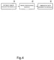
- the CPU 20A executes the dimension measurement program to realize function modules shown in a block diagram of Fig. 4 .
- the function modules to be realized by the dimension measurement program include a distance image (point group data) acquisition module 30, an image processing module 40, and a dimension data generation module 50.
- the distance image acquisition module 30 acquires the point group data (may be called the XYZ coordinate image) composed of positions (XYZ coordinates) of respective pixels in the XYZ coordinate space of the distance image of the transportation object OB photographed by the camera 22.
- the image processing module 40 generates an upper surface coordinate image corresponding to a reference surface of the transportation object OB, based on the distance image (XYZ coordinate image).
- the upper surface of the transportation object OB is made to be the reference surface.
- the image processing module 40 divides the distance image into an X coordinate image, a Y coordinate image, and a Z coordinate image, and removes coordinate points not corresponding to the upper surface (reference surface) of the transportation object OB in the respective coordinate images, to detect respective upper surface coordinate images corresponding to the upper surface (refer to Fig. 5 ).
- the dimension data generation module 50 generates dimension data indicating dimensions of the length, the width, and the height (depth, width, height) of the transportation object OB, based on the upper surface coordinate images (refer to Fig. 6 ).
- the memory 20B stores various data associated with the execution of various processings, in addition to the respective control programs to be executed by the CPU 20A.
- the storage device 20C is a nonvolatile storage medium (a hard disk or the like), and stores various program and data.
- the input device 20D inputs an instruction for controlling an operation of the dimension measurement apparatus 10.
- the input device 20D includes a touch panel, a keyboard, a button and so on, for example.
- the input device 20D detects an input of an instruction to the touch panel, the keyboard, the button and so on, and outputs (notifies) the instruction to the CPU 20A.
- the input device 20D is installed (not shown) in the vicinity of the measurement table 12 shown in Fig. 1 , and accepts an instruction of photographing start (dimension measurement start) to the transportation object OB by the camera 22.
- the display 20E displays an operation state and a processing result of the dimension measurement apparatus 10 under the control of the CPU 20A.
- the display 20E is installed (not shown) in the vicinity of the measurement table 12, for example, and presents the operation state and the processing result to a home delivery agent (receptionist) working at the measurement table 12, or a customer.
- the printer 20F prints a charge and so on determined based on the measured dimensions and weight of the transportation object OB.
- the input/output interface 20G is an interface to which the camera 22 and the weight measurement device 24 are to be connected. Another external device may be connected to the input/output interface 20G.
- Fig. 5 is a block diagram for describing details of the image processing module 40.
- the image processing module 40 includes an X coordinate image processing module 40x, a Y coordinate image processing module 40y, and a Z coordinate image processing module 40z.
- the X coordinate image processing module 40x removes X coordinate points in the range not corresponding to the upper surface of the transportation object OB from the X coordinate image to generate an upper surface X coordinate image.
- the X coordinate image processing module 40x executes respective processings of an X coordinate image generation, an existence range limitation, smoothing, a Z range limitation, closing, an x range limitation, for example, to generate the upper surface X coordinate image.
- the Y coordinate image processing module 40y removes Y coordinate points in the range not corresponding to the upper surface of the transportation object OB from the Y coordinate image to generate an upper surface Y coordinate image.
- the Y coordinate image processing module 40y executes respective processings of a Y coordinate image generation, the existence range limitation, the smoothing, the Z range limitation, the closing, a y range limitation, for example, to generate the upper surface Y coordinate image.
- the Z coordinate image processing module 40z removes Z coordinate points in the range not corresponding to the upper surface of the transportation object OB from the Z coordinate image to generate an upper surface Z coordinate image.
- the Z coordinate image processing module 40z executes respective processings of a Z coordinate image generation, the existence range limitation, the smoothing, the Z range limitation, the closing, a narrow region exclusion, for example, to generate the upper surface Z coordinate image.
- Each of the X coordinate image processing module 40x, the Y coordinate image processing module 40y, and the Z coordinate image processing module 40z limits the object to be processed to a range to be measured in the distance image generated by the camera 22 (corresponds to a range of the measurement area 18, for example), by the processing of the existence range limitation. Since each of the X coordinate image processing module 40x, the Y coordinate image processing module 40y, and the Z coordinate image processing module 40z makes, not the three-dimensional coordinate data, but only the coordinate data of the corresponding coordinate system, to be the object to be processed, the processing procedure is simplified and thereby the processing efficiency can be improved.
- Fig. 7 is a diagram showing a position relation of the camera 22 and the transportation object OB in the present embodiment.
- the camera 22 is arranged immediately above the measurement area 18 in which the transportation object OB is to be placed, for example, and photographs the transportation object OB.
- a photographable range (an angle of view) by the camera 22 is made to be an area AR1
- the range to be measured is made to be an area AR2.
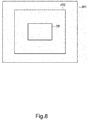
- Fig. 8 shows the areas AR1, AR2 and an example of an arrangement of the transportation object OB.
- Fig. 8 when photographing is performed by the camera 22, a range including the area AR1 is photographed.
- Each of the X coordinate image processing module 40x, the Y coordinate image processing module 40y and the Z coordinate image processing module 40z limits the object to be processed to a range included in the area AR2 shown in Fig. 8 , by the relevant processing of the existence range limitation.
- the transportation object OB is photographed in the state to be placed in the measurement area 18, the upper surface of the transportation object OB is included in the area AR2.
- each of the X coordinate image processing module 40x, the Y coordinate image processing module 40y and the Z coordinate image processing module 40z limits only coordinate values of pixels having the Z coordinate values in the range capable of corresponding to the transportation object OB, as the object to be processed, by the relevant processing of the Z range limitation. For example, in the dimension measurement apparatus 10, a coordinate value of a pixel having a Z coordinate value exceeding an upper limit of the transportation object OB whose dimension is to be measured is removed as being outside the object to be processed.
- Fig. 9 is a diagram showing the distance image (XYZ coordinate image (dot group data)) generated when the camera 22 has photographed the transportation object OB in the XYZ coordinate space (three-dimensional space).
- setting of the origin position and definition of positive directions of the coordinate system in the XYZ coordinate space shown in Fig. 9 are examples, and other setting and definition may be used.
- the origin position may be set to a part of the XYZ coordinate image
- the positive direction of the Z coordinate system may be defined to be a downward direction.
- the X coordinate image processing module 40x, the Y coordinate image processing module 40y, and the Z coordinate image processing module 40z respectively perform the processings of the Z range limitation to the X coordinate image, the Y coordinate image, and the Z coordinate image corresponding to the XYZ coordinate image shown in Fig. 9 .
- a coordinate value of a pixel having a Z coordinate value that is made to be outside the object to be processed is removed as being outside the object to be processed.
- each of the X coordinate image processing module 40x, the Y coordinate image processing module 40y, and the Z coordinate image processing module 40z removes a trash portion in the image, such as an isolated point and a thin line in the relevant coordinate image by the closing processing.
- the X coordinate image processing module 40x executes the closing processing to the X coordinate image shown in Fig. 10 to remove isolation point data P appearing as noise, for example, which does not correspond to the upper surface of the transportation object OB.
- the X coordinate image processing module 40x limits the object to be processed to the data of the X coordinate in a range corresponding to the upper surface of the transportation object OB, by the processing of the x range limitation.
- the Y coordinate image processing module 40y limits the object to be processed to the data of the Y coordinate in a range corresponding to the upper surface of the transportation object OB, by the processing of the y range limitation.
- the Z coordinate image processing module 40z when the Z coordinate data group (point group data) indicating a narrow region (narrow region) that is made not to correspond to a predetermined upper surface of the transportation object OB is present, removes the relevant coordinate data by the processing of the narrow region exclusion.
- the image processing module 40 in the present embodiment regarding the pixel position the coordinate point of which has been removed as being not corresponding to the upper surface in any one module of the X coordinate image processing module 40x, the Y coordinate image processing module 40y, and the Z coordinate image processing module 40z, makes the other coordinate image processing modules operate so as not to make the pixel position an object of the processing to remove the coordinate point.
- the pixel position which has been removed by the processing based on the Z coordinate image by the Z coordinate image processing module 40z is made outside the object to be processed in the X coordinate image processing module 40x and the Y coordinate image processing module 40y, as the relevant pixel position has to be removed also in the X coordinate image and the Y coordinate image.
- the image processing module 40 can discriminate the relevant pixel as being the object to be removed. By this means, it is possible to reduce the whole processing load in the image processing module 40.
- the processings in the X coordinate image processing module 40x, the Y coordinate image processing module 40y, and the Z coordinate image processing module 40z are respectively executed is not particularly limited.
- the processings in the X coordinate image processing module 40x, the Y coordinate image processing module 40y, and the Z coordinate image processing module 40z may be executed in series, and after the processing in the Z coordinate image processing module 40z has been executed, the processing of the X coordinate image processing module 40x and the processing of the Y coordinate image processing module 40y may be executed in parallel.
- the processings using the result may be executed in parallel in the next image processing modules in a pipeline manner.
- Fig. 6 is a block diagram for describing details of the dimension data generation module 50.
- the dimension data generation module 50 has a 3D modeling module 51, a minimum inclusion rectangular solid determination module 52, a width determination module 53, a depth determination module 54, a histogram distribution generation module 56, and a distance determination module 57.
- the 3D modeling module 51 generates an upper surface 3D model indicating the upper surface of the transportation object OB, based on the upper surface X coordinate image, the upper surface Y coordinate image, and the upper surface Z coordinate image to be obtained by the processing of the image processing module 40.
- the minimum inclusion rectangular solid determination module 52 discriminates a rectangular solid having the upper surface which the upper surface 3D model shows, that is, a rectangular solid indicating the upper surface of the transportation object OB photographed by the camera 22, based on the upper surface 3D model.
- Fig. 11 is a diagram conceptually showing the rectangular solid having the upper surface which the upper surface 3D model shows.
- the transportation object OB is not actually a complete rectangular solid, but may be deformed, for example, the side surface or the upper surface may be expanded by a matter packed in the box, or may be dented by a weight applied from outside.
- an appendage is attached to the transportation object OB, for example, packing paper, an invoice, a seal or the like may be pasted, or a string for packaging may be wound.
- a rectangular solid expressing the transportation object OB is discriminated based on the upper surface 3D model.
- the width determination module 53 determines a width (W) of the rectangular solid discriminated by the minimum inclusion rectangular solid determination module 52, that is, a dimension of the width of the upper surface of the transportation object OB, and outputs width data (lateral dimension data).
- the depth determination module 54 determines a depth (D) of the rectangular solid discriminated by the minimum inclusion rectangular solid determination module 52, that is, a dimension of the length of the upper surface of the transportation object OB, and outputs depth data (longitudinal dimension data).
- the histogram distribution generation module 56 generates a histogram distribution indicating the number of pixels for each Z coordinate value, from the upper surface Z coordinate image obtained by the processing of the image processing module 40.
- the distance determination module 57 determines a distance from the camera 22 to a position made to be the height of the upper surface of the transportation object OB, based on the histogram distribution of the upper surface Z coordinate image generated by the histogram distribution generation module 56, and determines a dimension of the height of the transportation object OB from the distance, and outputs height data.
- the distance determination module 57 determines a distance from the camera 22 to the position made to be the height of the upper surface of the transportation object OB, based on a maximum value (MaxPZ) of a peak zone of the histogram distribution of the upper surface Z coordinate image, a minimum value (MinPZ) of the peak zone of the histogram distribution of the upper surface Z coordinate image, and previously stored distance data indicating a distance from the camera 22 to the bottom surface of the transportation object OB (the upper surface of the measurement area 18).
- MaxPZ maximum value
- MinPZ minimum value
- Fig. 12 is a diagram showing the maximum value (MaxPZ) and the minimum value (MinPZ) of the peak zone of the histogram distribution of the upper surface Z coordinate image.
- the upper surface of the transportation object OB is not a plane due to an expansion, a dent, an appendage or the like as described above, but as shown in Fig. 12 , pixels of distances included in a limited range concentrate.
- the distance determination module 57 determines a median, for example, to be the distance from the camera 22 to the upper surface of the transportation object OB, based on the maximum value and the minimum value of the peak zone corresponding to the limited range.
- the distance determination module 57 subtracts the distance determined based on the histogram distribution from a predetermined distance BZ from the camera 22 to the measurement area 18 (the placing surface of the transportation object OB) to calculate a distance corresponding to the height of the transportation object OB.
- the distance determination module 57 outputs height data in accordance with the distance corresponding to a height (H) of the transportation object OB.
- a dimension measurement and a weight measurement of the transportation object OB are performed using the dimension measurement apparatus 10.
- the transportation object OB is placed inside the measurement area 18 which is provided on the upper surface of the measurement table 12.
- a dimension measurement start is instructed by an operation to the input device 20D, the processing device 20 instructs the camera 22 to photograph the transportation object OB, and instructs the weight measurement device 24 to execute the weight measurement.
- the processing device 20 inputs the distance image (dot group data) generated by the camera 22, and in the image processing module 40, divides the distance image into the X coordinate image, the Y coordinate image, and the Z coordinate image, removes coordinate points not corresponding to the upper surface (reference surface) of the transportation object OB in the respective divided coordinate images, and thereby executes the processing to detect the respective upper surface coordinate images corresponding to the upper surface.
- the dimension data generation module 50 outputs the width data (lateral dimension data), the depth data (longitudinal dimension data), and the height data, as described above, by the processing based on the result of image processing by the image processing module 40.
- the processing device 20 calculates a transportation charge, based on a sum of the dimensions of the length, the width, and the height of the transportation object OB which the data outputted by the dimension data generation module 50 indicates, the weight of the transportation object OB which the weight data to be inputted from the weight measurement device 24 indicates, a delivery destination (transportation distance) which is separately inputted through the input device 20D and so on, and a transportation mode (service contents).
- the calculated transportation charge is printed on a prescribed position of an invoice by the printer 20F, for example.
- the dimension measurement and the weight measurement are concurrently performed to the transportation object OB placed in the measurement area 18 in this manner, a working load for determining the transportation charge can be reduced.
- the shape of the transportation object OB is specified and the dimension of the transportation object OB is measured, by only the distance image obtained by photographing the upper surface of the transportation object OB, and accordingly, the dimension can be measured simply and with high accuracy, without photographing the transportation object OB for a plural number of times while changing a position and an angle.
- the distance image of the upper surface is divided into the X coordinate image, the Y coordinate image, and the Z coordinate image, and the processings are individually performed to the respective divided coordinate images, and thereby the processing load of the dimension measurement based on the distance image can be reduced. Accordingly, since an arithmetic unit with a high processing performance is not necessitated, increase in cost of the dimension measurement apparatus 10 can be avoided.
- the camera 22 is provided at a position immediately above the measurement area 18, but since at least the upper surface (reference surface) of the transportation object OB can only be photographed by the camera 22, the upper surface of the transportation object OB may be photographed obliquely from above, for example.
- the camera 22 is installed above the measurement area 18, and thereby the distance image using the upper surface of the transportation object OB (the object to be measured) as the reference surface is acquired, but the transportation object OB is photographed from the lateral direction or from the downward direction of the transportation object OB, and thereby the distance image using the side surface or the bottom surface as the reference surface may be acquired.
- the camera 22 is installed at a position where the side surface or the bottom surface of the transportation object OB becomes photographable, and the transportation object OB is photographed from the lateral direction or the downward direction.
- the transportation object OB when the transportation object OB is photographed from the lateral direction, the transportation object OB is placed in the measurement area 18, while a side surface opposite to a surface of the transportation object OB to be photographed is matched to a reference position (a wall formed vertically on the measurement area 18, for example).
- data indicating a distance from the camera 22 to the reference position (data corresponding to the above-described distance data BZ from the camera 22 to the bottom surface) is to be previously stored in the same manner as the above-described case in which the measurement area 18 is installed on the measurement table 12.
- the dimension data of the transportation object OB is generated based on the distance image of one reference surface which has been acquired by photographing the transportation object OB from one direction, but the dimension data may be generated based on the distance images of a plurality of the reference surfaces photographed from a plurality of directions (the distance images obtained by photographing the upper surface and the side surface of the transportation object OB, for example).
- an average value of the dimension data generated based on the respective distance images may be made to be final dimension data, or any effective dimension data may be selected. By this means, it becomes possible to generate the dimension data with higher accuracy.
Abstract
Description
- Embodiments described herein relate generally to a dimension measurement apparatus and a control method of the same.
- At the time of accepting a transportation object in a home delivery business or the like, a work is performed in which a weight of the transportation object is measured by a scale, dimensions of a length, a width and a height of the transportation object are respectively measured by a tape measure or the like, and a transportation charge is determined based on the combination of the measured weight and dimensions. For the reason, a home delivery agent has to separately perform the dimension measurement and the weight measurement to the transportation object, and thereby there was a problem that the working efficiency is not good.
- In contrast, an apparatus which photographs a transportation object using a distance image sensor (camera) to acquire a distance image, and measures dimensions of the transportation object based on the acquired distance image is thought of. It is possible to reduce a work to manually measure dimensions and a weight of the transportation object by using the apparatus like this.
- On the other hand, it is necessary to complete the measurement quickly and accurately at the time of measuring dimensions of a transportation object at a transportation object acceptance site. However, in order to enable the quick and accurate measurement, an arithmetic unit with high processing performance is necessitated for the dimension measurement based on the distance image, and thereby an installation cost might be increased. Accordingly, it is desired to reduce a processing load for the dimension measurement based on the distance image so that the measurement can be completed quickly and accurately without increasing the installation cost.
- To solve the above-cited problems, there is provided a dimension measurement apparatus, comprising:
- a camera which photographs an object to be measured to generate a distance image of the object to be measured; and
- a processing device which generates dimension data indicating a length, a width, and a height of the object to be measured, based on the distance image generated by the camera;
- the processing device having a memory to store a control program for generating the dimension data and a controller;
- the controller executing the control program,
- to acquire the distance image of the object to be measured,
- to divide the acquired distance image into an X coordinate image, a Y coordinate image, and a Z coordinate image in a three-dimensional space,
- to remove a coordinate point not corresponding to one reference surface of the object to be measured, in the respective divided X coordinate image, Y coordinate image, and Z coordinate image, to detect an X coordinate image, a Y coordinate image, and a Z coordinate image of the reference surface, and
- to generate the dimension data indicating the length, the width, and the height of the object to be measured, based on the respective detected coordinate images of the reference surface.
- Preferably, the controller may perform an X coordinate image processing which removes an X coordinate point in a range not corresponding to the reference surface from the divided X coordinate image, to generate the X coordinate image of the reference surface;
- the controller may perform a Y coordinate image processing which removes a Y coordinate point in a range not corresponding to the reference surface from the divided Y coordinate image, to generate the Y coordinate image of the reference surface; and
- the controller may perform a Z coordinate image processing which removes a Z coordinate point in a range not corresponding to the reference surface from the divided Z coordinate image, to generate the Z coordinate image of the reference surface.
- Preferably, regarding a pixel position a coordinate point of which has been removed in any one of the X coordinate image processing, the Y coordinate image processing, and the Z coordinate image processing, the controller may not make the pixel position an object of a processing to remove the coordinate point, but may perform the other coordinate image processing.
- Preferably, the controller may generate the dimension data indicating the height of the object to be measured, based on a histogram of a Z coordinate value based on the Z coordinate image of the reference surface.
- Preferably the dimension measurement apparatus may further comprise:
- a weight measurement device which measures a weight of the object to be measured to generate weight data;
- wherein the controller may input the weight data of the object to be measured which has been generated by the weight measurement device, and calculate a transportation charge of the object to be measured, based on the dimension data and the weight data of the object to be measured.
- In another exemplary embodiment, there is also provided a control method of a dimension measurement apparatus having a camera which photographs an object to be measured to generate a distance image of the object to be measured, comprising:
- acquiring the distance image of the object to be measured which has been generated by the camera;
- dividing the acquired distance image into an X coordinate image, a Y coordinate image, and a Z coordinate image in a three-dimensional space;
- removing a coordinate point not corresponding to one reference surface of the object to be measured, in the respective divided X coordinate image, Y coordinate image, and Z coordinate image, to detect an X coordinate image, a Y coordinate image, and a Z coordinate image of the reference surface; and
- generating dimension data indicating a length, a width, and a height of the object to be measured, based on the respective detected coordinate images of the reference surface.
- Preferably, the detection of the X coordinate image of the reference surface may include to perform an X coordinate image processing which removes an X coordinate point in a range not corresponding to the reference surface from the divided X coordinate image, to generate the X coordinate image of the reference surface;
- the detection of the Y coordinate image of the reference surface may include to perform a Y coordinate image processing which removes a Y coordinate point in a range not corresponding to the reference surface from the divided Y coordinate image, to generate the Y coordinate image of the reference surface; and
- the detection of the Z coordinate image of the reference surface may include to perform a Z coordinate image processing which removes a Z coordinate point in a range not corresponding to the reference surface from the divided Z coordinate image, to generate the Z coordinate image of the reference surface.
- Preferably, the detection of each of the coordinate images of the reference surface may include, regarding a pixel position a coordinate point of which has been removed in any one of the X coordinate image processing, the Y coordinate image processing, and the Z coordinate image processing, not to make the pixel position an object of a processing to remove the coordinate point, but to perform the other coordinate image processing.
- Preferably, the generation of the dimension data may include to generate the dimension data indicating the height of the object to be measured, based on a histogram of a Z coordinate value based on the Z coordinate image of the reference surface.
- The control method of a dimension measurement apparatus may further comprise:
- inputting weight data of the object to be measured which has been generated by a weight measurement device to measure a weight of the object to be measured; and
- calculating a transportation charge of the object to be measured, based on the dimension data and the weight data of the object to be measured.
- The above and other objects, features and advantages of the present invention will be made apparent from the following description of the preferred embodiments, given as nonlimiting examples, with reference to the accompanying drawings, in which:
-
Fig. 1 is a diagram showing an outer appearance of a dimension measurement apparatus according to an embodiment. -
Fig. 2 is a block diagram showing a configuration of the dimension measurement apparatus according to the embodiment. -
Fig. 3 is a block diagram showing a configuration of the processing device according to the embodiment. -
Fig. 4 is a block diagram showing function modules to be realized by a dimension measurement program according to the embodiment. -
Fig. 5 is a block diagram for describing the image processing module according to the embodiment. -
Fig. 6 is a block diagram for describing the dimension data generation module according to the embodiment. -
Fig. 7 is a diagram showing a position relation of the camera and the transportation object according to the embodiment. -
Fig. 8 is a diagram showing a photographable range of the camera according to the embodiment. -
Fig. 9 is a diagram in which the distance image according to the embodiment obtained by photographing the transportation object by the camera is expressed in an XYZ coordinate space. -
Fig. 10 is a diagram for describing the closing processing according to the embodiment. -
Fig. 11 is a diagram conceptually showing a rectangular solid having an upper surface which anupper surface 3D model indicates, based on theupper surface 3D model which the 3D modeling module according to the embodiment has generated. -
Fig. 12 is a diagram showing a maximum value and a minimum value of a peak zone of a histogram distribution of the upper surface Z coordinate image which the histogram distribution generation module according to the embodiment has generated. - According to one embodiment, a dimension measurement apparatus has a camera and a processing device. The camera photographs an object to be measured to generate a distance image of the object to be measured. The processing device has a memory and a controller so that the processing device generates dimension data indicating a length, a width, and a height of the object to be measured based on the distance image generated by the camera. The memory stores a control program for generating the dimension data. The controller acquires the distance image of the object to be measured. The controller divides the acquired distance image into an X coordinate image, a Y coordinate image, and a Z coordinate image in a three-dimensional space. The controller removes a coordinate point not corresponding to one reference surface of the object to be measured, in the respective divided X coordinate image, Y coordinate image, and Z coordinate image, to detect an X coordinate image, a Y coordinate image, and a Z coordinate image of the reference surface. Further, the controller generates the dimension data indicating the length, the width, and the height of the object to be measured, based on the respective detected coordinate images of the reference surface.
- Hereinafter, the present embodiment will be described with reference to the drawings. In the drawings, the same symbols indicate the same or the similar portions.
Fig. 1 is a diagram showing an outer appearance of adimension measurement apparatus 10 according to the present embodiment.Fig. 2 is a block diagram showing a configuration of thedimension measurement apparatus 10 according to the present embodiment. - The
dimension measurement apparatus 10 is installed and used at an acceptance place of a transportation object OB of a home delivery agent, for example. Thedimension measurement apparatus 10 measures dimensions of a length, a width, and a height (a depth, a width, and a height), and a weight of the transportation object OB, in order to determine a transportation charge of the transportation object OB. - As shown in
Fig. 1 andFig. 2 , thedimension measurement apparatus 10 has a measurement table 12, acamera 22, aweight measurement device 24, and aprocessing device 20. Ameasurement area 18 in which the transportation object OB that is an object to be measured is to be horizontally placed, for example, is provided on an upper surface of the measurement table 12. Thecamera 22 supported by asupport member 14 is arranged above themeasurement area 18. Thecamera 22 photographs the transportation object OB placed in themeasurement area 18 from above to generate a distance image. The distance image is used in a processing to measure dimensions of the length, the width, and the height of the transportation object OB. The distance image is an image including values by which respective pixels of the image obtained by imaging the photographic subject indicate distances to the photographic subject. - The distance image generated by the
camera 22 is expressed by point group data (XYZ coordinate image) including positions (XYZ coordinates) of respective pixels in an XYZ coordinate space. The XYZ coordinate space is defined by an orthogonal coordinate system using, as a reference, an origin which is set to any position within a space to be photographed by thecamera 22, for example. InFig. 1 , the origin is defined to a position corresponding to one corner position of therectangular measurement area 18, for example. An X coordinate axis and a Y coordinate axis are defined along sides of themeasurement area 18. A Z coordinate axis is defined to an upward direction from the placing surface of themeasurement area 18 on which the transportation object OB is to be placed. In the present embodiment, description will be made assuming that the length (depth), the width (width), and the height of the transportation object OB correspond respectively to the Y coordinate axis direction, the X coordinate axis direction, and the Z coordinate axis direction in the XYZ coordinate space. - The
camera 22 may be a stereo camera to output a distance image based on parallax of the imaged images by two cameras, for example, or may be a distance image camera (sensor) of a TOF (Time Of Flight) system to measure a distance from a time required for a projected laser to reciprocate to a photographic subject. In addition, thecamera 22 may be a camera to generate a distance image of another system. - In addition, the
weight measurement device 24 is provided in themeasurement area 18. Theweight measurement device 24 measures a weight of the transportation object OB placed in themeasurement area 18. - The
processing device 20 inputs (acquires) the distance image (point group data) generated by thecamera 22. Theprocessing device 20 executes a dimension processing to generate dimension data indicating dimensions of the length, the width, and the height of the transportation object OB. In addition, theprocessing device 20 inputs the weight data measured by theweight measurement device 24. Theprocessing device 20 executes a processing to calculate a transportation charge of the transportation object OB, using the inputted weight data and the generated dimension data. -
Fig. 3 is a block diagram showing theprocessing device 20 according to the present embodiment. Theprocessing device 20 has a function of a computer. Specifically, theprocessing device 20 has acontroller 20A, amemory 20B, astorage device 20C, aninput device 20D, adisplay 20E, aprinter 20F, and an input/output interface 20G. - The
controller 20A is a CPU (Central Processing Unit), for example. Hereinafter, thecontroller 20A may be called theCPU 20A. TheCPU 20A executes a control program to control the whole of thedimension measurement apparatus 10. The control program includes a dimension measurement program and so on. TheCPU 20A executes the dimension measurement program to realize function modules shown in a block diagram ofFig. 4 . The function modules to be realized by the dimension measurement program include a distance image (point group data)acquisition module 30, animage processing module 40, and a dimensiondata generation module 50. - The distance
image acquisition module 30 acquires the point group data (may be called the XYZ coordinate image) composed of positions (XYZ coordinates) of respective pixels in the XYZ coordinate space of the distance image of the transportation object OB photographed by thecamera 22. Theimage processing module 40 generates an upper surface coordinate image corresponding to a reference surface of the transportation object OB, based on the distance image (XYZ coordinate image). In the present embodiment, the upper surface of the transportation object OB is made to be the reference surface. Theimage processing module 40 divides the distance image into an X coordinate image, a Y coordinate image, and a Z coordinate image, and removes coordinate points not corresponding to the upper surface (reference surface) of the transportation object OB in the respective coordinate images, to detect respective upper surface coordinate images corresponding to the upper surface (refer toFig. 5 ). The dimensiondata generation module 50 generates dimension data indicating dimensions of the length, the width, and the height (depth, width, height) of the transportation object OB, based on the upper surface coordinate images (refer toFig. 6 ). - The
memory 20B stores various data associated with the execution of various processings, in addition to the respective control programs to be executed by theCPU 20A. Thestorage device 20C is a nonvolatile storage medium (a hard disk or the like), and stores various program and data. - The
input device 20D inputs an instruction for controlling an operation of thedimension measurement apparatus 10. Theinput device 20D includes a touch panel, a keyboard, a button and so on, for example. Theinput device 20D detects an input of an instruction to the touch panel, the keyboard, the button and so on, and outputs (notifies) the instruction to theCPU 20A. For example, theinput device 20D is installed (not shown) in the vicinity of the measurement table 12 shown inFig. 1 , and accepts an instruction of photographing start (dimension measurement start) to the transportation object OB by thecamera 22. - The
display 20E displays an operation state and a processing result of thedimension measurement apparatus 10 under the control of theCPU 20A. Thedisplay 20E is installed (not shown) in the vicinity of the measurement table 12, for example, and presents the operation state and the processing result to a home delivery agent (receptionist) working at the measurement table 12, or a customer. Theprinter 20F prints a charge and so on determined based on the measured dimensions and weight of the transportation object OB. - The input/
output interface 20G is an interface to which thecamera 22 and theweight measurement device 24 are to be connected. Another external device may be connected to the input/output interface 20G. -
Fig. 5 is a block diagram for describing details of theimage processing module 40. As shown inFig. 5 , theimage processing module 40 includes an X coordinateimage processing module 40x, a Y coordinateimage processing module 40y, and a Z coordinateimage processing module 40z. - The X coordinate
image processing module 40x removes X coordinate points in the range not corresponding to the upper surface of the transportation object OB from the X coordinate image to generate an upper surface X coordinate image. The X coordinateimage processing module 40x executes respective processings of an X coordinate image generation, an existence range limitation, smoothing, a Z range limitation, closing, an x range limitation, for example, to generate the upper surface X coordinate image. - The Y coordinate
image processing module 40y removes Y coordinate points in the range not corresponding to the upper surface of the transportation object OB from the Y coordinate image to generate an upper surface Y coordinate image. The Y coordinateimage processing module 40y executes respective processings of a Y coordinate image generation, the existence range limitation, the smoothing, the Z range limitation, the closing, a y range limitation, for example, to generate the upper surface Y coordinate image. - The Z coordinate
image processing module 40z removes Z coordinate points in the range not corresponding to the upper surface of the transportation object OB from the Z coordinate image to generate an upper surface Z coordinate image. The Z coordinateimage processing module 40z executes respective processings of a Z coordinate image generation, the existence range limitation, the smoothing, the Z range limitation, the closing, a narrow region exclusion, for example, to generate the upper surface Z coordinate image. - Each of the X coordinate
image processing module 40x, the Y coordinateimage processing module 40y, and the Z coordinateimage processing module 40z limits the object to be processed to a range to be measured in the distance image generated by the camera 22 (corresponds to a range of themeasurement area 18, for example), by the processing of the existence range limitation. Since each of the X coordinateimage processing module 40x, the Y coordinateimage processing module 40y, and the Z coordinateimage processing module 40z makes, not the three-dimensional coordinate data, but only the coordinate data of the corresponding coordinate system, to be the object to be processed, the processing procedure is simplified and thereby the processing efficiency can be improved. -
Fig. 7 is a diagram showing a position relation of thecamera 22 and the transportation object OB in the present embodiment. As shown inFig. 7 , thecamera 22 is arranged immediately above themeasurement area 18 in which the transportation object OB is to be placed, for example, and photographs the transportation object OB. For example, a photographable range (an angle of view) by thecamera 22 is made to be an area AR1, and the range to be measured (the measurement area 18) is made to be an area AR2. -
Fig. 8 shows the areas AR1, AR2 and an example of an arrangement of the transportation object OB. As shown inFig. 8 , when photographing is performed by thecamera 22, a range including the area AR1 is photographed. Each of the X coordinateimage processing module 40x, the Y coordinateimage processing module 40y and the Z coordinateimage processing module 40z limits the object to be processed to a range included in the area AR2 shown inFig. 8 , by the relevant processing of the existence range limitation. As shown inFig. 8 , when the transportation object OB is photographed in the state to be placed in themeasurement area 18, the upper surface of the transportation object OB is included in the area AR2. - In addition, each of the X coordinate
image processing module 40x, the Y coordinateimage processing module 40y and the Z coordinateimage processing module 40z limits only coordinate values of pixels having the Z coordinate values in the range capable of corresponding to the transportation object OB, as the object to be processed, by the relevant processing of the Z range limitation. For example, in thedimension measurement apparatus 10, a coordinate value of a pixel having a Z coordinate value exceeding an upper limit of the transportation object OB whose dimension is to be measured is removed as being outside the object to be processed. -
Fig. 9 is a diagram showing the distance image (XYZ coordinate image (dot group data)) generated when thecamera 22 has photographed the transportation object OB in the XYZ coordinate space (three-dimensional space). In addition, setting of the origin position and definition of positive directions of the coordinate system in the XYZ coordinate space shown inFig. 9 are examples, and other setting and definition may be used. For example, the origin position may be set to a part of the XYZ coordinate image, and the positive direction of the Z coordinate system may be defined to be a downward direction. - The X coordinate
image processing module 40x, the Y coordinateimage processing module 40y, and the Z coordinateimage processing module 40z respectively perform the processings of the Z range limitation to the X coordinate image, the Y coordinate image, and the Z coordinate image corresponding to the XYZ coordinate image shown inFig. 9 . By this means, a coordinate value of a pixel having a Z coordinate value that is made to be outside the object to be processed is removed as being outside the object to be processed. - In addition, each of the X coordinate
image processing module 40x, the Y coordinateimage processing module 40y, and the Z coordinateimage processing module 40z removes a trash portion in the image, such as an isolated point and a thin line in the relevant coordinate image by the closing processing. - For example, the X coordinate
image processing module 40x executes the closing processing to the X coordinate image shown inFig. 10 to remove isolation point data P appearing as noise, for example, which does not correspond to the upper surface of the transportation object OB. - The X coordinate
image processing module 40x limits the object to be processed to the data of the X coordinate in a range corresponding to the upper surface of the transportation object OB, by the processing of the x range limitation. In addition, the Y coordinateimage processing module 40y limits the object to be processed to the data of the Y coordinate in a range corresponding to the upper surface of the transportation object OB, by the processing of the y range limitation. The Z coordinateimage processing module 40z, when the Z coordinate data group (point group data) indicating a narrow region (narrow region) that is made not to correspond to a predetermined upper surface of the transportation object OB is present, removes the relevant coordinate data by the processing of the narrow region exclusion. - The
image processing module 40 in the present embodiment, regarding the pixel position the coordinate point of which has been removed as being not corresponding to the upper surface in any one module of the X coordinateimage processing module 40x, the Y coordinateimage processing module 40y, and the Z coordinateimage processing module 40z, makes the other coordinate image processing modules operate so as not to make the pixel position an object of the processing to remove the coordinate point. For example, the pixel position which has been removed by the processing based on the Z coordinate image by the Z coordinateimage processing module 40z is made outside the object to be processed in the X coordinateimage processing module 40x and the Y coordinateimage processing module 40y, as the relevant pixel position has to be removed also in the X coordinate image and the Y coordinate image. When a coordinate value of one pixel is expressed by the XYZ coordinate, if the pixel is not discriminated as being the object to be removed in each of the X coordinate, the Y coordinate and the Z coordinate, the pixel cannot be discriminated as being the object to be removed. However, at a time point when the pixel is discriminated as being the object to be removed in any of the X coordinate, the Y coordinate and the Z coordinate, theimage processing module 40 can discriminate the relevant pixel as being the object to be removed. By this means, it is possible to reduce the whole processing load in theimage processing module 40. - In addition, at what timings the processings in the X coordinate
image processing module 40x, the Y coordinateimage processing module 40y, and the Z coordinateimage processing module 40z are respectively executed is not particularly limited. For example, the processings in the X coordinateimage processing module 40x, the Y coordinateimage processing module 40y, and the Z coordinateimage processing module 40z may be executed in series, and after the processing in the Z coordinateimage processing module 40z has been executed, the processing of the X coordinateimage processing module 40x and the processing of the Y coordinateimage processing module 40y may be executed in parallel. In addition, when any image processing module finishes a processing in a certain stage, the processings using the result may be executed in parallel in the next image processing modules in a pipeline manner. -
Fig. 6 is a block diagram for describing details of the dimensiondata generation module 50. As shown inFig. 6 , the dimensiondata generation module 50 has a3D modeling module 51, a minimum inclusion rectangularsolid determination module 52, awidth determination module 53, adepth determination module 54, a histogramdistribution generation module 56, and adistance determination module 57. - The
3D modeling module 51 generates anupper surface 3D model indicating the upper surface of the transportation object OB, based on the upper surface X coordinate image, the upper surface Y coordinate image, and the upper surface Z coordinate image to be obtained by the processing of theimage processing module 40. The minimum inclusion rectangularsolid determination module 52 discriminates a rectangular solid having the upper surface which theupper surface 3D model shows, that is, a rectangular solid indicating the upper surface of the transportation object OB photographed by thecamera 22, based on theupper surface 3D model. -
Fig. 11 is a diagram conceptually showing the rectangular solid having the upper surface which theupper surface 3D model shows. The transportation object OB is not actually a complete rectangular solid, but may be deformed, for example, the side surface or the upper surface may be expanded by a matter packed in the box, or may be dented by a weight applied from outside. In addition, there may be also a case in which an appendage is attached to the transportation object OB, for example, packing paper, an invoice, a seal or the like may be pasted, or a string for packaging may be wound. In the present embodiment, assuming that the transportation object OB in this state has a shape (an approximately rectangular solid) corresponding to a rectangular solid, a rectangular solid expressing the transportation object OB is discriminated based on theupper surface 3D model. Thewidth determination module 53 determines a width (W) of the rectangular solid discriminated by the minimum inclusion rectangularsolid determination module 52, that is, a dimension of the width of the upper surface of the transportation object OB, and outputs width data (lateral dimension data). Thedepth determination module 54 determines a depth (D) of the rectangular solid discriminated by the minimum inclusion rectangularsolid determination module 52, that is, a dimension of the length of the upper surface of the transportation object OB, and outputs depth data (longitudinal dimension data). - The histogram
distribution generation module 56 generates a histogram distribution indicating the number of pixels for each Z coordinate value, from the upper surface Z coordinate image obtained by the processing of theimage processing module 40. - The
distance determination module 57 determines a distance from thecamera 22 to a position made to be the height of the upper surface of the transportation object OB, based on the histogram distribution of the upper surface Z coordinate image generated by the histogramdistribution generation module 56, and determines a dimension of the height of the transportation object OB from the distance, and outputs height data. Thedistance determination module 57 determines a distance from thecamera 22 to the position made to be the height of the upper surface of the transportation object OB, based on a maximum value (MaxPZ) of a peak zone of the histogram distribution of the upper surface Z coordinate image, a minimum value (MinPZ) of the peak zone of the histogram distribution of the upper surface Z coordinate image, and previously stored distance data indicating a distance from thecamera 22 to the bottom surface of the transportation object OB (the upper surface of the measurement area 18). -
Fig. 12 is a diagram showing the maximum value (MaxPZ) and the minimum value (MinPZ) of the peak zone of the histogram distribution of the upper surface Z coordinate image. - The upper surface of the transportation object OB is not a plane due to an expansion, a dent, an appendage or the like as described above, but as shown in
Fig. 12 , pixels of distances included in a limited range concentrate. Thedistance determination module 57 determines a median, for example, to be the distance from thecamera 22 to the upper surface of the transportation object OB, based on the maximum value and the minimum value of the peak zone corresponding to the limited range. Thedistance determination module 57 subtracts the distance determined based on the histogram distribution from a predetermined distance BZ from thecamera 22 to the measurement area 18 (the placing surface of the transportation object OB) to calculate a distance corresponding to the height of the transportation object OB. Thedistance determination module 57 outputs height data in accordance with the distance corresponding to a height (H) of the transportation object OB. - Next, an operation of the
dimension measurement apparatus 10 in the present embodiment will be described. For example, in order to determine a transportation charge of the transportation object OB, a dimension measurement and a weight measurement of the transportation object OB are performed using thedimension measurement apparatus 10. The transportation object OB is placed inside themeasurement area 18 which is provided on the upper surface of the measurement table 12. Here, a dimension measurement start is instructed by an operation to theinput device 20D, theprocessing device 20 instructs thecamera 22 to photograph the transportation object OB, and instructs theweight measurement device 24 to execute the weight measurement. - The
processing device 20 inputs the distance image (dot group data) generated by thecamera 22, and in theimage processing module 40, divides the distance image into the X coordinate image, the Y coordinate image, and the Z coordinate image, removes coordinate points not corresponding to the upper surface (reference surface) of the transportation object OB in the respective divided coordinate images, and thereby executes the processing to detect the respective upper surface coordinate images corresponding to the upper surface. The dimensiondata generation module 50 outputs the width data (lateral dimension data), the depth data (longitudinal dimension data), and the height data, as described above, by the processing based on the result of image processing by theimage processing module 40. - The
processing device 20 calculates a transportation charge, based on a sum of the dimensions of the length, the width, and the height of the transportation object OB which the data outputted by the dimensiondata generation module 50 indicates, the weight of the transportation object OB which the weight data to be inputted from theweight measurement device 24 indicates, a delivery destination (transportation distance) which is separately inputted through theinput device 20D and so on, and a transportation mode (service contents). The calculated transportation charge is printed on a prescribed position of an invoice by theprinter 20F, for example. - Since in the
dimension measurement apparatus 10 in the present embodiment, the dimension measurement and the weight measurement are concurrently performed to the transportation object OB placed in themeasurement area 18 in this manner, a working load for determining the transportation charge can be reduced. In the dimension measurement, the shape of the transportation object OB is specified and the dimension of the transportation object OB is measured, by only the distance image obtained by photographing the upper surface of the transportation object OB, and accordingly, the dimension can be measured simply and with high accuracy, without photographing the transportation object OB for a plural number of times while changing a position and an angle. - In addition, in the processing in the
processing device 20, the distance image of the upper surface is divided into the X coordinate image, the Y coordinate image, and the Z coordinate image, and the processings are individually performed to the respective divided coordinate images, and thereby the processing load of the dimension measurement based on the distance image can be reduced. Accordingly, since an arithmetic unit with a high processing performance is not necessitated, increase in cost of thedimension measurement apparatus 10 can be avoided. - In addition, in the above-described description, the
camera 22 is provided at a position immediately above themeasurement area 18, but since at least the upper surface (reference surface) of the transportation object OB can only be photographed by thecamera 22, the upper surface of the transportation object OB may be photographed obliquely from above, for example. - Further, in the above-described description, the
camera 22 is installed above themeasurement area 18, and thereby the distance image using the upper surface of the transportation object OB (the object to be measured) as the reference surface is acquired, but the transportation object OB is photographed from the lateral direction or from the downward direction of the transportation object OB, and thereby the distance image using the side surface or the bottom surface as the reference surface may be acquired. In this case, thecamera 22 is installed at a position where the side surface or the bottom surface of the transportation object OB becomes photographable, and the transportation object OB is photographed from the lateral direction or the downward direction. In addition, when the transportation object OB is photographed from the lateral direction, the transportation object OB is placed in themeasurement area 18, while a side surface opposite to a surface of the transportation object OB to be photographed is matched to a reference position (a wall formed vertically on themeasurement area 18, for example). In addition, data indicating a distance from thecamera 22 to the reference position (data corresponding to the above-described distance data BZ from thecamera 22 to the bottom surface) is to be previously stored in the same manner as the above-described case in which themeasurement area 18 is installed on the measurement table 12. Similarly, when the transportation object OB is photographed from the downward direction, data indicating a distance from thecamera 22 provided below themeasurement area 18 to the upper surface of the transportation object OB is to be previously stored (in this case, the placing surface of themeasurement area 18 is to be formed of a transparent member). - In addition, in the above-described description, the dimension data of the transportation object OB is generated based on the distance image of one reference surface which has been acquired by photographing the transportation object OB from one direction, but the dimension data may be generated based on the distance images of a plurality of the reference surfaces photographed from a plurality of directions (the distance images obtained by photographing the upper surface and the side surface of the transportation object OB, for example). For example, an average value of the dimension data generated based on the respective distance images may be made to be final dimension data, or any effective dimension data may be selected. By this means, it becomes possible to generate the dimension data with higher accuracy.
- While certain embodiments have been described, these embodiments have been presented by way of example only, and are not intended to limit the scope of the inventions. Indeed, the novel embodiments described herein may be embodied in a variety of other forms; furthermore, various omissions, substitutions and changes in the form of the embodiments described herein may be made without departing from the scope of the inventions. The accompanying claims and their equivalents are intended to cover such forms or modifications as would fall within the scope of the inventions.
Claims (10)
- A dimension measurement apparatus, comprising:a camera which photographs an object to be measured to generate a distance image of the object to be measured; anda processing device which generates dimension data indicating a length, a width, and a height of the object to be measured, based on the distance image generated by the camera;the processing device having a memory to store a control program for generating the dimension data and a controller;the controller executing the control program,to acquire the distance image of the object to be measured,to divide the acquired distance image into an X coordinate image, a Y coordinate image, and a Z coordinate image in a three-dimensional space,to remove a coordinate point not corresponding to one reference surface of the object to be measured, in the respective divided X coordinate image, Y coordinate image, and Z coordinate image, to detect an X coordinate image, a Y coordinate image, and a Z coordinate image of the reference surface, andto generate the dimension data indicating the length, the width, and the height of the object to be measured, based on the respective detected coordinate images of the reference surface.
- The dimension measurement apparatus according to Claim 1, wherein:the controller performs an X coordinate image processing which removes an X coordinate point in a range not corresponding to the reference surface from the divided X coordinate image, to generate the X coordinate image of the reference surface;the controller performs a Y coordinate image processing which removes a Y coordinate point in a range not corresponding to the reference surface from the divided Y coordinate image, to generate the Y coordinate image of the reference surface; andthe controller performs a Z coordinate image processing which removes a Z coordinate point in a range not corresponding to the reference surface from the divided Z coordinate image, to generate the Z coordinate image of the reference surface.
- The dimension measurement apparatus according to Claim 2, wherein regarding a pixel position a coordinate point of which has been removed in any one of the X coordinate image processing, the Y coordinate image processing, and the Z coordinate image processing, the controller does not make the pixel position an object of a processing to remove the coordinate point, but performs the other coordinate image processing.
- The dimension measurement apparatus according to Claim 2 or 3, wherein the controller generates the dimension data indicating the height of the object to be measured, based on a histogram of a Z coordinate value based on the Z coordinate image of the reference surface.
- The dimension measurement apparatus according to any one of Claims 1 to 4, further comprising:a weight measurement device which measures a weight of the object to be measured to generate weight data;wherein the controller inputs the weight data of the object to be measured which has been generated by the weight measurement device, and calculates a transportation charge of the object to be measured, based on the dimension data and the weight data of the object to be measured.
- A control method of a dimension measurement apparatus having a camera which photographs an object to be measured to generate a distance image of the object to be measured, comprising:acquiring the distance image of the object to be measured which has been generated by the camera;dividing the acquired distance image into an X coordinate image, a Y coordinate image, and a Z coordinate image in a three-dimensional space;removing a coordinate point not corresponding to one reference surface of the object to be measured, in the respective divided X coordinate image, Y coordinate image, and Z coordinate image, to detect an X coordinate image, a Y coordinate image, and a Z coordinate image of the reference surface; andgenerating dimension data indicating a length, a width, and a height of the object to be measured, based on the respective detected coordinate images of the reference surface.
- The control method of a dimension measurement apparatus according to Claim 6, wherein:the detection of the X coordinate image of the reference surface includes to perform an X coordinate image processing which removes an X coordinate point in a range not corresponding to the reference surface from the divided X coordinate image, to generate the X coordinate image of the reference surface;the detection of the Y coordinate image of the reference surface includes to perform a Y coordinate image processing which removes a Y coordinate point in a range not corresponding to the reference surface from the divided Y coordinate image, to generate the Y coordinate image of the reference surface; andthe detection of the Z coordinate image of the reference surface includes to perform a Z coordinate image processing which removes a Z coordinate point in a range not corresponding to the reference surface from the divided Z coordinate image, to generate the Z coordinate image of the reference surface.
- The control method of a dimension measurement apparatus according to Claim 7, wherein the detection of each of the coordinate images of the reference surface includes, regarding a pixel position a coordinate point of which has been removed in any one of the X coordinate image processing, the Y coordinate image processing, and the Z coordinate image processing, not to make the pixel position an object of a processing to remove the coordinate point, but to perform the other coordinate image processing.
- The control method of a dimension measurement apparatus according to Claim 7 or 8, wherein the generation of the dimension data includes to generate the dimension data indicating the height of the object to be measured, based on a histogram of a Z coordinate value based on the Z coordinate image of the reference surface.
- The control method of a dimension measurement apparatus according to any one of Claims 6 to 9, further comprising:inputting weight data of the object to be measured which has been generated by a weight measurement device to measure a weight of the object to be measured; andcalculating a transportation charge of the object to be measured, based on the dimension data and the weight data of the object to be measured.
Applications Claiming Priority (1)
| Application Number | Priority Date | Filing Date | Title |
|---|---|---|---|
| JP2017150754A JP6981802B2 (en) | 2017-08-03 | 2017-08-03 | Dimension measuring device |
Publications (2)
| Publication Number | Publication Date |
|---|---|
| EP3438602A1 true EP3438602A1 (en) | 2019-02-06 |
| EP3438602B1 EP3438602B1 (en) | 2022-05-11 |
Family
ID=63144855
Family Applications (1)
| Application Number | Title | Priority Date | Filing Date |
|---|---|---|---|
| EP18187182.3A Active EP3438602B1 (en) | 2017-08-03 | 2018-08-03 | Dimension measurement apparatus and control method of the same |
Country Status (3)
| Country | Link |
|---|---|
| US (1) | US20190041190A1 (en) |
| EP (1) | EP3438602B1 (en) |
| JP (1) | JP6981802B2 (en) |
Cited By (2)
| Publication number | Priority date | Publication date | Assignee | Title |
|---|---|---|---|---|
| CN110715870A (en) * | 2019-10-21 | 2020-01-21 | 张丽 | Cargo weight data cheating detection system |
| KR102352042B1 (en) * | 2020-07-30 | 2022-01-19 | 주식회사 에스티엔 | Poultry Weighing and Weight Estimation System |
Families Citing this family (4)
| Publication number | Priority date | Publication date | Assignee | Title |
|---|---|---|---|---|
| JPWO2020217651A1 (en) * | 2019-04-25 | 2020-10-29 | ||
| CN110017773B (en) * | 2019-05-09 | 2021-12-17 | 福建(泉州)哈工大工程技术研究院 | Package volume measuring method based on machine vision |
| JP6798725B1 (en) * | 2019-11-14 | 2020-12-09 | Necプラットフォームズ株式会社 | Luggage measuring device, luggage reception system, luggage measuring method, and program |
| JP7053064B2 (en) * | 2020-11-18 | 2022-04-12 | Necプラットフォームズ株式会社 | Luggage reception system and luggage reception method |
Citations (4)
| Publication number | Priority date | Publication date | Assignee | Title |
|---|---|---|---|---|
| US6614928B1 (en) * | 1999-12-21 | 2003-09-02 | Electronics And Telecommunications Research Institute | Automatic parcel volume capture system and volume capture method using parcel image recognition |
| DE102004049482A1 (en) * | 2004-10-11 | 2006-04-13 | Sick Ag | Device for monitoring moving objects |
| US20100290665A1 (en) * | 2009-05-13 | 2010-11-18 | Applied Vision Company, Llc | System and method for dimensioning objects using stereoscopic imaging |
| US20130121564A1 (en) * | 2010-07-05 | 2013-05-16 | Kabushiki Kaisha Topcon | Point cloud data processing device, point cloud data processing system, point cloud data processing method, and point cloud data processing program |
Family Cites Families (13)
| Publication number | Priority date | Publication date | Assignee | Title |
|---|---|---|---|---|
| JPH03246406A (en) * | 1990-02-26 | 1991-11-01 | Matsushita Electric Ind Co Ltd | Baggage shape measuring instrument |
| KR100422370B1 (en) * | 2000-12-27 | 2004-03-18 | 한국전자통신연구원 | An Apparatus and Method to Measuring Dimensions of 3D Object on a Moving Conveyor |
| JP3952460B2 (en) * | 2002-11-19 | 2007-08-01 | 本田技研工業株式会社 | Moving object detection apparatus, moving object detection method, and moving object detection program |
| US8140395B2 (en) * | 2007-11-26 | 2012-03-20 | Proiam, Llc | Enrollment apparatus, system, and method |
| JP2010181919A (en) * | 2009-02-03 | 2010-08-19 | Toyohashi Univ Of Technology | Three-dimensional shape specifying device, three-dimensional shape specifying method, three-dimensional shape specifying program |
| JP2013072857A (en) * | 2011-09-29 | 2013-04-22 | Dainippon Screen Mfg Co Ltd | Three-dimensional position/attitude recognition apparatus, method and program |
| JP5770763B2 (en) * | 2013-02-26 | 2015-08-26 | 株式会社サンテック | Measuring instrument |
| US9464885B2 (en) * | 2013-08-30 | 2016-10-11 | Hand Held Products, Inc. | System and method for package dimensioning |
| US10681257B2 (en) * | 2015-08-26 | 2020-06-09 | Zhejiang Dahua Technology Co., Ltd. | Methods and systems for traffic monitoring |
| WO2017110071A1 (en) * | 2015-12-25 | 2017-06-29 | パナソニックIpマネジメント株式会社 | Size measurement device, delivery box apparatus, and size measurement method |
| US9898833B1 (en) * | 2016-07-15 | 2018-02-20 | Northrop Grumman Systems Corporation | Apparatus and method for determining the dimensions of a package while in motion |
| US10089750B2 (en) * | 2017-02-02 | 2018-10-02 | Intel Corporation | Method and system of automatic object dimension measurement by using image processing |
| US10397551B2 (en) * | 2017-07-26 | 2019-08-27 | Symbol Technologies, Llc | Temperature compensation for image acquisition and processing apparatus and methods |
-
2017
- 2017-08-03 JP JP2017150754A patent/JP6981802B2/en active Active
-
2018
- 2018-07-17 US US16/037,387 patent/US20190041190A1/en not_active Abandoned
- 2018-08-03 EP EP18187182.3A patent/EP3438602B1/en active Active
Patent Citations (4)
| Publication number | Priority date | Publication date | Assignee | Title |
|---|---|---|---|---|
| US6614928B1 (en) * | 1999-12-21 | 2003-09-02 | Electronics And Telecommunications Research Institute | Automatic parcel volume capture system and volume capture method using parcel image recognition |
| DE102004049482A1 (en) * | 2004-10-11 | 2006-04-13 | Sick Ag | Device for monitoring moving objects |
| US20100290665A1 (en) * | 2009-05-13 | 2010-11-18 | Applied Vision Company, Llc | System and method for dimensioning objects using stereoscopic imaging |
| US20130121564A1 (en) * | 2010-07-05 | 2013-05-16 | Kabushiki Kaisha Topcon | Point cloud data processing device, point cloud data processing system, point cloud data processing method, and point cloud data processing program |
Cited By (2)
| Publication number | Priority date | Publication date | Assignee | Title |
|---|---|---|---|---|
| CN110715870A (en) * | 2019-10-21 | 2020-01-21 | 张丽 | Cargo weight data cheating detection system |
| KR102352042B1 (en) * | 2020-07-30 | 2022-01-19 | 주식회사 에스티엔 | Poultry Weighing and Weight Estimation System |
Also Published As
| Publication number | Publication date |
|---|---|
| EP3438602B1 (en) | 2022-05-11 |
| JP6981802B2 (en) | 2021-12-17 |
| JP2019028022A (en) | 2019-02-21 |
| US20190041190A1 (en) | 2019-02-07 |
Similar Documents
| Publication | Publication Date | Title |
|---|---|---|
| EP3438602B1 (en) | Dimension measurement apparatus and control method of the same | |
| US9927222B2 (en) | Position/orientation measurement apparatus, measurement processing method thereof, and non-transitory computer-readable storage medium | |
| US9759548B2 (en) | Image processing apparatus, projector and projector system including image processing apparatus, image processing method | |
| JP6465789B2 (en) | Program, apparatus and method for calculating internal parameters of depth camera | |
| EP3012601B1 (en) | Handheld dimensioning system with measurement-conformance feedback | |
| EP3594618B1 (en) | Three-dimensional shape measurement device, three-dimensional shape measurement method, and program | |
| KR102559661B1 (en) | Volumetric methods, systems, equipment and computer readable storage media | |
| US10572971B2 (en) | Projection device, projection method and program storage medium | |
| CN109801333B (en) | Volume measurement method, device and system and computing equipment | |
| EP2887313B1 (en) | Image processing apparatus, system, image processing method, and computer-readable recording medium | |
| JP2016197287A (en) | Information processing apparatus, information processing method, and program | |
| CN113167569B (en) | Volume measurement device, system, method, and program | |
| US20160196634A1 (en) | Information processing apparatus, control method of the same, and video camera | |
| US9560250B2 (en) | Information processing apparatus, measurement system, control system, light amount determination method and storage medium | |
| WO2020230390A1 (en) | Position and attitude estimating device and position and attitude estimating method | |
| JP5656018B2 (en) | Sphere detection method | |
| JP7298687B2 (en) | Object recognition device and object recognition method | |
| KR101976495B1 (en) | Method and Apparatus for Estimating Mounting Height of Camera | |
| JP6091092B2 (en) | Image processing apparatus and image processing method | |
| EP4212821A1 (en) | Filling rate measurement method, information processing device, and program | |
| JP7410387B2 (en) | Accessory installation position inspection method and installation position inspection device | |
| CN115335658A (en) | Image processing apparatus and image processing method | |
| CN115427755A (en) | Filling rate measuring method, information processing device, and program |
Legal Events
| Date | Code | Title | Description |
|---|---|---|---|
| PUAI | Public reference made under article 153(3) epc to a published international application that has entered the european phase |
Free format text: ORIGINAL CODE: 0009012 |
|
| STAA | Information on the status of an ep patent application or granted ep patent |
Free format text: STATUS: THE APPLICATION HAS BEEN PUBLISHED |
|
| AK | Designated contracting states |
Kind code of ref document: A1 Designated state(s): AL AT BE BG CH CY CZ DE DK EE ES FI FR GB GR HR HU IE IS IT LI LT LU LV MC MK MT NL NO PL PT RO RS SE SI SK SM TR |
|
| AX | Request for extension of the european patent |
Extension state: BA ME |
|
| STAA | Information on the status of an ep patent application or granted ep patent |
Free format text: STATUS: REQUEST FOR EXAMINATION WAS MADE |
|
| 17P | Request for examination filed |
Effective date: 20190806 |
|
| RBV | Designated contracting states (corrected) |
Designated state(s): AL AT BE BG CH CY CZ DE DK EE ES FI FR GB GR HR HU IE IS IT LI LT LU LV MC MK MT NL NO PL PT RO RS SE SI SK SM TR |
|
| STAA | Information on the status of an ep patent application or granted ep patent |
Free format text: STATUS: EXAMINATION IS IN PROGRESS |
|
| 17Q | First examination report despatched |
Effective date: 20210315 |
|
| GRAP | Despatch of communication of intention to grant a patent |
Free format text: ORIGINAL CODE: EPIDOSNIGR1 |
|
| STAA | Information on the status of an ep patent application or granted ep patent |
Free format text: STATUS: GRANT OF PATENT IS INTENDED |
|
| INTG | Intention to grant announced |
Effective date: 20211210 |
|
| GRAS | Grant fee paid |
Free format text: ORIGINAL CODE: EPIDOSNIGR3 |
|
| GRAA | (expected) grant |
Free format text: ORIGINAL CODE: 0009210 |
|
| STAA | Information on the status of an ep patent application or granted ep patent |
Free format text: STATUS: THE PATENT HAS BEEN GRANTED |
|
| AK | Designated contracting states |
Kind code of ref document: B1 Designated state(s): AL AT BE BG CH CY CZ DE DK EE ES FI FR GB GR HR HU IE IS IT LI LT LU LV MC MK MT NL NO PL PT RO RS SE SI SK SM TR |
|
| REG | Reference to a national code |
Ref country code: GB Ref legal event code: FG4D |
|
| REG | Reference to a national code |
Ref country code: CH Ref legal event code: EP |
|
| REG | Reference to a national code |
Ref country code: AT Ref legal event code: REF Ref document number: 1491754 Country of ref document: AT Kind code of ref document: T Effective date: 20220515 |
|
| REG | Reference to a national code |
Ref country code: DE Ref legal event code: R096 Ref document number: 602018035300 Country of ref document: DE |
|
| REG | Reference to a national code |
Ref country code: IE Ref legal event code: FG4D |
|
| REG | Reference to a national code |
Ref country code: LT Ref legal event code: MG9D |
|
| REG | Reference to a national code |
Ref country code: NL Ref legal event code: MP Effective date: 20220511 |
|
| REG | Reference to a national code |
Ref country code: AT Ref legal event code: MK05 Ref document number: 1491754 Country of ref document: AT Kind code of ref document: T Effective date: 20220511 |
|
| PG25 | Lapsed in a contracting state [announced via postgrant information from national office to epo] |
Ref country code: SE Free format text: LAPSE BECAUSE OF FAILURE TO SUBMIT A TRANSLATION OF THE DESCRIPTION OR TO PAY THE FEE WITHIN THE PRESCRIBED TIME-LIMIT Effective date: 20220511 Ref country code: PT Free format text: LAPSE BECAUSE OF FAILURE TO SUBMIT A TRANSLATION OF THE DESCRIPTION OR TO PAY THE FEE WITHIN THE PRESCRIBED TIME-LIMIT Effective date: 20220912 Ref country code: NO Free format text: LAPSE BECAUSE OF FAILURE TO SUBMIT A TRANSLATION OF THE DESCRIPTION OR TO PAY THE FEE WITHIN THE PRESCRIBED TIME-LIMIT Effective date: 20220811 Ref country code: NL Free format text: LAPSE BECAUSE OF FAILURE TO SUBMIT A TRANSLATION OF THE DESCRIPTION OR TO PAY THE FEE WITHIN THE PRESCRIBED TIME-LIMIT Effective date: 20220511 Ref country code: LT Free format text: LAPSE BECAUSE OF FAILURE TO SUBMIT A TRANSLATION OF THE DESCRIPTION OR TO PAY THE FEE WITHIN THE PRESCRIBED TIME-LIMIT Effective date: 20220511 Ref country code: HR Free format text: LAPSE BECAUSE OF FAILURE TO SUBMIT A TRANSLATION OF THE DESCRIPTION OR TO PAY THE FEE WITHIN THE PRESCRIBED TIME-LIMIT Effective date: 20220511 Ref country code: GR Free format text: LAPSE BECAUSE OF FAILURE TO SUBMIT A TRANSLATION OF THE DESCRIPTION OR TO PAY THE FEE WITHIN THE PRESCRIBED TIME-LIMIT Effective date: 20220812 Ref country code: FI Free format text: LAPSE BECAUSE OF FAILURE TO SUBMIT A TRANSLATION OF THE DESCRIPTION OR TO PAY THE FEE WITHIN THE PRESCRIBED TIME-LIMIT Effective date: 20220511 Ref country code: ES Free format text: LAPSE BECAUSE OF FAILURE TO SUBMIT A TRANSLATION OF THE DESCRIPTION OR TO PAY THE FEE WITHIN THE PRESCRIBED TIME-LIMIT Effective date: 20220511 Ref country code: BG Free format text: LAPSE BECAUSE OF FAILURE TO SUBMIT A TRANSLATION OF THE DESCRIPTION OR TO PAY THE FEE WITHIN THE PRESCRIBED TIME-LIMIT Effective date: 20220811 Ref country code: AT Free format text: LAPSE BECAUSE OF FAILURE TO SUBMIT A TRANSLATION OF THE DESCRIPTION OR TO PAY THE FEE WITHIN THE PRESCRIBED TIME-LIMIT Effective date: 20220511 |
|
| PG25 | Lapsed in a contracting state [announced via postgrant information from national office to epo] |
Ref country code: RS Free format text: LAPSE BECAUSE OF FAILURE TO SUBMIT A TRANSLATION OF THE DESCRIPTION OR TO PAY THE FEE WITHIN THE PRESCRIBED TIME-LIMIT Effective date: 20220511 Ref country code: PL Free format text: LAPSE BECAUSE OF FAILURE TO SUBMIT A TRANSLATION OF THE DESCRIPTION OR TO PAY THE FEE WITHIN THE PRESCRIBED TIME-LIMIT Effective date: 20220511 Ref country code: LV Free format text: LAPSE BECAUSE OF FAILURE TO SUBMIT A TRANSLATION OF THE DESCRIPTION OR TO PAY THE FEE WITHIN THE PRESCRIBED TIME-LIMIT Effective date: 20220511 Ref country code: IS Free format text: LAPSE BECAUSE OF FAILURE TO SUBMIT A TRANSLATION OF THE DESCRIPTION OR TO PAY THE FEE WITHIN THE PRESCRIBED TIME-LIMIT Effective date: 20220911 |
|
| PG25 | Lapsed in a contracting state [announced via postgrant information from national office to epo] |
Ref country code: SM Free format text: LAPSE BECAUSE OF FAILURE TO SUBMIT A TRANSLATION OF THE DESCRIPTION OR TO PAY THE FEE WITHIN THE PRESCRIBED TIME-LIMIT Effective date: 20220511 Ref country code: SK Free format text: LAPSE BECAUSE OF FAILURE TO SUBMIT A TRANSLATION OF THE DESCRIPTION OR TO PAY THE FEE WITHIN THE PRESCRIBED TIME-LIMIT Effective date: 20220511 Ref country code: RO Free format text: LAPSE BECAUSE OF FAILURE TO SUBMIT A TRANSLATION OF THE DESCRIPTION OR TO PAY THE FEE WITHIN THE PRESCRIBED TIME-LIMIT Effective date: 20220511 Ref country code: EE Free format text: LAPSE BECAUSE OF FAILURE TO SUBMIT A TRANSLATION OF THE DESCRIPTION OR TO PAY THE FEE WITHIN THE PRESCRIBED TIME-LIMIT Effective date: 20220511 Ref country code: DK Free format text: LAPSE BECAUSE OF FAILURE TO SUBMIT A TRANSLATION OF THE DESCRIPTION OR TO PAY THE FEE WITHIN THE PRESCRIBED TIME-LIMIT Effective date: 20220511 Ref country code: CZ Free format text: LAPSE BECAUSE OF FAILURE TO SUBMIT A TRANSLATION OF THE DESCRIPTION OR TO PAY THE FEE WITHIN THE PRESCRIBED TIME-LIMIT Effective date: 20220511 |
|
| REG | Reference to a national code |
Ref country code: DE Ref legal event code: R097 Ref document number: 602018035300 Country of ref document: DE |
|
| PLBE | No opposition filed within time limit |
Free format text: ORIGINAL CODE: 0009261 |
|
| STAA | Information on the status of an ep patent application or granted ep patent |
Free format text: STATUS: NO OPPOSITION FILED WITHIN TIME LIMIT |
|
| PG25 | Lapsed in a contracting state [announced via postgrant information from national office to epo] |
Ref country code: MC Free format text: LAPSE BECAUSE OF FAILURE TO SUBMIT A TRANSLATION OF THE DESCRIPTION OR TO PAY THE FEE WITHIN THE PRESCRIBED TIME-LIMIT Effective date: 20220511 Ref country code: AL Free format text: LAPSE BECAUSE OF FAILURE TO SUBMIT A TRANSLATION OF THE DESCRIPTION OR TO PAY THE FEE WITHIN THE PRESCRIBED TIME-LIMIT Effective date: 20220511 |
|
| REG | Reference to a national code |
Ref country code: CH Ref legal event code: PL |
|
| 26N | No opposition filed |
Effective date: 20230214 |
|
| PG25 | Lapsed in a contracting state [announced via postgrant information from national office to epo] |
Ref country code: LU Free format text: LAPSE BECAUSE OF NON-PAYMENT OF DUE FEES Effective date: 20220803 Ref country code: LI Free format text: LAPSE BECAUSE OF NON-PAYMENT OF DUE FEES Effective date: 20220831 Ref country code: CH Free format text: LAPSE BECAUSE OF NON-PAYMENT OF DUE FEES Effective date: 20220831 |
|
| REG | Reference to a national code |
Ref country code: BE Ref legal event code: MM Effective date: 20220831 |
|
| PG25 | Lapsed in a contracting state [announced via postgrant information from national office to epo] |
Ref country code: SI Free format text: LAPSE BECAUSE OF FAILURE TO SUBMIT A TRANSLATION OF THE DESCRIPTION OR TO PAY THE FEE WITHIN THE PRESCRIBED TIME-LIMIT Effective date: 20220511 |
|
| PG25 | Lapsed in a contracting state [announced via postgrant information from national office to epo] |
Ref country code: IE Free format text: LAPSE BECAUSE OF NON-PAYMENT OF DUE FEES Effective date: 20220803 |
|
| PGFP | Annual fee paid to national office [announced via postgrant information from national office to epo] |
Ref country code: FR Payment date: 20230620 Year of fee payment: 6 |
|
| PG25 | Lapsed in a contracting state [announced via postgrant information from national office to epo] |
Ref country code: BE Free format text: LAPSE BECAUSE OF NON-PAYMENT OF DUE FEES Effective date: 20220831 |
|
| PGFP | Annual fee paid to national office [announced via postgrant information from national office to epo] |
Ref country code: GB Payment date: 20230615 Year of fee payment: 6 |
|
| PGFP | Annual fee paid to national office [announced via postgrant information from national office to epo] |
Ref country code: DE Payment date: 20230607 Year of fee payment: 6 |
|
| PG25 | Lapsed in a contracting state [announced via postgrant information from national office to epo] |
Ref country code: IT Free format text: LAPSE BECAUSE OF FAILURE TO SUBMIT A TRANSLATION OF THE DESCRIPTION OR TO PAY THE FEE WITHIN THE PRESCRIBED TIME-LIMIT Effective date: 20220511 |
|
| PG25 | Lapsed in a contracting state [announced via postgrant information from national office to epo] |
Ref country code: HU Free format text: LAPSE BECAUSE OF FAILURE TO SUBMIT A TRANSLATION OF THE DESCRIPTION OR TO PAY THE FEE WITHIN THE PRESCRIBED TIME-LIMIT; INVALID AB INITIO Effective date: 20180803 |