EP3438598B1 - Wheel runout detection device - Google Patents
Wheel runout detection device Download PDFInfo
- Publication number
- EP3438598B1 EP3438598B1 EP18186203.8A EP18186203A EP3438598B1 EP 3438598 B1 EP3438598 B1 EP 3438598B1 EP 18186203 A EP18186203 A EP 18186203A EP 3438598 B1 EP3438598 B1 EP 3438598B1
- Authority
- EP
- European Patent Office
- Prior art keywords
- expansion
- wheel
- synchronous gear
- sleeve
- flange
- Prior art date
- Legal status (The legal status is an assumption and is not a legal conclusion. Google has not performed a legal analysis and makes no representation as to the accuracy of the status listed.)
- Active
Links
Images

Classifications
-
- G—PHYSICS
- G01—MEASURING; TESTING
- G01B—MEASURING LENGTH, THICKNESS OR SIMILAR LINEAR DIMENSIONS; MEASURING ANGLES; MEASURING AREAS; MEASURING IRREGULARITIES OF SURFACES OR CONTOURS
- G01B21/00—Measuring arrangements or details thereof, where the measuring technique is not covered by the other groups of this subclass, unspecified or not relevant
-
- G—PHYSICS
- G01—MEASURING; TESTING
- G01M—TESTING STATIC OR DYNAMIC BALANCE OF MACHINES OR STRUCTURES; TESTING OF STRUCTURES OR APPARATUS, NOT OTHERWISE PROVIDED FOR
- G01M17/00—Testing of vehicles
- G01M17/007—Wheeled or endless-tracked vehicles
- G01M17/02—Tyres
- G01M17/021—Tyre supporting devices, e.g. chucks
-
- G—PHYSICS
- G01—MEASURING; TESTING
- G01M—TESTING STATIC OR DYNAMIC BALANCE OF MACHINES OR STRUCTURES; TESTING OF STRUCTURES OR APPARATUS, NOT OTHERWISE PROVIDED FOR
- G01M17/00—Testing of vehicles
- G01M17/007—Wheeled or endless-tracked vehicles
- G01M17/013—Wheels
-
- G—PHYSICS
- G01—MEASURING; TESTING
- G01B—MEASURING LENGTH, THICKNESS OR SIMILAR LINEAR DIMENSIONS; MEASURING ANGLES; MEASURING AREAS; MEASURING IRREGULARITIES OF SURFACES OR CONTOURS
- G01B5/00—Measuring arrangements characterised by the use of mechanical techniques
- G01B5/0002—Arrangements for supporting, fixing or guiding the measuring instrument or the object to be measured
-
- G—PHYSICS
- G01—MEASURING; TESTING
- G01B—MEASURING LENGTH, THICKNESS OR SIMILAR LINEAR DIMENSIONS; MEASURING ANGLES; MEASURING AREAS; MEASURING IRREGULARITIES OF SURFACES OR CONTOURS
- G01B5/00—Measuring arrangements characterised by the use of mechanical techniques
- G01B5/0025—Measuring of vehicle parts
-
- G—PHYSICS
- G01—MEASURING; TESTING
- G01M—TESTING STATIC OR DYNAMIC BALANCE OF MACHINES OR STRUCTURES; TESTING OF STRUCTURES OR APPARATUS, NOT OTHERWISE PROVIDED FOR
- G01M1/00—Testing static or dynamic balance of machines or structures
- G01M1/02—Details of balancing machines or devices
- G01M1/04—Adaptation of bearing support assemblies for receiving the body to be tested
- G01M1/045—Adaptation of bearing support assemblies for receiving the body to be tested the body being a vehicle wheel
Definitions
- the present invention relates to a wheel detection device, specifically to a device for detecting wheel runout with high precision.
- Wheels serving as important components of an automobile are important parts meeting the requirements of the whole automobile for safety, comfort, energy conservation, attractiveness, low noise and the like.
- Aluminum alloy wheels are widely applied to automobiles due to the characteristics of excellent material performance, light weight, good heat dissipation, rich and attractive appearance styles and the like.
- US 5 615 574 A relates to a wheel balancing detecting device, comprising means for positioning the wheel and means for driving the wheel to rotate.
- US 5 615 574 A discloses an arrangement for clamping and release a motor vehicle wheel or other rotary member on a motor-driven shaft.
- CN 203 479 274 A discloses a wheel blank positioning detecting device, comprising a supporting part, a lifting part, a rotating part, a float positioning part and a detecting part (X-ray tester).
- the float positioning part according to CN 203 479 274 A is provided with a floating top core with a conical shape, which core can be smoothly and floatingly moved up and down under the action of the spring.
- the center opening of a wheel blank comes into touch with the conical surface of the floating top core so as to realize a float positioning of the wheel blank.
- CN 104 493 644 A discloses a pneumatic detecting device for detecting a skew placement in a machining center, comprising means for clamping the wheel and means for detecting the skew status of the wheel, wherein the means for clamping has a task of clamping the wheel tightly so as to allow a machining process.
- the means for clamping is provided with a cone-fit mechanism: the cylinder drives the fastening bolt and the expansion core to move downward, with the inverse cone surface of the expansion core matching with the positive cone surface of the expansion sleeve, so that the outer diameter of the expansion sleeve is expanded and thus fits the center opening of the wheel tightly.
- US 4 618 300 A discloses a quick-clamping nut for permitting rapid engagement with an externally threaded member, such as a bolt, with a minimum of turning to lock a first member to a second member, the second member carrying the threaded bolt.
- the present invention is aimed at providing a wheel runout detection device.
- a wheel runout detection device in the present invention is mainly composed of a frame, a bottom plate, a base, bearings, a spacing ring, a shaft sleeve, a bearing end cover, a flange plate, a flange, an expansion core, an expansion sleeve, a pull rod, a cylinder, a connecting shaft, a synchronous gear A, a synchronous belt, a synchronous gear B and a servo motor.
- the bottom plate and the servo motor are fixed on the frame, the base is fixed on the bottom plate, the two bearings and the spacing ring are closed on the base by the bearing end cover, the two bearings are connected by the spacing ring, the shaft sleeve is connected with the bearings, two ends of the shaft sleeve are respectively connected with the synchronous gear A and the flange plate, the synchronous gear B is mounted on the output shaft of the servo motor, the synchronous gear A is connected with the synchronous gear B via the synchronous belt, the flange, the expansion sleeve and the cylinder are mounted on the flange plate, two ends of the connecting shaft are respectively connected with the output shaft of the cylinder and the expansion core, the outer diameter of the expansion core is of an inverse cone structure, the inner wall of the expansion core is of a positive cone structure, and the outer diameter inverse cone surface and inner wall positive cone surface of the expansion core are respectively matched with an upper positive cone surface of the expansion sleeve and an upper inverse cone structure of
- the central hole of the wheel is aligned with the expansion sleeve, the cylinder pulls the expansion core down via the pull rod, and through cone surface fits between the expansion core and the expansion sleeve and between the expansion core and the flange plate, the outer diameter of the expansion sleeve is expanded, so that the central hole of the wheel is tightened and high-precision radial positioning of the wheel is realized.
- the servo motor drives the flange, the expansion sleeve and the wheel to rotate via the synchronous gear A, the synchronous belt and the synchronous gear B, and then runout of the bead seat of the wheel is detected via a special instrument.
- the present invention can meet the requirement of wheel runout detection in use, and has the characteristics of ideal effect, high efficiency and high working safety and reliability.
- a wheel runout detection device in the present invention is mainly composed of a frame 1, a bottom plate 2, a base 3, bearings 4, a spacing ring 5, a shaft sleeve 6, a bearing end cover 7, a flange plate 8, a flange 9, an expansion core 10, an expansion sleeve 11, a pull rod 12, a cylinder 13, a connecting shaft 14, a synchronous gear A 15, a synchronous belt 16, a synchronous gear B 17 and a servo motor 18.
- the bottom plate 2 and the servo motor 18 are fixed on the frame 1, the base 3 is fixed on the bottom plate 2, the two bearings 4 and the spacing ring 5 are closed on the base 3 by the bearing end cover 7, the two bearings 4 are connected by the spacing ring 5, the shaft sleeve 6 is connected with the bearings 4, two ends of the shaft sleeve 6 are respectively connected with the synchronous gear A 15 and the flange plate 8, the synchronous gear B 17 is mounted on the output shaft of the servo motor 18, the synchronous gear A 15 is connected with the synchronous gear B 17 via the synchronous belt 16, the flange 9, the expansion sleeve 11 and the cylinder 13 are mounted on the flange plate 8, two ends of the connecting shaft 14 are respectively connected with the output shaft of the cylinder 13 and the expansion core 10, the outer diameter of the expansion core 10 is of an inverse cone structure 10-1, the inner wall of the expansion core 10 is of a positive cone structure 10-2, and the outer diameter inverse cone surface 10-1 and inner wall positive cone surface 10-2 of the expansion core
- the cylinder 13 pulls the expansion core 10 down, and through cone surface fits between the expansion core 10 and the expansion sleeve 11 and between the expansion core 10 and the flange plate 8, the outer diameter of the expansion sleeve 11 is expanded, so that the central hole of a wheel is tightened and high-precision radial positioning of the wheel is realized.
- the servo motor 18 drives the flange 9, the expansion sleeve 11 and the wheel to rotate via the synchronous gear A 15, the synchronous belt 16 and the synchronous gear B 17.
- the central hole of the wheel is aligned with the expansion sleeve 11, the cylinder 13 pulls the expansion core 10 down via the pull rod 12, and through cone surface fits between the expansion core 10 and the expansion sleeve 11 and between the expansion core 10 and the flange plate 8, the outer diameter of the expansion sleeve 11 is expanded, so that the central hole of the wheel is tightened and high-precision radial positioning of the wheel is realized.
- the servo motor 18 drives the flange 9, the expansion sleeve 11 and the wheel to rotate via the synchronous gear A 15, the synchronous belt 16 and the synchronous gear B 17, and then runout of the bead seat of the wheel is detected via a special instrument
Landscapes
- Physics & Mathematics (AREA)
- General Physics & Mathematics (AREA)
- A Measuring Device Byusing Mechanical Method (AREA)
- Length Measuring Devices With Unspecified Measuring Means (AREA)
- Testing Of Devices, Machine Parts, Or Other Structures Thereof (AREA)
- Testing Of Balance (AREA)
- Devices For Conveying Motion By Means Of Endless Flexible Members (AREA)
Description
- The present invention relates to a wheel detection device, specifically to a device for detecting wheel runout with high precision.
- With rapid development of automobile industry, the requirements of various large automobile factories in the world market for automobiles are increasingly high. Wheels serving as important components of an automobile are important parts meeting the requirements of the whole automobile for safety, comfort, energy conservation, attractiveness, low noise and the like. Aluminum alloy wheels are widely applied to automobiles due to the characteristics of excellent material performance, light weight, good heat dissipation, rich and attractive appearance styles and the like.
-
US 5 615 574 A relates to a wheel balancing detecting device, comprising means for positioning the wheel and means for driving the wheel to rotate. In particular,US 5 615 574 A discloses an arrangement for clamping and release a motor vehicle wheel or other rotary member on a motor-driven shaft. -
CN 203 479 274 A discloses a wheel blank positioning detecting device, comprising a supporting part, a lifting part, a rotating part, a float positioning part and a detecting part (X-ray tester). The float positioning part according toCN 203 479 274 A is provided with a floating top core with a conical shape, which core can be smoothly and floatingly moved up and down under the action of the spring. When the device is in use, the center opening of a wheel blank comes into touch with the conical surface of the floating top core so as to realize a float positioning of the wheel blank. -
CN 104 493 644 A discloses a pneumatic detecting device for detecting a skew placement in a machining center, comprising means for clamping the wheel and means for detecting the skew status of the wheel, wherein the means for clamping has a task of clamping the wheel tightly so as to allow a machining process. For the clamping purpose, the means for clamping is provided with a cone-fit mechanism: the cylinder drives the fastening bolt and the expansion core to move downward, with the inverse cone surface of the expansion core matching with the positive cone surface of the expansion sleeve, so that the outer diameter of the expansion sleeve is expanded and thus fits the center opening of the wheel tightly. -
US 4 618 300 A discloses a quick-clamping nut for permitting rapid engagement with an externally threaded member, such as a bolt, with a minimum of turning to lock a first member to a second member, the second member carrying the threaded bolt. - The present invention is aimed at providing a wheel runout detection device.
- In order to fulfill the above aim, the present invention adopts the following technical solution: A wheel runout detection device in the present invention is mainly composed of a frame, a bottom plate, a base, bearings, a spacing ring, a shaft sleeve, a bearing end cover, a flange plate, a flange, an expansion core, an expansion sleeve, a pull rod, a cylinder, a connecting shaft, a synchronous gear A, a synchronous belt, a synchronous gear B and a servo motor. The bottom plate and the servo motor are fixed on the frame, the base is fixed on the bottom plate, the two bearings and the spacing ring are closed on the base by the bearing end cover, the two bearings are connected by the spacing ring, the shaft sleeve is connected with the bearings, two ends of the shaft sleeve are respectively connected with the synchronous gear A and the flange plate, the synchronous gear B is mounted on the output shaft of the servo motor, the synchronous gear A is connected with the synchronous gear B via the synchronous belt, the flange, the expansion sleeve and the cylinder are mounted on the flange plate, two ends of the connecting shaft are respectively connected with the output shaft of the cylinder and the expansion core, the outer diameter of the expansion core is of an inverse cone structure, the inner wall of the expansion core is of a positive cone structure, and the outer diameter inverse cone surface and inner wall positive cone surface of the expansion core are respectively matched with an upper positive cone surface of the expansion sleeve and an upper inverse cone structure of the flange plate, in such a way that with the cylinder pulling the expansion core down, the outer diameter of the expansion sleeve can be expanded through cone surface fits between the expansion core and the expansion sleeve and between the expansion core and the flange plate, so that the central hole of a wheel is tightened and high-precision radial positioning of the wheel is realized. The servo motor drives the flange, the expansion sleeve and the wheel to rotate via the synchronous gear A, the synchronous belt and the synchronous gear B.
- In actual use, when a wheel is put onto this device, the central hole of the wheel is aligned with the expansion sleeve, the cylinder pulls the expansion core down via the pull rod, and through cone surface fits between the expansion core and the expansion sleeve and between the expansion core and the flange plate, the outer diameter of the expansion sleeve is expanded, so that the central hole of the wheel is tightened and high-precision radial positioning of the wheel is realized. The servo motor drives the flange, the expansion sleeve and the wheel to rotate via the synchronous gear A, the synchronous belt and the synchronous gear B, and then runout of the bead seat of the wheel is detected via a special instrument.
- The present invention can meet the requirement of wheel runout detection in use, and has the characteristics of ideal effect, high efficiency and high working safety and reliability.
-
-
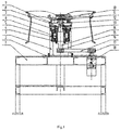
Fig. 1 is a structural schematic diagram of a wheel runout detection device of the present invention. -
Fig. 2 is a structural schematic diagram of an expansion sleeve in the wheel runout detection device of the present invention. -
Fig. 3 is a structural schematic diagram of an expansion core in the wheel runout detection device of the present invention. -
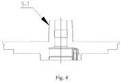
Fig. 4 is a structural schematic diagram of a flange in the wheel runout detection device of the present invention. - In which: 1-frame, 2-bottom plate, 3-base, 4-bearing, 5-spacing ring, 6-shaft sleeve, 7-bearing end cover, 8-flange plate, 9-flange, 10-expansion core, 11-expansion sleeve, 12-pull rod, 13-cylinder, 14-connecting shaft, 15-synchronous gear A, 16-synchronous belt, 17-synchronous gear B, 18-servo motor.
- Details and working conditions of a specific device provided by the present invention will be described in detail below in combination with the accompanying drawings.
- A wheel runout detection device in the present invention is mainly composed of a
frame 1, a bottom plate 2, a base 3, bearings 4, a spacing ring 5, a shaft sleeve 6, a bearing end cover 7, a flange plate 8, aflange 9, anexpansion core 10, an expansion sleeve 11, apull rod 12, acylinder 13, a connecting shaft 14, a synchronous gear A 15, a synchronous belt 16, a synchronous gear B 17 and a servo motor 18. The bottom plate 2 and the servo motor 18 are fixed on theframe 1, the base 3 is fixed on the bottom plate 2, the two bearings 4 and the spacing ring 5 are closed on the base 3 by the bearing end cover 7, the two bearings 4 are connected by the spacing ring 5, the shaft sleeve 6 is connected with the bearings 4, two ends of the shaft sleeve 6 are respectively connected with the synchronous gear A 15 and the flange plate 8, the synchronous gear B 17 is mounted on the output shaft of the servo motor 18, the synchronous gear A 15 is connected with the synchronous gear B 17 via the synchronous belt 16, theflange 9, the expansion sleeve 11 and thecylinder 13 are mounted on the flange plate 8, two ends of the connecting shaft 14 are respectively connected with the output shaft of thecylinder 13 and theexpansion core 10, the outer diameter of theexpansion core 10 is of an inverse cone structure 10-1, the inner wall of theexpansion core 10 is of a positive cone structure 10-2, and the outer diameter inverse cone surface 10-1 and inner wall positive cone surface 10-2 of theexpansion core 10 are respectively matched with an upper positive cone surface 11-1 of the expansion sleeve 11 and an upper inverse cone structure 9-1 of the flange plate 8. Thecylinder 13 pulls theexpansion core 10 down, and through cone surface fits between theexpansion core 10 and the expansion sleeve 11 and between theexpansion core 10 and the flange plate 8, the outer diameter of the expansion sleeve 11 is expanded, so that the central hole of a wheel is tightened and high-precision radial positioning of the wheel is realized. The servo motor 18 drives theflange 9, the expansion sleeve 11 and the wheel to rotate via the synchronous gear A 15, the synchronous belt 16 and the synchronous gear B 17. - In actual use, when a wheel is put onto this device, the central hole of the wheel is aligned with the expansion sleeve 11, the
cylinder 13 pulls theexpansion core 10 down via thepull rod 12, and through cone surface fits between theexpansion core 10 and the expansion sleeve 11 and between theexpansion core 10 and the flange plate 8, the outer diameter of the expansion sleeve 11 is expanded, so that the central hole of the wheel is tightened and high-precision radial positioning of the wheel is realized. The servo motor 18 drives theflange 9, the expansion sleeve 11 and the wheel to rotate via the synchronous gear A 15, the synchronous belt 16 and the synchronous gear B 17, and then runout of the bead seat of the wheel is detected via a special instrument
Claims (1)
- A wheel runout detection device, composed of a frame (1), a bottom plate (2), a base (3), bearings (4), a spacing ring (5), a shaft sleeve (6), a bearing end cover (7), a flange plate (8), a flange (9), an expansion core (10), an expansion sleeve (11), a pull rod (12), a cylinder (13), a connecting shaft (14), a synchronous gear A (15), a synchronous belt (16), a synchronous gear B (17) and a servo motor (18),characterized in that the bottom plate (2) and the servo motor (18) are fixed on the frame (1), the base (3) is fixed on the bottom plate (2), the two bearings (4) and the spacing ring (5) are closed on the base (3) by the bearing end cover (7), the two bearings (4) are connected by the spacing ring (5), the shaft sleeve (6) is connected with the bearings (4), two ends of the shaft sleeve (6) are respectively connected with the synchronous gear A (15) and the flange plate (8), the synchronous gear B (17) is mounted on the output shaft of the servo motor (18), the synchronous gear A (15) is connected with the synchronous gear B (17) via the synchronous belt (16),wherein the flange (9), the expansion sleeve (11) and the cylinder (13) are mounted on the flange plate (8), two ends of the connecting shaft (14) are respectively connected with the output shaft of the cylinder (13) and the expansion core (10), the outer diameter of the expansion core (10) is of an inverse cone structure (10-1), the inner wall of the expansion core is of a positive cone structure (10-2), and the outer diameter inverse cone surface (10-1) and inner wall positive cone surface (10-2) of the expansion core (10) are respectively matched with an upper positive cone surface (11-1) of the expansion sleeve (11) and an upper inverse cone structure (9-1) of the flange plate (8), and wherein the cylinder (13) is arranged to pull the expansion core (10) down so that, through cone surface fits between the expansion core (10) and the expansion sleeve (11) and between the expansion core (10) and the flange plate (8), the outer diameter of the expansion sleeve (11) can be expanded, so that the central hole of the wheel is tightened and high-precision radial positioning of the wheel is realized, andwherein the servo motor (18) is configured to drive the flange (9), the expansion sleeve (11) and the wheel to rotate via the synchronous gear A (15), the synchronous belt (16) and the synchronous gear B (17).
Applications Claiming Priority (1)
| Application Number | Priority Date | Filing Date | Title |
|---|---|---|---|
| CN201710635541.5A CN107328377A (en) | 2017-07-31 | 2017-07-31 | A kind of wheel hop detection means |
Publications (2)
| Publication Number | Publication Date |
|---|---|
| EP3438598A1 EP3438598A1 (en) | 2019-02-06 |
| EP3438598B1 true EP3438598B1 (en) | 2021-09-29 |
Family
ID=60227820
Family Applications (1)
| Application Number | Title | Priority Date | Filing Date |
|---|---|---|---|
| EP18186203.8A Active EP3438598B1 (en) | 2017-07-31 | 2018-07-28 | Wheel runout detection device |
Country Status (4)
| Country | Link |
|---|---|
| US (1) | US10502663B2 (en) |
| EP (1) | EP3438598B1 (en) |
| CN (1) | CN107328377A (en) |
| MA (1) | MA44566B1 (en) |
Families Citing this family (16)
| Publication number | Priority date | Publication date | Assignee | Title |
|---|---|---|---|---|
| CN107907081A (en) * | 2017-11-30 | 2018-04-13 | 中信戴卡股份有限公司 | A kind of device for being used to detect wheel hop |
| CN108088345B (en) * | 2017-12-14 | 2019-11-19 | 爱雷德机床有限公司 | A device for measuring the runout of the end cover of a planetary double-through-flow motor |
| CN108788619A (en) * | 2017-12-21 | 2018-11-13 | 中信戴卡股份有限公司 | A kind of wheel end surface measurement and means for correcting |
| CN108273875B (en) * | 2017-12-21 | 2023-11-17 | 中信戴卡股份有限公司 | Improved wheel end face detection and correction device |
| CN109141938A (en) * | 2018-11-06 | 2019-01-04 | 汽-大众汽车有限公司 | A kind of tyre tread Abrasion detecting instrument |
| CN109373952A (en) * | 2018-11-07 | 2019-02-22 | 中信戴卡股份有限公司 | Wheel rim room device in a kind of on-line checking wheel |
| CN109813493B (en) * | 2019-02-27 | 2023-11-03 | 中信戴卡股份有限公司 | Verification hub and verification method of motor vehicle hub runout testing machine |
| CN110567338A (en) * | 2019-10-12 | 2019-12-13 | 鹰普航空零部件(无锡)有限公司 | End face runout detection device with step hole part |
| CN111947837B (en) * | 2020-09-01 | 2024-12-17 | 上海剑平动平衡机制造有限公司 | Dynamic balancing machine for detecting dynamic balancing quantity of wheel |
| CN112577594B (en) * | 2020-12-29 | 2023-05-16 | 上海渤元信息科技有限公司 | Verification device and verification method for abnormal sound of automobile shaft sleeve |
| CN112880511B (en) * | 2021-01-12 | 2023-03-28 | 深圳市小云智控技术有限公司 | Equipment suitable for detecting number of holes in inner wall of multi-model automobile hub |
| CN113967553A (en) * | 2021-11-10 | 2022-01-25 | 浙江跃岭股份有限公司 | Suspension device for spraying automobile hub |
| CN115371518B (en) * | 2022-09-22 | 2025-04-01 | 浙江斯凯福汽车零部件有限公司 | A bearing inner ring runout detection device |
| CN116989634A (en) * | 2023-09-27 | 2023-11-03 | 万向钱潮股份公司 | Positioning tool for detecting journal position and application method thereof |
| CN117490528B (en) * | 2023-12-29 | 2024-03-19 | 常州合泰电机电器股份有限公司 | Motor testing equipment and method of use |
| CN117968938B (en) * | 2024-03-28 | 2024-06-04 | 辽宁天凯汽车部件制造有限公司 | Inspection tool for engine crankshaft vibration damping pulley |
Family Cites Families (21)
| Publication number | Priority date | Publication date | Assignee | Title |
|---|---|---|---|---|
| US3279084A (en) * | 1965-01-08 | 1966-10-18 | Strick Corp | Trailer axle misalignment and wheel runout indicator and method |
| DE8325783U1 (en) | 1983-09-08 | 1983-12-29 | Gebr. Hofmann Gmbh & Co Kg Maschinenfabrik, 6100 Darmstadt | QUICK-RELEASE NUTS FOR CLAMPING MOTOR VEHICLE WHEELS, ESPECIALLY ON THE CLAMPING FLANGE OF A BALANCING MACHINE |
| US4569140A (en) * | 1984-04-27 | 1986-02-11 | Hobson John A | Thrust line wheel alignment apparatus and method |
| US4854702A (en) * | 1987-12-14 | 1989-08-08 | Hunter Engineering Company | Vehicle wheel alignment apparatus and method of use |
| DE4200380C2 (en) | 1992-01-09 | 1996-09-19 | Hofmann Werkstatt Technik | Method and device for tensioning and releasing a rotor, in particular a motor vehicle wheel, on a main shaft driven by a motor of an unbalance measuring arrangement, in particular a wheel balancing machine |
| US5919238A (en) * | 1998-03-04 | 1999-07-06 | Ford Global Technologies, Inc. | Method for aligning a vehicle suspension |
| JP4611488B2 (en) * | 2000-04-21 | 2011-01-12 | 本田技研工業株式会社 | Wheel runout measurement method |
| US7640673B2 (en) * | 2007-08-01 | 2010-01-05 | Snap-On Incorporated | Calibration and operation of wheel alignment systems |
| CN201470924U (en) * | 2009-06-18 | 2010-05-19 | 中信戴卡轮毂制造股份有限公司 | Improved machining center clamp |
| CN201931105U (en) * | 2010-12-17 | 2011-08-17 | 山东济宁特力机床有限公司 | Taper sleeve expander fixture of numerical-control lathe |
| CN202442665U (en) * | 2012-03-01 | 2012-09-19 | 中信戴卡轮毂制造股份有限公司 | Wheel jumping detecting device |
| CN203610706U (en) * | 2013-09-30 | 2014-05-28 | 江苏南铸科技股份有限公司 | Self-positioning and locking tool for barrel-shaped workpiece |
| CN203479274U (en) * | 2013-10-18 | 2014-03-12 | 中信戴卡股份有限公司 | Wheel blank positioning detecting device |
| CN103557811B (en) * | 2013-10-18 | 2015-12-09 | 中信戴卡股份有限公司 | A kind of wheel blanks locating and detecting device |
| CN104493644A (en) | 2014-12-18 | 2015-04-08 | 中信戴卡股份有限公司 | Machining center skew detector |
| CN205733071U (en) * | 2016-05-17 | 2016-11-30 | 洛阳华冠齿轮股份有限公司 | A kind of novel Internal hole positioning, Tensioning structure |
| CN105928476B (en) * | 2016-06-29 | 2018-07-20 | 中信戴卡股份有限公司 | A kind of wheel on-line checking trip gear |
| CN105922801B (en) * | 2016-06-29 | 2018-03-16 | 中信戴卡股份有限公司 | A kind of automatic carving device of wheel |
| US10337961B2 (en) * | 2017-04-27 | 2019-07-02 | Gm Global Technology Operations Llc. | Method of analyzing radial force variation in a tire/wheel assembly |
| CN107283339B (en) * | 2017-07-31 | 2022-12-02 | 中信戴卡股份有限公司 | Aluminum alloy wheel hub positioning fixture |
| CN107662120A (en) * | 2017-10-31 | 2018-02-06 | 中信戴卡股份有限公司 | A kind of device for aluminum-alloy wheel correction |
-
2017
- 2017-07-31 CN CN201710635541.5A patent/CN107328377A/en active Pending
- 2017-12-13 US US15/840,748 patent/US10502663B2/en active Active
-
2018
- 2018-07-28 MA MA44566A patent/MA44566B1/en unknown
- 2018-07-28 EP EP18186203.8A patent/EP3438598B1/en active Active
Also Published As
| Publication number | Publication date |
|---|---|
| MA44566B1 (en) | 2021-12-31 |
| US20190033173A1 (en) | 2019-01-31 |
| CN107328377A (en) | 2017-11-07 |
| MA44566A (en) | 2021-06-02 |
| US10502663B2 (en) | 2019-12-10 |
| EP3438598A1 (en) | 2019-02-06 |
Similar Documents
| Publication | Publication Date | Title |
|---|---|---|
| EP3438598A1 (en) | Wheel runout detection device | |
| CN108907838A (en) | A kind of Thin-wall Revolving Part Self adapting fixture | |
| CN201543853U (en) | A self-centering three-jaw chuck | |
| CN104772563B (en) | Method for manufacturing automobile aluminum alloy hub | |
| CN111947837A (en) | A dynamic balancing machine for detecting the dynamic balance of wheels | |
| CN105071606B (en) | A kind of silicon steel plate stacking frock of electric automobile outer-rotor type in-wheel motor | |
| CN202028940U (en) | Machining fixture for automobile hub | |
| CN219901889U (en) | Automobile shock absorber ware casing processingequipment | |
| CN210139203U (en) | Clamp for bearing machining | |
| CN203343739U (en) | Brake surface finish machining and positioning device for automobile hub with brake drum assembly | |
| US10605301B2 (en) | Secondary clamping device for wheel | |
| CN206732290U (en) | Taper hole gear grinding clamp | |
| CN202668204U (en) | Positioning tool for turning labyrinth end cover of track shaft | |
| CN110695425A (en) | Brake block terminal surface fluting device | |
| CN205817657U (en) | A kind of cubing clamping device and comprise the cubing of this cubing clamping device | |
| CN211032029U (en) | Rotatable aluminum alloy automobile wheel hub dress trim cover fixing support | |
| CN214040595U (en) | Automobile wheel hub acceleration test device | |
| CN212220598U (en) | Low-speed impact test tool clamp | |
| CN209049962U (en) | Multistation automatic buffer bracket hole punched device | |
| CN206550683U (en) | A kind of centering and clamping apparatus of wheel hub | |
| CN108857258A (en) | A kind of automotive hub prosthetic appliance | |
| CN207757300U (en) | A rotary tool magazine | |
| CN216883379U (en) | Three-jaw chuck clamping device | |
| CN212192694U (en) | Locating tool clamp for polishing of wheel spoke surface | |
| CN204294948U (en) | Milling machine is with holding out against fixture |
Legal Events
| Date | Code | Title | Description |
|---|---|---|---|
| PUAI | Public reference made under article 153(3) epc to a published international application that has entered the european phase |
Free format text: ORIGINAL CODE: 0009012 |
|
| STAA | Information on the status of an ep patent application or granted ep patent |
Free format text: STATUS: REQUEST FOR EXAMINATION WAS MADE |
|
| 17P | Request for examination filed |
Effective date: 20180728 |
|
| AK | Designated contracting states |
Kind code of ref document: A1 Designated state(s): AL AT BE BG CH CY CZ DE DK EE ES FI FR GB GR HR HU IE IS IT LI LT LU LV MC MK MT NL NO PL PT RO RS SE SI SK SM TR |
|
| AX | Request for extension of the european patent |
Extension state: BA ME |
|
| GRAP | Despatch of communication of intention to grant a patent |
Free format text: ORIGINAL CODE: EPIDOSNIGR1 |
|
| STAA | Information on the status of an ep patent application or granted ep patent |
Free format text: STATUS: GRANT OF PATENT IS INTENDED |
|
| GRAS | Grant fee paid |
Free format text: ORIGINAL CODE: EPIDOSNIGR3 |
|
| RIC1 | Information provided on ipc code assigned before grant |
Ipc: G01M 17/013 20060101ALI20210427BHEP Ipc: G01M 1/04 20060101ALI20210427BHEP Ipc: G01B 5/00 20060101AFI20210427BHEP |
|
| INTG | Intention to grant announced |
Effective date: 20210517 |
|
| GRAA | (expected) grant |
Free format text: ORIGINAL CODE: 0009210 |
|
| STAA | Information on the status of an ep patent application or granted ep patent |
Free format text: STATUS: THE PATENT HAS BEEN GRANTED |
|
| AK | Designated contracting states |
Kind code of ref document: B1 Designated state(s): AL AT BE BG CH CY CZ DE DK EE ES FI FR GB GR HR HU IE IS IT LI LT LU LV MC MK MT NL NO PL PT RO RS SE SI SK SM TR |
|
| REG | Reference to a national code |
Ref country code: GB Ref legal event code: FG4D |
|
| REG | Reference to a national code |
Ref country code: CH Ref legal event code: EP Ref country code: AT Ref legal event code: REF Ref document number: 1434564 Country of ref document: AT Kind code of ref document: T Effective date: 20211015 |
|
| REG | Reference to a national code |
Ref country code: DE Ref legal event code: R096 Ref document number: 602018024158 Country of ref document: DE |
|
| REG | Reference to a national code |
Ref country code: IE Ref legal event code: FG4D |
|
| REG | Reference to a national code |
Ref country code: MA Ref legal event code: VAGR Ref document number: 44566 Country of ref document: MA Kind code of ref document: B1 |
|
| REG | Reference to a national code |
Ref country code: LT Ref legal event code: MG9D |
|
| PG25 | Lapsed in a contracting state [announced via postgrant information from national office to epo] |
Ref country code: SE Free format text: LAPSE BECAUSE OF FAILURE TO SUBMIT A TRANSLATION OF THE DESCRIPTION OR TO PAY THE FEE WITHIN THE PRESCRIBED TIME-LIMIT Effective date: 20210929 Ref country code: RS Free format text: LAPSE BECAUSE OF FAILURE TO SUBMIT A TRANSLATION OF THE DESCRIPTION OR TO PAY THE FEE WITHIN THE PRESCRIBED TIME-LIMIT Effective date: 20210929 Ref country code: HR Free format text: LAPSE BECAUSE OF FAILURE TO SUBMIT A TRANSLATION OF THE DESCRIPTION OR TO PAY THE FEE WITHIN THE PRESCRIBED TIME-LIMIT Effective date: 20210929 Ref country code: FI Free format text: LAPSE BECAUSE OF FAILURE TO SUBMIT A TRANSLATION OF THE DESCRIPTION OR TO PAY THE FEE WITHIN THE PRESCRIBED TIME-LIMIT Effective date: 20210929 Ref country code: NO Free format text: LAPSE BECAUSE OF FAILURE TO SUBMIT A TRANSLATION OF THE DESCRIPTION OR TO PAY THE FEE WITHIN THE PRESCRIBED TIME-LIMIT Effective date: 20211229 Ref country code: BG Free format text: LAPSE BECAUSE OF FAILURE TO SUBMIT A TRANSLATION OF THE DESCRIPTION OR TO PAY THE FEE WITHIN THE PRESCRIBED TIME-LIMIT Effective date: 20211229 Ref country code: LT Free format text: LAPSE BECAUSE OF FAILURE TO SUBMIT A TRANSLATION OF THE DESCRIPTION OR TO PAY THE FEE WITHIN THE PRESCRIBED TIME-LIMIT Effective date: 20210929 |
|
| REG | Reference to a national code |
Ref country code: NL Ref legal event code: MP Effective date: 20210929 |
|
| REG | Reference to a national code |
Ref country code: AT Ref legal event code: MK05 Ref document number: 1434564 Country of ref document: AT Kind code of ref document: T Effective date: 20210929 |
|
| PG25 | Lapsed in a contracting state [announced via postgrant information from national office to epo] |
Ref country code: LV Free format text: LAPSE BECAUSE OF FAILURE TO SUBMIT A TRANSLATION OF THE DESCRIPTION OR TO PAY THE FEE WITHIN THE PRESCRIBED TIME-LIMIT Effective date: 20210929 Ref country code: GR Free format text: LAPSE BECAUSE OF FAILURE TO SUBMIT A TRANSLATION OF THE DESCRIPTION OR TO PAY THE FEE WITHIN THE PRESCRIBED TIME-LIMIT Effective date: 20211230 |
|
| PG25 | Lapsed in a contracting state [announced via postgrant information from national office to epo] |
Ref country code: AT Free format text: LAPSE BECAUSE OF FAILURE TO SUBMIT A TRANSLATION OF THE DESCRIPTION OR TO PAY THE FEE WITHIN THE PRESCRIBED TIME-LIMIT Effective date: 20210929 |
|
| PG25 | Lapsed in a contracting state [announced via postgrant information from national office to epo] |
Ref country code: IS Free format text: LAPSE BECAUSE OF FAILURE TO SUBMIT A TRANSLATION OF THE DESCRIPTION OR TO PAY THE FEE WITHIN THE PRESCRIBED TIME-LIMIT Effective date: 20220129 Ref country code: SK Free format text: LAPSE BECAUSE OF FAILURE TO SUBMIT A TRANSLATION OF THE DESCRIPTION OR TO PAY THE FEE WITHIN THE PRESCRIBED TIME-LIMIT Effective date: 20210929 Ref country code: RO Free format text: LAPSE BECAUSE OF FAILURE TO SUBMIT A TRANSLATION OF THE DESCRIPTION OR TO PAY THE FEE WITHIN THE PRESCRIBED TIME-LIMIT Effective date: 20210929 Ref country code: PT Free format text: LAPSE BECAUSE OF FAILURE TO SUBMIT A TRANSLATION OF THE DESCRIPTION OR TO PAY THE FEE WITHIN THE PRESCRIBED TIME-LIMIT Effective date: 20220131 Ref country code: PL Free format text: LAPSE BECAUSE OF FAILURE TO SUBMIT A TRANSLATION OF THE DESCRIPTION OR TO PAY THE FEE WITHIN THE PRESCRIBED TIME-LIMIT Effective date: 20210929 Ref country code: NL Free format text: LAPSE BECAUSE OF FAILURE TO SUBMIT A TRANSLATION OF THE DESCRIPTION OR TO PAY THE FEE WITHIN THE PRESCRIBED TIME-LIMIT Effective date: 20210929 Ref country code: ES Free format text: LAPSE BECAUSE OF FAILURE TO SUBMIT A TRANSLATION OF THE DESCRIPTION OR TO PAY THE FEE WITHIN THE PRESCRIBED TIME-LIMIT Effective date: 20210929 Ref country code: EE Free format text: LAPSE BECAUSE OF FAILURE TO SUBMIT A TRANSLATION OF THE DESCRIPTION OR TO PAY THE FEE WITHIN THE PRESCRIBED TIME-LIMIT Effective date: 20210929 Ref country code: CZ Free format text: LAPSE BECAUSE OF FAILURE TO SUBMIT A TRANSLATION OF THE DESCRIPTION OR TO PAY THE FEE WITHIN THE PRESCRIBED TIME-LIMIT Effective date: 20210929 Ref country code: AL Free format text: LAPSE BECAUSE OF FAILURE TO SUBMIT A TRANSLATION OF THE DESCRIPTION OR TO PAY THE FEE WITHIN THE PRESCRIBED TIME-LIMIT Effective date: 20210929 |
|
| REG | Reference to a national code |
Ref country code: DE Ref legal event code: R097 Ref document number: 602018024158 Country of ref document: DE |
|
| PG25 | Lapsed in a contracting state [announced via postgrant information from national office to epo] |
Ref country code: DK Free format text: LAPSE BECAUSE OF FAILURE TO SUBMIT A TRANSLATION OF THE DESCRIPTION OR TO PAY THE FEE WITHIN THE PRESCRIBED TIME-LIMIT Effective date: 20210929 |
|
| PLBE | No opposition filed within time limit |
Free format text: ORIGINAL CODE: 0009261 |
|
| STAA | Information on the status of an ep patent application or granted ep patent |
Free format text: STATUS: NO OPPOSITION FILED WITHIN TIME LIMIT |
|
| 26N | No opposition filed |
Effective date: 20220630 |
|
| PG25 | Lapsed in a contracting state [announced via postgrant information from national office to epo] |
Ref country code: SI Free format text: LAPSE BECAUSE OF FAILURE TO SUBMIT A TRANSLATION OF THE DESCRIPTION OR TO PAY THE FEE WITHIN THE PRESCRIBED TIME-LIMIT Effective date: 20210929 |
|
| PG25 | Lapsed in a contracting state [announced via postgrant information from national office to epo] |
Ref country code: IT Free format text: LAPSE BECAUSE OF FAILURE TO SUBMIT A TRANSLATION OF THE DESCRIPTION OR TO PAY THE FEE WITHIN THE PRESCRIBED TIME-LIMIT Effective date: 20210929 |
|
| PG25 | Lapsed in a contracting state [announced via postgrant information from national office to epo] |
Ref country code: MC Free format text: LAPSE BECAUSE OF FAILURE TO SUBMIT A TRANSLATION OF THE DESCRIPTION OR TO PAY THE FEE WITHIN THE PRESCRIBED TIME-LIMIT Effective date: 20210929 |
|
| REG | Reference to a national code |
Ref country code: CH Ref legal event code: PL |
|
| GBPC | Gb: european patent ceased through non-payment of renewal fee |
Effective date: 20220728 |
|
| REG | Reference to a national code |
Ref country code: BE Ref legal event code: MM Effective date: 20220731 |
|
| PG25 | Lapsed in a contracting state [announced via postgrant information from national office to epo] |
Ref country code: LU Free format text: LAPSE BECAUSE OF NON-PAYMENT OF DUE FEES Effective date: 20220728 Ref country code: LI Free format text: LAPSE BECAUSE OF NON-PAYMENT OF DUE FEES Effective date: 20220731 Ref country code: CH Free format text: LAPSE BECAUSE OF NON-PAYMENT OF DUE FEES Effective date: 20220731 |
|
| PG25 | Lapsed in a contracting state [announced via postgrant information from national office to epo] |
Ref country code: GB Free format text: LAPSE BECAUSE OF NON-PAYMENT OF DUE FEES Effective date: 20220728 Ref country code: BE Free format text: LAPSE BECAUSE OF NON-PAYMENT OF DUE FEES Effective date: 20220731 |
|
| PG25 | Lapsed in a contracting state [announced via postgrant information from national office to epo] |
Ref country code: IE Free format text: LAPSE BECAUSE OF NON-PAYMENT OF DUE FEES Effective date: 20220728 |
|
| PG25 | Lapsed in a contracting state [announced via postgrant information from national office to epo] |
Ref country code: HU Free format text: LAPSE BECAUSE OF FAILURE TO SUBMIT A TRANSLATION OF THE DESCRIPTION OR TO PAY THE FEE WITHIN THE PRESCRIBED TIME-LIMIT; INVALID AB INITIO Effective date: 20180728 |
|
| PG25 | Lapsed in a contracting state [announced via postgrant information from national office to epo] |
Ref country code: SM Free format text: LAPSE BECAUSE OF FAILURE TO SUBMIT A TRANSLATION OF THE DESCRIPTION OR TO PAY THE FEE WITHIN THE PRESCRIBED TIME-LIMIT Effective date: 20210929 Ref country code: MK Free format text: LAPSE BECAUSE OF FAILURE TO SUBMIT A TRANSLATION OF THE DESCRIPTION OR TO PAY THE FEE WITHIN THE PRESCRIBED TIME-LIMIT Effective date: 20210929 Ref country code: CY Free format text: LAPSE BECAUSE OF FAILURE TO SUBMIT A TRANSLATION OF THE DESCRIPTION OR TO PAY THE FEE WITHIN THE PRESCRIBED TIME-LIMIT Effective date: 20210929 |
|
| PG25 | Lapsed in a contracting state [announced via postgrant information from national office to epo] |
Ref country code: TR Free format text: LAPSE BECAUSE OF FAILURE TO SUBMIT A TRANSLATION OF THE DESCRIPTION OR TO PAY THE FEE WITHIN THE PRESCRIBED TIME-LIMIT Effective date: 20210929 |
|
| PG25 | Lapsed in a contracting state [announced via postgrant information from national office to epo] |
Ref country code: MT Free format text: LAPSE BECAUSE OF FAILURE TO SUBMIT A TRANSLATION OF THE DESCRIPTION OR TO PAY THE FEE WITHIN THE PRESCRIBED TIME-LIMIT Effective date: 20210929 |
|
| PGFP | Annual fee paid to national office [announced via postgrant information from national office to epo] |
Ref country code: DE Payment date: 20250711 Year of fee payment: 8 |
|
| PGFP | Annual fee paid to national office [announced via postgrant information from national office to epo] |
Ref country code: FR Payment date: 20250730 Year of fee payment: 8 |
|
| VS25 | Lapsed in a validation state [announced via postgrant information from nat. office to epo] |
Ref country code: MA Free format text: LAPSE BECAUSE OF NON-PAYMENT OF DUE FEES Effective date: 20230729 |
|
| VSFP | Annual fee paid to validation state [announced via postgrant information from national office to epo] |
Ref country code: MA Payment date: 20220803 Year of fee payment: 5 |