EP3438493A1 - Hollow spring member and manufacturing method therefor - Google Patents
Hollow spring member and manufacturing method therefor Download PDFInfo
- Publication number
- EP3438493A1 EP3438493A1 EP17775321.7A EP17775321A EP3438493A1 EP 3438493 A1 EP3438493 A1 EP 3438493A1 EP 17775321 A EP17775321 A EP 17775321A EP 3438493 A1 EP3438493 A1 EP 3438493A1
- Authority
- EP
- European Patent Office
- Prior art keywords
- hollow
- terminal
- enclosed space
- hollow rod
- rust
- Prior art date
- Legal status (The legal status is an assumption and is not a legal conclusion. Google has not performed a legal analysis and makes no representation as to the accuracy of the status listed.)
- Granted
Links
Images



Classifications
-
- B—PERFORMING OPERATIONS; TRANSPORTING
- B60—VEHICLES IN GENERAL
- B60G—VEHICLE SUSPENSION ARRANGEMENTS
- B60G21/00—Interconnection systems for two or more resiliently-suspended wheels, e.g. for stabilising a vehicle body with respect to acceleration, deceleration or centrifugal forces
- B60G21/02—Interconnection systems for two or more resiliently-suspended wheels, e.g. for stabilising a vehicle body with respect to acceleration, deceleration or centrifugal forces permanently interconnected
- B60G21/04—Interconnection systems for two or more resiliently-suspended wheels, e.g. for stabilising a vehicle body with respect to acceleration, deceleration or centrifugal forces permanently interconnected mechanically
- B60G21/05—Interconnection systems for two or more resiliently-suspended wheels, e.g. for stabilising a vehicle body with respect to acceleration, deceleration or centrifugal forces permanently interconnected mechanically between wheels on the same axle but on different sides of the vehicle, i.e. the left and right wheel suspensions being interconnected
- B60G21/055—Stabiliser bars
-
- F—MECHANICAL ENGINEERING; LIGHTING; HEATING; WEAPONS; BLASTING
- F16—ENGINEERING ELEMENTS AND UNITS; GENERAL MEASURES FOR PRODUCING AND MAINTAINING EFFECTIVE FUNCTIONING OF MACHINES OR INSTALLATIONS; THERMAL INSULATION IN GENERAL
- F16F—SPRINGS; SHOCK-ABSORBERS; MEANS FOR DAMPING VIBRATION
- F16F1/00—Springs
- F16F1/02—Springs made of steel or other material having low internal friction; Wound, torsion, leaf, cup, ring or the like springs, the material of the spring not being relevant
-
- F—MECHANICAL ENGINEERING; LIGHTING; HEATING; WEAPONS; BLASTING
- F16—ENGINEERING ELEMENTS AND UNITS; GENERAL MEASURES FOR PRODUCING AND MAINTAINING EFFECTIVE FUNCTIONING OF MACHINES OR INSTALLATIONS; THERMAL INSULATION IN GENERAL
- F16F—SPRINGS; SHOCK-ABSORBERS; MEANS FOR DAMPING VIBRATION
- F16F1/00—Springs
- F16F1/02—Springs made of steel or other material having low internal friction; Wound, torsion, leaf, cup, ring or the like springs, the material of the spring not being relevant
- F16F1/04—Wound springs
- F16F1/042—Wound springs characterised by the cross-section of the wire
-
- F—MECHANICAL ENGINEERING; LIGHTING; HEATING; WEAPONS; BLASTING
- F16—ENGINEERING ELEMENTS AND UNITS; GENERAL MEASURES FOR PRODUCING AND MAINTAINING EFFECTIVE FUNCTIONING OF MACHINES OR INSTALLATIONS; THERMAL INSULATION IN GENERAL
- F16F—SPRINGS; SHOCK-ABSORBERS; MEANS FOR DAMPING VIBRATION
- F16F1/00—Springs
- F16F1/02—Springs made of steel or other material having low internal friction; Wound, torsion, leaf, cup, ring or the like springs, the material of the spring not being relevant
- F16F1/14—Torsion springs consisting of bars or tubes
-
- B—PERFORMING OPERATIONS; TRANSPORTING
- B23—MACHINE TOOLS; METAL-WORKING NOT OTHERWISE PROVIDED FOR
- B23P—METAL-WORKING NOT OTHERWISE PROVIDED FOR; COMBINED OPERATIONS; UNIVERSAL MACHINE TOOLS
- B23P23/00—Machines or arrangements of machines for performing specified combinations of different metal-working operations not covered by a single other subclass
- B23P23/04—Machines or arrangements of machines for performing specified combinations of different metal-working operations not covered by a single other subclass for both machining and other metal-working operations
-
- B—PERFORMING OPERATIONS; TRANSPORTING
- B60—VEHICLES IN GENERAL
- B60G—VEHICLE SUSPENSION ARRANGEMENTS
- B60G2202/00—Indexing codes relating to the type of spring, damper or actuator
- B60G2202/10—Type of spring
- B60G2202/12—Wound spring
-
- B—PERFORMING OPERATIONS; TRANSPORTING
- B60—VEHICLES IN GENERAL
- B60G—VEHICLE SUSPENSION ARRANGEMENTS
- B60G2202/00—Indexing codes relating to the type of spring, damper or actuator
- B60G2202/10—Type of spring
- B60G2202/13—Torsion spring
- B60G2202/135—Stabiliser bar and/or tube
-
- B—PERFORMING OPERATIONS; TRANSPORTING
- B60—VEHICLES IN GENERAL
- B60G—VEHICLE SUSPENSION ARRANGEMENTS
- B60G2206/00—Indexing codes related to the manufacturing of suspensions: constructional features, the materials used, procedures or tools
- B60G2206/01—Constructional features of suspension elements, e.g. arms, dampers, springs
- B60G2206/012—Hollow or tubular elements
-
- B—PERFORMING OPERATIONS; TRANSPORTING
- B60—VEHICLES IN GENERAL
- B60G—VEHICLE SUSPENSION ARRANGEMENTS
- B60G2206/00—Indexing codes related to the manufacturing of suspensions: constructional features, the materials used, procedures or tools
- B60G2206/01—Constructional features of suspension elements, e.g. arms, dampers, springs
- B60G2206/017—Constructional features of suspension elements, e.g. arms, dampers, springs forming an eye for the bushing
-
- B—PERFORMING OPERATIONS; TRANSPORTING
- B60—VEHICLES IN GENERAL
- B60G—VEHICLE SUSPENSION ARRANGEMENTS
- B60G2206/00—Indexing codes related to the manufacturing of suspensions: constructional features, the materials used, procedures or tools
- B60G2206/01—Constructional features of suspension elements, e.g. arms, dampers, springs
- B60G2206/40—Constructional features of dampers and/or springs
- B60G2206/42—Springs
- B60G2206/427—Stabiliser bars or tubes
-
- B—PERFORMING OPERATIONS; TRANSPORTING
- B60—VEHICLES IN GENERAL
- B60G—VEHICLE SUSPENSION ARRANGEMENTS
- B60G2206/00—Indexing codes related to the manufacturing of suspensions: constructional features, the materials used, procedures or tools
- B60G2206/01—Constructional features of suspension elements, e.g. arms, dampers, springs
- B60G2206/70—Materials used in suspensions
- B60G2206/72—Steel
-
- B—PERFORMING OPERATIONS; TRANSPORTING
- B60—VEHICLES IN GENERAL
- B60G—VEHICLE SUSPENSION ARRANGEMENTS
- B60G2206/00—Indexing codes related to the manufacturing of suspensions: constructional features, the materials used, procedures or tools
- B60G2206/01—Constructional features of suspension elements, e.g. arms, dampers, springs
- B60G2206/70—Materials used in suspensions
- B60G2206/72—Steel
- B60G2206/724—Wires, bars or the like
-
- B—PERFORMING OPERATIONS; TRANSPORTING
- B60—VEHICLES IN GENERAL
- B60G—VEHICLE SUSPENSION ARRANGEMENTS
- B60G2206/00—Indexing codes related to the manufacturing of suspensions: constructional features, the materials used, procedures or tools
- B60G2206/01—Constructional features of suspension elements, e.g. arms, dampers, springs
- B60G2206/80—Manufacturing procedures
-
- B—PERFORMING OPERATIONS; TRANSPORTING
- B60—VEHICLES IN GENERAL
- B60G—VEHICLE SUSPENSION ARRANGEMENTS
- B60G2206/00—Indexing codes related to the manufacturing of suspensions: constructional features, the materials used, procedures or tools
- B60G2206/01—Constructional features of suspension elements, e.g. arms, dampers, springs
- B60G2206/80—Manufacturing procedures
- B60G2206/81—Shaping
- B60G2206/8103—Shaping by folding or bending
-
- B—PERFORMING OPERATIONS; TRANSPORTING
- B60—VEHICLES IN GENERAL
- B60G—VEHICLE SUSPENSION ARRANGEMENTS
- B60G2206/00—Indexing codes related to the manufacturing of suspensions: constructional features, the materials used, procedures or tools
- B60G2206/01—Constructional features of suspension elements, e.g. arms, dampers, springs
- B60G2206/80—Manufacturing procedures
- B60G2206/81—Shaping
- B60G2206/8103—Shaping by folding or bending
- B60G2206/81035—Shaping by folding or bending involving heating to relieve internal stresses
-
- B—PERFORMING OPERATIONS; TRANSPORTING
- B60—VEHICLES IN GENERAL
- B60G—VEHICLE SUSPENSION ARRANGEMENTS
- B60G2206/00—Indexing codes related to the manufacturing of suspensions: constructional features, the materials used, procedures or tools
- B60G2206/01—Constructional features of suspension elements, e.g. arms, dampers, springs
- B60G2206/80—Manufacturing procedures
- B60G2206/81—Shaping
- B60G2206/8106—Shaping by thermal treatment, e.g. curing hardening, vulcanisation
-
- B—PERFORMING OPERATIONS; TRANSPORTING
- B60—VEHICLES IN GENERAL
- B60G—VEHICLE SUSPENSION ARRANGEMENTS
- B60G2206/00—Indexing codes related to the manufacturing of suspensions: constructional features, the materials used, procedures or tools
- B60G2206/01—Constructional features of suspension elements, e.g. arms, dampers, springs
- B60G2206/80—Manufacturing procedures
- B60G2206/81—Shaping
- B60G2206/8112—Shaping by thermal spraying of molten material
-
- B—PERFORMING OPERATIONS; TRANSPORTING
- B60—VEHICLES IN GENERAL
- B60G—VEHICLE SUSPENSION ARRANGEMENTS
- B60G2206/00—Indexing codes related to the manufacturing of suspensions: constructional features, the materials used, procedures or tools
- B60G2206/01—Constructional features of suspension elements, e.g. arms, dampers, springs
- B60G2206/80—Manufacturing procedures
- B60G2206/84—Hardening
- B60G2206/8403—Shot-peening
Definitions
- the present invention relates to a hollow spring member such as a hollow stabilizer arranged in a suspension mechanism of a vehicle such as a car, and a method of manufacturing the same.
- a hollow stabilizer arranged in a suspension mechanism of a vehicle is constituted of a hollow rod made of steel (a steel pipe).
- the hollow stabilizer includes a torsion portion (a twisted portion), and a pair of arm portions (arms).
- the torsion portion extends in a width direction of the vehicle.
- the arm portions are extended from both ends of the torsion portion through curved portions, respectively.
- On a distal end of each of the arm portions an eye portion is formed.
- the torsion portion is supported on a vehicle body via a support portion, and the eye portion is connected to a suspension arm, etc., via a connecting member.
- the support portion includes a rubber bushing.
- One example of the connecting member is a link member (a stabilizer link).
- Patent Literature 1 or Patent Literature 2 describes an example of a hollow stabilizer. Eye portions are formed on both ends of the hollow stabilizer, respectively. A material of the hollow stabilizer is a hollow rod. By flattening end portions of the hollow rod in a radial direction of the hollow rod by upsetting, the eye portions are formed. In each of the eye portions, a through-hole is formed. A connecting member such as a stabilizer link is inserted into the through-hole. The eye portion is connected to a suspension arm, etc., via the connecting member.
- a spring member such as a stabilizer or a coil spring which constitutes the suspension mechanism is not an exception, and reducing the weight is an inevitable requirement.
- a high-strength spring steel for the material of the hollow stabilizer, attempts have been made to reduce the thickness of the hollow stabilizer as much as possible. Further, forming a compressive residual stress by performing shot peening on an inner surface of the hollow stabilizer helps to achieve high-strength in the hollow stabilizer.
- rust formed on the outer surface or the inner surface of the hollow stabilizer may cause a small pit.
- the pit grows to some degree the possibility that the pit may become a starting point of a break in the hollow stabilizer which is used under high stress is increased. Accordingly, some preventive measures must be taken against rust which will be formed on the inner surface, in addition to the outer surface, for the hollow stabilizer.
- a pair of terminal sealed portions is formed by flattening both ends of the hollow rod, an enclosed space is formed between these terminal sealed portions.
- a tapered gap in which the gap is narrowed toward an inner surface joined portion of the terminal sealed portion is formed.
- the gap is referred to as a terminal gap.
- the main cause of rust formed on the inner surface of the hollow stabilizer is moisture.
- moisture inevitably exists inside a hollow rod used as the material of the hollow stabilizer. This moisture becomes a cause of the rust.
- applying oil to the inner part of the hollow stabilizer has been considered.
- such oil cannot be adopted since it causes smoke or fire in a heat treatment which is performed in the step of manufacturing the hollow stabilizer.
- applying coating to the inner surface of the hollow stabilizer has been considered.
- drying a coating material applied to the inner surface of the hollow stabilizer takes long time.
- a part of the coating material exists at an end portion of the hollow rod, when the eye portions are formed by flattening the end portions, the coating material remaining at the end portion causes press bonding failure of the terminal sealed portion.
- an object of the present invention is to provide a hollow spring member capable of suppressing formation of rust on an inner surface, etc., of a hollow rod made of steel, and a method of manufacturing the same.
- a hollow spring member includes a hollow rod formed of a rod-shaped steel material. At both ends of the hollow rod, terminal sealed portions are formed, respectively. An enclosed space is formed between the pair of terminal sealed portions. At an end of the enclosed space, a terminal gap in which the gap is narrowed toward an inner surface joined portion of the terminal sealed portion is formed. Further, the hollow spring member comprises a volatile powdered rust inhibitor supplied in the enclosed space, an inner surface rust-inhibiting film which exists on an inner surface of the enclosed space, and a terminal rust-inhibiting film which exists at the terminal gap.
- the inner surface rust-inhibiting film exists on the inner surface of the enclosed space as a component of the volatile powdered rust inhibitor which has vaporized within the enclosed space is adsorbed to the inner surface of the enclosed space.
- the terminal rust-inhibiting film exists in the terminal gap as the vaporized component is adsorbed to an inner surface of the terminal gap.
- the volatile powdered rust inhibitor should be supplied in an amount sufficient for the component which has vaporized in the enclosed space to be saturated in the enclosed space.
- the hollow spring member is a hollow stabilizer constituted of a hollow rod made of steel.
- the hollow stabilizer includes a torsion portion extending in a width direction of a vehicle, curved portions formed at both ends of the torsion portion, arm portions extended from the curved portions, and the terminal sealed portion formed at a distal end of each of the arm portions.
- a rough surface (shot peening indentations) constituted of small irregularities may be formed on an inner surface of the hollow spring member.
- Another example of the hollow spring member is a hollow coil spring constituted of a hollow rod made of steel that is formed into a helical shape.
- the inner surface rust-inhibiting film is formed.
- the inner surface rust-inhibiting film rusting of the inner surface of the enclosed space can be suppressed.
- the terminal rust-inhibiting film is formed as the vaporized component enters inside the terminal gap, and thus, rusting of a part near the terminal gap can also be suppressed.
- the volatile powdered rust inhibitor When the volatile powdered rust inhibitor is supplied within the hollow rod, the volatile powdered rust inhibitor may adhere to an end portion of the hollow rod. The adhered volatile powdered rust inhibitor is removed as a hollow rod end portion is heated when the terminal sealed portion is plastically worked. Accordingly, it is possible to prevent the volatile powdered rust inhibitor from affecting the joining strength of the terminal sealed portion. Shot peening indentations (i.e., a rough surface) may be formed on the inner surface of the hollow spring member. Since the vaporized component of the volatile powdered rust inhibitor is adsorbed to the rough surface, a rust-inhibiting effect can also be exhibited on a hollow spring material having the shot peening indentations.
- Shot peening indentations i.e., a rough surface
- a hollow stabilizer 10 according to a first embodiment of a hollow spring member, and a method of manufacturing the same will be explained with reference to FIGS. 1 to 8 .
- FIG. 1 shows a part of a vehicle 11 comprising the hollow stabilizer 10 (which may hereinafter be simply referred to as a stabilizer 10).
- the stabilizer 10 constitutes a part of a suspension mechanism, and is arranged at the lower part of a vehicle body 12.
- FIG. 2 is a plan view showing an example of the stabilizer 10.
- the stabilizer 10 includes a hollow rod 20.
- the hollow rod 20 is made of a rod-shaped steel material, and is formed by a bending machine.
- An example of the material of the hollow rod 20 is a steel pipe made of spring steel. More specifically, a steel pipe whose strength can be improved by a heat treatment such as quenching is used.
- the type of spring steel is not particularly limited, SAE1022, which is the steel defined by the American Society of Automotive Engineers, for example, may be used.
- the chemical components of SAE1022 are Fe as the main component, 0.17-0.23 wt% of C, 0.70-1.00 wt% of Mn, and a small amount of Si, P, S, etc., as the remainder.
- a high-strength steel may be adopted.
- the chemical components (mass %) of a high-strength spring are C:0.40; Si:1.8; Mn:0.3; Cr:1.05; P:0.01; S:0.005; Ni:0.4; Cu:0.25; V:0.18; Ti:0.07; and Fe:the remainder.
- the hollow rod 20 is bisymmetrical with respect to a symmetric axis X1 ( FIG. 2 ). More specifically, the hollow rod 20 includes a torsion portion 25, curved portions 26 and 27, and arm portions 28 and 29.
- the torsion portion 25 extends in a width direction of the vehicle body 12. A direction indicated by arrow W1 in FIG. 1 is the width direction of the vehicle body 12.
- the arm portions 28 and 29 are continuous with both ends of the torsion portion 25 through the curved portions 26 and 27, respectively. Coating for rust prevention is applied to an outer surface of the hollow rod 20.
- the shape of the stabilizer 10 is not limited to planar.
- the stabilizer 10 may include one or more bending portions in the torsion portion 25, or one or more bending portions in the arm portions 28 and 29, including a three-dimensional bent configuration, for example.
- the curved portions 26 and 27 may have a three-dimensional bent configuration.
- the stabilizer is formed in various shapes according to the specifications of the suspension mechanism.
- a first terminal sealed portion 30 is formed on one end portion of the hollow rod 20 .
- a second terminal sealed portion 31 is formed on the other end portion of the hollow rod 20 .
- These terminal sealed portions 30 and 31 are formed by flattening the two end portions of the hollow rod 20 in a radial direction. For example, as both ends of the hollow rod 20 are flattened by plastic working such as forging, the terminal sealed portions 30 and 31 are formed. Inside the hollow rod 20, that is, between the first terminal sealed portion 30 and the second terminal sealed portion 31, an enclosed space 32 is formed inside the hollow rod 20, that is, between the first terminal sealed portion 30 and the second terminal sealed portion 31, an enclosed space 32 is formed inside the hollow rod 20, that is, between the first terminal sealed portion 30 and the second terminal sealed portion 31, an enclosed space 32 is formed inside the hollow rod 20, that is, between the first terminal sealed portion 30 and the second terminal sealed portion 31, an enclosed space 32 is formed inside the hollow rod 20, that is, between the first terminal sealed portion 30 and the second terminal sealed portion 31, an enclosed space 32 is formed inside the hollow rod 20, that
- a rod main body 20a a part which remains intact without being flattened, existing between the terminal sealed portions 30 and 31, is referred to as a rod main body 20a.
- Tapered portions 35 and 36 are formed between the rod main body 20a and the terminal sealed portion 30, and between the rod main body 20a and the terminal sealed portion 31, respectively.
- the tapered portions 35 and 36 are shaped such that their thicknesses are reduced from the rod main body 20a to the terminal sealed portions 30 and 31, respectively.
- Eye portions 40 and 41 are formed in the terminal sealed portions 30 and 31, respectively.
- the eye portions 40 and 41 are connected to suspension arms, etc., of the suspension mechanism through rod-shaped connecting members 42 and 43 such as stabilizer links, respectively.
- the torsion portion 25 is supported by a part of the vehicle body 12, for example, via a pair of support portions 45 and 46 ( FIG. 1 ).
- the support portions 45 and 46 each include a rubber bushing. Forces having opposite phases are input to the arm portions 28 and 29, when the vehicle 11 drives on a curve, for example. By this input of force, a bending force is exerted on the arm portions 28 and 29, and bending and torsional force is exerted on the curved portions 26 and 27. Further, as a repulsive load is produced by the torsion portion 25 being twisted, a rolling behavior of the vehicle body 12 is suppressed.
- FIG. 3 shows the first terminal sealed portion 30 and the eye portion 40.
- the second terminal sealed portion 31 and the eye portion 41 ( FIG. 2 ) are shaped similarly.
- the first terminal sealed portion 30 and the eye portion 40 will be described as a typical example of the terminal sealed portion and the eye portion.
- a circular through-hole 48 is formed in the eye portion 40.
- the connecting member 42 such as a stabilizer link is inserted into the through-hole 48.
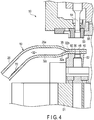
- FIG. 4 shows a part of an apparatus 50 which processes the eye portion 40.
- the apparatus 50 which processes the eye portion 40 includes a lower die 52, an upper die 53, and a punch 54.
- the lower die 52 is arranged on a base 51.
- the upper die 53 is disposed above the lower die 52.
- the punch 54 is movable vertically.
- the terminal sealed portion 30 is pressed between the lower die 52 and the upper die 53.
- the through-hole 48 is formed.
- a peripheral edge of the eye portion 40 is cut by the lower blade 52 and an upper blade 55, trimming is performed.
- the terminal sealed portion 30 is formed. Inside the terminal sealed portion 30, at substantially the center of the terminal sealed portion 30 in a thickness direction, an inner surface joined portion 60 is formed. The inner surface joined portion 60 is formed by press-bonding inner surfaces of the end portion of the flattened hollow rod 20 onto each other.
- the tapered portion 35 is formed between the rod main body 20a which remains intact and the terminal sealed portion 30. The thickness of the tapered portion 35 is reduced from the rod main body 20a to the terminal sealed portion 30.
- a terminal gap 32a of a tapered shape is formed inside the tapered portion 35. In the terminal gap 32a, a gap is reduced toward the inner surface joined portion 60. A farthest end 32b of the terminal gap 32a reaches the inner surface joined portion 60 of the terminal sealed portion 30.
- a similar terminal gap 33a ( FIG. 2 ) is formed.
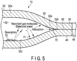
- FIG. 5 is a cross-sectional view schematically showing the terminal sealed portion 30, the tapered portion 35, and the eye portion 40.
- a volatile powdered rust inhibitor 70 is supplied in the enclosed space 32 of the hollow rod 20 in the enclosed space 32 of the hollow rod 20, a volatile powdered rust inhibitor 70 is supplied.
- the volatile powdered rust inhibitor 70 is, for example, a benzoate such as ammonium benzoate, sodium benzoate, or organic amine benzoate.
- As an inorganic ingredient a few percent of oxidized silicon may be included in the volatile powdered rust inhibitor 70 as necessary.
- the volatile powdered rust inhibitor 70 of the present embodiment is comprised of a number of particles. The particles have irregular shapes and irregular sizes. The size of each particle is approximately 10 to 150 ⁇ m.
- a volatile powdered rust inhibitor containing a nitrite such as sodium nitrite as the main ingredient may be used.
- the volatile powdered rust inhibitor 70 of the present embodiment is supplied in an amount sufficient to bring the vaporized component (gas molecules) into a balanced state within the enclosed space 32.
- an amount sufficient to bring the vaporized component (gas molecules) into a balanced state within the enclosed space 32 for example, in the case of a hollow stabilizer having a length of 150 cm, an inner diameter ⁇ of 15 mm, and an internal volume of 265 cc, about 0.2 grams of volatile powdered rust inhibitor 70 is supplied.
- 0.3 to 1.0 gram of the volatile powdered rust inhibitor 70 may be supplied per the internal volume of 1000 cc.
- the volatile powdered rust inhibitor 70 is supplied in an amount of bringing adsorption to and desorption from an inner surface 32c of the enclosed space 32 into balance at a temperature (for example, 0°C or more) of the vehicle surrounding.
- the supplied volatile powdered rust inhibitor 70 sublimes and vaporizes within the enclosed space 32 of the hollow rod 20.
- the gas molecules of the volatile powdered rust inhibitor 70 which have reached a saturation state after vaporization make a rust-inhibiting atmosphere within the enclosed space 32.
- the gas molecules are reversibly adsorbed to the inner surface 32c of the enclosed space 32, that is, the surface of the steel material, physically or chemically.
- the gas molecules of the volatile powdered rust inhibitor 70 enter inside to a point of the farthest end 32b of the terminal gap 32a, and form a terminal rust-inhibiting film 72. Accordingly, formation of rust on the inner surface joined portion 60 of the terminal sealed portion 30 can also be suppressed.
- a small pit or a small crack may be formed on the inner surface of the hollow rod 20 (the inner surface 32c of the enclosed space 32).
- a vaporized component of the volatile powdered rust inhibitor floating within the enclosed space 32 enters inside the small pit or small crack. Consequently, the inner surface rust-inhibiting film 71 and the terminal rust-inhibiting film 72 are formed.
- the stabilizer 10 of the present embodiment by the inner surface rust-inhibiting film 71 and the terminal rust-inhibiting film 72 formed on the inner surface of the hollow rod 20, growth of the small pit and the small crack can be suppressed.
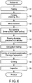
- FIG. 6 is a flowchart showing an example of steps of manufacturing the stabilizer 10 of the present embodiment.
- the hollow rod 20 is heated in heating step S1 in FIG. 6 .
- the heated hollow rod 20 is formed in a predetermined stabilizer shape by a bending machine in forming step S2.
- heat treatment step S3 heat treatment such as quenching and tempering, or annealing for stress relief is performed as necessary.
- heating step S1 can be omitted.
- shot peening step S4 in FIG. 6 shot peening is carried out on the inner surface and the outer surface of the hollow rod 20.
- compressive residual stress is formed on each of the inner surface and the outer surface of the hollow rod 20.
- a reflective member is inserted in the hollow rod 20. Shots are projected at the reflective member.
- shot peening indentations that is, a rough surface 75
- the rough surface 75 is constituted of multiple irregularities. An average surface roughness of the rough surface 75 is, for example, 5 to 6 ⁇ m.
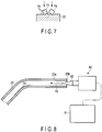
- a powdered rust inhibitor supplying apparatus 80 as shown in FIG. 8 , the volatile powdered rust inhibitor 70 is supplied within the hollow rod 20.
- the terminal sealed portion has not yet been formed in the hollow rod 20. Accordingly, both ends of the hollow rod 20 are open.
- the powdered rust inhibitor supplying apparatus 80 includes a powdered rust inhibitor supply source 81 and a nozzle 82.
- the volatile powdered rust inhibitor 70 is pneumatically transferred from the powdered rust inhibitor supply source 81 toward the nozzle 82 by gas such as air.
- the volatile powdered rust inhibitor 70 jetted out from the nozzle 82 is blown into the hollow rod 20 from an opening 20b on one side of the hollow rod 20.
- volatile powdered rust inhibitor 70 for example, in the case of a hollow stabilizer having the internal volume of 265 cc, about 0.2 grams of volatile powdered rust inhibitor 70 is supplied. If the internal volume is greater than or smaller than the above, the volatile powdered rust inhibitor 70 in an amount according to the internal volume is supplied. The volatile powdered rust inhibitor 70 supplied within the hollow rod 20 does not vaporize immediately, but vaporizes by taking some time. Accordingly, the volatile powdered rust inhibitor 70 can stay inside the hollow rod 20.
- rust inhibitor supplying step S5 a part of the volatile powdered rust inhibitor 70 which has been blown into the hollow rod 20 may adhere to the end portion of the hollow rod 20.
- End portion heating step S6 is carried out after rust inhibitor supplying step S5. Since the end portion of the hollow rod 20 is heated in end portion heating step S6, the volatile powdered rust inhibitor 70 adhering to the end portion of the hollow rod 20 can be removed.
- end portion heating step S6 one of the end portions of the hollow rod 20 is heated to a temperature suitable for forging. Plastic working such as forging is performed for one of the heated end portions by end portion forming step S7.
- the first terminal sealed portion 30 is formed in end portion forming step S7, and the eye portion 40 is also formed.
- the other end portion of the hollow rod 20 is also heated by end portion heating step S6. Plastic working such as forging is performed for the other heated end portion by end portion forming step S7.
- the second terminal sealed portion 31 is formed in end portion forming step S7, and the eye portion 41 is also formed.
- the terminal sealed portions 30 and 31 are formed on both ends of the hollow rod 20. Consequently, the enclosed space 32 is formed inside the hollow rod 20, in other words, between the terminal sealed portions 30 and 31.
- the volatile powdered rust inhibitor 70 trapped in the enclosed space 32 is gradually vaporized within the enclosed space 32.
- the vaporized component gas molecules
- the inner surface rust-inhibiting film 71 is formed. Since the vaporized component also enters inside the terminal gap 32a, the terminal rust-inhibiting film 72 is formed.
- a rust-inhibiting coating is applied to the outer surface of the hollow rod 20 by electrostatic coating, etc. As the applied rust-inhibiting coating is fixed on the outer surface of the hollow rod 20 by a baking step, a coating film is formed. Lastly, quality inspection S9 is carried out and a product (hollow stabilizer) is completed.
- a rough surface (i.e., the shot peening indentations shown in FIG. 7 ) 75 constituted of small irregularities on the inner surface 32c of the enclosed space 32 is formed.
- the component of the volatile powdered rust inhibitor 70 contacts the inner surface 32c, the component of the volatile powdered rust inhibitor 70 is adsorbed to the rough surface 75. More specifically, the small irregularities of the rough surface 75 are covered with the components of the volatile powdered rust inhibitor 70.
- the inner surface rust-inhibiting film 71 can also be formed on the inner surface 32c including the rough surface 75 such as the shot peening indentations without problems. Moreover, since the vaporized component of the volatile powdered rust inhibitor 70 enters inside to the point of the farthest end 32b of the terminal gap 32a, the terminal rust-inhibiting film 72 is formed. Accordingly, formation of rust on the inner surface joined portion 60 can also be prevented.
- FIG. 9 shows a hollow coil spring 90 of a second embodiment.
- the hollow coil spring 90 includes a hollow rod (a hollow wire) 91 made of steel that is formed helically. Both ends of the hollow rod 91 are plastically worked in a temperature range of hot working. By the plastic working, a first terminal sealed portion 92 and a second terminal sealed portion 93 are formed. Accordingly, inside the hollow rod 91, that is, between the first terminal sealed portion 92 and the second terminal sealed portion 93, an enclosed space 94 is formed. A terminal gap 95 is formed on an inner side of the first terminal sealed portion 92 (i.e., one end of the enclosed space 94). A terminal gap 96 is formed on an inner side of the second terminal sealed portion 93 (i.e., the other end of the enclosed space 94).
- a volatile powdered rust inhibitor 70 is supplied in the enclosed space 94 inside the hollow coil spring 90.
- a vaporized component of the volatile powdered rust inhibitor 70 an inner surface rust-inhibiting film 71 is formed on the inner surface of the enclosed space 94.
- the volatile powdered rust inhibitor 70 enters inside the terminal gaps 95 and 96 at the inner side of the terminal sealed portions 92 and 93.
- a terminal rust-inhibiting film 72 is formed by the vaporized component of the volatile powdered rust inhibitor 70 which has entered inside the terminal gaps 95 and 96. By the terminal rust-inhibiting film 72, rusting of the terminal gaps 95 and 96 is prevented.
- FIG. 10 shows an example of steps of manufacturing the hollow coil spring 90.
- rust inhibitor blowing step S10 a volatile powdered rust inhibitor is supplied within the hollow rod 91.
- terminal sealing step S11 both ends of the hollow rod 91 are heated and plastically worked. By the plastic working, the terminal sealed portions 92 and 93 are formed.
- step S12 the hollow rod 91 is formed into a helical shape by a coiling machine, etc.
- shot peening step S13 shot peening is performed on an outer surface of the hollow rod 91.
- coating step S14 coating is applied to the outer surface of the hollow rod 91.
- inspection step S15 inspection is carried out, and a product (the hollow coil spring 90) is completed.
- a heat treatment step for stress relief, a setting step, a step for surface treatment, etc. may be included as necessary.
- the specific forms of the inner surface joined portion of the terminal sealed portion, the terminal gap, and the like may be modified variously.
- a torsion bar, a ring spring, a swirl spring, etc. may be adopted as the hollow spring member, and the elements are not limited to those of the above embodiments.
Landscapes
- Engineering & Computer Science (AREA)
- General Engineering & Computer Science (AREA)
- Mechanical Engineering (AREA)
- Vehicle Body Suspensions (AREA)
- Springs (AREA)
- Fluid-Damping Devices (AREA)
Abstract
Description
- The present invention relates to a hollow spring member such as a hollow stabilizer arranged in a suspension mechanism of a vehicle such as a car, and a method of manufacturing the same.
- A hollow stabilizer arranged in a suspension mechanism of a vehicle is constituted of a hollow rod made of steel (a steel pipe). The hollow stabilizer includes a torsion portion (a twisted portion), and a pair of arm portions (arms). The torsion portion extends in a width direction of the vehicle. The arm portions are extended from both ends of the torsion portion through curved portions, respectively. On a distal end of each of the arm portions, an eye portion is formed. In one example of the stabilizer, the torsion portion is supported on a vehicle body via a support portion, and the eye portion is connected to a suspension arm, etc., via a connecting member. The support portion includes a rubber bushing. One example of the connecting member is a link member (a stabilizer link). With respect to the stabilizer fitted in the suspension mechanism, as the arm portions, the curved portions, and the torsion portion function as a spring in reaction to a rolling behavior of the vehicle body, roll stiffness of the vehicle can be enhanced.
-
Patent Literature 1 or Patent Literature 2 describes an example of a hollow stabilizer. Eye portions are formed on both ends of the hollow stabilizer, respectively. A material of the hollow stabilizer is a hollow rod. By flattening end portions of the hollow rod in a radial direction of the hollow rod by upsetting, the eye portions are formed. In each of the eye portions, a through-hole is formed. A connecting member such as a stabilizer link is inserted into the through-hole. The eye portion is connected to a suspension arm, etc., via the connecting member. -
- Patent Literature 1:
JP H07-237428 A - Patent Literature 2:
JP 2002-331326 A - In order to reduce fuel consumption of a vehicle, or enhance the driving performance, there is an increasing demand for reducing the weight of vehicles. A spring member such as a stabilizer or a coil spring which constitutes the suspension mechanism is not an exception, and reducing the weight is an inevitable requirement. For example, by using a high-strength spring steel for the material of the hollow stabilizer, attempts have been made to reduce the thickness of the hollow stabilizer as much as possible. Further, forming a compressive residual stress by performing shot peening on an inner surface of the hollow stabilizer helps to achieve high-strength in the hollow stabilizer.
- However, with respect to durability of the hollow stabilizer, the smaller the thickness of the hollow stabilizer is, the greater the effect of the rust becomes. For example, rust formed on the outer surface or the inner surface of the hollow stabilizer may cause a small pit. When the pit grows to some degree, the possibility that the pit may become a starting point of a break in the hollow stabilizer which is used under high stress is increased. Accordingly, some preventive measures must be taken against rust which will be formed on the inner surface, in addition to the outer surface, for the hollow stabilizer.
- If a pair of terminal sealed portions is formed by flattening both ends of the hollow rod, an enclosed space is formed between these terminal sealed portions. At an end of the enclosed space, a tapered gap in which the gap is narrowed toward an inner surface joined portion of the terminal sealed portion is formed. In the present specification, the gap is referred to as a terminal gap. When rust is formed on an inner surface of the terminal gap, it is concerned that structural integrity of the terminal sealed portion and the eye portion may be adversely affected.
- The main cause of rust formed on the inner surface of the hollow stabilizer is moisture. For example, when a hollow stabilizer is manufactured, there are cases where moisture inevitably exists inside a hollow rod used as the material of the hollow stabilizer. This moisture becomes a cause of the rust. In order to prevent rust from being formed, applying oil to the inner part of the hollow stabilizer has been considered. However, such oil cannot be adopted since it causes smoke or fire in a heat treatment which is performed in the step of manufacturing the hollow stabilizer. As the other means for rust prevention, applying coating to the inner surface of the hollow stabilizer has been considered. However, there is a problem that drying a coating material applied to the inner surface of the hollow stabilizer takes long time. In addition, if a part of the coating material exists at an end portion of the hollow rod, when the eye portions are formed by flattening the end portions, the coating material remaining at the end portion causes press bonding failure of the terminal sealed portion.
- Accordingly, an object of the present invention is to provide a hollow spring member capable of suppressing formation of rust on an inner surface, etc., of a hollow rod made of steel, and a method of manufacturing the same.
- A hollow spring member according to one embodiment includes a hollow rod formed of a rod-shaped steel material. At both ends of the hollow rod, terminal sealed portions are formed, respectively. An enclosed space is formed between the pair of terminal sealed portions. At an end of the enclosed space, a terminal gap in which the gap is narrowed toward an inner surface joined portion of the terminal sealed portion is formed. Further, the hollow spring member comprises a volatile powdered rust inhibitor supplied in the enclosed space, an inner surface rust-inhibiting film which exists on an inner surface of the enclosed space, and a terminal rust-inhibiting film which exists at the terminal gap. The inner surface rust-inhibiting film exists on the inner surface of the enclosed space as a component of the volatile powdered rust inhibitor which has vaporized within the enclosed space is adsorbed to the inner surface of the enclosed space. The terminal rust-inhibiting film exists in the terminal gap as the vaporized component is adsorbed to an inner surface of the terminal gap. Preferably, the volatile powdered rust inhibitor should be supplied in an amount sufficient for the component which has vaporized in the enclosed space to be saturated in the enclosed space.
- An example of the hollow spring member is a hollow stabilizer constituted of a hollow rod made of steel. The hollow stabilizer includes a torsion portion extending in a width direction of a vehicle, curved portions formed at both ends of the torsion portion, arm portions extended from the curved portions, and the terminal sealed portion formed at a distal end of each of the arm portions. On an inner surface of the hollow spring member, a rough surface (shot peening indentations) constituted of small irregularities may be formed. Another example of the hollow spring member is a hollow coil spring constituted of a hollow rod made of steel that is formed into a helical shape.
- According to the present invention, by a vaporized component of the volatile powdered rust inhibitor supplied in the enclosed space of the hollow rod, the inner surface rust-inhibiting film is formed. By the inner surface rust-inhibiting film, rusting of the inner surface of the enclosed space can be suppressed. Moreover, the terminal rust-inhibiting film is formed as the vaporized component enters inside the terminal gap, and thus, rusting of a part near the terminal gap can also be suppressed.
- When the volatile powdered rust inhibitor is supplied within the hollow rod, the volatile powdered rust inhibitor may adhere to an end portion of the hollow rod. The adhered volatile powdered rust inhibitor is removed as a hollow rod end portion is heated when the terminal sealed portion is plastically worked. Accordingly, it is possible to prevent the volatile powdered rust inhibitor from affecting the joining strength of the terminal sealed portion. Shot peening indentations (i.e., a rough surface) may be formed on the inner surface of the hollow spring member. Since the vaporized component of the volatile powdered rust inhibitor is adsorbed to the rough surface, a rust-inhibiting effect can also be exhibited on a hollow spring material having the shot peening indentations.
-
-
FIG. 1 is a perspective view showing a part of a vehicle and a stabilizer. -
FIG. 2 is a plan view showing an embodiment of a hollow stabilizer. -
FIG. 3 is a plan view of one of eye portions of the hollow stabilizer shown inFIG. 2 . -
FIG. 4 is a cross-sectional view of a part of an apparatus which processes the eye portion of the hollow stabilizer shown inFIG. 2 . -
FIG. 5 is a cross-sectional view which schematically shows a part of the hollow stabilizer shown inFIG. 2 and a volatile powdered rust inhibitor. -
FIG. 6 is a flowchart showing an example of steps of manufacturing the hollow stabilizer shown inFIG. 2 . -
FIG. 7 is a cross-sectional view which schematically shows a part of the hollow stabilizer having shot peening indentations and shots. -
FIG. 8 is an illustration which schematically shows an example of a powdered rust inhibitor supplying apparatus. -
FIG. 9 is a perspective view showing an example of a hollow coil spring. -
FIG. 10 is a flowchart showing an example of steps of manufacturing the hollow coil spring shown inFIG. 9 . - A
hollow stabilizer 10 according to a first embodiment of a hollow spring member, and a method of manufacturing the same will be explained with reference toFIGS. 1 to 8 . -
FIG. 1 shows a part of avehicle 11 comprising the hollow stabilizer 10 (which may hereinafter be simply referred to as a stabilizer 10). Thestabilizer 10 constitutes a part of a suspension mechanism, and is arranged at the lower part of avehicle body 12. -
FIG. 2 is a plan view showing an example of thestabilizer 10. Thestabilizer 10 includes ahollow rod 20. Thehollow rod 20 is made of a rod-shaped steel material, and is formed by a bending machine. An example of the material of thehollow rod 20 is a steel pipe made of spring steel. More specifically, a steel pipe whose strength can be improved by a heat treatment such as quenching is used. Although the type of spring steel is not particularly limited, SAE1022, which is the steel defined by the American Society of Automotive Engineers, for example, may be used. The chemical components of SAE1022 are Fe as the main component, 0.17-0.23 wt% of C, 0.70-1.00 wt% of Mn, and a small amount of Si, P, S, etc., as the remainder. As another example of the spring steel, a high-strength steel may be adopted. As an example, the chemical components (mass %) of a high-strength spring are C:0.40; Si:1.8; Mn:0.3; Cr:1.05; P:0.01; S:0.005; Ni:0.4; Cu:0.25; V:0.18; Ti:0.07; and Fe:the remainder. - The
hollow rod 20 is bisymmetrical with respect to a symmetric axis X1 (FIG. 2 ). More specifically, thehollow rod 20 includes atorsion portion 25,curved portions arm portions torsion portion 25 extends in a width direction of thevehicle body 12. A direction indicated by arrow W1 inFIG. 1 is the width direction of thevehicle body 12. Thearm portions torsion portion 25 through thecurved portions hollow rod 20. - The shape of the
stabilizer 10 is not limited to planar. Thestabilizer 10 may include one or more bending portions in thetorsion portion 25, or one or more bending portions in thearm portions curved portions - On one end portion of the
hollow rod 20, a first terminal sealedportion 30 is formed. On the other end portion of thehollow rod 20, a second terminal sealedportion 31 is formed. These terminal sealedportions hollow rod 20 in a radial direction. For example, as both ends of thehollow rod 20 are flattened by plastic working such as forging, the terminal sealedportions hollow rod 20, that is, between the first terminal sealedportion 30 and the second terminal sealedportion 31, anenclosed space 32 is formed. - In the present specification, of the entire
hollow rod 20, a part which remains intact without being flattened, existing between the terminal sealedportions main body 20a.Tapered portions main body 20a and the terminal sealedportion 30, and between the rodmain body 20a and the terminal sealedportion 31, respectively. Thetapered portions main body 20a to the terminal sealedportions -
Eye portions portions eye portions members torsion portion 25 is supported by a part of thevehicle body 12, for example, via a pair ofsupport portions 45 and 46 (FIG. 1 ). Thesupport portions arm portions vehicle 11 drives on a curve, for example. By this input of force, a bending force is exerted on thearm portions curved portions torsion portion 25 being twisted, a rolling behavior of thevehicle body 12 is suppressed. -
FIG. 3 shows the first terminal sealedportion 30 and theeye portion 40. The second terminal sealedportion 31 and the eye portion 41 (FIG. 2 ) are shaped similarly. In the following, the first terminal sealedportion 30 and theeye portion 40 will be described as a typical example of the terminal sealed portion and the eye portion. A circular through-hole 48 is formed in theeye portion 40. The connectingmember 42 such as a stabilizer link is inserted into the through-hole 48. -
FIG. 4 shows a part of anapparatus 50 which processes theeye portion 40. Theapparatus 50 which processes theeye portion 40 includes alower die 52, anupper die 53, and apunch 54. Thelower die 52 is arranged on abase 51. Theupper die 53 is disposed above thelower die 52. Thepunch 54 is movable vertically. The terminal sealedportion 30 is pressed between thelower die 52 and theupper die 53. As thepunch 54 is lowered in this pressurized state, the through-hole 48 is formed. As a peripheral edge of theeye portion 40 is cut by thelower blade 52 and anupper blade 55, trimming is performed. - By flattening the end portion of the
hollow rod 20 in the radial direction as described above, the terminal sealedportion 30 is formed. Inside the terminal sealedportion 30, at substantially the center of the terminal sealedportion 30 in a thickness direction, an inner surface joinedportion 60 is formed. The inner surface joinedportion 60 is formed by press-bonding inner surfaces of the end portion of the flattenedhollow rod 20 onto each other. The taperedportion 35 is formed between the rodmain body 20a which remains intact and the terminal sealedportion 30. The thickness of the taperedportion 35 is reduced from the rodmain body 20a to the terminal sealedportion 30. Inside the taperedportion 35, at an end of the enclosedspace 32, aterminal gap 32a of a tapered shape is formed. In theterminal gap 32a, a gap is reduced toward the inner surface joinedportion 60. Afarthest end 32b of theterminal gap 32a reaches the inner surface joinedportion 60 of the terminal sealedportion 30. Also in the terminal sealedportion 31 on the other side, a similar terminal gap 33a (FIG. 2 ) is formed. -
FIG. 5 is a cross-sectional view schematically showing the terminal sealedportion 30, the taperedportion 35, and theeye portion 40. In theenclosed space 32 of thehollow rod 20, a volatilepowdered rust inhibitor 70 is supplied. The volatilepowdered rust inhibitor 70 is, for example, a benzoate such as ammonium benzoate, sodium benzoate, or organic amine benzoate. As an inorganic ingredient, a few percent of oxidized silicon may be included in the volatilepowdered rust inhibitor 70 as necessary. The volatilepowdered rust inhibitor 70 of the present embodiment is comprised of a number of particles. The particles have irregular shapes and irregular sizes. The size of each particle is approximately 10 to 150 µm. As another example, a volatile powdered rust inhibitor containing a nitrite such as sodium nitrite as the main ingredient may be used. - The volatile
powdered rust inhibitor 70 of the present embodiment is supplied in an amount sufficient to bring the vaporized component (gas molecules) into a balanced state within the enclosedspace 32. For example, in the case of a hollow stabilizer having a length of 150 cm, an inner diameter φ of 15 mm, and an internal volume of 265 cc, about 0.2 grams of volatilepowdered rust inhibitor 70 is supplied. According to the component of the volatilepowdered rust inhibitor 70 or the type of steel of thehollow rod 20, 0.3 to 1.0 gram of the volatilepowdered rust inhibitor 70 may be supplied per the internal volume of 1000 cc. - The volatile
powdered rust inhibitor 70 is supplied in an amount of bringing adsorption to and desorption from aninner surface 32c of the enclosedspace 32 into balance at a temperature (for example, 0°C or more) of the vehicle surrounding. The supplied volatilepowdered rust inhibitor 70 sublimes and vaporizes within the enclosedspace 32 of thehollow rod 20. The gas molecules of the volatilepowdered rust inhibitor 70 which have reached a saturation state after vaporization make a rust-inhibiting atmosphere within the enclosedspace 32. The gas molecules are reversibly adsorbed to theinner surface 32c of the enclosedspace 32, that is, the surface of the steel material, physically or chemically. By this adsorption, an extremely thin inner surface rust-inhibitingfilm 71 of 10Å or so, for example, is formed on theinner surface 32c of the enclosedspace 32. By the inner surface rust-inhibitingfilm 71, it is possible to prevent rust from being formed on theinner surface 32c of the enclosedspace 32. The gas molecules of the volatilepowdered rust inhibitor 70 enter inside to a point of thefarthest end 32b of theterminal gap 32a, and form a terminal rust-inhibitingfilm 72. Accordingly, formation of rust on the inner surface joinedportion 60 of the terminal sealedportion 30 can also be suppressed. - Stress is applied repeatedly to the
stabilizer 10 while the vehicle is moving. If some other factors come into play in addition to the above stress, a small pit or a small crack may be formed on the inner surface of the hollow rod 20 (theinner surface 32c of the enclosed space 32). When small pits or small cracks start to form on the inner surface of thehollow rod 20, a vaporized component of the volatile powdered rust inhibitor floating within the enclosedspace 32 enters inside the small pit or small crack. Consequently, the inner surface rust-inhibitingfilm 71 and the terminal rust-inhibitingfilm 72 are formed. According to thestabilizer 10 of the present embodiment, by the inner surface rust-inhibitingfilm 71 and the terminal rust-inhibitingfilm 72 formed on the inner surface of thehollow rod 20, growth of the small pit and the small crack can be suppressed. -
FIG. 6 is a flowchart showing an example of steps of manufacturing thestabilizer 10 of the present embodiment. For example, when thestabilizer 10 is formed by hot working (for example, in a temperature range in which steel is austenitized), thehollow rod 20 is heated in heating step S1 inFIG. 6 . The heatedhollow rod 20 is formed in a predetermined stabilizer shape by a bending machine in forming step S2. In heat treatment step S3, heat treatment such as quenching and tempering, or annealing for stress relief is performed as necessary. When thestabilizer 10 is to be formed by cold working (for example, at room temperature), heating step S1 can be omitted. - In shot peening step S4 in
FIG. 6 , shot peening is carried out on the inner surface and the outer surface of thehollow rod 20. By the shot peening, compressive residual stress is formed on each of the inner surface and the outer surface of thehollow rod 20. When the shot peening is performed on the inner surface of thehollow rod 20, a reflective member is inserted in thehollow rod 20. Shots are projected at the reflective member. In this way, shot peening indentations, that is, arough surface 75, is formed on the inner surface of thehollow rod 20 as schematically shown inFIG. 7 . Therough surface 75 is constituted of multiple irregularities. An average surface roughness of therough surface 75 is, for example, 5 to 6 µm. - In rust inhibitor supplying step S5 in
FIG. 6 , by a powdered rustinhibitor supplying apparatus 80 as shown inFIG. 8 , the volatilepowdered rust inhibitor 70 is supplied within thehollow rod 20. In rust inhibitor supplying step S5, the terminal sealed portion has not yet been formed in thehollow rod 20. Accordingly, both ends of thehollow rod 20 are open. The powdered rustinhibitor supplying apparatus 80 includes a powdered rustinhibitor supply source 81 and anozzle 82. The volatilepowdered rust inhibitor 70 is pneumatically transferred from the powdered rustinhibitor supply source 81 toward thenozzle 82 by gas such as air. The volatilepowdered rust inhibitor 70 jetted out from thenozzle 82 is blown into thehollow rod 20 from anopening 20b on one side of thehollow rod 20. - For example, in the case of a hollow stabilizer having the internal volume of 265 cc, about 0.2 grams of volatile
powdered rust inhibitor 70 is supplied. If the internal volume is greater than or smaller than the above, the volatilepowdered rust inhibitor 70 in an amount according to the internal volume is supplied. The volatilepowdered rust inhibitor 70 supplied within thehollow rod 20 does not vaporize immediately, but vaporizes by taking some time. Accordingly, the volatilepowdered rust inhibitor 70 can stay inside thehollow rod 20. - In rust inhibitor supplying step S5, a part of the volatile
powdered rust inhibitor 70 which has been blown into thehollow rod 20 may adhere to the end portion of thehollow rod 20. End portion heating step S6 is carried out after rust inhibitor supplying step S5. Since the end portion of thehollow rod 20 is heated in end portion heating step S6, the volatilepowdered rust inhibitor 70 adhering to the end portion of thehollow rod 20 can be removed. - In end portion heating step S6, one of the end portions of the
hollow rod 20 is heated to a temperature suitable for forging. Plastic working such as forging is performed for one of the heated end portions by end portion forming step S7. The first terminal sealedportion 30 is formed in end portion forming step S7, and theeye portion 40 is also formed. The other end portion of thehollow rod 20 is also heated by end portion heating step S6. Plastic working such as forging is performed for the other heated end portion by end portion forming step S7. The second terminal sealedportion 31 is formed in end portion forming step S7, and theeye portion 41 is also formed. - In this way, the terminal sealed
portions hollow rod 20. Consequently, theenclosed space 32 is formed inside thehollow rod 20, in other words, between the terminal sealedportions powdered rust inhibitor 70 trapped in the enclosedspace 32 is gradually vaporized within the enclosedspace 32. As the vaporized component (gas molecules) is adsorbed to the inner surface of the enclosedspace 32, the inner surface rust-inhibitingfilm 71 is formed. Since the vaporized component also enters inside theterminal gap 32a, the terminal rust-inhibitingfilm 72 is formed. - In coating step S8, a rust-inhibiting coating is applied to the outer surface of the
hollow rod 20 by electrostatic coating, etc. As the applied rust-inhibiting coating is fixed on the outer surface of thehollow rod 20 by a baking step, a coating film is formed. Lastly, quality inspection S9 is carried out and a product (hollow stabilizer) is completed. - In the case of a hollow stabilizer which is used under high stress for weight reduction, it is common to perform shot peening on the outer surface of the
hollow rod 20 and theinner surface 32c of the enclosedspace 32. In that case, a rough surface (i.e., the shot peening indentations shown inFIG. 7 ) 75 constituted of small irregularities on theinner surface 32c of the enclosedspace 32 is formed. As the vaporized component of the volatilepowdered rust inhibitor 70 contacts theinner surface 32c, the component of the volatilepowdered rust inhibitor 70 is adsorbed to therough surface 75. More specifically, the small irregularities of therough surface 75 are covered with the components of the volatilepowdered rust inhibitor 70. Accordingly, the inner surface rust-inhibitingfilm 71 can also be formed on theinner surface 32c including therough surface 75 such as the shot peening indentations without problems. Moreover, since the vaporized component of the volatilepowdered rust inhibitor 70 enters inside to the point of thefarthest end 32b of theterminal gap 32a, the terminal rust-inhibitingfilm 72 is formed. Accordingly, formation of rust on the inner surface joinedportion 60 can also be prevented. -
FIG. 9 shows ahollow coil spring 90 of a second embodiment. Thehollow coil spring 90 includes a hollow rod (a hollow wire) 91 made of steel that is formed helically. Both ends of thehollow rod 91 are plastically worked in a temperature range of hot working. By the plastic working, a first terminal sealedportion 92 and a second terminal sealedportion 93 are formed. Accordingly, inside thehollow rod 91, that is, between the first terminal sealedportion 92 and the second terminal sealedportion 93, anenclosed space 94 is formed. Aterminal gap 95 is formed on an inner side of the first terminal sealed portion 92 (i.e., one end of the enclosed space 94). Aterminal gap 96 is formed on an inner side of the second terminal sealed portion 93 (i.e., the other end of the enclosed space 94). - Similarly to the
hollow stabilizer 10 of the first embodiment, a volatilepowdered rust inhibitor 70 is supplied in the enclosedspace 94 inside thehollow coil spring 90. By a vaporized component of the volatilepowdered rust inhibitor 70, an inner surface rust-inhibitingfilm 71 is formed on the inner surface of the enclosedspace 94. By the inner surface rust-inhibitingfilm 71, rusting on an inner surface of thehollow rod 91 is suppressed. Also, the volatilepowdered rust inhibitor 70 enters inside theterminal gaps portions film 72 is formed by the vaporized component of the volatilepowdered rust inhibitor 70 which has entered inside theterminal gaps film 72, rusting of theterminal gaps -
FIG. 10 shows an example of steps of manufacturing thehollow coil spring 90. In rust inhibitor blowing step S10, a volatile powdered rust inhibitor is supplied within thehollow rod 91. In terminal sealing step S11, both ends of thehollow rod 91 are heated and plastically worked. By the plastic working, the terminal sealedportions hollow rod 91 is formed into a helical shape by a coiling machine, etc. In a shot peening step S13, shot peening is performed on an outer surface of thehollow rod 91. In a coating step S14, coating is applied to the outer surface of thehollow rod 91. In inspection step S15, inspection is carried out, and a product (the hollow coil spring 90) is completed. In the steps of manufacturing a coil spring, a heat treatment step for stress relief, a setting step, a step for surface treatment, etc., may be included as necessary. - Needless to say, in carrying out the present invention, the specific forms of the inner surface joined portion of the terminal sealed portion, the terminal gap, and the like, may be modified variously. Further, other than the hollow stabilizer and the hollow coil spring explained in the above embodiments, a torsion bar, a ring spring, a swirl spring, etc., may be adopted as the hollow spring member, and the elements are not limited to those of the above embodiments.
- 10···Hollow stabilizer (hollow spring member), 20···Hollow rod, 20a···Rod main body, 25···Torsion portion, 26, 27···Curved portions, 28, 29···Arm portions, 30, 31···Terminal sealed portions, 32···Enclosed space, 32a···Terminal gap, 32b···Farthest end, 32c···Inner surface, 35, 36···Tapered portions, 40, 41···Eye portions, 60···Inner surface joined portion, 70···Volatile powdered rust inhibitor, 71···Inner surface rust-inhibiting film, 72···Terminal rust-inhibiting film, 75···Rough surface (shot peening indentations), 80···Powdered rust inhibitor supplying apparatus, 90···Hollow coil spring (hollow spring member), 91···Hollow rod, 92, 93···Terminal sealed portions, 94···Enclosed space, 95, 96···Terminal gaps
Claims (6)
- A hollow spring member characterized by comprising:a hollow rod (20) (91) being formed of a rod-shaped steel material, and including: terminal sealed portions (30, 31) (92, 93) at both ends of the hollow rod (20) (91); an enclosed space (32) (94) between the terminal sealed portions (30, 31) (92, 93); and terminal gaps (32a, 33a) (95, 96) in which a gap is narrowed toward an inner surface joined portion (60) of the terminal sealed portions (30, 31) (92, 93) at respective ends of the enclosed space (32) (94);a volatile powdered rust inhibitor (70) supplied in the enclosed space (32) (94);an inner surface rust-inhibiting film (71) which exists on an inner surface of the enclosed space (32) (94) in a state in which a component of the volatile powdered rust inhibitor (70) vaporized within the enclosed space (32) (94) is adsorbed to the inner surface of the enclosed space (32) (94); anda terminal rust-inhibiting film (72) which exists at the terminal gaps (32a, 33a) (95, 96) in a state in which the vaporized component is adsorbed to an inner surface of the terminal gaps (32a, 33a) (95, 96).
- The hollow spring member of Claim 1, wherein the volatile powdered rust inhibitor (70) is supplied in an amount sufficient for the component vaporized in the enclosed space (32) (94) to be saturated in the enclosed space (32) (94).
- The hollow spring member of Claim 1, wherein the hollow spring member is a hollow stabilizer (10) including a torsion portion (25) extending in a width direction of a vehicle, curved portions (26, 27) formed at both ends of the torsion portion (25), arm portions (28, 29) extends from the curved portions (26, 27), and the terminal sealed portions (30, 31) formed at distal ends of the arm portions (28, 29).
- The hollow spring member of Claim 3, wherein the hollow spring member includes a rough surface (75) constituted of small irregularities on an inner surface of the hollow rod (20).
- The hollow spring member of Claim 1, wherein the hollow spring member is a hollow coil spring (90) constituted of a hollow rod (91) of a helical shape.
- A method of manufacturing a hollow spring member characterized by comprising:blowing a volatile powdered rust inhibitor (70) from one opening (20b) of a hollow rod (20) made of steel whose ends are open;heating one end portion of the hollow rod (20);forming a first terminal sealed portion (30) by plastically working the heated one end portion;heating the other end portion of the hollow rod (20) ;forming a second terminal sealed portion (31) by plastically working the heated other end portion, and also forming an enclosed space (32) inside the hollow rod (20);bending the hollow rod (20);vaporizing a component of the volatile powdered rust inhibitor (70) within the enclosed space (32); andforming an inner surface rust-inhibiting film (71) on an inner surface of the enclosed space (32) by adsorption of the vaporized component of the volatile powdered rust inhibitor (70) to an inner surface of the enclosed space (32), and forming a terminal rust-inhibiting film (72) by causing the vaporized component to enter inside a terminal gap (32a) of the first terminal sealed portion (30), and a terminal gap (33a) of the second terminal sealed portion (31).
Applications Claiming Priority (2)
| Application Number | Priority Date | Filing Date | Title |
|---|---|---|---|
| JP2016068060 | 2016-03-30 | ||
| PCT/JP2017/013094 WO2017170787A1 (en) | 2016-03-30 | 2017-03-29 | Hollow spring member and manufacturing method therefor |
Publications (3)
| Publication Number | Publication Date |
|---|---|
| EP3438493A1 true EP3438493A1 (en) | 2019-02-06 |
| EP3438493A4 EP3438493A4 (en) | 2019-11-27 |
| EP3438493B1 EP3438493B1 (en) | 2021-03-03 |
Family
ID=59964732
Family Applications (1)
| Application Number | Title | Priority Date | Filing Date |
|---|---|---|---|
| EP17775321.7A Active EP3438493B1 (en) | 2016-03-30 | 2017-03-29 | Hollow spring member and manufacturing method therefor |
Country Status (7)
| Country | Link |
|---|---|
| US (1) | US11285776B2 (en) |
| EP (1) | EP3438493B1 (en) |
| JP (1) | JP6600409B2 (en) |
| CN (1) | CN108884892B (en) |
| HU (1) | HUE054018T2 (en) |
| MX (1) | MX392927B (en) |
| WO (1) | WO2017170787A1 (en) |
Families Citing this family (9)
| Publication number | Priority date | Publication date | Assignee | Title |
|---|---|---|---|---|
| WO2017170789A1 (en) * | 2016-03-30 | 2017-10-05 | 日本発條株式会社 | Hollow coil spring, and suspension device for vehicle |
| CN109154346B (en) | 2016-03-30 | 2020-08-14 | 日本发条株式会社 | hollow spring member |
| JP7154043B2 (en) * | 2018-06-12 | 2022-10-17 | 日本発條株式会社 | stabilizer |
| CN110103663A (en) * | 2019-05-20 | 2019-08-09 | 天津市大港汽车配件弹簧厂 | The automobile transverse direction hollow stabilizing rod and its forming method of sealing two ends |
| CN111496540B (en) * | 2020-03-30 | 2021-11-09 | 永嘉县三和弹簧有限公司 | Spring processing method |
| JP7413341B2 (en) * | 2021-12-24 | 2024-01-15 | 日本発條株式会社 | Stabilizer manufacturing method |
| JP2024054701A (en) | 2022-10-05 | 2024-04-17 | 日本発條株式会社 | Method for rust prevention treatment of cylindrical member |
| DE102023134287B3 (en) * | 2023-12-07 | 2025-04-03 | Thyssenkrupp AG | Pipe stabilizer |
| DE102023134285A1 (en) * | 2023-12-07 | 2025-06-12 | Thyssenkrupp Ag | stabilizer |
Family Cites Families (26)
| Publication number | Priority date | Publication date | Assignee | Title |
|---|---|---|---|---|
| US2643177A (en) * | 1946-05-07 | 1953-06-23 | Shell Dev | Vapor phase corrosion inhibition of metals |
| US3876553A (en) * | 1972-07-03 | 1975-04-08 | Chem Paint Specialties Inc | Corrosion inhibitor containing sodium benzoate and potassium tripolyphosphate |
| JPS4983454U (en) * | 1972-11-07 | 1974-07-19 | ||
| US3901836A (en) * | 1973-10-04 | 1975-08-26 | Chem Paint Specialties Inc | Rust preventative coating for metallic surfaces consisting of water-soluble resin and sodium benzoate-potassium tripolyphosphate rust inhibitor |
| JPS58188532A (en) * | 1982-04-28 | 1983-11-04 | Nhk Spring Co Ltd | Manufacture of hollow stabilizer |
| JPS5913082A (en) * | 1982-07-14 | 1984-01-23 | Nippon Boshoku Kogyo Kk | Method for preventing corrosion of outside surface of bottom plate of outdoor ground tank |
| US4469469A (en) * | 1982-09-13 | 1984-09-04 | The Trenton Corporation | Protective system for underground pipes |
| JPS5997758A (en) * | 1982-11-29 | 1984-06-05 | Kenji Kondo | Soldering device provided with changer for traveling direction of carrier |
| JPS5997758U (en) * | 1982-12-23 | 1984-07-02 | 株式会社東芝 | sprayer |
| JPS6020404A (en) * | 1983-07-13 | 1985-02-01 | 日立照明株式会社 | Linear tubular cord handing implement |
| JPS6020404U (en) * | 1983-07-20 | 1985-02-13 | 横浜機工株式会社 | stabilizer |
| JPH02283519A (en) * | 1989-04-24 | 1990-11-21 | Nhk Spring Co Ltd | Hollow stabilizer for vehicle |
| US5266104A (en) * | 1991-05-08 | 1993-11-30 | Vincent Larry W | Thread protection system |
| US5352383A (en) * | 1991-10-18 | 1994-10-04 | Centrax International Corp. | Corrosion inhibitor and sealable thread protector end cap for tubular goods |
| JP2618159B2 (en) * | 1992-07-31 | 1997-06-11 | 日本発条株式会社 | Hollow torsion bar |
| JP3168236B2 (en) | 1994-02-28 | 2001-05-21 | 日本発条株式会社 | Hollow stabilizer for vehicles and method of manufacturing the same |
| DE19604286C1 (en) * | 1996-02-07 | 1997-07-24 | Benteler Werke Ag | Twist beam axle for motor vehicles |
| JP4042953B2 (en) * | 1999-06-08 | 2008-02-06 | 日本発条株式会社 | Spring for automobile suspension and manufacturing method thereof |
| JP2002331326A (en) * | 2001-03-08 | 2002-11-19 | Nhk Spring Co Ltd | Hollow stabilizer and method of manufacturing the same |
| US20050011592A1 (en) * | 2001-11-30 | 2005-01-20 | Smith James B. | Stabilizer bar |
| CN1241795C (en) * | 2003-01-27 | 2006-02-15 | 卢雄文 | Hollow antisepsis container and its mfg. method |
| JP4907054B2 (en) * | 2003-12-09 | 2012-03-28 | 中央発條株式会社 | High durability spring and its coating method |
| JP2006335119A (en) * | 2005-05-31 | 2006-12-14 | Nissan Motor Co Ltd | Stabilizer support structure |
| DE102005029540A1 (en) * | 2005-06-25 | 2007-01-04 | Daimlerchrysler Ag | vehicle axle |
| JP2007320344A (en) * | 2006-05-30 | 2007-12-13 | Mitsubishi Steel Mfg Co Ltd | Hollow stabilizer |
| US8800224B1 (en) * | 2006-11-14 | 2014-08-12 | Cortec Corporation | Corrosion inhibiting vapor for use in connection with encased articles |
-
2017
- 2017-03-29 EP EP17775321.7A patent/EP3438493B1/en active Active
- 2017-03-29 CN CN201780018654.9A patent/CN108884892B/en active Active
- 2017-03-29 JP JP2018509392A patent/JP6600409B2/en active Active
- 2017-03-29 MX MX2018011708A patent/MX392927B/en unknown
- 2017-03-29 HU HUE17775321A patent/HUE054018T2/en unknown
- 2017-03-29 WO PCT/JP2017/013094 patent/WO2017170787A1/en not_active Ceased
-
2018
- 2018-09-28 US US16/146,269 patent/US11285776B2/en active Active
Also Published As
| Publication number | Publication date |
|---|---|
| WO2017170787A1 (en) | 2017-10-05 |
| EP3438493B1 (en) | 2021-03-03 |
| US20190030980A1 (en) | 2019-01-31 |
| MX2018011708A (en) | 2018-12-19 |
| CN108884892A (en) | 2018-11-23 |
| CN108884892B (en) | 2021-03-09 |
| MX392927B (en) | 2025-03-24 |
| US11285776B2 (en) | 2022-03-29 |
| EP3438493A4 (en) | 2019-11-27 |
| JP6600409B2 (en) | 2019-10-30 |
| JPWO2017170787A1 (en) | 2018-10-25 |
| HUE054018T2 (en) | 2021-08-30 |
Similar Documents
| Publication | Publication Date | Title |
|---|---|---|
| EP3438493B1 (en) | Hollow spring member and manufacturing method therefor | |
| EP3222872B1 (en) | Leaf spring device and method for manufacturing leaf spring device | |
| CN104936803B (en) | Suspension device and compression coil spring for suspension device | |
| JP2002331326A (en) | Hollow stabilizer and method of manufacturing the same | |
| WO2010146898A1 (en) | Vehicle suspension coil spring and method for manufacturing same | |
| KR101075323B1 (en) | Manufacturing method of coil spring using helicoid reduction mill | |
| CN105452705B (en) | coil spring for suspension | |
| US11701943B2 (en) | Method of manufacturing a hollow spring member | |
| US6852181B2 (en) | Flattened U-bolt and method | |
| JP2618159B2 (en) | Hollow torsion bar | |
| WO2010146907A1 (en) | Method for manufacturing coil spring | |
| US11571943B2 (en) | Hollow stabilizer, stabilizer manufacturing device, and method for manufacturing hollow stabilizer | |
| JP5450041B2 (en) | Leaf spring device having eyeball part, method for manufacturing leaf spring device, and shot peening device | |
| JP2007320344A (en) | Hollow stabilizer | |
| EP4417445B1 (en) | Hollow Stabilizer | |
| EP3998171B1 (en) | Stabilizer and method for manufacturing stabilizer |
Legal Events
| Date | Code | Title | Description |
|---|---|---|---|
| STAA | Information on the status of an ep patent application or granted ep patent |
Free format text: STATUS: THE INTERNATIONAL PUBLICATION HAS BEEN MADE |
|
| PUAI | Public reference made under article 153(3) epc to a published international application that has entered the european phase |
Free format text: ORIGINAL CODE: 0009012 |
|
| STAA | Information on the status of an ep patent application or granted ep patent |
Free format text: STATUS: REQUEST FOR EXAMINATION WAS MADE |
|
| 17P | Request for examination filed |
Effective date: 20180928 |
|
| AK | Designated contracting states |
Kind code of ref document: A1 Designated state(s): AL AT BE BG CH CY CZ DE DK EE ES FI FR GB GR HR HU IE IS IT LI LT LU LV MC MK MT NL NO PL PT RO RS SE SI SK SM TR |
|
| AX | Request for extension of the european patent |
Extension state: BA ME |
|
| DAV | Request for validation of the european patent (deleted) | ||
| DAX | Request for extension of the european patent (deleted) | ||
| A4 | Supplementary search report drawn up and despatched |
Effective date: 20191029 |
|
| RIC1 | Information provided on ipc code assigned before grant |
Ipc: F16F 1/02 20060101AFI20191023BHEP Ipc: F16F 1/04 20060101ALI20191023BHEP Ipc: B60G 21/055 20060101ALI20191023BHEP Ipc: F16F 1/14 20060101ALI20191023BHEP |
|
| GRAP | Despatch of communication of intention to grant a patent |
Free format text: ORIGINAL CODE: EPIDOSNIGR1 |
|
| STAA | Information on the status of an ep patent application or granted ep patent |
Free format text: STATUS: GRANT OF PATENT IS INTENDED |
|
| INTG | Intention to grant announced |
Effective date: 20201015 |
|
| GRAS | Grant fee paid |
Free format text: ORIGINAL CODE: EPIDOSNIGR3 |
|
| GRAA | (expected) grant |
Free format text: ORIGINAL CODE: 0009210 |
|
| STAA | Information on the status of an ep patent application or granted ep patent |
Free format text: STATUS: THE PATENT HAS BEEN GRANTED |
|
| AK | Designated contracting states |
Kind code of ref document: B1 Designated state(s): AL AT BE BG CH CY CZ DE DK EE ES FI FR GB GR HR HU IE IS IT LI LT LU LV MC MK MT NL NO PL PT RO RS SE SI SK SM TR |
|
| REG | Reference to a national code |
Ref country code: GB Ref legal event code: FG4D |
|
| REG | Reference to a national code |
Ref country code: AT Ref legal event code: REF Ref document number: 1367550 Country of ref document: AT Kind code of ref document: T Effective date: 20210315 Ref country code: CH Ref legal event code: EP |
|
| REG | Reference to a national code |
Ref country code: DE Ref legal event code: R096 Ref document number: 602017033892 Country of ref document: DE |
|
| REG | Reference to a national code |
Ref country code: IE Ref legal event code: FG4D |
|
| REG | Reference to a national code |
Ref country code: LT Ref legal event code: MG9D |
|
| PG25 | Lapsed in a contracting state [announced via postgrant information from national office to epo] |
Ref country code: BG Free format text: LAPSE BECAUSE OF FAILURE TO SUBMIT A TRANSLATION OF THE DESCRIPTION OR TO PAY THE FEE WITHIN THE PRESCRIBED TIME-LIMIT Effective date: 20210603 Ref country code: LT Free format text: LAPSE BECAUSE OF FAILURE TO SUBMIT A TRANSLATION OF THE DESCRIPTION OR TO PAY THE FEE WITHIN THE PRESCRIBED TIME-LIMIT Effective date: 20210303 Ref country code: FI Free format text: LAPSE BECAUSE OF FAILURE TO SUBMIT A TRANSLATION OF THE DESCRIPTION OR TO PAY THE FEE WITHIN THE PRESCRIBED TIME-LIMIT Effective date: 20210303 Ref country code: GR Free format text: LAPSE BECAUSE OF FAILURE TO SUBMIT A TRANSLATION OF THE DESCRIPTION OR TO PAY THE FEE WITHIN THE PRESCRIBED TIME-LIMIT Effective date: 20210604 Ref country code: HR Free format text: LAPSE BECAUSE OF FAILURE TO SUBMIT A TRANSLATION OF THE DESCRIPTION OR TO PAY THE FEE WITHIN THE PRESCRIBED TIME-LIMIT Effective date: 20210303 Ref country code: NO Free format text: LAPSE BECAUSE OF FAILURE TO SUBMIT A TRANSLATION OF THE DESCRIPTION OR TO PAY THE FEE WITHIN THE PRESCRIBED TIME-LIMIT Effective date: 20210603 |
|
| REG | Reference to a national code |
Ref country code: NL Ref legal event code: MP Effective date: 20210303 |
|
| REG | Reference to a national code |
Ref country code: AT Ref legal event code: MK05 Ref document number: 1367550 Country of ref document: AT Kind code of ref document: T Effective date: 20210303 |
|
| REG | Reference to a national code |
Ref country code: HU Ref legal event code: AG4A Ref document number: E054018 Country of ref document: HU |
|
| PG25 | Lapsed in a contracting state [announced via postgrant information from national office to epo] |
Ref country code: SE Free format text: LAPSE BECAUSE OF FAILURE TO SUBMIT A TRANSLATION OF THE DESCRIPTION OR TO PAY THE FEE WITHIN THE PRESCRIBED TIME-LIMIT Effective date: 20210303 Ref country code: PL Free format text: LAPSE BECAUSE OF FAILURE TO SUBMIT A TRANSLATION OF THE DESCRIPTION OR TO PAY THE FEE WITHIN THE PRESCRIBED TIME-LIMIT Effective date: 20210303 Ref country code: LV Free format text: LAPSE BECAUSE OF FAILURE TO SUBMIT A TRANSLATION OF THE DESCRIPTION OR TO PAY THE FEE WITHIN THE PRESCRIBED TIME-LIMIT Effective date: 20210303 Ref country code: RS Free format text: LAPSE BECAUSE OF FAILURE TO SUBMIT A TRANSLATION OF THE DESCRIPTION OR TO PAY THE FEE WITHIN THE PRESCRIBED TIME-LIMIT Effective date: 20210303 |
|
| PG25 | Lapsed in a contracting state [announced via postgrant information from national office to epo] |
Ref country code: NL Free format text: LAPSE BECAUSE OF FAILURE TO SUBMIT A TRANSLATION OF THE DESCRIPTION OR TO PAY THE FEE WITHIN THE PRESCRIBED TIME-LIMIT Effective date: 20210303 |
|
| PG25 | Lapsed in a contracting state [announced via postgrant information from national office to epo] |
Ref country code: SM Free format text: LAPSE BECAUSE OF FAILURE TO SUBMIT A TRANSLATION OF THE DESCRIPTION OR TO PAY THE FEE WITHIN THE PRESCRIBED TIME-LIMIT Effective date: 20210303 Ref country code: AT Free format text: LAPSE BECAUSE OF FAILURE TO SUBMIT A TRANSLATION OF THE DESCRIPTION OR TO PAY THE FEE WITHIN THE PRESCRIBED TIME-LIMIT Effective date: 20210303 Ref country code: EE Free format text: LAPSE BECAUSE OF FAILURE TO SUBMIT A TRANSLATION OF THE DESCRIPTION OR TO PAY THE FEE WITHIN THE PRESCRIBED TIME-LIMIT Effective date: 20210303 Ref country code: CZ Free format text: LAPSE BECAUSE OF FAILURE TO SUBMIT A TRANSLATION OF THE DESCRIPTION OR TO PAY THE FEE WITHIN THE PRESCRIBED TIME-LIMIT Effective date: 20210303 |
|
| REG | Reference to a national code |
Ref country code: CH Ref legal event code: PL |
|
| PG25 | Lapsed in a contracting state [announced via postgrant information from national office to epo] |
Ref country code: IS Free format text: LAPSE BECAUSE OF FAILURE TO SUBMIT A TRANSLATION OF THE DESCRIPTION OR TO PAY THE FEE WITHIN THE PRESCRIBED TIME-LIMIT Effective date: 20210703 Ref country code: SK Free format text: LAPSE BECAUSE OF FAILURE TO SUBMIT A TRANSLATION OF THE DESCRIPTION OR TO PAY THE FEE WITHIN THE PRESCRIBED TIME-LIMIT Effective date: 20210303 Ref country code: RO Free format text: LAPSE BECAUSE OF FAILURE TO SUBMIT A TRANSLATION OF THE DESCRIPTION OR TO PAY THE FEE WITHIN THE PRESCRIBED TIME-LIMIT Effective date: 20210303 Ref country code: PT Free format text: LAPSE BECAUSE OF FAILURE TO SUBMIT A TRANSLATION OF THE DESCRIPTION OR TO PAY THE FEE WITHIN THE PRESCRIBED TIME-LIMIT Effective date: 20210705 |
|
| REG | Reference to a national code |
Ref country code: DE Ref legal event code: R097 Ref document number: 602017033892 Country of ref document: DE |
|
| REG | Reference to a national code |
Ref country code: BE Ref legal event code: MM Effective date: 20210331 |
|
| PLBE | No opposition filed within time limit |
Free format text: ORIGINAL CODE: 0009261 |
|
| STAA | Information on the status of an ep patent application or granted ep patent |
Free format text: STATUS: NO OPPOSITION FILED WITHIN TIME LIMIT |
|
| PG25 | Lapsed in a contracting state [announced via postgrant information from national office to epo] |
Ref country code: ES Free format text: LAPSE BECAUSE OF FAILURE TO SUBMIT A TRANSLATION OF THE DESCRIPTION OR TO PAY THE FEE WITHIN THE PRESCRIBED TIME-LIMIT Effective date: 20210303 Ref country code: CH Free format text: LAPSE BECAUSE OF NON-PAYMENT OF DUE FEES Effective date: 20210331 Ref country code: DK Free format text: LAPSE BECAUSE OF FAILURE TO SUBMIT A TRANSLATION OF THE DESCRIPTION OR TO PAY THE FEE WITHIN THE PRESCRIBED TIME-LIMIT Effective date: 20210303 Ref country code: AL Free format text: LAPSE BECAUSE OF FAILURE TO SUBMIT A TRANSLATION OF THE DESCRIPTION OR TO PAY THE FEE WITHIN THE PRESCRIBED TIME-LIMIT Effective date: 20210303 Ref country code: LI Free format text: LAPSE BECAUSE OF NON-PAYMENT OF DUE FEES Effective date: 20210331 Ref country code: MC Free format text: LAPSE BECAUSE OF FAILURE TO SUBMIT A TRANSLATION OF THE DESCRIPTION OR TO PAY THE FEE WITHIN THE PRESCRIBED TIME-LIMIT Effective date: 20210303 Ref country code: LU Free format text: LAPSE BECAUSE OF NON-PAYMENT OF DUE FEES Effective date: 20210329 Ref country code: IE Free format text: LAPSE BECAUSE OF NON-PAYMENT OF DUE FEES Effective date: 20210329 |
|
| 26N | No opposition filed |
Effective date: 20211206 |
|
| PG25 | Lapsed in a contracting state [announced via postgrant information from national office to epo] |
Ref country code: SI Free format text: LAPSE BECAUSE OF FAILURE TO SUBMIT A TRANSLATION OF THE DESCRIPTION OR TO PAY THE FEE WITHIN THE PRESCRIBED TIME-LIMIT Effective date: 20210303 |
|
| PG25 | Lapsed in a contracting state [announced via postgrant information from national office to epo] |
Ref country code: IS Free format text: LAPSE BECAUSE OF FAILURE TO SUBMIT A TRANSLATION OF THE DESCRIPTION OR TO PAY THE FEE WITHIN THE PRESCRIBED TIME-LIMIT Effective date: 20210703 |
|
| PG25 | Lapsed in a contracting state [announced via postgrant information from national office to epo] |
Ref country code: BE Free format text: LAPSE BECAUSE OF NON-PAYMENT OF DUE FEES Effective date: 20210331 |
|
| P01 | Opt-out of the competence of the unified patent court (upc) registered |
Effective date: 20230515 |
|
| PG25 | Lapsed in a contracting state [announced via postgrant information from national office to epo] |
Ref country code: CY Free format text: LAPSE BECAUSE OF FAILURE TO SUBMIT A TRANSLATION OF THE DESCRIPTION OR TO PAY THE FEE WITHIN THE PRESCRIBED TIME-LIMIT Effective date: 20210303 |
|
| PG25 | Lapsed in a contracting state [announced via postgrant information from national office to epo] |
Ref country code: MK Free format text: LAPSE BECAUSE OF FAILURE TO SUBMIT A TRANSLATION OF THE DESCRIPTION OR TO PAY THE FEE WITHIN THE PRESCRIBED TIME-LIMIT Effective date: 20210303 |
|
| PG25 | Lapsed in a contracting state [announced via postgrant information from national office to epo] |
Ref country code: MT Free format text: LAPSE BECAUSE OF FAILURE TO SUBMIT A TRANSLATION OF THE DESCRIPTION OR TO PAY THE FEE WITHIN THE PRESCRIBED TIME-LIMIT Effective date: 20210303 |
|
| PG25 | Lapsed in a contracting state [announced via postgrant information from national office to epo] |
Ref country code: TR Free format text: LAPSE BECAUSE OF FAILURE TO SUBMIT A TRANSLATION OF THE DESCRIPTION OR TO PAY THE FEE WITHIN THE PRESCRIBED TIME-LIMIT Effective date: 20210303 |
|
| PGFP | Annual fee paid to national office [announced via postgrant information from national office to epo] |
Ref country code: GB Payment date: 20260209 Year of fee payment: 10 |
|
| PGFP | Annual fee paid to national office [announced via postgrant information from national office to epo] |
Ref country code: DE Payment date: 20260204 Year of fee payment: 10 |
|
| PGFP | Annual fee paid to national office [announced via postgrant information from national office to epo] |
Ref country code: IT Payment date: 20260220 Year of fee payment: 10 |
|
| PGFP | Annual fee paid to national office [announced via postgrant information from national office to epo] |
Ref country code: HU Payment date: 20260303 Year of fee payment: 10 |
|
| PGFP | Annual fee paid to national office [announced via postgrant information from national office to epo] |
Ref country code: FR Payment date: 20260209 Year of fee payment: 10 |