EP3438446A1 - Water flow power generation device - Google Patents
Water flow power generation device Download PDFInfo
- Publication number
- EP3438446A1 EP3438446A1 EP17773833.3A EP17773833A EP3438446A1 EP 3438446 A1 EP3438446 A1 EP 3438446A1 EP 17773833 A EP17773833 A EP 17773833A EP 3438446 A1 EP3438446 A1 EP 3438446A1
- Authority
- EP
- European Patent Office
- Prior art keywords
- rotator
- type turbine
- fluid pressure
- power generation
- generation system
- Prior art date
- Legal status (The legal status is an assumption and is not a legal conclusion. Google has not performed a legal analysis and makes no representation as to the accuracy of the status listed.)
- Withdrawn
Links
Images


Classifications
-
- F—MECHANICAL ENGINEERING; LIGHTING; HEATING; WEAPONS; BLASTING
- F03—MACHINES OR ENGINES FOR LIQUIDS; WIND, SPRING, OR WEIGHT MOTORS; PRODUCING MECHANICAL POWER OR A REACTIVE PROPULSIVE THRUST, NOT OTHERWISE PROVIDED FOR
- F03B—MACHINES OR ENGINES FOR LIQUIDS
- F03B13/00—Adaptations of machines or engines for special use; Combinations of machines or engines with driving or driven apparatus; Power stations or aggregates
- F03B13/12—Adaptations of machines or engines for special use; Combinations of machines or engines with driving or driven apparatus; Power stations or aggregates characterised by using wave or tide energy
- F03B13/14—Adaptations of machines or engines for special use; Combinations of machines or engines with driving or driven apparatus; Power stations or aggregates characterised by using wave or tide energy using wave energy
- F03B13/22—Adaptations of machines or engines for special use; Combinations of machines or engines with driving or driven apparatus; Power stations or aggregates characterised by using wave or tide energy using wave energy using the flow of water resulting from wave movements to drive a motor or turbine
-
- F—MECHANICAL ENGINEERING; LIGHTING; HEATING; WEAPONS; BLASTING
- F03—MACHINES OR ENGINES FOR LIQUIDS; WIND, SPRING, OR WEIGHT MOTORS; PRODUCING MECHANICAL POWER OR A REACTIVE PROPULSIVE THRUST, NOT OTHERWISE PROVIDED FOR
- F03B—MACHINES OR ENGINES FOR LIQUIDS
- F03B17/00—Other machines or engines
- F03B17/06—Other machines or engines using liquid flow with predominantly kinetic energy conversion, e.g. of swinging-flap type, "run-of-river", "ultra-low head"
- F03B17/062—Other machines or engines using liquid flow with predominantly kinetic energy conversion, e.g. of swinging-flap type, "run-of-river", "ultra-low head" with rotation axis substantially at right angle to flow direction
-
- F—MECHANICAL ENGINEERING; LIGHTING; HEATING; WEAPONS; BLASTING
- F03—MACHINES OR ENGINES FOR LIQUIDS; WIND, SPRING, OR WEIGHT MOTORS; PRODUCING MECHANICAL POWER OR A REACTIVE PROPULSIVE THRUST, NOT OTHERWISE PROVIDED FOR
- F03B—MACHINES OR ENGINES FOR LIQUIDS
- F03B13/00—Adaptations of machines or engines for special use; Combinations of machines or engines with driving or driven apparatus; Power stations or aggregates
- F03B13/12—Adaptations of machines or engines for special use; Combinations of machines or engines with driving or driven apparatus; Power stations or aggregates characterised by using wave or tide energy
- F03B13/26—Adaptations of machines or engines for special use; Combinations of machines or engines with driving or driven apparatus; Power stations or aggregates characterised by using wave or tide energy using tide energy
-
- F—MECHANICAL ENGINEERING; LIGHTING; HEATING; WEAPONS; BLASTING
- F03—MACHINES OR ENGINES FOR LIQUIDS; WIND, SPRING, OR WEIGHT MOTORS; PRODUCING MECHANICAL POWER OR A REACTIVE PROPULSIVE THRUST, NOT OTHERWISE PROVIDED FOR
- F03B—MACHINES OR ENGINES FOR LIQUIDS
- F03B7/00—Water wheels
-
- F—MECHANICAL ENGINEERING; LIGHTING; HEATING; WEAPONS; BLASTING
- F05—INDEXING SCHEMES RELATING TO ENGINES OR PUMPS IN VARIOUS SUBCLASSES OF CLASSES F01-F04
- F05B—INDEXING SCHEME RELATING TO WIND, SPRING, WEIGHT, INERTIA OR LIKE MOTORS, TO MACHINES OR ENGINES FOR LIQUIDS COVERED BY SUBCLASSES F03B, F03D AND F03G
- F05B2250/00—Geometry
- F05B2250/30—Arrangement of components
- F05B2250/31—Arrangement of components according to the direction of their main axis or their axis of rotation
- F05B2250/315—Arrangement of components according to the direction of their main axis or their axis of rotation the main axis being substantially vertical
-
- F—MECHANICAL ENGINEERING; LIGHTING; HEATING; WEAPONS; BLASTING
- F05—INDEXING SCHEMES RELATING TO ENGINES OR PUMPS IN VARIOUS SUBCLASSES OF CLASSES F01-F04
- F05B—INDEXING SCHEME RELATING TO WIND, SPRING, WEIGHT, INERTIA OR LIKE MOTORS, TO MACHINES OR ENGINES FOR LIQUIDS COVERED BY SUBCLASSES F03B, F03D AND F03G
- F05B2260/00—Function
- F05B2260/40—Transmission of power
- F05B2260/406—Transmission of power through hydraulic systems
-
- Y—GENERAL TAGGING OF NEW TECHNOLOGICAL DEVELOPMENTS; GENERAL TAGGING OF CROSS-SECTIONAL TECHNOLOGIES SPANNING OVER SEVERAL SECTIONS OF THE IPC; TECHNICAL SUBJECTS COVERED BY FORMER USPC CROSS-REFERENCE ART COLLECTIONS [XRACs] AND DIGESTS
- Y02—TECHNOLOGIES OR APPLICATIONS FOR MITIGATION OR ADAPTATION AGAINST CLIMATE CHANGE
- Y02E—REDUCTION OF GREENHOUSE GAS [GHG] EMISSIONS, RELATED TO ENERGY GENERATION, TRANSMISSION OR DISTRIBUTION
- Y02E10/00—Energy generation through renewable energy sources
- Y02E10/20—Hydro energy
-
- Y—GENERAL TAGGING OF NEW TECHNOLOGICAL DEVELOPMENTS; GENERAL TAGGING OF CROSS-SECTIONAL TECHNOLOGIES SPANNING OVER SEVERAL SECTIONS OF THE IPC; TECHNICAL SUBJECTS COVERED BY FORMER USPC CROSS-REFERENCE ART COLLECTIONS [XRACs] AND DIGESTS
- Y02—TECHNOLOGIES OR APPLICATIONS FOR MITIGATION OR ADAPTATION AGAINST CLIMATE CHANGE
- Y02E—REDUCTION OF GREENHOUSE GAS [GHG] EMISSIONS, RELATED TO ENERGY GENERATION, TRANSMISSION OR DISTRIBUTION
- Y02E10/00—Energy generation through renewable energy sources
- Y02E10/30—Energy from the sea, e.g. using wave energy or salinity gradient
Definitions
- the present invention relates to a water current power generation system.
- Patent Document 1 discloses an example of power generation system with use of tidal current.
- a tidal current power generation facility disclosed by Patent Document 1 includes a floating tidal current power generation system having a turbine for power generation, an electrical generator, and a diffusion device.
- a mooring guide yoke is rotatably provided on a mooring anchor fixed to the sea bottom, and the tidal current power generation system is coupled to the mooring guide yoke by mooring chains.
- Patent Document 1 Japanese Patent Application Publication No. JP-A-2005-351201
- This type of power generation system conventionally suggested uses only a specific type of turbine, so that tidal current energy can be efficiently converted to rotative force under condition of tidal current suitable for characteristics of the turbine.
- tidal current energy cannot be efficiently converted to rotative force when tidal current is unsuitable for the characteristics of the turbine.
- the efficiency (power factor) of a turbine is expressed as a function of a peripheral speed ratio (a ratio of peripheral speed of a blade to the flow velocity) and that the relationship between the efficiency and the peripheral speed ratio varies depending upon the shape of the blade.
- a peripheral speed ratio a ratio of peripheral speed of a blade to the flow velocity
- the relationship between the efficiency and the peripheral speed ratio varies depending upon the shape of the blade.
- a Savonius type turbine produces a significant efficiency in a relatively lower peripheral speed ratio range.
- the Darrieus type turbine produces a significant efficiency in a higher peripheral speed ratio range than the Savonius type turbine.
- an efficient peripheral speed ratio range depends upon the shape of turbine, the turbine cannot be efficiently rotated under the conditions out of the efficient peripheral speed ratio range with the result that the power generation efficiency becomes low.
- the turbine cannot be efficiently rotated when the peripheral speed ratio is within the range unsuitable for the Savonius type turbine (the relatively higher range), with the result that the power generation efficiency becomes extremely low.
- the turbine cannot be efficiently rotated when the peripheral speed ratio is within the range unsuitable for the Darrieus type turbine (the relatively lower range), with the result that the power generation efficiency becomes extremely low.
- the efficient peripheral speed ratio range is limited according to the shape of turbine, so that power cannot be successfully generated under the conditions out of the efficient peripheral speed ratio range.
- the present invention was made in view of the above-described circumstances in the conventional art and has an object to provide a water current power generation system which can ease conditions under which power can be successfully generated and can expand a range in which energy can be converted.
- a water current power generation system in accordance with the invention includes a lift type turbine provided with a first rotator which generates a lift force when subjected to a water flow and further generates a rotative force by the lift force and a drag type turbine provided with a second rotator which generates a drag force when subj ected to a water flow and further generates a rotative force by the drag force.
- the water current power generation system further includes a transmission part which transmits the rotative force of the first rotator of the lift type turbine and the rotative force of the second rotator of the drag type turbine to one or a plurality of generators.
- the water current power generation system of the invention includes the lift type turbine and the drag type turbine and is configured to transmit the rotative forces of the first and second rotators to the generator by the transmission part.
- the first rotator when a relationship between the lift type turbine and the water current is suitable for the lift type turbine, the first rotator can be efficiently rotated so that the generator can be operated using at least the rotative force of the first rotator.
- the second rotator can be efficiently rotated so that the generators can be operated using the rotative force of the second rotator.
- the transmission part may include a first fluid pressure pump driven in conjunction with rotation of the first rotator of the lift type turbine to cause a fluid to flow in a first flow passage and a second fluid pressure pump driven in conjunction with rotation of the second rotator of the drag type turbine to cause a fluid to flow in a second flow passage.
- the water current power generation system may further include a common flow passage communicating with the first and second flow passages and serving as a passage common to the fluid flowing in the first flow passage and the fluid flowing in the second flow passage and a fluid pressure motor operated in response to flowing of the fluid in the common flow passage to drive the generator.
- both of the rotative force of the first rotator of the lift type turbine and the rotative force of the second rotator of the drag type turbine can be converted to a rotative force of the fluid pressure motor, with the result that the fluid pressure motor can rotate the generator with higher torque. Furthermore, even when fluctuation in rotation occurs such that the rotational speed in each of the turbines is reduced to such an extent that power generation is difficult by each turbine alone, power generation can be continued as long as the fluid pressure motor reflecting the operations of both turbines is in a rotating state capable of generating electric power.
- the water current power generation system in accordance with the invention may further include a first speed increasing part operated in conjunction with rotation of the first rotator of the lift type turbine to rotate a rotating part of the first fluid pressure pump at a rotational speed higher than a rotational speed of the first rotator.
- the water current power generation system in accordance with the invention may further include a second speed increasing part operated in conjunction with rotation of the second rotator of the drag type turbine to rotate a rotating part of the second fluid pressure pump at a rotational speed higher than a rotational speed of the second rotator.
- the rotational speeds of the rotating parts of the first and second fluid pressure pumps can be rendered higher than higher than those of the corresponding rotators with the result that it is possible to improve the efficiencies of the first and second fluid pressure pumps.
- the water current power generation system in accordance with the invention may further include a floater floatable on water.
- the lift type turbine may be mounted to the floater in such a manner that the first rotator is disposed in water
- the drag type turbine may be mounted to the floater in such a manner that the second rotator is disposed in water.
- both lift type and drag type turbines can be provided without being directly fixed to the ground with the result that the space necessary on the ground can be reduced.
- the lift type and drag type turbines need not be completely fixed to the sea bottom or the land surface and the turbines can be moved together with the floater.
- the floater is moved up or down according to the increase or decrease in the water level. Consequently, the relative positional relationship between the water level and the lift type and drag type turbines can be maintained without significant change.
- the water current power generation system in accordance with the invention may further include a light source configured to emit light using electric power generated by the generator.
- an independent power source can be secured by use of the lift type and drag type turbines, and a system which generates light by the electric power resulting from the power source can be built.
- Water current that gives power to the water current power generation system includes not only a flow of tidal current (tidal current) caused by sea tide but also a flow of water such as ocean current.
- tidal current refers to a flow of water on the whole occurring in the sea.
- a place of application of the water current power generation system in accordance with the invention is not limited to the sea, but also includes places in rivers, lakes and the like where water currents can occur.
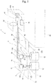
- a tidal current power generation system 1 as illustrated in Fig. 1 and the like serves as an example of the water current power generation system and has a plurality of turbines (a lift type turbine 10 and a drag type turbine 20) serving as converters which converts energy of tidal current to rotation energy of a rotator and a floater 2 floating on water.
- the lift type turbine 10 and the drag type turbine 20 are mounted to the floater 2. Rotative force generated by the lift type turbine 10 and the drag type turbine 20 is transmitted by a transmission part 6 to an electrical generator 4, which is the driven to generate electric power.
- the floater 2 is configured to float in the sea by buoyancy and used such that a part of the floater 2 is located below sea level and the rest part of the floater 2 is located above sea level.
- the floater 2 includes a body 2A formed into a rectangular shape in a planar view and an upper surface of the body 2A is disposed above sea level.
- the floater 2 maybe structured such that the body 2A itself is floatable in the water or a plurality of parts floatable in the water (floating parts) is coupled to the body 2A.
- a part of the transmission part 6 is mounted on the body 2A, and the lift type turbine 10 and the drag type turbine 20 are held by the body 2A.
- the lift type turbine 10 includes a first rotator 12 and the drag type turbine 20 includes a second rotator 22, both of rotors 12 and 22 being disposed so as to extend downward from the underside of the body 2A.
- the floater 2 is connected to a land part 60 by a bridge 62 serving as a connection.
- the land part 60 may be constructed as a breakwater, a pier or a quay.
- the floater 2 stays near the land part 60 while floating in the sea since the floater 2 is connected to the land part 60 by the bridge 62.
- the floater 2 may be connected to an anchor sunk on the sea bottom.
- the lift type turbine 10 is constructed as a lift type vertical-axis turbine such as a Darrieus turbine, for example.
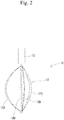
- Fig. 2 exemplifies the lift type turbine 10 constructed as the Darrieus turbine.
- the lift type turbine 10 includes the first rotator 12 which is subjected to a tidal current to generate a lift force and further generate a rotative force by the lift force, and a bearing part 13 rotatably holding a rotating shaft 12D serving as a center of rotation of the first rotator 12.
- the lift type turbine 10 is mounted to the floater 2 with the first rotator 12 being disposed in the water.
- the bearing part 13 is fixed to the body 2A of the floater 2 as illustrated in Fig. 1 , for example.
- the first rotator 12 is mounted so as to extend downward below the underside of the body 2A to which the bearing part 13 is fixed.
- the lift type turbine 10 (the Darrieus turbine) as illustrated in Fig. 2 is constructed as a three-bladed turbine having three blades 12A, 12B and 12C coupled to the rotating shaft 12D.
- tidal current water current
- a lift force is generated by the three blades 12A-12C subjected to the tidal current, and a circumferential force is generated by the lift force in each of the blades 12A-12C.
- the first rotator 12 is rotated in the water by the circumferential force.
- the principle of rotation of the Darrieus turbine is known and accordingly will not be described in detail here.
- the drag type turbine 20 is constructed as a drag type vertical-axis turbine such as the Savonius turbine, for example.
- Fig. 3 exemplifies the drag type turbine 20 constructed as the Savonius turbine.
- the drag type turbine 20 includes the second rotator 22 which is subjected to a tidal current to generate a drag force and further generate a rotative force by the drag force, and a bearing part 23 rotatably supporting a rotating shaft 22D serving as a center of rotation of the second rotator 22.
- the drag type turbine 20 is mounted to the floater 2 with the second rotator 22 being disposed in the water.
- the bearing part 23 is fixed to the body 2A of the floater 2 as illustrated in Fig. 1 , for example.
- the second rotator 22 is mounted so as to extend downward below the underside of the body 2A to which the bearing part 23 is fixed.
- the drag type turbine 20 (the Savonius turbine) as illustrated in Fig. 3 includes a rotating shaft 22D, an upper support plate 22E and a lower support plate 22F both of which are coupled to the rotating shaft 22D.
- the drag type turbine 20 has two blades 22A and 22B coupled to the upper and lower supports 22E and 22F so that the drag type turbine 20 is constructed as a two-bladed Savonius turbine.
- the rotating shaft 22D has a lower end connected to a central part of the upper support plate 22E formed into the shape of a disc.
- the blades 22A and 22B are constituted of two semi-cylindrical members and disposed to be symmetric about a central axis (the center of rotation) of the rotating shaft 22D.
- the blades 22A and 22B have respective upper ends connected to the upper support plate 22E and respective lower ends connected to the lower support plate 22F.
- tidal current water current
- a drag force is generated by the blades 22A and 22B subjected to the tidal current, and a circumferential force is generated by the drag force in each of the blades 22A and 22B.
- the second rotator 22 is rotated in the water by the circumferential force.
- the principle of rotation of the Savonius turbine is known and accordingly will not be described in detail here.
- the transmission part 6 as illustrated in Fig. 1 transmits to the generator 4 a rotative force of the first rotator 12 of the lift type turbine 10 and a rotative force of the second rotator 22 of the drag type turbine 20.
- the transmission part 6 includes a first speed increaser 14, a second speed increaser 24, a first fluid pressure pump 15, a second fluid pressure pump 25, a first flow passage 16, a second flow passage 26, a common passage 30 and a fluid pressure motor 40.
- the first speed increaser 14 serves as an example of a first speed increasing part and works in conjunction with rotation of the first rotator 12 of the lift type turbine 10 to rotate a rotating part of the first fluid pressure pump 15 at a rotational speed higher than a rotational speed of the first rotator 12.
- the first speed increaser 14 is constructed as a speed-up gear which increases a rotational speed by a plurality of toothed gears, for example.
- the rotating shaft 12D of the first rotator 12 serves as an input shaft of the first speed increaser 14.
- the rotating shaft 14D connected to the rotating part of the first fluid pressure pump 15 serves as an output shaft of the first speed increaser 14.
- the first speed increaser 14 transmits power so that a rotational speed of the rotating shaft 14D is higher than that of the rotating shaft 12D by the gear transmission mechanism working in conjunction with the rotation of the rotating shaft 12D.
- the second speed increaser 24 serves as an example of a second speed increasing part and works in conjunction with rotation of the second rotator 22 of the drag type turbine 20 to rotate a rotating part of the second fluid pressure pump 25 at a rotational speed higher than a rotational speed of the second rotator 22.
- the second speed increaser 24 is constructed as a speed-up gear which increases a rotational speed by a plurality of toothed gears, for example.
- the rotating shaft 22D of the second rotator 22 serves as an input shaft of the second speed increaser 24.
- the rotating shaft 24D connected to the rotating part of the second fluid pressure pump 25 serves as an output shaft of the second speed increaser 24.
- the second speed increaser 24 transmits power so that a rotational speed of the rotating shaft 24D is higher than that of the rotating shaft 22D by the gear transmission mechanism working in conjunction with the rotation of the rotating shaft 22D.
- Each of the first and second fluid pressure pumps 15 and 25 is constructed as a known hydraulic pump such as a screw pump, a vane pump, a gear pump or a plunger pump, for example, and uses oil as an operating fluid and is configured to convert rotation of the input shaft to fluid energy.
- the first fluid pressure pump 15 is driven in conjunction with rotation of the first rotator 12 of the lift type turbine 10 and has a function of causing the operating fluid (hydraulic fluid) to flow in the first passage 16.
- the first fluid pressure pump 15 includes a first port 15A through which the hydraulic fluid flows out of the first fluid pressure pump 15, a second port 15B through which the hydraulic fluid flows into the first fluid pressure pump 15, and a rotating part (a driving part) not illustrated which is coupled to the rotating shaft 14D of the first speed increaser 14.
- the first fluid pressure pump 15 works in conjunction with rotation of the rotating shaft 14D of the first speed increaser 14 to rotate the rotating part (the driving part), thereby causing the hydraulic fluid to flow through the second port 15B into the first fluid pressure pump 15 and to flow through the first port 15A out of the first fluid pressure pump 15.
- the second fluid pressure pump 25 is driven in conjunction with rotation of the second rotator 22 of the drag type turbine 20 and has a function of causing the operating fluid (the hydraulic fluid) to flow in the second passage 26.
- the second fluid pressure pump 25 includes a first port 25A through which the hydraulic fluid flows out of the second fluid pressure pump 25, a second port 25B through which the hydraulic fluid flows into the second fluid pressure pump 25, and a rotating part (a driving part) not illustrated which is coupled to the rotating shaft 24D of the second speed increaser 24.
- the second fluid pressure pump 25 works in conjunction with rotation of the rotating shaft 24D of the second speed increaser 24 to rotate the rotating part (the driving part), thereby causing the hydraulic fluid to flow through the second port 25B into the second fluid pressure pump 25 and to flow through the second port 25A out of the second fluid pressure pump 25.
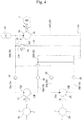
- the transmission part 6 includes a hydraulic fluid circulation passage 6A communicating with the first and second fluid pressure pumps 15 and 25.
- the circulation passage 6A includes a first flow passage 16 communicating with the first fluid pressure pump 15 and a second flow passage 26 communicating with the second hydraulic pump 25.
- the circulation passage 6A further includes a common flow passage 30 which communicates with both first and second flow passages 16 and 26 and serves as a passage common to the fluid flowing in the first flow passage 16 and the fluid flowing in the second flow passage 26.
- the common flow passage 30 includes a joint passage 30A where the hydraulic fluid flowing out of the first fluid pressure pump 15 and the hydraulic fluid flowing out of the second fluid pressure pump 25 join together and flow, an outflow passage 30C serving as a passage of the hydraulic fluid flowing out of the fluid pressure motor 40, and a common passage 30B serving as a common passage for the hydraulic fluid flowing out of a tank 54.
- the first flow passage 16 communicating with the first fluid pressure pump 15 includes an outflow side passage 16A communicating with the first port 15A and an inflow side passage 16B communicating with the second port 15B.
- the outflow side passage 16A is provided with a check valve 19 which allows the hydraulic fluid to flow from the first fluid pressure pump 15 toward the joint passage 30A and blocks the reverse flow.
- the inflow side passage 16B is provided with a check valve 18 which allows the hydraulic fluid to flow from the common passage 30B toward the first fluid pressure pump 15 and blocks the reverse flow.
- a circulation passage at the first fluid pressure pump 15 side is constituted of the outflow side passage 16A, the joint passage 30A, the tank 54, the common passage 30B and the inflow side passage 16B. The hydraulic fluid is circulated in this circulation passage by the drive of the first fluid pressure pump 15.
- the second flow passage 26 communicating with the second fluid pressure pump 25 includes an outflow side passage 26A communicating with the first port 25A and an inflow side passage 26B communicating with the second port 25B.
- the outflow side passage 26A is provided with a check valve 29 which allows the hydraulic fluid to flow from the second fluid pressure pump 25 toward the joint passage 30A and blocks the reverse flow.
- the inflow side passage 26B is provided with a check valve 28 which allows the hydraulic fluid to flow from the common passage 30B toward the second fluid pressure pump 25 and blocks the reverse flow.
- a circulation passage at the second fluid pressure pump 25 side is constituted of the outflow side passage 26A, the joint passage 30A, the tank 54, the common passage 30B and the inflow side passage 26B. The hydraulic fluid is circulated in this circulation passage by the drive of the second fluid pressure pump 25.
- the circulation passage 6A is provided with a branch passage 32 branching off from the joint passage 30A and a pressure relief valve 34 interposed in the branch passage 32.
- the pressure relief valve 34 has an inlet port 34A communicating with one of two sides of the branch passage 32 and an outlet port 34B communicating with the other side of the branch passage 32.
- the pressure relief valve 34 causes the hydraulic fluid to flow from the outlet port 34B side toward the tank 54.
- the hydraulic fluid flows from the joint passage 30A through the branch passage 32 to the tank 54 side.
- the joint passage 30A is provided with a hydraulic accumulator 52 for suppression of impact pressure and damping of pulsation.
- the fluid pressure motor 40 is constructed as a hydraulic motor with a known structure, such as a hydraulic gear motor, a vane motor or a plunger motor and is provided so as to be interposed in the common flow passage 30 constituting the circulation passage 6A.
- the fluid pressure motor 40 has an inlet port 41 connected to the joint passage 30A, so that the hydraulic fluid flowing through the joint passage 30A further flows through the inlet port 41 to the fluid pressure motor 40.
- the fluid pressure motor 40 also has an outlet port 42 connected to the outflow passage 30C. The hydraulic fluid flowing out through the outlet port 42 further flows through the outflow passage 30C into the tank 54.
- the fluid pressure motor 40 thus constructed is operated in response to flowing of the hydraulic fluid in the common passage 30 from the joint passage 30A to the outflow passage 30C, so that a rotating shaft 40A ( Fig. 1 ) is rotated.
- the generator 4 generates electric power by the drive of the fluid pressure motor 40 and is constructed as a known DC or AC generator, for example.
- the generator 4 includes a rotating shaft (not illustrated) directly connected to the rotating shaft 40A of the fluid pressure motor 40. Consequently, when the hydraulic fluid flows in the common passage 30 so that the rotating shaft 40A is rotated, the rotating shaft of the generator 4 is also rotated in conjunction with the rotating shaft 40A, with the result that the generator 4 generates electric power by the rotation of the rotating shaft thereof.
- Fig. 5 schematically illustrates an electrical arrangement of the tidal current generation system 1.
- a voltage conversion part 80 Upon start of generation by the generator 4, electric power delivered from the generator 4 is supplied to a voltage conversion part 80 thereby to be converted to a desired output voltage.
- the voltage conversion part 80 may be constructed as a converter which converts an AC voltage generated by the generator 4 to a desired DC voltage.
- a battery 70 is charged with the output voltage (DC voltage) from the voltage conversion part 80.
- an electric lamp 72 serving as a light source is electrically connected to the battery 70, so that the electric lamp 72 is operated by the electric power from the battery 70 thereby to emit light.
- Another load 74 is also connected to the battery 70.
- the tidal current power generation system 1 may be constructed as equipment which can perform system connection.
- the generator 4 when the generator 4 is constructed as an AC generator, the voltage conversion part 80 may be constructed as an AC/DC converter, and being connected to this, a DC/AC converter, a transformer, a system connection protection device may be sequentially provided so that the system connection may be performed in a DC link configuration.
- a load constituted as AC equipment may be connected to a rear stage of the transformer.
- a rotational force can be generated in the first rotator 12 of the lift type turbine 10 and the second rotator 22 of the drag type turbine 20.
- the rotating shafts 14D and 24D of the first and second speed increasers 14 and 24 respectively connected to the first and second rotators 12 and 22 are rotated.
- the first and second fluid pressure pumps 15 and 25 are driven in conjunction with the rotation of the rotating shafts 14D and 24D.
- the hydraulic fluid is then caused to flow out through the first ports 15A and 25A of the first and second fluid pressure pumps 15 and 25 as illustrated in Fig. 4 .
- the hydraulic fluid from the first port 15A and the hydraulic fluid from the first port 25A join together in the joint passage 30A and flow toward the fluid pressure motor 40.
- the hydraulic fluid having flowed through the joint passage 30A flows through the inlet port 41 into the fluid pressure motor 40.
- the hydraulic fluid having flowed into the fluid pressure motor 40 flows in a predetermined direction in the fluid pressure motor 40.
- the fluid pressure motor 40 is subjected to a force from the hydraulic fluid thus flowing, with the result that the fluid pressure motor 40 is driven so that the rotating shaft 40A ( Fig. 1 ) is rotated in one direction.
- the hydraulic fluid having passed through the fluid pressure motor 40 flows through the outlet port 42 out of the fluid pressure motor 40 and flows through the outflow passage 30C into the tank 54.
- the hydraulic fluid flows from the tank 54 through the common passage 30B.
- the hydraulic fluid is then caused to diverge by the inflow side passages 16B and 26B thereby to be supplied to the first and second fluid pressure pumps 15 and 25.
- the first and second fluid pressure pumps 15 and 25 are driven when the lift type turbine 10 and the drag type turbine 20 are rotated by use of water flow energy.
- the hydraulic fluid is circulated in the circulation passage 6A which is constituted of the outflow passages 16A and 26A, the joint passage 30A, the outflow passage 30C, the tank 54, the common passage 30B and the inflow side passages 16B and 26B.
- the fluid pressure motor 40 is continuously driven and accordingly the rotating shaft 40A of the fluid pressure motor 40 is continuously rotated. Since the rotating shaft of the generator 4 is rotated with rotation of the rotating shaft 40A of the fluid pressure motor 40, the generator 4 generates electric power.
- the second fluid pressure pump 25 performs a discharging operation so that the hydraulic fluid is circulated in the circulation passage 6A, with the result that the fluid pressure motor 40 and the generator 4 are driven.
- the first fluid pressure pump 15 performs a discharging operation so that the hydraulic fluid is circulated in the circulation passage 6A, with the result that the fluid pressure motor 40 and the generator 4 are driven.
- the tidal current power generation system 1 includes the lift type turbine 10 and the drag type turbine 20 and is configured so that rotative forces of the first and second rotators 12 and 22 respectively provided on the turbines 10 and 20 are transmitted to the generator 4 by the transmission part 6.
- the first rotator 12 can be efficiently rotated so that the generator 4 can be operated using at least the rotative force of the first rotator 12.
- the second rotator 22 can be efficiently rotated so that the generator 4 can be operated using the rotative force of the second rotator 22.
- the rotator can be more efficiently rotated in the above-described configuration, with the result that it is possible to ease the conditions under which electric power can be successfully generated and to expand the range in which energy can be converted.
- the transmission part 6 of the tidal current power generation system 1 includes the first fluid pressure pump 15 driven in conjunction with rotation of the first rotator 12 of the lift type turbine 10 and the second fluid pressure pump 25 driven in conjunction with rotation of the second rotator 22 of the drag type turbine 20.
- the first fluid pressure pump 15 is configured to cause the fluid to flow in the first passage 16
- the second fluid pressure pump 25 is configured to cause the fluid to flow in the second passage 26.
- the common flow passage 30 is provided which communicates with first and second flow passages 16 and 26.
- the common flow passage 30 serves as a passage common to the fluid flowing in the first flow passage 16 and the fluid flowing in the second flow passage 26.
- the fluid pressure motor 40 is operated in response to flowing of the fluid in the common flow passage 30 to drive the generator 4.
- both of the rotative force of the first rotator 12 of the lift type turbine 10 and the rotative force of the second rotator 22 of the drag type turbine 20 can be converted to the rotative force of the fluid pressure motor 40, with the result that the fluid pressure motor 40 can rotate the generator 4 with higher torque. Furthermore, even when fluctuation in rotation occurs such that the rotational speed in each of the turbines is reduced to such an extent that power generation is difficult by each turbine alone, power generation can be continued as long as the fluid pressure motor 40 reflecting the operations of both turbines is in a rotating state capable of generating electric power.
- the flow rate of hydraulic fluid flowing into the fluid pressure motor 40 can be averaged even when rotations of the turbines (the lift type turbine 10 and the drag type turbine 20) are not constant and the flow rates of the hydraulic fluid discharged from the respective first and second fluid pressure pumps 15 and 25 fluctuate.
- the fluid pressure motor 40 can be stably rotated and the generator 4 can stably generate electric power.
- the tidal current power generation system 1 is configured so that the single fluid pressure motor 40 and the single generator 4 are driven by a plurality of turbines (the lift type turbine 10 and the drag type turbine 20) .
- a plurality of turbines the lift type turbine 10 and the drag type turbine 20
- capacities of the hydraulic motor and the generator can be rendered larger as compared with the case where a plurality of hydraulic motors and a plurality of generators are provided so as to correspond to the respective turbines.
- the costs of the equipment can be reduced.
- the tidal current power generation system 1 includes the first and second speed increasers 14 and 24.
- the first speed increaser 14 works in conjunction with rotation of the first rotator 12 of the lift type turbine 10 to rotate the rotation part of the first fluid pressure pump 15 at the rotational speed higher than that of the first rotator 12.
- the second speed increaser 24 works in conjunction with rotation of the second rotator 22 to rotate the rotation part of the second fluid pressure pump 25 at the rotational speed higher than that of the second rotator 22.
- the rotational speeds of the rotation parts of the first and second fluid pressure pumps 15 and 25 can be rendered higher than the rotational speeds of the corresponding rotators, with the result that it is possible to improve the efficiencies of the first and second fluid pressure pumps 15 and 25.
- the tidal current power generation system 1 includes the floater 2 floating on water.
- the lift type turbine 10 is mounted to the floater 2 in such a manner that the first rotator 12 is disposed in the water
- the drag type turbine 20 is mounted to the floater 2 in such a manner that the second rotator 22 is disposed in the water.
- both lift type and drag type turbines can be provided without being directly fixed to the ground with the result that the space necessary on the ground can be reduced.
- the lift type and drag type turbines 10 and 20 need not be completely fixed to the sea bottom or the land surface and the turbines can be moved together with the floater.
- the floater 2 is moved up or down according to the increase or decrease in the water level. Consequently, the relative positional relationship between the water level and the lift type and the drag type turbines can be maintained without significant change.
- the tidal current power generation system 1 includes the lamp 72 configured to emit light using the electric power generated by the generator 4. According to this configuration, an independent power source can be secured by sued of the lift type and drag type turbines 10 and 20, and a system which generates light by the electric power resulting from the power source can be built.
Landscapes
- Engineering & Computer Science (AREA)
- Chemical & Material Sciences (AREA)
- Combustion & Propulsion (AREA)
- Mechanical Engineering (AREA)
- General Engineering & Computer Science (AREA)
- Life Sciences & Earth Sciences (AREA)
- General Life Sciences & Earth Sciences (AREA)
- Oceanography (AREA)
- Power Engineering (AREA)
- Other Liquid Machine Or Engine Such As Wave Power Use (AREA)
- Hydraulic Turbines (AREA)
Abstract
Description
- The present invention relates to a water current power generation system.
-
Patent Document 1 discloses an example of power generation system with use of tidal current. A tidal current power generation facility disclosed byPatent Document 1 includes a floating tidal current power generation system having a turbine for power generation, an electrical generator, and a diffusion device. A mooring guide yoke is rotatably provided on a mooring anchor fixed to the sea bottom, and the tidal current power generation system is coupled to the mooring guide yoke by mooring chains. - Patent Document 1: Japanese Patent Application Publication No.
JP-A-2005-351201 - This type of power generation system conventionally suggested uses only a specific type of turbine, so that tidal current energy can be efficiently converted to rotative force under condition of tidal current suitable for characteristics of the turbine. However, tidal current energy cannot be efficiently converted to rotative force when tidal current is unsuitable for the characteristics of the turbine.
- It is generally known that the efficiency (power factor) of a turbine is expressed as a function of a peripheral speed ratio (a ratio of peripheral speed of a blade to the flow velocity) and that the relationship between the efficiency and the peripheral speed ratio varies depending upon the shape of the blade. For example, when compared with a Darrieus type turbine, a Savonius type turbine produces a significant efficiency in a relatively lower peripheral speed ratio range. The Darrieus type turbine produces a significant efficiency in a higher peripheral speed ratio range than the Savonius type turbine.
- As described above, since an efficient peripheral speed ratio range depends upon the shape of turbine, the turbine cannot be efficiently rotated under the conditions out of the efficient peripheral speed ratio range with the result that the power generation efficiency becomes low. For example, in use of the Savonius type turbine for power generation, the turbine cannot be efficiently rotated when the peripheral speed ratio is within the range unsuitable for the Savonius type turbine (the relatively higher range), with the result that the power generation efficiency becomes extremely low. Likewise, in use of the Darrieus type turbine for power generation, the turbine cannot be efficiently rotated when the peripheral speed ratio is within the range unsuitable for the Darrieus type turbine (the relatively lower range), with the result that the power generation efficiency becomes extremely low. Thus, the efficient peripheral speed ratio range is limited according to the shape of turbine, so that power cannot be successfully generated under the conditions out of the efficient peripheral speed ratio range.
- The present invention was made in view of the above-described circumstances in the conventional art and has an object to provide a water current power generation system which can ease conditions under which power can be successfully generated and can expand a range in which energy can be converted.
- A water current power generation system in accordance with the invention includes a lift type turbine provided with a first rotator which generates a lift force when subjected to a water flow and further generates a rotative force by the lift force and a drag type turbine provided with a second rotator which generates a drag force when subj ected to a water flow and further generates a rotative force by the drag force. The water current power generation system further includes a transmission part which transmits the rotative force of the first rotator of the lift type turbine and the rotative force of the second rotator of the drag type turbine to one or a plurality of generators.
- The water current power generation system of the invention includes the lift type turbine and the drag type turbine and is configured to transmit the rotative forces of the first and second rotators to the generator by the transmission part. As the result of the configuration, when a relationship between the lift type turbine and the water current is suitable for the lift type turbine, the first rotator can be efficiently rotated so that the generator can be operated using at least the rotative force of the first rotator. When the relationship between the lift type turbine and the tidal current is unsuitable for the lift type turbine but the relationship between the drag type turbine and the tidal current is suitable for the drag type turbine, the second rotator can be efficiently rotated so that the generators can be operated using the rotative force of the second rotator.
- According to the invention, as described above, it is possible to ease the conditions under which power can be successfully generated and to expand the range in which energy can be converted, as compared with the configuration using only a single type turbine.
- In the water current power generation system in accordance with the invention, the transmission part may include a first fluid pressure pump driven in conjunction with rotation of the first rotator of the lift type turbine to cause a fluid to flow in a first flow passage and a second fluid pressure pump driven in conjunction with rotation of the second rotator of the drag type turbine to cause a fluid to flow in a second flow passage. The water current power generation system may further include a common flow passage communicating with the first and second flow passages and serving as a passage common to the fluid flowing in the first flow passage and the fluid flowing in the second flow passage and a fluid pressure motor operated in response to flowing of the fluid in the common flow passage to drive the generator.
- According to the configuration, both of the rotative force of the first rotator of the lift type turbine and the rotative force of the second rotator of the drag type turbine can be converted to a rotative force of the fluid pressure motor, with the result that the fluid pressure motor can rotate the generator with higher torque. Furthermore, even when fluctuation in rotation occurs such that the rotational speed in each of the turbines is reduced to such an extent that power generation is difficult by each turbine alone, power generation can be continued as long as the fluid pressure motor reflecting the operations of both turbines is in a rotating state capable of generating electric power.
- The water current power generation system in accordance with the invention may further include a first speed increasing part operated in conjunction with rotation of the first rotator of the lift type turbine to rotate a rotating part of the first fluid pressure pump at a rotational speed higher than a rotational speed of the first rotator. In the similar manner, the water current power generation system in accordance with the invention may further include a second speed increasing part operated in conjunction with rotation of the second rotator of the drag type turbine to rotate a rotating part of the second fluid pressure pump at a rotational speed higher than a rotational speed of the second rotator.
- According to the configuration, the rotational speeds of the rotating parts of the first and second fluid pressure pumps can be rendered higher than higher than those of the corresponding rotators with the result that it is possible to improve the efficiencies of the first and second fluid pressure pumps.
- The water current power generation system in accordance with the invention may further include a floater floatable on water. The lift type turbine may be mounted to the floater in such a manner that the first rotator is disposed in water, and the drag type turbine may be mounted to the floater in such a manner that the second rotator is disposed in water.
- According to the configuration, both lift type and drag type turbines can be provided without being directly fixed to the ground with the result that the space necessary on the ground can be reduced. Moreover, the lift type and drag type turbines need not be completely fixed to the sea bottom or the land surface and the turbines can be moved together with the floater. Furthermore, even when the water level is increased or decreased, the floater is moved up or down according to the increase or decrease in the water level. Consequently, the relative positional relationship between the water level and the lift type and drag type turbines can be maintained without significant change.
- The water current power generation system in accordance with the invention may further include a light source configured to emit light using electric power generated by the generator.
- According to the configuration, an independent power source can be secured by use of the lift type and drag type turbines, and a system which generates light by the electric power resulting from the power source can be built.
- "Water current" that gives power to the water current power generation system includes not only a flow of tidal current (tidal current) caused by sea tide but also a flow of water such as ocean current. In the following description, "tidal current" refers to a flow of water on the whole occurring in the sea. Furthermore, a place of application of the water current power generation system in accordance with the invention is not limited to the sea, but also includes places in rivers, lakes and the like where water currents can occur.
-
-
Fig. 1 is a schematic view of the water current power generation system of an embodiment; -
Fig. 2 is a front view of a lift type turbine used in the water current power generation system of the embodiment; -
Fig. 3 is a perspective view of a drag type turbine used in the water current power generation system of the embodiment; -
Fig. 4 is a circuit diagram of a hydraulic circuit of the water current power generation system of the embodiment; and -
Fig. 5 is a schematic block diagram exemplifying an electrical arrangement of the water current power generation system of the embodiment. - One embodiment of the water current power generation system in accordance with the invention will be described with reference to the drawings.
- A tidal current
power generation system 1 as illustrated inFig. 1 and the like serves as an example of the water current power generation system and has a plurality of turbines (alift type turbine 10 and a drag type turbine 20) serving as converters which converts energy of tidal current to rotation energy of a rotator and afloater 2 floating on water. Thelift type turbine 10 and thedrag type turbine 20 are mounted to thefloater 2. Rotative force generated by thelift type turbine 10 and thedrag type turbine 20 is transmitted by atransmission part 6 to anelectrical generator 4, which is the driven to generate electric power. - The
floater 2 is configured to float in the sea by buoyancy and used such that a part of thefloater 2 is located below sea level and the rest part of thefloater 2 is located above sea level. In the example as illustrated inFig. 1 , thefloater 2 includes abody 2A formed into a rectangular shape in a planar view and an upper surface of thebody 2A is disposed above sea level. Thefloater 2 maybe structured such that thebody 2A itself is floatable in the water or a plurality of parts floatable in the water (floating parts) is coupled to thebody 2A. A part of thetransmission part 6 is mounted on thebody 2A, and thelift type turbine 10 and thedrag type turbine 20 are held by thebody 2A. An underside of thebody 2A is disposed in the water so as to be located below sea level, for example. Thelift type turbine 10 includes afirst rotator 12 and thedrag type turbine 20 includes asecond rotator 22, both ofrotors body 2A. - The
floater 2 is connected to aland part 60 by abridge 62 serving as a connection. Theland part 60 may be constructed as a breakwater, a pier or a quay. Thefloater 2 stays near theland part 60 while floating in the sea since thefloater 2 is connected to theland part 60 by thebridge 62. Thefloater 2 may be connected to an anchor sunk on the sea bottom. - The
lift type turbine 10 is constructed as a lift type vertical-axis turbine such as a Darrieus turbine, for example.Fig. 2 exemplifies thelift type turbine 10 constructed as the Darrieus turbine. Thelift type turbine 10 includes thefirst rotator 12 which is subjected to a tidal current to generate a lift force and further generate a rotative force by the lift force, and a bearingpart 13 rotatably holding arotating shaft 12D serving as a center of rotation of thefirst rotator 12. Thelift type turbine 10 is mounted to thefloater 2 with thefirst rotator 12 being disposed in the water. The bearingpart 13 is fixed to thebody 2A of thefloater 2 as illustrated inFig. 1 , for example. Thefirst rotator 12 is mounted so as to extend downward below the underside of thebody 2A to which the bearingpart 13 is fixed. - The lift type turbine 10 (the Darrieus turbine) as illustrated in
Fig. 2 is constructed as a three-bladed turbine having threeblades rotating shaft 12D. During occurrence of tidal current (water current) in a direction intersecting an extension direction of therotating shaft 12D, a lift force is generated by the threeblades 12A-12C subjected to the tidal current, and a circumferential force is generated by the lift force in each of theblades 12A-12C. Thefirst rotator 12 is rotated in the water by the circumferential force. The principle of rotation of the Darrieus turbine is known and accordingly will not be described in detail here. - The
drag type turbine 20 is constructed as a drag type vertical-axis turbine such as the Savonius turbine, for example.Fig. 3 exemplifies thedrag type turbine 20 constructed as the Savonius turbine. Thedrag type turbine 20 includes thesecond rotator 22 which is subjected to a tidal current to generate a drag force and further generate a rotative force by the drag force, and a bearingpart 23 rotatably supporting arotating shaft 22D serving as a center of rotation of thesecond rotator 22. Thedrag type turbine 20 is mounted to thefloater 2 with thesecond rotator 22 being disposed in the water. The bearingpart 23 is fixed to thebody 2A of thefloater 2 as illustrated inFig. 1 , for example. Thesecond rotator 22 is mounted so as to extend downward below the underside of thebody 2A to which the bearingpart 23 is fixed. - The drag type turbine 20 (the Savonius turbine) as illustrated in
Fig. 3 includes arotating shaft 22D, anupper support plate 22E and alower support plate 22F both of which are coupled to therotating shaft 22D. Thedrag type turbine 20 has twoblades lower supports drag type turbine 20 is constructed as a two-bladed Savonius turbine. Therotating shaft 22D has a lower end connected to a central part of theupper support plate 22E formed into the shape of a disc. Theblades rotating shaft 22D. Theblades upper support plate 22E and respective lower ends connected to thelower support plate 22F. During occurrence of tidal current (water current) in a direction intersecting an extension direction of therotating shaft 22D, a drag force is generated by theblades blades second rotator 22 is rotated in the water by the circumferential force. The principle of rotation of the Savonius turbine is known and accordingly will not be described in detail here. - The
transmission part 6 as illustrated inFig. 1 transmits to the generator 4 a rotative force of thefirst rotator 12 of thelift type turbine 10 and a rotative force of thesecond rotator 22 of thedrag type turbine 20. Thetransmission part 6 includes afirst speed increaser 14, asecond speed increaser 24, a firstfluid pressure pump 15, a secondfluid pressure pump 25, afirst flow passage 16, asecond flow passage 26, acommon passage 30 and afluid pressure motor 40. - The
first speed increaser 14 serves as an example of a first speed increasing part and works in conjunction with rotation of thefirst rotator 12 of thelift type turbine 10 to rotate a rotating part of the firstfluid pressure pump 15 at a rotational speed higher than a rotational speed of thefirst rotator 12. Thefirst speed increaser 14 is constructed as a speed-up gear which increases a rotational speed by a plurality of toothed gears, for example. Therotating shaft 12D of thefirst rotator 12 serves as an input shaft of thefirst speed increaser 14. Therotating shaft 14D connected to the rotating part of the firstfluid pressure pump 15 serves as an output shaft of thefirst speed increaser 14. Thefirst speed increaser 14 transmits power so that a rotational speed of therotating shaft 14D is higher than that of therotating shaft 12D by the gear transmission mechanism working in conjunction with the rotation of therotating shaft 12D. - The
second speed increaser 24 serves as an example of a second speed increasing part and works in conjunction with rotation of thesecond rotator 22 of thedrag type turbine 20 to rotate a rotating part of the secondfluid pressure pump 25 at a rotational speed higher than a rotational speed of thesecond rotator 22. Thesecond speed increaser 24 is constructed as a speed-up gear which increases a rotational speed by a plurality of toothed gears, for example. Therotating shaft 22D of thesecond rotator 22 serves as an input shaft of thesecond speed increaser 24. Therotating shaft 24D connected to the rotating part of the secondfluid pressure pump 25 serves as an output shaft of thesecond speed increaser 24. Thesecond speed increaser 24 transmits power so that a rotational speed of therotating shaft 24D is higher than that of therotating shaft 22D by the gear transmission mechanism working in conjunction with the rotation of therotating shaft 22D. - Each of the first and second fluid pressure pumps 15 and 25 is constructed as a known hydraulic pump such as a screw pump, a vane pump, a gear pump or a plunger pump, for example, and uses oil as an operating fluid and is configured to convert rotation of the input shaft to fluid energy.
- The first
fluid pressure pump 15 is driven in conjunction with rotation of thefirst rotator 12 of thelift type turbine 10 and has a function of causing the operating fluid (hydraulic fluid) to flow in thefirst passage 16. The firstfluid pressure pump 15 includes afirst port 15A through which the hydraulic fluid flows out of the firstfluid pressure pump 15, asecond port 15B through which the hydraulic fluid flows into the firstfluid pressure pump 15, and a rotating part (a driving part) not illustrated which is coupled to therotating shaft 14D of thefirst speed increaser 14. The firstfluid pressure pump 15 works in conjunction with rotation of therotating shaft 14D of thefirst speed increaser 14 to rotate the rotating part (the driving part), thereby causing the hydraulic fluid to flow through thesecond port 15B into the firstfluid pressure pump 15 and to flow through thefirst port 15A out of the firstfluid pressure pump 15. - The second
fluid pressure pump 25 is driven in conjunction with rotation of thesecond rotator 22 of thedrag type turbine 20 and has a function of causing the operating fluid (the hydraulic fluid) to flow in thesecond passage 26. The secondfluid pressure pump 25 includes afirst port 25A through which the hydraulic fluid flows out of the secondfluid pressure pump 25, asecond port 25B through which the hydraulic fluid flows into the secondfluid pressure pump 25, and a rotating part (a driving part) not illustrated which is coupled to therotating shaft 24D of thesecond speed increaser 24. The secondfluid pressure pump 25 works in conjunction with rotation of therotating shaft 24D of thesecond speed increaser 24 to rotate the rotating part (the driving part), thereby causing the hydraulic fluid to flow through thesecond port 25B into the secondfluid pressure pump 25 and to flow through thesecond port 25A out of the secondfluid pressure pump 25. - The
transmission part 6 includes a hydraulic fluid circulation passage 6A communicating with the first and second fluid pressure pumps 15 and 25. The circulation passage 6A includes afirst flow passage 16 communicating with the firstfluid pressure pump 15 and asecond flow passage 26 communicating with the secondhydraulic pump 25. The circulation passage 6A further includes acommon flow passage 30 which communicates with both first andsecond flow passages first flow passage 16 and the fluid flowing in thesecond flow passage 26. Thecommon flow passage 30 includes ajoint passage 30A where the hydraulic fluid flowing out of the firstfluid pressure pump 15 and the hydraulic fluid flowing out of the secondfluid pressure pump 25 join together and flow, anoutflow passage 30C serving as a passage of the hydraulic fluid flowing out of thefluid pressure motor 40, and acommon passage 30B serving as a common passage for the hydraulic fluid flowing out of atank 54. - The
first flow passage 16 communicating with the firstfluid pressure pump 15 includes anoutflow side passage 16A communicating with thefirst port 15A and aninflow side passage 16B communicating with thesecond port 15B. Theoutflow side passage 16A is provided with acheck valve 19 which allows the hydraulic fluid to flow from the firstfluid pressure pump 15 toward thejoint passage 30A and blocks the reverse flow. Theinflow side passage 16B is provided with acheck valve 18 which allows the hydraulic fluid to flow from thecommon passage 30B toward the firstfluid pressure pump 15 and blocks the reverse flow. In the circulation passage 6A, a circulation passage at the firstfluid pressure pump 15 side is constituted of theoutflow side passage 16A, thejoint passage 30A, thetank 54, thecommon passage 30B and theinflow side passage 16B. The hydraulic fluid is circulated in this circulation passage by the drive of the firstfluid pressure pump 15. - The
second flow passage 26 communicating with the secondfluid pressure pump 25 includes anoutflow side passage 26A communicating with thefirst port 25A and aninflow side passage 26B communicating with thesecond port 25B. Theoutflow side passage 26A is provided with acheck valve 29 which allows the hydraulic fluid to flow from the secondfluid pressure pump 25 toward thejoint passage 30A and blocks the reverse flow. Theinflow side passage 26B is provided with acheck valve 28 which allows the hydraulic fluid to flow from thecommon passage 30B toward the secondfluid pressure pump 25 and blocks the reverse flow. In the circulation passage 6A, a circulation passage at the secondfluid pressure pump 25 side is constituted of theoutflow side passage 26A, thejoint passage 30A, thetank 54, thecommon passage 30B and theinflow side passage 26B. The hydraulic fluid is circulated in this circulation passage by the drive of the secondfluid pressure pump 25. - When both first and second fluid pressure pumps 15 and 25 are being driven, the hydraulic fluid from the
tank 54 is caused to flow into thesecond port 15B of the firstfluid pressure pump 15 and thesecond port 25B of the secondfluid pressure pump 25. Then, the hydraulic fluid flowing out of thefirst port 15A of the firstfluid pressure pump 15 and the hydraulic fluid flowing out of thefirst port 25A of the secondfluid pressure pump 25 join together in thejoint passage 30A and flow in thejoint passage 30A. - The circulation passage 6A is provided with a
branch passage 32 branching off from thejoint passage 30A and apressure relief valve 34 interposed in thebranch passage 32. Thepressure relief valve 34 has aninlet port 34A communicating with one of two sides of thebranch passage 32 and anoutlet port 34B communicating with the other side of thebranch passage 32. When pressure of the hydraulic fluid at theinlet port 34A side exceeds a predetermined pressure, thepressure relief valve 34 causes the hydraulic fluid to flow from theoutlet port 34B side toward thetank 54. In this case, the hydraulic fluid flows from thejoint passage 30A through thebranch passage 32 to thetank 54 side. Furthermore, thejoint passage 30A is provided with ahydraulic accumulator 52 for suppression of impact pressure and damping of pulsation. - The
fluid pressure motor 40 is constructed as a hydraulic motor with a known structure, such as a hydraulic gear motor, a vane motor or a plunger motor and is provided so as to be interposed in thecommon flow passage 30 constituting the circulation passage 6A. Thefluid pressure motor 40 has aninlet port 41 connected to thejoint passage 30A, so that the hydraulic fluid flowing through thejoint passage 30A further flows through theinlet port 41 to thefluid pressure motor 40. Thefluid pressure motor 40 also has anoutlet port 42 connected to theoutflow passage 30C. The hydraulic fluid flowing out through theoutlet port 42 further flows through theoutflow passage 30C into thetank 54. Thefluid pressure motor 40 thus constructed is operated in response to flowing of the hydraulic fluid in thecommon passage 30 from thejoint passage 30A to theoutflow passage 30C, so that arotating shaft 40A (Fig. 1 ) is rotated. - The
generator 4 generates electric power by the drive of thefluid pressure motor 40 and is constructed as a known DC or AC generator, for example. Thegenerator 4 includes a rotating shaft (not illustrated) directly connected to therotating shaft 40A of thefluid pressure motor 40. Consequently, when the hydraulic fluid flows in thecommon passage 30 so that therotating shaft 40A is rotated, the rotating shaft of thegenerator 4 is also rotated in conjunction with therotating shaft 40A, with the result that thegenerator 4 generates electric power by the rotation of the rotating shaft thereof. -
Fig. 5 schematically illustrates an electrical arrangement of the tidalcurrent generation system 1. Upon start of generation by thegenerator 4, electric power delivered from thegenerator 4 is supplied to avoltage conversion part 80 thereby to be converted to a desired output voltage. For example, when thegenerator 4 is an AC generator, thevoltage conversion part 80 may be constructed as a converter which converts an AC voltage generated by thegenerator 4 to a desired DC voltage. In this case, abattery 70 is charged with the output voltage (DC voltage) from thevoltage conversion part 80. - In the arrangement of
Fig. 5 , anelectric lamp 72 serving as a light source is electrically connected to thebattery 70, so that theelectric lamp 72 is operated by the electric power from thebattery 70 thereby to emit light. Anotherload 74 is also connected to thebattery 70. - Although an example of electrical arrangement of the tidal current
power generation system 1 is schematically illustrated inFig. 5 , another arrangement may be employed. The tidal currentpower generation system 1 may be constructed as equipment which can perform system connection. For example, when thegenerator 4 is constructed as an AC generator, thevoltage conversion part 80 may be constructed as an AC/DC converter, and being connected to this, a DC/AC converter, a transformer, a system connection protection device may be sequentially provided so that the system connection may be performed in a DC link configuration. In this case, a load constituted as AC equipment may be connected to a rear stage of the transformer. - Next, a power generating operation of the tidal current
power generation system 1 will be described. - In the tidal current
power generation system 1 as illustrated inFig. 1 , when flow of water occurs near thelift type turbine 10 and thedrag type turbine 20 both disposed in the sea, a rotational force can be generated in thefirst rotator 12 of thelift type turbine 10 and thesecond rotator 22 of thedrag type turbine 20. For example, when both of the first andsecond rotators shafts second speed increasers second rotators rotating shafts first ports Fig. 4 . The hydraulic fluid from thefirst port 15A and the hydraulic fluid from thefirst port 25A join together in thejoint passage 30A and flow toward thefluid pressure motor 40. The hydraulic fluid having flowed through thejoint passage 30A flows through theinlet port 41 into thefluid pressure motor 40. The hydraulic fluid having flowed into thefluid pressure motor 40 flows in a predetermined direction in thefluid pressure motor 40. Thefluid pressure motor 40 is subjected to a force from the hydraulic fluid thus flowing, with the result that thefluid pressure motor 40 is driven so that therotating shaft 40A (Fig. 1 ) is rotated in one direction. The hydraulic fluid having passed through thefluid pressure motor 40 flows through theoutlet port 42 out of thefluid pressure motor 40 and flows through theoutflow passage 30C into thetank 54. When flowing out of the first and second fluid pressure pumps 15 and 25 through the respectivefirst ports tank 54 through thecommon passage 30B. The hydraulic fluid is then caused to diverge by theinflow side passages - As described above, the first and second fluid pressure pumps 15 and 25 are driven when the
lift type turbine 10 and thedrag type turbine 20 are rotated by use of water flow energy. By the drive of the first and second fluid pressure pumps 15 and 25, the hydraulic fluid is circulated in the circulation passage 6A which is constituted of theoutflow passages joint passage 30A, theoutflow passage 30C, thetank 54, thecommon passage 30B and theinflow side passages fluid pressure motor 40 is continuously driven and accordingly therotating shaft 40A of thefluid pressure motor 40 is continuously rotated. Since the rotating shaft of thegenerator 4 is rotated with rotation of therotating shaft 40A of thefluid pressure motor 40, thegenerator 4 generates electric power. - Furthermore, when the
first rotator 12 of thelift type turbine 10 is not rotated due to the condition of water current but thesecond rotator 22 of thedrag type turbine 20 is being rotated, the secondfluid pressure pump 25 performs a discharging operation so that the hydraulic fluid is circulated in the circulation passage 6A, with the result that thefluid pressure motor 40 and thegenerator 4 are driven. In the same manner, when thesecond rotator 22 of thedrag type turbine 20 is not rotated due to the condition of water current but thefirst rotator 12 of thelift type turbine 10 is being rotated, the firstfluid pressure pump 15 performs a discharging operation so that the hydraulic fluid is circulated in the circulation passage 6A, with the result that thefluid pressure motor 40 and thegenerator 4 are driven. - As described above, the tidal current
power generation system 1 includes thelift type turbine 10 and thedrag type turbine 20 and is configured so that rotative forces of the first andsecond rotators turbines generator 4 by thetransmission part 6. As the result of this configuration, when the relationship between thelift type turbine 10 and the tidal current is suitable for thelift type turbine 10, thefirst rotator 12 can be efficiently rotated so that thegenerator 4 can be operated using at least the rotative force of thefirst rotator 12. When the relationship between thelift type turbine 10 and the tidal current is unsuitable for thelift type turbine 10 but the relationship between thedrag type turbine 20 and the tidal current is suitable for thedrag type turbine 20, thesecond rotator 22 can be efficiently rotated so that thegenerator 4 can be operated using the rotative force of thesecond rotator 22. - Thus, as compared with a configuration using only a single type turbine, the rotator can be more efficiently rotated in the above-described configuration, with the result that it is possible to ease the conditions under which electric power can be successfully generated and to expand the range in which energy can be converted.
- The
transmission part 6 of the tidal currentpower generation system 1 includes the firstfluid pressure pump 15 driven in conjunction with rotation of thefirst rotator 12 of thelift type turbine 10 and the secondfluid pressure pump 25 driven in conjunction with rotation of thesecond rotator 22 of thedrag type turbine 20. The firstfluid pressure pump 15 is configured to cause the fluid to flow in thefirst passage 16, and the secondfluid pressure pump 25 is configured to cause the fluid to flow in thesecond passage 26. Thecommon flow passage 30 is provided which communicates with first andsecond flow passages common flow passage 30 serves as a passage common to the fluid flowing in thefirst flow passage 16 and the fluid flowing in thesecond flow passage 26. Thefluid pressure motor 40 is operated in response to flowing of the fluid in thecommon flow passage 30 to drive thegenerator 4. - According to this configuration, both of the rotative force of the
first rotator 12 of thelift type turbine 10 and the rotative force of thesecond rotator 22 of thedrag type turbine 20 can be converted to the rotative force of thefluid pressure motor 40, with the result that thefluid pressure motor 40 can rotate thegenerator 4 with higher torque. Furthermore, even when fluctuation in rotation occurs such that the rotational speed in each of the turbines is reduced to such an extent that power generation is difficult by each turbine alone, power generation can be continued as long as thefluid pressure motor 40 reflecting the operations of both turbines is in a rotating state capable of generating electric power. - In the tidal current
power generation system 1, the flow rate of hydraulic fluid flowing into thefluid pressure motor 40 can be averaged even when rotations of the turbines (thelift type turbine 10 and the drag type turbine 20) are not constant and the flow rates of the hydraulic fluid discharged from the respective first and second fluid pressure pumps 15 and 25 fluctuate. As a result, thefluid pressure motor 40 can be stably rotated and thegenerator 4 can stably generate electric power. - The tidal current
power generation system 1 is configured so that the singlefluid pressure motor 40 and thesingle generator 4 are driven by a plurality of turbines (thelift type turbine 10 and the drag type turbine 20) . As a result, capacities of the hydraulic motor and the generator can be rendered larger as compared with the case where a plurality of hydraulic motors and a plurality of generators are provided so as to correspond to the respective turbines. Furthermore, the costs of the equipment can be reduced. - The tidal current
power generation system 1 includes the first andsecond speed increasers first speed increaser 14 works in conjunction with rotation of thefirst rotator 12 of thelift type turbine 10 to rotate the rotation part of the firstfluid pressure pump 15 at the rotational speed higher than that of thefirst rotator 12. Thesecond speed increaser 24 works in conjunction with rotation of thesecond rotator 22 to rotate the rotation part of the secondfluid pressure pump 25 at the rotational speed higher than that of thesecond rotator 22. According to this configuration, the rotational speeds of the rotation parts of the first and second fluid pressure pumps 15 and 25 can be rendered higher than the rotational speeds of the corresponding rotators, with the result that it is possible to improve the efficiencies of the first and second fluid pressure pumps 15 and 25. - The tidal current
power generation system 1 includes thefloater 2 floating on water. Thelift type turbine 10 is mounted to thefloater 2 in such a manner that thefirst rotator 12 is disposed in the water, and thedrag type turbine 20 is mounted to thefloater 2 in such a manner that thesecond rotator 22 is disposed in the water. According to this construction, both lift type and drag type turbines can be provided without being directly fixed to the ground with the result that the space necessary on the ground can be reduced. Moreover, the lift type and drag typeturbines floater 2 is moved up or down according to the increase or decrease in the water level. Consequently, the relative positional relationship between the water level and the lift type and the drag type turbines can be maintained without significant change. - The tidal current
power generation system 1 includes thelamp 72 configured to emit light using the electric power generated by thegenerator 4. According to this configuration, an independent power source can be secured by sued of the lift type and drag typeturbines - The present invention should not be limited to the embodiments described above with reference to the drawings, but the technical scope of the invention encompasses the following embodiments, for example.
- (1) Although the tidal current
power generation system 1 of the embodiment uses the lift type vertical axis turbine as the example of lift type turbine, a lift type horizontal axis turbine such as a propeller type turbine may be used instead. Furthermore, although the tidal currentpower generation system 1 uses the drag type vertical axis turbine as the example of drag type turbine, a drag type horizontal axis turbine may be used instead. - (2) Although the tidal current
power generation system 1 uses the Darrieus type turbine as the example of lift type vertical axis turbine, another lift type vertical axis turbine such as a gyromill type turbine or a straight-wing type turbine may be used instead. Furthermore, although the tidal currentpower generation system 1 uses the Savonius type turbine as the example of drag type vertical axis turbine, another drag type vertical axis turbine such as a cross flow type turbine may be used instead. - (3) Although one lift type turbine and one drag type turbine are provided in the tidal current
power generation system 1 of the embodiment, a plurality of one or both of types of turbines may be provided instead. - (4) Although one type of lift type turbine is provided in the tidal current
power generation system 1 of the embodiment, a plurality of types of lift type turbines may be provided instead. Furthermore, although one type of drag type turbine is provided in the tidal currentpower generation system 1 of the embodiment, a plurality of types of drag type turbines may be provided instead. - (5) The
transmission part 6 is provided in the tidal currentpower generation system 1 of the embodiment to transmit to thesingle power generator 4 the rotative force of thefirst rotator 12 of thelift type turbine 10 and the rotative force of thesecond rotator 22 of thedrag type turbine 20. However, the configuration should not be limited to this. For example, the tidal current power generator may be configured so that the rotative force of the first rotator of the lift type turbine is transmitted to a first generator by a first transmission structure (a first hydraulic circuit, for example) . In the same manner, the rotative force of the second rotator of the drag type turbine may be transmitted by a second transmission structure (a second hydraulic circuit, for example) to a second generator differing from the first generator. - (6) The tidal current
power generation system 1 of the embodiment is configured so that the rotative force of thefirst rotator 12 of thelift type turbine 10 and the rotative force of thesecond rotator 22 of thedrag type turbine 20 are transmitted via the hydraulic circuit to thegenerator 4. However, rotative force may be transmitted to one or a plurality of generators by a gear mechanism not via the hydraulic circuit. - (7) Although the
lamp 72 is exemplified as the electric device operated using the electric power generated by the tidal currentpower generation system 1 in the foregoing embodiment, an electric device other than the lamp (a display device, for example) may be operated. - (8) Although the first and second speed increasers are each constructed as a speed-up gear in the foregoing embodiment, any configuration other than a speed-up gear may be provided as long as it increases the speed so that the rotational speed of the output shaft is higher than the rotational speed of the input shaft. For example, each of the first and second speed increasers may be constructed as a speed-up mechanism using a V-belt and pulley, and a chain and sprocket.
- 1 ... tidal current power generation system (water current power generation system), 2 ... floater, 4 ... generator, 6 ... transmission part, 10 ... lift type turbine, 12 ... first rotator, 14 ... first speed increaser (first speed increasing part), 15 ... first fluid pressure pump, 16 ... first flow passage, 20 ... drag type turbine, 22 ... second rotator, 24 ... second speed increaser (second speed increasing part), 25 ... second fluid pressure pump, 26 ... second flow passage, 30 ... common flow passage, 40 ... fluid pressure motor, and 72 ... lamp (light source) .
Claims (6)
- A water current power generation system comprising:a lift type turbine provided with a first rotator which generates a lift force when subjected to a water flow and further generates a rotative force by the lift force;a drag type turbine provided with a second rotator which generates a drag force when subjected to a water flow and further generates a rotative force by the drag force;one or a plurality of generators; anda transmission part which transmits the rotative force of the first rotator of the lift type turbine and the rotative force of the second rotator of the drag type turbine to the generator or generators.
- The water current power generation system according to claim 1, wherein the transmission part includes:a first fluid pressure pump driven in conjunction with rotation of the first rotator of the lift type turbine to cause a fluid to flow in a first flow passage;a second fluid pressure pump driven in conjunction with rotation of the second rotator of the drag type turbine to cause a fluid to flow in a second flow passage;a common flow passage communicating with the first and second flow passages and serving as a passage common to the fluid flowing in the first flow passage and the fluid flowing in the second flow passage; anda fluid pressure motor operated in response to flowing of the fluid in the common flow passage to drive the generator or generators.
- The water current power generation system according to claim 2, further comprising:a first speed increasing part operated in conjunction with rotation of the first rotator of the lift type turbine to rotate a rotating part of the first fluid pressure pump at a rotational speed higher than a rotational speed of the first rotator; anda second speed increasing part operated in conjunction with rotation of the second rotator of the drag type turbine to rotate a rotating part of the second fluid pressure pump at a rotational speed higher than a rotational speed of the second rotator.
- The water current power generation system according to any one of claims 1 to 3, further comprising a floater floatable on water,
wherein the lift type turbine is mounted to the floater in such a manner that the first rotator is disposed in water; and
wherein the drag type turbine is mounted to the floater in such a manner that the second rotator is disposed in water. - The water current power generation system according to any one of claims 1 to 3, further comprising a light source configured to emit light using electric power generated by the generator or generators.
- The water current power generation system according to claim 4, further comprising a light source configured to emit light using electric power generated by the generator or generators.
Applications Claiming Priority (2)
| Application Number | Priority Date | Filing Date | Title |
|---|---|---|---|
| JP2016068773A JP2017180294A (en) | 2016-03-30 | 2016-03-30 | Water current generator |
| PCT/JP2017/006211 WO2017169285A1 (en) | 2016-03-30 | 2017-02-20 | Water flow power generation device |
Publications (1)
| Publication Number | Publication Date |
|---|---|
| EP3438446A1 true EP3438446A1 (en) | 2019-02-06 |
Family
ID=59963075
Family Applications (1)
| Application Number | Title | Priority Date | Filing Date |
|---|---|---|---|
| EP17773833.3A Withdrawn EP3438446A1 (en) | 2016-03-30 | 2017-02-20 | Water flow power generation device |
Country Status (5)
| Country | Link |
|---|---|
| EP (1) | EP3438446A1 (en) |
| JP (1) | JP2017180294A (en) |
| KR (1) | KR20180095892A (en) |
| CN (1) | CN109072864A (en) |
| WO (1) | WO2017169285A1 (en) |
Families Citing this family (2)
| Publication number | Priority date | Publication date | Assignee | Title |
|---|---|---|---|---|
| JP2023180659A (en) * | 2022-06-10 | 2023-12-21 | 株式会社Ihi | Fluid power generation system |
| CN116378877A (en) * | 2023-05-08 | 2023-07-04 | 江苏大学 | Lift force and resistance combined hydroelectric generation device |
Family Cites Families (5)
| Publication number | Priority date | Publication date | Assignee | Title |
|---|---|---|---|---|
| JPS6073880U (en) * | 1983-10-27 | 1985-05-24 | 株式会社明電舎 | Once-through water turbine |
| JP2005351201A (en) | 2004-06-11 | 2005-12-22 | Mitsubishi Heavy Ind Ltd | Tidal power generation facility |
| JP2006183648A (en) * | 2004-12-24 | 2006-07-13 | Kiminori Sakai | Hydrodynamic force power-generating device |
| EP2534371A1 (en) * | 2010-02-09 | 2012-12-19 | Yves Kerckove | Module for recovering energy from marine and fluvial currents |
| JP6125212B2 (en) * | 2012-02-29 | 2017-05-10 | Kyb株式会社 | Wave power generator |
-
2016
- 2016-03-30 JP JP2016068773A patent/JP2017180294A/en not_active Withdrawn
-
2017
- 2017-02-20 CN CN201780007714.7A patent/CN109072864A/en not_active Withdrawn
- 2017-02-20 EP EP17773833.3A patent/EP3438446A1/en not_active Withdrawn
- 2017-02-20 WO PCT/JP2017/006211 patent/WO2017169285A1/en not_active Ceased
- 2017-02-20 KR KR1020187020477A patent/KR20180095892A/en not_active Withdrawn
Also Published As
| Publication number | Publication date |
|---|---|
| JP2017180294A (en) | 2017-10-05 |
| KR20180095892A (en) | 2018-08-28 |
| CN109072864A (en) | 2018-12-21 |
| WO2017169285A1 (en) | 2017-10-05 |
Similar Documents
| Publication | Publication Date | Title |
|---|---|---|
| US9624909B2 (en) | Platform for generating electricity from flowing fluid using generally prolate turbine | |
| US5281856A (en) | Water current energy converter | |
| US20070018458A1 (en) | Method and apparatus for wave energy conversion using a floating pulley and counterweight | |
| AU2010100255A4 (en) | Run-of-river hydroelectric power generation apparatus | |
| WO2013016543A2 (en) | Horizontal-axis hydrokinetic water turbine system | |
| CN101701565B (en) | Floating impeller serial hydraulic turbine | |
| WO2007129049A1 (en) | Turbine for extracting energy from a flowing fluid | |
| CN101251080A (en) | Tidal generating equipment as well as generating method thereof | |
| KR20110107886A (en) | Crystal Foldable Aberrations and Aberration Structures | |
| WO2014021472A1 (en) | Waterwheel, hydroelectric generator, and hydroelectric generation system | |
| WO2017169285A1 (en) | Water flow power generation device | |
| CN102384010B (en) | Fixed-installing running water energy-conversion machine | |
| GB2459447A (en) | Tidal power generating unit | |
| CN2225550Y (en) | Electric generator by running water | |
| CN2119509U (en) | Generating ship with multi-water turbine | |
| WO2010082011A4 (en) | River / tidal energy converter | |
| JP2008501084A (en) | Underwater power generation system | |
| US20200011286A1 (en) | Floating drum turbine for electricity generation | |
| CN201507388U (en) | River type hydroelectric generation device | |
| CN210217981U (en) | Float oar power generation facility | |
| EP2961979B1 (en) | Modular floating pier with integrated generator of energy from renewable sources | |
| CN109519322A (en) | A kind of eccentric inertia wheel formula generation platform | |
| CN110145424A (en) | Novel water turbine generator set | |
| TWI904017B (en) | Equipped with a low-flow three-bladed tail fin assembly and its hydroelectric power generation device and system | |
| CN201013524Y (en) | Ship-shape water gulf type transform flowing water kinetic energy electric generating apparatus capable of automatically rolling over blade |
Legal Events
| Date | Code | Title | Description |
|---|---|---|---|
| STAA | Information on the status of an ep patent application or granted ep patent |
Free format text: STATUS: THE INTERNATIONAL PUBLICATION HAS BEEN MADE |
|
| PUAI | Public reference made under article 153(3) epc to a published international application that has entered the european phase |
Free format text: ORIGINAL CODE: 0009012 |
|
| STAA | Information on the status of an ep patent application or granted ep patent |
Free format text: STATUS: REQUEST FOR EXAMINATION WAS MADE |
|
| STAA | Information on the status of an ep patent application or granted ep patent |
Free format text: STATUS: THE APPLICATION HAS BEEN WITHDRAWN |
|
| 17P | Request for examination filed |
Effective date: 20180920 |
|
| AK | Designated contracting states |
Kind code of ref document: A1 Designated state(s): AL AT BE BG CH CY CZ DE DK EE ES FI FR GB GR HR HU IE IS IT LI LT LU LV MC MK MT NL NO PL PT RO RS SE SI SK SM TR |
|
| AX | Request for extension of the european patent |
Extension state: BA ME |
|
| 18W | Application withdrawn |
Effective date: 20181227 |